WO2022030031A1 - 磁束変調型磁気歯車 - Google Patents
磁束変調型磁気歯車 Download PDFInfo
- Publication number
- WO2022030031A1 WO2022030031A1 PCT/JP2020/044593 JP2020044593W WO2022030031A1 WO 2022030031 A1 WO2022030031 A1 WO 2022030031A1 JP 2020044593 W JP2020044593 W JP 2020044593W WO 2022030031 A1 WO2022030031 A1 WO 2022030031A1
- Authority
- WO
- WIPO (PCT)
- Prior art keywords
- rotor
- magnetic
- magnetic flux
- permanent magnet
- flux modulation
- Prior art date
- Legal status (The legal status is an assumption and is not a legal conclusion. Google has not performed a legal analysis and makes no representation as to the accuracy of the status listed.)
- Ceased
Links
Images





Classifications
-
- H—ELECTRICITY
- H02—GENERATION; CONVERSION OR DISTRIBUTION OF ELECTRIC POWER
- H02K—DYNAMO-ELECTRIC MACHINES
- H02K49/00—Dynamo-electric clutches; Dynamo-electric brakes
- H02K49/10—Dynamo-electric clutches; Dynamo-electric brakes of the permanent-magnet type
- H02K49/102—Magnetic gearings, i.e. assembly of gears, linear or rotary, by which motion is magnetically transferred without physical contact
-
- H—ELECTRICITY
- H02—GENERATION; CONVERSION OR DISTRIBUTION OF ELECTRIC POWER
- H02K—DYNAMO-ELECTRIC MACHINES
- H02K49/00—Dynamo-electric clutches; Dynamo-electric brakes
- H02K49/10—Dynamo-electric clutches; Dynamo-electric brakes of the permanent-magnet type
- H02K49/104—Magnetic couplings consisting of only two coaxial rotary elements, i.e. the driving element and the driven element
- H02K49/106—Magnetic couplings consisting of only two coaxial rotary elements, i.e. the driving element and the driven element with a radial air gap
-
- H—ELECTRICITY
- H02—GENERATION; CONVERSION OR DISTRIBUTION OF ELECTRIC POWER
- H02K—DYNAMO-ELECTRIC MACHINES
- H02K2213/00—Specific aspects, not otherwise provided for and not covered by codes H02K2201/00 - H02K2211/00
- H02K2213/09—Machines characterised by the presence of elements which are subject to variation, e.g. adjustable bearings, reconfigurable windings, variable pitch ventilators
Definitions
- This application relates to a magnetic flux modulation type magnetic gear.
- a general magnetic gear has a structure in which the teeth of a mechanical gear are simply replaced with permanent magnets. Therefore, the magnetic gear can accelerate and decelerate without contact, vibration and noise are small, and maintainability is expected to be improved.
- the torque is smaller than that of the mechanical gear because only the magnets facing each other contribute to the torque transmission.
- the permanent magnets are attached to the outer peripheral surface with the polarities alternately reversed in the circumferential direction, and the permanent magnets alternate the polarities to the inner peripheral surface in the circumferential direction.
- a magnetic flux modulation type magnetic gear composed of an outer rotor attached in the opposite direction and a plurality of magnetic pole pieces arranged at equal intervals in the circumferential direction called a pole piece between the two inner and outer rotors is adopted. There is.
- Patent Document 1 proposes a structure in which the permanent magnets constituting the inner rotor and the outer rotor are embedded inside the magnetic material. ..
- the pole pieces are arranged at equal intervals in the circumferential direction using a non-conductive material such as resin and have magnetic gaps between the pole pieces, the inner rotor and the outer side facing each other in the radial direction of the pole pieces.
- a non-conductive material such as resin
- the magnetic flux modulation type magnetic gear when used as the magnetic flux modulation type magnetic gear in the drive system of the vehicle, the high speed rotation of 10,000 r / min or more and the high temperature environment due to heat conduction from the engine are obtained. Since thermal demagnetization is possible, it is essential to improve the demagnetization resistance.
- the magnetic flux modulation type magnetic gear shown in Patent Document 1 since the permanent magnet is embedded in the magnetic material of the rotor, the permanent magnet moves away from the pole piece, so that the magnetic coupling force decreases and the torque that can be transmitted is reduced. There was a problem that the
- This application was made to solve the above-mentioned problem.
- the purpose is to improve the demagnetization strength and suppress the decrease in transmission torque at the same time, and to improve the operation performance in high-speed rotation and high temperature environment.
- the magnetic flux modulation type magnetic gear disclosed in the present application is an annular member in which pole pieces are provided in an annular shape, and is arranged concentrically with the annular member inside the annular member, and is provided on each of a plurality of magnetic poles.
- a first permanent magnet is provided, and the first rotor that can rotate relative to the pole piece about the center of the annular member as a rotation axis, and the annular shape concentrically with the annular member.
- a second rotor that is arranged on the outside of the member has a second permanent magnet on each of the plurality of magnetic poles, and is rotatable relative to the pole piece about the center of the annular member as a rotation axis.
- the first permanent magnet is tilted at a predetermined angle with respect to a line segment indicating the center of the magnetic pole as seen from the rotation axis, and the first empty magnet is housed inside the first rotor. It is characterized by having a hole.
- FIG. It is sectional drawing along the rotation axis of the magnetic flux modulation type magnetic gear of Embodiment 1.
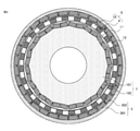
- FIG. It is sectional drawing of the magnetic flux modulation type magnetic gear of Embodiment 1.
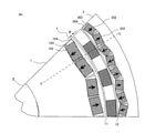
- FIG. It is a partial cross-sectional view of the magnetic flux modulation type magnetic gear of Embodiment 1.
- FIG. It is a partial cross-sectional view of the 1st rotor of Embodiment 1.
- FIG. It is a partial cross-sectional view of the magnetic flux modulation type magnetic gear of Embodiment 2.
- FIG. It is a partial cross-sectional view of the magnetic flux modulation type magnetic gear of Embodiment 3.
- FIG. It is a partial cross-sectional view of the magnetic flux modulation type magnetic gear of Embodiment 4.
- FIG. It is a partial cross-sectional view of the magnetic flux modulation type magnetic gear of Embodiment 5.
- FIG. 1 is a cross-sectional view taken along the rotation axis of the magnetic flux modulation type magnetic gear according to the first embodiment.
- the same reference numerals in the following figures indicate the same or corresponding parts, respectively.
- FIG. 1 shows a schematic configuration of a magnetic flux modulation type magnetic gear which is the subject of the present application.
- the magnetic flux modulation type magnetic gear shown here is a radial type magnetic flux modulation type magnetic gear.
- the first rotor 1, the second rotor 3, and the second rotor 3 having different inner diameters concentrically with respect to the rotation center of the first rotation shaft 2 of the first rotor 1.
- a magnetic material called a pole piece (hereinafter referred to as a pole piece 4) and a stator 5 as an annular member provided with a plurality of pole pieces 4 in an annular shape are arranged, and the stator 5 is arranged inside the stator 5, that is, on the inner peripheral side.
- the first rotor 1 is arranged, and the second rotor 3 is arranged on the outside of the stator 5, that is, on the outer peripheral side.
- the first rotor 1 is attached to the first rotating shaft 2, and the second rotor 3 is attached to the second rotating shaft 6.
- a first bearing 7 is provided between the first rotor 1 and the stator 5
- a second bearing 8 is provided between the stator 5 and the second rotor 3
- a first bearing 8 is provided.
- the rotor 1 and the second rotor 3 are configured so that they can rotate independently of each other.
- FIG. 2 shows the configuration of the magnetic coupling portion 9 shown in FIG. 1, and is a cross-sectional view taken along the line AA in FIG.
- the stator 5 is a fixing portion made of 24 pole pieces 4 made of magnetic materials arranged at equal intervals on an annulus and a non-conductive material that fills a gap between the pole pieces 4 for fixing the pole pieces 4.
- the first rotor 1 arranged on the inner diameter side of the stator 5 is arranged via the first magnetic gap 11 with respect to the circumferential inner diameter surface of the pole piece 4.
- the first rotor 1 is a small pole rotor made by embedding 32 flat plate-shaped first permanent magnets 102 in the first magnetic material 101.
- the second rotor 3 arranged on the outer diameter side of the stator 5 is arranged via the second magnetic gap 12 with respect to the circumferential outer diameter surface of the pole piece 4.
- the second rotor 3 is a multi-pole rotor created by embedding 32 flat plate-shaped second permanent magnets 302 in the second magnetic material 301. That is, one permanent magnet constitutes one magnetic pole.
- FIG. 3 shows the small pole rotor of the magnetic flux modulation type magnetic gear shown in FIG. 2, that is, the two magnetic poles of the first rotor 1, the multipole rotor, that is, the four magnetic poles of the second rotor 3, and the stator 5. It is an enlarged view of.
- the first permanent magnet 102 of the first rotor 1 is formed by two permanent magnets adjacent to each other to form one magnetic pole, and is magnetized in the direction in which the magnetic flux is directed to the first magnetic gap portion 11. Moreover, the magnetism is arranged so as to be reversed for each adjacent magnetic pole.
- the first permanent magnet 102 has a flat plate shape, is arranged symmetrically with respect to a line segment (broken line C in FIG. 3) indicating the center of the magnetic pole as seen from the center of the first rotating shaft 2 at one magnetic pole, and is the first. If the angle formed by the direction of the permanent magnet 102 of 1 and the line segment indicating the magnetic pole center seen from the center of the first rotation axis 2 (broken line C in FIG. 3) is ⁇ , the angle satisfying the relationship of ⁇ ⁇ 90 °. Is predetermined.
- one permanent magnet constitutes one magnetic pole, and is magnetized in the direction in which the magnetic flux directs to the second magnetic gap portion 12, and the magnetization direction is It is arranged so as to reverse each of the adjacent magnetic poles.
- the first permanent magnet 102 passes through the point B closest to the first magnetic gap 11 of the first permanent magnet 102 constituting one magnetic pole of the first rotor 1, and is the first rotor.
- the permanent magnets are arranged in a direction away from the magnetic gap portion with respect to the arc X whose origin is the center of rotation of 1 (corresponding to the center of the first rotation axis 2). That is, the first permanent magnet 102 is embedded in the direction of the first rotation axis 2 from the position of the point B from the outer peripheral surface of the first rotor 1.
- a first cavity 103 for preventing a magnetic flux short circuit is provided at the longitudinal end of the first permanent magnet 102 of the first rotor 1, and the second permanent magnet 3 of the second rotor 3 is provided.
- a second cavity 303 for preventing a magnetic flux short circuit is provided at the end of the magnet 302.
- the first rotor 1 is provided with a first hole 104 for accommodating the first permanent magnet 102, and the first permanent magnet 1 is housed in the first hole 104. It means that the space of the first cavity 103 remains at the end of the magnet 102.
- the second rotor 3 also has a second perforated portion 304, houses the second permanent magnet 302 in the second perforated portion 304, and ends of the second permanent magnet 302. It means that the space of the second cavity portion 303 remains in the portion.
- the configuration of one magnetic pole of the first rotor 1 in FIG. 3 is enlarged and shown in FIG.
- the first hole 104 will include a cavity inside the first rotor 1. That is, a bridge portion 105 having a thickness from the outer peripheral surface of the first rotor 1 to the inner wall surface of the first hole portion 104 is configured.
- the first hole portion 104 is provided inside the arc X having the dimension Lm.
- the dimension Lm is the minimum value for relaxing the stress concentration corresponding to the centrifugal force applied to the first permanent magnet 102. Therefore, there is no problem if the dimension of the bridge portion 105 in the radial direction is larger than the minimum dimension Lm.
- FIG. 4 shows a case where the dimension Lm and the dimension L1 are equal to each other.
- the fact that the bridge portion 105 in the radial direction is formed means that the first permanent magnet 102 of the first rotor 1 is embedded in the direction away from the first magnetic gap portion 11.
- a radial bridge portion also exists in the relationship between the second permanent magnet 302 and the second magnetic gap portion 12 in the second rotor 3. However, since the centrifugal force applied to the second permanent magnet 302 acts outward from the second magnetic gap portion 12, the thickness of the radial bridge portion in the second rotor 3 can be set small. can.
- the magnetic material sandwiched between the space portions (first cavity portion 103 and second cavity portion 303) adjacent to each other in the circumferential direction to prevent the magnetic flux short circuit causes the circumferential direction.
- the bridge part of is configured.
- the dimension W1 of the bridge portion in the circumferential direction of the first rotor 1 is set to be larger than the dimension W2 of the bridge portion in the circumferential direction of the second rotor 3. This makes it possible to strengthen the prevention of scattering of permanent magnets due to centrifugal force.
- the demagnetization resistance can be improved by deepening the embedded position of the first permanent magnet 102, and the first permanent magnet 102 is a magnetic pole seen from the first rotating shaft 2.
- the decrease in torque is reduced by accommodating the magnet inside the first rotor by inclining it at a predetermined angle with respect to the line segment indicating the center. That is, by increasing the amount of the permanent magnets constituting one magnetic pole of the first rotor 1, it contributes to suppressing the decrease in torque.
- the relationship between the orientation of the flat plate magnet and the angle ⁇ formed by the line segment indicating the center of the magnetic pole as seen from the center of the axis of rotation satisfies the relationship of ⁇ ⁇ 90 °. While increasing the amount of magnets used, flat plate-shaped magnets with low manufacturing costs can be used, and manufacturing costs can be expected to be suppressed.
- FIG. 5 is a partial cross-sectional view showing the configuration of the magnetic flux modulation type magnetic gear according to the second embodiment.
- the arrangement of the second permanent magnet 302 of the second rotor 3 of the first embodiment is changed.
- the second permanent magnet 302 is embedded so as to be magnetized in the circumferential direction.
- Other configurations are the same as those in the first embodiment.
- FIG. 6 is a partial cross-sectional view showing the configuration of the magnetic flux modulation type magnetic gear according to the third embodiment.
- the second permanent magnet 302 of the second rotor 3 of the first embodiment is modified.
- the second permanent magnet 302 of the second rotor 3 uses two permanent magnets per magnetic pole, and the two second permanent magnets 302 constituting one magnetic pole are both magnetically second. It is magnetized in the direction of the gap portion 12, and the magnetizing directions of the adjacent magnetic poles are reversed. Other configurations are the same as those in the first embodiment.
- the amount of magnet used in the second permanent magnet 302 of the second rotor 3 can be increased in the same manner as in the first rotor 1. Further, the demagnetization resistance of the second permanent magnet 302 of the second rotor 3 is also improved.
- FIG. 7 is a partial cross-sectional view showing the configuration of the magnetic flux modulation type magnetic gear according to the fourth embodiment.
- the first permanent magnet 102 of the first rotor 1 is composed of one magnet per magnetic pole, and has a bent portion 106 in a direction away from the first magnetic gap portion 11 near the center of the magnetic pole. It is a structure. Due to the configuration of the bent portion 106, the same effect as that of the first embodiment can be obtained while suppressing the number of permanent magnets used.
- the permanent magnet material of the first rotor 1 a bond magnet having a high degree of freedom in shape design can be used. Other configurations are the same as those in the first embodiment. Further, a synergistic effect can be expected by implementing the configuration of the first rotor 1 in combination with the configuration of the second rotor 3 of the second embodiment or the third embodiment.
- FIG. 8 is a partial cross-sectional view showing the configuration of the magnetic flux modulation type magnetic gear according to the fifth embodiment.
- the first permanent magnet 102 of the first rotor 1 is composed of three flat plate-shaped magnets per pole, two of which are at an angle of less than 90 ° with respect to the center of the magnetic pole. It is embedded symmetrically, and the remaining one is embedded perpendicularly and symmetrically to the center of the magnetic pole.
- FIG. 9 is a partial cross-sectional view showing the configuration of the magnetic flux modulation type magnetic gear according to the sixth embodiment.
- the pole piece 4 is configured to be rotated by some external force, and the second rotor 3 is fixed. Since the second rotor 3 does not rotate, it is referred to as the outer magnetic pole structure 31 here. Since the outer magnetic pole structure 31 is fixed in this way, a cooling mechanism can be easily added, and the risk of thermal demagnetization of the magnet can be reduced. Further, while the permanent magnet of the first rotor has 6 poles, the outer magnetic pole structure 31 has 22 poles, and the pole piece 4 has 14 poles. Other configurations are the same as those in the first embodiment.
- the order of the cogging torque caused by the interaction of the magnetomotive force between the first rotor 1 and the outer magnetic pole structure 31 is the number of poles of the first rotor 1 and the outer magnetic pole structure 31. It is represented by the least common multiple of the number of poles.
- the ratio of the number of poles is expressed by a common divisor
- the number of poles of the first rotor 1 and the number of poles of the outer magnetic pole structure 31 do not have a common divisor larger than 2, and therefore the number of poles.
- the ratio of the number of poles of the first rotor 1 to the number of poles of the outer magnetic pole structure 31 is an irreducible fraction that is not an integer.
- the cogging torque can be reduced when the greatest common divisor of the number of poles of the first rotor and the number of poles of the second rotor is 2.
- the fact that the order of the cogging torque is large means that the order of the fluctuation of the magnetic energy is large, that is, the skin depth of the harmonic flux penetrating the iron core material is small due to the skin effect.
- the amount of harmonic flux passing through the magnet via the iron core can be reduced, and the demagnetization resistance can be improved by the synergistic effect of embedding the permanent magnet in the iron core.
- the ratio of the number of poles of the rotor 1 to the number of poles of the outer magnetic pole structure 31 is not an integer, but is expressed as an irreducible fraction, and the same applies when the combination of the number of poles and the number of pole pieces 4 is different from this. The effect is obtained. Further, in the above embodiment, the case where the number of magnets per magnetic pole is 1, 2, and 3 is shown, but the same effect can be obtained even when the number of magnets is 4 or more.
- the annular member formed by the pole piece 4 is used as a stator, and the small pole rotor as the first rotor 1 is arranged on the inner diameter side with respect to the stator.
- the case where the multi-pole rotor as the rotor 3 of 2 is arranged on the outer diameter side is shown, but the same effect can be obtained when the small-pole rotor is arranged on the outer diameter side and the multi-pole rotor is arranged on the inner diameter side. be able to.
- the case where the small pole rotor having the permanent magnet and the multi-pole rotor are free to rotate and the pole piece 4 is fixed is shown, but the same as in the sixth embodiment.
- pole piece 4 By adopting a configuration in which the pole piece 4 is rotated by some external force, it is possible to realize a mechanical planetary gear relationship by setting the rotational speed relationship between the two rotors inside and outside and the annular member of the pole piece. can. Further, a small pole rotor or a multi pole rotor may be fixed.
- one magnetic pole of the second rotor 3 is composed of two permanent magnets arranged in the radial direction, but two or more permanent magnets are used and arranged in the axial direction. Can be combined and configured.
- two or more permanent magnets for example, a first for embedding a magnet so that a standard plate-shaped permanent magnet having a certain size can be combined in the radial and axial directions to form one magnetic pole.
- the pores in addition to the above-mentioned effects, the effect of suppressing the manufacturing cost can be obtained. This effect is particularly remarkable when a magnetic gear having multiple poles or a high reduction ratio is configured, for example, when a magnetic gear is used for the reduction mechanism of a traction motor for an automobile.
- the magnetic structure per pole is symmetric with respect to the center of the magnetic pole
- the magnetic structure may be asymmetrical with respect to the center of the magnetic pole, and the characteristics differ in the rotation direction.
- the same effect can be obtained for those that become.
- the case of the magnetic flux modulation type magnetic gear in the case where the magnetic gap portion is a radial type parallel to the rotation axis is shown, but the magnetic gap portion is an axial type perpendicular to the rotation axis.
- the same effect can be obtained.
Landscapes
- Engineering & Computer Science (AREA)
- Power Engineering (AREA)
- Dynamo-Electric Clutches, Dynamo-Electric Brakes (AREA)
- Permanent Field Magnets Of Synchronous Machinery (AREA)
Priority Applications (4)
| Application Number | Priority Date | Filing Date | Title |
|---|---|---|---|
| CN202080104855.2A CN116134246B (zh) | 2020-08-03 | 2020-12-01 | 磁通调制型磁力齿轮 |
| US18/008,667 US12316189B2 (en) | 2020-08-03 | 2020-12-01 | Magnetic flux modulation type magnetic gear |
| DE112020007478.1T DE112020007478T5 (de) | 2020-08-03 | 2020-12-01 | Magnetgetriebe vom magnetfluss-modulationstyp |
| JP2022541106A JP7412568B2 (ja) | 2020-08-03 | 2020-12-01 | 磁束変調型磁気歯車 |
Applications Claiming Priority (2)
| Application Number | Priority Date | Filing Date | Title |
|---|---|---|---|
| JP2020131387 | 2020-08-03 | ||
| JP2020-131387 | 2020-08-03 |
Publications (1)
| Publication Number | Publication Date |
|---|---|
| WO2022030031A1 true WO2022030031A1 (ja) | 2022-02-10 |
Family
ID=80117205
Family Applications (1)
| Application Number | Title | Priority Date | Filing Date |
|---|---|---|---|
| PCT/JP2020/044593 Ceased WO2022030031A1 (ja) | 2020-08-03 | 2020-12-01 | 磁束変調型磁気歯車 |
Country Status (5)
| Country | Link |
|---|---|
| US (1) | US12316189B2 (https=) |
| JP (1) | JP7412568B2 (https=) |
| CN (1) | CN116134246B (https=) |
| DE (1) | DE112020007478T5 (https=) |
| WO (1) | WO2022030031A1 (https=) |
Cited By (1)
| Publication number | Priority date | Publication date | Assignee | Title |
|---|---|---|---|---|
| WO2025164799A1 (ja) * | 2024-01-31 | 2025-08-07 | ミネベアミツミ株式会社 | 動力伝達装置 |
Citations (3)
| Publication number | Priority date | Publication date | Assignee | Title |
|---|---|---|---|---|
| JP2012157205A (ja) * | 2011-01-28 | 2012-08-16 | Hitachi Ltd | 磁気歯車 |
| WO2012114368A1 (ja) * | 2011-02-21 | 2012-08-30 | 株式会社 日立製作所 | 磁気歯車機構 |
| JP2013011298A (ja) * | 2011-06-29 | 2013-01-17 | Hitachi Ltd | 磁気式歯車機構 |
Family Cites Families (8)
| Publication number | Priority date | Publication date | Assignee | Title |
|---|---|---|---|---|
| CN101897108B (zh) * | 2007-12-26 | 2013-04-10 | 本田技研工业株式会社 | 电动机以及旋转电机用转子 |
| GB0800463D0 (en) * | 2008-01-11 | 2008-02-20 | Magnomatics Ltd | Magnetic drive systems |
| JP2015061422A (ja) * | 2013-09-19 | 2015-03-30 | 株式会社デンソー | 動力伝達機構 |
| US9479017B2 (en) * | 2014-07-22 | 2016-10-25 | GM Global Technology Operations LLC | Deep V-magnet cavity structure rotor |
| US20170126087A1 (en) * | 2015-10-30 | 2017-05-04 | Rod F. Soderberg | Device including material originating from magnetic particles providing structural and magnetic capabilities |
| CN105391265B (zh) * | 2015-12-21 | 2018-02-23 | 东南大学 | 一种无刷谐波励磁的混合励磁容错电机系统 |
| CN108471211A (zh) * | 2018-04-13 | 2018-08-31 | 哈尔滨理工大学 | 一种提高永磁同步电机弱磁扩速性能的转子结构 |
| JP7361344B2 (ja) * | 2019-02-26 | 2023-10-16 | パナソニックIpマネジメント株式会社 | 磁気ギアードモータ |
-
2020
- 2020-12-01 US US18/008,667 patent/US12316189B2/en active Active
- 2020-12-01 DE DE112020007478.1T patent/DE112020007478T5/de active Pending
- 2020-12-01 JP JP2022541106A patent/JP7412568B2/ja active Active
- 2020-12-01 WO PCT/JP2020/044593 patent/WO2022030031A1/ja not_active Ceased
- 2020-12-01 CN CN202080104855.2A patent/CN116134246B/zh active Active
Patent Citations (3)
| Publication number | Priority date | Publication date | Assignee | Title |
|---|---|---|---|---|
| JP2012157205A (ja) * | 2011-01-28 | 2012-08-16 | Hitachi Ltd | 磁気歯車 |
| WO2012114368A1 (ja) * | 2011-02-21 | 2012-08-30 | 株式会社 日立製作所 | 磁気歯車機構 |
| JP2013011298A (ja) * | 2011-06-29 | 2013-01-17 | Hitachi Ltd | 磁気式歯車機構 |
Cited By (1)
| Publication number | Priority date | Publication date | Assignee | Title |
|---|---|---|---|---|
| WO2025164799A1 (ja) * | 2024-01-31 | 2025-08-07 | ミネベアミツミ株式会社 | 動力伝達装置 |
Also Published As
| Publication number | Publication date |
|---|---|
| DE112020007478T5 (de) | 2023-05-17 |
| CN116134246B (zh) | 2025-07-01 |
| JP7412568B2 (ja) | 2024-01-12 |
| JPWO2022030031A1 (https=) | 2022-02-10 |
| US12316189B2 (en) | 2025-05-27 |
| US20230246536A1 (en) | 2023-08-03 |
| CN116134246A (zh) | 2023-05-16 |
Similar Documents
| Publication | Publication Date | Title |
|---|---|---|
| JP4394115B2 (ja) | アキシャルギャップ型モータ | |
| JP5108236B2 (ja) | モータ用ロータ | |
| US9071118B2 (en) | Axial motor | |
| JP4692090B2 (ja) | アキシャルエアギャップ型電動機 | |
| CN101548452B (zh) | 轴向间隙型电动机 | |
| CN101779366B (zh) | 轴向间隙型电动机 | |
| JP2012100424A (ja) | 回転電機のロータ | |
| CN102420473A (zh) | 转子 | |
| WO2012105656A1 (ja) | 車両用永久磁石埋込型回転電機 | |
| JPWO2011125308A1 (ja) | 永久磁石形回転電機の回転子 | |
| JP2013017285A (ja) | 磁気ギア装置 | |
| WO2021149130A1 (ja) | 固定子およびこれを用いた回転電機 | |
| JP5194984B2 (ja) | 永久磁石型ロータ | |
| WO2022030031A1 (ja) | 磁束変調型磁気歯車 | |
| JP6976492B1 (ja) | 磁束変調型磁気ギア | |
| JP2006304539A (ja) | アキシャルギャップ型回転電機のロータ構造 | |
| JP5017045B2 (ja) | アキシャルギャップ型モータ | |
| CN114946107A (zh) | 定子以及使用该定子的旋转电机 | |
| JP2008187802A (ja) | 回転電機の回転子及び回転電機 | |
| JP2006304532A (ja) | アキシャルギャップ型回転電機のロータ構造 | |
| JP2009118550A (ja) | アキシャルギャップ型モータ | |
| JP2017053480A (ja) | 磁気歯車装置 | |
| JP5124998B2 (ja) | 回転電機 | |
| WO2012086613A1 (ja) | 回転電機 | |
| JP4896690B2 (ja) | アキシャルギャップ型モータ |
Legal Events
| Date | Code | Title | Description |
|---|---|---|---|
| 121 | Ep: the epo has been informed by wipo that ep was designated in this application |
Ref document number: 20948310 Country of ref document: EP Kind code of ref document: A1 |
|
| ENP | Entry into the national phase |
Ref document number: 2022541106 Country of ref document: JP Kind code of ref document: A |
|
| 122 | Ep: pct application non-entry in european phase |
Ref document number: 20948310 Country of ref document: EP Kind code of ref document: A1 |
|
| WWG | Wipo information: grant in national office |
Ref document number: 18008667 Country of ref document: US |
|
| WWG | Wipo information: grant in national office |
Ref document number: 202080104855.2 Country of ref document: CN |