WO2022029892A1 - 蓄電池内部状態推定装置及び蓄電池内部状態推定方法 - Google Patents
蓄電池内部状態推定装置及び蓄電池内部状態推定方法 Download PDFInfo
- Publication number
- WO2022029892A1 WO2022029892A1 PCT/JP2020/029841 JP2020029841W WO2022029892A1 WO 2022029892 A1 WO2022029892 A1 WO 2022029892A1 JP 2020029841 W JP2020029841 W JP 2020029841W WO 2022029892 A1 WO2022029892 A1 WO 2022029892A1
- Authority
- WO
- WIPO (PCT)
- Prior art keywords
- storage battery
- estimation
- function
- series data
- internal state
- Prior art date
- Legal status (The legal status is an assumption and is not a legal conclusion. Google has not performed a legal analysis and makes no representation as to the accuracy of the status listed.)
- Ceased
Links
Images






Classifications
-
- G—PHYSICS
- G01—MEASURING; TESTING
- G01R—MEASURING ELECTRIC VARIABLES; MEASURING MAGNETIC VARIABLES
- G01R31/00—Arrangements for testing electric properties; Arrangements for locating electric faults; Arrangements for electrical testing characterised by what is being tested not provided for elsewhere
- G01R31/36—Arrangements for testing, measuring or monitoring the electrical condition of accumulators or electric batteries, e.g. capacity or state of charge [SoC]
- G01R31/367—Software therefor, e.g. for battery testing using modelling or look-up tables
-
- H—ELECTRICITY
- H02—GENERATION; CONVERSION OR DISTRIBUTION OF ELECTRIC POWER
- H02J—ELECTRIC POWER NETWORKS; CIRCUIT ARRANGEMENTS OR SYSTEMS FOR SUPPLYING OR DISTRIBUTING ELECTRIC POWER; SYSTEMS FOR STORING ELECTRIC ENERGY
- H02J7/00—Circuit arrangements for charging or discharging batteries or for supplying loads from batteries
- H02J7/80—Circuit arrangements for charging or discharging batteries or for supplying loads from batteries including monitoring or indicating arrangements
- H02J7/84—Control of state of health [SOH]
-
- G—PHYSICS
- G01—MEASURING; TESTING
- G01R—MEASURING ELECTRIC VARIABLES; MEASURING MAGNETIC VARIABLES
- G01R31/00—Arrangements for testing electric properties; Arrangements for locating electric faults; Arrangements for electrical testing characterised by what is being tested not provided for elsewhere
- G01R31/36—Arrangements for testing, measuring or monitoring the electrical condition of accumulators or electric batteries, e.g. capacity or state of charge [SoC]
- G01R31/382—Arrangements for monitoring battery or accumulator variables, e.g. SoC
- G01R31/3842—Arrangements for monitoring battery or accumulator variables, e.g. SoC combining voltage and current measurements
-
- G—PHYSICS
- G01—MEASURING; TESTING
- G01R—MEASURING ELECTRIC VARIABLES; MEASURING MAGNETIC VARIABLES
- G01R31/00—Arrangements for testing electric properties; Arrangements for locating electric faults; Arrangements for electrical testing characterised by what is being tested not provided for elsewhere
- G01R31/36—Arrangements for testing, measuring or monitoring the electrical condition of accumulators or electric batteries, e.g. capacity or state of charge [SoC]
- G01R31/392—Determining battery ageing or deterioration, e.g. state of health
-
- H—ELECTRICITY
- H01—ELECTRIC ELEMENTS
- H01M—PROCESSES OR MEANS, e.g. BATTERIES, FOR THE DIRECT CONVERSION OF CHEMICAL ENERGY INTO ELECTRICAL ENERGY
- H01M10/00—Secondary cells; Manufacture thereof
- H01M10/42—Methods or arrangements for servicing or maintenance of secondary cells or secondary half-cells
-
- H—ELECTRICITY
- H01—ELECTRIC ELEMENTS
- H01M—PROCESSES OR MEANS, e.g. BATTERIES, FOR THE DIRECT CONVERSION OF CHEMICAL ENERGY INTO ELECTRICAL ENERGY
- H01M10/00—Secondary cells; Manufacture thereof
- H01M10/42—Methods or arrangements for servicing or maintenance of secondary cells or secondary half-cells
- H01M10/48—Accumulators combined with arrangements for measuring, testing or indicating the condition of cells, e.g. the level or density of the electrolyte
-
- Y—GENERAL TAGGING OF NEW TECHNOLOGICAL DEVELOPMENTS; GENERAL TAGGING OF CROSS-SECTIONAL TECHNOLOGIES SPANNING OVER SEVERAL SECTIONS OF THE IPC; TECHNICAL SUBJECTS COVERED BY FORMER USPC CROSS-REFERENCE ART COLLECTIONS [XRACs] AND DIGESTS
- Y02—TECHNOLOGIES OR APPLICATIONS FOR MITIGATION OR ADAPTATION AGAINST CLIMATE CHANGE
- Y02E—REDUCTION OF GREENHOUSE GAS [GHG] EMISSIONS, RELATED TO ENERGY GENERATION, TRANSMISSION OR DISTRIBUTION
- Y02E60/00—Enabling technologies; Technologies with a potential or indirect contribution to GHG emissions mitigation
- Y02E60/10—Energy storage using batteries
Definitions
- the present disclosure relates to a storage battery internal state estimation device for estimating the internal state of the storage battery and a storage battery internal state estimation method.
- Electric vehicles such as EV (electric vehicle: Electric Vehicle), HEV (hybrid electric vehicle: Hybrid Electric Vehicle), PHV (plug-in hybrid vehicle: Plug-in Hybrid Vehicle) have been put into practical use.
- EV electric vehicle: Electric Vehicle
- HEV hybrid electric vehicle: Hybrid Electric Vehicle
- PHV plug-in Hybrid Vehicle
- Storage batteries such as lithium-ion batteries are used in these devices. It is known that the storage battery deteriorates with use and its performance deteriorates. In order to understand the performance and replacement time of these storage batteries and to predict the life of the storage batteries, it is necessary to diagnose the deterioration of the storage batteries.
- Patent Document 1 discloses a method using a differential voltage curve.
- the procedure for implementing this method is as follows. First, the differential voltage curve obtained from the electrical characteristics of the positive electrode material and the negative electrode material of the storage battery is acquired in advance. Next, the fitting function that fits this differential voltage curve and the parameters of this fitting function are calculated. Finally, deterioration diagnosis is performed based on the fluctuation of the parameters of the fitting function calculated from the peak position, peak height, peak width, etc. in the differential voltage curve obtained from the measured values of the storage battery in use.
- the positive electrode voltage curve and the negative electrode voltage curve obtained from the electrical characteristics of the positive electrode material and the negative electrode material of the storage battery obtained in advance are often of the electrode charge rate-voltage curve with the horizontal axis as the electrode charge rate.
- different deterioration modes are quantitatively estimated by reducing or shifting the electrode capacity-voltage curve acquired in advance with the horizontal axis of the positive electrode and the negative electrode as the electrode charge amount, respectively.
- the capacity-voltage curve of the deteriorated storage battery cell is modeled.
- a phenomenon is observed in which the shape of the electrode capacitance-voltage curve changes and the local fluctuation of the voltage becomes gentle.
- the shape of the electrode capacitance-voltage curve often has a gentle peak when viewed from the differential voltage curve.
- This phenomenon occurs because as the storage battery deteriorates, the degree of deterioration among a large number of particles constituting the electrode varies, and the conductive path between each particle and the current collector is likely to be interrupted. This is thought to be due to variations in the charge rate for each particle during charging and discharging. Therefore, instead of using the characteristic information of the storage battery acquired in advance as it is, an accurate deterioration diagnosis technique by modeling the storage battery voltage curve that can reflect the shape change of the voltage curve or the differential voltage curve according to the deterioration is required. Has been done.
- the present disclosure has been made in view of the above, and an object of the present invention is to obtain a storage battery internal state estimation device capable of accurate deterioration diagnosis even when there is no characteristic information of the storage battery to be diagnosed.
- the storage battery internal state estimation device includes a data generation unit and an estimation unit.
- the data generation unit generates estimation time-series data from the time-series data of the current value and the voltage value acquired from the storage battery.
- the estimation unit estimates the model function of the storage battery based on the estimation time series data.
- the storage battery internal state estimation device According to the storage battery internal state estimation device according to the present disclosure, there is an effect that accurate deterioration diagnosis can be performed even if there is no characteristic information of the storage battery to be diagnosed.
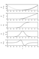
- the figure which plotted the curve from the second-order derivative to the second-order integral when the value of the scale ⁇ in the logistic function used in the proposed method of the first embodiment is changed.
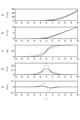
- the figure which plotted the curve of the even-order integral function from the second-order integral to the tenth-order integral when the value of scale ⁇ in the logistic function used in the proposed method of Embodiment 1 is changed.
- a characteristic diagram showing an example of the potential curve of the negative electrode and the differential potential curve of the negative electrode in the same lithium ion battery as shown in FIG. A diagram showing an example of separation and estimation by higher order differentiation performed using the proposed method of Embodiment 1.
- FIG. 1 A flowchart showing an example of a processing procedure by the storage battery internal state estimation method according to the first embodiment.
- FIG. 1 is a diagram showing a configuration example of a storage battery deterioration diagnosis system 100 including a storage battery internal state estimation device 1 according to the first embodiment.
- the storage battery deterioration diagnosis system 100 includes a storage battery internal state estimation device 1, a storage battery 2, a current detection device 3, and a voltage detection device 4.
- the storage battery internal state estimation device 1 according to the first embodiment is a device that estimates the internal state of the storage battery 2.
- the estimation of the internal state includes the estimation of the deterioration state of the storage battery 2, and the estimation of the deterioration parameters that are indicators of the degree and progress of the deterioration of the storage battery 2, the degree of capacity decrease of the storage battery 2, and the degree of deterioration of the storage battery 2. It is a concept that also includes.
- a lithium-ion battery to be diagnosed is a lithium-ion battery that uses an NMC-based material for the positive electrode and graphite for the negative electrode.
- the storage battery 2 to be diagnosed may include a general storage battery having a positive electrode and a negative electrode and capable of charging and discharging, in addition to a lithium ion battery composed of another material system. .. Further, the storage battery 2 to be diagnosed may be a lead storage battery, a nickel hydrogen storage battery, an all-solid-state storage battery, or the like, in addition to the lithium ion battery.
- the storage battery 2 to be diagnosed may be a storage battery module in which a plurality of cells are connected in series or a storage battery module in which a plurality of cells are connected in parallel, in addition to the storage battery of a single cell.
- the storage battery to be diagnosed may be a storage battery module configured by combining a series connection and a parallel connection of a plurality of cells. Further, a plurality of storage battery modules in which a single storage battery module is connected in parallel may be used.
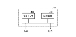
- FIG. 2 is a block diagram showing an example of the hardware configuration of the storage battery internal state estimation device 1 according to the first embodiment.
- the storage battery internal state estimation device 1 includes a data generation unit 5 and an estimation unit 60.
- the estimation unit 60 includes a separation estimation unit 6, an integrated estimation unit 7, and a deterioration diagnosis unit 8.
- FIG. 2 shows an example of the hardware configuration of the storage battery internal state estimation device 1.
- the storage battery internal state estimation device 1 includes a controller 40.
- the controller 40 includes a processor 400 and a storage device 401.
- the functions of each unit constituting the storage battery internal state estimation device 1, that is, the functions of the data generation unit 5, the separation estimation unit 6, the integrated estimation unit 7, and the deterioration diagnosis unit 8 are realized by software, firmware, or a combination thereof.
- the software and firmware are described as a program and are stored in the storage device 401.
- the processor 400 realizes the functions of each part of the storage battery internal state estimation device 1 by reading the program stored in the storage device 401 and executing the program.
- the current detection device 3 detects the current of the storage battery 2 and outputs the time series data of the current to the data generation unit 5.
- the voltage detection device 4 detects the voltage of the storage battery 2 and outputs the time series data of the voltage to the data generation unit 5.
- the sampling period of the time series data is ts (seconds).
- the storage battery 2 to be diagnosed is a single storage battery cell
- the single storage battery cell is a single cell lithium ion battery. ..
- the current detection device 3 and the voltage detection device 4 may detect the current and the voltage of each unit storage battery, respectively.
- each of the following parts operates in the same manner as the number of target storage batteries 2.
- the unit storage battery may be a storage battery cell, or may be a storage battery module by a combination of series connection or parallel connection of storage battery cells.
- the data generation unit 5 generates data point sequences of each of the voltage value V , the standardized capacity, the ND higher-order differential voltage and the NI higher-order integrated voltage as time-series data for estimation.
- the generated time-series data for estimation is input to the estimation unit 60.
- the data generation unit 5 may save a part or all of the generated data point sequence, and outputs a part or all of the data point sequence saved in the past together with the currently acquired or generated data point sequence. May be good.
- the data point sequence generated by the data generation unit 5 can be expressed as the following equation (1).
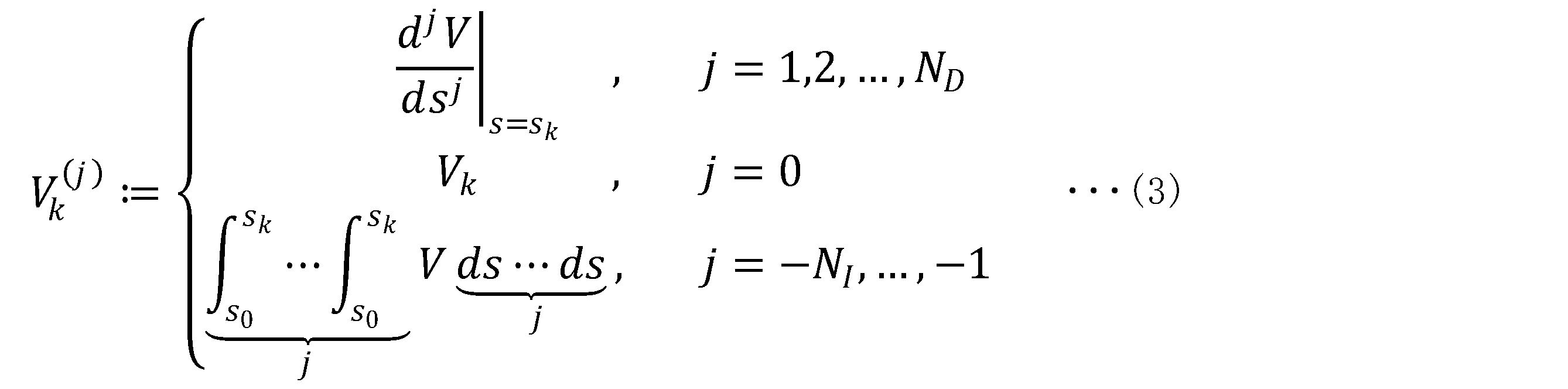
- V k (j) is the differential voltage, voltage, or integral voltage of the discrete time k. Further, this V k (j) is defined as the following equation (3).
- the normalized capacity sk can be calculated by using the following equations (4) and (5) from the capacity q k representing the storage capacity of the electric energy (coulomb).
- q type in the denominator of the above equation (5) is a standardized full charge capacity.
- the standardized full charge capacity q type typically, the rated full charge capacity of the storage battery 2 to be diagnosed or the full charge capacity when new can be used.
- X k means the value of X at the discrete time k.
- the standardized capacity sk is the SOC (charge state: State Of Charge) at the discrete time k , which is a sampling parameter when the standardized full charge capacity q type is used as a reference.
- the capacity q k may be used instead of the standardized capacity sk.
- the initial electric energy q 0 of the storage battery 2 is calculated by the following equations (6) and (7) using the relationship between the SOC of the storage battery 2 and the OCV (open circuit voltage: Open Circuit Voltage). Can be done.
- q max is the full charge capacity of the storage battery 2.
- the full charge capacity q max an estimated value of the full charge capacity of the storage battery 2 or a standardized full charge capacity q type can be used.
- the function f for example, a plurality of data points representing the relationship between SOC and OCV, which are acquired in advance by repeating energization and suspension of the storage battery 2 and the storage battery of the same product, are set on the horizontal axis by OCV. The one obtained by interpolating with the vertical axis as SOC can be used.
- the initial electric energy q 0 may be calculated by the following equation (8) from the SOCe which is the estimated value of the SOC of the storage battery 2 estimated in the system equipped with the storage battery 2.
- the acquired current value I and voltage value V may be noise-reduced by a low-pass filter, Fourier analysis, wavelet analysis, or the like.
- a low-pass filter various filtering processes such as a moving average filter, a Kolmogorov-Zurbenko filter, a Savitzky-Goray filter, an active filter, and a passive filter are known.
- V k (j) ⁇ NI , ..., -1
- the constant of integration may be all zero in the simplest case.
- the data point sequence generated in this way includes the data point sequence generated in the past, the internal storage device 401 of the storage battery internal state estimation device 1, or the external data server and cloud of the storage battery internal state estimation device 1. It may be saved in such as.
- the estimation unit 60 estimates the parameters of the model function of the storage battery 2 based on the estimation time series data which is a data point sequence acquired and generated by the data generation unit 5.
- the parameters of the model function may include deterioration parameters that are indicators of the degree of deterioration of the storage battery 2.
- the estimation unit 60 is typically configured to include a separation estimation unit 6, an integrated estimation unit 7, and a deterioration diagnosis unit 8, as shown in FIG. 1, but the configuration of the estimation unit 60 is a separation estimation unit. It is not essential to include all of the unit 6, the integrated estimation unit 7, and the deterioration diagnosis unit 8.
- the separation estimation unit 6 estimates the parameters of the high-frequency function and the low-frequency function based on the data point sequence acquired and generated by the data generation unit 5.
- the high frequency function is a function in which relatively higher frequency components dominate.
- the low frequency function is a function in which relatively lower frequency components dominate.
- f (x) is a higher-order differential function of f (x) or f (x) or a higher-order integral function of f (x) depending on the value of j. It is assumed that it is defined as the following equation (9).
- the function that is an element constituting the high frequency function is referred to as a "high frequency element function”
- the function that is an element constituting the low frequency function is referred to as a "low frequency element function”.
- the high frequency element function and the low frequency element function are collectively called "element function”.
- the element function will be specifically described by taking a logistic function as an example.
- the logistic function is a kind of sigmoid function and can be expressed by the following equation (10).
- k is a parameter expressing height
- ⁇ is a position
- ⁇ is a parameter expressing scale.
- the scale means the looseness of the function.
- the sigmoid function and its higher-order sigmoid function can be expressed based on the distribution functions of various probability distributions such as Gaussian distribution, Cauchy distribution, hyperbolic second distribution, Student's t distribution, and Student's z distribution.
- FIG. 3 is a diagram plotting curves from the second derivative to the second integral of the logistic function used in the proposed method of the first embodiment.
- scale ⁇ is a parameter that expresses the gentleness of the curve. Therefore, if the value of the scale ⁇ is reduced, each curve becomes steeper, and if the scale ⁇ is increased, each curve becomes gentler. In other words, if the scale ⁇ is made relatively small, the high frequency component becomes the dominant function, that is, the high frequency element function. Further, if the scale ⁇ is relatively large, the low frequency component becomes the dominant function, that is, the low frequency element function.
- FIG. 4 is a diagram plotting a curve from the second derivative to the second integral when the value of the scale ⁇ in the logistic function used in the proposed method of the first embodiment is changed.
- the curve becomes gentle as the scale ⁇ is increased. That is, when the scale ⁇ is increased, it becomes a global function at a lower frequency.
- the scale ⁇ is reduced, the curve becomes steep. That is, when the scale ⁇ is reduced, the function becomes localized at higher frequencies.
- FIG. 5 is a diagram plotting the curve of the even-order integral function from the second-order integral to the tenth-order integral when the value of the scale ⁇ in the logistic function used in the proposed method of the first embodiment is changed.
- FIG. 5 (c) shows the sixth-order integral function of the logistic function.
- the function with the largest scale ⁇ and ⁇ 2 becomes dominant as the integral order increases.
- the height k is a parameter that determines the height of the sigmoid function
- the position ⁇ is a parameter that determines the peak position of the peak function.
- the peak function may be a peak function with left-right asymmetric skewness.
- the density function of the strain normal distribution is known.
- the density function includes an error function
- the distribution function includes an error function and Owen's T function.
- the storage battery internal state estimation device 1 uses a peak function as a model of the differential voltage curve of the storage battery 2.
- the peak function is used as a model of the differential voltage curve, it is desirable that the peak function and the sigmoid function by integrating the peak function can be expressed by elementary functions so that the peak function can also be used as a model of the voltage curve.
- the storage battery internal state estimation device 1 according to the present disclosure proposes a strain sigmoid function represented by the following equation (13).
- the strain peak function by differentiation of the strain sigmoid function can be expressed by the following equation (14).
- strain sigmoid functions and strain peak functions can adjust the degree of strain by adjusting the strain parameter ⁇ .
- f is a known sigmoid function
- f (-1) is a known peak function based on the derivative. Therefore, it is possible to convert various sigmoid functions and peak functions into strain sigmoid functions and strain peak functions by the above equation (14).
- the peak position of the strain peak function deviates from the peak position ⁇ of the known peak function due to the strain. Therefore, the peak position of the distortion peak function is derived. Assuming that the peak position of the strain peak function is x m , the derivative due to x becomes zero at the peak position x m , so the solution can be obtained by solving the following equation (15).
- the peak position x m represented by the following equation (16) can be obtained.
- the formula of the peak position represented by the elementary function can be obtained.
- the peak position x m expressed by the following equation (18) can be obtained.
- FIG. 6 plots a curve for each ⁇ when the value of the strain parameter ⁇ is changed little by little with respect to the strain peak function generated by using the density functions of six types of distributions different by the proposed method of the first embodiment. It is a figure. Specifically, FIG. 6 (a) is an example of a Gaussian distribution, FIG. 6 (b) is an example of a hyperbolic secant distribution, and FIG. 6 (c) is an example of a logistic distribution. Further, FIG. 6 (d) is an example of Student's t distribution, FIG. 6 (e) is an example of Cauchy distribution, and FIG. 6 (f) is an example of Student's t distribution.
- the strain peak function can be constructed from various known sigmoid functions and peak functions, and is highly versatile.
- Distortion can be expressed only by adding one strain parameter ⁇ , which is useful in parameter estimation described later.
- the known sigmoid function to be used can be expressed by an elementary function
- the strain sigmoid function and the strain peak function can also be expressed by an elementary function, so that it is practically easy to handle, especially the voltage curve and the differential voltage curve of the storage battery. Is useful for modeling.
- Iv Since the analytical solution of the peak position of the strain function can be obtained by the elementary function in many cases, it is practically useful, and especially useful for determining the initial value in the parameter estimation described later.
- Up is the positive electrode potential
- Un is the negative electrode potential
- I is the current flowing through the storage battery 2
- R is the resistance of the storage battery 2.
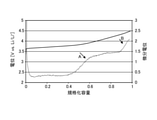
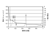
- FIG. 7 is a characteristic diagram showing an example of a positive electrode potential curve and a positive electrode differential potential curve in a general lithium ion battery provided with an NMC-based positive electrode and a graphite negative electrode.
- the horizontal axis is the normalized capacitance of the positive electrode
- the left vertical axis is the potential
- the right vertical axis is the differential potential.
- the solid line represents the potential curve
- the broken line represents the differential potential curve.
- the positive electrode potential curves of many materials such as NMC have a shape in which the potential changes slowly.
- the positive electrode potential function f p ( sp ) can be expressed by, for example, the following equation (20).
- the positive differential potential function f p (1) ( sp ) has a constant term, n p peak functions, and mp sigmoid functions as element functions. It is expressed in Japanese. Therefore, the positive potential function f p ( sp ) shown in the above equation (20), which is related to the integral of the equation (21), has a constant term, a linear term, n p sigmoid functions, and mp. The soft plus function of is used as an element function and is expressed by the sum of them.
- the sigmoid function and the peak function can be well expressed.
- the expressions (20) and (21) above are examples, and other element functions may be used instead of these element functions. Further, as an element function, it is not always necessary to use a function including parameters expressing the height k, the position ⁇ , and the scale ⁇ .
- the differential voltage curve in FIG. 7 can be expressed by a constant term and two sigmoid functions corresponding to the points of arrows A and B, respectively.
- FIG. 8 is a characteristic diagram showing an example of the potential curve of the negative electrode and the differential potential curve of the negative electrode in the same lithium ion battery as shown in FIG. 7.
- the horizontal axis is the normalized capacitance of the negative electrode
- the left vertical axis is the potential
- the right vertical axis is the differential potential in which positive and negative are reversed.
- the solid line represents the potential curve
- the broken line represents the differential potential curve.
- the standardized capacity 1 of the storage battery cell is normally regulated by the positive electrode potential, the vicinity of the standardized capacity 1 of the negative electrode is not used in this characteristic diagram.
- the potential curve of the negative electrode which is graphite
- the potential curve of the positive electrode which is NMC. Has been done. This change corresponds to the peak-shaped curve at the position indicated by the arrow in the differential potential curve.
- the negative electrode potential function f n (s n ) can be expressed by, for example, the following equation (22).
- the negative electrode differential potential function f n (1) (s n ) is expressed by the sum of mn peak functions as element functions. Therefore, the negative electrode potential function f n (s n ) shown in the above equation (22), which is related to the integral of the equation (23), is the sum of the constant term and the mn sigmoid functions as element functions. It is expressed by.
- the element function used here is an example, and other element functions may be used.
- the rising edge of the differential voltage at the left end may be modeled by a peak function, or another function may be used as an element function.
- a sigmoid function may be used.
- an exponential function as shown in the following equation (24) may be used.
- the voltage function of the storage battery cell can be expressed as the following equation (25) according to the above equation (19) and by using the above equations (20) and (22).
- each function is the standardized capacity s of the storage battery cell.
- f e and i are the i-th element functions
- ⁇ i is a vector of parameters included in the i-th element functions f e and i .
- f e, i (s) b p s
- ⁇ i b p
- f e, i (s) f (s n ; k ni , ⁇ ni , ⁇ ni )
- ⁇ i [k ni , ⁇ ni , ⁇ ni ] T.
- model functions of the storage battery cell voltage and the storage battery cell differential voltage can be expressed by the sum of the element functions including at least one of the above-mentioned soft plus function, sigmoid function and peak function. be.
- the separation estimation unit 6 estimates the parameters of the high-frequency function and the low-frequency function based on the data point sequence acquired and generated by the data generation unit 5. Specifically, it is as follows.
- the positive electrode voltage curve and the positive electrode differential voltage curve are expressed by the sum of the element functions as shown in the above equations (20) and (21). Therefore, it is not a good idea to estimate the parameters of all functions at once. Therefore, in the first embodiment, by amplifying at least one specific element function and attenuating the other element function, the other element function is replaced with 0 or an approximate function, and the approximate function and the specific element function are replaced. Estimate the parameters.
- This method has the property that higher-order element functions are extracted because lower-frequency element functions are more attenuated when higher-order differentiation is performed, and higher-frequency element functions are obtained when higher-order integration is performed. Since it is more attenuated, it takes advantage of the property that lower element functions are extracted.
- the parameters of the corresponding element function are estimated so that the error with the extracted data becomes small.
- the parameters of the element functions corresponding to the attenuated components other than the extracted region may be estimated at the same time by using the approximation function. For example, it may be approximated by a constant, or it may be approximated by an nth-order function as described with reference to FIG. That is, there is no limitation on the form of the approximate function.
- the ultimate purpose is to accurately model the voltage curve of the storage battery cell while separating the positive electrode potential curve and the negative electrode potential curve by the voltage function. Therefore, the evaluation function is used to minimize the evaluation function.
- the SN ratio can be improved by including the difference between the voltage function and the higher-order calculus of each voltage data in the evaluation function.
- the initial time and the end time of the data to be used may be different values for different j.
- the sum of squared errors is used here for the sake of simplicity, it is not limited to this.
- the evaluation function can be described in various ways.
- ⁇ (q) represents the index of the element function extracted by the qth-order calculus.
- g q is an approximate function of the attenuated element function when the q-th order calculus is performed
- ⁇ q is a vector in which the parameters of the approximate function are arranged.
- the approximation function is not essential and may be zero.
- q l represents the rank of the calculus used in the first evaluation function.
- h l is a function based on the estimation results up to the l-1st time, and can be expressed by the following equation (32), for example.
- ⁇ * ⁇ (qi) represents an estimated value of ⁇ ⁇ (qi) calculated so as to minimize the evaluation function Ji .
- the function hl makes it possible to improve the accuracy and stabilize the current estimation calculation by the amount that the function estimated in the past can be used. Further, typically, the operation of creating and minimizing the evaluation function in order from the differential data or the integral data of the higher rank is repeated. For higher order differentials, higher order functions are often more dominant on lower rank differential data. Therefore, it is a process of extracting and estimating a higher frequency function with a higher derivative. This makes it possible to remove the influence by subtracting the higher-frequency high-frequency function in the estimation of the lower-frequency high-frequency function in the lower-order differential data.
- a known nonlinear optimization method can be used as a parameter estimation method by minimizing the evaluation functions of the above equations (29) to (31).
- a known nonlinear optimization method can be used as an optimization method.
- a Gauss-Newton method, a Levenberg-Marquardt method, or the like can be used as an optimization method.
- there may be some information regarding the parameter to be estimated for example, information such as a certain parameter being non-negative.
- the optimization method may be formulated as a non-linear optimization problem with constraints by including these pieces of information as constraints.
- a penalty function method a sequential quadratic planning method, a GRG method (Generalized Reduced Gradient method), or the like can be used.
- the optimization method without constraints and with constraints mentioned here is an example, and an optimization method such as metaheuristics may be used as another optimization method. Further, the optimization method may be used properly according to the scale of the problem such as the number of parameters and the scale of computational resources such as the processing speed and the amount of memory.
- the evaluation function is composed of the sum of squared errors, but the method of constructing the evaluation function is not limited to this.
- the sum of squared errors it may be composed of the sum of nth power errors due to n where n ⁇ 2.
- it may be composed of a weighted sum including a regularization term and the like.
- the integrated estimation unit 7 estimates the parameters again based on the parameters estimated by the separation estimation unit 6 so as to minimize the above equation (23). Specifically, at least one of the parameters separately obtained by the separation estimation unit 6 and the parameters not obtained by the separation estimation unit 6 is included, and the parameters already estimated are used as the initial values of the estimation here. Then, all parameters are estimated again.
- the separation estimation unit 6 repeats the estimation of only some element functions.
- the parameters are estimated by setting other element functions attenuated by higher-order calculus to zero or replacing them with approximate functions. Therefore, there is a possibility that the estimation parameters include errors due to the influence of such approximation processing. Therefore, the integrated estimation unit 7 collects the estimated parameters, integrates all the parameters and all the element functions, and performs a process of estimating the parameters of the storage battery voltage function again.
- the processing by the integrated estimation unit 7 can obtain an estimation result with a small error due to the estimation approximation.
- the voltage function of the storage battery 2 can be obtained with high accuracy. Further, even when there is a difference in shape between the positive electrode potential curve and the negative electrode potential curve, it is possible to estimate each function separately while separating them by using the higher-order calculus.
- FIG. 9 is a diagram showing an example of separation and estimation by higher order differentiation performed by using the proposed method of the first embodiment.
- FIG. 9A shows partial data of the first-order differential voltage of the storage battery voltage and the estimation result for the partial data.
- FIG. 9B shows partial data of the second-order differential voltage of the storage battery voltage and the estimation result for the partial data.
- the broken line shows the function of the positive electrode
- the alternate long and short dash line shows the function of the negative electrode
- the solid line shows the estimation result of the function of the storage battery cell.
- the partial data is represented by white circles, it is almost a thick line in both figures because the plot interval is narrow.
- some function parameters are estimated using the partial data of the second derivative.
- the remaining function parameters are estimated based on the estimation result and the partial data of the first derivative. A more specific processing procedure will be described below.
- FIG. 9 is a storage battery using graphite for the negative electrode. In the case of this storage battery, the peak of the differential potential in the intermediate capacitance of graphite has an asymmetrical shape as shown in FIG. Therefore, the expression using the distortion parameter is important.
- estimation processing is performed only on the second-order differential voltage data.
- a smaller number of parameters are estimated first, which reduces the difficulty of estimation.
- the second-order differential voltage is used in the estimation process here, higher-order differential voltage data may be used.
- the low frequency component derived from the positive potential function can be approximated by a constant to the second derivative data
- the low frequency component may be approximated to 0 for the data differentiated to the third derivative or higher. ..
- the higher the derivative the more the noise is amplified, so that more delicate preprocessing by filtering or the like is required. Therefore, it is desirable to determine the order of differentiation in consideration of the trade-off between the effect of attenuating lower frequency components and the effect of amplifying noise.
- ⁇ is estimated so as to minimize J 0 in the above equation (29) by using the voltage function of the storage battery cell.
- the parameter d of the approximation function g q may also be used.
- the initial value of the estimation of k 2 can be 4 ⁇ 2 d * .
- the global optimization of the above equation (29) is performed.
- Parameter estimation can be started from a point close to the solution. This process increases the probability that all parameters will converge to the global optimal solution or a point close to it.
- the above equation (29) not only the differential voltage data but also the second-order differential voltage data data is used, so that the SN ratio with respect to the high frequency component can be improved.
- differential voltage data and the second-order differential voltage data are used, but the voltage data or the higher-order integrated voltage data other than the second-order differential voltage data may be used.
- higher-order integral data may be used.
- the deterioration diagnosis unit 8 compares the data of two or more storage batteries 2 having different degrees of deterioration, and estimates the deterioration parameters of the storage battery 2. For the estimation of the deterioration parameter, both the data used for the estimation in the past and the data used for the estimation this time may be used. Alternatively, if the current detection device 3 and the voltage detection device 4 each detect the current data and the voltage data of two or more storage batteries 2 in the estimation process this time, they are relative to each other by comparison with each other. Deterioration may be estimated. In this case, the data generation unit 5, the separation estimation unit 6, and the integrated estimation unit 7 also apply the contents described so far to the plurality of storage battery data.
- FIG. 10 is a diagram used to explain the deterioration mode reflected in the voltage function of the storage battery cell used in the explanation of the proposed method of the first embodiment.
- FIG. 10 shows the relationship between the cell voltage, which is the voltage of the storage battery cell, the positive electrode potential, and the negative electrode potential.
- the storage battery cell is a lithium ion battery.
- FIG. 10A is an example when the storage battery cell is new
- FIG. 10B is an example when the storage battery cell has deteriorated to a positive electrode.
- FIG. 10 (c) is an example of a case where the storage battery cell is deteriorated in the negative electrode
- FIG. 10 (d) is an example of a case where the lithium consumption is deteriorated.
- the lower limit of the cell voltage is almost defined by the negative electrode potential, and the positive electrode still has a margin for charging, while the upper limit of the cell voltage is almost defined by the positive electrode potential. It can be seen that the negative electrode still has a margin for charging.
- the positive electrode potential curve shrinks to the left due to the decrease in the positive electrode capacity, and the cell voltage curve is also affected by it.
- the negative electrode potential curve shrinks to the left due to the decrease in the negative electrode capacity, and the cell voltage curve is also affected by the decrease.
- the positive electrode capacity is the full charge capacity of the positive electrode
- the negative electrode capacity is the full charge capacity of the negative electrode.
- the positive electrode potential curve shifts relatively to the left as shown in FIG. 10 (d), and the cell voltage curve is also affected by this.
- the reason why the positive electrode potential curve shifts relatively to the left is that all the lithium ions released from the negative electrode during charging are not passed to the positive electrode, and side reactions such as the growth of the negative electrode SEI (Solid-Electrolyte Interface) and the precipitation of lithium are present. It is thought that it is consumed in.
- the deterioration modes of the storage battery cell are roughly classified into at least four types of deterioration: positive electrode capacity deterioration, negative electrode capacity deterioration, lithium consumption deterioration, and storage battery cell resistance deterioration.
- the voltage function of the storage battery cell reflecting the deterioration parameters can be expressed as the following equation (36).
- s 0 is the standardized capacity of the reference storage battery
- ⁇ is the deterioration parameter.
- ⁇ p and 1 represent the positive electrode capacity retention rate
- ⁇ p and 2 represent the deviation of the positive electrode potential curve due to lithium consumption.
- ⁇ n and 1 represent the negative electrode capacity retention rate
- ⁇ n and 2 represent at least one of the deviation of the negative electrode potential curve and the estimation error of the cell normalized capacity at the time of diagnosis.
- ⁇ b represents the resistance increase rate.
- V (j) 0, k is the j-th order calculus voltage data at the discrete time k of a certain reference storage battery data.
- the estimation parameter is only the deterioration parameter ⁇ , but a part of the function parameter of fb may be included in the estimation parameter and estimated at the same time.
- certain reference storage battery data is data of storage batteries having different degrees of deterioration.
- a certain reference storage battery data may be the data of the same storage battery acquired at different times.
- the value calculated from the voltage function of the storage battery cell expressing V ( j) 0 , k may be used instead of V (j) 0, k.
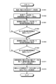
- FIG. 11 is a flowchart showing an example of a processing procedure by the storage battery internal state estimation method according to the first embodiment.
- step S1051 the data generation unit 5 acquires time-series data of current and voltage.
- the current time series data is acquired from the current detection device 3, and the voltage time series data is acquired from the voltage detection device 4.
- the data generation unit 5 calculates the higher-order calculus voltage data using the acquired data.
- the higher-order calculus voltage data is the differential data up to the ND order standardized by the normalized capacitance and the integral data up to the NIth order.
- the separation estimation unit 6 estimates the high-order element function using the higher-order differential voltage data among the higher-order calculus voltage data.
- step S1062 it is confirmed whether or not all the high frequency element functions have been estimated. If all the high frequency element functions have not been estimated (steps S1062 and No), the process returns to step S1061 and the processes of steps S1061 and S1062 are repeated. If all the high frequency element functions have been estimated (steps S1062 and Yes), the process proceeds to step S1063.
- a typical process of step S1061 is a step of estimating an element function including at least one higher-order high-order element function from data including higher-order higher-order differentials, based on higher-order higher-order differential data. It repeats sequentially to lower-order differential data.
- the parameters of the approximate function that approximates the function that has not been estimated yet may be estimated at the same time, or the parameters of the element function estimated in the past may be used.
- the separation estimation unit 6 estimates the low frequency element function using the higher-order integrated voltage data among the higher-order calculus voltage data.
- step S1064 it is confirmed whether or not all the low frequency element functions have been estimated. If all the low frequency element functions have not been estimated (steps S1064 and No), the process returns to step S1063, and the processes of steps S1063 and S1064 are repeated. Further, if all the low frequency element functions have been estimated (step S1064, Yes), the process proceeds to step S1071.
- step S1063 is to estimate the element function including at least one lower-level low-frequency element function from the data including the higher-order higher-order integral, from the higher-order higher-order integral data. Iterates in order to lower-order integral data.
- the parameters of an approximate function that approximates a function that has not been estimated yet may be estimated at the same time, or the parameters of a previously estimated element function including a high-frequency element function may be used.
- the integrated estimation unit 7 estimates the parameters of the storage battery voltage function using the voltage data including the higher-order calculus voltage.
- the parameter of the storage battery voltage function is estimated by using the parameter of the element function estimated so far as the initial value of the parameter of the storage battery voltage function.
- the storage battery voltage function is typically expressed by the sum of the high-frequency element function or the low-frequency element function, but there are element functions that do not belong to either the high-frequency element function or the low-frequency element function. You may. That is, there may be an element function in which the parameters are not estimated in steps S1061 and S1063, and the parameters are estimated for the first time in step S1071.
- the deterioration diagnosis unit 8 estimates the deterioration parameter by comparing two or more storage battery data. Specifically, parameters including deterioration parameters included in the storage battery voltage function are estimated so that the error from the higher-order differential voltage data of the reference storage battery becomes small.
- steps S1061 and S1062 that repeat the estimation of the high-frequency element function and the processing of steps S1063 and S1064 that repeat the estimation of the low-frequency element function may be in the reverse order. Also, processing of both of these sets is not always necessary. Further, it is not necessary to separately perform the estimation process of the high frequency element function and the estimation process of the low frequency element function in a single block. For example, after separating and estimating one high-frequency element function, one low-frequency element function may be estimated before estimating another high-frequency element function.
- Embodiment 2 the storage battery internal state estimation device and the storage battery internal state estimation method according to the second embodiment will be described. However, the description of the portion described in the first embodiment will be omitted as appropriate.
- FIG. 12 is a diagram showing a configuration example of the storage battery deterioration diagnosis system 100A including the storage battery internal state estimation device 1A according to the second embodiment.
- the storage battery internal state estimation device 1A according to the second embodiment has an information acquisition unit 9 added to the configuration of the storage battery internal state estimation device 1 according to the first embodiment shown in FIG.
- Other components are the same as or equivalent to those shown in FIG. 1, and the same or equivalent components are designated by the same reference numerals as those shown in FIG.
- the separation estimation unit 6, the integrated estimation unit 7, and the deterioration diagnosis unit 8 of the second embodiment can perform the above-mentioned processing by using the information regarding the storage battery acquired from the information acquisition unit 9.
- the information acquisition unit 9 has acquired information about the storage battery 2 in advance.
- the information acquisition unit 9 provides the acquired information to the separation estimation unit 6, the integrated estimation unit 7, and the deterioration diagnosis unit 8 so that it can be used for the deterioration diagnosis of the storage battery 2.
- the information here includes the relationship between the open circuit voltage and the charge amount in a standard storage battery, typically a new storage battery, the relationship between the open circuit potential of the positive electrode and the charge amount of the positive electrode, and the charge using the positive electrode in a new storage battery cell. It includes the amount region, the relationship between the open circuit potential of the negative electrode and the charge amount of the negative electrode, the charge amount region used by the negative electrode in a new storage battery cell, and information on their functions.
- this information may include information on the internal resistance of the positive electrode and the negative electrode. Further, when the active material of at least one of the positive electrode and the negative electrode is composed of a plurality of active materials, the above-mentioned information may be possessed for each of the plurality of active materials.
- the information acquisition unit 9 may acquire the information from an external information source, or may have the information in advance.
- the voltage curve of the storage battery 2 can be fitted by using the charge amount, capacity retention rate, and internal resistance of the storage battery in each of the possessed positive electrode potential curve and negative electrode potential curve as variables.
- the parameters that characterize the deterioration with respect to the differential voltage curve and the differential capacitance curve it is possible to perform a detailed deterioration diagnosis of the storage battery 2.
- This kind of method is disclosed in, for example, Japanese Patent No. 588548 "Battery Deterioration Calculator" or the above-mentioned Patent Document 1, that is, Japanese Patent No. 6123844 "Secondary Battery Capacity Measuring System and Secondary Battery Capacity Measuring Method". Has been done.
- the voltage curve at the time of charging / discharging is also affected by hysteresis according to the past charging / discharging history and the amount of charge at the start of charging / discharging.
- hysteresis due to the influence of hysteresis, there is a gap between the open circuit voltage and open circuit potential on the charging side and the open circuit voltage and open circuit potential on the discharging side. Due to this gap, qualitatively, it gradually approaches the open circuit voltage and open circuit potential on the charging side during charging, and gently approaches the open circuit voltage and open circuit potential on the discharging side during discharging. Therefore, the voltage curve is directly affected by this.
- the function parameters and deterioration parameters are estimated while improving the SN ratio and reducing the estimation parameters by appropriate separation estimation.
- the voltage curve of the storage battery 2 is fitted by using at least one of the higher-order differential data and the higher-order integral data as well as the voltage data. This makes it possible to amplify or attenuate the high-frequency component or the low-frequency component of the voltage curve to improve the accuracy and stability of the parameter estimation as described in the first embodiment. Further, by using the higher-order differential voltage data, the asymptotic curve with a gentle hysteresis becomes attenuated by the higher-order differential, and the estimation of the function parameter and the deterioration parameter becomes easier.
- the information acquisition unit 9 when the information acquisition unit 9 has the function parameters, at least one of the separation estimation unit 6 and the integrated estimation unit 7 can be omitted.
- the time-series data for estimation uses a higher-order calculus based on the capacity of the voltage, that is, a higher-order calculus voltage obtained by differentiating or integrating the voltage by the capacity. That is, it is also possible to use a higher-order calculus capacity obtained by differentiating or integrating the capacity with a voltage. Further, both the higher-order calculus voltage and the higher-order calculus capacity may be used.
- the horizontal axis is voltage, so unlike the case of higher-order calculus voltage, it is not necessary to estimate the normalized capacity even if the normalized capacity has an error. Yes, instead, the overvoltage due to the internal resistance should be estimated. Since the components to be amplified differ between the higher-order calculus voltage and the higher-order calculus capacitance, it may be easier to estimate when one is used than when the other is used.
- the parameter estimated using either one of the higher-order calculus voltage and the higher-order calculus capacity is used as the initial value, and the parameter can be re-estimated using the other or both.
- the capacitance function and the voltage function may be separately configured as the sum of the element functions, and both parameters may be estimated using the higher-order calculus capacitance data and the higher-order calculus voltage data.
- the calculus voltage has been used, but since the differentiation is included in the high-pass filter (HPF) and the integration is included in the low-pass filter (LPF), it is more generalized among a plurality of HPFs and LPFs. At least one may be used for processing.
- the "higher-order derivative" in the above description corresponds to the "HPF that amplifies higher frequencies more”.
- the "higher-order integral” corresponds to the "LPF that amplifies lower frequencies more”.
- fractional calculus which is an arithmetic process including the calculus of the non-integer order
- the fractional calculus it becomes possible to extract or attenuate a specific element function more flexibly.
- the above equation (40) is an equation called Caputo differentiation.
- Caputo differentiation the operation of integrating the ⁇ -th order fractional order with respect to the function obtained by differentiating the integer order of the n ⁇ order is performed.
- fractional derivative includes “integer calculus”
- fractional integral also includes “integer calculus”.
- Z Dj is a positive real number
- Z Dk ⁇ 1 for at least one k.
- Z Ij is a positive real number.
- fractional derivative When fractional derivative is used for the voltage curve, it is included in the voltage curve by amplifying the high frequency component of the voltage curve derived from the characteristics such as the phase change of the electrode material and amplifying the low frequency component. It is possible to improve the SN ratio of the high frequency component. This facilitates the estimation of the battery model function. Moreover, by using not only the voltage curve but also the fractional derivative curve, the validity of the estimation result can be confirmed more accurately. For example, even if the model function has a small error for the voltage curve, there may be a sufficient number of estimation failures in which the error is large for the fractional-order differential voltage curve.
- the fractional integral When the fractional integral is used for the voltage curve, it is included in the voltage curve by amplifying the low frequency component of the voltage curve derived from the characteristics such as the phase change of the electrode material and amplifying the high frequency component. It is possible to improve the SN ratio of the low frequency component. This facilitates the estimation of the model function of the storage battery. Further, as in (1), the validity of the estimation result can be confirmed more accurately.
- Z Dj is a positive real number
- Z Dk ⁇ 1 for at least one k.
- Z Ij is a positive real number.
- Z D1j , Z D2j , Z I1j and Z I2j are positive real numbers, Z D1j is Z D1k ⁇ 1 for at least one k, and Z D2j is Z D2k ⁇ 1 for at least one k. be.
- the deterioration parameter of the storage battery may be estimated by relative comparison with the time series data of one or more integer storage batteries acquired in the past. As a result, deterioration diagnosis can be performed without having to possess data on the relationship between the electrode potential and the electrode capacitance in advance.
- the deterioration diagnosis can be performed.
- at least one of the high-frequency component and the low-frequency component contained in the data is used because at least one of the data of the Z-th order differential curve and the Z-th order integral curve other than the original curve or the first-order differential curve is used.
- One SN ratio can be improved. This makes it possible to improve the estimation accuracy and the stability of the estimation calculation, and increase the probability of convergence to the optimum value.
- the model function may be further expressed as the sum of the element functions.
- separation estimation such that a relatively high-frequency element function is estimated from the fractional-order differential data and a relatively low-frequency element function is estimated from the fractional-order integral data.
- the number of parameters to be estimated at one time is reduced, the components that are not estimated are attenuated, and the components to be estimated are amplified, which facilitates the estimation of the model function.
- a function including a position parameter ⁇ and a scale parameter ⁇ may be used for each of the high frequency element function and the low frequency element function.
- At least one of the high frequency element function and the low frequency element function is the distortion sigmoid function represented by the above equation (13) or the distortion represented by the above equation (14).
- a peak function may be used.
- the operation of estimating the higher-frequency high-frequency element function by using the higher-order Z-th derivative curve is repeated in order, and the higher-order Z-th order is repeated.
- the operation of estimating the lower frequency element function may be repeated in order using the integral curve. Then, when estimating a certain high-frequency element function or low-frequency element function, the already-estimated high-frequency element function and low-frequency element function may be subtracted. This makes it possible to emphasize the high-frequency or low-frequency components one by one by high-order calculus without estimating all the element functions at once. Further, at the time of estimation, the influence of the higher-frequency or lower-frequency component is removed by using the past estimation results, so that the estimation becomes easy.
- the estimated parameters of the high-frequency element function and the low-frequency element function are used, for example, as initial values for estimation, and the model function of the storage battery is estimated again.
- the estimation can be started from the parameter value having a high probability of being close to the optimum value, and the estimated value of the parameter with high accuracy can be obtained.
- an element function that has not been estimated yet particularly an element function attenuated by a higher-order calculus, may be replaced with an approximate function for estimation. This facilitates the estimation of the element function to be estimated.
- this processing is performed, the number of parameters is reduced compared to the case where the attenuated element function is estimated at the same time without replacing it with the approximation function, and conversely, the approximation function is used rather than the case where only the element function to be estimated is estimated.
- the model will be more accurate. Therefore, it is possible to estimate the parameters with higher accuracy.
- a high frequency element function may be used for one electrode function, and a low frequency element function may be used for the other electrode function.
- the estimation of the high frequency element function by the fractional derivative data estimates one electrode function
- the estimation of the low frequency element function by the fractional calculus data estimates the other electrode function.
- the positive and negative functions can be separated and estimated.
- each element function estimated based on the time-series data for estimation and the parameters of each estimated element function.
- the parameters of the model function may be estimated again by setting the parameters as initial values. By doing so, the estimation can be started from the parameter value having a high probability of being close to the optimum value, and the estimated value of the parameter with higher accuracy can be obtained.
- the configuration shown in the above embodiments is an example, and can be combined with another known technique, or can be combined with each other, and deviates from the gist. It is also possible to omit or change a part of the configuration to the extent that it does not.
- 1,1A storage battery internal state estimation device 2 storage battery, 3 current detection device, 4 voltage detection device, 5 data generation unit, 6 separation estimation unit, 7 integrated estimation unit, 8 deterioration diagnosis unit, 9 information acquisition unit, 40 controller, 60 estimation unit, 100, 100A storage battery deterioration diagnosis system, 400 processor, 401 storage device.
Landscapes
- Physics & Mathematics (AREA)
- General Physics & Mathematics (AREA)
- Engineering & Computer Science (AREA)
- Manufacturing & Machinery (AREA)
- Chemical & Material Sciences (AREA)
- Chemical Kinetics & Catalysis (AREA)
- Electrochemistry (AREA)
- General Chemical & Material Sciences (AREA)
- Power Engineering (AREA)
- Secondary Cells (AREA)
- Tests Of Electric Status Of Batteries (AREA)
Abstract
蓄電池内部状態推定装置(1)は、データ生成部(5)と、推定部(60)とを備える。データ生成部(5)は、蓄電池(2)から取得した電流値及び電圧値の時系列データから推定用時系列データを生成する。推定部(60)は、推定用時系列データに基づいて蓄電池(2)のモデル関数を推定する。推定用時系列データは、1以上の整数であるND個のZDj(j=1,…,ND)階微分電圧曲線を含み、ZDjは正の実数であり、少なくとも1つのkに対してZDk≠1である。
Description
本開示は、蓄電池の内部状態を推定する蓄電池内部状態推定装置及び蓄電池内部状態推定方法に関する。
環境負荷低減のため、EV(電気自動車:Electric Vehicle)、HEV(ハイブリッド電気自動車:Hybrid Electric Vehicle)、PHV(プラグインハイブリッド自動車:Plug-in Hybrid Vehicle)などの電動車両が実用化されている。また、電動航空機などの開発も進んでいる。更には、再生可能エネルギーの活用のための定置用蓄電システムも普及している。
これらの機器には、リチウムイオン電池などの蓄電池が用いられている。蓄電池は使用と共に劣化が進行し、性能が低下することが知られている。これらの蓄電池の性能及び交換時期の把握、並びに蓄電池の寿命予測のためには、蓄電池の劣化診断を行うことが必要となる。
蓄電池の劣化診断方法として、下記特許文献1には、微分電圧曲線を利用する手法が開示されている。この手法の実施手順は、以下の通りである。始めに、蓄電池の正極材料及び負極材料の電気特性から得られる微分電圧曲線を事前に取得する。次に、この微分電圧曲線にフィットするフィッティング関数と、このフィッティング関数のパラメータとを計算で求める。最後に、使用中の蓄電池の実測値から得られる微分電圧曲線におけるピークの位置、ピークの高さ、ピークの幅などから算出されるフィッティング関数のパラメータの変動に基づいて劣化診断を行う。
従来の手法において、事前に取得した蓄電池の正極材料及び負極材料の電気特性から得られる正極電圧曲線及び負極電圧曲線は、多くの場合、横軸を電極充電率とした電極充電率-電圧曲線の形状が変化しないという暗黙の仮定がなされている。そして、この仮定に基づき、正極及び負極の横軸を電極充電量として予め取得した電極容量-電圧曲線をそれぞれ縮小させたり、左右にシフトさせたりすることで、異なる劣化モードを定量的に推定しつつ、劣化した蓄電池セルの容量-電圧曲線をモデル化する。しかしながら、現実には、電極容量-電圧曲線の形状は変化し、電圧の局所的な変動が緩やかになっていく現象が観測される。即ち、電極容量-電圧曲線の形状は、微分電圧曲線でみたときのピークがなだらかになっていくことが多い。この現象は、蓄電池が劣化するにつれ、電極を構成する多数の粒子の間の劣化度にばらつきが生じたり、各粒子と集電体との間の導電パスが途切れそうになったりすることで、充放電時の粒子ごとの充電率にばらつきが生じるためと考えられる。それ故、予め取得した蓄電池の特性情報をそのまま用いるのではなく、劣化に応じた電圧曲線又は微分電圧曲線の形状変化を反映できるような蓄電池電圧曲線のモデル化による精度の良い劣化診断技術が求められている。
本開示は、上記に鑑みてなされたものであって、診断対象となる蓄電池の特性情報がない場合でも精度の良い劣化診断ができる蓄電池内部状態推定装置を得ることを目的とする。
上述した課題を解決し、目的を達成するため、本開示に係る蓄電池内部状態推定装置は、データ生成部と、推定部とを備える。データ生成部は、蓄電池から取得した電流値及び電圧値の時系列データから推定用時系列データを生成する。推定部は、推定用時系列データに基づいて蓄電池のモデル関数を推定する。推定用時系列データは、1以上の整数であるND個のZDj(j=1,…,ND)階微分電圧曲線を含み、ZDjは正の実数であり、少なくとも1つのkに対してZDk≠1である。
本開示に係る蓄電池内部状態推定装置によれば、診断対象となる蓄電池の特性情報がない場合でも精度の良い劣化診断ができるという効果を奏する。
以下に添付図面を参照し、本開示の実施の形態に係る蓄電池内部状態推定装置及び蓄電池内部状態推定方法について詳細に説明する。なお、各図において、同一符号は同一又は同等部分を示している。
実施の形態1.
図1は、実施の形態1に係る蓄電池内部状態推定装置1を含む蓄電池劣化診断システム100の構成例を示す図である。蓄電池劣化診断システム100は、図1に示すように、蓄電池内部状態推定装置1と、蓄電池2と、電流検出装置3と、電圧検出装置4とを備える。実施の形態1に係る蓄電池内部状態推定装置1は、蓄電池2の内部状態を推定する装置である。内部状態の推定とは、蓄電池2の劣化状態の推定を含み、蓄電池2の劣化の程度及び進行状況、蓄電池2の容量低下の程度、並びに蓄電池2の劣化の程度の指標となる劣化パラメータの推定なども含む概念である。
図1は、実施の形態1に係る蓄電池内部状態推定装置1を含む蓄電池劣化診断システム100の構成例を示す図である。蓄電池劣化診断システム100は、図1に示すように、蓄電池内部状態推定装置1と、蓄電池2と、電流検出装置3と、電圧検出装置4とを備える。実施の形態1に係る蓄電池内部状態推定装置1は、蓄電池2の内部状態を推定する装置である。内部状態の推定とは、蓄電池2の劣化状態の推定を含み、蓄電池2の劣化の程度及び進行状況、蓄電池2の容量低下の程度、並びに蓄電池2の劣化の程度の指標となる劣化パラメータの推定なども含む概念である。
診断対象のリチウムイオン電池の例は、正極にNMC系の材料、負極にグラファイトを使用したリチウムイオン電池である。なお、診断対象の蓄電池2には、他の材料系で構成されるリチウムイオン電池に加え、正極と負極とを有し、かつ充電及び放電が可能な一般的な蓄電池が含まれていてもよい。また、診断対象の蓄電池2は、リチウムイオン電池の他に、鉛蓄電池、ニッケル水素蓄電池、全固体蓄電池などでもよい。また、診断対象の蓄電池2は、単一セルの蓄電池の他に、複数のセルが直列接続された蓄電池モジュール、又は複数のセルが並列接続された蓄電池モジュールでもよい。更に、診断対象の蓄電池は、複数のセルの直列接続と並列接続とが組み合わされて構成された蓄電池モジュールでもよい。また、単一の蓄電池モジュールが複数並列に接続された複数の蓄電池モジュールであってもよい。
次に、実施の形態1に係る蓄電池内部状態推定装置1の構成について、図1及び図2を参照して説明する。図2は、実施の形態1に係る蓄電池内部状態推定装置1のハードウェア構成の一例を示すブロック図である。
蓄電池内部状態推定装置1は、図1に示すように、データ生成部5と、推定部60とを備える。推定部60は、分離推定部6と、統合推定部7と、劣化診断部8とを備える。
図2には、蓄電池内部状態推定装置1のハードウェア構成の例が示されている。図2において、蓄電池内部状態推定装置1は、コントローラ40を備えている。コントローラ40は、プロセッサ400と、記憶装置401とを備えている。蓄電池内部状態推定装置1を構成する各部の機能、即ちデータ生成部5、分離推定部6、統合推定部7及び劣化診断部8の機能は、ソフトウェア、ファームウェア、又はそれらの組み合わせにより実現される。ソフトウェア及びファームウェアは、プログラムとして記述されており、記憶装置401に格納されている。プロセッサ400は、記憶装置401に記憶されたプログラムを読み出して、そのプグラムを実行することにより、蓄電池内部状態推定装置1の各部の機能を実現する。
図1の説明に戻る。電流検出装置3は、蓄電池2の電流を検出し、電流の時系列データをデータ生成部5に出力する。電圧検出装置4は、蓄電池2の電圧を検出し、電圧の時系列データをデータ生成部5に出力する。ここで、時系列データのサンプリング周期はts(秒)であるとする。
本明細書においては、特に明示しない限り、診断対象の蓄電池2は単一の蓄電池セルであり、また、単一の蓄電池セルは、単一セルのリチウムイオン電池である場合を想定した説明とする。なお、蓄電池2が複数の蓄電池である場合、電流検出装置3及び電圧検出装置4は、それぞれ単位蓄電池ごとの電流及び電圧を検出するものであってもよい。その場合、以下の各部は、対象とする蓄電池2の数だけ同じ動作をすることになる。但し、単位蓄電池とは、蓄電池セルであってもよいし、蓄電池セルの直列接続又は並列接続の組み合わせによる蓄電池モジュールであってもよい。
<データ生成部5>
データ生成部5は、入力された電流値Iと、サンプリング周期tsとに基づいて、規格化容量のデータ点列を算出する。また、データ生成部5は、入力された電圧値Vと、規格化容量のデータ点列とに基づいて、電圧値Vを規格化容量でj(j=1,2,…,ND)階微分したND個の高階微分電圧のデータ点列を算出する。また、データ生成部5は、入力された電圧値Vと、規格化容量のデータ点列とに基づいて、電圧値Vを規格化容量でj(j=1,2,…,NI)階積分したNI個の高階積分電圧のデータ点列を算出する。最後に、データ生成部5は、電圧値V、規格化容量、ND個の高階微分電圧及びNI個の高階積分電圧のそれぞれのデータ点列を推定用時系列データとして生成する。生成された推定用時系列データは、推定部60に入力される。
データ生成部5は、入力された電流値Iと、サンプリング周期tsとに基づいて、規格化容量のデータ点列を算出する。また、データ生成部5は、入力された電圧値Vと、規格化容量のデータ点列とに基づいて、電圧値Vを規格化容量でj(j=1,2,…,ND)階微分したND個の高階微分電圧のデータ点列を算出する。また、データ生成部5は、入力された電圧値Vと、規格化容量のデータ点列とに基づいて、電圧値Vを規格化容量でj(j=1,2,…,NI)階積分したNI個の高階積分電圧のデータ点列を算出する。最後に、データ生成部5は、電圧値V、規格化容量、ND個の高階微分電圧及びNI個の高階積分電圧のそれぞれのデータ点列を推定用時系列データとして生成する。生成された推定用時系列データは、推定部60に入力される。
データ生成部5は、生成したデータ点列の一部又は全部を保存してもよく、かつ、現在取得又は生成したデータ点列と共に過去に保存したデータ点列の一部又は全部を出力してもよい。
データ生成部5で生成されるデータ点列は、以下の(1)式のように表すことができる。

但し、上記(1)式で記述されるデータ点列は、以下の(2)式のように定義されるものである。

上記(2)式において、kは離散時刻であり、診断のためにデータの取得を開始した時刻を0秒とし、サンプリング時刻をt秒とした場合、t=ts×kの関係が成り立つ。skは離散時刻kの規格化容量であり、Vk
(j)は離散時刻kの微分電圧、又は電圧、又は積分電圧である。また、このVk
(j)は、以下の(3)式のように定義される。
また、規格化容量skは、電気量(クーロン)の蓄積能力を表す容量qkにより、以下の(4)、(5)式を用いて算出することができる。


ここで、上記(5)式の分母にあるqtypは、規格化満充電容量である。規格化満充電容量qtypは、典型的には、診断対象の蓄電池2の定格満充電容量又は新品時の満充電容量を用いることができる。また、Xkは、離散時刻kにおけるXの値を意味する。また、規格化容量skは、規格化満充電容量qtypを基準としたときのサンプリングパラメータである離散時刻kにおけるSOC(充電状態:State Of Charge)である。規格化容量skを用いることで、定格満充電容量が異なる蓄電池、及び個体差もしくは劣化により満充電容量が低下した蓄電池を同じ基準で解析することが可能となる。なお、規格化容量skに替えて容量qkを用いてもよい。
また、蓄電池2の初期電気量q0は、蓄電池2のSOCと、OCV(開回路電圧:Open Circuit Voltage)との関係を利用して、以下の(6)、(7)式により算出することができる。


なお、上記(7)式における、qmaxは、蓄電池2の満充電容量である。満充電容量qmaxは、蓄電池2の満充電容量の推定値、又は規格化満充電容量qtypを用いることができる。また、関数fとしては、例えば、予め蓄電池2と同製品の蓄電池に対して通電と休止とを繰り返すことで取得した、SOCとOCVとの関係を表す複数のデータ点を、横軸をOCV、縦軸をSOCとして補間することにより取得されたものを用いることができる。或いは、初期電気量q0は、蓄電池2を搭載したシステムにおいて推定された蓄電池2のSOCの推定値であるSOCeから、以下の(8)式により算出してもよい。

電圧値V及び規格化容量skは、離散的なデータ点列である。このため、高階微分電圧Vk
(j)(j=1,…,ND)の算出には、これらの電圧値V及び規格化容量skの2点近似、3点近似、5点近似などのテーラー(Taylor)展開に基づく数値微分による近似微分を用いることができる。こうした近似微分を用いて微分電圧を算出する場合、取得した電流値I及び電圧値Vに含まれるノイズが増幅されるという問題がある。これを解決するために、取得した電流値I及び電圧値Vに対して、ローパスフィルタによるノイズ除去、又はフーリエ解析、ウェーブレット解析などによるノイズ除去を行なってもよい。ローパスフィルタとしては、移動平均フィルタ、Kolmogorov-Zurbenkoフィルタ、Savitzky-Golayフィルタ、アクティブフィルタ、パッシブフィルタなどの様々なフィルタ処理が知られている。
また、高階積分電圧Vk
(j)(j=-NI,…,-1)の算出方法としては、既知の台形公式、シンプソンの公式などを用いることができる。積分定数は、最も簡単には全てゼロとしてもよい。
このようにして生成されたデータ点列は、過去に生成されたデータ点列を含めて蓄電池内部状態推定装置1の内部の記憶装置401、又は蓄電池内部状態推定装置1の外部のデータサーバ、クラウドなどに保存されてもよい。
推定部60は、データ生成部5が取得して生成したデータ点列である推定用時系列データに基づいて、蓄電池2のモデル関数のパラメータを推定する。モデル関数のパラメータは、蓄電池2の劣化度の指標となる劣化パラメータを含んでいてもよい。推定部60は、典型的には、図1のように、分離推定部6と、統合推定部7と、劣化診断部8とを含んで構成されるが、推定部60の構成は、分離推定部6、統合推定部7及び劣化診断部8の全てを含むことを必須としない。
<分離推定部6>
分離推定部6は、データ生成部5が取得し生成したデータ点列に基づいて、高域関数及び低域関数のパラメータを推定する。高域関数は、相対的により高周波な成分が支配的な関数である。また、低域関数は、相対的により低周波な成分が支配的な関数である。
分離推定部6は、データ生成部5が取得し生成したデータ点列に基づいて、高域関数及び低域関数のパラメータを推定する。高域関数は、相対的により高周波な成分が支配的な関数である。また、低域関数は、相対的により低周波な成分が支配的な関数である。
ここで、ある関数をf(x)とすると、f(j)(x)は、jの値によりf(x)、又はf(x)の高階微分関数、又はf(x)の高階積分関数を表し、以下の(9)式のように定義されるものとする。

以下、高域関数を構成する要素となる関数を「高域要素関数」と呼び、低域関数を構成する要素となる関数を「低域要素関数」と呼ぶ。また、高域要素関数及び低域要素関数を総称して「要素関数」と呼ぶ。要素関数については、ロジスティック関数を例に具体的に説明する。ロジスティック関数はシグモイド関数の一種であり、以下の(10)式で表すことができる。

上記(10)式において、kは高さ、μは位置、σはスケールを表現するパラメータである。ここで言うスケールは、関数の緩やかさを意味する。上記(10)式を不定積分して定数項をゼロとすると、以下の(11)式で表される。

上記(11)式のように表現される関数は、ソフトプラス関数と呼ばれる。
また、上記(10)式を微分すると、以下の(12)式となる。

上記(12)式のように表現される関数は、ピーク関数と呼ばれる。
シグモイド関数及びその高階微積分による関数は、ガウシアン分布、コーシー分布、ハイパボリックセカント分布、スチューデントt分布、スチューデントz分布など、様々な確率分布の分布関数に基づいて表現することが可能である。
図3は、実施の形態1の提案手法で用いるロジスティック関数の二階微分から二階積分までの曲線をプロットした図である。横軸をx、縦軸をyとしたときに、図3(a)には、ロジスティック関数の二階積分関数であるy=f(-2)(x)が示されている。以下同様に、図3(b)にはロジスティック関数の一階積分関数であるy=f(-1)(x)が示され、図3(c)にはロジスティック関数であるy=f(x)が示されている。また、図3(d)にはロジスティック関数の一階微分関数であるy=f(1)(x)が示され、図3(e)にはロジスティック関数の二階微分関数であるy=f(2)(x)が示されている。これらの、二階積分から二階微分までの関数群は、y=f(j)(x)(j=-2,-1,0,1,2)と表すことができる。なお、図3の各波形は、ロジスティック関数f(x;k,μ,σ)におけるパラメータである、高さk、位置μ及びスケールσの値が、それぞれk=1、μ=0及びσ=1の場合を示している。
なお、図3(a)の二階積分関数y=f(-2)(x)には、破線で示すy=x2/2のグラフが重畳されている。また、図3(b)の一階積分関数y=f(-1)(x)には、破線で示すy=xのグラフが重畳されている。
元の関数y=f(x)はシグモイド関数であり、x=0からx=1に滑らかに移行している。一階微分関数y=f(1)(x)はピーク関数であり、x=0を中心に釣り鐘状の曲線となっている。二階微分関数y=f(2)(x)は、同じ高さの正負反対の山をもつ形状となっている。一方、一階積分関数y=f(-1)(x)はソフトプラス関数であり、x<0のときにx→-∞で0に漸近し、x>1のときにx→∞でy=xに漸近するような曲線となっている。これは、上記(11)式の第二項がx<<0のときに、log(1)に漸近し、x>>0のときに、xに漸近することから明らかである。また、一階積分関数y=f(-1)(x)はソフトプラス関数であり、二階積分関数y=f(-2)(x)は、一階積分関数y=f(-1)(x)を更に積分したものである。従って、二階積分関数y=f(-2)(x)は、x<0のときに、x→-∞で0に漸近し、x>1のときに、x→∞で定数Cを用いた二次関数y=x2/2+Cに漸近するような曲線となっている。
ここで、スケールσは、曲線の緩やかさを表現するパラメータである。このため、スケールσの値を小さくすれば、各曲線はより急峻になり、スケールσを大きくすれば各曲線はより緩やかとなる。言い換えれば、スケールσを相対的に小さくすれば、高周波成分が支配的な関数、即ち高域要素関数となる。また、スケールσを相対的に大きくすれば、低周波成分が支配的な関数、即ち低域要素関数となる。
図4は、実施の形態1の提案手法で用いるロジスティック関数におけるスケールσの値を変えたときの二階微分から二階積分までの曲線をプロットした図である。具体的に、実線はσ=1、破線はσ=2、一点鎖線はσ=0.5としたときのグラフである。図4の各図から明らかなように、スケールσを大きくすると曲線が緩やかとなる。即ち、スケールσを大きくすると、より低周波で大域的な関数となる。逆に、スケールσを小さくすると曲線が急峻となる。即ち、スケールσを小さくすると、より高周波で局在的な関数となる。
図5は、実施の形態1の提案手法で用いるロジスティック関数におけるスケールσの値を変えたときの二階積分から十階積分までの偶数階積分関数の曲線をプロットした図である。図5(a)には、ロジスティック関数の十階積分関数であるy=f(-10)(x)が示されている。以下同様に、図5(b)にはロジスティック関数の八階積分関数であるy=f(-8)(x)が示され、図5(c)にはロジスティック関数の六階積分関数であるy=f(-6)(x)が示されている。また、図5(d)にはロジスティック関数の四階積分関数であるy=f(-4)(x)が示され、図5(e)にはロジスティック関数の二階積分関数であるy=f(-2)(x)が示されている。これらの、偶数階積分関数からなる関数群は、y=f(j)(x)(j=-10,-8,-6,-4,-2)と表すことができる。なお、図5の各波形において、実線はσ=1、破線はσ=2、一点鎖線はσ=0.5としたときのグラフである。また、理解の容易性を得るため、各階数積分のグラフごとに、全ての関数値をf(j)(x)(10;σ=2)の値で割り、f(j)(x)(10;σ=2)=1となるように、関数値を正規化している。
図5のグラフから、積分階数が上がるにつれて、スケールσの値が最も大きい、σ=2の関数が支配的となっていっているのが確認できる。なお、前述したように、高さkはシグモイド関数の高さを決めるパラメータであり、位置μはピーク関数のピーク位置を決めるパラメータである。
なお、ピーク関数は、左右非対称な歪み(skewness)のあるピーク関数であってもよい。歪みのあるピーク関数の例として、歪み正規分布の密度関数が知られている。但し、歪み正規分布は、密度関数に誤差関数を含むと共に、分布関数は誤差関数とオーウェンのT関数とを含んでいる。このため、初等関数による解析解が得られないこれらの関数は、実用上は扱いにくい。
また、別の方法としてピーク位置の左と右とで、ピーク位置が一致するような別のピーク関数を用いることなども考えられるが、場合分けが生じるため、これもまた実用上は扱いにくい。
そこで、本開示に係る蓄電池内部状態推定装置1においては、新しい歪みシグモイド関数を提案する。詳細は後述するが、本開示に係る蓄電池内部状態推定装置1は、蓄電池2の微分電圧曲線のモデルとしてピーク関数を用いる。微分電圧曲線のモデルとしてピーク関数を用いる場合、電圧曲線のモデルとしても用いることができるように、ピーク関数と、ピーク関数の積分によるシグモイド関数とが初等関数で表現可能であることが望ましい。この条件を満たす関数として、本開示に係る蓄電池内部状態推定装置1では、以下の(13)式に示される歪みシグモイド関数を提案する。

歪みシグモイド関数が上記(13)式で表現されるとき、歪みシグモイド関数の微分による歪みピーク関数は、以下の(14)式のように表現することができる。

これらの新しい歪みシグモイド関数及び歪みピーク関数は、歪みパラメータνを調整することで歪み度を調整可能である。また、fは公知のシグモイド関数であり、f(-1)はその微分による公知のピーク関数である。このため、上記(14)式により、様々なシグモイド関数及びピーク関数を歪みシグモイド関数及び歪みピーク関数に変換することが可能である。
また、歪みピーク関数のピーク位置は、歪みにより公知のピーク関数のピーク位置μからずれていく。そこで、歪みピーク関数のピーク位置の導出を行う。歪みピーク関数のピーク位置をxmとすると、ピーク位置xmにおいては、xによる微分がゼロとなることから、以下の(15)式を解くことで解が求まる。

例えば、公知のピーク関数としてロジスティック関数を用いる場合は、以下の(16)式で表されるピーク位置xmが得られる。

同様に、他の関数を用いる場合においても、多くの例において、初等関数で表されるピーク位置の式が求まる。例えば、次式の(17)式で表されるハイパボリックセカント分布のピーク関数を用いた場合、次々式の(18)式で表されるピーク位置xmが得られる。


図6は、実施の形態1の提案手法により異なる6種類の分布の密度関数を用いて生成した歪みピーク関数に対して歪みパラメータνの値を少しずつ変動させたときの各νに対する曲線をプロットした図である。具体的に、図6(a)はガウス分布の例であり、図6(b)はハイパボリックセカント分布の例であり、図6(c)はロジスティック分布の例である。また、図6(d)はスチューデントt分布の例であり、図6(e)はコーシー分布の例であり、図6(f)はスチューデントz分布の例である。それぞれの例では、それぞれの分布の密度関数を上記(14)式のfとして歪みピーク関数を構成し、歪みパラメータνを徐々に大きくしていったときの曲線形状の変化がプロットされている。それぞれの図における破線は、ν=0のときの曲線を示している。
図6の各図を参照すると、何れも左右非対称なピーク関数が生成されている。また、何れも歪みパラメータにより歪み度を調整できていることが分かる。従って、上記(14)式を用いれば、左右非対称なピーク関数を生成することが可能である。
歪みピーク関数を構成する手法は他にも存在するが、上記(13)、(14)式を用いる手法には、以下の利点がある。
(i)公知のさまざまなシグモイド関数及びピーク関数から歪みピーク関数を構成可能であり、汎用性が高い。
(ii)歪みパラメータνを1つ追加するだけで歪みを表現可能であり、後述するパラメータ推定において有用である。
(iii)利用する公知のシグモイド関数が初等関数で表現可能であれば、歪みシグモイド関数及び歪みピーク関数も初等関数で表現可能であるため、実用上扱いやすく、特に蓄電池の電圧曲線と微分電圧曲線をモデル化するうえで有用である。
(iv)歪み関数のピーク位置の解析解が多くの場合に初等関数で求まるため、実用上有用であり、特に後述するパラメータ推定における初期値を決めるうえで有用である。
(ii)歪みパラメータνを1つ追加するだけで歪みを表現可能であり、後述するパラメータ推定において有用である。
(iii)利用する公知のシグモイド関数が初等関数で表現可能であれば、歪みシグモイド関数及び歪みピーク関数も初等関数で表現可能であるため、実用上扱いやすく、特に蓄電池の電圧曲線と微分電圧曲線をモデル化するうえで有用である。
(iv)歪み関数のピーク位置の解析解が多くの場合に初等関数で求まるため、実用上有用であり、特に後述するパラメータ推定における初期値を決めるうえで有用である。
以下、説明の簡易化及び理解の容易性の観点により、特に明記しない限り、通常のピーク関数を用いて説明する。なお、通常のピーク関数に代えて、公知ピーク関数、又は上記(14)式の歪みピーク関数を用いても同様の議論が可能であることは言うまでもない。
次に、要素関数と蓄電池2の電圧曲線との関係について説明する。まず、蓄電池2を定電流充放電するときの電圧値Vは、以下の(19)式で表される。

上記(19)式において、Upは正極電位、Unは負極電位、Iは蓄電池2に流れる電流、Rは蓄電池2の抵抗である。
次に、電極電位曲線を考える。一般的な蓄電池において、イオン濃度と電極電位との関係は、ネルンストの式で説明される。しかしながら、実際の電位曲線には、二層共存領域による平坦領域、相変化によるステップ状の変化、単相内へのイオンの挿入による線形に近い変化などが見られる。
図7は、NMC系の正極及びグラファイトの負極を備えた一般的なリチウムイオン電池における正極の電位曲線及び正極の微分電位曲線の一例を示した特性図である。図7において、横軸は正極の規格化容量であり、左の縦軸は電位、右の縦軸は微分電位である。実線は電位曲線、破線は微分電位曲線を表している。但し、通常、蓄電池セルの規格化容量0は負極電位で規制されるので、この特性図において、正極の規格化容量0付近は使用されない。図7から分かるように、NMCを始めとした多くの材料の正極電位曲線は、緩やかに電位変化する形状となっている。
ここで、正極の規格化容量をspとするとき、正極電位関数fp(sp)は、例えば、以下の(20)式で表すことができる。

また、上記(20)式を微分すると、以下の(21)式に示される正極微分電位関数fp
(1)(sp)が得られる。

上記(21)式のように、正極微分電位関数fp
(1)(sp)は、定数項と、np個のピーク関数と、mp個のシグモイド関数とを要素関数として、それらの和で表現されている。従って、(21)式を積分した関係にある上記(20)式に示される正極電位関数fp(sp)は、定数項と、線形項と、np個のシグモイド関数と、mp個のソフトプラス関数とを要素関数として、それらの和で表現される。
このように、シグモイド関数及びピーク関数を用いることで、電位曲線又は微分電位曲線の局所的な変化を良好に表現することができる。なお、上記(20)、(21)式の表現は一例であり、これらの要素関数に代えて、他の要素関数を用いてもよい。また、要素関数として、必ずしも高さk、位置μ、スケールσを表現するパラメータを含む関数を用いなければならないということではない。なお、図7の微分電圧曲線に関しては、定数項と、矢印A,Bの箇所のそれぞれに対応した2つのシグモイド関数により表現することが可能である。
図8は、図7に示すものと同じリチウムイオン電池における負極の電位曲線及び負極の微分電位曲線の一例を示した特性図である。図8において、横軸は負極の規格化容量であり、左の縦軸は電位、右の縦軸は正負を反転した微分電位である。実線は電位曲線、破線は微分電位曲線を表している。但し、通常、蓄電池セルの規格化容量1は正極電位で規制されるので、この特性図において、負極の規格化容量1付近は使用されない。
グラファイトである負極の電位曲線は、NMCである正極の電位曲線とは異なり、図8には、二層共存領域による平坦な曲線を描きつつも、所々で相変化によるシグモイド状の電位変化が示されている。この変化は、微分電位曲線でみると矢印で示す位置のピーク状の曲線に対応している。
ここで、負極の規格化容量をsnとするとき、負極電位関数fn(sn)は、例えば、以下の(22)式で表すことができる。

また、上記(22)式を微分すると、以下の(23)式に示される負極微分電位関数fn
(1)(sn)が得られる。

上記(23)式のように、負極微分電位関数fn
(1)(sn)は、mn個のピーク関数を要素関数として、それらの和で表現されている。従って、(23)式を積分した関係にある上記(22)式に示される負極電位関数fn(sn)は、定数項と、mn個のシグモイド関数とを要素関数として、それらの和で表現される。
図8の微分電位曲線においては、矢印の箇所にピーク関数を対応させることで精度良くモデル化することが可能となる。なお、正極の例と同様に、ここで用いた要素関数は一例であり、他の要素関数を用いてもよい。また、左端部における微分電圧の立ち上がりについては、ピーク関数でモデル化してもよいし、他の関数を要素関数として用いてもよい。例えば、シグモイド関数を用いてもよい。また、以下の(24)式に示されるような指数関数を用いてもよい。

蓄電池セルの電圧関数は、上記(19)式に従い、また、上記(20)、(22)式を用いて、以下の(25)式のように表すことができる。

上記(25)式において、各関数の引数は、蓄電池セルの規格化容量sとしている。また、fe,iはi番目の要素関数、θiはi番目の要素関数fe,iに含まれるパラメータのベクトルである。例えば、fe,i(s)=bpsのときはθi=bpであり、fe,i(s)=f(sn;kni,μni,σni)のときは、θi=[kni,μni,σni]Tである。
以上の説明のように、蓄電池セル電圧及び蓄電池セル微分電圧のモデル関数は、上述したソフトプラス関数、シグモイド関数及びピーク関数のうちの少なくとも1つを含む要素関数の和によって表現することが可能である。
<分離推定部6>
分離推定部6は、データ生成部5が取得して生成したデータ点列に基づいて、高域関数及び低域関数のパラメータを推定する。具体的には、以下のとおりである。
分離推定部6は、データ生成部5が取得して生成したデータ点列に基づいて、高域関数及び低域関数のパラメータを推定する。具体的には、以下のとおりである。
正極電圧曲線及び正極微分電圧曲線は、上記(20)、(21)式に示されるように、要素関数の和で表現される。このため、全ての関数のパラメータを一括で推定するのは得策ではない。そこで、実施の形態1では、少なくとも1つの特定の要素関数を増幅させ、他の要素関数を減衰させることで、他の要素関数を0又は近似関数に置き換えて、近似関数及び特定の要素関数のパラメータを推定する。この手法は、高階微分を行うと、より低域な要素関数がより減衰されるので、より高域な要素関数が抽出されるという性質、及び高階積分を行うと、より高域な要素関数がより減衰されるので、より低域な要素関数が抽出されるという性質を利用している。
より具体的に説明すると、以下の通りである。既に定義した関数f(j)(x;k,μ,σ)において、z=(x-μ)/σとおき、積分定数を全てゼロとすると、任意の整数jに対し、以下の(26)式に示す関係が成り立つ。

上記(26)式において、右辺にある引数をzとした関数f(j)(z;k)がxではなくzに関する微積分である点に注意すると、σ1<σ2のときは、以下の(27)式に示される関係が成り立つ。

また、σ1>σ2のときは、以下の(28)式に示される関係が成り立つ。

上記(27)、(28)式において、jの絶対値が大きいほど左辺と右辺の大小関係の差は大きくなる。つまり、σ1とσ2との間に大小関係がある限り、jを任意に大きくとることで、相対的に一方を減衰させ、相対的に他方を増幅させることが可能である。
なお、(27)、(28)式では、同じ関数を同じ階数だけ微積分した関数同士を比較しているが、これに限定されない。異なる関数を異なる階数だけ微積分した関数同士であっても、σ1とσ2との大小関係により、相対的に一方を減衰させ、相対的に他方を増幅させることは可能である。但し、2つの関数に対して微分又は積分を繰り返したときに、どちらの関数が相対的にどれだけ増幅又は減衰していくのかは、σ1とσ2との大小関係のみならず、2つの関数の形にも依存する。
さて、高階微積分によって特定の高域又は低域の領域のデータを抽出すると、抽出したデータとの誤差が小さくなるようにして、対応する要素関数のパラメータを推定する。その際、抽出した領域以外の減衰した成分に対応する要素関数についても、近似関数を用いてそのパラメータを同時に推定してもよい。例えば、定数で近似してもよいし、図3で説明したようなn次関数で近似したものを用いてもよい。即ち、近似関数の形に制限はない。
最終的な目的は、電圧関数によって、正極電位曲線と負極電位曲線とを分離しつつ、蓄電池セルの電圧曲線を精度よくモデル化することである。そのため、評価関数を用いて、評価関数の最小化を図る。最小化したい評価関数J0は、θi:=[θT
1,θT
2,…,θT
ne]Tとし、wjを重み係数としたときに、以下の(29)式のように表すことができる。

上記(29)式のように、電圧関数と電圧データそれぞれの高階微積分との差を評価関数に含めることで、SN比の向上が可能となる。なお、利用するデータの初期時刻及び終端時刻は、異なるjに対し異なる値としてもよい。また、ここでは簡単のため二乗誤差の和を用いているが、これに限定されない。評価関数は、多様な方法で記述することが可能である。
また、q階微積分でρ(q)番目の要素関数の抽出するときにおいて、最小化したい評価関数J1は、以下の(30)式で表されるものを用いることができる。

上記(30)式において、ρ(q)はq階微積分して抽出した要素関数のインデックスを表している。また、gqはq階微積分したときの減衰した要素関数の近似関数であり、δqは当該近似関数のパラメータを並べたベクトルである。なお、近似関数は必須ではなく、ゼロであってもよい。
上記(30)式による最小化の評価を繰り返すとき、1回目の評価関数は、以下の(31)式で表される。

上記(31)式において、qlは1回目の評価関数で用いられる微積分の階数を表わしている。また、hlはl-1回目までの推定結果に基づく関数であり、例えば、以下の(32)式で表すことができる。

上記(32)式において、θ*
ρ(qi)は評価関数Jiを最小化するようにして算出したθρ(qi)の推定値を表わしている。関数hlにより、過去に推定した関数を利用できる分、現在の推定計算をより高精度化したり、安定化したりすることが可能となる。また、典型的には、高い階数の微分データ又は積分データから順番に評価関数を作成して最小化する操作を繰り返していく。高階微分に関しては、より高域な高域関数は低い階数の微分データにおいてもより支配的であることが多い。このため、より高域な高域関数をより高階な微分で抽出し推定しておく処理とする。これにより、より低階な微分データにおけるより低域な高域関数の推定において、より高域な高域関数を差し引くことでその影響を除去することが可能となる。
同様に、高階積分に関しては、より低域な低域関数は低い階数の積分データにおいてもより支配的であることが多い。このため、より低域な低域関数をより高階な積分で抽出し推定しておく処理とする。これにより、低階な積分データにおけるより高域な低域関数の推定において、より低域な低域関数を差し引くことでその影響を除去することが可能となる。
上記(29)~(31)式の評価関数の最小化によるパラメータの推定手法としては、公知の非線形最適化手法を用いることが可能である。例えば、最適化手法として、ガウス-ニュートン法、レーベンバーグ-マーカート法などを用いることができる。なお、推定すべきパラメータに関し、何らかの情報、例えばあるパラメータが非負であるなどの情報が存在する場合がある。その場合には、これらの情報を制約条件として含めることで、最適化手法を制約条件付きの非線形最適化問題として定式化してもよい。この場合の最適化手法として、ペナルティ関数法、逐次二次計画法、GRG法(Generalized Reduced Gradient method)などを用いることができる。
なお、ここで挙げた制約条件なし及び制約条件ありの最適化手法は一例であり、他の最適化手法として、メタヒューリスティクスなどの最適化手法を用いてもよい。また、パラメータの数といった問題の規模、並びに処理速度及びメモリ量といった計算資源の規模に応じて最適化手法を使い分けてもよい。
また、上記(29)~(31)式では、評価関数を二乗誤差の和で構成しているが、評価関数の構成方法はこれに限らない。例えば、二乗誤差の和ではなく、n≠2であるnによるn乗誤差の和で構成してもよい。或いは、正則化項などを含めた重み付き和で構成してもよい。
<統合推定部7>
統合推定部7は、分離推定部6で推定したパラメータに基づき、上記(23)式を最小化するようにしてパラメータを改めて推定する。具体的には、分離推定部6で別々に求めたパラメータ及び分離推定部6で求めなかったパラメータのうちの少なくとも何れかを含め、かつ、既に推定したパラメータをここでの推定の初期値として利用して、全パラメータを改めて推定する。
統合推定部7は、分離推定部6で推定したパラメータに基づき、上記(23)式を最小化するようにしてパラメータを改めて推定する。具体的には、分離推定部6で別々に求めたパラメータ及び分離推定部6で求めなかったパラメータのうちの少なくとも何れかを含め、かつ、既に推定したパラメータをここでの推定の初期値として利用して、全パラメータを改めて推定する。
分離推定部6は、一部の要素関数のみの推定を繰り返している。この繰り返し処理では、高階微積分により減衰した他の要素関数をゼロとしたり、近似関数で置き換えたりすることで、パラメータを推定している。このため、こうした近似処理の影響で推定パラメータが誤差を含んでいる可能性があった。そこで、統合推定部7は、推定済みのパラメータを集めて全パラメータ及び全要素関数を統合して蓄電池電圧関数のパラメータを改めて推定する処理を行う。この推定処理では、分離推定部6で既に推定したパラメータを初期値とするので、統合推定部7での推定結果が最適値に近い値に収束する蓋然性が高くなる。従って、統合推定部7での処理により、推定近似による誤差の小さい推定結果を得ることができる。
以上のようにして、蓄電池2の電圧関数を精度良く求めることが可能となる。また、正極電位曲線と負極電位曲線との間に形状の違いがあるときでも、高階微積分を利用して分離しつつ、別々にそれぞれの関数を推定することが可能となる。
図9は、実施の形態1の提案手法を用いて行った高階微分による分離及び推定の一例を示す図である。図9(a)には、蓄電池電圧の一階微分電圧の部分データ及びそれに対する推定結果が示されている。図9(b)には、蓄電池電圧の二階微分電圧の部分データ及びそれに対する推定結果が示されている。両図において、破線は正極の関数、一点鎖線は負極の関数、実線は蓄電池セルの関数の推定結果を表わしている。なお、部分データは白丸で表しているが、プロット間隔が狭いため、両図ではほぼ太線になっている。図9に示す処理では、まず二階微分の部分データを用いて一部の関数パラメータの推定を行う。そして、その推定結果と、一階微分の部分データとに基づいて残りの関数パラメータの推定を行う。以下に、より具体的な処理手順を説明する。
二階微分データに対しては、上記(30)式を最小化する処理を行う。まず、上記(30)式に示される関数を、q=2に対し、以下の(33)式のように設定する。

上記(33)式において、θρ(q)=[k,μ,σ,ν]であり、δq=dである。この(33)式において、正極電圧曲線に由来する低域成分は、二階微分においては十分に減衰している。このため、定数項dを近似関数として近似表現している。一方、高階微分においては、高域成分は強調されており、高精度なモデル化が重要となる。このため、高域関数を歪みシグモイド関数として、その二階微分を用いている。特に、図9は、負極にグラファイトを用いた蓄電池である。この蓄電池の場合、グラファイトの中間容量における微分電位のピークは図8のように非対称な形状となる。このため、歪みパラメータを用いた表現が重要となる。
このようにして、二階微分電圧データのみに対して推定処理を行う。これにより、より少数のパラメータをまず推定することとなり、推定の難易度が下がる。その結果、パラメータをより高精度かつ安定的に推定することが可能となる。
なお、ここでの推定処理では二階微分電圧を用いているが、より高階な微分電圧データを用いてもよい。その場合、二階微分データに対し正極電位関数に由来する低域成分を定数で近似できるのであれば、三階以上微分したデータに対しては、低域成分は0と近似してよいことになる。但し、一般的に、より高階な微分になるほどノイズも増幅されるので、フィルタリングなどによるより繊細な前処理が求められるようになる。それ故、微分の階数は、より低域な成分を減衰させる効果と、ノイズを増幅させる効果とのトレードオフを考慮して決めることが望ましい。
次に、二階微分データに対して推定したパラメータに基づき、蓄電池セルの電圧関数を用いて、上記(29)式のJ0を最小化するようなθを推定する。
ここで、蓄電池セルの電圧関数は、以下の(34)式に示す関数を用いる。

そして、上記(34)式を用いて、θρ(q)=θ*
ρ(q)を関数fskewのパラメータの初期値としてθを推定する。また、近似関数gqのパラメータdも利用してもよい。例えば、(34)式の関数fがロジスティック分布のシグモイド関数であるとき、dがシグモイドの変曲点における傾きを近似していると仮定する。そして、変曲点であるs=μの点におけるf(1)の値と、dの推定値d*とを比較すると、以下の(35)式が導かれる。

上記(35)式に示されるように、k2の推定の初期値を4σ2d*とすることができる。
以上の説明のように、二階微分電圧データに対する推定結果を上記(29)式の評価関数を最小化するようなパラメータの推定における初期値として利用することで、上記(29)式の大域的最適解に近い点からパラメータ推定を開始することができる。この処理により、全パラメータが大域的最適解又はそれに近い点に収束する蓋然性が高くなる。また、上記(29)式においては、微分電圧データだけでなく二階微分電圧データのデータも用いているので、高域成分に対するSN比の向上を図ることができる。
なお、ここでの処理では、簡単のため、微分電圧データ及び二階微分電圧データのみを用いた説明としているが、電圧データ、又は二階微分電圧データ以外の高階積分電圧データを用いてもよい。例えば、低域成分を抽出するためには、高階積分データを用いればよい。
<劣化診断部8>
劣化診断部8は、2個以上の劣化度の異なる蓄電池2のデータを比較して、蓄電池2の劣化パラメータを推定する。劣化パラメータの推定には、過去に推定に用いたデータと、今回の推定に用いたデータとの両方を用いてもよい。或いは、今回の推定処理において、電流検出装置3及び電圧検出装置4が、それぞれ2個以上の蓄電池2の電流データ及び電圧データを検出しているのであれば、それぞれのデータ同士の比較により、相対的な劣化度を推定してもよい。この場合には、データ生成部5、分離推定部6、統合推定部7においても、これまでに説明してきた内容を複数の蓄電池データに対して適用することになる。
劣化診断部8は、2個以上の劣化度の異なる蓄電池2のデータを比較して、蓄電池2の劣化パラメータを推定する。劣化パラメータの推定には、過去に推定に用いたデータと、今回の推定に用いたデータとの両方を用いてもよい。或いは、今回の推定処理において、電流検出装置3及び電圧検出装置4が、それぞれ2個以上の蓄電池2の電流データ及び電圧データを検出しているのであれば、それぞれのデータ同士の比較により、相対的な劣化度を推定してもよい。この場合には、データ生成部5、分離推定部6、統合推定部7においても、これまでに説明してきた内容を複数の蓄電池データに対して適用することになる。
図10は、実施の形態1の提案手法の説明で用いる蓄電池セルの電圧関数に反映させる劣化モードの説明に供する図である。図10には、蓄電池セルの電圧であるセル電圧と正極電位と負極電位との関係が示されている。蓄電池セルは、リチウムイオン電池である。図10(a)は蓄電池セルが新品である場合の例であり、図10(b)は蓄電池セルが正極劣化を起こした場合の例である。また、図10(c)は蓄電池セルが負極劣化を起こした場合の例であり、図10(d)はリチウム消費劣化を起こした場合の例である。
図10(a)の特性を見ると、セル電圧の下限はほぼ負極電位に規定されており、正極はまだ充電に余裕があるのに対し、セル電圧の上限はほぼ正極電位に規定されており、負極はまだ充電に余裕があることが分かる。
正極劣化が生じると、図10(b)のように、正極容量の低下によって正極電位曲線が左に縮小し、セル電圧曲線もその影響を受ける。同様に、負極劣化が生じると、図10(c)のように、負極容量の低下によって負極電位曲線が左に縮小し、セル電圧曲線もその影響を受ける。なお、正極容量は正極電極における満充電容量であり、負極容量は負極電極における満充電容量である。
また、リチウム消費劣化が生じると、図10(d)のように、正極電位曲線が相対的に左にシフトし、セル電圧曲線もその影響を受ける。正極電位曲線が相対的に左にシフトするのは、充電時に負極から放出されたリチウムイオンが正極に全て受け渡されず、負極SEI(Solid-Electrolyte Interface)の成長、リチウムの析出などの副反応で消費されるためと考えられる。
また、上記以外にも、蓄電池セルの抵抗が増大する劣化モードも存在する。厳密には、抵抗増大の要因として、接触抵抗、電解液抵抗、正極及び負極のそれぞれにおける反応抵抗、拡散抵抗など、様々なものが考えられるが、ここでは簡単のため、これらを総称して蓄電池セルの抵抗の増大とする。
以上の説明を纏めると、蓄電池セルの劣化モードは、大別して正極容量劣化、負極容量劣化、リチウム消費劣化及び蓄電池セル抵抗劣化という少なくとも4種類の劣化が存在する。
以上の劣化モードを踏まえると、劣化パラメータを反映した蓄電池セルの電圧関数は、以下の(36)式のように表現することができる。

上記(36)式において、s0は基準蓄電池の規格化容量であり、Φは劣化パラメータである。また、劣化パラメータΦは、Φ:=[φp,1,φp,2,φn,1,φn,2,φb]Tと定義される。ここで、φp,1は正極容量維持率を表し、φp,2はリチウム消費による正極電位曲線のずれを表している。また、φn,1は負極容量維持率を表し、φn,2は負極電位曲線のずれ及び診断時のセル規格化容量の推定誤差のうちの少なくとも1つを表している。また、φbは抵抗増加率を表している。
このとき、蓄電池2の劣化度を推定するための評価関数は、以下の(37)式で表される。

上記(37)式において、V(j)
0,kは、ある基準蓄電池データの離散時刻kにおけるj階微積分電圧データである。評価関数Jdを最小化するための手法は、既に述べた様々な方法が存在する。ここでは推定パラメータを劣化パラメータΦのみとしているが、fbの関数パラメータの一部を推定パラメータに含めて同時に推定してもよい。なお、ある基準蓄電池データとは、異なる劣化度の蓄電池のデータである。ある基準蓄電池データは、異なる時期に取得した同一の蓄電池のデータであってもよい。また、V(j)
0,kに変えて、V(j)
0,kを表現する蓄電池セルの電圧関数から算出した値を用いてもよい。
次に、実施の形態1に係る蓄電池内部状態推定方法による処理手順について、図11を参照して説明する。図11は、実施の形態1に係る蓄電池内部状態推定方法による処理手順の一例を示すフローチャートである。
まず、ステップS1051において、データ生成部5は、電流及び電圧の時系列データを取得する。電流時系列データは、電流検出装置3から取得し、電圧時系列データは、電圧検出装置4から取得する。
次のステップS1052において、データ生成部5は、取得データを用いて高階微積分電圧データを算出する。高階微積分電圧データは、規格化容量で規格化されたND階までの微分データと、NI階までの積分データである。
次のステップS1061において、分離推定部6は、高階微積分電圧データのうちの高階微分電圧データを用いて高域要素関数を推定する。
次のステップS1062では、全ての高域要素関数を推定したか否かが確認される。全ての高域要素関数が推定されていなければ(ステップS1062,No)、ステップS1061の処理に戻り、ステップS1061,S1062の処理を繰り返す。また、全ての高域要素関数が推定されていれば(ステップS1062,Yes)、ステップS1063に進む。
なお、ステップS1061の典型的な処理は、より高階な高階微分を含むデータから少なくとも1つのより高域な高域要素関数を含む要素関数を推定するというステップを、より高階な高階微分データからより低階な微分データへと順に繰り返していく。パラメータ推定時においては、まだ推定していない関数を近似した近似関数のパラメータを同時に推定したり、過去に推定した要素関数のパラメータを利用したりしてもよい。
次のステップS1063において、分離推定部6は、高階微積分電圧データのうちの高階積分電圧データを用いて低域要素関数を推定する。
次のステップS1064では、全ての低域要素関数を推定したか否かが確認される。全ての低域要素関数が推定されていなければ(ステップS1064,No)、ステップS1063の処理に戻り、ステップS1063,S1064の処理を繰り返す。また、全ての低域要素関数が推定されていれば(ステップS1064,Yes)、ステップS1071に進む。
なお、ステップS1063の典型的な処理は、より高階な高階積分を含むデータから少なくとも1つのより低域な低域要素関数を含む要素関数を推定するというステップを、より高階な高階積分データからより低階な積分データへと順に繰り返していく。パラメータ推定時においては、まだ推定していない関数を近似した近似関数のパラメータを同時に推定したり、高域要素関数を含む過去に推定した要素関数のパラメータを利用したりしてもよい。
次のステップS1071において、統合推定部7は、高階微積分電圧を含む電圧データを用いて蓄電池電圧関数のパラメータを推定する。典型的には、これまでに推定した要素関数のパラメータを、蓄電池電圧関数のパラメータの初期値として、蓄電池電圧関数のパラメータを推定する。但し、蓄電池電圧関数は、典型的には高域要素関数又は低域要素関数である要素関数の和によって表現されるが、高域要素関数にも低域要素関数にも属さない要素関数があってもよい。つまり、ステップS1061とステップS1063ではパラメータが推定されず、ステップS1071で初めてパラメータが推定されるような要素関数があってもよい。
最後のステップS1072において、劣化診断部8は、2個以上の蓄電池データの比較により、劣化パラメータを推定する。具体的には、基準蓄電池の高階微分電圧データとの誤差が小さくなるように、蓄電池電圧関数に含まれる劣化パラメータを含むパラメータが推定される。
なお、図11に示す処理の順序は一例であり、この順序に限定されない。例えば、高域要素関数の推定を繰り返すステップS1061,S1062の処理と、低域要素関数の推定を繰り返すステップS1063,S1064の処理とは、逆の順序であってもよい。また、これらの両方の組の処理が、必ず必要というわけでもない。また、高域要素関数の推定処理と、低域要素関数の推定処理とが、それぞれ別々に一塊で実施する必然性もない。例えば、ある高域要素関数を分離推定した後で、他の高域要素関数を推定する前に、ある低域要素関数を推定してもよい。
実施の形態2.
以下、実施の形態2に係る蓄電池内部状態推定装置及び蓄電池内部状態推定方法について説明する。但し、実施の形態1で説明済みの部分は、適宜説明を省略する。
以下、実施の形態2に係る蓄電池内部状態推定装置及び蓄電池内部状態推定方法について説明する。但し、実施の形態1で説明済みの部分は、適宜説明を省略する。
図12は、実施の形態2に係る蓄電池内部状態推定装置1Aを含む蓄電池劣化診断システム100Aの構成例を示す図である。実施の形態2に係る蓄電池内部状態推定装置1Aは、図1に示す実施の形態1に係る蓄電池内部状態推定装置1の構成において、情報取得部9が追加されている。その他の構成要素については、図1に示すものと同一又は同等であり、同一又は同等の構成要素には、図1と同一の符号を付している。
実施の形態2の分離推定部6、統合推定部7及び劣化診断部8は、情報取得部9から取得した蓄電池に関する情報を利用して上述した処理を実施することができる。
情報取得部9は、蓄電池2に関する情報を予め取得している。情報取得部9は、蓄電池2の劣化診断に利用できるように、分離推定部6、統合推定部7及び劣化診断部8に、取得した情報を提供する。ここでいう情報には、基準蓄電池、典型的には新品の蓄電池における開回路電圧と充電量との関係、正極の開回路電位と正極の充電量との関係、新品の蓄電池セルにおける正極使用充電量領域、負極の開回路電位と負極の充電量との関係、及び新品の蓄電池セルにおける負極使用充電量領域、それらの関数の情報などが含まれる。また、この情報には、正極及び負極の内部抵抗に関する情報が含まれていてもよい。更に、正極及び負極のうちの少なくとも1つの電極の活物質が複数の活物質で構成される場合、当該複数の活物質ごとに、上述の情報を保有していてもよい。情報取得部9は、外部の情報源から当該情報を取得してもよいし、当該情報を予め保有していてもよい。
こうした情報を予め保有しているとき、保有している正極電位曲線及び負極電位曲線におけるそれぞれの充電量、容量維持率、並びに蓄電池の内部抵抗を変数として、蓄電池2の電圧曲線をフィッティングしたり、微分電圧曲線及び微分容量曲線に対して劣化を特徴づけるパラメータを推定したりすることで、蓄電池2の詳細な劣化診断を行うことが可能である。この種の手法は、例えば特許第5889548号公報「電池劣化算出装置」、又は上述した特許文献1、即ち特許第6123844号公報「二次電池容量測定システム及び二次電池容量測定方法」などに開示されている。
しかしながら、これまでに説明してきたように、電圧曲線又は微分電圧曲線に用いられる複数の関数パラメータ及び劣化パラメータを一括で推定することは容易ではない。また、電圧曲線又は微分電圧曲線のみを用いることは、SN比の観点からある要素関数の推定には有利となり得ても、別の要素関数の推定には不利となり得る。例えば、電圧曲線においては、負極電位曲線に由来することの多い相変化による急峻な電位変化が見えづらい一方、微分電圧曲線においては、正極電位曲線に由来することの多い緩やかな電位変化、及び内部抵抗による直流に近い成分が減衰している。また、充放電時の電圧曲線は、過去の充放電履歴及び充放電開始時の充電量に応じてヒステリシスの影響も受ける。一般に、ヒステリシスの影響により、充電側の開回路電圧及び開回路電位と、放電側の開回路電圧及び開回路電位との間にはギャップが存在する。このギャップにより、定性的には、充電時には充電側の開回路電圧及び開回路電位に緩やかに漸近し、放電時には放電側の開回路電圧及び開回路電位に緩やかに漸近していく。このため、電圧曲線はこの影響を直接受けることになる。
そこで、本開示に係る蓄電池内部状態推定装置1Aにおいては、SN比を向上させつつ、適宜の分離推定により、推定パラメータを削減しつつ、関数パラメータ及び劣化パラメータの推定を行う。そして、電圧データだけでなく、高階微分データ及び高階積分データのうちの少なくとも何れかのデータを利用して、蓄電池2の電圧曲線をフィッティングする。これにより、電圧曲線の高域成分又は低域成分を増幅させたり、減衰させたりして、実施の形態1で説明したように、パラメータ推定の精度及び安定性を高めることが可能となる。また、高階微分電圧データを用いることで、ヒステリシスの緩やかな漸近曲線が高階微分により減衰したものとなり、関数パラメータ及び劣化パラメータの推定がより容易になる。
なお、実施の形態2の構成において、情報取得部9が関数パラメータを保有している場合、分離推定部6及び統合推定部7のうちの少なくとも1つは省略することが可能である。
以上、実施の形態1及び実施の形態2に係る蓄電池内部状態推定装置の構成及び動作について説明してきた。実施の形態1及び実施の形態2において、推定用時系列データは、電圧の容量による高階微積分、即ち電圧を容量で微分又は積分した高階微積分電圧を用いてきたが、容量の電圧による高階微積分、即ち容量を電圧で微分又は積分した高階微積分容量を用いることも可能である。また、高階微積分電圧及び高階微積分容量の両方を用いてもよい。電圧と容量の関係を高階微積分電圧曲線でみると、電圧が正極電位と負極電位との差で表せることから、正負極電位曲線の分離がしやすいという利点がある。一方、電圧と容量の関係を高階微積分容量曲線でみると、横軸が電圧のため、高階微積分電圧の場合とは異なり、規格化容量が誤差を有する場合にも規格化容量の推定が不要であり、代わりに内部抵抗による過電圧を推定すればよいことになる。高階微積分電圧と高階微積分容量とでは、増幅される成分が異なるため、一方を利用したほうが他方を利用するよりも推定し易いという場合がある。例えば、1階微分電圧dV/dsと、1階微分容量ds/dVとは逆数の関係となっているため、一方ではなだらかな変化が他方では急峻な変化になる、というように相補的な関係となる。故に、両方を適宜推定に利用することで、パラメータ推定を容易化することも可能である。具体的には、上記(29)式を変形した、以下の(38)式に示す評価関数を用いて、評価関数の最小化を図ることになる。

上記(38)式では、高階微積分容量に関する誤差の二乗和がλjで重みづけされて足し合わされている。なお、fb
-1(j)は、関数V=fb(s)の逆関数s=fb
-1(V)のj階微積分である。j階微積分fb
-1(j)が解析的に陽に求まらない場合でも、数値的に計算することが可能である。なお、高階微積分容量関数の方をs=fb(V)として表現し、高階微積分電圧関数をその逆関数V=fb
-1(s)として求めてもよい。劣化パラメータの推定における評価関数についても同様である。
なお、上記(38)式のようにせずとも、高階微積分電圧及び高階微積分容量のうちの何れか一方を用いて推定したパラメータを初期値として、他方又は両方を用いてパラメータを推定し直してもよい。或いは、容量関数と電圧関数とを別々に要素関数の和として構成しておいて、両方のパラメータを高階微積分容量データ及び高階微積分電圧データを用いて推定してもよい。
また、ここまでの説明では、微積分電圧を用いてきたが、微分はハイパスフィルタ(HPF)、積分はローパスフィルタ(LPF)に含まれることから、より一般化して、複数のHPF及びLPFのうちの少なくとも1つを用いて処理してもよい。この処理の場合、これまでの説明における「より高階な微分」は、「より高周波をより増幅するHPF」に対応する。また、「より高階な積分」は、「より低周波をより増幅するLPF」に対応する。HPF及びLPFのうちの少なくとも1つを用いることで、より自由度は高くなるが、HPF及び/又はLPFに通したあとの関数を初等関数で表現できないことが多い。従って、パラメータ推定における最適化計算の難易度が上がり、計算が複雑になる。
また、ここまで、整数階の微積分で説明してきたが、通常の整数階の微積分に加え、もしくは代えて、非整数階の微積分を含む演算処理である、いわゆる分数階微積分を用いてもよい。分数階微積分を用いることで、より柔軟に特定の要素関数を抽出したり、減衰させたりすることが可能となる。この場合にも、HPF及びLPFのうちの少なくとも1つを用いるときと同様の利点と欠点とがある。
以下の(39)式に、aを基点とする分数階積分を表すコーシーの公式を示す。

コーシーの公式を用いれば、分数階積分を効率的に計算することが可能である。コーシーの公式を用いると、n階積分の数値計算においてもn回積分計算を繰り返すことなく、コーシーの公式に従って1回積分計算をすることで値が求まるという意味で効率的である。また、コーシーの公式を用いれば、通常の整数階の積分も、同じ式で計算することが可能である。
また、α階分数階微分の場合は、幾つかの定義が存在する。例えば、αを自然数nαとし、0<β<1であるような実数βを用いてα=nα-βと書き直すと、以下の(40)式を用いて計算することができる。

上記(40)式は、Caputo微分と呼ばれる式である。上記(40)式を用いる場合、nα階の整数階微分した関数に対して、β階の分数階積分する操作を行うことになる。
なお、分数階微積分の定式化方法及び計算方法については、公知の分数階微積分学における知見を利用することが可能である。また、上記(39)、(40)式を厳密に計算できない場合、例えば、関数の積分結果が陽に求まらない場合、時系列データを微積分する場合などは、実施の形態1で説明したような様々な公知の近似微分及び近似積分を用いることが可能である。また、微分時におけるノイズ除去のために、フィルタリング技術などを用いることも可能である。
最後に、本明細書で開示した技術に関する有効性、即ち本明細書で開示した技術を用いることの効果について記述する。なお、以下の記述において、「分数階微分」との記載には「整数階微分」も含まれ、「分数階積分」との記載には「整数階積分」も含まれる。
電圧曲線に対し、「分数階微分」を用いる場合、推定用時系列データは、1以上の整数であるND個のZDj(j=1,…,ND)階微分電圧曲線を含む。ZDjは正の実数であり、少なくとも1つのkに対してZDk≠1である。また、電圧曲線に対し、「分数階積分」を用いる場合、推定用時系列データは、1以上の整数であるNI個のZIj(j=1,…,NI)階積分電圧曲線を含む。ZIjは、正の実数である。
(1)電圧曲線に対し、分数階微分を用いる場合、電極材料の相変化などの特性に由来する電圧曲線の高域成分を増幅させつつ、低域成分を減衰させることで、電圧曲線に含まれる高域成分のSN比を向上させることができる。これにより、電池のモデル関数の推定が容易化される。また、電圧曲線だけでなく分数階微分曲線も利用することで、推定結果の妥当性をより精確に確認できる。例えば、電圧曲線に対しては誤差の小さいモデル関数であっても、分数階微分電圧曲線に対しては誤差が大きいという推定失敗例は十分存在しうる。
(2)電圧曲線に対し、分数階積分を用いる場合、電極材料の相変化などの特性に由来する電圧曲線の低域成分を増幅させつつ、高域成分を減衰させることで、電圧曲線に含まれる低域成分のSN比を向上させることができる。これにより、蓄電池のモデル関数の推定が容易化される。また、(1)と同様に推定結果の妥当性をより精確に確認できる。
(3)電圧曲線に対し、分数階微分及び分数階積分の両方を用いる場合、分数階微分電圧曲線においては高域成分のSN比を向上させ、分数階積分曲線においては低域成分のSN比を向上させることができる。両方のSN比の向上により、電池のモデル関数の推定は更に容易化される。また、上記(1)、(2)と同様に推定結果の妥当性をより精確に確認することができる。また、分数階微分及び分数階積分の両方を用いるので、低域成分及び高域成分のうちの何れの成分の推定に失敗しているのかといった推定結果に関するより詳細な情報も得ることができる。
(4)容量曲線に対し、分数階微分を用いる場合も、上記(1)と同様の効果が得られる。
(5)容量曲線に対し、分数階積分を用いる場合も、上記(2)と同様の効果が得られる。
(6)容量曲線に対し、分数階微分及び分数階積分の両方を用いる場合も、上記(3)と同様の効果が得られる。
(5)容量曲線に対し、分数階積分を用いる場合も、上記(2)と同様の効果が得られる。
(6)容量曲線に対し、分数階微分及び分数階積分の両方を用いる場合も、上記(3)と同様の効果が得られる。
容量曲線に対し、「分数階微分」を用いる場合、推定用時系列データは、1以上の整数であるND個のZDj(j=1,…,ND)階微分容量曲線を含む。ZDjは正の実数であり、少なくとも1つのkに対してZDk≠1である。また、容量曲線に対し、「分数階積分」を用いる場合、推定用時系列データは、1以上の整数であるNI個のZIj(j=1,…,NI)階積分容量曲線を含む。ZIjは、正の実数である。
(7)電圧曲線及び容量曲線の両方に対し、分数階微分及び分数階積分の両方を用いる場合、電圧曲線、容量曲線及びそれらの分数階微積分曲線には、既述の通り、モデル関数を推定する上で、長所もあるが短所もある。従って、電圧曲線に対して分数階微積分を用いる場合と、容量曲線に対して分数階微積分を用いる場合とを、長所及び短所を考慮して適宜に採用すれば、一方のみでは推定難易度が高いパラメータであっても、精度のよい推定が可能となる。
また、電圧曲線及び容量曲線の両方に対し、分数階微分及び分数階積分の両方を用いる場合、推定用時系列データには、1以上の整数であるND1個のZD1j(j=1,…,ND1)階微分電圧曲線と、1以上の整数であるND2個のZD2j(j=1,…,ND2)階微分容量曲線と、1以上の整数であるNI1個のZI1j(j=1,…,NI1)階積分電圧曲線と、1以上の整数であるNI2個のZI2j(j=1,…,NI2)階積分容量曲線とが含まれる。ZD1j、ZD2j、ZI1j及びZI2jは正の実数であり、ZD1jは少なくとも1つのkに対してZD1k≠1であり、ZD2jは少なくとも1つのkに対してZD2k≠1である。
(8)上記(1)から(7)の何れかにおいて、更に、過去に取得した1以上の整数個の蓄電池の時系列データとの相対比較により、蓄電池の劣化パラメータを推定してもよい。これにより、電極電位と電極容量の関係データなどを予め保有しておかなくても、劣化診断が可能となる。
(9)また、上記(1)から(7)の何れかにおいて、更に、電極電位と電極容量との関係データなどを予め保有している場合には、劣化診断が可能となる。この例の場合、元の曲線又は1階微分曲線以外のZ階微分曲線及びZ階積分曲線のデータの少なくとも何れかを使用する分、データに含まれる高域成分及び低域成分のうちの少なくとも1つのSN比を改善できる。これにより、推定精度及び推定計算の安定性を向上させ、最適値への収束の蓋然性を高めることが可能となる。
(10)また、上記(1)から(7)の何れかにおいて、更に、モデル関数を要素関数の和として表わすようにしてもよい。このようにすることで、分数階微分データから相対的に高域な要素関数を推定し、分数階積分データから相対的に低域な要素関数を推定するというような分離推定が可能となる。これにより、一度に推定するパラメータ数が削減されつつ、推定しない成分が減衰され、推定したい成分が増幅されることで、モデル関数の推定が容易化される。
(11)上記(10)において、更に、高域要素関数及び低域要素関数のそれぞれに位置パラメータμと、スケールパラメータσとを含む関数を用いるようにしてもよい。このようにすることで、分数階微積分により抽出された特定の成分に対するその要素関数の割り当てが容易化され、かつ、その要素関数の、Z階微積分の階数Zと増幅度又は減衰度との関係が(26)式のように明確化される。これにより、要素関数の分離推定が容易化される。
(12)上記(11)において、更に、高域要素関数及び低域要素関数のうちの少なくとも1つに、上記(13)式に示される歪みシグモイド関数、又は上記(14)式に示される歪みピーク関数を用いるようにしてもよい。このようにすることで、実用上扱いやすい形で要素関数のモデル化を高精度に行うことができる。
(13)上記(10)から(12)の何れかにおいて、更に、より高階なZ階微分曲線を用いて、より高域な高域要素関数を推定する操作を順に繰り返し、より高階なZ階積分曲線を用いて、より低域な低域要素関数を推定する操作を順に繰り返すようにしてもよい。そして、ある高域要素関数又は低域要素関数の推定時には、既に推定した高域要素関数及び低域要素関数を差し引くようにしてもよい。これにより、全ての要素関数を一括で推定せずとも、1つずつ順に高域あるいは低域成分を高階微積分で強調して推定していくことが可能となる。また、推定時には、より高域又はより低域な成分の影響が過去の推定結果の利用により除去されているため、推定が容易となる。そして、推定用時系列データに加え、推定した高域要素関数及び低域要素関数のパラメータを、例えば推定の初期値として利用して蓄電池のモデル関数を改めて推定する。これにより、最適値に近い蓋然性が高いパラメータ値から推定を開始することができ、高精度なパラメータの推定値を得ることができる。
(14)また、上記(10)から(12)の何れかにおいて、更に、まだ推定していない要素関数、特に高階微積分により減衰した要素関数を近似関数に置き換えて推定してもよい。これにより、推定対象の要素関数の推定が容易化される。この処理を行うと、近似関数に置き換えずに、減衰した要素関数もそのまま同時に推定した場合よりもパラメータ数が減少し、逆に、推定対象の要素関数のみしか推定しない場合よりも近似関数を用いる分、より高精度なモデルとなる。従って、より高精度なパラメータの推定が可能となる。
(15)上記(10)から(14)の何れかにおいて、更に、一方の電極関数に高域要素関数を用い、他方の電極関数に低域要素関数を用いるようにしてもよい。このようにすることで、分数階微分データによる高域要素関数の推定が一方の電極関数を推定し、分数階積分データによる低域要素関数の推定が他方の電極関数を推定することになるので、正極関数と負極関数とを分離推定することができる。
(16)上記(15)において、更に、負極がグラファイトを含んで構成される蓄電池を対象に、正極関数に低域要素関数を用い、負極関数に高域要素関数を用いることで、分数階微分データから負極関数を推定し、分数階積分データから正極関数を推定することが可能となる。ここでは、グラファイトの電極電位と電極容量との関係を表わす曲線が、高域要素関数の和でモデル化できるという知見が利用されている。
(17)上記(14)におけるモデル関数の推定において、更に、より高階な分数階微分データを用いてより高域な高域要素関数を推定する操作を繰り返し、より高階な分数階積分データを用いてより低域な低域要素関数を推定する操作を繰り返すようにしてもよい。このようにすることで、ある要素関数の推定において、より高域又はより低域な要素関数に対応する成分を時系列データから除去しつつ、一度の推定においてより少数のパラメータのみを推定できる。これにより、パラメータの推定をより容易化することができる。
(18)上記(14)又は(17)におけるモデル関数の推定において、各要素関数を推定した後に、推定用時系列データと推定した各要素関数のパラメータとに基づいて、推定した各要素関数のパラメータを初期値とするなどして、モデル関数のパラメータを改めて推定するようにしてもよい。このようにすることで、最適値に近い蓋然性が高いパラメータ値から推定を開始することができ、より高精度なパラメータの推定値を得ることができる。
なお、以上の実施の形態に示した構成は、一例を示すものであり、別の公知の技術と組み合わせることも可能であるし、実施の形態同士を組み合わせることも可能であるし、要旨を逸脱しない範囲で、構成の一部を省略、変更することも可能である。
1,1A 蓄電池内部状態推定装置、2 蓄電池、3 電流検出装置、4 電圧検出装置、5 データ生成部、6 分離推定部、7 統合推定部、8 劣化診断部、9 情報取得部、40 コントローラ、60 推定部、100,100A 蓄電池劣化診断システム、400 プロセッサ、401 記憶装置。
Claims (20)
- 蓄電池の内部状態を推定する蓄電池内部状態推定装置であって、
前記蓄電池から取得した電流値及び電圧値の時系列データから推定用時系列データを生成するデータ生成部と、
前記推定用時系列データに基づいて前記蓄電池のモデル関数を推定する推定部と、
を備え、
前記推定用時系列データは、1以上の整数であるND個のZDj(j=1,…,ND)階微分電圧曲線を含み、
前記ZDjは正の実数であり、少なくとも1つのkに対してZDk≠1である
ことを特徴とする蓄電池内部状態推定装置。 - 蓄電池の内部状態を推定する蓄電池内部状態推定装置であって、
前記蓄電池から取得した電流値及び電圧値の時系列データから推定用時系列データを生成するデータ生成部と、
前記推定用時系列データに基づいて前記蓄電池のモデル関数を推定する推定部と、
を備え、
前記推定用時系列データは、1以上の整数であるNI個のZIj(j=1,…,NI)階積分電圧曲線を含み、
前記ZIjは正の実数である
ことを特徴とする蓄電池内部状態推定装置。 - 蓄電池の内部状態を推定する蓄電池内部状態推定装置であって、
前記蓄電池から取得した電流値及び電圧値の時系列データから推定用時系列データを生成するデータ生成部と、
前記推定用時系列データに基づいて前記蓄電池のモデル関数を推定する推定部と、
を備え、
前記推定用時系列データは、1以上の整数であるND個のZDj(j=1,…,ND)階微分電圧曲線と、1以上の整数であるNI個のZIj(j=1,…,NI)階積分電圧曲線とを含み、
前記ZDj及び前記ZIjは正の実数であり、前記ZDjは少なくとも1つのkに対してZDk≠1である
ことを特徴とする蓄電池内部状態推定装置。 - 蓄電池の内部状態を推定する蓄電池内部状態推定装置であって、
前記蓄電池から取得した電流値及び電圧値の時系列データから推定用時系列データを生成するデータ生成部と、
前記推定用時系列データに基づいて前記蓄電池のモデル関数を推定する推定部と、
を備え、
前記推定用時系列データは、1以上の整数であるND個のZDj(j=1,…,ND)階微分容量曲線を含み、
前記ZDjは正の実数であり、少なくとも1つのkに対してZDk≠1である
ことを特徴とする蓄電池内部状態推定装置。 - 蓄電池の内部状態を推定する蓄電池内部状態推定装置であって、
前記蓄電池から取得した電流値及び電圧値の時系列データから推定用時系列データを生成するデータ生成部と、
前記推定用時系列データに基づいて前記蓄電池のモデル関数を推定する推定部と、
を備え、
前記推定用時系列データは、1以上の整数であるNI個のZIj(j=1,…,NI)階積分容量曲線を含み、
前記ZIjは正の実数である
ことを特徴とする蓄電池内部状態推定装置。 - 蓄電池の内部状態を推定する蓄電池内部状態推定装置であって、
前記蓄電池から取得した電流値及び電圧値の時系列データから推定用時系列データを生成するデータ生成部と、
前記推定用時系列データに基づいて前記蓄電池のモデル関数を推定する推定部と、
を備え、
前記推定用時系列データは、1以上の整数であるND個のZDj(j=1,…,ND)階微分容量曲線と、1以上の整数であるNI個のZIj(j=1,…,NI)階積分容量曲線とを含み、
前記ZDj及び前記ZIjは正の実数であり、前記ZDjは少なくとも1つのkに対してZDk≠1である
ことを特徴とする蓄電池内部状態推定装置。 - 蓄電池の内部状態を推定する蓄電池内部状態推定装置であって、
前記蓄電池から取得した電流値及び電圧値の時系列データから推定用時系列データを生成するデータ生成部と、
前記推定用時系列データに基づいて前記蓄電池のモデル関数を推定する推定部と、
を備え、
前記推定用時系列データは、1以上の整数であるND1個のZD1j(j=1,…,ND1)階微分電圧曲線と、1以上の整数であるND2個のZD2j(j=1,…,ND2)階微分容量曲線と、1以上の整数であるNI1個のZI1j(j=1,…,NI1)階積分電圧曲線と、1以上の整数であるNI2個のZI2j(j=1,…,NI2)階積分容量曲線とを含み、
前記ZD1j、前記ZD2j、前記ZI1j及び前記ZI2jは正の実数であり、前記ZD1jは少なくとも1つのkに対してZD1k≠1であり、前記ZD2jは少なくとも1つのkに対してZD2k≠1である
ことを特徴とする蓄電池内部状態推定装置。 - 前記推定部が推定した前記モデル関数と、過去に取得した1以上の整数個の前記蓄電池の前記時系列データとに基づいて、前記蓄電池の劣化状態を診断可能な前記蓄電池の劣化パラメータを推定する劣化診断部を更に備え、
前記データ生成部は、過去に生成した前記整数個の蓄電池の前記時系列データを保存している
ことを特徴とする請求項1から7の何れか1項に記載の蓄電池内部状態推定装置。 - 前記蓄電池の正極又は負極のうちの少なくとも1つの容量と電圧との関係を表す曲線に関する情報を保有して前記推定部に提供する情報取得部を更に備え、
前記推定部は、前記推定用時系列データと、前記情報取得部から取得した前記情報とに基づいて、前記蓄電池の前記モデル関数を推定し、
前記モデル関数の推定において、少なくとも前記蓄電池の前記劣化パラメータを含むパラメータを推定することで前記モデル関数を推定する
ことを特徴とする請求項8に記載の蓄電池内部状態推定装置。 - 前記モデル関数は、高域要素関数と低域要素関数とを含む要素関数の和で表わされ、
前記推定部は、
前記ZDj階微分電圧曲線又は前記ZDj階微分容量曲線からは少なくとも高域要素関数を推定し、
前記ZIj階積分電圧曲線又は前記ZIj階積分容量曲線からは少なくとも低域要素関数を推定する
ことを特徴とする請求項1から6の何れか1項に記載の蓄電池内部状態推定装置。 - 前記高域要素関数の少なくとも1つは、位置μ及びスケールσをパラメータに含み、
前記低域要素関数の少なくとも1つは、位置μ及びスケールσをパラメータに含む
ことを特徴とする請求項10に記載の蓄電池内部状態推定装置。 - 前記蓄電池の容量をxとし、位置μ及びスケールσをパラメータに持つ任意のシグモイド関数をF(x;1,μ,σ)とし、前記シグモイド関数の微分によるピーク関数をf(x;1,μ,σ)としたときに、前記高域要素関数及び前記低域要素関数のうちの少なくとも1つは、高さkと歪みパラメータνとを用いて以下の(1)式で表現される歪みシグモイド関数、又はその微分により以下の(2)式で表現される歪みピーク関数である
ことを特徴とする請求項11に記載の蓄電池内部状態推定装置。


- 前記推定部は、
より高階な前記ZDj階微分電圧曲線又は前記ZDj階微分容量曲線を用いて、より高域な高域要素関数を推定する操作を順に繰り返し、
より高階な前記ZIj階積分電圧曲線又はZIj階積分容量曲線を用いて、より低域な低域要素関数を推定する操作を順に繰り返し、
前記高域要素関数又は前記低域要素関数の推定には、既に推定した前記高域要素関数および前記低域要素関数を利用し、
前記推定用時系列データと推定した前記高域要素関数と前記低域要素関数に基づいて前記モデル関数を推定する
ことを特徴とする請求項10から12の何れか1項に記載の蓄電池内部状態推定装置。 - 前記推定部は、
前記ZDj階微分電圧曲線又はZDj階微分容量曲線を用いて前記高域要素関数を推定するとき、推定対象の前記高域要素関数以外でまだ推定していない前記要素関数を近似した近似関数を同時に推定し、
前記ZIj階積分電圧曲線又はZIj階積分容量曲線を用いて前記低域要素関数を推定するとき、推定対象の前記低域要素関数以外でまだ推定していない前記要素関数を近似した近似関数を同時に推定する
ことを特徴とする請求項10から13の何れか1項に記載の蓄電池内部状態推定装置。 - 蓄電池の内部状態を推定する蓄電池内部状態推定方法であって、
前記蓄電池から取得した電流値及び電圧値の時系列データから推定用時系列データを生成する第1ステップと、
前記推定用時系列データに基づいて前記蓄電池のモデル関数を推定する第2ステップと、
を有し、
前記推定用時系列データは、1以上の整数であるND個のZDj(j=1,…,ND)階微分電圧曲線を含み、
前記ZDjは正の実数であり、少なくとも1つのkに対してZDk≠1である
ことを特徴とする蓄電池内部状態推定方法。 - 蓄電池の内部状態を推定する蓄電池内部状態推定方法であって、
前記蓄電池から取得した電流値及び電圧値の時系列データから推定用時系列データを生成する第1ステップと、
前記推定用時系列データに基づいて前記蓄電池のモデル関数を推定する第2ステップと、
を有し、
前記推定用時系列データは、1以上の整数であるNI個のZIj(j=1,…,NI)階積分電圧曲線を含み、
前記ZIjは正の実数である
ことを特徴とする蓄電池内部状態推定方法。 - 蓄電池の内部状態を推定する蓄電池内部状態推定方法であって、
前記蓄電池から取得した電流値及び電圧値の時系列データから推定用時系列データを生成する第1ステップと、
前記推定用時系列データに基づいて前記蓄電池のモデル関数を推定する第2ステップと、
を有し、
前記推定用時系列データは、1以上の整数であるND個のZDj(j=1,…,ND)階微分電圧曲線と、1以上の整数であるNI個のZIj(j=1,…,NI)階積分電圧曲線とを含み、
前記ZDj及び前記ZIjは正の実数であり、前記ZDjは少なくとも1つのkに対してZDk≠1である
ことを特徴とする蓄電池内部状態推定方法。 - 蓄電池の内部状態を推定する蓄電池内部状態推定方法であって、
前記蓄電池から取得した電流値及び電圧値の時系列データから推定用時系列データを生成する第1ステップと、
前記推定用時系列データに基づいて前記蓄電池のモデル関数を推定する第2ステップと、
を有し、
前記推定用時系列データは、1以上の整数であるND個のZDj(j=1,…,ND)階微分容量曲線を含み、
前記ZDjは正の実数であり、少なくとも1つのkに対してZDk≠1である
ことを特徴とする蓄電池内部状態推定方法。 - 蓄電池の内部状態を推定する蓄電池内部状態推定方法であって、
前記蓄電池から取得した電流値及び電圧値の時系列データから推定用時系列データを生成する第1ステップと、
前記推定用時系列データに基づいて前記蓄電池のモデル関数を推定する第2ステップと、
を有し、
前記推定用時系列データは、1以上の整数であるNI個のZIj(j=1,…,NI)階積分容量曲線を含み、
前記ZIjは正の実数である
ことを特徴とする蓄電池内部状態推定方法。 - 蓄電池の内部状態を推定する蓄電池内部状態推定方法であって、
前記蓄電池から取得した電流値及び電圧値の時系列データから推定用時系列データを生成する第1ステップと、
前記推定用時系列データに基づいて前記蓄電池のモデル関数を推定する第2ステップと、
を有し、
前記推定用時系列データは、1以上の整数であるND個のZDj(j=1,…,ND)階微分容量曲線と、1以上の整数であるNI個のZIj(j=1,…,NI)階積分容量曲線とを含み、
前記ZDj及び前記ZIjは正の実数であり、前記ZDjは少なくとも1つのkに対してZDk≠1である
ことを特徴とする蓄電池内部状態推定方法。
Priority Applications (4)
| Application Number | Priority Date | Filing Date | Title |
|---|---|---|---|
| DE112020007490.0T DE112020007490T5 (de) | 2020-08-04 | 2020-08-04 | Vorrichtung zum schätzen des internen zustands einer speicherbatterie und verfahren zum schätzen des internen zustands einer speicherbatterie |
| PCT/JP2020/029841 WO2022029892A1 (ja) | 2020-08-04 | 2020-08-04 | 蓄電池内部状態推定装置及び蓄電池内部状態推定方法 |
| US18/008,187 US20230333165A1 (en) | 2020-08-04 | 2020-08-04 | Storage battery internal state estimation device and storage battery internal state estimation method |
| JP2020571739A JP6968302B1 (ja) | 2020-08-04 | 2020-08-04 | 蓄電池内部状態推定装置及び蓄電池内部状態推定方法 |
Applications Claiming Priority (1)
| Application Number | Priority Date | Filing Date | Title |
|---|---|---|---|
| PCT/JP2020/029841 WO2022029892A1 (ja) | 2020-08-04 | 2020-08-04 | 蓄電池内部状態推定装置及び蓄電池内部状態推定方法 |
Publications (1)
| Publication Number | Publication Date |
|---|---|
| WO2022029892A1 true WO2022029892A1 (ja) | 2022-02-10 |
Family
ID=78509632
Family Applications (1)
| Application Number | Title | Priority Date | Filing Date |
|---|---|---|---|
| PCT/JP2020/029841 Ceased WO2022029892A1 (ja) | 2020-08-04 | 2020-08-04 | 蓄電池内部状態推定装置及び蓄電池内部状態推定方法 |
Country Status (4)
| Country | Link |
|---|---|
| US (1) | US20230333165A1 (ja) |
| JP (1) | JP6968302B1 (ja) |
| DE (1) | DE112020007490T5 (ja) |
| WO (1) | WO2022029892A1 (ja) |
Families Citing this family (7)
| Publication number | Priority date | Publication date | Assignee | Title |
|---|---|---|---|---|
| US12296714B2 (en) * | 2019-06-12 | 2025-05-13 | Mitsubishi Electric Corporation | Charge and discharge control device and charge and discharge control method including first, second, and third charge level ranges |
| KR102928975B1 (ko) * | 2021-01-25 | 2026-02-19 | 주식회사 엘지에너지솔루션 | 배터리 관리 장치 및 방법 |
| KR20230119958A (ko) * | 2022-02-08 | 2023-08-16 | 주식회사 엘지에너지솔루션 | 배터리 관리 장치 및 방법 |
| US12571853B2 (en) * | 2022-02-17 | 2026-03-10 | Battelle Energy Alliance, Llc | Predicting aging of batteries |
| CN118534338B (zh) * | 2024-05-29 | 2025-10-31 | 天津大学 | 双模固态电池仿真测试装置和测试方法 |
| CN118275925A (zh) * | 2024-06-04 | 2024-07-02 | 新乡学院 | 基于水母层叠记忆模型的锂离子电池健康状态估计方法 |
| CN119758094B (zh) * | 2024-12-09 | 2025-10-24 | 重庆大学 | 基于Simulink仿真的动力电池微短路与早期热失控诊断区分方法 |
Citations (8)
| Publication number | Priority date | Publication date | Assignee | Title |
|---|---|---|---|---|
| JP2007024740A (ja) * | 2005-07-20 | 2007-02-01 | Nissan Motor Co Ltd | 二次電池の充電率推定装置 |
| US20070236181A1 (en) * | 2006-04-06 | 2007-10-11 | James Palladino | Method and system of modeling energy flow for vehicle battery diagnostic monitoring |
| WO2011036760A1 (ja) * | 2009-09-25 | 2011-03-31 | トヨタ自動車株式会社 | 二次電池システム |
| JP2011515651A (ja) * | 2008-01-11 | 2011-05-19 | エスケー エナジー カンパニー リミテッド | バッテリー管理システムにおけるバッテリーのsoc測定方法及び装置 |
| JP2015523543A (ja) * | 2012-04-13 | 2015-08-13 | エルジー・ケム・リミテッド | 混合正極材を含む二次電池のためのシステム、混合正極材を含む二次電池の管理装置及び方法 |
| WO2016208745A1 (ja) * | 2015-06-26 | 2016-12-29 | 国立研究開発法人宇宙航空研究開発機構 | 電池の充電状態又は放電深度を推定する方法及びシステム、及び、電池の健全性を評価する方法及びシステム |
| JP2017129493A (ja) * | 2016-01-21 | 2017-07-27 | 横河電機株式会社 | 二次電池容量測定システム及び二次電池容量測定方法 |
| JP2019184581A (ja) * | 2018-04-17 | 2019-10-24 | 三菱電機株式会社 | 蓄電池診断装置および蓄電池診断方法、並びに蓄電池制御システム |
Family Cites Families (6)
| Publication number | Priority date | Publication date | Assignee | Title |
|---|---|---|---|---|
| JPS5638412A (en) | 1979-09-06 | 1981-04-13 | Sumitomo Metal Ind Ltd | Manufacture of high-chromium steel |
| JP4947173B2 (ja) * | 2010-03-16 | 2012-06-06 | 横河電機株式会社 | 交流インピーダンス測定装置 |
| CN102263299B (zh) * | 2010-05-24 | 2013-12-25 | 新普科技股份有限公司 | 电池装置放电方法 |
| JP5889548B2 (ja) | 2011-05-31 | 2016-03-22 | 株式会社東芝 | 電池劣化算出装置 |
| KR20140139906A (ko) * | 2013-05-28 | 2014-12-08 | 삼성에스디아이 주식회사 | 리튬전지 전해질용 첨가제, 이를 포함하는 유기전해액 및 상기 전해액을 채용한 리튬 전지 |
| US10928457B2 (en) * | 2018-12-07 | 2021-02-23 | GM Global Technology Operations LLC | Battery state estimation using high-frequency empirical model with resolved time constant |
-
2020
- 2020-08-04 DE DE112020007490.0T patent/DE112020007490T5/de not_active Withdrawn
- 2020-08-04 WO PCT/JP2020/029841 patent/WO2022029892A1/ja not_active Ceased
- 2020-08-04 JP JP2020571739A patent/JP6968302B1/ja active Active
- 2020-08-04 US US18/008,187 patent/US20230333165A1/en active Pending
Patent Citations (8)
| Publication number | Priority date | Publication date | Assignee | Title |
|---|---|---|---|---|
| JP2007024740A (ja) * | 2005-07-20 | 2007-02-01 | Nissan Motor Co Ltd | 二次電池の充電率推定装置 |
| US20070236181A1 (en) * | 2006-04-06 | 2007-10-11 | James Palladino | Method and system of modeling energy flow for vehicle battery diagnostic monitoring |
| JP2011515651A (ja) * | 2008-01-11 | 2011-05-19 | エスケー エナジー カンパニー リミテッド | バッテリー管理システムにおけるバッテリーのsoc測定方法及び装置 |
| WO2011036760A1 (ja) * | 2009-09-25 | 2011-03-31 | トヨタ自動車株式会社 | 二次電池システム |
| JP2015523543A (ja) * | 2012-04-13 | 2015-08-13 | エルジー・ケム・リミテッド | 混合正極材を含む二次電池のためのシステム、混合正極材を含む二次電池の管理装置及び方法 |
| WO2016208745A1 (ja) * | 2015-06-26 | 2016-12-29 | 国立研究開発法人宇宙航空研究開発機構 | 電池の充電状態又は放電深度を推定する方法及びシステム、及び、電池の健全性を評価する方法及びシステム |
| JP2017129493A (ja) * | 2016-01-21 | 2017-07-27 | 横河電機株式会社 | 二次電池容量測定システム及び二次電池容量測定方法 |
| JP2019184581A (ja) * | 2018-04-17 | 2019-10-24 | 三菱電機株式会社 | 蓄電池診断装置および蓄電池診断方法、並びに蓄電池制御システム |
Also Published As
| Publication number | Publication date |
|---|---|
| JP6968302B1 (ja) | 2021-11-17 |
| US20230333165A1 (en) | 2023-10-19 |
| JPWO2022029892A1 (ja) | 2022-02-10 |
| DE112020007490T5 (de) | 2023-06-07 |
Similar Documents
| Publication | Publication Date | Title |
|---|---|---|
| JP6968302B1 (ja) | 蓄電池内部状態推定装置及び蓄電池内部状態推定方法 | |
| CN111679199B (zh) | 一种锂离子电池soc估计方法及装置 | |
| Li et al. | A novel Co-estimation framework of state-of-charge, state-of-power and capacity for lithium-ion batteries using multi-parameters fusion method | |
| Dong et al. | Remaining dischargeable time prediction for lithium-ion batteries using unscented Kalman filter | |
| US20200393518A1 (en) | Storage cell diagnostic device and storage cell diagnostic method, and storage cell control system | |
| CN118759369B (zh) | 基于扩展卡尔曼滤波与多参融合的电池soc估算方法及装置 | |
| CN105223506A (zh) | 使用双扩展卡尔曼滤波器的电池状态估计方法和系统 | |
| KR101792537B1 (ko) | 배터리 상태 추정 장치 및 방법, 이를 수행하기 위한 기록매체 | |
| KR20170085365A (ko) | 배터리의 상태 추정 장치 및 방법 | |
| JP2023541417A (ja) | バッテリの充電状態を推定する方法 | |
| CN116224073A (zh) | 电池soc估计方法、装置、设备、电池模组及存储介质 | |
| KR101661578B1 (ko) | 듀얼확장칼만필터를 이용한 배터리 상태 추정 방법, 시스템 및 이를 수행하기 위한 기록매체 | |
| WO2014054259A1 (ja) | バッテリのパラメータ推定装置およびその推定方法 | |
| CN105911476B (zh) | 一种基于数据挖掘的电池储能系统soc预测方法 | |
| CN117936955A (zh) | 一种储能系统及电池内阻检测方法 | |
| CN111999659A (zh) | 基于特征值法的磷酸铁锂电池soh估算方法及存储介质 | |
| JP7699679B2 (ja) | 診断装置、診断方法及び診断プログラム | |
| CN118033457A (zh) | 一种考虑用户充电行为的锂离子电池健康状态估算方法 | |
| KR20230028017A (ko) | 시변 부하전류 상황에 강인한 리튬 이온 배터리의 모델 기반 충전 상태 추정 장치 및 방법 | |
| Xu et al. | Joint estimation of state of charge and state of health of lithium-ion battery based on fractional order model | |
| CN112379270A (zh) | 一种电动汽车动力电池荷电状态滚动时域估计方法 | |
| Gu et al. | Physics-based battery SOC estimation: A joint Data-driven and window-varying adaptive extended Kalman filter approach | |
| CN114969625A (zh) | 一种锂离子电池荷电状态评估方法、系统 | |
| Fu et al. | Study of impacts of parameters identification methods on model-based state estimation for LiFePO4 battery | |
| Xia et al. | Optimization of battery state of charge estimation method by correcting available capacity |
Legal Events
| Date | Code | Title | Description |
|---|---|---|---|
| ENP | Entry into the national phase |
Ref document number: 2020571739 Country of ref document: JP Kind code of ref document: A |
|
| 121 | Ep: the epo has been informed by wipo that ep was designated in this application |
Ref document number: 20948077 Country of ref document: EP Kind code of ref document: A1 |
|
| 122 | Ep: pct application non-entry in european phase |
Ref document number: 20948077 Country of ref document: EP Kind code of ref document: A1 |