WO2022024954A1 - ズームレンズ装置及び光学装置 - Google Patents
ズームレンズ装置及び光学装置 Download PDFInfo
- Publication number
- WO2022024954A1 WO2022024954A1 PCT/JP2021/027446 JP2021027446W WO2022024954A1 WO 2022024954 A1 WO2022024954 A1 WO 2022024954A1 JP 2021027446 W JP2021027446 W JP 2021027446W WO 2022024954 A1 WO2022024954 A1 WO 2022024954A1
- Authority
- WO
- WIPO (PCT)
- Prior art keywords
- cam
- cylinder
- zoom
- follower pin
- ring
- Prior art date
Links
Images


Classifications
-
- G—PHYSICS
- G02—OPTICS
- G02B—OPTICAL ELEMENTS, SYSTEMS OR APPARATUS
- G02B7/00—Mountings, adjusting means, or light-tight connections, for optical elements
- G02B7/02—Mountings, adjusting means, or light-tight connections, for optical elements for lenses
- G02B7/04—Mountings, adjusting means, or light-tight connections, for optical elements for lenses with mechanism for focusing or varying magnification
- G02B7/10—Mountings, adjusting means, or light-tight connections, for optical elements for lenses with mechanism for focusing or varying magnification by relative axial movement of several lenses, e.g. of varifocal objective lens
- G02B7/102—Mountings, adjusting means, or light-tight connections, for optical elements for lenses with mechanism for focusing or varying magnification by relative axial movement of several lenses, e.g. of varifocal objective lens controlled by a microcomputer
-
- G—PHYSICS
- G02—OPTICS
- G02B—OPTICAL ELEMENTS, SYSTEMS OR APPARATUS
- G02B7/00—Mountings, adjusting means, or light-tight connections, for optical elements
- G02B7/02—Mountings, adjusting means, or light-tight connections, for optical elements for lenses
- G02B7/04—Mountings, adjusting means, or light-tight connections, for optical elements for lenses with mechanism for focusing or varying magnification
- G02B7/10—Mountings, adjusting means, or light-tight connections, for optical elements for lenses with mechanism for focusing or varying magnification by relative axial movement of several lenses, e.g. of varifocal objective lens
-
- G—PHYSICS
- G02—OPTICS
- G02B—OPTICAL ELEMENTS, SYSTEMS OR APPARATUS
- G02B15/00—Optical objectives with means for varying the magnification
- G02B15/14—Optical objectives with means for varying the magnification by axial movement of one or more lenses or groups of lenses relative to the image plane for continuously varying the equivalent focal length of the objective
-
- G—PHYSICS
- G02—OPTICS
- G02B—OPTICAL ELEMENTS, SYSTEMS OR APPARATUS
- G02B7/00—Mountings, adjusting means, or light-tight connections, for optical elements
- G02B7/02—Mountings, adjusting means, or light-tight connections, for optical elements for lenses
- G02B7/021—Mountings, adjusting means, or light-tight connections, for optical elements for lenses for more than one lens
-
- G—PHYSICS
- G02—OPTICS
- G02B—OPTICAL ELEMENTS, SYSTEMS OR APPARATUS
- G02B7/00—Mountings, adjusting means, or light-tight connections, for optical elements
- G02B7/02—Mountings, adjusting means, or light-tight connections, for optical elements for lenses
- G02B7/023—Mountings, adjusting means, or light-tight connections, for optical elements for lenses permitting adjustment
-
- G—PHYSICS
- G02—OPTICS
- G02B—OPTICAL ELEMENTS, SYSTEMS OR APPARATUS
- G02B7/00—Mountings, adjusting means, or light-tight connections, for optical elements
- G02B7/02—Mountings, adjusting means, or light-tight connections, for optical elements for lenses
- G02B7/026—Mountings, adjusting means, or light-tight connections, for optical elements for lenses using retaining rings or springs
-
- G—PHYSICS
- G02—OPTICS
- G02B—OPTICAL ELEMENTS, SYSTEMS OR APPARATUS
- G02B15/00—Optical objectives with means for varying the magnification
- G02B15/14—Optical objectives with means for varying the magnification by axial movement of one or more lenses or groups of lenses relative to the image plane for continuously varying the equivalent focal length of the objective
- G02B15/146—Optical objectives with means for varying the magnification by axial movement of one or more lenses or groups of lenses relative to the image plane for continuously varying the equivalent focal length of the objective having more than five groups
Definitions
- the present invention relates to a zoom lens device and an optical device.
- Patent Document 1 in a fixed cylinder and a first straight cylinder that move relatively, two protrusions are formed separately on the first straight cylinder, and the fixed cylinder engages with the two protrusions, respectively.
- a zoom lens device is described for the purpose of forming two straight grooves and increasing the length of an engaging portion between a fixed cylinder and a first straight cylinder.
- One embodiment according to the technique of the present disclosure is a zoom lens device and an optical device capable of lengthening the moving distance in the optical axis direction of a moving cylinder having a lens group closest to the subject side without increasing the number of parts. Is to provide.
- the zoom lens device includes a fixed cylinder, a cam cylinder located outside the fixed cylinder, and a first moving group located outside the cam cylinder and having a first lens group at the tip.
- a zoom lens device that is located inside a fixed cylinder and has a second moving group having a second lens group, and the first moving group and the second moving group move by rotation of the cam cylinder to perform variable magnification operation, respectively.
- the first moving group includes a first straight groove that guides the first moving group in a straight direction, and a first cam follower pin that engages with the first cam groove formed in the cam cylinder, and the second moving group is fixed.
- a second cam follower pin that penetrates the second straight groove formed in the cylinder and the second cam groove formed in the cam cylinder and engages with the first straight groove is provided.
- the zoom lens device includes a fixed cylinder, a cam cylinder located outside the fixed cylinder, and a first moving group located outside the cam cylinder and having a first lens group at the tip.
- a zoom lens device that is located inside a fixed cylinder has a second moving group having a second lens group, and the first moving group and the second moving group move by rotation of a cam cylinder to perform variable magnification operation, respectively.
- the first moving group includes a first straight groove that guides the first moving group in a straight line, and a first cam follower pin that engages with the first cam groove formed in the cam cylinder
- the second moving group is a fixed cylinder.
- the second cam follower pin that engages with the first straight groove of the first moving group and the second cam groove formed in the fixed cylinder and the second cam groove formed in the cam cylinder are engaged.
- a third cam follower pin is provided.
- the first straight groove is formed on the inner peripheral surface of the first moving group.
- the first moving group includes one or more first straight grooves in the circumferential direction.
- the first cam follower pin engages only in the first cam groove.
- the cam cylinder is provided with a third cam groove that engages with the fourth cam follower pin provided on the fixed cylinder, and the cam cylinder moves in the optical axis direction with respect to the fixed cylinder by rotation.
- the optical device according to another aspect of the present invention has the above-mentioned zoom lens device.
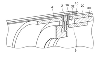
- FIG. 1 is a cross-sectional view of a main part of a zoom lens device when a variable magnification operation is performed.
- FIG. 2 is a cross-sectional view of a main part when the zoom lens device is subjected to a variable magnification operation.
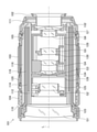
- FIG. 3 is a perspective view of a main part that moves when the zoom lens device is subjected to a variable magnification operation.
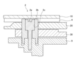
- FIG. 4 is a perspective sectional view showing the second cam follower pin 2.
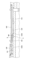
- FIG. 5 is a diagram showing a second straight groove provided in the fixed cylinder and a second cam follower pin that engages with the second straight groove.
- FIG. 6 is a perspective sectional view showing a second cam follower pin and a third cam follower pin.
- FIG. 7 is a perspective sectional view showing a second cam follower pin.
- FIG. 8 is a diagram illustrating one specific example of the second cam follower pin.
- FIG. 9 is a cross-sectional view showing a schematic configuration of an interchangeable lens.
- FIG. 10 is a diagram showing a configuration of a zoom lock mechanism.
- FIG. 11 is a developed view of the lock ring cam cylinder.
- FIG. 12 is a cross-sectional view showing a state of the zoom lock mechanism when the zoom lock is released.
- FIG. 13 is a cross-sectional view showing a state of the zoom lock mechanism when the zoom lock is performed.
- FIG. 14 is a diagram showing the position of the lock ring when the zoom lock is released.
- FIG. 15 is a diagram showing the operation of the lock ring when zoom locking is performed.
- FIG. 16 is a diagram showing the position of the lock ring at the time of zoom lock.
- the rotation regulation of the first lens group and the first moving group including the moving cylinder that moves integrally with the first lens group is often performed by the cam follower pin provided on the moving cylinder and the straight groove of the fixed cylinder.
- the cam follower pin formed on the moving cylinder engages with the cam groove of the cam cylinder in order to give a driving force to the first moving group, and is fixed to regulate the rotation of the first moving group. It is engaged with the straight groove of the cylinder.
- the rotation regulation of the first moving group is restricted to the straight groove formed in the moving cylinder which is a part of the first moving group and the second movement different from the first moving group. Perform with cam follower pins formed in groups. The present embodiment will be described below.
- 1 and 2 are cross-sectional views of a main part when the zoom lens device is subjected to a variable magnification operation.
- FIG. 1 is a cross-sectional view of the zoom lens device 1 in the telephoto end state
- FIG. 2 is a cross-sectional view of the zoom lens device 1 in the wide-angle end state
- FIG. 3 is a perspective view of a moving cylinder, a cam cylinder, and a fixed cylinder when performing a scaling operation of the zoom lens device 1.
- 1 to 3 show the optical axis L of the lens group of the zoom lens device 1.
- FIGS. 1 to 3 in the zoom lens device 1, a portion directly related to the present embodiment is described, and other portions are omitted. For example, in FIGS. 1 and 2, the aperture and the like are omitted.
- the zoom lens device 1 includes a moving cylinder 10, a cam cylinder 20, and a fixed cylinder 30 from the outside.
- the moving cylinder 10 includes a first lens holding portion 7, a first lens group H1, a first cam follower pin 3, and a first straight groove 4.
- the moving cylinder 10, the first lens holding portion 7, the first lens group H1, the first cam follower pin 3, and the first straight groove 4 collectively move the first moving group in the direction along the optical axis L.
- the moving cylinder 10 is located outside the cam cylinder 20 and includes a first lens holding portion 7 on the tip side, which is the subject side.
- the first lens holding unit 7 holds the first lens group H1.
- the moving cylinder 10 has a first cam follower pin 3 on the rear end side.
- the first cam follower pin 3 protrudes from the inner peripheral surface of the moving cylinder 10 and engages with the first cam groove 22 (see FIG. 3) of the cam cylinder 20.
- the rotation of the first moving group is restricted by engaging the first cam follower pin 3 with the straight groove formed in the fixed cylinder 30.
- the first cam follower pin 3 of the present embodiment engages only with the first cam groove 22 of the cam cylinder 20, and does not form a straight groove for the first moving group in the fixed cylinder 30.
- the moving cylinder 10 is formed with a first straight groove 4 for the first moving group that does not penetrate the inner peripheral surface.
- the first straight groove 4 is formed so as to extend in a direction along the optical axis L in a linear shape connecting the base end portion side and the tip end portion side of the moving cylinder 10.
- the first straight groove 4 has a concave shape, for example, and engages with the convex second cam follower pin 2.
- the first cam follower pin 3 and the first straight groove 4 may be formed at least one in the circumferential direction of the moving cylinder 10, and preferably three at equal intervals in the circumferential direction. Further, the number of the second cam follower pins 2 is the same as the number of the first straight grooves 4.
- the moving cylinder 10 moves in the direction along the optical axis L by rotating the cam cylinder 20 around the optical axis L.
- the first cam follower pin 3 formed on the moving cylinder 10 is engaged with the first cam groove 22 (FIG. 3) of the cam cylinder 20, and the cam cylinder 20 rotates. 1
- the cam follower pin 3 is driven, and the moving cylinder 10 moves in the front-rear direction along the optical axis L.
- a rotating force is applied by driving the first cam follower pin 3.
- the first straight groove 4 is engaged with the second cam follower pin 2
- the rotation of the moving cylinder 10 is restricted and the moving cylinder 10 is guided straight.
- the cam cylinder 20 has at least a first cam groove 22, a second cam groove 24, and a third cam groove 26 (see FIG. 3, and the third cam groove 26 is not shown in FIG. 3).
- the first cam groove 22 engages with the first cam follower pin 3 formed in the moving cylinder 10.
- the second cam groove 24 engages with the fixed cam follower pin 6 (fourth cam follower pin) formed in the fixed cylinder 30.
- the third cam groove 26 engages with the second cam follower pin 2 formed in the base frame 9.
- the cam cylinder 20 rotates about the optical axis L.
- the first cam follower pin 3 engaged with the first cam groove 22 is guided in the direction along the optical axis L and in the circumferential direction.
- the cam cylinder 20 moves in the direction along the optical axis L with respect to the fixed cylinder 30 due to the action of the engaged fixed cam follower pin 6 and the second cam groove 24. Guided in the circumferential direction.
- the fixed cylinder 30 includes a base frame 9, a focus unit 5, a base end lens holding portion 11, and a fixed cam follower pin 6.
- the base frame 9 includes a second lens holding portion 9A, a third lens holding portion 9B, and a second cam follower pin 2.
- the base frame 9, the second lens holding portion 9A, the third lens holding portion 9B, and the second cam follower pin 2 form a second moving group.
- the second lens holding portion 9A holds the second lens group H2, and the third lens holding portion 9B holds the third lens group H3.
- a second cam follower pin 2 that engages with the first straight groove 4 is formed on the tip end side of the base frame 9.
- the focus unit 5 includes a focus lens group, and adjusts the focus of the subject image by moving the focus lens group along the optical axis L.
- the detailed description of the focus unit 5 will be omitted.
- the base end lens holding portion 11 includes a base end lens group H4. Further, the base end side of the fixing cylinder 30 is fixed by the base member 40.
- a mount (not shown) is integrally attached to the base member 40, and is attached to the main body (optical device).
- the zoom lens device 1 can be attached to various optical devices.
- examples of the optical device to which the zoom lens device 1 is attached include binoculars, a microscope, an interchangeable lens camera, or a camera with an integrated lens.
- the fixed cam follower pin 6 is formed so as to project from the fixed cylinder 30, and is engaged with the second cam groove 24 formed in the cam cylinder 20.
- the cam cylinder 20 moves back and forth along the optical axis L with respect to the fixed cylinder 30.
- FIG. 4 is a perspective sectional view showing the second cam follower pin 2 of the present embodiment.
- FIG. 5 is a diagram showing a second cam follower pin 2 that engages with the second straight groove 32 and the second straight groove 32 provided in the fixed cylinder 30.
- the second cam follower pin 2 of the present embodiment penetrates the fixed cylinder 30 and the cam cylinder 20. Specifically, the second cam follower pin 2 engages with and penetrates the second straight groove 32 for the second moving group provided in the fixed cylinder 30, and the third cam groove 26 provided in the cam cylinder 20. Engaged and pierced. Then, the second cam follower pin 2 that penetrates the cam cylinder 20 engages with the first straight groove 4 formed in the moving cylinder 10.
- the second cam follower pin 2 engages with the first straight groove 4, regulates the rotation of the moving cylinder 10, and guides the moving cylinder 10 to go straight along the optical axis L.
- the cam cylinder 20 is engaged. By rotating around the optical axis L, it is driven along the optical axis L. As a result, the second moving group including the base frame 9 moves along the optical axis L.
- the moving cylinder 10 included in the first moving group is formed with a first straight groove 4 for performing straight-ahead guidance of the first moving group.
- the second cam follower pin 2 formed on the base frame 9 included in the second moving group penetrates the fixed cylinder 30 and the cam cylinder 20 and engages with the first straight groove 4. Therefore, the rotation of the moving cylinder 10 is restricted by the first straight groove 4 and the second cam follower pin 2. This makes it possible to increase the moving distance of the moving cylinder 10 in the direction along the optical axis L regardless of the length of the fixed cylinder 30. Further, according to the present embodiment, it is not necessary to further add a cam cylinder or the like in order to form a long straight groove, and the number of component parts of the zoom lens device 1 can be suppressed to a small number.
- the second cam follower pin 2 engages with the first straight groove 4, and the second cam groove 32 formed in the fixed cylinder 30 and the third cam groove 26 formed in the cam cylinder 20. Is also engaged. Therefore, the second cam follower pin 2 is driven in the direction along the optical axis L of the second moving group while guiding the moving cylinder 10 in a straight line. As a result, the number of components of the zoom lens device 1 can be reduced compared to forming a cam follower pin that engages with the first straight groove 4 and a cam follower pin that engages with the third cam groove 26 and the second straight groove 32. Can be done.
- the second cam follower pin 2 is made to guide the moving cylinder 10 in a straight line as in the first embodiment.
- the third cam follower pin 8 is further formed, and the third cam follower pin 8 guides the second moving group in a straight line.
- FIG. 6 is a perspective sectional view showing a second cam follower pin 2 and a third cam follower pin 8.
- the first cam groove 22 with which the first cam follower pin 3 is engaged is omitted.
- FIG. 7 is a perspective sectional view showing the second cam follower pin 2. In FIG. 7, the second lens holding portion 9A is omitted.
- the second cam follower pin 2 and the third cam follower pin 8 are formed on the base frame 9.
- the second cam follower pin 2 engages with the first straight groove 4 formed in the moving cylinder 10 via the fixed cylinder 30 and the cam cylinder 20. Specifically, the second cam follower pin 2 penetrates the fixed cylinder 30 and the cam cylinder 20 and engages with the first straight groove 4 without contacting and engaging with the fixed cylinder 30 and the cam cylinder 20. Further, in the case shown in FIG. 6, three second cam follower pins 2 are provided at equal intervals in the circumferential direction.
- the third cam follower pin 8 is formed on the base frame 9.
- the third cam follower pin 8 is engaged with the second straight groove 32 formed in the fixed cylinder 30. Further, the third cam follower pin 8 penetrates the fixed cylinder 30 and engages with the third cam groove 26 formed in the cam cylinder 20.
- the cam cylinder 20 rotates about the optical axis L, so that the third cam follower pin 8 is driven in the circumferential direction and the direction along the optical axis L, and the second moving group moves.
- three third cam follower pins 8 may be provided at equal intervals in the circumferential direction.
- the moving cylinder 10 included in the first moving group is formed with the first straight groove 4 for guiding the straight movement of the first moving group.
- the second cam follower pin 2 formed on the base frame 9 included in the second moving group is engaged with the first straight groove 4 via the fixed cylinder 30 and the cam cylinder 20. Therefore, the rotation of the moving cylinder 10 is restricted by the first straight groove 4 and the second cam follower pin 2. This makes it possible to increase the moving distance of the moving cylinder 10 in the direction along the optical axis L regardless of the length of the fixed cylinder 30.
- the movement of the second moving group in the direction along the optical axis L is performed by driving the third cam follower pin 8 which is separate from the second cam follower pin 2.
- the function for movement in the scaling operation can be divided into the second cam follower pin 2 and the third cam follower pin 8, respectively.
- FIG. 8 is a diagram illustrating one specific example of the second cam follower pin 2.
- the second cam follower pin 2 is composed of a screw 2a and a pin shaft portion 2b.
- the pin shaft portion 2b has a hollow cylindrical shape and has a hollow portion 2c along the shaft.
- the hollow portion 2c functions as an insertion portion for the screw 2a when the screw 2a is attached to the base frame 9.
- the upper portion of the pin shaft portion 2b abuts on the first straight groove 4 of the moving cylinder 10, and when the moving cylinder 10 moves, it slides on the first straight groove 4. Therefore, the pin shaft portion 2b is made of a material slidable with respect to the first straight groove 4.
- the second cam follower pin 2 regulates the rotation of the moving cylinder 10 by sliding the first straight groove 4. As a result, the second cam follower pin 2 guides the first moving group including the moving cylinder 10 in a straight line.
- the angle of the cam groove has become steeper due to the miniaturization of the lens barrel diameter. Further, in order to design a large amount of extension of the first moving group located closest to the subject, it is necessary to design the cam groove to have a steep angle. If the angle of the cam groove becomes steep in this way, the lens barrel will easily fall due to its own weight.
- the self-weight drop means that an unintended scaling operation occurs due to the weight of the zoom lens device itself.
- the technology disclosed below was made in view of these circumstances, and its purpose is to lock the zoom lens device at an arbitrary magnification and prevent the weight from falling by its own weight. And to provide an optical device.
- the locking mechanism of the zoom lens device is A lock ring that is provided adjacent to the zoom ring that rotates the cam cylinder of the zoom lens device and that moves in the optical axis direction by being rotated.
- a linear motion ring that engages with the lock ring and moves only in the optical axis direction as the lock ring moves in the optical axis direction.
- the lock mechanism according to the second aspect is preferably made of rubber in the first aspect.
- the lock mechanism according to the third aspect is the first aspect or the second aspect, and the first aspect stopper is a plate shape.
- the lock mechanism according to the fourth aspect is in any one of the first to third aspects, and the stopper abuts on the shoulder-shaped contact portion of the zoom ring or the rotating member.
- the locking mechanism according to the fifth aspect is the lock mechanism according to any one of the first to fourth aspects.
- the lock ring has a cam groove to which the fixed pin engages and has a cam tube to engage with the linear motion ring.
- the cam cylinder rotates in conjunction with the lock ring and moves together with the lock ring in the optical axis direction.
- the linear motion ring moves with the movement of the cam cylinder.
- the zoom lens device according to the sixth aspect includes the locking mechanism of the zoom lens device according to any one of the first to fifth aspects.
- the optical device according to the seventh aspect includes the zoom lens device according to the sixth aspect.
- the optical device includes, for example, binoculars, a microscope, an interchangeable lens camera, or a camera with an integrated lens.
- FIG. 9 is a cross-sectional view showing a schematic configuration of the interchangeable lens of the present embodiment.
- the interchangeable lens 101 (corresponding to the zoom lens device 1 described above) shown in the figure is an interchangeable lens for a digital still camera equipped with a focus mechanism, a zoom mechanism, and an optical image stabilization mechanism (Optical Image Stabilizer, OIS). ..
- the interchangeable lens 101 is detachably attached to a camera body (not shown) via a mount 102 provided at a base end portion.
- the lens barrel 110 of the interchangeable lens 101 of the present embodiment includes a first fixed cylinder 112, a cam cylinder 114, a moving cylinder 116, and a second fixed cylinder 118 in this order from the inside.
- the first fixed cylinder 112 and the second fixed cylinder 118 are members fixed to the mount 102. Both the first fixed cylinder 112 and the second fixed cylinder 118 are fixed to the base member 111 on the base end side (image side).
- the mount 102 is integrally attached to the base member 111.
- the cam cylinder 114 is a member that rotates in the circumferential direction around the first fixed cylinder 112.
- the cam cylinder 114 is rotated by the rotation operation of the zoom ring 103. That is, the cam cylinder 114 is manually rotated.
- the zoom ring 103 is provided on the outside of the second fixed cylinder 118 and is connected to the cam cylinder 114 via a connecting member (not shown).
- a lock ring 120, a focus ring 104, an aperture ring 105, and the like are provided on the outside of the second fixed cylinder 118.
- the zoom lock mechanism including the lock ring 120 will be described later.
- the moving cylinder 116 is a member that moves the inner peripheral portion of the second fixed cylinder 118 along the optical axis L. By rotating the cam cylinder 114, the moving cylinder 116 moves back and forth along the optical axis L by a cam mechanism (not shown).
- the 5 lens group G5, the 6th lens group G6, and the 7th lens group G7 are provided.
- a diaphragm is provided between the second lens group G2 and the third lens group G3.
- Each lens group is composed of at least one lens.
- the first lens group G1 to the sixth lens group G6 are lens groups that move during zooming.
- the seventh lens group G7 is a fixed lens group at the time of zooming.
- the first lens group G1 is held by the first lens group holding frame 123.
- the first lens group holding frame 123 is fixed and held to the tip of the moving cylinder 116. Therefore, the first lens group holding frame 123 moves by moving the moving cylinder 116.
- the second lens group G2 is a lens group that constitutes a blur correction lens.
- the second lens group G2 is held by the movable frame 125.
- the movable frame 125 is movably held with respect to the base frame 126 in a plane orthogonal to the optical axis L.
- the base frame 126 is movably held inside the first fixed cylinder 112 along the optical axis L. By rotating the cam cylinder 114, the base frame 126 moves back and forth along the optical axis L by a cam mechanism (not shown).
- the third lens group G3 to the sixth lens group G6 are held by the moving lens frame 128.
- the moving lens frame 128 is movably held inside the first fixed cylinder 112 along the optical axis L.
- the moving lens frame 128 moves back and forth along the optical axis L by a cam mechanism (not shown) by rotating the cam cylinder 114.
- the third lens group G3, the fourth lens group G4, and the sixth lens group G6 are fixed and held by the moving lens frame 128.
- the fifth lens group G5 is movably held with respect to the moving lens frame 128 along the optical axis L.
- the fifth lens group G5 is a lens group constituting a focus lens, and the focus is adjusted by moving the fifth lens group G5 back and forth along the optical axis L.
- the fifth lens group G5 is held by the focus lens frame 130 and is movably supported along the optical axis L. Further, the fifth lens group G5 is driven by an actuator provided in the moving lens frame 128 to move.
- the 7th lens group G7 is held by the 7th lens group holding frame 132.
- the seventh lens group holding frame 132 is fixed and held at the base end portion of the first fixed cylinder 112.
- the diaphragm unit 134 including the drive mechanism is integrally attached to the tip portion of the moving lens frame 128, and is arranged at a predetermined position.
- the main configuration of the zoom lock mechanism is composed of a lock ring 120, a lock ring cam cylinder 120A, a linear motion ring 122, a sliding ring 124, and a zoom ring 103.
- the lock ring cam cylinder 120A may be a part of the lock ring 120
- the sliding ring 124 may be a part of the zoom ring 103. That is, the lock ring cam cylinder 120A and the lock ring 120 may be integrated, or the sliding ring 124 and the zoom ring 103 may be integrated.
- the zoom lock mechanism is provided between the focus ring 104 and the aperture ring 105. In the zoom lock mechanism, the lock ring 120 (see FIG. 9) is rotated and moved back and forth along the optical axis L to switch between zoom lock and zoom lock release.
- FIG. 10 is a diagram showing a configuration of a zoom lock mechanism provided between the focus ring 104 and the aperture ring 105 of the lens barrel 110 described with reference to FIG.
- the lock ring 120 and the zoom ring 103 which are operation systems, are not shown in order to show the internal configuration.
- the lock ring cam cylinder 120A is provided inside the lock ring 120 (not shown in FIG. 10).
- the lock ring cam cylinder 120A is provided so as to be rotationally interlocked with the lock ring 120. Then, the lock ring cam cylinder 120A rotates about the optical axis L in conjunction with the lock ring 120 rotating about the optical axis L.
- a cam groove 121 is formed in the lock ring cam cylinder 120A, and the cam groove 121 engages with a cam follower pin 131 formed in the second fixed cylinder 118.
- FIG. 11 is a developed view of the lock ring cam cylinder 120A.
- the cam groove 121 of the lock ring cam cylinder 120A is such that when the lock ring cam cylinder 120A rotates about the optical axis L, the lock ring cam cylinder 120A moves in the direction (arrow 113) along the optical axis L. Is formed in.
- the cam groove 121 is composed of a groove center portion P1, a groove end portion P2, and a groove end portion P3.
- the groove center portion P1 is a groove for the lock ring cam cylinder 120A to move in the direction of the arrow 113, and is a straight groove inclined so as to move in the direction of the arrow 113 with the rotation of the lock ring cam cylinder 120A. ..
- the groove end portion P2 and the groove end portion P3 are grooves for fixing the position of the lock ring cam cylinder 120A when the zoom is locked or the zoom lock is released.
- the cam groove 121 of the lock ring cam cylinder 120A By forming the cam groove 121 of the lock ring cam cylinder 120A in this way, the zoom lock mechanism can be stably operated.
- one cam groove 121 is shown in FIG. 11, three cam grooves 121 may be arranged at equal intervals in the circumferential direction of the lock ring cam cylinder 120A.
- the linear motion ring 122 is engaged with the adjacent lock ring cam cylinder 120A in the direction along the optical axis L (see FIGS. 12 and 13). Further, the linear motion ring 122 has a linear groove 117. The straight groove 117 is engaged with the cam follower pin 119 fixed to the second fixed cylinder 118, whereby the rotation of the linear motion ring 122 around the optical axis L is restricted. Therefore, the linear motion ring 122 is restricted from rotating about the optical axis L, and moves back and forth in the same direction in conjunction with the movement of the lock ring cam cylinder 120A in the direction along the optical axis L. Further, a stopper S is fixed to the linear motion ring 122 (see FIG. 13).
- the stopper S is made of an elastic body and has a plate shape.
- the stopper S is a rubber plate-shaped member, and each set is provided at three positions in pairs at equal intervals in the circumferential direction of the linear motion ring 122.
- the number of stoppers S is not particularly limited, and may be a single number as long as the rotation of the sliding ring 124 can be restricted.
- the end of the stopper S has an assembly portion SA with the linear motion ring 122. Further, the end portion of the stopper S opposite to the assembly portion SA has a protrusion SB protruding from the end portion of the linear motion ring 122.
- the protrusion SB is in contact with the contact portion 124A of the sliding ring 124.
- the zoom lock and the zoom lock release are switched depending on the contact state between the protrusion SB and the contact portion 124A. The contact state between the assembly portion SA and the contact portion 124A in the zoom lock and the zoom lock release will be described later.
- the sliding ring 124 is provided inside the zoom ring 103 (not shown in FIG. 10).
- the sliding ring 124 is rotationally interlocked with the zoom ring 103 and is a rotating member of the zoom ring 103.
- the sliding ring 124 is connected to the cam cylinder 114 by a connecting member (not shown). Then, as the sliding ring 124 rotates about the optical axis L, the cam cylinder 114 also rotates and the scaling operation is performed.
- the zoom ring 103 and the sliding ring 124 are formed separately, but the zoom ring 103 and the sliding ring 124 may be integrally formed. That is, a contact portion 124A that comes into contact with the stopper S may be formed on a part of the zoom ring 103.
- FIG. 12 is a cross-sectional view showing a state of the zoom lock mechanism when the zoom lock is released.
- the lock ring 120 When the zoom lock is released, the lock ring 120 is located on the focus ring 104 side.
- the lock ring cam cylinder 120A that is rotationally interlocked with the lock ring 120 and the linear motion ring 122 that engages with the lock ring cam cylinder 120A in the L direction of the optical axis are also located on the focus ring 104 side.
- the protruding portion SB of the stopper S provided on the linear motion ring 122 abuts on the contact portion 124A of the sliding ring 124.
- the protruding portion SB is not crushed between the linear motion ring 122 and the sliding ring 124, but simply abuts on the contact portion 124A. Therefore, the protruding portion SB and the contact portion 124A slide. Therefore, the rotation of the sliding ring 124 in the circumferential direction is not restricted, and an arbitrary scaling operation can be performed by operating the zoom ring 103.
- Various shapes are adopted for the contact portion 124A of the sliding ring 124. For example, as shown in FIG. 12, the contact portion 124A is formed in a shoulder shape.
- the lock ring 120 is located on the focus ring 104 side when the zoom lock is released.
- the protruding portion SB of the stopper S is not crushed between the linear motion ring 122 and the sliding ring 124, but simply abuts on the abutting portion 124A, and is in contact with the abutting portion 124A in the circumferential direction of the sliding ring 124.
- the rotation to is not restricted, and the zoom ring 103 can be operated arbitrarily.
- FIG. 13 is a cross-sectional view showing a state of the zoom lock mechanism when the zoom lock is performed.
- the lock ring 120 is located on the zoom ring 103 side.
- the lock ring cam cylinder 120A that is rotationally interlocked with the lock ring 120 and the linear motion ring 122 that engages with the lock ring cam cylinder 120A in the L direction of the optical axis are also located on the zoom ring 103 side.
- the linear motion ring 122 and the sliding ring 124 are close to each other and the gap a disappears (becomes smaller).
- the protruding portion SB of the stopper S provided on the linear motion ring 122 abuts on the contact portion 124A of the sliding ring 124 and is crushed between the linear motion ring 122 and the sliding ring 124.
- the lock ring 120 is located on the zoom ring 103 side.
- the protruding portion SB of the stopper S is crushed between the linear motion ring 122 and the sliding ring 124, sliding with the contact portion 124A is restricted, and zoom lock is performed.
- this zoom lock mechanism is provided separately from the zoom mechanism that performs the scaling operation, the scaling operation is not performed by performing the zoom lock. Therefore, the user can perform zoom lock at the position (focal length) of any zoom ring 103. Specifically, the user can position the zoom ring 103 at an arbitrary position and operate the lock ring 120 to perform zoom lock.
- 14 to 16 are views for explaining the rotation operation of the lock ring 120, and are views showing the appearance of the lens barrel 110.
- FIG. 14 is a diagram showing the position of the lock ring 120 when the zoom lock is released
- FIG. 15 is a diagram showing the operation of the lock ring 120 when performing the zoom lock
- FIG. 16 is a diagram showing the operation of the lock ring 120 when the zoom lock is performed. It is a figure which shows the position of a ring 120.
- the lock ring 120 when the zoom lock is released, the lock ring 120 is located on the focus ring 104 side. Specifically, the lock ring 120 is located adjacent to the focus ring 104. Then, when the zoom lock is released, a gap a is provided between the lock ring 120 and the zoom ring 103.
- the lock ring 120 when zoom locking is performed, the lock ring 120 is rotated around the optical axis L as shown by the arrow shown in the figure.
- the rotation direction of the lock ring 120 and the forward / backward movement along the optical axis L are appropriately designed.
- the lock ring 120 moves in the direction along the optical axis L (the proximal end side of the lens barrel 110) as it rotates about the optical axis L.
- the lock ring 120 When the lock ring 120 is operated as described with reference to FIG. 15, the lock ring 120 is positioned adjacent to the zoom ring 103 at the time of zoom lock, as shown in FIG. In this way, by locating the lock ring 120 adjacent to the zoom ring 103, sliding between the protruding portion SB of the stopper S and the abutting portion 124A of the sliding ring 124 is restricted as described above. And zoom lock is performed.
- the rotation of the sliding ring 124 around the optical axis L is restricted by the protrusion SB of the stopper S, and the zoom lock is performed.
- the rotation of the sliding ring 124 can be restricted not only at the wide-angle end and the telephoto end but also at the position of the sliding ring 124.
- the scaling operation is not performed by performing the zoom lock.
Landscapes
- Physics & Mathematics (AREA)
- General Physics & Mathematics (AREA)
- Optics & Photonics (AREA)
- Engineering & Computer Science (AREA)
- General Engineering & Computer Science (AREA)
- Lens Barrels (AREA)
Abstract
最も被写体側にあるレンズ群を有する移動筒の光軸方向の移動距離を、部品点数を増やすことなく、長くすることができるズームレンズ装置及び光学装置を提供する。ズームレンズ装置(1)は、固定筒(30)と、固定筒(30)の外側に位置するカム筒(20)と、カム筒(20)の外側に位置し、先端部に第1レンズ群(H1)を有する第1移動群と、固定筒(30)の内側に位置し、第2レンズ群(H2)を有する第2移動群とを備える。第1移動群は、第1移動群を直進案内する第1直進溝(4)と、カム筒(20)に形成された第1カム溝と係合する第1カムフォロアピン(3)と、を備え、第2移動群は、固定筒(30)に形成された第2直進溝及びカム筒(20)に形成された第2カム溝を貫通し、第1直進溝(4)と係合する第2カムフォロアピン(2)と、を備える。
Description
本発明は、ズームレンズ装置及び光学装置に関する。
従来、ズームレンズ装置において、変倍動作で移動する移動群の移動に関する技術が提案されてきた。
特許文献1では、相対的に移動する固定筒と第1直進筒とにおいて、第1直進筒に別体で2つの突起部を形成し、固定筒にその2つの突起部とそれぞれ係合する2つの直進溝を形成し、固定筒と第1直進筒との係合する部分の長さを長くすることを目的としたズームレンズ装置が記載されている。
本開示の技術にかかる一の実施形態は、最も被写体側にあるレンズ群を有する移動筒の光軸方向の移動距離を、部品点数を増やすことなく、長くすることができるズームレンズ装置及び光学装置を提供することである。
本発明の一の態様であるズームレンズ装置は、固定筒と、固定筒の外側に位置するカム筒と、カム筒の外側に位置し、先端部に第1レンズ群を有する第1移動群と、固定筒の内側に位置し、第2レンズ群を有する第2移動群とを備え、カム筒の回転によって第1移動群及び第2移動群がそれぞれ移動して変倍動作するズームレンズ装置において、第1移動群は、第1移動群を直進案内する第1直進溝と、カム筒に形成された第1カム溝と係合する第1カムフォロアピンと、を備え、第2移動群は、固定筒に形成された第2直進溝及びカム筒に形成された第2カム溝を貫通し、第1直進溝と係合する第2カムフォロアピンと、を備える。
本発明の他の態様であるズームレンズ装置は、固定筒と、固定筒の外側に位置するカム筒と、カム筒の外側に位置し先端部に第1レンズ群を有する第1移動群と、固定筒の内側に位置し、第2レンズ群を有する第2移動群とを備え、カム筒の回転によって第1移動群及び第2移動群がそれぞれ移動して変倍動作するズームレンズ装置において、第1移動群は、第1移動群を直進案内する第1直進溝と、カム筒に形成された第1カム溝と係合する第1カムフォロアピンと、を備え、第2移動群は、固定筒及びカム筒を介して、第1移動群の第1直進溝と係合する第2カムフォロアピンと、固定筒に形成された第2直進溝及びカム筒に形成された第2カム溝に係合する第3カムフォロアピンと、を備える。
好ましくは、第1直進溝は、第1移動群の内周面に形成される。
好ましくは、第1移動群は、円周方向に1以上の第1直進溝を備える。
好ましくは、第1カムフォロアピンは、第1カム溝のみに係合する。
好ましくは、カム筒は、固定筒に設けられた第4カムフォロアピンと係合する第3カム溝を備え、カム筒は、回転によって、固定筒に対して光軸方向に移動する。
本発明の他の態様である光学装置は、上記のズームレンズ装置を有する。
<第1の実施形態>
以下、添付図面にしたがって本発明にかかるズームレンズ装置及び光学装置の好ましい実施の形態について説明する。
以下、添付図面にしたがって本発明にかかるズームレンズ装置及び光学装置の好ましい実施の形態について説明する。
先ず、従来の技術に関して説明を行う。
ズームレンズ装置の変倍動作が行われる際、最も被写体側にある第1レンズ群を含む第1移動群の光軸に沿った方向への移動を考える。第1レンズ群及び第1レンズ群と一体となり移動する移動筒を含む第1移動群の回転規制は、移動筒に設けられたカムフォロアピンと固定筒の直進溝とで行われることが多い。具体的には、移動筒に形成されるカムフォロアピンは、第1移動群に駆動力を与えるためにカム筒のカム溝に係合し、且つ、第1移動群の回転規制を行うために固定筒の直進溝に係合している。しかしながら、このように固定筒の直進溝により第1移動群の回転規制を行うと、第1移動群の移動量が大きい場合には、必要となる直進溝の長さが固定筒の長さからはみ出してしまい、第1移動群の回転規制が行えない。これを解決する技術として、もう一組のカム筒と直進溝を設ける技術もあるが、ズームレンズ装置の構成部品が多くなりコストアップする。また部品累積誤差が増えてしまうという問題がある。
そこで本実施形態では、これらを解決するために、第1移動群の回転規制を第1移動群の一部である移動筒に形成された直進溝と、第1移動群とは異なる第2移動群に形成したカムフォロアピンで行う。以下に本実施形態に関して説明を行う。
図1~図3に沿ってズームレンズ装置の構成について説明する。
図1及び図2は、ズームレンズ装置の変倍動作を行う場合の主要部の断面図である。
図1はズームレンズ装置1が望遠端状態の断面図であり、図2はズームレンズ装置1が広角端状態の断面図である。また、図3はズームレンズ装置1の変倍動作を行う際の移動筒、カム筒、及び固定筒の斜視図である。なお、図1~図3では、ズームレンズ装置1のレンズ群の光軸Lを示している。また、図1~図3では、ズームレンズ装置1において、本実施形態と直接関係する部分を記載し他の部分は省略されている。例えば、図1及び図2では、絞り等は省略されている。
ズームレンズ装置1は、外側より移動筒10、カム筒20、及び固定筒30を備える。
移動筒10は、第1レンズ保持部7、第1レンズ群H1、第1カムフォロアピン3、第1直進溝4を備える。ここで、移動筒10、第1レンズ保持部7、第1レンズ群H1、第1カムフォロアピン3、及び第1直進溝4は一体として光軸Lに沿った方向に移動する第1移動群を構成する。
移動筒10は、カム筒20の外側に位置し、被写体側である先端側に第1レンズ保持部7を備える。第1レンズ保持部7は第1レンズ群H1を保持する。移動筒10は、後端側に、第1カムフォロアピン3を有する。第1カムフォロアピン3は、移動筒10の内周面より突出しており、カム筒20の第1カム溝22(図3参照)に係合している。なお、前述したように、従来技術では第1カムフォロアピン3が固定筒30に形成される直進溝にも係合することにより、第1移動群の回転規制が行われていた。しかし、本実施形態の第1カムフォロアピン3は、カム筒20の第1カム溝22にのみに係合し、固定筒30に第1移動群用の直進溝を形成しない。
移動筒10には、内周面に不貫通の第1移動群用の第1直進溝4が形成されている。第1直進溝4は、光軸Lに沿った方向に、移動筒10の基端部側と先端部側と結ぶ直線形状に延びて形成されている。第1直進溝4は、例えば凹形状になっており、凸形状の第2カムフォロアピン2と係合する。移動筒10を含む第1移動群が移動する場合には、第2カムフォロアピン2は、第1直進溝4に当接し且つ摺動しながら、移動筒10は光軸Lに沿った方向に移動する。なお、第1カムフォロアピン3及び第1直進溝4は、移動筒10の円周方向に1つ以上あればよく、好ましくは円周方向に等間隔で3つ形成される。また、第2カムフォロアピン2は、第1直進溝4の形成される数と同数形成される。
移動筒10は、カム筒20が光軸Lを中心にして回転することにより、光軸Lに沿った方向に移動する。具体的には、移動筒10に形成されている第1カムフォロアピン3が、カム筒20の第1カム溝22(図3)と係合しており、カム筒20が回転することより、第1カムフォロアピン3が駆動され、移動筒10は光軸Lに沿って前後方向に移動する。ここで、移動筒10には、光軸Lに沿った方向に移動する場合には、第1カムフォロアピン3が駆動されることにより回転する力が作用される。しかし、第1直進溝4が第2カムフォロアピン2と係合していることにより、移動筒10は、回転が規制され直進案内される。
カム筒20は、少なくとも、第1カム溝22、第2カム溝24、第3カム溝26を有する(図3参照、なお図3では第3カム溝26は不図示)。第1カム溝22は、移動筒10に形成される第1カムフォロアピン3と係合する。第2カム溝24は、固定筒30に形成される固定カムフォロアピン6(第4カムフォロアピン)と係合する。第3カム溝26は、ベース枠9に形成される第2カムフォロアピン2と係合する。
カム筒20は光軸Lを中心として回転する。カム筒20が回転することにより、第1カム溝22と係合している第1カムフォロアピン3が光軸Lに沿った方向且つ円周方向に案内される。また、カム筒20が回転することにより、係合している固定カムフォロアピン6と第2カム溝24との作用により、カム筒20は、固定筒30に対して光軸Lに沿った方向且つ円周方向に案内される。
固定筒30は、ベース枠9、フォーカスユニット5、基端部レンズ保持部11、及び固定カムフォロアピン6を備える。ベース枠9は、第2レンズ保持部9A、第3レンズ保持部9B、及び第2カムフォロアピン2を備える。ベース枠9、第2レンズ保持部9A、第3レンズ保持部9B、及び第2カムフォロアピン2は、第2移動群を構成する。第2レンズ保持部9Aは第2レンズ群H2を保持し、第3レンズ保持部9Bは第3レンズ群H3を保持する。また、ベース枠9の先端側には、第1直進溝4と係合する第2カムフォロアピン2が形成されている。
フォーカスユニット5は、フォーカスレンズ群を備え、被写体像のフォーカスをフォーカスレンズ群を光軸Lに沿って移動させることにより調整する。なお、フォーカスユニット5の詳細な説明は省略する。
基端部レンズ保持部11は基端部レンズ群H4を備える。また、固定筒30の基端側はベース部材40により固定される。ベース部材40には、マウント(不図示)が一体的に取り付けられており、本体(光学装置)に取り付けられる。なお、ズームレンズ装置1は、様々な光学装置に取り付けることができる。例えば、ズームレンズ装置1が取り付けられる光学装置としては、例えば、双眼鏡、顕微鏡、レンズ交換式カメラ、またはレンズ一体型カメラが挙げられる。
固定カムフォロアピン6は、固定筒30から突出して形成されており、カム筒20に形成された第2カム溝24に係合される。カム筒20は光軸Lを中心にして回転することにより、固定筒30に対して光軸Lに沿って前後に移動する。
次に、図4及び図5に沿って、本実施形態の第2カムフォロアピン2に関して説明する。図4は、本実施形態の第2カムフォロアピン2を示す斜視断面図である。また、図5は、固定筒30に設けられる第2直進溝32と第2直進溝32に係合する第2カムフォロアピン2と示す図である。
本実施形態の第2カムフォロアピン2は、固定筒30、カム筒20を突き抜けている。具体的には、第2カムフォロアピン2は、固定筒30に設けられた第2移動群用の第2直進溝32と係合し且つ突き抜けて、カム筒20に設けられる第3カム溝26と係合し且つ突き抜けている。そして、カム筒20を突き抜けた第2カムフォロアピン2は、移動筒10に形成された第1直進溝4と係合する。
第2カムフォロアピン2は、第1直進溝4に係合し、移動筒10の回転規制を行い、移動筒10に対しての光軸Lに沿っての直進案内を行う。
また、第2カムフォロアピン2は、カム筒20に形成された第3カム溝26に係合し、固定筒30に形成された第2直進溝32と係合しているので、カム筒20が光軸Lを中心に回転することにより、光軸Lに沿って駆動される。これにより、ベース枠9を含む第2移動群は、光軸Lに沿って移動する。
以上で説明したように、本実施形態では、第1移動群に含まれる移動筒10に、第1移動群の直進案内を行うための第1直進溝4を形成している。そして、第2移動群に含まれるベース枠9に形成された第2カムフォロアピン2は、固定筒30及びカム筒20を貫通して、第1直進溝4に係合している。したがって、第1直進溝4と第2カムフォロアピン2とにより移動筒10の回転規制が行われる。これにより、固定筒30の長さにかかわらず、移動筒10の光軸Lに沿った方向の移動距離を長くすることができる。また、本実施形態によれば、直進溝を長く形成するためにカム筒を更に加える等を行う必要がなく、ズームレンズ装置1の構成部品の数を少なく抑えることができる。
更に、本実施形態では、第2カムフォロアピン2は、第1直進溝4に係合する共に、固定筒30に形成された第2直進溝32及びカム筒20に形成された第3カム溝26にも係合されている。したがって、第2カムフォロアピン2は、移動筒10の直進案内を行うと供に、第2移動群の光軸Lに沿った方向へ駆動されている。これにより、第1直進溝4に係合するカムフォロアピンと第3カム溝26及び第2直進溝32に係合するカムフォロアピンとを形成するよりも、ズームレンズ装置1の構成部品の数を少なく抑えることができる。
<第2の実施形態>
次に、第2の実施形態に関して説明する。本実施形態では、第1の実施形態と同様に第2カムフォロアピン2に移動筒10の直進案内を行わせる。そして、本実施形態では更に、第3カムフォロアピン8を形成し、第3カムフォロアピン8が第2移動群の直進案内を行わせる。
次に、第2の実施形態に関して説明する。本実施形態では、第1の実施形態と同様に第2カムフォロアピン2に移動筒10の直進案内を行わせる。そして、本実施形態では更に、第3カムフォロアピン8を形成し、第3カムフォロアピン8が第2移動群の直進案内を行わせる。
図6及び図7に沿って、本実施形態の第2カムフォロアピン2及び第3カムフォロアピン8に関して説明する。図6は、第2カムフォロアピン2及び第3カムフォロアピン8を示す斜視断面図である。なお、図6では第1カムフォロアピン3が係合する第1カム溝22は省略されている。図7は、第2カムフォロアピン2を示す斜視断面図である。なお、図7では、第2レンズ保持部9Aが省略されている。
ベース枠9には、第2カムフォロアピン2及び第3カムフォロアピン8が形成されている。
第2カムフォロアピン2は、固定筒30及びカム筒20を介して、移動筒10に形成された第1直進溝4に係合する。具体的には、第2カムフォロアピン2は、固定筒30及びカム筒20には当接及び係合せずに、固定筒30及びカム筒20を突き抜け、第1直進溝4に係合する。また、図6に示した場合では、第2カムフォロアピン2は、円周方向に等間隔で3つ設けられている。
また、本実施形態では、ベース枠9に第3カムフォロアピン8が形成されている。第3カムフォロアピン8は固定筒30に形成された第2直進溝32に係合している。また、第3カムフォロアピン8は、固定筒30を突き抜けてカム筒20に形成された第3カム溝26に係合している。これにより、カム筒20が光軸Lを中心にして回転することにより、第3カムフォロアピン8は円周方向及び光軸Lに沿った方向に駆動され、第2移動群が移動する。なお、第3カムフォロアピン8は、第2カムフォロアピン2と同様に円周方向に等間隔で3つ設けられてもよい。
以上で説明したように、本実施形態では、第1移動群に含まれる移動筒10に第1移動群の直進案内を行うための第1直進溝4を形成している。そして、第2移動群に含まれるベース枠9に形成された第2カムフォロアピン2は、固定筒30及びカム筒20を介して、第1直進溝4に係合している。したがって、第1直進溝4と第2カムフォロアピン2とにより移動筒10の回転規制が行われる。これにより、固定筒30の長さにかかわらず、移動筒10の光軸Lに沿った方向の移動距離を長くすることができる。また、本実施形態によれば、直進溝を長く形成するためにカム筒、直進筒を更に加える等を行う必要がなく、ズームレンズ装置1の構成部品の数を少なく抑えることができる。
更に、本実施形態では、第2移動群の光軸Lに沿った方向への移動は、第2カムフォロアピン2とは別体の第3カムフォロアピン8が駆動されることにより行われる。これにより、第2カムフォロアピン2及び第3カムフォロアピン8にそれぞれ変倍動作における移動のための機能を分けることができる。
<カムフォロアピンの例>
次に、上述した第2カムフォロアピン2の具体例に関して説明する。上述した第2カムフォロアピン2は、第1直進溝4に係合し移動筒10を回転規制することができれば、様々な形態を採用することができる。以下では、第2カムフォロアピン2の具体例を図8に沿って説明する。
次に、上述した第2カムフォロアピン2の具体例に関して説明する。上述した第2カムフォロアピン2は、第1直進溝4に係合し移動筒10を回転規制することができれば、様々な形態を採用することができる。以下では、第2カムフォロアピン2の具体例を図8に沿って説明する。
図8は、第2カムフォロアピン2の一つの具体例に関して説明する図である。
第2カムフォロアピン2は、ネジ2a及びピン軸部2bで構成される。ピン軸部2bは、中空の円柱形状を有し、軸に沿って中空部2cを有する。中空部2cは、ネジ2aをベース枠9に取り付ける際に、ネジ2aの挿通部として機能する。ピン軸部2bの上部は、移動筒10の第1直進溝4に当接し、移動筒10が移動する場合には、第1直進溝4を摺動する。したがって、ピン軸部2bは、第1直進溝4に対して摺動可能な材料で生成される。第2カムフォロアピン2は、第1直進溝4を摺動することにより、移動筒10の回転規制を行う。これにより、第2カムフォロアピン2は、移動筒10を含む第1移動群の直進案内を行う。
<付記>
以上で説明を行ったズームレンズ装置1に関連して以下の付記を開示する。
以上で説明を行ったズームレンズ装置1に関連して以下の付記を開示する。
従来、ズームレンズ装置において、持ち運びの際の利便性の向上を意図して、WIDE端にレンズが移動している状態でズームリングの回転を規制してズームロックを行う技術が知られている。
近年、レンズ鏡筒径の小型化に伴いカム溝の角度が急になっている。また、最も被写体側に位置する第1移動群の繰り出し量を大きく設計しようとすると、カム溝の角度を急にする設計を行わなければならない。このようにカム溝の角度が急になると、自重落下しやすいレンズ鏡筒となってしまう。ここで自重落下とは、ズームレンズ装置の自体の重さにより意図しない変倍動作が起こってしまうことをいう。自重落下がしやすいレンズ鏡筒を使用した撮影では、撮影時のレンズ姿勢及びレンズ環境温度の影響により、撮影者が画角を決めた後にもかかわらず、画角が勝手に変わってしまうという問題が発生する。
以下で開示する技術はこのような事情に鑑みてなされたもので、その目的は、任意倍率でズームロックを行い、自重落下を防ぐことを目的としたズームレンズ装置のロック機構、ズームレンズ装置、及び光学装置を提供することである。
上記目的を達成するために、以下の態様(手段)を開示する。
第1態様であるズームレンズ装置のロック機構は、
ズームレンズ装置のカム筒を回転させるズームリングに隣接して設けられ、回転操作されることにより光軸方向に移動するロックリングと、
ロックリングと係合し、ロックリングの光軸方向の移動に伴って光軸方向のみに移動する直動リングと、
直動リングに固定され、ズームリングまたはズームリングとともに回転する回転部材に当接する弾性体からなるストッパと、を備え、
ロックリングがロック方向に回転操作されると、直動リングがズームリングの方向に移動し、ストッパがズームリングまたは回転部材に当接してズームリングを固定する。
ズームレンズ装置のカム筒を回転させるズームリングに隣接して設けられ、回転操作されることにより光軸方向に移動するロックリングと、
ロックリングと係合し、ロックリングの光軸方向の移動に伴って光軸方向のみに移動する直動リングと、
直動リングに固定され、ズームリングまたはズームリングとともに回転する回転部材に当接する弾性体からなるストッパと、を備え、
ロックリングがロック方向に回転操作されると、直動リングがズームリングの方向に移動し、ストッパがズームリングまたは回転部材に当接してズームリングを固定する。
第2態様であるロック機構は、第1態様において、好ましくは、ストッパは、ゴムで構成される。
第3態様であるロック機構は、第1態様または第2態様において、第1態様ストッパは、板形状である。
第4態様であるロック機構は、第1態様~第3態様のいずれか1態様にいて、ストッパは、ズームリングまたは回転部材の肩形状の当接部に当接する。
第5態様であるロック機構は、第1態様~第4態様のいずれか1態様において、
ロックリングは、固定されたピンが係合するカム溝を有し、直動リングと係合するカム筒を備え、
カム筒は、ロックリングと回転連動し、光軸方向にロックリングともに移動し、
直動リングは、カム筒の移動に伴って移動する。
ロックリングは、固定されたピンが係合するカム溝を有し、直動リングと係合するカム筒を備え、
カム筒は、ロックリングと回転連動し、光軸方向にロックリングともに移動し、
直動リングは、カム筒の移動に伴って移動する。
第6態様であるズームレンズ装置は、第1態様から第5態様のうちいずれか1つに記載のズームレンズ装置のロック機構を備える。
第7態様である光学装置は、第6態様のズームレンズ装置を備える。ここで光学装置とは、例えば、双眼鏡、顕微鏡、レンズ交換式カメラ、またはレンズ一体型カメラが挙げられる。
[レンズ鏡筒の全体構成]
ここでは、レンズ交換式カメラの交換レンズに本開示の技術を適用した場合を例に説明する。
ここでは、レンズ交換式カメラの交換レンズに本開示の技術を適用した場合を例に説明する。
図9は、本実施形態の交換レンズの概略構成を示す断面図である。
同図に示す交換レンズ101(上述したズームレンズ装置1に対応)は、フォーカス機構、ズーム機構及び光学式手ブレ補正機構(Optical Image Stabilizer,OIS)を備えたデジタルスチルカメラ用の交換レンズである。この交換レンズ101は、基端部に備えられたマウント102を介して、カメラ本体(不図示)に着脱自在に装着される。
図9に示すように、本実施形態の交換レンズ101のレンズ鏡筒110は、内側から順に第1固定筒112、カム筒114、移動筒116及び第2固定筒118を備える。
第1固定筒112及び第2固定筒118は、マウント102に対し、固定の部材である。第1固定筒112及び第2固定筒118は、共に基端部側(像側)においてベース部材111に固定される。ベース部材111には、マウント102が一体的に取り付けられる。
カム筒114は、第1固定筒112の周りを円周方向に回転する部材である。カム筒114は、ズームリング103の回転操作により回転する。すなわち、カム筒114は、手動で回転する。ズームリング103は、第2固定筒118の外側に備えられ、図示しない連結部材を介してカム筒114と連結される。なお、第2固定筒118の外側には、ズームリング103の他、ロックリング120、フォーカスリング104、絞りリング105等が備えられる。なお、ロックリング120を含めたズームロック機構の説明は後で行う。
移動筒116は、第2固定筒118の内周部を光軸Lに沿って移動する部材である。移動筒116は、カム筒114を回転させることにより、図示しないカム機構によって、光軸Lに沿って前後移動する。
レンズ鏡筒110の内部には、光軸Lに沿って物体側(図9の左側)から順に第1レンズ群G1、第2レンズ群G2、第3レンズ群G3、第4レンズ群G4、第5レンズ群G5、第6レンズ群G6及び第7レンズ群G7が備えられる。第2レンズ群G2と第3レンズ群G3との間には、絞りが備えられる。各レンズ群は、少なくとも1枚のレンズで構成される。第1レンズ群G1から第6レンズ群G6は、ズームの際に移動するレンズ群である。第7レンズ群G7は、ズームの際に固定のレンズ群である。
第1レンズ群G1は、第1レンズ群保持枠123に保持される。第1レンズ群保持枠123は、移動筒116の先端に固定されて保持される。したがって、第1レンズ群保持枠123は、移動筒116の移動により移動する。
第2レンズ群G2は、ブレ補正レンズを構成するレンズ群である。第2レンズ群G2は、可動枠125に保持される。可動枠125は、ベース枠126に対し、光軸Lと直交する面内で移動可能に保持される。ベース枠126は、第1固定筒112の内側を光軸Lに沿って移動可能に保持される。ベース枠126は、カム筒114を回転させることにより、図示しないカム機構によって、光軸Lに沿って前後移動する。
第3レンズ群G3から第6レンズ群G6は、移動レンズ枠128に保持される。移動レンズ枠128は、第1固定筒112の内側を光軸Lに沿って移動可能に保持される。移動レンズ枠128は、カム筒114を回転させることにより、図示しないカム機構によって、光軸Lに沿って前後移動する。
ここで、第3レンズ群G3、第4レンズ群G4及び第6レンズ群G6は、移動レンズ枠128に固定されて保持される。
一方、第5レンズ群G5は、移動レンズ枠128に対し、光軸Lに沿って移動可能に保持される。第5レンズ群G5は、フォーカスレンズを構成するレンズ群であり、この第5レンズ群G5を光軸Lに沿って前後移動させることにより、焦点調節が行われる。第5レンズ群G5は、フォーカスレンズ枠130に保持されて、光軸Lに沿って移動自在に支持される。また、第5レンズ群G5は、移動レンズ枠128に備えられたアクチュエータに駆動されて移動する。
第7レンズ群G7は、第7レンズ群保持枠132に保持される。第7レンズ群保持枠132は、第1固定筒112の基端部に固定されて保持される。
絞りは、その駆動機構を含む絞りユニット134が、移動レンズ枠128の先端部分に一体的に取り付けられて、所定位置に配置される。
[ズームロック機構の構成]
次に、ズームロック機構の構成に関して説明する。
次に、ズームロック機構の構成に関して説明する。
ズームロック機構の主な構成は、ロックリング120、ロックリングカム筒120A、直動リング122、摺動リング124、及びズームリング103で構成される。なお、ロックリングカム筒120Aはロックリング120の一部であり、摺動リング124はズームリング103の一部としてもよい。すなわち、ロックリングカム筒120Aとロックリング120とを一体としてもよく、摺動リング124とズームリング103とを一体としてもよい。ズームロック機構は、フォーカスリング104と絞りリング105との間に設けられる。ズームロック機構は、ロックリング120(図9参照)が回転操作され、光軸Lに沿って前後移動することにより、ズームロックまたはズームロック解除の切り替えが行われる。
図10は、図9で説明したレンズ鏡筒110のフォーカスリング104と絞りリング105との間に設けられるズームロック機構の構成を示す図である。なお、内部構成を示すため、操作系であるロックリング120及びズームリング103の図示は省略されている。
ロックリングカム筒120Aは、ロックリング120(図10では不図示)の内側に設けられる。ロックリングカム筒120Aは、ロックリング120と回転連動するように設けられている。そして、ロックリングカム筒120Aは、ロックリング120が光軸Lを中心にして回転するのと連動して、光軸Lを中心にして回転する。ロックリングカム筒120Aにはカム溝121が形成されており、カム溝121は第2固定筒118に形成されたカムフォロアピン131と係合する。
図11は、ロックリングカム筒120Aの展開図である。
ロックリングカム筒120Aのカム溝121は、ロックリングカム筒120Aが光軸Lを中心にして回転した場合に、ロックリングカム筒120Aが光軸Lに沿った方向(矢印113)に移動するように形成されている。カム溝121は、溝中心部P1、溝端部P2及び溝端部P3で構成される。溝中心部P1は、ロックリングカム筒120Aが矢印113の方向に移動するための溝であり、ロックリングカム筒120Aの回転に伴って矢印113の方向に移動するように傾斜したストレート溝である。溝端部P2及び溝端部P3は、ズームロック時またはズームロック解除時に、ロックリングカム筒120Aの位置固定を行うための溝である。このように、ロックリングカム筒120Aのカム溝121を形成することにより、ズームロック機構を安定して作動させることができる。なお、図11では、一つのカム溝121を示しているが、カム溝121はロックリングカム筒120Aの円周方向に等間隔3つ配置されてもよい。
直動リング122は、隣接するロックリングカム筒120Aと光軸Lに沿った方向で係合している(図12及び図13参照)。また直動リング122は、直進溝117を有する。直進溝117は第2固定筒118に固定されたカムフォロアピン119と係合しており、これにより直動リング122の光軸Lを中心とする回転への規制が行われる。したがって、直動リング122は、光軸Lを中心とした回転は規制され、ロックリングカム筒120Aの光軸Lに沿った方向への移動に連動して同じ方向へ前後移動する。また、直動リング122には、ストッパSが固定されている(図13参照)。ストッパSは、弾性体で構成され、板形状である。例えば、ストッパSは、ゴムの板状部材であり、2つ一組で3箇所に直動リング122の円周方向に各組が等間隔で設けられる。なお、ストッパSの個数は、特に限定されるものはでは無く、摺動リング124の回転規制を行えれば、単数でもよい。ストッパSの端部には直動リング122との組み付け部SAを有する。また、ストッパSの組み付け部SAと逆の端部には、直動リング122の端部から食み出ている食み出し部SBを有する。食み出し部SBは、摺動リング124の当接部124Aに当接される。食み出し部SBと当接部124Aとの当接状態により、ズームロックとズームロック解除の切り替えが行われる。なお、ズームロック及びズームロック解除における、組み付け部SAと当接部124Aとの当接状態の説明は後で行う。
摺動リング124は、ズームリング103(図10では不図示)の内側に設けられる。摺動リング124はズームリング103と回転連動し、ズームリング103の回転部材である。摺動リング124は、図示しない連結部材により、カム筒114と連結している。そして、摺動リング124が光軸Lを中心にして回転することにより、カム筒114も回転して変倍動作が行われる。なお、本例ではズームリング103と摺動リング124とは別体で形成されているが、ズームリング103と摺動リング124とは一体に形成されていてもよい。すなわち、ズームリング103の一部に、ストッパSと当接する当接部124Aが形成されていてもよい。
[ズームロック]
次に、図12及び図13に沿って、ズームロックが行われる際のズームロック機構の各部の動作に関して説明する。
次に、図12及び図13に沿って、ズームロックが行われる際のズームロック機構の各部の動作に関して説明する。
先ず図12に沿って、ズームロック解除の場合のズームロック機構の状態を説明する。図12は、ズームロック解除の場合のズームロック機構の状態を示す断面図である。
ズームロック解除の場合には、ロックリング120は、フォーカスリング104側に位置する。そして、ロックリング120と回転連動するロックリングカム筒120A、及びロックリングカム筒120Aと光軸L方向に係合する直動リング122もフォーカスリング104側に位置する。直動リング122と摺動リング124との間には隙間aを有する。直動リング122に備えられるストッパSの食み出し部SBは、摺動リング124の当接部124Aに当接する。この場合食み出し部SBは、直動リング122と摺動リング124との間で押し潰されず、単に当接部124Aに当接している。したがって、食み出し部SBと当接部124Aは摺動する。よって、摺動リング124の円周方向への回転は規制されず、ズームリング103を操作することにより任意の変倍動作を行うことができる。なお、摺動リング124の当接部124Aは、様々な形状が採用される。例えば、図12に示すように当接部124Aは肩形状で形成される。
以上で説明したように、ズームロック解除時には、ロックリング120がフォーカスリング104側に位置する。これにより、ストッパSの食み出し部SBは、直動リング122と摺動リング124との間で押し潰されず、単に当接部124Aに当接しており、摺動リング124の円周方向のへの回転は規制されず、ズームリング103を任意に操作を行うことができる。
次に、図13に沿って、ズームロックが行われる場合のズームロック機構の状態を説明する。図13は、ズームロックが行われる場合のズームロック機構の状態を示す断面図である。
ズームロックが行われている場合には、ロックリング120は、ズームリング103側に位置する。そして、ロックリング120と回転連動するロックリングカム筒120A、及びロックリングカム筒120Aと光軸L方向に係合する直動リング122もズームリング103側に位置する。この場合には、直動リング122と摺動リング124とは近接し隙間aは無くなる(小さくなる)。直動リング122に備えられるストッパSの食み出し部SBは、摺動リング124の当接部124Aに当接し、直動リング122と摺動リング124との間で押し潰される。これは、例えば図示しない固定ピンで、摺動リング124の光軸Lの方向への移動規制が行われており、光軸Lに沿って摺動リング124側に押される直動リング122と当接部124Aとの間で挟まれるからである。そして、食み出し部SBが押し潰されることにより、食み出し部SBと当接部124Aとの摺動が規制され、摺動リング124(ズームリング103)の回転の規制が行われる。これにより、摺動リング124(ズームリング103)を自在に回転しなくなり、ズームロックが行われる。
以上で説明したように、ズームロックが行われている場合には、ロックリング120がズームリング103側に位置する。これにより、ストッパSの食み出し部SBは、直動リング122と摺動リング124との間で押し潰され、当接部124Aとの摺動が規制され、ズームロックが行われる。なお、本ズームロック機構は、変倍動作を行うズーム機構とは別で設けられているので、ズームロックを行うことにより変倍動作は行われない。したがって、ユーザは、任意のズームリング103の位置(焦点距離)でズームロックを行うことができる。具体的には、ユーザは任意の位置にズームリング103を位置させ、ロックリング120を操作してズームロックを行うことができる。
[操作]
次に、ズームロック解除及びズームロックを行う場合のロックリング120の操作に関して説明する。
次に、ズームロック解除及びズームロックを行う場合のロックリング120の操作に関して説明する。
図14~図16は、ロックリング120の回転操作を説明する図であり、レンズ鏡筒110の外観を示す図である。
図14は、ズームロック解除時のロックリング120の位置を示す図であり、図15は、ズームロックを行う場合のロックリング120の操作を示す図であり、図16は、ズームロック時のロックリング120の位置を示す図である。
図14に示すように、ズームロック解除時には、ロックリング120はフォーカスリング104側に位置している。具体的には、ロックリング120はフォーカスリング104に隣接して位置する。そして、ズームロック解除時には、ロックリング120とズームリング103との間には隙間aが空けられる。
図15に示すように、ズームロックを行う場合には、ロックリング120は光軸Lを中心にして図示した矢印のように回転させる。なお、ロックリング120の回転方向と光軸Lに沿っての前後移動は、適宜設計される。ロックリング120は、光軸Lを中心にして回転するのに伴って、光軸Lに沿った方向(レンズ鏡筒110の基端側)に移動する。
図15で説明したようにロックリング120が操作されると、図16に示すように、ズームロック時には、ロックリング120は、ズームリング103と隣接して位置する。このように、ロックリング120がズームリング103と隣接して位置することにより、上述したようにストッパSの食み出し部SBと摺動リング124の当接部124Aとの間の摺動が規制され、ズームロックが行われる。
以上で説明したように、本ズームロック機構によれば、摺動リング124の光軸Lを中心とした回転がストッパSの食み出し部SBに規制され、ズームロックが行われる。これにより、本ズームロック機構を有するズームレンズ装置では、自重落下を抑制することができる。また、本ズームロック機構によれば、広角端や望遠端だけでなく、任意の摺動リング124の位置で、摺動リング124の回転規制を行うことができる。また、本ズームロック機構によれば、変倍動作を行うズーム機構とは別で設けられているので、ズームロックを行うことにより変倍動作は行われない。
以上で本発明の例に関して説明してきたが、本発明は上述した実施の形態に限定されず、本発明の趣旨を逸脱しない範囲で種々の変形が可能であることは言うまでもない。
1 :ズームレンズ装置
2 :第2カムフォロアピン
3 :第1カムフォロアピン
4 :第1直進溝
5 :フォーカスユニット
6 :固定カムフォロアピン
7 :第1レンズ保持部
8 :第3カムフォロアピン
9 :ベース枠
9A :第2レンズ保持部
9B :第3レンズ保持部
10 :移動筒
11 :基端部レンズ保持部
20 :カム筒
22 :第1カム溝
24 :第2カム溝
26 :第3カム溝
30 :固定筒
32 :第2直進溝
40 :ベース部材
2 :第2カムフォロアピン
3 :第1カムフォロアピン
4 :第1直進溝
5 :フォーカスユニット
6 :固定カムフォロアピン
7 :第1レンズ保持部
8 :第3カムフォロアピン
9 :ベース枠
9A :第2レンズ保持部
9B :第3レンズ保持部
10 :移動筒
11 :基端部レンズ保持部
20 :カム筒
22 :第1カム溝
24 :第2カム溝
26 :第3カム溝
30 :固定筒
32 :第2直進溝
40 :ベース部材
Claims (7)
- 固定筒と、前記固定筒の外側に位置するカム筒と、前記カム筒の外側に位置し、先端部に第1レンズ群を有する第1移動群と、前記固定筒の内側に位置し、第2レンズ群を有する第2移動群とを備え、前記カム筒の回転によって前記第1移動群および前記第2移動群がそれぞれ移動して変倍動作するズームレンズ装置において、
前記第1移動群は、
前記第1移動群を直進案内する第1直進溝と、
前記カム筒に形成された第1カム溝と係合する第1カムフォロアピンと、を備え、
前記第2移動群は、
前記固定筒に形成された第2直進溝および前記カム筒に形成された第2カム溝を貫通し、前記第1直進溝と係合する第2カムフォロアピンと、を備える、
ズームレンズ装置。 - 固定筒と、前記固定筒の外側に位置するカム筒と、前記カム筒の外側に位置し、先端部に第1レンズ群を有する第1移動群と、前記固定筒の内側に位置し、第2レンズ群を有する第2移動群とを備え、前記カム筒の回転によって前記第1移動群および前記第2移動群がそれぞれ移動して変倍動作するズームレンズ装置において、
前記第1移動群は、
前記第1移動群を直進案内する第1直進溝と、
前記カム筒に形成された第1カム溝と係合する第1カムフォロアピンと、を備え、
前記第2移動群は、
前記固定筒および前記カム筒を介して、前記第1移動群の前記第1直進溝と係合する第2カムフォロアピンと、
前記固定筒に形成された第2直進溝および前記カム筒に形成された第2カム溝に係合する第3カムフォロアピンと、
を備える、
ズームレンズ装置。 - 前記第1直進溝は、前記第1移動群の内周面に形成される請求項1又は2に記載のズームレンズ装置。
- 前記第1移動群は、円周方向に1以上の前記第1直進溝を備える請求項1から3のいずれか1項に記載のズームレンズ装置。
- 前記第1カムフォロアピンは、前記第1カム溝のみに係合する請求項1から4のいずれか1項に記載のズームレンズ装置。
- 前記カム筒は、前記固定筒に設けられた第4カムフォロアピンと係合する第3カム溝を備え、
前記カム筒は、回転によって、前記固定筒に対して光軸方向に移動する請求項1から5のいずれか1項に記載のズームレンズ装置。 - 前記請求項1から6のいずれか1項に記載のズームレンズ装置を有する光学装置。
Priority Applications (2)
| Application Number | Priority Date | Filing Date | Title |
|---|---|---|---|
| JP2022540267A JP7360553B2 (ja) | 2020-07-31 | 2021-07-26 | ズームレンズ装置及び光学装置 |
| US18/156,782 US20230152555A1 (en) | 2020-07-31 | 2023-01-19 | Zoom lens device and optical device |
Applications Claiming Priority (2)
| Application Number | Priority Date | Filing Date | Title |
|---|---|---|---|
| JP2020130635 | 2020-07-31 | ||
| JP2020-130635 | 2020-07-31 |
Related Child Applications (1)
| Application Number | Title | Priority Date | Filing Date |
|---|---|---|---|
| US18/156,782 Continuation US20230152555A1 (en) | 2020-07-31 | 2023-01-19 | Zoom lens device and optical device |
Publications (1)
| Publication Number | Publication Date |
|---|---|
| WO2022024954A1 true WO2022024954A1 (ja) | 2022-02-03 |
Family
ID=80035551
Family Applications (1)
| Application Number | Title | Priority Date | Filing Date |
|---|---|---|---|
| PCT/JP2021/027446 WO2022024954A1 (ja) | 2020-07-31 | 2021-07-26 | ズームレンズ装置及び光学装置 |
Country Status (3)
| Country | Link |
|---|---|
| US (1) | US20230152555A1 (ja) |
| JP (1) | JP7360553B2 (ja) |
| WO (1) | WO2022024954A1 (ja) |
Citations (5)
| Publication number | Priority date | Publication date | Assignee | Title |
|---|---|---|---|---|
| JPH04345112A (ja) * | 1991-05-23 | 1992-12-01 | Minolta Camera Co Ltd | レンズ鏡胴 |
| JPH08136791A (ja) * | 1994-11-04 | 1996-05-31 | Nikon Corp | ズームレンズ鏡筒 |
| JP2006284865A (ja) * | 2005-03-31 | 2006-10-19 | Fujinon Corp | レンズ鏡筒 |
| JP2007264220A (ja) * | 2006-03-28 | 2007-10-11 | Fujinon Corp | ズームレンズ装置 |
| US20160054539A1 (en) * | 2014-08-25 | 2016-02-25 | Olympus Corporation | Lens barrel |
Family Cites Families (1)
| Publication number | Priority date | Publication date | Assignee | Title |
|---|---|---|---|---|
| JP4345112B2 (ja) | 1998-08-24 | 2009-10-14 | 豊丸産業株式会社 | パチンコ機 |
-
2021
- 2021-07-26 WO PCT/JP2021/027446 patent/WO2022024954A1/ja active Application Filing
- 2021-07-26 JP JP2022540267A patent/JP7360553B2/ja active Active
-
2023
- 2023-01-19 US US18/156,782 patent/US20230152555A1/en active Pending
Patent Citations (5)
| Publication number | Priority date | Publication date | Assignee | Title |
|---|---|---|---|---|
| JPH04345112A (ja) * | 1991-05-23 | 1992-12-01 | Minolta Camera Co Ltd | レンズ鏡胴 |
| JPH08136791A (ja) * | 1994-11-04 | 1996-05-31 | Nikon Corp | ズームレンズ鏡筒 |
| JP2006284865A (ja) * | 2005-03-31 | 2006-10-19 | Fujinon Corp | レンズ鏡筒 |
| JP2007264220A (ja) * | 2006-03-28 | 2007-10-11 | Fujinon Corp | ズームレンズ装置 |
| US20160054539A1 (en) * | 2014-08-25 | 2016-02-25 | Olympus Corporation | Lens barrel |
Also Published As
| Publication number | Publication date |
|---|---|
| US20230152555A1 (en) | 2023-05-18 |
| JPWO2022024954A1 (ja) | 2022-02-03 |
| JP7360553B2 (ja) | 2023-10-12 |
Similar Documents
| Publication | Publication Date | Title |
|---|---|---|
| JP4969859B2 (ja) | レンズ鏡筒 | |
| JP6814954B2 (ja) | レンズ鏡筒 | |
| US8248709B2 (en) | Zoom lens barrel that attains a higher photographing magnification | |
| JP4964654B2 (ja) | レンズ鏡胴、カメラおよび情報機器 | |
| EP1795935B1 (en) | Lens barrel and method of operation of lens barrel | |
| US8305696B2 (en) | Inner focusing zoom lens | |
| US7515355B2 (en) | Compact zoom lens | |
| JP2022097724A (ja) | レンズ鏡筒および撮像装置 | |
| US9551855B2 (en) | Lens barrel and optical apparatus | |
| JP4899845B2 (ja) | レンズ鏡筒、レンズ鏡筒の操作方法およびカメラシステム | |
| CN107991750B (zh) | 抑制光学单元的不期望的运动的镜筒和摄像设备 | |
| JP6529220B2 (ja) | レンズ駆動装置、レンズ鏡筒および光学機器 | |
| WO2022024954A1 (ja) | ズームレンズ装置及び光学装置 | |
| JP2006234962A (ja) | レンズ鏡筒 | |
| JP5475554B2 (ja) | レンズ鏡筒 | |
| JP4487531B2 (ja) | レンズ鏡筒 | |
| JP2008209647A (ja) | レンズ調芯機構、鏡筒及び撮像装置 | |
| JP2018022008A (ja) | レンズ鏡筒及び撮像装置 | |
| JP2011237546A (ja) | レンズ鏡筒 | |
| US6839187B2 (en) | Lens distance-varying mechanism, and step-zoom lens incorporating the same | |
| JP4479293B2 (ja) | レンズ鏡筒 | |
| JP2001235672A (ja) | レンズ装置 | |
| JPH1020173A (ja) | カメラのズームレンズ鏡筒 | |
| WO2010021150A1 (ja) | レンズ鏡筒および撮像装置 | |
| JP4557707B2 (ja) | レンズ装置 |
Legal Events
| Date | Code | Title | Description |
|---|---|---|---|
| 121 | Ep: the epo has been informed by wipo that ep was designated in this application |
Ref document number: 21849074 Country of ref document: EP Kind code of ref document: A1 |
|
| ENP | Entry into the national phase |
Ref document number: 2022540267 Country of ref document: JP Kind code of ref document: A |
|
| NENP | Non-entry into the national phase |
Ref country code: DE |
|
| 122 | Ep: pct application non-entry in european phase |
Ref document number: 21849074 Country of ref document: EP Kind code of ref document: A1 |