WO2022024261A1 - 空気調和装置 - Google Patents
空気調和装置 Download PDFInfo
- Publication number
- WO2022024261A1 WO2022024261A1 PCT/JP2020/029060 JP2020029060W WO2022024261A1 WO 2022024261 A1 WO2022024261 A1 WO 2022024261A1 JP 2020029060 W JP2020029060 W JP 2020029060W WO 2022024261 A1 WO2022024261 A1 WO 2022024261A1
- Authority
- WO
- WIPO (PCT)
- Prior art keywords
- air
- temperature
- air volume
- indoor
- angle
- Prior art date
- Legal status (The legal status is an assumption and is not a legal conclusion. Google has not performed a legal analysis and makes no representation as to the accuracy of the status listed.)
- Ceased
Links
Images


Classifications
-
- F—MECHANICAL ENGINEERING; LIGHTING; HEATING; WEAPONS; BLASTING
- F24—HEATING; RANGES; VENTILATING
- F24F—AIR-CONDITIONING; AIR-HUMIDIFICATION; VENTILATION; USE OF AIR CURRENTS FOR SCREENING
- F24F11/00—Control or safety arrangements
- F24F11/70—Control systems characterised by their outputs; Constructional details thereof
- F24F11/72—Control systems characterised by their outputs; Constructional details thereof for controlling the supply of treated air, e.g. its pressure
- F24F11/74—Control systems characterised by their outputs; Constructional details thereof for controlling the supply of treated air, e.g. its pressure for controlling air flow rate or air velocity
-
- F—MECHANICAL ENGINEERING; LIGHTING; HEATING; WEAPONS; BLASTING
- F24—HEATING; RANGES; VENTILATING
- F24F—AIR-CONDITIONING; AIR-HUMIDIFICATION; VENTILATION; USE OF AIR CURRENTS FOR SCREENING
- F24F11/00—Control or safety arrangements
- F24F11/70—Control systems characterised by their outputs; Constructional details thereof
- F24F11/72—Control systems characterised by their outputs; Constructional details thereof for controlling the supply of treated air, e.g. its pressure
- F24F11/79—Control systems characterised by their outputs; Constructional details thereof for controlling the supply of treated air, e.g. its pressure for controlling the direction of the supplied air
-
- Y—GENERAL TAGGING OF NEW TECHNOLOGICAL DEVELOPMENTS; GENERAL TAGGING OF CROSS-SECTIONAL TECHNOLOGIES SPANNING OVER SEVERAL SECTIONS OF THE IPC; TECHNICAL SUBJECTS COVERED BY FORMER USPC CROSS-REFERENCE ART COLLECTIONS [XRACs] AND DIGESTS
- Y02—TECHNOLOGIES OR APPLICATIONS FOR MITIGATION OR ADAPTATION AGAINST CLIMATE CHANGE
- Y02B—CLIMATE CHANGE MITIGATION TECHNOLOGIES RELATED TO BUILDINGS, e.g. HOUSING, HOUSE APPLIANCES OR RELATED END-USER APPLICATIONS
- Y02B30/00—Energy efficient heating, ventilation or air conditioning [HVAC]
- Y02B30/70—Efficient control or regulation technologies, e.g. for control of refrigerant flow, motor or heating
Definitions
- This disclosure relates to an air conditioner that regulates the temperature of a space such as a living space.
- Patent Document 1 discloses an air conditioner that raises the room temperature to a certain temperature or higher by performing convection heating with the wind direction diagonally downward and the maximum amount of air blown when the heating operation is started.
- the purpose of the conventional air conditioner is to quickly air-condition the air in the air-conditioned space and all the heat loads including the frame such as the wall and floor at the time of starting.
- the required air conditioning capacity becomes large, which leads to an increase in power consumption.
- the present disclosure is for solving the above-mentioned problems, and an object of the present disclosure is to provide an air conditioner capable of improving efficiency while maintaining comfort at startup.
- the air conditioner according to the present disclosure includes a heat exchanger that exchanges heat between air and a refrigerant, a fan that blows air heated or cooled by the heat exchanger into the air-conditioned space, and air blown into the air-conditioned space. It is equipped with a wind direction plate that changes the angle of the air conditioner and a control device that controls the air volume of the fan and the angle of the wind direction plate. Set the angle to be larger than the degree, set the angle of the wind direction plate to an angle smaller than 45 degrees when the vertical direction is 0 degree at the start of heating, and set the air volume of the fan to the maximum air volume at the start of cooling and the start of heating. It is set to a smaller start-up air volume.
- the air conditioner of the present disclosure it is possible to preferentially cool or heat the air in the air-conditioned space at the time of starting, and it is possible to improve the efficiency while maintaining the comfort at the time of starting. ..
- FIG. It is a schematic block diagram of the air conditioner which concerns on Embodiment 1.
- FIG. It is a control block diagram of the air conditioner which concerns on Embodiment 1.
- FIG. It is a figure which shows the operation at the time of the cooling operation of the indoor unit which concerns on Embodiment 1.
- FIG. It is a psychrometric chart which shows the state change of the air at the time of the cooling operation of the indoor unit which concerns on Embodiment 1.
- FIG. It is a figure which shows the operation at the time of the heating operation of the indoor unit which concerns on Embodiment 1.
- FIG. It is a psychrometric chart which shows the state change of the air at the time of the heating operation of the indoor unit which concerns on Embodiment 1.
- FIG. It is a figure which shows the heat load to the conventional house at the time of cooling. It is a figure which shows the heat load to a house in recent years at the time of cooling. It is a figure which shows the change of the air volume of an indoor fan in the conventional cooling start-up operation. It is a figure which shows the change of the air volume of the room fan in the cooling start operation which concerns on Embodiment 1.
- FIG. It is a figure which shows the change of the room air temperature and the wall temperature by the conventional cooling start operation. It is a figure which shows the change of the room air temperature and the wall temperature by the cooling start operation which concerns on Embodiment 1.
- FIG. It is a figure which shows the change of the power consumption of the air conditioner by the conventional cooling start operation.
- FIG. It is a figure which shows the change of the power consumption of the air conditioner by the cooling start operation which concerns on Embodiment 1.
- FIG. It is a figure which shows the influence of the wind direction and the air volume by the conventional cooling start operation. It is a figure which shows the influence of the wind direction and the air volume by the cooling start operation which concerns on Embodiment 1.
- FIG. It is a flowchart of the cooling start operation of the air conditioner which concerns on Embodiment 1.
- FIG. It is a figure which shows the heat load to the conventional house at the time of heating. It is a figure which shows the heat load to the house in recent years at the time of heating. It is a figure which shows the change of the room air temperature and the wall temperature by the conventional heating start-up operation.
- FIG. It is a figure which shows the change of the room air temperature and the wall temperature by the heating start operation which concerns on Embodiment 1.
- FIG. It is a figure which shows the influence of the wind direction and the air volume by the heating start operation which concerns on Embodiment 1.
- FIG. It is a flowchart of the heating start operation of the air conditioner which concerns on Embodiment 1.
- FIG. It is a control block diagram of the air conditioner which concerns on Embodiment 2.
- FIG. It is a flowchart of the cooling start operation of the air conditioner which concerns on Embodiment 3.
- FIG. It is a flowchart of the heating start operation of the air conditioner which concerns on Embodiment 3.
- FIG. It is a figure which shows the influence which the wind speed has on the floor surface temperature in the conventional cooling start-up operation.
- FIG. It is a figure which shows the influence which the wind speed has on the floor surface temperature in the cooling start operation which concerns on Embodiment 4.
- FIG. It is a figure which shows the influence which the wind speed has on the floor surface temperature in the conventional heating start-up operation. It is a figure which shows the influence which the wind speed has on the floor surface temperature in the heating start operation which concerns on Embodiment 4.
- FIG. It is a control block diagram of the air conditioner which concerns on Embodiment 5.
- FIG. 1 is a schematic configuration diagram of an air conditioner 100 according to the first embodiment.
- the air conditioner 100 of the first embodiment includes an outdoor unit 1 arranged outside the air-conditioned space and an indoor unit 2 arranged inside the air-conditioned space.
- the outdoor unit 1 and the indoor unit 2 are connected by wiring such as piping, a power supply, or a signal line.
- the outdoor unit 1 includes a compressor 11, a flow path switching valve 12, an outdoor heat exchanger 13, an expansion valve 14, and an outdoor fan 15.
- the indoor unit 2 includes an indoor heat exchanger 21, an indoor fan 22, a wind direction plate 23, a first temperature sensor 31, a second temperature sensor 32, an indoor temperature sensor 33, a wall temperature sensor 34, and a control device. It is equipped with 5.
- the compressor 11, the flow path switching valve 12, the outdoor heat exchanger 13, the expansion valve 14, and the indoor heat exchanger 21 are connected by pipes to form a refrigerant circuit.
- the refrigerant circulating in the refrigerant circuit of the air conditioner 100 is, for example, a natural refrigerant such as carbon dioxide, hydrocarbon or helium, a chlorine-free refrigerant such as HFC410A or HFC407C, or a fluorocarbon-based refrigerant such as R22 or R134a.
- the compressor 11 is a fluid machine that sucks in a low-pressure gas refrigerant, compresses it, and discharges it as a high-pressure gas refrigerant.
- various types of compressors such as reciprocating engines, rotary engines, scrolls, and screws are used.
- the operating frequency of the compressor 11 is controlled by the control device 5.
- the flow path switching valve 12 is a four-way valve that switches between a cooling operation in which the outdoor heat exchanger 13 functions as a condenser and a heating operation in which the outdoor heat exchanger 13 functions as an evaporator.
- the flow path switching valve 12 is switched so that the refrigerant discharged from the compressor 11 flows into the outdoor heat exchanger 13 during the cooling operation, as shown by the solid line in FIG.
- the flow path switching valve 12 is switched so that the refrigerant discharged from the compressor 11 flows into the indoor heat exchanger 21 during the heating operation, as shown by the broken line in FIG.
- the outdoor heat exchanger 13 is, for example, a plate fin tube type heat exchanger that exchanges heat between the refrigerant flowing inside the circular tube or the flat tube and the air supplied by the outdoor fan 15.
- the outdoor heat exchanger 13 is arranged between the flow path switching valve 12 and the expansion valve 14.
- the outdoor heat exchanger 13 functions as an evaporator during the heating operation and as a condenser during the cooling operation.
- the expansion valve 14 is a valve that reduces the pressure of the refrigerant.
- the expansion valve 14 is an electronic expansion valve whose opening degree can be adjusted by the control device 5.
- the expansion valve 14 is arranged between the outdoor heat exchanger 13 and the indoor heat exchanger 21. Although the expansion valve 14 is arranged in the outdoor unit 1 in FIG. 1, it may be arranged in the indoor unit 2.
- the outdoor fan 15 sucks in the air outside the air-conditioned space, passes it through the outdoor heat exchanger 13, and blows it out of the air-conditioned space.
- the outdoor fan 15 is, for example, a propeller fan, a sirocco fan, or a cross-flow fan driven by a motor.
- the air volume of the outdoor fan 15 is controlled by controlling the rotation speed of the outdoor fan 15 by the control device 5.
- the control device 5 controls the air volume of the outdoor fan 15 by controlling the rotation speed by changing the current value.
- the control device 5 controls the air volume of the outdoor fan 15 by controlling the rotation speed by changing the power supply frequency by inverter control.
- the indoor heat exchanger 21 is, for example, a plate fin tube type heat exchanger, and exchanges heat between the refrigerant circulating inside the circular tube or the flat tube and the air blown by the indoor fan 22.
- the indoor heat exchanger 21 is arranged between the expansion valve 14 and the flow path switching valve 12.
- the indoor heat exchanger 21 functions as a condenser during the heating operation and as an evaporator during the cooling operation.
- the indoor fan 22 sucks in the air in the air-conditioned space, passes it through the indoor heat exchanger 21, and blows it out into the air-conditioned space.
- the indoor fan 22 is, for example, a propeller fan, a sirocco fan, or a cross-flow fan driven by a motor.
- the air volume of the indoor fan 22 is controlled by controlling the rotation speed of the indoor fan 22 by the control device 5.
- the control device 5 controls the air volume of the indoor fan 22 by controlling the rotation speed by changing the current value.
- the control device 5 controls the air volume of the indoor fan 22 by controlling the rotation speed by changing the power supply frequency by inverter control.
- one indoor fan 22 is arranged upstream of the indoor heat exchanger 21 in the air flow, but if the target air volume can be obtained, the arrangement and number of the indoor fans 22 are shown in FIG. It is not limited to the example of 1.
- the indoor fan 22 may be arranged downstream of the indoor heat exchanger 21, or a plurality of indoor fans 22 may be arranged upstream and downstream of the indoor heat exchanger 21, respectively.
- the indoor unit 2 is a wall-mounted indoor unit that can be attached to the wall of the air-conditioned space.
- the housing of the indoor unit 2 is provided with a suction port 20a and an outlet 20b.
- the air in the air-conditioned space is sucked by the indoor fan 22 from the suction port 20a, cooled or heated by the indoor heat exchanger 21, and blown out to the air-conditioned space from the air outlet 20b.
- the wind direction plate 23 is rotatably provided on a rotation axis parallel to the horizontal direction at the outlet 20b, and adjusts the blowing direction of the conditioned air cooled or heated by the indoor heat exchanger 21 in the vertical direction.
- the angle of the wind direction plate 23 is an angle when the vertical direction is 0 degrees when the indoor unit 2 is installed on the wall of the air-conditioned space.
- the first temperature sensor 31 is provided in the pipe connecting the indoor heat exchanger 21 and the expansion valve 14, and detects the temperature of the refrigerant on the inlet side of the indoor heat exchanger 21 during the cooling operation.
- the second temperature sensor 32 is provided in the pipe connecting the indoor heat exchanger 21 and the flow path switching valve 12, and detects the temperature of the refrigerant on the outlet side of the indoor heat exchanger 21 during the cooling operation. The refrigerant temperature detected by the first temperature sensor 31 and the second temperature sensor 32 is transmitted to the control device 5.
- the indoor temperature sensor 33 is arranged around the suction port 20a and detects the temperature of the air sucked into the indoor unit 2 from the air-conditioned space.
- the indoor air temperature Ta detected by the indoor temperature sensor 33 is transmitted to the control device 5.
- the wall temperature sensor 34 is provided in the housing of the indoor unit 2 and detects the temperature of the wall in the air-conditioned space. Specifically, the wall temperature sensor 34 detects the temperature of the wall facing the indoor unit 2 and located in the direction of blowing out the conditioned air of the indoor unit 2.
- the wall temperature sensor 34 is, for example, an infrared sensor such as a thermopile sensor that can measure the temperature of an object in a non-contact manner.
- the wall temperature Tw detected by the wall temperature sensor 34 is transmitted to the control device 5.
- the control device 5 is a microcomputer equipped with a CPU, ROM, RAM, an I / O port, and the like.
- the control device 5 adjusts the air based on the instruction from the user input via the remote control or the like and the detection results of the first temperature sensor 31, the second temperature sensor 32, the indoor temperature sensor 33, and the wall temperature sensor 34. It controls the operation of the entire device 100.
- the control device 5 is provided in the indoor unit 2 in FIG. 1, it may be provided in the outdoor unit 1, or the outdoor unit 1 and the indoor unit 2 are provided with individual control devices 5 to communicate with each other. It may be configured to be used.
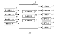
- FIG. 2 is a control block diagram of the air conditioner 100 according to the first embodiment.
- the control device 5 of the air conditioner 100 has an operation control unit 51, an air volume control unit 52, and a wind direction control unit 53 as functional units.
- Each functional unit is realized by the control device 5 executing a program, or is realized by a dedicated processing circuit.
- the operation control unit 51 performs cooling operation and heating based on the setting information input via the remote control or the like and the detection results of the first temperature sensor 31, the second temperature sensor 32, the room temperature sensor 33, and the wall temperature sensor 34. Perform driving.
- the input setting information is, for example, a cooling operation, a heating operation setting, and a set temperature Tn.
- the operation control unit 51 controls the operation frequency of the compressor 11, the switching of the flow path switching valve 12, the opening degree of the expansion valve 14, and the rotation speed of the outdoor fan 15 based on the setting information and the detection result of each temperature sensor. ..
- the air volume control unit 52 controls the air volume of the indoor fan 22 based on the setting information input via the remote controller or the like and the temperature detected by the indoor temperature sensor 33 and the wall temperature sensor 34.
- the wind direction control unit 53 controls the angle of the wind direction plate 23 based on the setting information input via the remote controller or the like.
- the operation of the air conditioner 100 during the cooling operation will be described.
- the refrigerant compressed by the compressor 11 and turned into a high-temperature and high-pressure gas flows into the outdoor heat exchanger 13 that functions as a condenser.
- the refrigerant undergoes a phase change from a high-temperature, high-pressure gas to a liquid in the outdoor heat exchanger 13, and heats the air passing through the outdoor heat exchanger 13.
- the refrigerant is depressurized by the expansion valve 14 set to have a small opening degree, becomes a two-phase state in which a low-temperature low-pressure liquid and a gas are mixed, and flows into the indoor heat exchanger 21 functioning as an evaporator.
- the refrigerant phase changes from a liquid to a gas and cools the air passing through the indoor heat exchanger 21. After that, the refrigerant flows into the compressor 11 and becomes a high-temperature and high-pressure gas again.
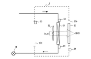
- FIG. 3 is a diagram showing the operation of the indoor unit 2 according to the first embodiment during the cooling operation.
- the control device 5 sets the opening degree of the expansion valve 14 to be small.
- the pressure of the refrigerant flowing into the indoor heat exchanger 21 decreases.
- the degree of superheat calculated from the difference between the inlet temperature of the refrigerant detected by the first temperature sensor 31 and the outlet temperature of the refrigerant detected by the second temperature sensor 32 becomes a predetermined value.
- the opening degree of the expansion valve 14 is controlled.
- the air (A1) in the air-conditioned space is supplied by the indoor fan 22 to the indoor heat exchanger 21 that functions as an evaporator.
- the indoor heat exchanger 21 cools the passing air.
- the cooled conditioned air (B1) is supplied into the conditioned space.
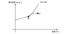
- FIG. 4 is a psychrometric chart showing a change in the state of air during the cooling operation of the indoor unit 2 according to the first embodiment.
- the horizontal axis of FIG. 4 represents temperature (° C.), and the vertical axis represents absolute humidity (kg / kg').
- Points A1 and B1 in FIG. 4 correspond to the positions (A1) and (B1) in FIG. 3, respectively.
- the air (A1) that has passed through the indoor heat exchanger 21 is cooled and dehumidified by heat exchange with the refrigerant, and is in a low temperature and high relative humidity state, and then in a state in which the absolute humidity is lowered (A). It becomes B1) and is supplied as air supply to the air-conditioned space.
- Heating operation The operation of the air conditioner 100 during the heating operation will be described.
- the refrigerant compressed by the compressor 11 and turned into a high-temperature and high-pressure gas flows into the indoor heat exchanger 21 that functions as a condenser.
- the refrigerant undergoes a phase change from a high-temperature, high-pressure gas to a liquid in the indoor heat exchanger 21, and heats the air passing through the indoor heat exchanger 21.
- the refrigerant is depressurized by the expansion valve 14 whose opening degree is set small, becomes a two-phase state in which a low-temperature low-pressure liquid and a gas are mixed, and flows into the outdoor heat exchanger 13 functioning as an evaporator.
- the refrigerant changes phase from a liquid to a gas and cools the air passing through the outdoor heat exchanger 13.
- the refrigerant flows into the compressor 11 and becomes a high-temperature and high-pressure gas again.
- FIG. 5 is a diagram showing the operation of the indoor unit 2 according to the first embodiment during the heating operation.
- the control device 5 sets the opening degree of the expansion valve 14 to be small. As a result, the pressure of the refrigerant flowing into the outdoor heat exchanger 13 decreases. Further, the control device 5 opens the expansion valve 14 so that the supercooling degree calculated from the difference between the outlet temperature of the refrigerant detected by the second temperature sensor 32 and the condensation temperature of the refrigerant becomes a predetermined value. Control the degree.
- the air (A2) in the air-conditioned object is supplied to the indoor heat exchanger 21 functioning as a condenser by the indoor fan 22.
- the indoor heat exchanger 21 heats the passing air. After that, the heated conditioned air (B2) is supplied to the conditioned space.
- FIG. 6 is a psychrometric chart showing a change in the air state during the heating operation of the indoor unit 2 according to the first embodiment.
- the horizontal axis of FIG. 6 represents temperature (° C.), and the vertical axis represents absolute humidity (kg / kg').
- Points A2 and B2 in FIG. 6 correspond to the positions (A2) and (B2) in FIG. 5, respectively.
- the air (A2) that has passed through the indoor heat exchanger 21 is heated by heat exchange with the refrigerant, becomes a high temperature state (B2), and is supplied to the air-conditioned space as supply air.
- the cooling start-up operation in the present embodiment will be described.
- the air volume and direction of the air-conditioned air are controlled so as to realize a highly efficient and high-capacity operating state for the air-conditioned space and to reach the set temperature at an early stage. ..
- the air volume of the room fan 22 is set to be larger than that when the room temperature is stable, and the wind direction of the conditioned air is the center of the room or 45. It was set every time.
- FIG. 7 is a diagram showing a heat load on a conventional house during cooling
- FIG. 8 is a diagram showing a heat load on a recent house during cooling.
- the arrows in FIGS. 7 and 8 indicate the heat load, and the size of the arrow indicates the magnitude of the heat load.
- the heat load related to the house includes a once-through heat load La generated from a temperature difference from the outside, a ventilation load Lb due to draft, a heat load Lc due to mechanical ventilation, and solar radiation.
- the once-through heat load La is reduced as compared with the conventional case.
- the ventilation load Lb is reduced as compared with the conventional case. That is, in recent years, as the heat load during cooling, the heat load Lc due to mechanical ventilation and the heat load Ld due to solar radiation are the main factors, and the heat load La and the ventilation load Lb, which are heat loads from the wall surface, are greatly reduced. is doing.
- the room temperature was reached to the target temperature by increasing the air volume and cooling the air-conditioned space including the skeleton such as the wall and the floor.
- the heat load from the wall surface is smaller than before, and the heat load does not change significantly even if the difference between the outside air temperature and the room temperature becomes large. Therefore, in the air conditioner 100 of the present embodiment, at the time of starting the cooling operation, the cooling start operation of giving priority to the air temperature of the air-conditioned space is performed.
- FIG. 9 is a diagram showing changes in the air volume of the indoor fan in the conventional cooling start operation.
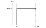
- FIG. 10 is a diagram showing changes in the air volume of the indoor fan 22 in the cooling start-up operation according to the first embodiment.
- the horizontal axis of FIGS. 9 and 10 shows time, and the vertical axis shows the air volume of the indoor fan 22.
- the "cooling start operation” is defined as an operation from the start of the cooling operation to the time when the indoor air temperature Ta reaches the set temperature Tn.
- the air volume of the indoor fan is set to the maximum air volume at t0 at the start of the cooling operation, and the air volume of the indoor fan is reduced at the time tun when the set temperature Tn is reached. ..
- the air volume control unit 52 sets the air volume of the indoor fan 22 to the start air volume at t0 at the start of the cooling operation.
- the start-up air volume is an air volume set to lower only the temperature of the air in the air-conditioned space, and is set so that the air blown out from the outlet 20b does not directly hit the wall or the floor.
- the air volume at startup is equal to or greater than the air volume according to the lower limit of the rotation speed of the motor of the indoor fan 22, and is smaller than the maximum air volume of the indoor fan 22.
- the start-up air volume is, for example, an air volume at which the reach of the air blown from the outlet 20b is equal to or less than the distance to the wall surface facing the indoor unit 2.
- the reachable distance is, for example, the distance from the outlet 20b to a place where the velocity of the blown air is 0.25 m / s.
- the starting air volume is set to 80% of the maximum air volume.
- the start-up air volume may be a constant value regardless of the difference between the start-up indoor air temperature Ta and the set temperature Tn, or may be a constant value depending on the difference between the start-up indoor air temperature Ta and the set temperature Tn. Different air volumes may be set. However, in any case, the air volume at startup is set to be smaller than the maximum air volume of the indoor fan 22.
- the reach of the air blown out from the outlet 20b can be shortened, and the air temperature in the air-conditioned space can be selectively lowered. ..
- the skeleton such as the wall and the floor in order to lower the indoor air temperature Ta to the set temperature Tn, so that the required air conditioning capacity can be reduced.
- the air volume control unit 52 increases the air volume of the indoor fan 22 when the indoor air temperature Ta detected by the indoor temperature sensor 33 approaches the set temperature Tn.
- the efficiency of the refrigeration cycle of the air conditioner 100 can be improved, and the comfort and comfort can be improved. Energy saving is improved.
- the air volume control unit 52 sets the air volume of the indoor fan 22 to the maximum air volume when the time tun is reached, that is, when the indoor air temperature Ta detected by the indoor temperature sensor 33 reaches the set temperature Tn.
- the air volume control unit 52 sets the air volume of the indoor fan 22 as the maximum air volume until the wall temperature Tw detected by the wall temperature sensor 34 becomes equal to the indoor air temperature Ta.
- the entire space including the skeleton of the air-conditioned space is cooled.
- the influence of radiant heat from the skeleton is reduced and the comfort is improved.
- FIG. 11 is a diagram showing changes in the indoor air temperature Ta and the wall temperature Tw due to the conventional cooling start operation.
- FIG. 12 is a diagram showing changes in the indoor air temperature Ta and the wall temperature Tw due to the cooling start-up operation according to the first embodiment.
- the horizontal axis of FIGS. 11 and 12 indicates time, and the vertical axis indicates temperature.
- the air in the air-conditioned space and the skeleton are targeted for cooling, so that the indoor air temperature Ta and the wall temperature Tw are similarly lowered.
- the indoor air temperature Ta first drops to the set temperature Tn, and then the wall temperature. Tw goes down.
- FIG. 13 is a diagram showing changes in the power consumption of the air conditioner due to the conventional cooling start operation.
- FIG. 14 is a diagram showing a change in power consumption of the air conditioner 100 due to the cooling start operation according to the first embodiment.
- the horizontal axis of FIGS. 13 and 14 shows time, and the vertical axis shows the power consumption of the air conditioner 100.
- the air volume of the indoor fan 22 is set to the start air volume smaller than the maximum air volume, so that the set temperature Tn is reached from t0 at the start of the cooling operation.
- the power consumption up to the time tun can be made lower than that of the conventional example.
- the air volume of the indoor fan 22 at the start of the cooling operation is reduced by the control of the air volume control unit 52, so that the wind speed of the air blown out from the outlet 20b is lowered. Therefore, at the time of the cooling start operation of the present embodiment, the influence of the vertical movement of the conditioned air due to the density difference becomes larger than that at the time of the conventional cooling start operation.
- the temperature of the air blown out from the outlet 20b during the cooling operation is lower than the air temperature of the air-conditioned space. Therefore, the density of the air blown out from the outlet 20b during the cooling operation becomes higher than that of the surroundings, and the wind direction changes in the downward direction.
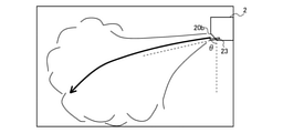
- the wind direction control unit 53 sets the angle ⁇ of the wind direction plate 23 so that the blowing direction of the conditioned air becomes larger than 45 degrees when the vertical direction is 0 degree in the cooling start operation. Specifically, the angle ⁇ of the wind direction plate 23 is set to be larger than 45 degrees when the vertical direction is 0 degrees.
- the wind direction control unit 53 may set the angle ⁇ of the wind direction plate 23 to any angle between 45 degrees and 90 degrees (horizontal direction). As a result, the cold air does not cool the ceiling surface, and the conditioned air can be efficiently diffused into the conditioned space. Further, as the angle ⁇ of the wind direction plate 23 is set to be larger than 45 degrees, the air volume at the time of starting the indoor fan 22 is set to be large, so that cold air can be efficiently supplied to the air-conditioned space.
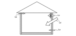
- FIG. 15 is a diagram showing the influence of the wind direction and the air volume due to the conventional cooling start operation.
- FIG. 16 is a diagram showing the effects of the wind direction and the air volume due to the cooling start-up operation according to the first embodiment.
- 15 and 16 are views of the air-conditioned space in which the indoor unit 2 is installed, as viewed from the side.
- the air volume of the indoor fan becomes the maximum air volume, so that the air blown out from the air outlet directly hits the wall and the floor, and the entire air-conditioned space including the skeleton is covered. It will be cooled.
- FIG. 15 is a diagram showing the influence of the wind direction and the air volume due to the conventional cooling start operation.
- FIG. 16 is a diagram showing the effects of the wind direction and the air volume due to the cooling start-up operation according to the first embodiment.
- 15 and 16 are views of the air-conditioned space in which the indoor unit 2 is installed, as viewed from the side.
- the air volume of the indoor fan becomes the maximum air volume, so that the air
- the air volume of the indoor fan 22 is set to be smaller than the maximum air volume, and the angle ⁇ of the wind direction plate 23 is set to be larger than 45 degrees.
- the air blown out from the outlet 20b is circulated in the air-conditioned space without hitting the wall, and the air in the air-conditioned space can be preferentially cooled.
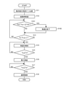
- FIG. 17 is a flowchart of the cooling start operation of the air conditioner 100 according to the first embodiment.
- the flowchart of FIG. 17 is executed by the control device 5 when the start of the cooling operation is instructed.
- the angle ⁇ of the wind direction plate 23 is set to be larger than 45 degrees by the wind direction control unit 53 (S11).
- the air volume of the indoor fan 22 is set to the air volume at startup by the air volume control unit 52 (S12).
- the air volume at startup is smaller than the maximum air volume of the indoor fan 22.
- the air volume control unit 52 determines whether or not the indoor air temperature Ta detected by the indoor temperature sensor 33 has approached the set temperature Tn. Specifically, it is determined whether or not the difference between the indoor air temperature Ta and the set temperature Tn is equal to or less than the threshold value ⁇ (S13).
- ⁇ is a preset threshold value, for example, 2 ° C.
- the cooling operation at the start-up air volume is continued.
- the difference between the indoor air temperature Ta and the set temperature Tn is equal to or less than the threshold value ⁇ (S13: YES)
- the air volume of the indoor fan 22 is increased from the starting air volume (S14).
- the air volume control unit 52 determines whether or not the indoor air temperature Ta detected by the indoor temperature sensor 33 is equal to or lower than the set temperature Tn (S15).
- the indoor air temperature Ta is higher than the set temperature Tn (S15: NO)
- the cooling operation is continued while increasing the air volume.
- the indoor air temperature Ta becomes equal to or less than the set temperature Tn (S15: YES)
- the air volume of the indoor fan 22 is set to the maximum air volume (S16).
- the air volume control unit 52 determines whether or not the wall temperature Tw detected by the wall temperature sensor 34 is equal to or lower than the indoor air temperature Ta (S17).
- the wall temperature Tw is higher than the indoor air temperature Ta (S17: NO)
- the cooling operation at the maximum air volume is continued.
- the wall temperature Tw becomes equal to or lower than the indoor air temperature Ta (S17: YES)
- normal control is performed (S18). In the normal control, the air volume of the indoor fan 22 is reduced from the maximum air volume, and feedback control is performed for the indoor air temperature Ta and the wall temperature Tw to maintain the set temperature Tn.
- the heating activation operation in the present embodiment will be described.
- the air-conditioned air is used so as to realize a highly efficient and high-capacity operating state for the air-conditioned space and to reach the set temperature at an early stage, as in the case of the cooling operation.
- the air volume and direction were controlled. For example, when the difference between the room temperature and the set temperature is large at the start of the heating operation, the air volume of the room fan 22 is set larger than that when the room temperature is stable, and the wind direction of the conditioned air is set at the center of the room. It had been.
- the heating operation if the temperature of the conditioned air blown out is lower than the body temperature, a draft feeling is generated for the user, so it is necessary to raise the temperature of the conditioned air for the purpose of maintaining comfort, and the condensation temperature. In order to increase the temperature, the efficiency deteriorated.
- FIG. 18 is a diagram showing a heat load on a conventional house during heating
- FIG. 19 is a diagram showing a heat load on a house in recent years during heating.
- the arrows in FIGS. 18 and 19 indicate the heat load, and the size of the arrow indicates the magnitude of the heat load.
- the heat load related to the house includes a once-through heat load La generated from a temperature difference from the outside, a ventilation load Lb due to draft, and a heat load Lc due to mechanical ventilation.
- the once-through heat load La is reduced as compared with the conventional case.
- the ventilation load Lb is reduced as compared with the conventional case. That is, in recent years, as the heat load during heating, the heat load Lc due to mechanical ventilation is the main factor, and the once-through heat load La and the ventilation load Lb, which are the heat loads from the wall surface, are greatly reduced. Since solar radiation is a heating source, it does not function as a load during heating. Therefore, the total amount of the heating load is greatly reduced as compared with the case of cooling.
- the air volume control unit 52 controls the air volume of the indoor fan 22 at the time of starting, as shown in FIG. 10, as in the case of the cooling start operation. Specifically, the air volume control unit 52 sets the air volume of the indoor fan 22 to the air volume at startup at t0 at the start of heating operation.
- the start-up air volume is an air volume set to lower only the temperature of the air in the air-conditioned space, similar to the start-up air volume in the cooling start-up operation, and the air blown from the outlet 20b is sent to the wall or the floor. The air volume is set so that it does not hit directly.
- the air volume at startup is equal to or greater than the air volume according to the lower limit of the rotation speed of the motor of the indoor fan 22, and is smaller than the maximum air volume of the indoor fan 22.
- the start-up air volume during the heating operation may be the same as the start-up air volume during the cooling start-up operation, or may be a different air volume.
- the reach of the air blown out from the outlet 20b can be shortened, and the air temperature in the air-conditioned space can be selectively raised. ..
- the skeleton such as the wall and the floor in order to raise the indoor air temperature Ta to the set temperature Tn, so that the required air conditioning capacity can be reduced.
- the air volume control unit 52 increases the air volume of the indoor fan 22 when the indoor air temperature Ta detected by the indoor temperature sensor 33 approaches the set temperature Tn.
- the efficiency of the air conditioner 100 can be improved by gradually heating the skeleton such as walls and floors, and comfort and energy saving can be achieved. Improves sex.
- the air volume control unit 52 sets the air volume of the indoor fan 22 to the maximum air volume when the time tun is reached, that is, when the indoor air temperature Ta detected by the indoor temperature sensor 33 reaches the set temperature Tn.
- the air volume control unit 52 sets the air volume of the indoor fan 22 as the maximum air volume until the wall temperature Tw detected by the wall temperature sensor 34 becomes equal to the indoor air temperature Ta.
- the entire space including the skeleton of the air-conditioned space is heated.
- the influence of heat leakage from the skeleton is reduced and the comfort is improved.
- FIG. 20 is a diagram showing changes in the indoor air temperature Ta and the wall temperature Tw due to the conventional heating start-up operation.
- FIG. 21 is a diagram showing changes in the indoor air temperature Ta and the wall temperature Tw due to the heating activation operation according to the first embodiment.
- the horizontal axis of FIGS. 20 and 21 indicates time, and the vertical axis indicates temperature.
- the indoor air temperature Ta and the wall temperature Tw rise in the same manner because the air in the air-conditioned space and the skeleton are targeted for heating.
- the indoor air temperature Ta first rises to the set temperature Tn, and then the wall.
- the temperature Tw rises.
- the change in the power consumption of the air conditioner due to the conventional heating start operation is the same as in FIG. 13, and the change in the power consumption of the air conditioner 100 due to the heating start operation according to the first embodiment is the same as in FIG. be.
- the heating start-up operation of the present embodiment the power consumption from t0 at the start of the heating operation to the time tn when the set temperature Tn is reached can be reduced as compared with the conventional example.
- the air volume of the indoor fan 22 at the time of starting heating is reduced by the control of the air volume control unit 52, so that the wind speed of the conditioned air blown out from the outlet 20b is lowered. Therefore, in the heating start operation of the present embodiment, the influence of the vertical movement of the conditioned air due to the density difference becomes larger than that in the conventional heating start operation.
- the temperature of the air blown out from the outlet 20b during the heating operation is higher than the air temperature of the air-conditioned space. Therefore, the density of the air blown out from the outlet 20b during the heating operation is lower than that of the surroundings, and the wind direction changes in the ascending direction.
- the wind direction control unit 53 sets the angle ⁇ of the wind direction plate 23 so that the blowing direction of the conditioned air is smaller than 45 degrees when the vertical direction is 0 degree in the heating start operation. Specifically, the angle ⁇ of the wind direction plate 23 is set to be smaller than 45 degrees when the vertical direction is 0 degrees.
- the wind direction control unit 53 may set the angle ⁇ of the wind direction plate 23 to any angle between 0 degree (vertical direction) and 45 degrees. As a result, warm air does not stay on the ceiling surface, and the conditioned air can be efficiently diffused in the conditioned space.
- the temperature of the conditioned air is often high for the purpose of maintaining comfort, so the difference between the conditioned air temperature and the ambient air temperature tends to be larger than in the case of cooling. Therefore, by setting the angle ⁇ of the wind direction plate 23 to an angle close to 45 degrees in the heating start operation, it is possible to efficiently heat the air-conditioned space as compared with the case of cooling. Furthermore, by setting the angle ⁇ of the wind direction plate 23 to an angle close to 45 degrees, convection near the floor surface can be suppressed, and the amount of heat supplied to the underfloor space decreases, thus accelerating the rise in room temperature. It is also possible to make it. Further, as the angle of the wind direction plate 23 is set smaller than 45 degrees, the air volume at the time of starting the indoor fan 22 is set smaller, so that warm air can be efficiently supplied to the air-conditioned space.
- FIG. 22 is a diagram showing the influence of the wind direction and the air volume due to the heating activation operation according to the first embodiment.
- the air volume of the indoor fan 22 is set to be smaller than the maximum air volume, and the angle ⁇ of the wind direction plate 23 is set to be smaller than 45 degrees.
- the air blown out from the outlet 20b is circulated in the air-conditioned space without hitting the wall. As a result, the air in the air-conditioned space can be preferentially cooled.
- FIG. 23 is a flowchart of the heating start operation of the air conditioner 100 according to the first embodiment.
- the flowchart of FIG. 23 is executed by the control device 5 when the start of the heating operation is instructed.
- the angle ⁇ of the wind direction plate 23 is set to be smaller than 45 degrees by the wind direction control unit 53 (S21).
- the air volume of the indoor fan 22 is set to the air volume at startup by the air volume control unit 52 (S22).
- the air volume at startup is smaller than the maximum air volume of the indoor fan 22.
- the air volume control unit 52 determines whether or not the indoor air temperature Ta detected by the indoor temperature sensor 33 has approached the set temperature Tn. Specifically, it is determined whether or not the difference between the set temperature Tn and the indoor air temperature Ta is equal to or less than the threshold value ⁇ (S23).
- ⁇ is a preset threshold value, for example, 2 ° C.
- the air volume control unit 52 determines whether or not the indoor air temperature Ta detected by the indoor temperature sensor 33 is equal to or higher than the set temperature Tn (S25).
- the indoor air temperature Ta is less than the set temperature Tn (S25: NO)
- the heating operation is continued while increasing the air volume.
- the indoor air temperature Ta becomes equal to or higher than the set temperature Tn (S25: YES)
- the air volume of the indoor fan 22 is set to the maximum air volume (S26).
- the air volume control unit 52 determines whether or not the wall temperature Tw detected by the wall temperature sensor 34 is equal to or higher than the indoor air temperature Ta (S27).
- the wall temperature Tw is less than the indoor air temperature Ta (S27: NO)
- the heating operation at the maximum air volume is continued.
- the wall temperature Tw becomes equal to or higher than the indoor air temperature Ta (S27: YES)
- normal heating control is performed (S28). In normal heating control, the air volume of the indoor fan 22 is reduced from the maximum air volume, and feedback control is performed so that the indoor air temperature Ta and the wall temperature Tw maintain the set temperature Tn.
- the air conditioning target space is different from the conventional control of cooling or heating both the skeleton and the air of the air conditioning target space in the cooling start operation and the heating start operation.
- Air is preferentially cooled or heated.
- the cooling capacity or heating capacity required to cool or heat the air temperature of the air-conditioned space to the set temperature is smaller than that of the conventional start-up operation, so that power consumption can be reduced and efficiency is improved. do.
- the air temperature in the air-conditioned space can be cooled or heated to a set temperature, and comfort can be maintained.
- the influence of the buoyancy of the air-conditioned air blown out can be reduced, and the entire air-conditioned space can be uniformly air-conditioned, which is comfortable. Improves sex.
- the main purpose is to prevent the conditioned air from coming into contact with the skeleton at the time of starting, and it is better that not only the air outlet 20b but also the air around the suction port 20a does not come into contact with the wall surface as much as possible.
- the start-up air volume of the indoor fan 22 is set to be smaller than the maximum air volume, it is possible to reduce the wind speed near the wall surface from the air sucked from the suction port 20a, and further, the air in the air-conditioned space. Can be prioritized for air conditioning.
- Embodiment 2 The air conditioner 100 according to the second embodiment will be described.
- the air conditioner 100 of the second embodiment is different from the first embodiment in the control of the wind direction plate 23 by the wind direction control unit 53.
- the differences from the first embodiment will be described, and the configuration and control of the other air conditioner 100 will be the same as those of the first embodiment.
- FIG. 24 is a control block diagram of the air conditioner 100 according to the second embodiment.
- the air conditioner 100 of the second embodiment further includes a distance measuring sensor 35 that measures the distance between the wall defining the air-conditioned space and the indoor unit 2.
- the control device 5 of the air conditioner 100 is an angle calculation unit that calculates the angle of the wind direction plate 23 during the start-up operation (hereinafter referred to as “start-up angle”) based on the distance measured by the distance measurement sensor 35. Further has 54.
- the distance measuring sensor 35 is an optical phase type distance measuring sensor or an ultrasonic type distance measuring sensor.
- the distance measuring sensor 35 is attached to the housing of the indoor unit 2 and measures the distance to the wall surface facing the indoor unit 2 and the installation height of the indoor unit 2. The distance measured by the distance measuring sensor 35 is transmitted to the control device 5.
- the angle calculation unit 54 of the control device 5 is activated by a line connecting the floor surface and the lower end of the opposite wall surface from the position of the air outlet 20b based on the distance to the wall surface and the installation height measured by the distance measuring sensor 35. Calculate the hour angle ⁇ d.
- the start-up angle ⁇ d calculated by the angle calculation unit 54 is transmitted to the wind direction control unit 53.
- the wind direction control unit 53 sets the angle ⁇ of the wind direction plate 23 so that the blowing direction of the air-conditioning air becomes larger than the starting angle ⁇ d when the vertical direction is 0 degree in the cooling start operation. Specifically, when the vertical direction is 0 degree, the angle ⁇ of the wind direction plate 23 is set to be larger than the start-up angle ⁇ d and 90 degrees or less. Further, the wind direction control unit 53 sets the angle ⁇ of the wind direction plate 23 so that the blowing direction of the conditioned air is smaller than the starting angle ⁇ d when the vertical direction is 0 degree in the heating start operation. Specifically, the angle of the wind direction plate 23 is set to be smaller than the starting angle ⁇ d and 0 degrees or more.
- the air-conditioned space can be cooled or heated more efficiently by setting the blowing direction of the air-conditioned air at the time of starting according to the size of the air-conditioned space.
- the method of obtaining the start-up angle ⁇ d is not limited to the above.
- the distance to the wall surface facing the indoor unit 2 and the installation height may be input by the user, and the starting angle ⁇ d may be obtained based on the input information.
- the startup angle ⁇ d may be directly input by the user.
- an image of the air-conditioned space may be acquired by an image acquisition device such as a camera, and the starting angle ⁇ d may be obtained by image analysis.
- Embodiment 3 The air conditioner 100 according to the third embodiment will be described.
- the air conditioner 100 of the third embodiment is different from the first embodiment in the control of the indoor fan 22 in the air volume control unit 52.
- the differences from the first embodiment will be described, and the configuration and control of the other air conditioner 100 will be the same as those of the first embodiment.
- the air volume control unit 52 of the present embodiment controls the air volume of the indoor fan 22 in the cooling start operation and the heating start operation based on the wall temperature Tw detected by the wall temperature sensor 34. Specifically, in the cooling start-up operation, the air volume control unit 52 controls the air volume of the indoor fan 22 so that the wall temperature Tw does not decrease. Further, in the heating start operation, the air volume control unit 52 controls the air volume of the indoor fan 22 so that the wall temperature Tw does not rise.
- FIG. 25 is a flowchart of the cooling start operation of the air conditioner 100 according to the third embodiment.
- the angle ⁇ of the wind direction plate 23 is set to be larger than 45 degrees by the wind direction control unit 53 (S11), and the room is indoord by the air volume control unit 52.
- the air volume of the fan 22 is set to the air volume at startup (S12).
- the air volume at startup is smaller than the maximum air volume of the indoor fan 22.
- the air volume control unit 52 determines whether or not the amount of change in the wall temperature Tw detected by the wall temperature sensor 34 is equal to or greater than the threshold value Twh (S101).
- the amount of change in the wall temperature Tw is obtained by subtracting the current wall temperature Twn + 1 from the previous wall temperature Twn.
- the threshold value Twh is set in advance and stored in the control device 5, and is, for example, 1 ° C.
- the amount of change in the wall temperature Tw detected by the wall temperature sensor 34 is equal to or greater than the threshold value Twh (S101: YES)
- the process proceeds to step S13 without changing the air volume of the indoor fan 22.
- step S13 it is determined whether or not the indoor air temperature Ta detected by the indoor temperature sensor 33 approaches the set temperature Tn. Specifically, it is determined whether or not the difference between the indoor air temperature Ta and the set temperature Tn is equal to or less than the threshold value ⁇ (S13). If the difference between the indoor air temperature Ta and the set temperature Tn is larger than the threshold value ⁇ (S13: NO), the process returns to step S101 and the transition process is repeated. On the other hand, when the difference between the indoor air temperature Ta and the set temperature Tn is equal to or less than the threshold value ⁇ (S13: YES), the air volume of the indoor fan 22 is increased (S14), and then the same steps S15 to S18 as in the first embodiment. Is executed.
- FIG. 26 is a flowchart of the heating start operation of the air conditioner 100 according to the third embodiment.
- the angle ⁇ of the wind direction plate 23 is set to be smaller than 45 degrees by the wind direction control unit 53 (S21), and the air volume of the indoor fan 22 is set by the air volume control unit 52. Is set to the air volume at startup (S22). The air volume at startup is smaller than the maximum air volume of the indoor fan 22.
- the air volume control unit 52 determines whether or not the amount of change in the wall temperature Tw detected by the wall temperature sensor 34 is equal to or less than the threshold value Twh (S201).
- the amount of change in the wall temperature Tw is obtained by subtracting the current wall temperature Twn + 1 from the previous wall temperature Twn.
- the threshold value Twh is set in advance and stored in the control device 5, and is, for example, -1 ° C.
- the air volume of the indoor fan 22 is reduced (S202) assuming that the wall temperature Tw has increased, and step S23. Move to.
- the change amount of the wall temperature detected by the wall temperature sensor 34 is larger than the threshold value Twh (S201: NO)
- the process proceeds to step S23 without changing the air volume of the indoor fan 22.
- step S23 it is determined whether or not the indoor air temperature Ta detected by the indoor temperature sensor 33 approaches the set temperature Tn. Specifically, it is determined whether or not the difference between the set temperature Tn and the indoor air temperature Ta is equal to or less than the threshold value ⁇ (S23). Then, when the difference between the set temperature Tn and the indoor air temperature Ta is larger than the threshold value ⁇ (S23: NO), the process returns to step S201 and the transition process is repeated. On the other hand, when the difference between the set temperature Tn and the indoor air temperature Ta is equal to or less than the threshold value ⁇ (S23: YES), the air volume of the indoor fan 22 is increased (S24), and then the same steps S25 to S28 as in the first embodiment. Is executed.
- the size of the air-conditioned space and the skeleton are controlled by controlling the air volume of the indoor fan 22 so that the change amount of the wall temperature Tw becomes smaller than the threshold value in the cooling start operation and the heating start operation.
- the air volume can be adjusted according to the heat load. As a result, only the air in the air-conditioned space can be optimally cooled or heated, and the efficiency at the time of starting can be further improved.
- Embodiment 4 The air conditioner 100 according to the fourth embodiment will be described.
- the air conditioner 100 of the fourth embodiment is different from the first embodiment in the control of the indoor fan 22 in the air volume control unit 52.
- the differences from the first embodiment will be described, and the configuration and control of the other air conditioner 100 will be the same as those of the first embodiment.
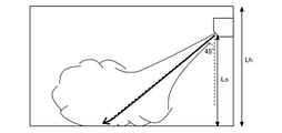
- FIG. 27 is a diagram showing the effect of the wind speed on the floor surface temperature in the conventional cooling start operation.
- FIG. 28 is a diagram showing the effect of the wind speed on the floor surface temperature in the cooling start-up operation according to the fourth embodiment.
- the air in the air-conditioned space can be efficiently cooled by avoiding the air-conditioned air from hitting the frame of the air-conditioned space.
- whether or not the air blown from the outlet 20d comes into contact with the floor surface is determined by the wind speed of the blown air, the temperature difference from the ambient air, and the wind direction.
- the ceiling height Lh of a general house is 2.4 m
- the height Lo of the outlet 20b of the indoor unit 2 is 2.2 m
- the wind direction is 45 degrees.
- FIG. 29 is a diagram showing the effect of the wind speed on the floor surface temperature in the conventional heating start-up operation.
- FIG. 30 is a diagram showing the effect of the wind speed on the floor surface temperature in the heating activation operation according to the fourth embodiment.
- Even in the heating start-up operation as shown in FIG. 29, conventionally, the wind speed of the air blown out from the outlet 20d increases and collides with the floor surface.
- the air-conditioned air can heat the air-conditioned space without colliding with the floor surface.
- the air volume control unit 52 of the present embodiment controls the indoor fan 22 based on the wind speed of the air blown from the outlet 20b in the cooling start operation and the heating start operation. Specifically, the air volume control unit 52 sets the air volume at the time of starting the indoor fan 22 so that the air speed of the air blown from the outlet 20b becomes 3.0 m / s or less in the cooling start operation and the heating start operation. do. Since the wind speed of the air blown out from the air outlet 20d is obtained from the air volume of the indoor fan 22 and the opening area of the air outlet 20b, the air volume at startup is determined from the wind speed of 3.0 m / s and the opening area of the air outlet 20b. Desired.
- the conditioned air is made to collide with the floor surface by setting the starting air volume of the indoor fan 22 so that the wind speed of the air blown from the outlet 20d is 3.0 m / s or less. It is possible to cool or heat the space to be air-conditioned. As a result, further high efficiency can be realized.
- Embodiment 5 The air conditioner 100 according to the fifth embodiment will be described.
- the air conditioner 100 of the fifth embodiment is different from the first embodiment in the control of the indoor fan 22 in the air volume control unit 52.
- the differences from the first embodiment will be described, and the configuration and control of the other air conditioner 100 will be the same as those of the first embodiment.
- FIG. 31 is a control block diagram of the air conditioner 100 according to the fifth embodiment.
- the air conditioner 100 of the fifth embodiment further includes a window position sensor 36, a vertical wind direction plate 231 and a left and right wind direction plate 232.
- the window position sensor 36 is provided in the housing of the indoor unit 2, and the vertical wind direction plate 231 and the left and right wind direction plates 232 are provided in the air outlet 20b of the indoor unit 2.
- the window position sensor 36 is a sensor that detects the temperature of the air-conditioned space and detects the position of the window in the air-conditioned space based on the detection result. Further, the window position sensor 36 of the present embodiment detects the position of the window having high heat insulation specifications. Specifically, the window position sensor 36 acquires a thermal image of the air-conditioned space and detects the position of the window from the thermal image. For example, a portion having a temperature difference from the wall surface is detected as a window. Then, when the temperature of the window is close to the indoor air temperature Ta, the position of the detected window is transmitted to the control device 5, assuming that the window has a high heat insulation specification.
- the vertical wind direction plate 231 has the same configuration as the wind direction plate 23 of the first embodiment, and adjusts the wind direction in the vertical direction.
- the left and right wind direction plates 232 are rotatably provided on the axis of rotation parallel to the vertical direction at the outlet 20b, and adjust the blowing direction of the conditioned air in the left-right direction.
- the left-right wind direction plate 232 is composed of a plurality of plates arranged at intervals in the left-right direction of the air outlet 20b, and each of the plurality of plates is rotatable.
- the angle of the left-right wind direction plate 232 is changed by controlling a stepping motor (not shown) attached to the rotating shaft by the control device 5.
- the plurality of left and right wind direction plates 232 may be adjusted to have the same angle, or each of the plurality of plates may be adjusted to have a different angle.
- the wind direction control unit 53 of the present embodiment controls the angle of the left and right wind direction plates 232 so that the air-conditioned air is blown to the window position when the window position is detected by the window position sensor 36 in the cooling start operation. .. Further, the wind direction control unit 53 sets the angle of the vertical wind direction plate 231 to an angle close to 90 degrees. This makes it possible to cool the air-conditioned space without cooling the skeleton.
- the wind direction control unit 53 controls the angle of the left and right wind direction plates 232 so that the air-conditioned air is blown to the position of the window when the position of the window is detected by the window position sensor 36 in the heating start operation. Further, the wind direction control unit 53 sets the angle of the vertical wind direction plate 231 to an angle close to 90 degrees. This makes it possible to heat the air in the air-conditioned space without heating the skeleton.
- the air volume control unit 52 of the present embodiment may increase the air volume of the indoor fan 22 when the position of the window is detected by the window position sensor 36 in the cooling start operation and the heating start operation.
- the wind direction is changed so that the blown air is directed to the position of the window.
- the room temperature can reach the set temperature at an early stage. This improves efficiency at startup and improves comfort.
- the air conditioning device 100 may further include a person detecting means for detecting the presence or absence of a resident in the air-conditioned space.
- the human detection means is an infrared sensor that acquires a thermal image, a camera that acquires an image, or the like.
- the control device 5 may raise the temperature of the blown air when there is no occupant in the air-conditioned space. This makes it possible to raise the evaporation temperature and improve the efficiency of the air conditioner 100.
- the control device 5 may lower the temperature of the blown air when there is no occupant in the air-conditioned space. This makes it possible to raise the condensation temperature and improve the efficiency of the air conditioner 100.
- the wind direction control unit 53 may set the angle of the wind direction plate 23 according to the presence or absence of a resident in the air-conditioned space during the cooling start operation and the heating start operation.
- the air conditioner 100 may start the cooling start operation or the heating start operation before the scheduled use of the air-conditioned space.
- the timing of starting the cooling start operation or the heating start operation is determined based on the GPS information of the occupants or the schedule information.
- the wall temperature sensor 34, the distance measuring sensor 35, and the window position sensor 36 in the above embodiment are not limited to those provided in the indoor unit 2, and may be provided separately from the indoor unit 2.
- the control device 5 has a communication function with an external device, receives the detection results of the wall temperature sensor 34, the distance measuring sensor 35, and the window position sensor 36, and performs the cooling start operation and the heating start operation. ..
Landscapes
- Engineering & Computer Science (AREA)
- Chemical & Material Sciences (AREA)
- Combustion & Propulsion (AREA)
- Mechanical Engineering (AREA)
- General Engineering & Computer Science (AREA)
- Physics & Mathematics (AREA)
- Fluid Mechanics (AREA)
- Air Conditioning Control Device (AREA)
Priority Applications (2)
| Application Number | Priority Date | Filing Date | Title |
|---|---|---|---|
| JP2022539872A JPWO2022024261A1 (https=) | 2020-07-29 | 2020-07-29 | |
| PCT/JP2020/029060 WO2022024261A1 (ja) | 2020-07-29 | 2020-07-29 | 空気調和装置 |
Applications Claiming Priority (1)
| Application Number | Priority Date | Filing Date | Title |
|---|---|---|---|
| PCT/JP2020/029060 WO2022024261A1 (ja) | 2020-07-29 | 2020-07-29 | 空気調和装置 |
Publications (1)
| Publication Number | Publication Date |
|---|---|
| WO2022024261A1 true WO2022024261A1 (ja) | 2022-02-03 |
Family
ID=80035507
Family Applications (1)
| Application Number | Title | Priority Date | Filing Date |
|---|---|---|---|
| PCT/JP2020/029060 Ceased WO2022024261A1 (ja) | 2020-07-29 | 2020-07-29 | 空気調和装置 |
Country Status (2)
| Country | Link |
|---|---|
| JP (1) | JPWO2022024261A1 (https=) |
| WO (1) | WO2022024261A1 (https=) |
Cited By (2)
| Publication number | Priority date | Publication date | Assignee | Title |
|---|---|---|---|---|
| CN119103672A (zh) * | 2024-10-15 | 2024-12-10 | 佛山市云米电器科技有限公司 | 基于出风时间的空调运行控制参数的生成方法及装置 |
| CN119737681A (zh) * | 2025-03-04 | 2025-04-01 | 浙江科技大学 | 一种空调送风附加式导流板智能控制系统及方法 |
Families Citing this family (1)
| Publication number | Priority date | Publication date | Assignee | Title |
|---|---|---|---|---|
| CN115419992B (zh) * | 2022-09-14 | 2024-08-09 | 珠海格力电器股份有限公司 | 空调器控制方法、装置、电子设备及可读介质 |
Citations (5)
| Publication number | Priority date | Publication date | Assignee | Title |
|---|---|---|---|---|
| JP2009139010A (ja) * | 2007-12-06 | 2009-06-25 | Sharp Corp | 空気調和機 |
| JP2010203699A (ja) * | 2009-03-04 | 2010-09-16 | Mitsubishi Electric Corp | 空気調和装置 |
| JP2014031907A (ja) * | 2012-08-01 | 2014-02-20 | Mitsubishi Electric Corp | 空気調和機 |
| JP2016050722A (ja) * | 2014-09-01 | 2016-04-11 | 日立アプライアンス株式会社 | 空気調和機 |
| JP2016200282A (ja) * | 2015-04-07 | 2016-12-01 | ジョンソンコントロールズ ヒタチ エア コンディショニング テクノロジー(ホンコン)リミテッド | 空気調和機及びその運転方法 |
Family Cites Families (7)
| Publication number | Priority date | Publication date | Assignee | Title |
|---|---|---|---|---|
| JPH10205856A (ja) * | 1997-01-20 | 1998-08-04 | Calsonic Corp | 空気調和装置 |
| JP5014376B2 (ja) * | 2009-04-30 | 2012-08-29 | 三菱電機株式会社 | 空気調和システム |
| JP2011112246A (ja) * | 2009-11-25 | 2011-06-09 | Mitsubishi Electric Corp | 空気調和機の室内機 |
| JP6161452B2 (ja) * | 2013-07-24 | 2017-07-12 | ジョンソンコントロールズ ヒタチ エア コンディショニング テクノロジー(ホンコン)リミテッド | 空調機システム |
| JP2016070575A (ja) * | 2014-09-30 | 2016-05-09 | 株式会社富士通ゼネラル | 空気調和装置 |
| JP6932002B2 (ja) * | 2017-02-13 | 2021-09-08 | 株式会社コロナ | 空気調和機 |
| JP2019113214A (ja) * | 2017-12-21 | 2019-07-11 | シャープ株式会社 | 空気調和機 |
-
2020
- 2020-07-29 WO PCT/JP2020/029060 patent/WO2022024261A1/ja not_active Ceased
- 2020-07-29 JP JP2022539872A patent/JPWO2022024261A1/ja not_active Ceased
Patent Citations (5)
| Publication number | Priority date | Publication date | Assignee | Title |
|---|---|---|---|---|
| JP2009139010A (ja) * | 2007-12-06 | 2009-06-25 | Sharp Corp | 空気調和機 |
| JP2010203699A (ja) * | 2009-03-04 | 2010-09-16 | Mitsubishi Electric Corp | 空気調和装置 |
| JP2014031907A (ja) * | 2012-08-01 | 2014-02-20 | Mitsubishi Electric Corp | 空気調和機 |
| JP2016050722A (ja) * | 2014-09-01 | 2016-04-11 | 日立アプライアンス株式会社 | 空気調和機 |
| JP2016200282A (ja) * | 2015-04-07 | 2016-12-01 | ジョンソンコントロールズ ヒタチ エア コンディショニング テクノロジー(ホンコン)リミテッド | 空気調和機及びその運転方法 |
Cited By (3)
| Publication number | Priority date | Publication date | Assignee | Title |
|---|---|---|---|---|
| CN119103672A (zh) * | 2024-10-15 | 2024-12-10 | 佛山市云米电器科技有限公司 | 基于出风时间的空调运行控制参数的生成方法及装置 |
| CN119103672B (zh) * | 2024-10-15 | 2025-10-03 | 佛山市云米电器科技有限公司 | 基于出风时间的空调运行控制参数的生成方法及装置 |
| CN119737681A (zh) * | 2025-03-04 | 2025-04-01 | 浙江科技大学 | 一种空调送风附加式导流板智能控制系统及方法 |
Also Published As
| Publication number | Publication date |
|---|---|
| JPWO2022024261A1 (https=) | 2022-02-03 |
Similar Documents
| Publication | Publication Date | Title |
|---|---|---|
| JP6328049B2 (ja) | 空調装置 | |
| JP5404777B2 (ja) | 空気調和装置 | |
| JP5389211B2 (ja) | 空調制御方法及び空調装置 | |
| JP5014376B2 (ja) | 空気調和システム | |
| JP5858062B2 (ja) | 空気調和システム | |
| JP6906311B2 (ja) | 空気調和装置 | |
| JP5984964B2 (ja) | 空気調和システム | |
| CN203771556U (zh) | 室内机和空气调节装置 | |
| JP5507231B2 (ja) | 空気調和機 | |
| US9410715B2 (en) | Air conditioning apparatus | |
| US20150276255A1 (en) | Air conditioning apparatus | |
| WO2022024261A1 (ja) | 空気調和装置 | |
| JPWO2019193639A1 (ja) | 空気調和システム | |
| KR20210131237A (ko) | 공기 조화 시스템 및 제어 방법 | |
| JP6019773B2 (ja) | 空気調和機の制御装置 | |
| JPH0650595A (ja) | 空気調和装置 | |
| WO2020156344A1 (zh) | 空调器 | |
| JPH1151445A (ja) | 輻射式空調システム | |
| WO2018042515A1 (ja) | 空気調和装置 | |
| WO2021214930A1 (ja) | 空気調和システムおよび制御方法 | |
| JP6049324B2 (ja) | 空気調和機 | |
| JP5797169B2 (ja) | 空気調和機 | |
| KR101622619B1 (ko) | 공기조화기 및 그 운전 방법 | |
| JP6562139B2 (ja) | 冷凍装置 | |
| WO2021181486A1 (ja) | 空調システム、空調制御装置、空調方法及びプログラム |
Legal Events
| Date | Code | Title | Description |
|---|---|---|---|
| 121 | Ep: the epo has been informed by wipo that ep was designated in this application |
Ref document number: 20946765 Country of ref document: EP Kind code of ref document: A1 |
|
| ENP | Entry into the national phase |
Ref document number: 2022539872 Country of ref document: JP Kind code of ref document: A |
|
| NENP | Non-entry into the national phase |
Ref country code: DE |
|
| 122 | Ep: pct application non-entry in european phase |
Ref document number: 20946765 Country of ref document: EP Kind code of ref document: A1 |