WO2022024261A1 - Air conditioning device - Google Patents
Air conditioning device Download PDFInfo
- Publication number
- WO2022024261A1 WO2022024261A1 PCT/JP2020/029060 JP2020029060W WO2022024261A1 WO 2022024261 A1 WO2022024261 A1 WO 2022024261A1 JP 2020029060 W JP2020029060 W JP 2020029060W WO 2022024261 A1 WO2022024261 A1 WO 2022024261A1
- Authority
- WO
- WIPO (PCT)
- Prior art keywords
- air
- temperature
- air volume
- indoor
- angle
- Prior art date
Links
Images


Classifications
-
- F—MECHANICAL ENGINEERING; LIGHTING; HEATING; WEAPONS; BLASTING
- F24—HEATING; RANGES; VENTILATING
- F24F—AIR-CONDITIONING; AIR-HUMIDIFICATION; VENTILATION; USE OF AIR CURRENTS FOR SCREENING
- F24F11/00—Control or safety arrangements
- F24F11/70—Control systems characterised by their outputs; Constructional details thereof
- F24F11/72—Control systems characterised by their outputs; Constructional details thereof for controlling the supply of treated air, e.g. its pressure
- F24F11/74—Control systems characterised by their outputs; Constructional details thereof for controlling the supply of treated air, e.g. its pressure for controlling air flow rate or air velocity
-
- F—MECHANICAL ENGINEERING; LIGHTING; HEATING; WEAPONS; BLASTING
- F24—HEATING; RANGES; VENTILATING
- F24F—AIR-CONDITIONING; AIR-HUMIDIFICATION; VENTILATION; USE OF AIR CURRENTS FOR SCREENING
- F24F11/00—Control or safety arrangements
- F24F11/70—Control systems characterised by their outputs; Constructional details thereof
- F24F11/72—Control systems characterised by their outputs; Constructional details thereof for controlling the supply of treated air, e.g. its pressure
- F24F11/79—Control systems characterised by their outputs; Constructional details thereof for controlling the supply of treated air, e.g. its pressure for controlling the direction of the supplied air
-
- Y—GENERAL TAGGING OF NEW TECHNOLOGICAL DEVELOPMENTS; GENERAL TAGGING OF CROSS-SECTIONAL TECHNOLOGIES SPANNING OVER SEVERAL SECTIONS OF THE IPC; TECHNICAL SUBJECTS COVERED BY FORMER USPC CROSS-REFERENCE ART COLLECTIONS [XRACs] AND DIGESTS
- Y02—TECHNOLOGIES OR APPLICATIONS FOR MITIGATION OR ADAPTATION AGAINST CLIMATE CHANGE
- Y02B—CLIMATE CHANGE MITIGATION TECHNOLOGIES RELATED TO BUILDINGS, e.g. HOUSING, HOUSE APPLIANCES OR RELATED END-USER APPLICATIONS
- Y02B30/00—Energy efficient heating, ventilation or air conditioning [HVAC]
- Y02B30/70—Efficient control or regulation technologies, e.g. for control of refrigerant flow, motor or heating
Definitions
- This disclosure relates to an air conditioner that regulates the temperature of a space such as a living space.
- Patent Document 1 discloses an air conditioner that raises the room temperature to a certain temperature or higher by performing convection heating with the wind direction diagonally downward and the maximum amount of air blown when the heating operation is started.
- the purpose of the conventional air conditioner is to quickly air-condition the air in the air-conditioned space and all the heat loads including the frame such as the wall and floor at the time of starting.
- the required air conditioning capacity becomes large, which leads to an increase in power consumption.
- the present disclosure is for solving the above-mentioned problems, and an object of the present disclosure is to provide an air conditioner capable of improving efficiency while maintaining comfort at startup.
- the air conditioner according to the present disclosure includes a heat exchanger that exchanges heat between air and a refrigerant, a fan that blows air heated or cooled by the heat exchanger into the air-conditioned space, and air blown into the air-conditioned space. It is equipped with a wind direction plate that changes the angle of the air conditioner and a control device that controls the air volume of the fan and the angle of the wind direction plate. Set the angle to be larger than the degree, set the angle of the wind direction plate to an angle smaller than 45 degrees when the vertical direction is 0 degree at the start of heating, and set the air volume of the fan to the maximum air volume at the start of cooling and the start of heating. It is set to a smaller start-up air volume.
- the air conditioner of the present disclosure it is possible to preferentially cool or heat the air in the air-conditioned space at the time of starting, and it is possible to improve the efficiency while maintaining the comfort at the time of starting. ..
- FIG. It is a schematic block diagram of the air conditioner which concerns on Embodiment 1.
- FIG. It is a control block diagram of the air conditioner which concerns on Embodiment 1.
- FIG. It is a figure which shows the operation at the time of the cooling operation of the indoor unit which concerns on Embodiment 1.
- FIG. It is a psychrometric chart which shows the state change of the air at the time of the cooling operation of the indoor unit which concerns on Embodiment 1.
- FIG. It is a figure which shows the operation at the time of the heating operation of the indoor unit which concerns on Embodiment 1.
- FIG. It is a psychrometric chart which shows the state change of the air at the time of the heating operation of the indoor unit which concerns on Embodiment 1.
- FIG. It is a figure which shows the heat load to the conventional house at the time of cooling. It is a figure which shows the heat load to a house in recent years at the time of cooling. It is a figure which shows the change of the air volume of an indoor fan in the conventional cooling start-up operation. It is a figure which shows the change of the air volume of the room fan in the cooling start operation which concerns on Embodiment 1.
- FIG. It is a figure which shows the change of the room air temperature and the wall temperature by the conventional cooling start operation. It is a figure which shows the change of the room air temperature and the wall temperature by the cooling start operation which concerns on Embodiment 1.
- FIG. It is a figure which shows the change of the power consumption of the air conditioner by the conventional cooling start operation.
- FIG. It is a figure which shows the change of the power consumption of the air conditioner by the cooling start operation which concerns on Embodiment 1.
- FIG. It is a figure which shows the influence of the wind direction and the air volume by the conventional cooling start operation. It is a figure which shows the influence of the wind direction and the air volume by the cooling start operation which concerns on Embodiment 1.
- FIG. It is a flowchart of the cooling start operation of the air conditioner which concerns on Embodiment 1.
- FIG. It is a figure which shows the heat load to the conventional house at the time of heating. It is a figure which shows the heat load to the house in recent years at the time of heating. It is a figure which shows the change of the room air temperature and the wall temperature by the conventional heating start-up operation.
- FIG. It is a figure which shows the change of the room air temperature and the wall temperature by the heating start operation which concerns on Embodiment 1.
- FIG. It is a figure which shows the influence of the wind direction and the air volume by the heating start operation which concerns on Embodiment 1.
- FIG. It is a flowchart of the heating start operation of the air conditioner which concerns on Embodiment 1.
- FIG. It is a control block diagram of the air conditioner which concerns on Embodiment 2.
- FIG. It is a flowchart of the cooling start operation of the air conditioner which concerns on Embodiment 3.
- FIG. It is a flowchart of the heating start operation of the air conditioner which concerns on Embodiment 3.
- FIG. It is a figure which shows the influence which the wind speed has on the floor surface temperature in the conventional cooling start-up operation.
- FIG. It is a figure which shows the influence which the wind speed has on the floor surface temperature in the cooling start operation which concerns on Embodiment 4.
- FIG. It is a figure which shows the influence which the wind speed has on the floor surface temperature in the conventional heating start-up operation. It is a figure which shows the influence which the wind speed has on the floor surface temperature in the heating start operation which concerns on Embodiment 4.
- FIG. It is a control block diagram of the air conditioner which concerns on Embodiment 5.
- FIG. 1 is a schematic configuration diagram of an air conditioner 100 according to the first embodiment.
- the air conditioner 100 of the first embodiment includes an outdoor unit 1 arranged outside the air-conditioned space and an indoor unit 2 arranged inside the air-conditioned space.
- the outdoor unit 1 and the indoor unit 2 are connected by wiring such as piping, a power supply, or a signal line.
- the outdoor unit 1 includes a compressor 11, a flow path switching valve 12, an outdoor heat exchanger 13, an expansion valve 14, and an outdoor fan 15.
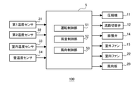
- the indoor unit 2 includes an indoor heat exchanger 21, an indoor fan 22, a wind direction plate 23, a first temperature sensor 31, a second temperature sensor 32, an indoor temperature sensor 33, a wall temperature sensor 34, and a control device. It is equipped with 5.
- the compressor 11, the flow path switching valve 12, the outdoor heat exchanger 13, the expansion valve 14, and the indoor heat exchanger 21 are connected by pipes to form a refrigerant circuit.
- the refrigerant circulating in the refrigerant circuit of the air conditioner 100 is, for example, a natural refrigerant such as carbon dioxide, hydrocarbon or helium, a chlorine-free refrigerant such as HFC410A or HFC407C, or a fluorocarbon-based refrigerant such as R22 or R134a.
- the compressor 11 is a fluid machine that sucks in a low-pressure gas refrigerant, compresses it, and discharges it as a high-pressure gas refrigerant.
- various types of compressors such as reciprocating engines, rotary engines, scrolls, and screws are used.
- the operating frequency of the compressor 11 is controlled by the control device 5.
- the flow path switching valve 12 is a four-way valve that switches between a cooling operation in which the outdoor heat exchanger 13 functions as a condenser and a heating operation in which the outdoor heat exchanger 13 functions as an evaporator.
- the flow path switching valve 12 is switched so that the refrigerant discharged from the compressor 11 flows into the outdoor heat exchanger 13 during the cooling operation, as shown by the solid line in FIG.
- the flow path switching valve 12 is switched so that the refrigerant discharged from the compressor 11 flows into the indoor heat exchanger 21 during the heating operation, as shown by the broken line in FIG.
- the outdoor heat exchanger 13 is, for example, a plate fin tube type heat exchanger that exchanges heat between the refrigerant flowing inside the circular tube or the flat tube and the air supplied by the outdoor fan 15.
- the outdoor heat exchanger 13 is arranged between the flow path switching valve 12 and the expansion valve 14.
- the outdoor heat exchanger 13 functions as an evaporator during the heating operation and as a condenser during the cooling operation.
- the expansion valve 14 is a valve that reduces the pressure of the refrigerant.
- the expansion valve 14 is an electronic expansion valve whose opening degree can be adjusted by the control device 5.
- the expansion valve 14 is arranged between the outdoor heat exchanger 13 and the indoor heat exchanger 21. Although the expansion valve 14 is arranged in the outdoor unit 1 in FIG. 1, it may be arranged in the indoor unit 2.
- the outdoor fan 15 sucks in the air outside the air-conditioned space, passes it through the outdoor heat exchanger 13, and blows it out of the air-conditioned space.
- the outdoor fan 15 is, for example, a propeller fan, a sirocco fan, or a cross-flow fan driven by a motor.
- the air volume of the outdoor fan 15 is controlled by controlling the rotation speed of the outdoor fan 15 by the control device 5.
- the control device 5 controls the air volume of the outdoor fan 15 by controlling the rotation speed by changing the current value.
- the control device 5 controls the air volume of the outdoor fan 15 by controlling the rotation speed by changing the power supply frequency by inverter control.
- the indoor heat exchanger 21 is, for example, a plate fin tube type heat exchanger, and exchanges heat between the refrigerant circulating inside the circular tube or the flat tube and the air blown by the indoor fan 22.
- the indoor heat exchanger 21 is arranged between the expansion valve 14 and the flow path switching valve 12.
- the indoor heat exchanger 21 functions as a condenser during the heating operation and as an evaporator during the cooling operation.
- the indoor fan 22 sucks in the air in the air-conditioned space, passes it through the indoor heat exchanger 21, and blows it out into the air-conditioned space.
- the indoor fan 22 is, for example, a propeller fan, a sirocco fan, or a cross-flow fan driven by a motor.
- the air volume of the indoor fan 22 is controlled by controlling the rotation speed of the indoor fan 22 by the control device 5.
- the control device 5 controls the air volume of the indoor fan 22 by controlling the rotation speed by changing the current value.
- the control device 5 controls the air volume of the indoor fan 22 by controlling the rotation speed by changing the power supply frequency by inverter control.
- one indoor fan 22 is arranged upstream of the indoor heat exchanger 21 in the air flow, but if the target air volume can be obtained, the arrangement and number of the indoor fans 22 are shown in FIG. It is not limited to the example of 1.
- the indoor fan 22 may be arranged downstream of the indoor heat exchanger 21, or a plurality of indoor fans 22 may be arranged upstream and downstream of the indoor heat exchanger 21, respectively.
- the indoor unit 2 is a wall-mounted indoor unit that can be attached to the wall of the air-conditioned space.
- the housing of the indoor unit 2 is provided with a suction port 20a and an outlet 20b.
- the air in the air-conditioned space is sucked by the indoor fan 22 from the suction port 20a, cooled or heated by the indoor heat exchanger 21, and blown out to the air-conditioned space from the air outlet 20b.
- the wind direction plate 23 is rotatably provided on a rotation axis parallel to the horizontal direction at the outlet 20b, and adjusts the blowing direction of the conditioned air cooled or heated by the indoor heat exchanger 21 in the vertical direction.
- the angle of the wind direction plate 23 is an angle when the vertical direction is 0 degrees when the indoor unit 2 is installed on the wall of the air-conditioned space.
- the first temperature sensor 31 is provided in the pipe connecting the indoor heat exchanger 21 and the expansion valve 14, and detects the temperature of the refrigerant on the inlet side of the indoor heat exchanger 21 during the cooling operation.
- the second temperature sensor 32 is provided in the pipe connecting the indoor heat exchanger 21 and the flow path switching valve 12, and detects the temperature of the refrigerant on the outlet side of the indoor heat exchanger 21 during the cooling operation. The refrigerant temperature detected by the first temperature sensor 31 and the second temperature sensor 32 is transmitted to the control device 5.
- the indoor temperature sensor 33 is arranged around the suction port 20a and detects the temperature of the air sucked into the indoor unit 2 from the air-conditioned space.
- the indoor air temperature Ta detected by the indoor temperature sensor 33 is transmitted to the control device 5.
- the wall temperature sensor 34 is provided in the housing of the indoor unit 2 and detects the temperature of the wall in the air-conditioned space. Specifically, the wall temperature sensor 34 detects the temperature of the wall facing the indoor unit 2 and located in the direction of blowing out the conditioned air of the indoor unit 2.
- the wall temperature sensor 34 is, for example, an infrared sensor such as a thermopile sensor that can measure the temperature of an object in a non-contact manner.
- the wall temperature Tw detected by the wall temperature sensor 34 is transmitted to the control device 5.
- the control device 5 is a microcomputer equipped with a CPU, ROM, RAM, an I / O port, and the like.
- the control device 5 adjusts the air based on the instruction from the user input via the remote control or the like and the detection results of the first temperature sensor 31, the second temperature sensor 32, the indoor temperature sensor 33, and the wall temperature sensor 34. It controls the operation of the entire device 100.
- the control device 5 is provided in the indoor unit 2 in FIG. 1, it may be provided in the outdoor unit 1, or the outdoor unit 1 and the indoor unit 2 are provided with individual control devices 5 to communicate with each other. It may be configured to be used.
- FIG. 2 is a control block diagram of the air conditioner 100 according to the first embodiment.
- the control device 5 of the air conditioner 100 has an operation control unit 51, an air volume control unit 52, and a wind direction control unit 53 as functional units.
- Each functional unit is realized by the control device 5 executing a program, or is realized by a dedicated processing circuit.
- the operation control unit 51 performs cooling operation and heating based on the setting information input via the remote control or the like and the detection results of the first temperature sensor 31, the second temperature sensor 32, the room temperature sensor 33, and the wall temperature sensor 34. Perform driving.
- the input setting information is, for example, a cooling operation, a heating operation setting, and a set temperature Tn.
- the operation control unit 51 controls the operation frequency of the compressor 11, the switching of the flow path switching valve 12, the opening degree of the expansion valve 14, and the rotation speed of the outdoor fan 15 based on the setting information and the detection result of each temperature sensor. ..
- the air volume control unit 52 controls the air volume of the indoor fan 22 based on the setting information input via the remote controller or the like and the temperature detected by the indoor temperature sensor 33 and the wall temperature sensor 34.
- the wind direction control unit 53 controls the angle of the wind direction plate 23 based on the setting information input via the remote controller or the like.
- the operation of the air conditioner 100 during the cooling operation will be described.
- the refrigerant compressed by the compressor 11 and turned into a high-temperature and high-pressure gas flows into the outdoor heat exchanger 13 that functions as a condenser.
- the refrigerant undergoes a phase change from a high-temperature, high-pressure gas to a liquid in the outdoor heat exchanger 13, and heats the air passing through the outdoor heat exchanger 13.
- the refrigerant is depressurized by the expansion valve 14 set to have a small opening degree, becomes a two-phase state in which a low-temperature low-pressure liquid and a gas are mixed, and flows into the indoor heat exchanger 21 functioning as an evaporator.
- the refrigerant phase changes from a liquid to a gas and cools the air passing through the indoor heat exchanger 21. After that, the refrigerant flows into the compressor 11 and becomes a high-temperature and high-pressure gas again.
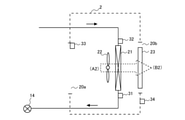
- FIG. 3 is a diagram showing the operation of the indoor unit 2 according to the first embodiment during the cooling operation.
- the control device 5 sets the opening degree of the expansion valve 14 to be small.
- the pressure of the refrigerant flowing into the indoor heat exchanger 21 decreases.
- the degree of superheat calculated from the difference between the inlet temperature of the refrigerant detected by the first temperature sensor 31 and the outlet temperature of the refrigerant detected by the second temperature sensor 32 becomes a predetermined value.
- the opening degree of the expansion valve 14 is controlled.
- the air (A1) in the air-conditioned space is supplied by the indoor fan 22 to the indoor heat exchanger 21 that functions as an evaporator.
- the indoor heat exchanger 21 cools the passing air.
- the cooled conditioned air (B1) is supplied into the conditioned space.
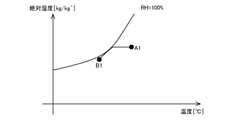
- FIG. 4 is a psychrometric chart showing a change in the state of air during the cooling operation of the indoor unit 2 according to the first embodiment.
- the horizontal axis of FIG. 4 represents temperature (° C.), and the vertical axis represents absolute humidity (kg / kg').
- Points A1 and B1 in FIG. 4 correspond to the positions (A1) and (B1) in FIG. 3, respectively.
- the air (A1) that has passed through the indoor heat exchanger 21 is cooled and dehumidified by heat exchange with the refrigerant, and is in a low temperature and high relative humidity state, and then in a state in which the absolute humidity is lowered (A). It becomes B1) and is supplied as air supply to the air-conditioned space.
- Heating operation The operation of the air conditioner 100 during the heating operation will be described.
- the refrigerant compressed by the compressor 11 and turned into a high-temperature and high-pressure gas flows into the indoor heat exchanger 21 that functions as a condenser.
- the refrigerant undergoes a phase change from a high-temperature, high-pressure gas to a liquid in the indoor heat exchanger 21, and heats the air passing through the indoor heat exchanger 21.
- the refrigerant is depressurized by the expansion valve 14 whose opening degree is set small, becomes a two-phase state in which a low-temperature low-pressure liquid and a gas are mixed, and flows into the outdoor heat exchanger 13 functioning as an evaporator.
- the refrigerant changes phase from a liquid to a gas and cools the air passing through the outdoor heat exchanger 13.
- the refrigerant flows into the compressor 11 and becomes a high-temperature and high-pressure gas again.
- FIG. 5 is a diagram showing the operation of the indoor unit 2 according to the first embodiment during the heating operation.
- the control device 5 sets the opening degree of the expansion valve 14 to be small. As a result, the pressure of the refrigerant flowing into the outdoor heat exchanger 13 decreases. Further, the control device 5 opens the expansion valve 14 so that the supercooling degree calculated from the difference between the outlet temperature of the refrigerant detected by the second temperature sensor 32 and the condensation temperature of the refrigerant becomes a predetermined value. Control the degree.
- the air (A2) in the air-conditioned object is supplied to the indoor heat exchanger 21 functioning as a condenser by the indoor fan 22.
- the indoor heat exchanger 21 heats the passing air. After that, the heated conditioned air (B2) is supplied to the conditioned space.
- FIG. 6 is a psychrometric chart showing a change in the air state during the heating operation of the indoor unit 2 according to the first embodiment.
- the horizontal axis of FIG. 6 represents temperature (° C.), and the vertical axis represents absolute humidity (kg / kg').
- Points A2 and B2 in FIG. 6 correspond to the positions (A2) and (B2) in FIG. 5, respectively.
- the air (A2) that has passed through the indoor heat exchanger 21 is heated by heat exchange with the refrigerant, becomes a high temperature state (B2), and is supplied to the air-conditioned space as supply air.
- the cooling start-up operation in the present embodiment will be described.
- the air volume and direction of the air-conditioned air are controlled so as to realize a highly efficient and high-capacity operating state for the air-conditioned space and to reach the set temperature at an early stage. ..
- the air volume of the room fan 22 is set to be larger than that when the room temperature is stable, and the wind direction of the conditioned air is the center of the room or 45. It was set every time.
- FIG. 7 is a diagram showing a heat load on a conventional house during cooling
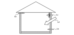
- FIG. 8 is a diagram showing a heat load on a recent house during cooling.
- the arrows in FIGS. 7 and 8 indicate the heat load, and the size of the arrow indicates the magnitude of the heat load.
- the heat load related to the house includes a once-through heat load La generated from a temperature difference from the outside, a ventilation load Lb due to draft, a heat load Lc due to mechanical ventilation, and solar radiation.
- the once-through heat load La is reduced as compared with the conventional case.
- the ventilation load Lb is reduced as compared with the conventional case. That is, in recent years, as the heat load during cooling, the heat load Lc due to mechanical ventilation and the heat load Ld due to solar radiation are the main factors, and the heat load La and the ventilation load Lb, which are heat loads from the wall surface, are greatly reduced. is doing.
- the room temperature was reached to the target temperature by increasing the air volume and cooling the air-conditioned space including the skeleton such as the wall and the floor.
- the heat load from the wall surface is smaller than before, and the heat load does not change significantly even if the difference between the outside air temperature and the room temperature becomes large. Therefore, in the air conditioner 100 of the present embodiment, at the time of starting the cooling operation, the cooling start operation of giving priority to the air temperature of the air-conditioned space is performed.
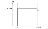
- FIG. 9 is a diagram showing changes in the air volume of the indoor fan in the conventional cooling start operation.
- FIG. 10 is a diagram showing changes in the air volume of the indoor fan 22 in the cooling start-up operation according to the first embodiment.
- the horizontal axis of FIGS. 9 and 10 shows time, and the vertical axis shows the air volume of the indoor fan 22.
- the "cooling start operation” is defined as an operation from the start of the cooling operation to the time when the indoor air temperature Ta reaches the set temperature Tn.
- the air volume of the indoor fan is set to the maximum air volume at t0 at the start of the cooling operation, and the air volume of the indoor fan is reduced at the time tun when the set temperature Tn is reached. ..
- the air volume control unit 52 sets the air volume of the indoor fan 22 to the start air volume at t0 at the start of the cooling operation.
- the start-up air volume is an air volume set to lower only the temperature of the air in the air-conditioned space, and is set so that the air blown out from the outlet 20b does not directly hit the wall or the floor.
- the air volume at startup is equal to or greater than the air volume according to the lower limit of the rotation speed of the motor of the indoor fan 22, and is smaller than the maximum air volume of the indoor fan 22.
- the start-up air volume is, for example, an air volume at which the reach of the air blown from the outlet 20b is equal to or less than the distance to the wall surface facing the indoor unit 2.
- the reachable distance is, for example, the distance from the outlet 20b to a place where the velocity of the blown air is 0.25 m / s.
- the starting air volume is set to 80% of the maximum air volume.
- the start-up air volume may be a constant value regardless of the difference between the start-up indoor air temperature Ta and the set temperature Tn, or may be a constant value depending on the difference between the start-up indoor air temperature Ta and the set temperature Tn. Different air volumes may be set. However, in any case, the air volume at startup is set to be smaller than the maximum air volume of the indoor fan 22.
- the reach of the air blown out from the outlet 20b can be shortened, and the air temperature in the air-conditioned space can be selectively lowered. ..
- the skeleton such as the wall and the floor in order to lower the indoor air temperature Ta to the set temperature Tn, so that the required air conditioning capacity can be reduced.
- the air volume control unit 52 increases the air volume of the indoor fan 22 when the indoor air temperature Ta detected by the indoor temperature sensor 33 approaches the set temperature Tn.
- the efficiency of the refrigeration cycle of the air conditioner 100 can be improved, and the comfort and comfort can be improved. Energy saving is improved.
- the air volume control unit 52 sets the air volume of the indoor fan 22 to the maximum air volume when the time tun is reached, that is, when the indoor air temperature Ta detected by the indoor temperature sensor 33 reaches the set temperature Tn.
- the air volume control unit 52 sets the air volume of the indoor fan 22 as the maximum air volume until the wall temperature Tw detected by the wall temperature sensor 34 becomes equal to the indoor air temperature Ta.
- the entire space including the skeleton of the air-conditioned space is cooled.
- the influence of radiant heat from the skeleton is reduced and the comfort is improved.
- FIG. 11 is a diagram showing changes in the indoor air temperature Ta and the wall temperature Tw due to the conventional cooling start operation.
- FIG. 12 is a diagram showing changes in the indoor air temperature Ta and the wall temperature Tw due to the cooling start-up operation according to the first embodiment.
- the horizontal axis of FIGS. 11 and 12 indicates time, and the vertical axis indicates temperature.
- the air in the air-conditioned space and the skeleton are targeted for cooling, so that the indoor air temperature Ta and the wall temperature Tw are similarly lowered.
- the indoor air temperature Ta first drops to the set temperature Tn, and then the wall temperature. Tw goes down.
- FIG. 13 is a diagram showing changes in the power consumption of the air conditioner due to the conventional cooling start operation.
- FIG. 14 is a diagram showing a change in power consumption of the air conditioner 100 due to the cooling start operation according to the first embodiment.
- the horizontal axis of FIGS. 13 and 14 shows time, and the vertical axis shows the power consumption of the air conditioner 100.
- the air volume of the indoor fan 22 is set to the start air volume smaller than the maximum air volume, so that the set temperature Tn is reached from t0 at the start of the cooling operation.
- the power consumption up to the time tun can be made lower than that of the conventional example.
- the air volume of the indoor fan 22 at the start of the cooling operation is reduced by the control of the air volume control unit 52, so that the wind speed of the air blown out from the outlet 20b is lowered. Therefore, at the time of the cooling start operation of the present embodiment, the influence of the vertical movement of the conditioned air due to the density difference becomes larger than that at the time of the conventional cooling start operation.
- the temperature of the air blown out from the outlet 20b during the cooling operation is lower than the air temperature of the air-conditioned space. Therefore, the density of the air blown out from the outlet 20b during the cooling operation becomes higher than that of the surroundings, and the wind direction changes in the downward direction.
- the wind direction control unit 53 sets the angle ⁇ of the wind direction plate 23 so that the blowing direction of the conditioned air becomes larger than 45 degrees when the vertical direction is 0 degree in the cooling start operation. Specifically, the angle ⁇ of the wind direction plate 23 is set to be larger than 45 degrees when the vertical direction is 0 degrees.
- the wind direction control unit 53 may set the angle ⁇ of the wind direction plate 23 to any angle between 45 degrees and 90 degrees (horizontal direction). As a result, the cold air does not cool the ceiling surface, and the conditioned air can be efficiently diffused into the conditioned space. Further, as the angle ⁇ of the wind direction plate 23 is set to be larger than 45 degrees, the air volume at the time of starting the indoor fan 22 is set to be large, so that cold air can be efficiently supplied to the air-conditioned space.
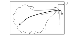
- FIG. 15 is a diagram showing the influence of the wind direction and the air volume due to the conventional cooling start operation.
- FIG. 16 is a diagram showing the effects of the wind direction and the air volume due to the cooling start-up operation according to the first embodiment.
- 15 and 16 are views of the air-conditioned space in which the indoor unit 2 is installed, as viewed from the side.
- the air volume of the indoor fan becomes the maximum air volume, so that the air blown out from the air outlet directly hits the wall and the floor, and the entire air-conditioned space including the skeleton is covered. It will be cooled.
- FIG. 15 is a diagram showing the influence of the wind direction and the air volume due to the conventional cooling start operation.
- FIG. 16 is a diagram showing the effects of the wind direction and the air volume due to the cooling start-up operation according to the first embodiment.
- 15 and 16 are views of the air-conditioned space in which the indoor unit 2 is installed, as viewed from the side.
- the air volume of the indoor fan becomes the maximum air volume, so that the air
- the air volume of the indoor fan 22 is set to be smaller than the maximum air volume, and the angle ⁇ of the wind direction plate 23 is set to be larger than 45 degrees.
- the air blown out from the outlet 20b is circulated in the air-conditioned space without hitting the wall, and the air in the air-conditioned space can be preferentially cooled.
- FIG. 17 is a flowchart of the cooling start operation of the air conditioner 100 according to the first embodiment.
- the flowchart of FIG. 17 is executed by the control device 5 when the start of the cooling operation is instructed.
- the angle ⁇ of the wind direction plate 23 is set to be larger than 45 degrees by the wind direction control unit 53 (S11).
- the air volume of the indoor fan 22 is set to the air volume at startup by the air volume control unit 52 (S12).
- the air volume at startup is smaller than the maximum air volume of the indoor fan 22.
- the air volume control unit 52 determines whether or not the indoor air temperature Ta detected by the indoor temperature sensor 33 has approached the set temperature Tn. Specifically, it is determined whether or not the difference between the indoor air temperature Ta and the set temperature Tn is equal to or less than the threshold value ⁇ (S13).
- ⁇ is a preset threshold value, for example, 2 ° C.
- the cooling operation at the start-up air volume is continued.
- the difference between the indoor air temperature Ta and the set temperature Tn is equal to or less than the threshold value ⁇ (S13: YES)
- the air volume of the indoor fan 22 is increased from the starting air volume (S14).
- the air volume control unit 52 determines whether or not the indoor air temperature Ta detected by the indoor temperature sensor 33 is equal to or lower than the set temperature Tn (S15).
- the indoor air temperature Ta is higher than the set temperature Tn (S15: NO)
- the cooling operation is continued while increasing the air volume.
- the indoor air temperature Ta becomes equal to or less than the set temperature Tn (S15: YES)
- the air volume of the indoor fan 22 is set to the maximum air volume (S16).
- the air volume control unit 52 determines whether or not the wall temperature Tw detected by the wall temperature sensor 34 is equal to or lower than the indoor air temperature Ta (S17).
- the wall temperature Tw is higher than the indoor air temperature Ta (S17: NO)
- the cooling operation at the maximum air volume is continued.
- the wall temperature Tw becomes equal to or lower than the indoor air temperature Ta (S17: YES)
- normal control is performed (S18). In the normal control, the air volume of the indoor fan 22 is reduced from the maximum air volume, and feedback control is performed for the indoor air temperature Ta and the wall temperature Tw to maintain the set temperature Tn.
- the heating activation operation in the present embodiment will be described.
- the air-conditioned air is used so as to realize a highly efficient and high-capacity operating state for the air-conditioned space and to reach the set temperature at an early stage, as in the case of the cooling operation.
- the air volume and direction were controlled. For example, when the difference between the room temperature and the set temperature is large at the start of the heating operation, the air volume of the room fan 22 is set larger than that when the room temperature is stable, and the wind direction of the conditioned air is set at the center of the room. It had been.
- the heating operation if the temperature of the conditioned air blown out is lower than the body temperature, a draft feeling is generated for the user, so it is necessary to raise the temperature of the conditioned air for the purpose of maintaining comfort, and the condensation temperature. In order to increase the temperature, the efficiency deteriorated.
- FIG. 18 is a diagram showing a heat load on a conventional house during heating
- FIG. 19 is a diagram showing a heat load on a house in recent years during heating.
- the arrows in FIGS. 18 and 19 indicate the heat load, and the size of the arrow indicates the magnitude of the heat load.
- the heat load related to the house includes a once-through heat load La generated from a temperature difference from the outside, a ventilation load Lb due to draft, and a heat load Lc due to mechanical ventilation.
- the once-through heat load La is reduced as compared with the conventional case.
- the ventilation load Lb is reduced as compared with the conventional case. That is, in recent years, as the heat load during heating, the heat load Lc due to mechanical ventilation is the main factor, and the once-through heat load La and the ventilation load Lb, which are the heat loads from the wall surface, are greatly reduced. Since solar radiation is a heating source, it does not function as a load during heating. Therefore, the total amount of the heating load is greatly reduced as compared with the case of cooling.
- the air volume control unit 52 controls the air volume of the indoor fan 22 at the time of starting, as shown in FIG. 10, as in the case of the cooling start operation. Specifically, the air volume control unit 52 sets the air volume of the indoor fan 22 to the air volume at startup at t0 at the start of heating operation.
- the start-up air volume is an air volume set to lower only the temperature of the air in the air-conditioned space, similar to the start-up air volume in the cooling start-up operation, and the air blown from the outlet 20b is sent to the wall or the floor. The air volume is set so that it does not hit directly.
- the air volume at startup is equal to or greater than the air volume according to the lower limit of the rotation speed of the motor of the indoor fan 22, and is smaller than the maximum air volume of the indoor fan 22.
- the start-up air volume during the heating operation may be the same as the start-up air volume during the cooling start-up operation, or may be a different air volume.
- the reach of the air blown out from the outlet 20b can be shortened, and the air temperature in the air-conditioned space can be selectively raised. ..
- the skeleton such as the wall and the floor in order to raise the indoor air temperature Ta to the set temperature Tn, so that the required air conditioning capacity can be reduced.
- the air volume control unit 52 increases the air volume of the indoor fan 22 when the indoor air temperature Ta detected by the indoor temperature sensor 33 approaches the set temperature Tn.
- the efficiency of the air conditioner 100 can be improved by gradually heating the skeleton such as walls and floors, and comfort and energy saving can be achieved. Improves sex.
- the air volume control unit 52 sets the air volume of the indoor fan 22 to the maximum air volume when the time tun is reached, that is, when the indoor air temperature Ta detected by the indoor temperature sensor 33 reaches the set temperature Tn.
- the air volume control unit 52 sets the air volume of the indoor fan 22 as the maximum air volume until the wall temperature Tw detected by the wall temperature sensor 34 becomes equal to the indoor air temperature Ta.
- the entire space including the skeleton of the air-conditioned space is heated.
- the influence of heat leakage from the skeleton is reduced and the comfort is improved.
- FIG. 20 is a diagram showing changes in the indoor air temperature Ta and the wall temperature Tw due to the conventional heating start-up operation.
- FIG. 21 is a diagram showing changes in the indoor air temperature Ta and the wall temperature Tw due to the heating activation operation according to the first embodiment.
- the horizontal axis of FIGS. 20 and 21 indicates time, and the vertical axis indicates temperature.
- the indoor air temperature Ta and the wall temperature Tw rise in the same manner because the air in the air-conditioned space and the skeleton are targeted for heating.
- the indoor air temperature Ta first rises to the set temperature Tn, and then the wall.
- the temperature Tw rises.
- the change in the power consumption of the air conditioner due to the conventional heating start operation is the same as in FIG. 13, and the change in the power consumption of the air conditioner 100 due to the heating start operation according to the first embodiment is the same as in FIG. be.
- the heating start-up operation of the present embodiment the power consumption from t0 at the start of the heating operation to the time tn when the set temperature Tn is reached can be reduced as compared with the conventional example.
- the air volume of the indoor fan 22 at the time of starting heating is reduced by the control of the air volume control unit 52, so that the wind speed of the conditioned air blown out from the outlet 20b is lowered. Therefore, in the heating start operation of the present embodiment, the influence of the vertical movement of the conditioned air due to the density difference becomes larger than that in the conventional heating start operation.
- the temperature of the air blown out from the outlet 20b during the heating operation is higher than the air temperature of the air-conditioned space. Therefore, the density of the air blown out from the outlet 20b during the heating operation is lower than that of the surroundings, and the wind direction changes in the ascending direction.
- the wind direction control unit 53 sets the angle ⁇ of the wind direction plate 23 so that the blowing direction of the conditioned air is smaller than 45 degrees when the vertical direction is 0 degree in the heating start operation. Specifically, the angle ⁇ of the wind direction plate 23 is set to be smaller than 45 degrees when the vertical direction is 0 degrees.
- the wind direction control unit 53 may set the angle ⁇ of the wind direction plate 23 to any angle between 0 degree (vertical direction) and 45 degrees. As a result, warm air does not stay on the ceiling surface, and the conditioned air can be efficiently diffused in the conditioned space.
- the temperature of the conditioned air is often high for the purpose of maintaining comfort, so the difference between the conditioned air temperature and the ambient air temperature tends to be larger than in the case of cooling. Therefore, by setting the angle ⁇ of the wind direction plate 23 to an angle close to 45 degrees in the heating start operation, it is possible to efficiently heat the air-conditioned space as compared with the case of cooling. Furthermore, by setting the angle ⁇ of the wind direction plate 23 to an angle close to 45 degrees, convection near the floor surface can be suppressed, and the amount of heat supplied to the underfloor space decreases, thus accelerating the rise in room temperature. It is also possible to make it. Further, as the angle of the wind direction plate 23 is set smaller than 45 degrees, the air volume at the time of starting the indoor fan 22 is set smaller, so that warm air can be efficiently supplied to the air-conditioned space.
- FIG. 22 is a diagram showing the influence of the wind direction and the air volume due to the heating activation operation according to the first embodiment.
- the air volume of the indoor fan 22 is set to be smaller than the maximum air volume, and the angle ⁇ of the wind direction plate 23 is set to be smaller than 45 degrees.
- the air blown out from the outlet 20b is circulated in the air-conditioned space without hitting the wall. As a result, the air in the air-conditioned space can be preferentially cooled.
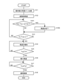
- FIG. 23 is a flowchart of the heating start operation of the air conditioner 100 according to the first embodiment.
- the flowchart of FIG. 23 is executed by the control device 5 when the start of the heating operation is instructed.
- the angle ⁇ of the wind direction plate 23 is set to be smaller than 45 degrees by the wind direction control unit 53 (S21).
- the air volume of the indoor fan 22 is set to the air volume at startup by the air volume control unit 52 (S22).
- the air volume at startup is smaller than the maximum air volume of the indoor fan 22.
- the air volume control unit 52 determines whether or not the indoor air temperature Ta detected by the indoor temperature sensor 33 has approached the set temperature Tn. Specifically, it is determined whether or not the difference between the set temperature Tn and the indoor air temperature Ta is equal to or less than the threshold value ⁇ (S23).
- ⁇ is a preset threshold value, for example, 2 ° C.
- the air volume control unit 52 determines whether or not the indoor air temperature Ta detected by the indoor temperature sensor 33 is equal to or higher than the set temperature Tn (S25).
- the indoor air temperature Ta is less than the set temperature Tn (S25: NO)
- the heating operation is continued while increasing the air volume.
- the indoor air temperature Ta becomes equal to or higher than the set temperature Tn (S25: YES)
- the air volume of the indoor fan 22 is set to the maximum air volume (S26).
- the air volume control unit 52 determines whether or not the wall temperature Tw detected by the wall temperature sensor 34 is equal to or higher than the indoor air temperature Ta (S27).
- the wall temperature Tw is less than the indoor air temperature Ta (S27: NO)
- the heating operation at the maximum air volume is continued.
- the wall temperature Tw becomes equal to or higher than the indoor air temperature Ta (S27: YES)
- normal heating control is performed (S28). In normal heating control, the air volume of the indoor fan 22 is reduced from the maximum air volume, and feedback control is performed so that the indoor air temperature Ta and the wall temperature Tw maintain the set temperature Tn.
- the air conditioning target space is different from the conventional control of cooling or heating both the skeleton and the air of the air conditioning target space in the cooling start operation and the heating start operation.
- Air is preferentially cooled or heated.
- the cooling capacity or heating capacity required to cool or heat the air temperature of the air-conditioned space to the set temperature is smaller than that of the conventional start-up operation, so that power consumption can be reduced and efficiency is improved. do.
- the air temperature in the air-conditioned space can be cooled or heated to a set temperature, and comfort can be maintained.
- the influence of the buoyancy of the air-conditioned air blown out can be reduced, and the entire air-conditioned space can be uniformly air-conditioned, which is comfortable. Improves sex.
- the main purpose is to prevent the conditioned air from coming into contact with the skeleton at the time of starting, and it is better that not only the air outlet 20b but also the air around the suction port 20a does not come into contact with the wall surface as much as possible.
- the start-up air volume of the indoor fan 22 is set to be smaller than the maximum air volume, it is possible to reduce the wind speed near the wall surface from the air sucked from the suction port 20a, and further, the air in the air-conditioned space. Can be prioritized for air conditioning.
- Embodiment 2 The air conditioner 100 according to the second embodiment will be described.
- the air conditioner 100 of the second embodiment is different from the first embodiment in the control of the wind direction plate 23 by the wind direction control unit 53.
- the differences from the first embodiment will be described, and the configuration and control of the other air conditioner 100 will be the same as those of the first embodiment.
- FIG. 24 is a control block diagram of the air conditioner 100 according to the second embodiment.
- the air conditioner 100 of the second embodiment further includes a distance measuring sensor 35 that measures the distance between the wall defining the air-conditioned space and the indoor unit 2.
- the control device 5 of the air conditioner 100 is an angle calculation unit that calculates the angle of the wind direction plate 23 during the start-up operation (hereinafter referred to as “start-up angle”) based on the distance measured by the distance measurement sensor 35. Further has 54.
- the distance measuring sensor 35 is an optical phase type distance measuring sensor or an ultrasonic type distance measuring sensor.
- the distance measuring sensor 35 is attached to the housing of the indoor unit 2 and measures the distance to the wall surface facing the indoor unit 2 and the installation height of the indoor unit 2. The distance measured by the distance measuring sensor 35 is transmitted to the control device 5.
- the angle calculation unit 54 of the control device 5 is activated by a line connecting the floor surface and the lower end of the opposite wall surface from the position of the air outlet 20b based on the distance to the wall surface and the installation height measured by the distance measuring sensor 35. Calculate the hour angle ⁇ d.
- the start-up angle ⁇ d calculated by the angle calculation unit 54 is transmitted to the wind direction control unit 53.
- the wind direction control unit 53 sets the angle ⁇ of the wind direction plate 23 so that the blowing direction of the air-conditioning air becomes larger than the starting angle ⁇ d when the vertical direction is 0 degree in the cooling start operation. Specifically, when the vertical direction is 0 degree, the angle ⁇ of the wind direction plate 23 is set to be larger than the start-up angle ⁇ d and 90 degrees or less. Further, the wind direction control unit 53 sets the angle ⁇ of the wind direction plate 23 so that the blowing direction of the conditioned air is smaller than the starting angle ⁇ d when the vertical direction is 0 degree in the heating start operation. Specifically, the angle of the wind direction plate 23 is set to be smaller than the starting angle ⁇ d and 0 degrees or more.
- the air-conditioned space can be cooled or heated more efficiently by setting the blowing direction of the air-conditioned air at the time of starting according to the size of the air-conditioned space.
- the method of obtaining the start-up angle ⁇ d is not limited to the above.
- the distance to the wall surface facing the indoor unit 2 and the installation height may be input by the user, and the starting angle ⁇ d may be obtained based on the input information.
- the startup angle ⁇ d may be directly input by the user.
- an image of the air-conditioned space may be acquired by an image acquisition device such as a camera, and the starting angle ⁇ d may be obtained by image analysis.
- Embodiment 3 The air conditioner 100 according to the third embodiment will be described.
- the air conditioner 100 of the third embodiment is different from the first embodiment in the control of the indoor fan 22 in the air volume control unit 52.
- the differences from the first embodiment will be described, and the configuration and control of the other air conditioner 100 will be the same as those of the first embodiment.
- the air volume control unit 52 of the present embodiment controls the air volume of the indoor fan 22 in the cooling start operation and the heating start operation based on the wall temperature Tw detected by the wall temperature sensor 34. Specifically, in the cooling start-up operation, the air volume control unit 52 controls the air volume of the indoor fan 22 so that the wall temperature Tw does not decrease. Further, in the heating start operation, the air volume control unit 52 controls the air volume of the indoor fan 22 so that the wall temperature Tw does not rise.
- FIG. 25 is a flowchart of the cooling start operation of the air conditioner 100 according to the third embodiment.
- the angle ⁇ of the wind direction plate 23 is set to be larger than 45 degrees by the wind direction control unit 53 (S11), and the room is indoord by the air volume control unit 52.
- the air volume of the fan 22 is set to the air volume at startup (S12).
- the air volume at startup is smaller than the maximum air volume of the indoor fan 22.
- the air volume control unit 52 determines whether or not the amount of change in the wall temperature Tw detected by the wall temperature sensor 34 is equal to or greater than the threshold value Twh (S101).
- the amount of change in the wall temperature Tw is obtained by subtracting the current wall temperature Twn + 1 from the previous wall temperature Twn.
- the threshold value Twh is set in advance and stored in the control device 5, and is, for example, 1 ° C.
- the amount of change in the wall temperature Tw detected by the wall temperature sensor 34 is equal to or greater than the threshold value Twh (S101: YES)
- the process proceeds to step S13 without changing the air volume of the indoor fan 22.
- step S13 it is determined whether or not the indoor air temperature Ta detected by the indoor temperature sensor 33 approaches the set temperature Tn. Specifically, it is determined whether or not the difference between the indoor air temperature Ta and the set temperature Tn is equal to or less than the threshold value ⁇ (S13). If the difference between the indoor air temperature Ta and the set temperature Tn is larger than the threshold value ⁇ (S13: NO), the process returns to step S101 and the transition process is repeated. On the other hand, when the difference between the indoor air temperature Ta and the set temperature Tn is equal to or less than the threshold value ⁇ (S13: YES), the air volume of the indoor fan 22 is increased (S14), and then the same steps S15 to S18 as in the first embodiment. Is executed.
- FIG. 26 is a flowchart of the heating start operation of the air conditioner 100 according to the third embodiment.
- the angle ⁇ of the wind direction plate 23 is set to be smaller than 45 degrees by the wind direction control unit 53 (S21), and the air volume of the indoor fan 22 is set by the air volume control unit 52. Is set to the air volume at startup (S22). The air volume at startup is smaller than the maximum air volume of the indoor fan 22.
- the air volume control unit 52 determines whether or not the amount of change in the wall temperature Tw detected by the wall temperature sensor 34 is equal to or less than the threshold value Twh (S201).
- the amount of change in the wall temperature Tw is obtained by subtracting the current wall temperature Twn + 1 from the previous wall temperature Twn.
- the threshold value Twh is set in advance and stored in the control device 5, and is, for example, -1 ° C.
- the air volume of the indoor fan 22 is reduced (S202) assuming that the wall temperature Tw has increased, and step S23. Move to.
- the change amount of the wall temperature detected by the wall temperature sensor 34 is larger than the threshold value Twh (S201: NO)
- the process proceeds to step S23 without changing the air volume of the indoor fan 22.
- step S23 it is determined whether or not the indoor air temperature Ta detected by the indoor temperature sensor 33 approaches the set temperature Tn. Specifically, it is determined whether or not the difference between the set temperature Tn and the indoor air temperature Ta is equal to or less than the threshold value ⁇ (S23). Then, when the difference between the set temperature Tn and the indoor air temperature Ta is larger than the threshold value ⁇ (S23: NO), the process returns to step S201 and the transition process is repeated. On the other hand, when the difference between the set temperature Tn and the indoor air temperature Ta is equal to or less than the threshold value ⁇ (S23: YES), the air volume of the indoor fan 22 is increased (S24), and then the same steps S25 to S28 as in the first embodiment. Is executed.
- the size of the air-conditioned space and the skeleton are controlled by controlling the air volume of the indoor fan 22 so that the change amount of the wall temperature Tw becomes smaller than the threshold value in the cooling start operation and the heating start operation.
- the air volume can be adjusted according to the heat load. As a result, only the air in the air-conditioned space can be optimally cooled or heated, and the efficiency at the time of starting can be further improved.
- Embodiment 4 The air conditioner 100 according to the fourth embodiment will be described.
- the air conditioner 100 of the fourth embodiment is different from the first embodiment in the control of the indoor fan 22 in the air volume control unit 52.
- the differences from the first embodiment will be described, and the configuration and control of the other air conditioner 100 will be the same as those of the first embodiment.
- FIG. 27 is a diagram showing the effect of the wind speed on the floor surface temperature in the conventional cooling start operation.
- FIG. 28 is a diagram showing the effect of the wind speed on the floor surface temperature in the cooling start-up operation according to the fourth embodiment.
- the air in the air-conditioned space can be efficiently cooled by avoiding the air-conditioned air from hitting the frame of the air-conditioned space.
- whether or not the air blown from the outlet 20d comes into contact with the floor surface is determined by the wind speed of the blown air, the temperature difference from the ambient air, and the wind direction.
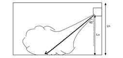
- the ceiling height Lh of a general house is 2.4 m
- the height Lo of the outlet 20b of the indoor unit 2 is 2.2 m
- the wind direction is 45 degrees.
- FIG. 29 is a diagram showing the effect of the wind speed on the floor surface temperature in the conventional heating start-up operation.
- FIG. 30 is a diagram showing the effect of the wind speed on the floor surface temperature in the heating activation operation according to the fourth embodiment.
- Even in the heating start-up operation as shown in FIG. 29, conventionally, the wind speed of the air blown out from the outlet 20d increases and collides with the floor surface.
- the air-conditioned air can heat the air-conditioned space without colliding with the floor surface.
- the air volume control unit 52 of the present embodiment controls the indoor fan 22 based on the wind speed of the air blown from the outlet 20b in the cooling start operation and the heating start operation. Specifically, the air volume control unit 52 sets the air volume at the time of starting the indoor fan 22 so that the air speed of the air blown from the outlet 20b becomes 3.0 m / s or less in the cooling start operation and the heating start operation. do. Since the wind speed of the air blown out from the air outlet 20d is obtained from the air volume of the indoor fan 22 and the opening area of the air outlet 20b, the air volume at startup is determined from the wind speed of 3.0 m / s and the opening area of the air outlet 20b. Desired.
- the conditioned air is made to collide with the floor surface by setting the starting air volume of the indoor fan 22 so that the wind speed of the air blown from the outlet 20d is 3.0 m / s or less. It is possible to cool or heat the space to be air-conditioned. As a result, further high efficiency can be realized.
- Embodiment 5 The air conditioner 100 according to the fifth embodiment will be described.
- the air conditioner 100 of the fifth embodiment is different from the first embodiment in the control of the indoor fan 22 in the air volume control unit 52.
- the differences from the first embodiment will be described, and the configuration and control of the other air conditioner 100 will be the same as those of the first embodiment.
- FIG. 31 is a control block diagram of the air conditioner 100 according to the fifth embodiment.
- the air conditioner 100 of the fifth embodiment further includes a window position sensor 36, a vertical wind direction plate 231 and a left and right wind direction plate 232.
- the window position sensor 36 is provided in the housing of the indoor unit 2, and the vertical wind direction plate 231 and the left and right wind direction plates 232 are provided in the air outlet 20b of the indoor unit 2.
- the window position sensor 36 is a sensor that detects the temperature of the air-conditioned space and detects the position of the window in the air-conditioned space based on the detection result. Further, the window position sensor 36 of the present embodiment detects the position of the window having high heat insulation specifications. Specifically, the window position sensor 36 acquires a thermal image of the air-conditioned space and detects the position of the window from the thermal image. For example, a portion having a temperature difference from the wall surface is detected as a window. Then, when the temperature of the window is close to the indoor air temperature Ta, the position of the detected window is transmitted to the control device 5, assuming that the window has a high heat insulation specification.
- the vertical wind direction plate 231 has the same configuration as the wind direction plate 23 of the first embodiment, and adjusts the wind direction in the vertical direction.
- the left and right wind direction plates 232 are rotatably provided on the axis of rotation parallel to the vertical direction at the outlet 20b, and adjust the blowing direction of the conditioned air in the left-right direction.
- the left-right wind direction plate 232 is composed of a plurality of plates arranged at intervals in the left-right direction of the air outlet 20b, and each of the plurality of plates is rotatable.
- the angle of the left-right wind direction plate 232 is changed by controlling a stepping motor (not shown) attached to the rotating shaft by the control device 5.
- the plurality of left and right wind direction plates 232 may be adjusted to have the same angle, or each of the plurality of plates may be adjusted to have a different angle.
- the wind direction control unit 53 of the present embodiment controls the angle of the left and right wind direction plates 232 so that the air-conditioned air is blown to the window position when the window position is detected by the window position sensor 36 in the cooling start operation. .. Further, the wind direction control unit 53 sets the angle of the vertical wind direction plate 231 to an angle close to 90 degrees. This makes it possible to cool the air-conditioned space without cooling the skeleton.
- the wind direction control unit 53 controls the angle of the left and right wind direction plates 232 so that the air-conditioned air is blown to the position of the window when the position of the window is detected by the window position sensor 36 in the heating start operation. Further, the wind direction control unit 53 sets the angle of the vertical wind direction plate 231 to an angle close to 90 degrees. This makes it possible to heat the air in the air-conditioned space without heating the skeleton.
- the air volume control unit 52 of the present embodiment may increase the air volume of the indoor fan 22 when the position of the window is detected by the window position sensor 36 in the cooling start operation and the heating start operation.
- the wind direction is changed so that the blown air is directed to the position of the window.
- the room temperature can reach the set temperature at an early stage. This improves efficiency at startup and improves comfort.
- the air conditioning device 100 may further include a person detecting means for detecting the presence or absence of a resident in the air-conditioned space.
- the human detection means is an infrared sensor that acquires a thermal image, a camera that acquires an image, or the like.
- the control device 5 may raise the temperature of the blown air when there is no occupant in the air-conditioned space. This makes it possible to raise the evaporation temperature and improve the efficiency of the air conditioner 100.
- the control device 5 may lower the temperature of the blown air when there is no occupant in the air-conditioned space. This makes it possible to raise the condensation temperature and improve the efficiency of the air conditioner 100.
- the wind direction control unit 53 may set the angle of the wind direction plate 23 according to the presence or absence of a resident in the air-conditioned space during the cooling start operation and the heating start operation.
- the air conditioner 100 may start the cooling start operation or the heating start operation before the scheduled use of the air-conditioned space.
- the timing of starting the cooling start operation or the heating start operation is determined based on the GPS information of the occupants or the schedule information.
- the wall temperature sensor 34, the distance measuring sensor 35, and the window position sensor 36 in the above embodiment are not limited to those provided in the indoor unit 2, and may be provided separately from the indoor unit 2.
- the control device 5 has a communication function with an external device, receives the detection results of the wall temperature sensor 34, the distance measuring sensor 35, and the window position sensor 36, and performs the cooling start operation and the heating start operation. ..
Abstract
This air conditioning device comprises: a heat exchanger that exchanges heat between air and a refrigerant; a fan that blows air heated or cooled by the heat exchanger into a space to be air-conditioned; a wind direction plate that changes the angle of the air blown into the space to be air-conditioned; and a control device that controls the air volume from the fan and the angle of the wind direction plate. The control device sets, at the start-up of cooling, the angle of the wind direction plate to an angle greater than 45 degrees when the vertical direction is 0 degrees, sets, at the start-up of heating, the angle of the wind direction plate to an angle less than 45 degrees when the vertical direction is 0 degrees, and sets, at the start-up of cooling and the start-up of heating, the air volume from the fan to a start-up air volume which is smaller than the maximum air volume.
Description
本開示は、居住空間などの空間の温度を調整する空気調和装置に関するものである。
This disclosure relates to an air conditioner that regulates the temperature of a space such as a living space.
従来、空気調和置の起動時に、迅速に部屋を冷房または暖房するために、空気調和装置の風向または風量を調節することが知られている。例えば、特許文献1には、暖房運転の起動時に、風向を斜め下方、送風量を最大とし、対流暖房を実施して室内温度を一定温度以上に上昇させる空気調和装置が開示されている。
Conventionally, it has been known to adjust the wind direction or volume of an air conditioner in order to quickly cool or heat a room when the air conditioner is activated. For example, Patent Document 1 discloses an air conditioner that raises the room temperature to a certain temperature or higher by performing convection heating with the wind direction diagonally downward and the maximum amount of air blown when the heating operation is started.
従来の空気調和装置では、起動時に、空調対象空間の空気と、壁および床面などの躯体とを含めた全ての熱負荷に対して、迅速に空調することを目的としている。しかしながら、空気調和装置の起動時に、躯体を含めた全ての熱負荷に対応した熱量を供給しようとすると、必要な空調能力が大きくなり、消費電力の増加を招いてしまう。
The purpose of the conventional air conditioner is to quickly air-condition the air in the air-conditioned space and all the heat loads including the frame such as the wall and floor at the time of starting. However, if an attempt is made to supply a heat amount corresponding to all heat loads including the skeleton at the time of starting the air conditioner, the required air conditioning capacity becomes large, which leads to an increase in power consumption.
また、近年の住宅は、高断熱および高気密化が進んでおり、空調対象空間の壁を通じて発生する熱貫流の割合は大きく低下している。そのため、空調対象空間内における温度差は従来に比べて発生しづらくなっており、温度差の発生を前提とした従来の空調制御については、改善の余地があった。
In recent years, housing has become highly insulated and airtight, and the proportion of thermal transmission generated through the walls of the air-conditioned space has dropped significantly. Therefore, the temperature difference in the air-conditioned space is less likely to occur than in the past, and there is room for improvement in the conventional air-conditioning control premised on the occurrence of the temperature difference.
本開示は、上記のような課題を解決するためのものであり、起動時における快適性を維持しつつ効率を向上させることができる空気調和装置を提供することを目的とする。
The present disclosure is for solving the above-mentioned problems, and an object of the present disclosure is to provide an air conditioner capable of improving efficiency while maintaining comfort at startup.
本開示に係る空気調和装置は、空気と冷媒とを熱交換する熱交換器と、熱交換器により加熱または冷却された空気を空調対象空間に吹出すファンと、空調対象空間へ吹出される空気の角度を変える風向板と、ファンの風量および風向板の角度を制御する制御装置と、を備え、制御装置は、冷房起動時に、風向板の角度を、鉛直方向を0度とした場合に45度より大きい角度に設定し、暖房起動時に、風向板の角度を、鉛直方向を0度とした場合に45度より小さい角度に設定し、冷房起動時および暖房起動時に、ファンの風量を最大風量よりも小さい起動時風量に設定するものである。
The air conditioner according to the present disclosure includes a heat exchanger that exchanges heat between air and a refrigerant, a fan that blows air heated or cooled by the heat exchanger into the air-conditioned space, and air blown into the air-conditioned space. It is equipped with a wind direction plate that changes the angle of the air conditioner and a control device that controls the air volume of the fan and the angle of the wind direction plate. Set the angle to be larger than the degree, set the angle of the wind direction plate to an angle smaller than 45 degrees when the vertical direction is 0 degree at the start of heating, and set the air volume of the fan to the maximum air volume at the start of cooling and the start of heating. It is set to a smaller start-up air volume.
本開示の空気調和装置によれば、起動時に空調対象空間の空気を優先して冷房または暖房することができ、起動時の快適性を維持しつつ、効率の向上を実現することが可能となる。
According to the air conditioner of the present disclosure, it is possible to preferentially cool or heat the air in the air-conditioned space at the time of starting, and it is possible to improve the efficiency while maintaining the comfort at the time of starting. ..
以下、図面を参照して、本開示の実施の形態について説明する。なお、各図中、同一又は相当する部分には、同一符号を付して、その説明を適宜省略又は簡略化する。また、各図に記載の構成について、その形状、大きさおよび配置等は、本開示の範囲内で適宜変更することができる。
Hereinafter, embodiments of the present disclosure will be described with reference to the drawings. In each figure, the same or corresponding parts are designated by the same reference numerals, and the description thereof will be omitted or simplified as appropriate. In addition, the shape, size, arrangement, etc. of the configurations shown in each figure can be appropriately changed within the scope of the present disclosure.
実施の形態1.
(空気調和装置の構成)
図1は、実施の形態1に係る空気調和装置100の概略構成図である。図1に示すように、実施の形態1の空気調和装置100は、空調対象空間の外に配置される室外機1と、空調対象空間内に配置される室内機2とからなる。室外機1と室内機2とは、配管、電源または信号線等の配線によって接続されている。室外機1は、圧縮機11と、流路切替弁12と、室外熱交換器13と、膨張弁14と、室外ファン15と、を備えている。室内機2は、室内熱交換器21と、室内ファン22と、風向板23と、第1温度センサ31と、第2温度センサ32と、室内温度センサ33と、壁温度センサ34と、制御装置5と、を備えている。Embodiment 1.
(Configuration of air conditioner)
FIG. 1 is a schematic configuration diagram of anair conditioner 100 according to the first embodiment. As shown in FIG. 1, the air conditioner 100 of the first embodiment includes an outdoor unit 1 arranged outside the air-conditioned space and an indoor unit 2 arranged inside the air-conditioned space. The outdoor unit 1 and the indoor unit 2 are connected by wiring such as piping, a power supply, or a signal line. The outdoor unit 1 includes a compressor 11, a flow path switching valve 12, an outdoor heat exchanger 13, an expansion valve 14, and an outdoor fan 15. The indoor unit 2 includes an indoor heat exchanger 21, an indoor fan 22, a wind direction plate 23, a first temperature sensor 31, a second temperature sensor 32, an indoor temperature sensor 33, a wall temperature sensor 34, and a control device. It is equipped with 5.
(空気調和装置の構成)
図1は、実施の形態1に係る空気調和装置100の概略構成図である。図1に示すように、実施の形態1の空気調和装置100は、空調対象空間の外に配置される室外機1と、空調対象空間内に配置される室内機2とからなる。室外機1と室内機2とは、配管、電源または信号線等の配線によって接続されている。室外機1は、圧縮機11と、流路切替弁12と、室外熱交換器13と、膨張弁14と、室外ファン15と、を備えている。室内機2は、室内熱交換器21と、室内ファン22と、風向板23と、第1温度センサ31と、第2温度センサ32と、室内温度センサ33と、壁温度センサ34と、制御装置5と、を備えている。
(Configuration of air conditioner)
FIG. 1 is a schematic configuration diagram of an
圧縮機11、流路切替弁12、室外熱交換器13、膨張弁14、および室内熱交換器21は、配管により接続され、冷媒回路を構成する。空気調和装置100の冷媒回路に循環する冷媒は、例えば二酸化炭素、炭化水素またはヘリウム等の自然冷媒、HFC410AまたはHFC407C等の塩素を含まない冷媒、もしくはR22またはR134a等のフロン系冷媒である。
The compressor 11, the flow path switching valve 12, the outdoor heat exchanger 13, the expansion valve 14, and the indoor heat exchanger 21 are connected by pipes to form a refrigerant circuit. The refrigerant circulating in the refrigerant circuit of the air conditioner 100 is, for example, a natural refrigerant such as carbon dioxide, hydrocarbon or helium, a chlorine-free refrigerant such as HFC410A or HFC407C, or a fluorocarbon-based refrigerant such as R22 or R134a.
圧縮機11は、低圧のガス冷媒を吸入して圧縮し、高圧のガス冷媒として吐出する流体機械である。圧縮機11としては、例えばレシプロ、ロータリー、スクロールまたはスクリューなどの各種タイプの圧縮機が用いられる。圧縮機11の運転周波数は、制御装置5によって制御される。
The compressor 11 is a fluid machine that sucks in a low-pressure gas refrigerant, compresses it, and discharges it as a high-pressure gas refrigerant. As the compressor 11, various types of compressors such as reciprocating engines, rotary engines, scrolls, and screws are used. The operating frequency of the compressor 11 is controlled by the control device 5.
流路切替弁12は、室外熱交換器13が凝縮器として機能する冷房運転と、室外熱交換器13が蒸発器として機能する暖房運転とを切替える四方弁である。流路切替弁12は、冷房運転時は図1に実線で示されるように、圧縮機11から吐出される冷媒が室外熱交換器13に流入するよう切替えられる。流路切替弁12は、暖房運転時は図1に破線で示されるように、圧縮機11から吐出される冷媒が室内熱交換器21に流入するよう切替えられる。
The flow path switching valve 12 is a four-way valve that switches between a cooling operation in which the outdoor heat exchanger 13 functions as a condenser and a heating operation in which the outdoor heat exchanger 13 functions as an evaporator. The flow path switching valve 12 is switched so that the refrigerant discharged from the compressor 11 flows into the outdoor heat exchanger 13 during the cooling operation, as shown by the solid line in FIG. The flow path switching valve 12 is switched so that the refrigerant discharged from the compressor 11 flows into the indoor heat exchanger 21 during the heating operation, as shown by the broken line in FIG.
室外熱交換器13は、例えばプレートフィンチューブ式の熱交換器であり、円管または扁平管の内部を流通する冷媒と、室外ファン15により供給される空気との熱交換を行う。室外熱交換器13は、流路切替弁12と、膨張弁14との間に配置される。室外熱交換器13は、暖房運転時には蒸発器として機能し、冷房運転時には凝縮器として機能する。
The outdoor heat exchanger 13 is, for example, a plate fin tube type heat exchanger that exchanges heat between the refrigerant flowing inside the circular tube or the flat tube and the air supplied by the outdoor fan 15. The outdoor heat exchanger 13 is arranged between the flow path switching valve 12 and the expansion valve 14. The outdoor heat exchanger 13 functions as an evaporator during the heating operation and as a condenser during the cooling operation.
膨張弁14は、冷媒を減圧させる弁である。膨張弁14は、制御装置5によって開度を調整可能な電子膨張弁である。膨張弁14は、室外熱交換器13と、室内熱交換器21との間に配置される。なお、図1において、膨張弁14は室外機1に配置されているが、室内機2に配置されてもよい。
The expansion valve 14 is a valve that reduces the pressure of the refrigerant. The expansion valve 14 is an electronic expansion valve whose opening degree can be adjusted by the control device 5. The expansion valve 14 is arranged between the outdoor heat exchanger 13 and the indoor heat exchanger 21. Although the expansion valve 14 is arranged in the outdoor unit 1 in FIG. 1, it may be arranged in the indoor unit 2.
室外ファン15は、空調対象空間外の空気を吸込み、室外熱交換器13を通過させて空調対象空間外に吹出す。室外ファン15は、例えばモータによって駆動されるプロペラファン、シロッコファンまたはクロスフローファンである。室外ファン15の風量は、制御装置5によって室外ファン15の回転数が制御されることにより制御される。室外ファン15のモータがDCモータの場合、制御装置5は、電流値を変化させて回転数を制御することで、室外ファン15の風量を制御する。また、室外ファン15のモータがACモータの場合、制御装置5は、インバータ制御により電源周波数を変化させて回転数を制御することで、室外ファン15の風量を制御する。
The outdoor fan 15 sucks in the air outside the air-conditioned space, passes it through the outdoor heat exchanger 13, and blows it out of the air-conditioned space. The outdoor fan 15 is, for example, a propeller fan, a sirocco fan, or a cross-flow fan driven by a motor. The air volume of the outdoor fan 15 is controlled by controlling the rotation speed of the outdoor fan 15 by the control device 5. When the motor of the outdoor fan 15 is a DC motor, the control device 5 controls the air volume of the outdoor fan 15 by controlling the rotation speed by changing the current value. When the motor of the outdoor fan 15 is an AC motor, the control device 5 controls the air volume of the outdoor fan 15 by controlling the rotation speed by changing the power supply frequency by inverter control.
室内熱交換器21は、例えばプレートフィンチューブ式の熱交換器であり、円管または扁平管の内部を流通する冷媒と、室内ファン22により送風される空気との熱交換を行う。室内熱交換器21は、膨張弁14と、流路切替弁12との間に配置される。室内熱交換器21は、暖房運転時には凝縮器として機能し、冷房運転時には蒸発器として機能する。
The indoor heat exchanger 21 is, for example, a plate fin tube type heat exchanger, and exchanges heat between the refrigerant circulating inside the circular tube or the flat tube and the air blown by the indoor fan 22. The indoor heat exchanger 21 is arranged between the expansion valve 14 and the flow path switching valve 12. The indoor heat exchanger 21 functions as a condenser during the heating operation and as an evaporator during the cooling operation.
室内ファン22は、空調対象空間内の空気を吸込み、室内熱交換器21を通過させて空調対象空間内に吹出す。室内ファン22は、例えばモータによって駆動されるプロペラファン、シロッコファンまたはクロスフローファンである。室内ファン22の風量は、制御装置5によって室内ファン22の回転数が制御されることにより制御される。室内ファン22のモータがDCモータの場合、制御装置5は、電流値を変化させて回転数を制御することで、室内ファン22の風量を制御する。また、室内ファン22のモータがACモータの場合、制御装置5は、インバータ制御により電源周波数を変化させて回転数を制御することで、室内ファン22の風量を制御する。
The indoor fan 22 sucks in the air in the air-conditioned space, passes it through the indoor heat exchanger 21, and blows it out into the air-conditioned space. The indoor fan 22 is, for example, a propeller fan, a sirocco fan, or a cross-flow fan driven by a motor. The air volume of the indoor fan 22 is controlled by controlling the rotation speed of the indoor fan 22 by the control device 5. When the motor of the indoor fan 22 is a DC motor, the control device 5 controls the air volume of the indoor fan 22 by controlling the rotation speed by changing the current value. When the motor of the indoor fan 22 is an AC motor, the control device 5 controls the air volume of the indoor fan 22 by controlling the rotation speed by changing the power supply frequency by inverter control.
なお、図1では、1つの室内ファン22が、空気の流れにおいて室内熱交換器21の上流に配置されているが、目標の風量が得られるのであれば、室内ファン22の配置および数は図1の例に限定されない。例えば、室内ファン22は、室内熱交換器21の下流に配置されてもよいし、複数の室内ファン22が室内熱交換器21の上流と下流とにそれぞれ配置されてもよい。
In FIG. 1, one indoor fan 22 is arranged upstream of the indoor heat exchanger 21 in the air flow, but if the target air volume can be obtained, the arrangement and number of the indoor fans 22 are shown in FIG. It is not limited to the example of 1. For example, the indoor fan 22 may be arranged downstream of the indoor heat exchanger 21, or a plurality of indoor fans 22 may be arranged upstream and downstream of the indoor heat exchanger 21, respectively.
室内機2は、空調対象空間の壁に取り付けられる壁掛け式の室内機である。室内機2の筐体には、吸込口20aと吹出口20bとが設けられている。室内ファン22により、空調対象空間の空気が吸込口20aから吸込まれ、室内熱交換器21によって冷却または加熱されて、吹出口20bから空調対象空間に吹出される。
The indoor unit 2 is a wall-mounted indoor unit that can be attached to the wall of the air-conditioned space. The housing of the indoor unit 2 is provided with a suction port 20a and an outlet 20b. The air in the air-conditioned space is sucked by the indoor fan 22 from the suction port 20a, cooled or heated by the indoor heat exchanger 21, and blown out to the air-conditioned space from the air outlet 20b.
風向板23は、吹出口20bにおいて、水平方向と平行な回転軸に回動可能に設けられ、室内熱交換器21によって冷却または加熱された空調空気の吹出し方向を上下方向に調節する。なお、風向板23の角度は、室内機2が空調対象空間の壁に設置された状態において、鉛直方向を0度とした場合の角度である。
The wind direction plate 23 is rotatably provided on a rotation axis parallel to the horizontal direction at the outlet 20b, and adjusts the blowing direction of the conditioned air cooled or heated by the indoor heat exchanger 21 in the vertical direction. The angle of the wind direction plate 23 is an angle when the vertical direction is 0 degrees when the indoor unit 2 is installed on the wall of the air-conditioned space.
第1温度センサ31は、室内熱交換器21と膨張弁14とを接続する配管に設けられ、冷房運転時において、室内熱交換器21の入口側の冷媒の温度を検出する。第2温度センサ32は、室内熱交換器21と流路切替弁12とを接続する配管に設けられ、冷房運転時において、室内熱交換器21の出口側の冷媒の温度を検出する。第1温度センサ31および第2温度センサ32により検出された冷媒温度は、制御装置5に送信される。
The first temperature sensor 31 is provided in the pipe connecting the indoor heat exchanger 21 and the expansion valve 14, and detects the temperature of the refrigerant on the inlet side of the indoor heat exchanger 21 during the cooling operation. The second temperature sensor 32 is provided in the pipe connecting the indoor heat exchanger 21 and the flow path switching valve 12, and detects the temperature of the refrigerant on the outlet side of the indoor heat exchanger 21 during the cooling operation. The refrigerant temperature detected by the first temperature sensor 31 and the second temperature sensor 32 is transmitted to the control device 5.
室内温度センサ33は、吸込口20aの周囲に配置され、空調対象空間から室内機2に吸込まれる空気の温度を検出する。室内温度センサ33により検出された室内空気温度Taは、制御装置5に送信される。
The indoor temperature sensor 33 is arranged around the suction port 20a and detects the temperature of the air sucked into the indoor unit 2 from the air-conditioned space. The indoor air temperature Ta detected by the indoor temperature sensor 33 is transmitted to the control device 5.
壁温度センサ34は、室内機2の筐体に設けられ、空調対象空間の壁の温度を検出する。具体的には、壁温度センサ34は、室内機2と対向する壁であって、室内機2の空調空気の吹出し方向に位置する壁の温度を検出する。壁温度センサ34は、例えば対象物の温度を非接触で測定できるサーモパイルセンサなどの赤外線センサである。壁温度センサ34により検出された壁温度Twは、制御装置5へ送信される。
The wall temperature sensor 34 is provided in the housing of the indoor unit 2 and detects the temperature of the wall in the air-conditioned space. Specifically, the wall temperature sensor 34 detects the temperature of the wall facing the indoor unit 2 and located in the direction of blowing out the conditioned air of the indoor unit 2. The wall temperature sensor 34 is, for example, an infrared sensor such as a thermopile sensor that can measure the temperature of an object in a non-contact manner. The wall temperature Tw detected by the wall temperature sensor 34 is transmitted to the control device 5.
制御装置5は、CPU、ROM、RAM、およびI/Oポート等を備えたマイクロコンピュータである。制御装置5は、リモコン等を介して入力される使用者からの指示と、第1温度センサ31、第2温度センサ32、室内温度センサ33および壁温度センサ34の検出結果とに基づいて空気調和装置100全体の動作を制御する。なお、図1では、制御装置5が室内機2に設けられているが、室外機1に設けられてもよいし、室外機1および室内機2にそれぞれ個別の制御装置5を設け、互いに通信する構成としてもよい。
The control device 5 is a microcomputer equipped with a CPU, ROM, RAM, an I / O port, and the like. The control device 5 adjusts the air based on the instruction from the user input via the remote control or the like and the detection results of the first temperature sensor 31, the second temperature sensor 32, the indoor temperature sensor 33, and the wall temperature sensor 34. It controls the operation of the entire device 100. Although the control device 5 is provided in the indoor unit 2 in FIG. 1, it may be provided in the outdoor unit 1, or the outdoor unit 1 and the indoor unit 2 are provided with individual control devices 5 to communicate with each other. It may be configured to be used.
(空気調和装置の動作)
図2は、実施の形態1に係る空気調和装置100の制御ブロック図である。図2に示すように、空気調和装置100の制御装置5は、機能部として、運転制御部51と、風量制御部52と、風向制御部53とを有する。各機能部は、制御装置5がプログラムを実行することにより実現されるか、または専用の処理回路により実現される。 (Operation of air conditioner)
FIG. 2 is a control block diagram of theair conditioner 100 according to the first embodiment. As shown in FIG. 2, the control device 5 of the air conditioner 100 has an operation control unit 51, an air volume control unit 52, and a wind direction control unit 53 as functional units. Each functional unit is realized by the control device 5 executing a program, or is realized by a dedicated processing circuit.
図2は、実施の形態1に係る空気調和装置100の制御ブロック図である。図2に示すように、空気調和装置100の制御装置5は、機能部として、運転制御部51と、風量制御部52と、風向制御部53とを有する。各機能部は、制御装置5がプログラムを実行することにより実現されるか、または専用の処理回路により実現される。 (Operation of air conditioner)
FIG. 2 is a control block diagram of the
運転制御部51は、リモコン等を介して入力される設定情報と、第1温度センサ31、第2温度センサ32、室内温度センサ33および壁温度センサ34の検出結果とに基づき、冷房運転および暖房運転を実行する。入力される設定情報は、例えば冷房運転、暖房運転の設定、および設定温度Tnなどである。運転制御部51は、設定情報と各温度センサの検出結果に基づき、圧縮機11の運転周波数、流路切替弁12の切替え、膨張弁14の開度、および室外ファン15の回転数を制御する。
The operation control unit 51 performs cooling operation and heating based on the setting information input via the remote control or the like and the detection results of the first temperature sensor 31, the second temperature sensor 32, the room temperature sensor 33, and the wall temperature sensor 34. Perform driving. The input setting information is, for example, a cooling operation, a heating operation setting, and a set temperature Tn. The operation control unit 51 controls the operation frequency of the compressor 11, the switching of the flow path switching valve 12, the opening degree of the expansion valve 14, and the rotation speed of the outdoor fan 15 based on the setting information and the detection result of each temperature sensor. ..
風量制御部52は、リモコン等を介して入力される設定情報と、室内温度センサ33および壁温度センサ34により検出された温度と、に基づき、室内ファン22の風量を制御する。風向制御部53は、リモコン等を介して入力される設定情報に基づき風向板23の角度を制御する。
The air volume control unit 52 controls the air volume of the indoor fan 22 based on the setting information input via the remote controller or the like and the temperature detected by the indoor temperature sensor 33 and the wall temperature sensor 34. The wind direction control unit 53 controls the angle of the wind direction plate 23 based on the setting information input via the remote controller or the like.
(冷房運転)
空気調和装置100の冷房運転時の動作について説明する。冷房運転時においては、まず、圧縮機11で圧縮され、高温高圧の気体となった冷媒が凝縮器として機能する室外熱交換器13に流入する。冷媒は、室外熱交換器13にて高温高圧の気体から液体に相変化し、室外熱交換器13を通過する空気を加熱する。その後、冷媒は開度が小さく設定された膨張弁14にて減圧され、低温低圧の液体と気体が混在した二相状態になり、蒸発器として機能する室内熱交換器21に流入する。室内熱交換器21において、冷媒は、液体から気体に相変化し、室内熱交換器21を通過する空気を冷却する。その後、冷媒は圧縮機11に流入し、再度、高温高圧の気体となる。 (Cooling operation)
The operation of theair conditioner 100 during the cooling operation will be described. During the cooling operation, first, the refrigerant compressed by the compressor 11 and turned into a high-temperature and high-pressure gas flows into the outdoor heat exchanger 13 that functions as a condenser. The refrigerant undergoes a phase change from a high-temperature, high-pressure gas to a liquid in the outdoor heat exchanger 13, and heats the air passing through the outdoor heat exchanger 13. After that, the refrigerant is depressurized by the expansion valve 14 set to have a small opening degree, becomes a two-phase state in which a low-temperature low-pressure liquid and a gas are mixed, and flows into the indoor heat exchanger 21 functioning as an evaporator. In the indoor heat exchanger 21, the refrigerant phase changes from a liquid to a gas and cools the air passing through the indoor heat exchanger 21. After that, the refrigerant flows into the compressor 11 and becomes a high-temperature and high-pressure gas again.
空気調和装置100の冷房運転時の動作について説明する。冷房運転時においては、まず、圧縮機11で圧縮され、高温高圧の気体となった冷媒が凝縮器として機能する室外熱交換器13に流入する。冷媒は、室外熱交換器13にて高温高圧の気体から液体に相変化し、室外熱交換器13を通過する空気を加熱する。その後、冷媒は開度が小さく設定された膨張弁14にて減圧され、低温低圧の液体と気体が混在した二相状態になり、蒸発器として機能する室内熱交換器21に流入する。室内熱交換器21において、冷媒は、液体から気体に相変化し、室内熱交換器21を通過する空気を冷却する。その後、冷媒は圧縮機11に流入し、再度、高温高圧の気体となる。 (Cooling operation)
The operation of the
図3は、実施の形態1に係る室内機2の冷房運転時の動作を示す図である。冷房運転時には、制御装置5は、膨張弁14の開度を小さく設定する。これにより、室内熱交換器21に流入する冷媒の圧力は低下する。また、制御装置5は、第1温度センサ31によって検出される冷媒の入口温度と、第2温度センサ32によって検出される冷媒の出口温度との差から演算される過熱度が所定の値となるように、膨張弁14の開度を制御する。図3に示されるように、空調対象空間内の空気(A1)は、室内ファン22により、蒸発器として機能する室内熱交換器21へ供給される。室内熱交換器21は通過する空気を冷却する。その後、冷却された空調空気(B1)が、空調対象空間内に供給される。
FIG. 3 is a diagram showing the operation of the indoor unit 2 according to the first embodiment during the cooling operation. During the cooling operation, the control device 5 sets the opening degree of the expansion valve 14 to be small. As a result, the pressure of the refrigerant flowing into the indoor heat exchanger 21 decreases. Further, in the control device 5, the degree of superheat calculated from the difference between the inlet temperature of the refrigerant detected by the first temperature sensor 31 and the outlet temperature of the refrigerant detected by the second temperature sensor 32 becomes a predetermined value. As described above, the opening degree of the expansion valve 14 is controlled. As shown in FIG. 3, the air (A1) in the air-conditioned space is supplied by the indoor fan 22 to the indoor heat exchanger 21 that functions as an evaporator. The indoor heat exchanger 21 cools the passing air. After that, the cooled conditioned air (B1) is supplied into the conditioned space.
図4は、実施の形態1に係る室内機2の冷房運転時の空気の状態変化を示す湿り空気線図である。図4の横軸は温度(℃)を表し、縦軸は絶対湿度(kg/kg´)を表している。図4中の点A1および点B1は、図3中の(A1)および(B1)の位置にそれぞれ対応している。図4に示すように、室内熱交換器21を通過した空気(A1)は、冷媒との熱交換により冷却除湿され、低温かつ相対湿度の高い状態となった後、絶対湿度が低下した状態(B1)となって、空調対象空間に給気として供給される。
FIG. 4 is a psychrometric chart showing a change in the state of air during the cooling operation of the indoor unit 2 according to the first embodiment. The horizontal axis of FIG. 4 represents temperature (° C.), and the vertical axis represents absolute humidity (kg / kg'). Points A1 and B1 in FIG. 4 correspond to the positions (A1) and (B1) in FIG. 3, respectively. As shown in FIG. 4, the air (A1) that has passed through the indoor heat exchanger 21 is cooled and dehumidified by heat exchange with the refrigerant, and is in a low temperature and high relative humidity state, and then in a state in which the absolute humidity is lowered (A). It becomes B1) and is supplied as air supply to the air-conditioned space.
(暖房運転)
空気調和装置100の暖房運転時の動作について説明する。暖房運転時においては、圧縮機11で圧縮され、高温高圧の気体となった冷媒が凝縮器として機能する室内熱交換器21に流入する。冷媒は、室内熱交換器21にて高温高圧の気体から液体に相変化し、室内熱交換器21を通過する空気を加熱する。その後、冷媒は開度を小さく設定された膨張弁14にて減圧され、低温低圧の液体と気体が混在した二相状態になり、蒸発器として機能する室外熱交換器13に流入する。室外熱交換器13において、冷媒は、液体から気体に相変化し、室外熱交換器13を通過する空気を冷却する。その後、冷媒は圧縮機11に流入し、再度、高温高圧の気体となる。 (Heating operation)
The operation of theair conditioner 100 during the heating operation will be described. During the heating operation, the refrigerant compressed by the compressor 11 and turned into a high-temperature and high-pressure gas flows into the indoor heat exchanger 21 that functions as a condenser. The refrigerant undergoes a phase change from a high-temperature, high-pressure gas to a liquid in the indoor heat exchanger 21, and heats the air passing through the indoor heat exchanger 21. After that, the refrigerant is depressurized by the expansion valve 14 whose opening degree is set small, becomes a two-phase state in which a low-temperature low-pressure liquid and a gas are mixed, and flows into the outdoor heat exchanger 13 functioning as an evaporator. In the outdoor heat exchanger 13, the refrigerant changes phase from a liquid to a gas and cools the air passing through the outdoor heat exchanger 13. After that, the refrigerant flows into the compressor 11 and becomes a high-temperature and high-pressure gas again.
空気調和装置100の暖房運転時の動作について説明する。暖房運転時においては、圧縮機11で圧縮され、高温高圧の気体となった冷媒が凝縮器として機能する室内熱交換器21に流入する。冷媒は、室内熱交換器21にて高温高圧の気体から液体に相変化し、室内熱交換器21を通過する空気を加熱する。その後、冷媒は開度を小さく設定された膨張弁14にて減圧され、低温低圧の液体と気体が混在した二相状態になり、蒸発器として機能する室外熱交換器13に流入する。室外熱交換器13において、冷媒は、液体から気体に相変化し、室外熱交換器13を通過する空気を冷却する。その後、冷媒は圧縮機11に流入し、再度、高温高圧の気体となる。 (Heating operation)
The operation of the
図5は、実施の形態1に係る室内機2の暖房運転時の動作を示す図である。暖房運転時には、制御装置5は、膨張弁14の開度を小さく設定する。これにより、室外熱交換器13に流入する冷媒の圧力は低下する。また、制御装置5は、第2温度センサ32によって検出される冷媒の出口温度と、冷媒の凝縮温度との差から演算される過冷却度が所定の値となるように、膨張弁14の開度を制御する。図5に示されるように、空調対象内の空気(A2)は、室内ファン22により、凝縮器として機能する室内熱交換器21へ供給される。室内熱交換器21は通過する空気を加熱する。その後、加熱された空調空気(B2)が、空調対象空間に供給される。
FIG. 5 is a diagram showing the operation of the indoor unit 2 according to the first embodiment during the heating operation. During the heating operation, the control device 5 sets the opening degree of the expansion valve 14 to be small. As a result, the pressure of the refrigerant flowing into the outdoor heat exchanger 13 decreases. Further, the control device 5 opens the expansion valve 14 so that the supercooling degree calculated from the difference between the outlet temperature of the refrigerant detected by the second temperature sensor 32 and the condensation temperature of the refrigerant becomes a predetermined value. Control the degree. As shown in FIG. 5, the air (A2) in the air-conditioned object is supplied to the indoor heat exchanger 21 functioning as a condenser by the indoor fan 22. The indoor heat exchanger 21 heats the passing air. After that, the heated conditioned air (B2) is supplied to the conditioned space.
図6は、実施の形態1に係る室内機2の暖房運転時の空気の状態変化を示す湿り空気線図である。図6の横軸は温度(℃)を表し、縦軸は絶対湿度(kg/kg´)を表している。図6中の点A2および点B2は、図5中の(A2)および(B2)の位置にそれぞれ対応している。図6に示すように、室内熱交換器21を通過した空気(A2)は、冷媒との熱交換により加熱され高温の状態(B2)となって、空調対象空間に給気として供給される。
FIG. 6 is a psychrometric chart showing a change in the air state during the heating operation of the indoor unit 2 according to the first embodiment. The horizontal axis of FIG. 6 represents temperature (° C.), and the vertical axis represents absolute humidity (kg / kg'). Points A2 and B2 in FIG. 6 correspond to the positions (A2) and (B2) in FIG. 5, respectively. As shown in FIG. 6, the air (A2) that has passed through the indoor heat exchanger 21 is heated by heat exchange with the refrigerant, becomes a high temperature state (B2), and is supplied to the air-conditioned space as supply air.
(冷房起動運転)
本実施の形態における冷房起動運転について説明する。従来、冷房運転の起動時には、空調対象空間に対して高効率且つ高容量の運転状態を実現し、室内温度を設定温度に早期に到達させるよう、空調空気の風量と風向とが制御されていた。例えば、冷房運転の起動時において、室内温度と設定温度との差が大きい場合は、室内ファン22の風量が室温安定時と比較して大きく設定され、空調空気の風向は、部屋の中心または45度に設定されていた。 (Cooling start operation)
The cooling start-up operation in the present embodiment will be described. Conventionally, when the cooling operation is started, the air volume and direction of the air-conditioned air are controlled so as to realize a highly efficient and high-capacity operating state for the air-conditioned space and to reach the set temperature at an early stage. .. For example, when the difference between the room temperature and the set temperature is large at the start of the cooling operation, the air volume of theroom fan 22 is set to be larger than that when the room temperature is stable, and the wind direction of the conditioned air is the center of the room or 45. It was set every time.
本実施の形態における冷房起動運転について説明する。従来、冷房運転の起動時には、空調対象空間に対して高効率且つ高容量の運転状態を実現し、室内温度を設定温度に早期に到達させるよう、空調空気の風量と風向とが制御されていた。例えば、冷房運転の起動時において、室内温度と設定温度との差が大きい場合は、室内ファン22の風量が室温安定時と比較して大きく設定され、空調空気の風向は、部屋の中心または45度に設定されていた。 (Cooling start operation)
The cooling start-up operation in the present embodiment will be described. Conventionally, when the cooling operation is started, the air volume and direction of the air-conditioned air are controlled so as to realize a highly efficient and high-capacity operating state for the air-conditioned space and to reach the set temperature at an early stage. .. For example, when the difference between the room temperature and the set temperature is large at the start of the cooling operation, the air volume of the
図7は、冷房時における従来の住宅への熱負荷を示す図であり、図8は、冷房時における近年の住宅への熱負荷を示す図である。図7および図8の矢印は熱負荷を示し、矢印の大きさは熱負荷の大きさを示している。図7および図8に示すように、住宅に係る熱負荷としては、室外との温度差から発生する貫流熱負荷Laと、隙間風による換気負荷Lbと、機械換気による熱負荷Lcと、日射による熱負荷Ldとがある。図8に示すように、近年では、住宅の断熱性能が向上した結果、貫流熱負荷Laが従来に比べて減少する。また、住宅の気密性能が向上した結果、換気負荷Lbが従来に比べて減少する。すなわち、近年では、冷房時における熱負荷としては、機械換気による熱負荷Lcと、日射による熱負荷Ldとが主要因となり、壁面からの熱負荷である貫流熱負荷Laおよび換気負荷Lbは大きく減少している。
FIG. 7 is a diagram showing a heat load on a conventional house during cooling, and FIG. 8 is a diagram showing a heat load on a recent house during cooling. The arrows in FIGS. 7 and 8 indicate the heat load, and the size of the arrow indicates the magnitude of the heat load. As shown in FIGS. 7 and 8, the heat load related to the house includes a once-through heat load La generated from a temperature difference from the outside, a ventilation load Lb due to draft, a heat load Lc due to mechanical ventilation, and solar radiation. There is a heat load Ld. As shown in FIG. 8, in recent years, as a result of improving the heat insulating performance of a house, the once-through heat load La is reduced as compared with the conventional case. Further, as a result of improving the airtightness of the house, the ventilation load Lb is reduced as compared with the conventional case. That is, in recent years, as the heat load during cooling, the heat load Lc due to mechanical ventilation and the heat load Ld due to solar radiation are the main factors, and the heat load La and the ventilation load Lb, which are heat loads from the wall surface, are greatly reduced. is doing.
従来の断熱性能または気密性能の低い住宅では、壁面からの熱負荷を冷却する必要がある。加えて、貫流熱負荷Laの特性から、外気温度と室内温度との差が大きいほど熱負荷が大きくなる。そのため、従来では、風量を大きくして壁および床面などの躯体を含めた空調対象空間を冷却することで、室温を目標温度に到達させていた。一方、断熱性能または気密性能の高い住宅では、壁面からの熱負荷が従来と比べて小さくなり、外気温度と室内温度との差が大きくなっても熱負荷が大きく変化しない。そこで、本実施の形態の空気調和装置100では、冷房運転の起動時において、空調対象空間の空気温度を優先して冷房する冷房起動運転を行う。
In a conventional house with low heat insulation performance or airtightness, it is necessary to cool the heat load from the wall surface. In addition, from the characteristics of the once-through heat load La, the larger the difference between the outside air temperature and the room temperature, the larger the heat load. Therefore, in the past, the room temperature was reached to the target temperature by increasing the air volume and cooling the air-conditioned space including the skeleton such as the wall and the floor. On the other hand, in a house having high heat insulation performance or airtightness, the heat load from the wall surface is smaller than before, and the heat load does not change significantly even if the difference between the outside air temperature and the room temperature becomes large. Therefore, in the air conditioner 100 of the present embodiment, at the time of starting the cooling operation, the cooling start operation of giving priority to the air temperature of the air-conditioned space is performed.
図9は、従来の冷房起動運転における室内ファンの風量の変化を示す図である。図10は、実施の形態1に係る冷房起動運転における室内ファン22の風量の変化を示す図である。図9および図10の横軸は時間、縦軸は室内ファン22の風量を示している。なお、「冷房起動運転」とは、冷房運転の開始から室内空気温度Taが設定温度Tnに到達するまでの間の運転をいうものとする。図9に示すように、従来の冷房起動運転では、冷房運転開始時t0には、室内ファンの風量が最大風量とされ、設定温度Tnに到達した時間tnに、室内ファンの風量が減少される。
FIG. 9 is a diagram showing changes in the air volume of the indoor fan in the conventional cooling start operation. FIG. 10 is a diagram showing changes in the air volume of the indoor fan 22 in the cooling start-up operation according to the first embodiment. The horizontal axis of FIGS. 9 and 10 shows time, and the vertical axis shows the air volume of the indoor fan 22. The "cooling start operation" is defined as an operation from the start of the cooling operation to the time when the indoor air temperature Ta reaches the set temperature Tn. As shown in FIG. 9, in the conventional cooling start operation, the air volume of the indoor fan is set to the maximum air volume at t0 at the start of the cooling operation, and the air volume of the indoor fan is reduced at the time tun when the set temperature Tn is reached. ..
一方、図10に示すように、本実施の形態の冷房起動運転では、風量制御部52は、冷房運転開始時t0において、室内ファン22の風量を起動時風量に設定する。起動時風量は、空調対象空間の空気の温度のみを低下させるために設定される風量であり、吹出口20bから吹出される空気が、壁または床に直接当たらないような風量に設定される。具体的には、起動時風量は、室内ファン22のモータの回転数の下限値による風量以上であって、且つ室内ファン22の最大風量よりも小さい風量である。起動時風量は、例えば吹出口20bから吹出される空気の到達距離が、室内機2に対向する壁面までの距離以下となる風量である。到達距離は、例えば、吹出口20bから、吹出された空気の速度が0.25m/sとなる場所までの距離である。図10の例では、起動時風量は、最大風量の80%に設定される。起動時風量は、起動時の室内空気温度Taと設定温度Tnとの差によらず、一定の値であってもよいし、起動時の室内空気温度Taと設定温度Tnとの差に応じて異なる風量が設定されてもよい。ただし、何れの場合においても、起動時風量は、室内ファン22の最大風量よりも小さい風量とする。
On the other hand, as shown in FIG. 10, in the cooling start operation of the present embodiment, the air volume control unit 52 sets the air volume of the indoor fan 22 to the start air volume at t0 at the start of the cooling operation. The start-up air volume is an air volume set to lower only the temperature of the air in the air-conditioned space, and is set so that the air blown out from the outlet 20b does not directly hit the wall or the floor. Specifically, the air volume at startup is equal to or greater than the air volume according to the lower limit of the rotation speed of the motor of the indoor fan 22, and is smaller than the maximum air volume of the indoor fan 22. The start-up air volume is, for example, an air volume at which the reach of the air blown from the outlet 20b is equal to or less than the distance to the wall surface facing the indoor unit 2. The reachable distance is, for example, the distance from the outlet 20b to a place where the velocity of the blown air is 0.25 m / s. In the example of FIG. 10, the starting air volume is set to 80% of the maximum air volume. The start-up air volume may be a constant value regardless of the difference between the start-up indoor air temperature Ta and the set temperature Tn, or may be a constant value depending on the difference between the start-up indoor air temperature Ta and the set temperature Tn. Different air volumes may be set. However, in any case, the air volume at startup is set to be smaller than the maximum air volume of the indoor fan 22.
このように室内ファン22の風量を制御することで、吹出口20bから吹出される空気の到達距離を短くすることができ、空調対象空間内の空気温度を選択的に低下させることが可能となる。これにより、室内空気温度Taを設定温度Tnまで低下させるために壁および床などの躯体を冷却する必要がなくなるため、必要な空調能力を低減させることができる。その結果、冷房運転の起動時における消費電力の低減が可能になるとともに、従来と比べて同等または早期に空調対象空間の空気を冷却することができる。
By controlling the air volume of the indoor fan 22 in this way, the reach of the air blown out from the outlet 20b can be shortened, and the air temperature in the air-conditioned space can be selectively lowered. .. As a result, it is not necessary to cool the skeleton such as the wall and the floor in order to lower the indoor air temperature Ta to the set temperature Tn, so that the required air conditioning capacity can be reduced. As a result, it is possible to reduce the power consumption at the start of the cooling operation, and it is possible to cool the air in the air-conditioned space at the same time or earlier than in the conventional case.
また、風量制御部52は、室内温度センサ33により検出される室内空気温度Taが設定温度Tnに近づくと、室内ファン22の風量を増加させる。室内ファン22の風量を設定温度Tnに近づくにしたがって増加させ、壁および床面などの躯体を徐々に冷却することで、空気調和装置100の冷凍サイクルの効率を向上させることができ、快適性と省エネ性とが向上する。
Further, the air volume control unit 52 increases the air volume of the indoor fan 22 when the indoor air temperature Ta detected by the indoor temperature sensor 33 approaches the set temperature Tn. By increasing the air volume of the indoor fan 22 as it approaches the set temperature Tn and gradually cooling the skeleton such as the wall and floor, the efficiency of the refrigeration cycle of the air conditioner 100 can be improved, and the comfort and comfort can be improved. Energy saving is improved.
風量制御部52は、時間tnに到達すると、すなわち、室内温度センサ33により検出される室内空気温度Taが設定温度Tnに到達すると、室内ファン22の風量を最大風量に設定する。上記のように、本実施の形態の空気調和装置100は、起動運転時において、空調対象空間の空気を優先的に冷却しているため、室内空気温度Taが設定温度Tnに到達した後に、躯体からの発熱に対する処理を行う。ここでは、風量制御部52は、壁温度センサ34により検出される壁温度Twが室内空気温度Taと同等となるまで、室内ファン22の風量を最大風量とする。これにより、空調対象空間の躯体を含めた全体が冷却される。これにより、室温安定時において、躯体からの放射熱の影響が軽減され、快適性が向上する。
The air volume control unit 52 sets the air volume of the indoor fan 22 to the maximum air volume when the time tun is reached, that is, when the indoor air temperature Ta detected by the indoor temperature sensor 33 reaches the set temperature Tn. As described above, since the air conditioner 100 of the present embodiment preferentially cools the air in the air-conditioned space during the start-up operation, the skeleton after the indoor air temperature Ta reaches the set temperature Tn. Process against heat generation from. Here, the air volume control unit 52 sets the air volume of the indoor fan 22 as the maximum air volume until the wall temperature Tw detected by the wall temperature sensor 34 becomes equal to the indoor air temperature Ta. As a result, the entire space including the skeleton of the air-conditioned space is cooled. As a result, when the room temperature is stable, the influence of radiant heat from the skeleton is reduced and the comfort is improved.
図11は、従来の冷房起動運転による室内空気温度Taおよび壁温度Twの変化を示す図である。図12は、実施の形態1に係る冷房起動運転による室内空気温度Taおよび壁温度Twの変化を示す図である。図11および図12の横軸は時間、縦軸は温度を示している。図11に示すように、従来の冷房起動運転では、空調対象空間の空気と躯体とが冷却対象とされることで、室内空気温度Taと壁温度Twとが同じように下がっていく。一方、図12に示すように、本実施の形態の冷房起動運転によると、空調対象空間の空気のみを冷却対象とすることで、まず室内空気温度Taが設定温度Tnまで下がり、その後、壁温度Twが下がる。
FIG. 11 is a diagram showing changes in the indoor air temperature Ta and the wall temperature Tw due to the conventional cooling start operation. FIG. 12 is a diagram showing changes in the indoor air temperature Ta and the wall temperature Tw due to the cooling start-up operation according to the first embodiment. The horizontal axis of FIGS. 11 and 12 indicates time, and the vertical axis indicates temperature. As shown in FIG. 11, in the conventional cooling start-up operation, the air in the air-conditioned space and the skeleton are targeted for cooling, so that the indoor air temperature Ta and the wall temperature Tw are similarly lowered. On the other hand, as shown in FIG. 12, according to the cooling start operation of the present embodiment, by targeting only the air in the air-conditioned space as the cooling target, the indoor air temperature Ta first drops to the set temperature Tn, and then the wall temperature. Tw goes down.
図13は、従来の冷房起動運転による空気調和装置の消費電力の変化を示す図である。図14は、実施の形態1に係る冷房起動運転による空気調和装置100の消費電力の変化を示す図である。図13および図14の横軸は時間、縦軸は空気調和装置100の消費電力を示している。図13に示すように、従来の冷房起動運転では、室内ファンが最大風量で駆動されるため、冷房運転開始時t0から設定温度Tnに到達した時間tnまでの消費電力が高くなる。一方、図14に示すように、本実施の形態の冷房起動運転では、室内ファン22の風量が最大風量より小さい起動時風量に設定されるため、冷房運転開始時t0から設定温度Tnに到達した時間tnまでの消費電力を従来例に比べて低くすることができる。
FIG. 13 is a diagram showing changes in the power consumption of the air conditioner due to the conventional cooling start operation. FIG. 14 is a diagram showing a change in power consumption of the air conditioner 100 due to the cooling start operation according to the first embodiment. The horizontal axis of FIGS. 13 and 14 shows time, and the vertical axis shows the power consumption of the air conditioner 100. As shown in FIG. 13, in the conventional cooling start operation, since the indoor fan is driven by the maximum air volume, the power consumption from t0 at the start of the cooling operation to the time tun when the set temperature Tn is reached is high. On the other hand, as shown in FIG. 14, in the cooling start operation of the present embodiment, the air volume of the indoor fan 22 is set to the start air volume smaller than the maximum air volume, so that the set temperature Tn is reached from t0 at the start of the cooling operation. The power consumption up to the time tun can be made lower than that of the conventional example.
上記のように、風量制御部52の制御により、冷房運転の起動時における室内ファン22の風量が小さくなることにより、吹出口20bから吹出される空気の風速は低くなる。そのため、本実施の形態の冷房起動運転時には、従来の冷房起動運転時と比較すると、密度差による空調空気の上下移動の影響が大きくなる。冷房運転時に吹出口20bから吹出される空気の温度は空調対象空間の空気温度よりも低い。そのため、冷房運転時に吹出口20bから吹出される空気の密度が周囲に比べて高くなり、下降方向に風向が変化する。そこで、風向制御部53は、冷房起動運転において、空調空気の吹出し方向が、鉛直方向を0度とした場合、45度よりも大きくなるよう、風向板23の角度θを設定する。具体的には、風向板23の角度θを、鉛直方向を0度とした場合、45度よりも大きくなるよう設定する。
As described above, the air volume of the indoor fan 22 at the start of the cooling operation is reduced by the control of the air volume control unit 52, so that the wind speed of the air blown out from the outlet 20b is lowered. Therefore, at the time of the cooling start operation of the present embodiment, the influence of the vertical movement of the conditioned air due to the density difference becomes larger than that at the time of the conventional cooling start operation. The temperature of the air blown out from the outlet 20b during the cooling operation is lower than the air temperature of the air-conditioned space. Therefore, the density of the air blown out from the outlet 20b during the cooling operation becomes higher than that of the surroundings, and the wind direction changes in the downward direction. Therefore, the wind direction control unit 53 sets the angle θ of the wind direction plate 23 so that the blowing direction of the conditioned air becomes larger than 45 degrees when the vertical direction is 0 degree in the cooling start operation. Specifically, the angle θ of the wind direction plate 23 is set to be larger than 45 degrees when the vertical direction is 0 degrees.
これにより、冷房起動運転において、空調対象空間の全体に空調空気を循環させることができる。なお、風向制御部53は、風向板23の角度θを45度から90度(水平方向)の間の何れかの角度に設定すればよい。これにより、冷気が天井面を冷却せず、且つ空調空気を効率よく空調対象空間内に拡散させることができる。また、風向板23の角度θを45度よりも大きく設定するほど、室内ファン22の起動時風量を大きく設定することで、空調対象空間に効率よく冷気を供給することが可能となる。
This makes it possible to circulate the conditioned air throughout the air-conditioned space in the cooling start-up operation. The wind direction control unit 53 may set the angle θ of the wind direction plate 23 to any angle between 45 degrees and 90 degrees (horizontal direction). As a result, the cold air does not cool the ceiling surface, and the conditioned air can be efficiently diffused into the conditioned space. Further, as the angle θ of the wind direction plate 23 is set to be larger than 45 degrees, the air volume at the time of starting the indoor fan 22 is set to be large, so that cold air can be efficiently supplied to the air-conditioned space.
図15は、従来の冷房起動運転による風向および風量の影響を示す図である。図16は、実施の形態1に係る冷房起動運転による風向および風量の影響を示す図である。図15および図16は、室内機2が設置された空調対象空間を側方から見た図である。図15に示すように、従来の冷房起動運転の場合、室内ファンの風量が最大風量となることで、吹出口から吹出される空気が壁および床に直接当たり、躯体を含む空調対象空間全体が冷却される。一方、図16に示すように、本実施の形態の冷房起動運転では、室内ファン22の風量が最大風量よりも小さく設定され、風向板23の角度θが45度よりも大きく設定される。これにより、吹出口20bから吹出される空気が壁に当たることなく空調対象空間内に循環され、空調対象空間内の空気を優先して冷却することができる。
FIG. 15 is a diagram showing the influence of the wind direction and the air volume due to the conventional cooling start operation. FIG. 16 is a diagram showing the effects of the wind direction and the air volume due to the cooling start-up operation according to the first embodiment. 15 and 16 are views of the air-conditioned space in which the indoor unit 2 is installed, as viewed from the side. As shown in FIG. 15, in the case of the conventional cooling start operation, the air volume of the indoor fan becomes the maximum air volume, so that the air blown out from the air outlet directly hits the wall and the floor, and the entire air-conditioned space including the skeleton is covered. It will be cooled. On the other hand, as shown in FIG. 16, in the cooling start operation of the present embodiment, the air volume of the indoor fan 22 is set to be smaller than the maximum air volume, and the angle θ of the wind direction plate 23 is set to be larger than 45 degrees. As a result, the air blown out from the outlet 20b is circulated in the air-conditioned space without hitting the wall, and the air in the air-conditioned space can be preferentially cooled.
図17は、実施の形態1に係る空気調和装置100の冷房起動運転のフローチャートである。図17のフローチャートは、冷房運転の開始が指示されることにより、制御装置5によって実行される。冷房起動運転では、まず、風向制御部53により、風向板23の角度θが45度より大きく設定される(S11)。
FIG. 17 is a flowchart of the cooling start operation of the air conditioner 100 according to the first embodiment. The flowchart of FIG. 17 is executed by the control device 5 when the start of the cooling operation is instructed. In the cooling start operation, first, the angle θ of the wind direction plate 23 is set to be larger than 45 degrees by the wind direction control unit 53 (S11).
そして、風量制御部52により、室内ファン22の風量が、起動時風量に設定される(S12)。起動時風量は、室内ファン22の最大風量よりも小さい風量である。そして、風量制御部52により、室内温度センサ33により検出された室内空気温度Taが、設定温度Tnに近づいたか否かが判断される。具体的には、室内空気温度Taと設定温度Tnとの差が閾値α以下となったか否かが判断される(S13)。αは、予め設定された閾値であり、例えば2℃である。
Then, the air volume of the indoor fan 22 is set to the air volume at startup by the air volume control unit 52 (S12). The air volume at startup is smaller than the maximum air volume of the indoor fan 22. Then, the air volume control unit 52 determines whether or not the indoor air temperature Ta detected by the indoor temperature sensor 33 has approached the set temperature Tn. Specifically, it is determined whether or not the difference between the indoor air temperature Ta and the set temperature Tn is equal to or less than the threshold value α (S13). α is a preset threshold value, for example, 2 ° C.
そして、室内空気温度Taと設定温度Tnとの差が閾値αより大きい場合は(S13:NO)、起動時風量での冷房運転が継続される。一方、室内空気温度Taと設定温度Tnとの差が閾値α以下となった場合(S13:YES)、室内ファン22の風量が起動時風量から増加される(S14)。
Then, when the difference between the indoor air temperature Ta and the set temperature Tn is larger than the threshold value α (S13: NO), the cooling operation at the start-up air volume is continued. On the other hand, when the difference between the indoor air temperature Ta and the set temperature Tn is equal to or less than the threshold value α (S13: YES), the air volume of the indoor fan 22 is increased from the starting air volume (S14).
そして、風量制御部52により、室内温度センサ33により検出された室内空気温度Taが、設定温度Tn以下となったか否かが判断される(S15)。室内空気温度Taが、設定温度Tnより高い場合(S15:NO)、風量を増加させながら冷房運転が継続される。一方、室内空気温度Taが、設定温度Tn以下となった場合(S15:YES)、室内ファン22の風量が最大風量に設定される(S16)。
Then, the air volume control unit 52 determines whether or not the indoor air temperature Ta detected by the indoor temperature sensor 33 is equal to or lower than the set temperature Tn (S15). When the indoor air temperature Ta is higher than the set temperature Tn (S15: NO), the cooling operation is continued while increasing the air volume. On the other hand, when the indoor air temperature Ta becomes equal to or less than the set temperature Tn (S15: YES), the air volume of the indoor fan 22 is set to the maximum air volume (S16).
そして、風量制御部52により、壁温度センサ34により検出された壁温度Twが、室内空気温度Ta以下となったか否かが判断される(S17)。壁温度Twが、室内空気温度Taより高い場合(S17:NO)、最大風量での冷房運転が継続される。一方、壁温度Twが、室内空気温度Ta以下となった場合(S17:YES)、通常制御が実施される(S18)。通常制御では、室内ファン22の風量が最大風量から低減され、室内空気温度Taおよび壁温度Twが設定温度Tnを維持するためのフィードバック制御が実施される。
Then, the air volume control unit 52 determines whether or not the wall temperature Tw detected by the wall temperature sensor 34 is equal to or lower than the indoor air temperature Ta (S17). When the wall temperature Tw is higher than the indoor air temperature Ta (S17: NO), the cooling operation at the maximum air volume is continued. On the other hand, when the wall temperature Tw becomes equal to or lower than the indoor air temperature Ta (S17: YES), normal control is performed (S18). In the normal control, the air volume of the indoor fan 22 is reduced from the maximum air volume, and feedback control is performed for the indoor air temperature Ta and the wall temperature Tw to maintain the set temperature Tn.
(暖房起動運転)
次に、本実施の形態における暖房起動運転について説明する。従来、暖房運転の起動時には、冷房運転の起動時と同様に、空調対象空間に対して高効率且つ高容量の運転状態を実現し、室内温度を設定温度に早期に到達させるよう、空調空気の風量と風向とが制御されていた。例えば、暖房運転の起動時において、室内温度と設定温度との差が大きい場合は、室内ファン22の風量が室温安定時と比較して大きく設定され、空調空気の風向は、部屋の中心に設定されていた。さらに暖房運転では、吹出される空調空気の温度が、体温以下である場合は、使用者にドラフト感が発生するため、快適性維持を目的として空調空気の温度を上昇させる必要があり、凝縮温度を高くするため、効率悪化が発生していた。 (Heating start operation)
Next, the heating activation operation in the present embodiment will be described. Conventionally, when the heating operation is started, the air-conditioned air is used so as to realize a highly efficient and high-capacity operating state for the air-conditioned space and to reach the set temperature at an early stage, as in the case of the cooling operation. The air volume and direction were controlled. For example, when the difference between the room temperature and the set temperature is large at the start of the heating operation, the air volume of theroom fan 22 is set larger than that when the room temperature is stable, and the wind direction of the conditioned air is set at the center of the room. It had been. Furthermore, in the heating operation, if the temperature of the conditioned air blown out is lower than the body temperature, a draft feeling is generated for the user, so it is necessary to raise the temperature of the conditioned air for the purpose of maintaining comfort, and the condensation temperature. In order to increase the temperature, the efficiency deteriorated.
次に、本実施の形態における暖房起動運転について説明する。従来、暖房運転の起動時には、冷房運転の起動時と同様に、空調対象空間に対して高効率且つ高容量の運転状態を実現し、室内温度を設定温度に早期に到達させるよう、空調空気の風量と風向とが制御されていた。例えば、暖房運転の起動時において、室内温度と設定温度との差が大きい場合は、室内ファン22の風量が室温安定時と比較して大きく設定され、空調空気の風向は、部屋の中心に設定されていた。さらに暖房運転では、吹出される空調空気の温度が、体温以下である場合は、使用者にドラフト感が発生するため、快適性維持を目的として空調空気の温度を上昇させる必要があり、凝縮温度を高くするため、効率悪化が発生していた。 (Heating start operation)
Next, the heating activation operation in the present embodiment will be described. Conventionally, when the heating operation is started, the air-conditioned air is used so as to realize a highly efficient and high-capacity operating state for the air-conditioned space and to reach the set temperature at an early stage, as in the case of the cooling operation. The air volume and direction were controlled. For example, when the difference between the room temperature and the set temperature is large at the start of the heating operation, the air volume of the
図18は、暖房時における従来の住宅への熱負荷を示す図であり、図19は、暖房時における近年の住宅への熱負荷を示す図である。図18および図19の矢印は熱負荷を示し、矢印の大きさは熱負荷の大きさを示している。図18および図19に示すように、住宅に係る熱負荷としては、室外との温度差から発生する貫流熱負荷Laと、隙間風による換気負荷Lbと、機械換気による熱負荷Lcとがある。図19に示すように、近年では、住宅の断熱性能が向上した結果、貫流熱負荷Laが、従来に比べて減少する。また、住宅の気密性能が向上した結果、換気負荷Lbが、従来に比べて減少する。すなわち、近年では、暖房時における熱負荷としては、機械換気による熱負荷Lcが主要因となり、壁面からの熱負荷である貫流熱負荷Laおよび換気負荷Lbとは大きく減少している。なお、日射は加熱源となるため、暖房時は負荷として機能しない。そのため、冷房時と比較すると、暖房負荷の総量は大きく低減する結果となる。
FIG. 18 is a diagram showing a heat load on a conventional house during heating, and FIG. 19 is a diagram showing a heat load on a house in recent years during heating. The arrows in FIGS. 18 and 19 indicate the heat load, and the size of the arrow indicates the magnitude of the heat load. As shown in FIGS. 18 and 19, the heat load related to the house includes a once-through heat load La generated from a temperature difference from the outside, a ventilation load Lb due to draft, and a heat load Lc due to mechanical ventilation. As shown in FIG. 19, in recent years, as a result of improving the heat insulating performance of a house, the once-through heat load La is reduced as compared with the conventional case. Further, as a result of improving the airtightness of the house, the ventilation load Lb is reduced as compared with the conventional case. That is, in recent years, as the heat load during heating, the heat load Lc due to mechanical ventilation is the main factor, and the once-through heat load La and the ventilation load Lb, which are the heat loads from the wall surface, are greatly reduced. Since solar radiation is a heating source, it does not function as a load during heating. Therefore, the total amount of the heating load is greatly reduced as compared with the case of cooling.
従来の断熱性能または気密性能の低い住宅では、壁面から熱が漏洩するために、壁面を加熱する必要がある。加えて、貫流熱負荷Laの特性とから、外気温度と室内温度との差が大きいほど熱負荷が大きくなる。そのため、従来では、風量を大きくして躯体を含めた空調対象空間を加熱することで、室温を目標温度に到達させていた。一方、断熱性能または気密性能の高い住宅では、従来と比べて壁面からの熱漏洩は少なく、室内温度と室外温度の差が大きくなっても壁面付近の空気温度が低下しにくい。そこで、本実施の形態の空気調和装置100では、暖房運転の起動時においても、空調対象空間の空気温度を優先して暖房する暖房起動運転を行う。
In a conventional house with low heat insulation performance or airtightness, it is necessary to heat the wall surface because heat leaks from the wall surface. In addition, from the characteristics of the once-through heat load La, the larger the difference between the outside air temperature and the room temperature, the larger the heat load. Therefore, in the past, the room temperature was reached to the target temperature by increasing the air volume and heating the air-conditioned space including the skeleton. On the other hand, in a house having high heat insulation performance or airtightness, heat leakage from the wall surface is smaller than in the conventional case, and even if the difference between the indoor temperature and the outdoor temperature becomes large, the air temperature near the wall surface is unlikely to decrease. Therefore, in the air conditioning device 100 of the present embodiment, even when the heating operation is started, the heating start operation for heating by giving priority to the air temperature of the air-conditioned space is performed.
具体的には、風量制御部52は、冷房起動運転時と同様に、起動時における室内ファン22の風量を図10に示すように制御する。具体的には、風量制御部52は、暖房運転開始時t0において、室内ファン22の風量を起動時風量に設定する。起動時風量は、冷房起動運転における起動時風量と同様に、空調対象空間の空気の温度のみを低下させるために設定される風量であり、吹出口20bから吹出される空気が、壁または床に直接当たらないような風量に設定される。具体的には、起動時風量は、室内ファン22のモータの回転数の下限値による風量以上であって、且つ室内ファン22の最大風量よりも小さい風量である。暖房運転時の起動時風量は、冷房起動運転時の起動時風量と同じ風量であってもよいし、異なる風量としてもよい。
Specifically, the air volume control unit 52 controls the air volume of the indoor fan 22 at the time of starting, as shown in FIG. 10, as in the case of the cooling start operation. Specifically, the air volume control unit 52 sets the air volume of the indoor fan 22 to the air volume at startup at t0 at the start of heating operation. The start-up air volume is an air volume set to lower only the temperature of the air in the air-conditioned space, similar to the start-up air volume in the cooling start-up operation, and the air blown from the outlet 20b is sent to the wall or the floor. The air volume is set so that it does not hit directly. Specifically, the air volume at startup is equal to or greater than the air volume according to the lower limit of the rotation speed of the motor of the indoor fan 22, and is smaller than the maximum air volume of the indoor fan 22. The start-up air volume during the heating operation may be the same as the start-up air volume during the cooling start-up operation, or may be a different air volume.
このように室内ファン22の風量を制御することで、吹出口20bから吹出される空気の到達距離を短くすることができ、空調対象空間内の空気温度を選択的に上昇させることが可能となる。これにより、室内空気温度Taを設定温度Tnまで上昇させるために壁および床などの躯体を加熱する必要がなくなるため、必要な空調能力を低減させることができる。その結果、暖房運転の起動時における消費電力の低減が可能になるとともに、従来と比べて同等または早期に空調対象空間の空気を加熱することができる。
By controlling the air volume of the indoor fan 22 in this way, the reach of the air blown out from the outlet 20b can be shortened, and the air temperature in the air-conditioned space can be selectively raised. .. As a result, it is not necessary to heat the skeleton such as the wall and the floor in order to raise the indoor air temperature Ta to the set temperature Tn, so that the required air conditioning capacity can be reduced. As a result, it is possible to reduce the power consumption at the start of the heating operation, and it is possible to heat the air in the air-conditioned space at the same time or earlier than in the conventional case.
また、風量制御部52は、室内温度センサ33により検出される室内空気温度Taが設定温度Tnに近づくと、室内ファン22の風量を増加させる。室内ファン22の風量を設定温度Tnに近づくにしたがって増加させることで、壁および床面などの躯体を徐々に加熱することで、空気調和装置100の効率を向上させることができ、快適性と省エネ性とが向上する。
Further, the air volume control unit 52 increases the air volume of the indoor fan 22 when the indoor air temperature Ta detected by the indoor temperature sensor 33 approaches the set temperature Tn. By increasing the air volume of the indoor fan 22 as it approaches the set temperature Tn, the efficiency of the air conditioner 100 can be improved by gradually heating the skeleton such as walls and floors, and comfort and energy saving can be achieved. Improves sex.
風量制御部52は、時間tnに到達すると、すなわち、室内温度センサ33により検出される室内空気温度Taが設定温度Tnに到達すると、室内ファン22の風量を最大風量に設定する。ここでは、風量制御部52は、壁温度センサ34により検出される壁温度Twが室内空気温度Taと同等となるまで、室内ファン22の風量を最大風量とする。これにより、空調対象空間の躯体を含めた全体が加熱される。これにより、室温安定時において、躯体からの熱漏洩の影響が軽減され、快適性が向上する。
The air volume control unit 52 sets the air volume of the indoor fan 22 to the maximum air volume when the time tun is reached, that is, when the indoor air temperature Ta detected by the indoor temperature sensor 33 reaches the set temperature Tn. Here, the air volume control unit 52 sets the air volume of the indoor fan 22 as the maximum air volume until the wall temperature Tw detected by the wall temperature sensor 34 becomes equal to the indoor air temperature Ta. As a result, the entire space including the skeleton of the air-conditioned space is heated. As a result, when the room temperature is stable, the influence of heat leakage from the skeleton is reduced and the comfort is improved.
図20は、従来の暖房起動運転による室内空気温度Taおよび壁温度Twの変化を示す図である。図21は、実施の形態1に係る暖房起動運転による室内空気温度Taおよび壁温度Twの変化を示す図である。図20および図21の横軸は時間、縦軸は温度を示している。図20に示すように、従来の暖房起動運転では、空調対象空間の空気と躯体とが加熱対象とされることで、室内空気温度Taと壁温度Twとが同じように上昇する。一方、図21に示すように、本実施の形態の暖房起動運転によると、空調対象空間の空気のみを加熱対象とすることで、まず室内空気温度Taが設定温度Tnまで上昇し、その後、壁温度Twが上昇する。
FIG. 20 is a diagram showing changes in the indoor air temperature Ta and the wall temperature Tw due to the conventional heating start-up operation. FIG. 21 is a diagram showing changes in the indoor air temperature Ta and the wall temperature Tw due to the heating activation operation according to the first embodiment. The horizontal axis of FIGS. 20 and 21 indicates time, and the vertical axis indicates temperature. As shown in FIG. 20, in the conventional heating start-up operation, the indoor air temperature Ta and the wall temperature Tw rise in the same manner because the air in the air-conditioned space and the skeleton are targeted for heating. On the other hand, as shown in FIG. 21, according to the heating activation operation of the present embodiment, by targeting only the air in the air-conditioned space as the heating target, the indoor air temperature Ta first rises to the set temperature Tn, and then the wall. The temperature Tw rises.
なお、従来の暖房起動運転による空気調和装置の消費電力の変化は、図13と同じであり、実施の形態1に係る暖房起動運転による空気調和装置100の消費電力の変化は図14と同じである。本実施の形態の暖房起動運転では、暖房運転開始時t0から設定温度Tnに到達した時間tnまでの消費電力を従来例に比べて低くすることができる。
The change in the power consumption of the air conditioner due to the conventional heating start operation is the same as in FIG. 13, and the change in the power consumption of the air conditioner 100 due to the heating start operation according to the first embodiment is the same as in FIG. be. In the heating start-up operation of the present embodiment, the power consumption from t0 at the start of the heating operation to the time tn when the set temperature Tn is reached can be reduced as compared with the conventional example.
上記のように、風量制御部52の制御により、暖房起動時における室内ファン22の風量が小さくなることにより、吹出口20bから吹出される空調空気の風速は低くなる。そのため、本実施の形態の暖房起動運転時には、従来の暖房起動運転時と比較すると、密度差による空調空気の上下移動の影響が大きくなる。暖房運転時に吹出口20bから吹出される空気の温度は空調対象空間の空気温度よりも高い。そのため暖房運転時に吹出口20bから吹出される空気の密度が周囲に比べて低くなり、上昇方向に風向が変化する。そこで、風向制御部53は、暖房起動運転において、空調空気の吹出し方向が、鉛直方向を0度とした場合、45度よりも小さくなるよう、風向板23の角度θを設定する。具体的には、風向板23の角度θを、鉛直方向を0度とした場合、45度よりも小さくなるよう設定する。
As described above, the air volume of the indoor fan 22 at the time of starting heating is reduced by the control of the air volume control unit 52, so that the wind speed of the conditioned air blown out from the outlet 20b is lowered. Therefore, in the heating start operation of the present embodiment, the influence of the vertical movement of the conditioned air due to the density difference becomes larger than that in the conventional heating start operation. The temperature of the air blown out from the outlet 20b during the heating operation is higher than the air temperature of the air-conditioned space. Therefore, the density of the air blown out from the outlet 20b during the heating operation is lower than that of the surroundings, and the wind direction changes in the ascending direction. Therefore, the wind direction control unit 53 sets the angle θ of the wind direction plate 23 so that the blowing direction of the conditioned air is smaller than 45 degrees when the vertical direction is 0 degree in the heating start operation. Specifically, the angle θ of the wind direction plate 23 is set to be smaller than 45 degrees when the vertical direction is 0 degrees.
これにより、暖房起動運転において、空調対象空間の全体に空調空気を循環させることができる。なお、風向制御部53は、風向板23の角度θを0度(鉛直方向)から45度の間の何れかの角度に設定すればよい。これにより、暖気が天井面に滞留せず、且つ空調空気を効率よく空調対象空間内に拡散させることができる。
This makes it possible to circulate the conditioned air throughout the air-conditioned space in the heating start-up operation. The wind direction control unit 53 may set the angle θ of the wind direction plate 23 to any angle between 0 degree (vertical direction) and 45 degrees. As a result, warm air does not stay on the ceiling surface, and the conditioned air can be efficiently diffused in the conditioned space.
なお、暖房の場合は、快適性維持の目的で、空調空気の温度が高くなる場合が多いため、空調空気温度と周囲空気温度との差が、冷房の場合と比較すると大きくなる傾向がある。そのため、暖房起動運転において、風向板23の角度θを45度に近い角度に設定することで、冷房の場合と比較して空調対象空間内を効率よく暖房することが可能となる。さらに、風向板23の角度θを45度に近い角度に設定することで、床面近傍での対流を抑制することができ、床下空間への熱量供給量が低下するため、室温の上昇を加速させることも可能となる。また、風向板23の角度を45度よりも小さく設定するほど、室内ファン22の起動時風量を小さく設定することで、空調対象空間に効率よく暖気を供給することが可能となる。
In the case of heating, the temperature of the conditioned air is often high for the purpose of maintaining comfort, so the difference between the conditioned air temperature and the ambient air temperature tends to be larger than in the case of cooling. Therefore, by setting the angle θ of the wind direction plate 23 to an angle close to 45 degrees in the heating start operation, it is possible to efficiently heat the air-conditioned space as compared with the case of cooling. Furthermore, by setting the angle θ of the wind direction plate 23 to an angle close to 45 degrees, convection near the floor surface can be suppressed, and the amount of heat supplied to the underfloor space decreases, thus accelerating the rise in room temperature. It is also possible to make it. Further, as the angle of the wind direction plate 23 is set smaller than 45 degrees, the air volume at the time of starting the indoor fan 22 is set smaller, so that warm air can be efficiently supplied to the air-conditioned space.
図22は、実施の形態1に係る暖房起動運転による風向および風量の影響を示す図である。図22に示すように、本実施の形態の暖房起動運転では、室内ファン22の風量が最大風量よりも小さく設定され、風向板23の角度θが45度よりも小さく設定されることで、吹出口20bから吹出される空気が壁に当たることなく空調対象空間内に循環される。これにより、空調対象空間内の空気を優先して冷却することができる。
FIG. 22 is a diagram showing the influence of the wind direction and the air volume due to the heating activation operation according to the first embodiment. As shown in FIG. 22, in the heating activation operation of the present embodiment, the air volume of the indoor fan 22 is set to be smaller than the maximum air volume, and the angle θ of the wind direction plate 23 is set to be smaller than 45 degrees. The air blown out from the outlet 20b is circulated in the air-conditioned space without hitting the wall. As a result, the air in the air-conditioned space can be preferentially cooled.
図23は、実施の形態1に係る空気調和装置100の暖房起動運転のフローチャートである。図23のフローチャートは、暖房運転の開始が指示されることにより、制御装置5によって実行される。暖房起動運転では、まず、風向制御部53により、風向板23の角度θが45度より小さく設定される(S21)。
FIG. 23 is a flowchart of the heating start operation of the air conditioner 100 according to the first embodiment. The flowchart of FIG. 23 is executed by the control device 5 when the start of the heating operation is instructed. In the heating start operation, first, the angle θ of the wind direction plate 23 is set to be smaller than 45 degrees by the wind direction control unit 53 (S21).
そして、風量制御部52により、室内ファン22の風量が、起動時風量に設定される(S22)。起動時風量は、室内ファン22の最大風量よりも小さい風量である。そして、風量制御部52により、室内温度センサ33により検出された室内空気温度Taが、設定温度Tnに近づいたか否かが判断される。具体的には、設定温度Tnと室内空気温度Taとの差が閾値α以下となったか否かが判断される(S23)。αは、予め設定された閾値であり、例えば2℃である。
Then, the air volume of the indoor fan 22 is set to the air volume at startup by the air volume control unit 52 (S22). The air volume at startup is smaller than the maximum air volume of the indoor fan 22. Then, the air volume control unit 52 determines whether or not the indoor air temperature Ta detected by the indoor temperature sensor 33 has approached the set temperature Tn. Specifically, it is determined whether or not the difference between the set temperature Tn and the indoor air temperature Ta is equal to or less than the threshold value α (S23). α is a preset threshold value, for example, 2 ° C.
そして、設定温度Tnと室内空気温度Taとの差が閾値αより大きい場合は(S23:NO)、起動時風量での暖房が継続される。一方、設定温度Tnと室内空気温度Taとの差が閾値α以下となった場合(S23:YES)、室内ファン22の風量が起動時風量から増加される(S24)。
Then, when the difference between the set temperature Tn and the indoor air temperature Ta is larger than the threshold value α (S23: NO), heating with the starting air volume is continued. On the other hand, when the difference between the set temperature Tn and the indoor air temperature Ta is equal to or less than the threshold value α (S23: YES), the air volume of the indoor fan 22 is increased from the starting air volume (S24).
そして、風量制御部52により、室内温度センサ33により検出された室内空気温度Taが、設定温度Tn以上となったか否かが判断される(S25)。室内空気温度Taが、設定温度Tn未満の場合(S25:NO)、風量を増加させながら暖房運転が継続される。一方、室内空気温度Taが、設定温度Tn以上となった場合(S25:YES)、室内ファン22の風量が最大風量に設定される(S26)。
Then, the air volume control unit 52 determines whether or not the indoor air temperature Ta detected by the indoor temperature sensor 33 is equal to or higher than the set temperature Tn (S25). When the indoor air temperature Ta is less than the set temperature Tn (S25: NO), the heating operation is continued while increasing the air volume. On the other hand, when the indoor air temperature Ta becomes equal to or higher than the set temperature Tn (S25: YES), the air volume of the indoor fan 22 is set to the maximum air volume (S26).
そして、風量制御部52により、壁温度センサ34により検出された壁温度Twが、室内空気温度Ta以上となったか否かが判断される(S27)。壁温度Twが、室内空気温度Ta未満の場合(S27:NO)、最大風量での暖房運転が継続される。一方、壁温度Twが、室内空気温度Ta以上となった場合(S27:YES)、通常の暖房制御が実施される(S28)。通常の暖房制御では、室内ファン22の風量が最大風量から低減され、室内空気温度Taおよび壁温度Twが設定温度Tnを維持するようフィードバック制御が実施される。
Then, the air volume control unit 52 determines whether or not the wall temperature Tw detected by the wall temperature sensor 34 is equal to or higher than the indoor air temperature Ta (S27). When the wall temperature Tw is less than the indoor air temperature Ta (S27: NO), the heating operation at the maximum air volume is continued. On the other hand, when the wall temperature Tw becomes equal to or higher than the indoor air temperature Ta (S27: YES), normal heating control is performed (S28). In normal heating control, the air volume of the indoor fan 22 is reduced from the maximum air volume, and feedback control is performed so that the indoor air temperature Ta and the wall temperature Tw maintain the set temperature Tn.
以上のように、本実施の形態の空気調和装置100では、冷房起動運転および暖房起動運転において、従来の空調対象空間の躯体と空気との両方を冷却または加熱する制御とは異なり、空調対象空間の空気を優先的に冷却または加熱する。これにより、空調対象空間の空気温度を設定温度まで冷却または加熱するのに必要な冷房能力または暖房能力が、従来の起動運転よりも少なくなるため、消費電力を低減させることができ、効率が向上する。また、空調対象空間の空気を優先的に冷却または加熱することで、空調対象空間の空気温度を設定温度まで冷却または加熱することができ、快適性を維持することができる。
As described above, in the air conditioning device 100 of the present embodiment, the air conditioning target space is different from the conventional control of cooling or heating both the skeleton and the air of the air conditioning target space in the cooling start operation and the heating start operation. Air is preferentially cooled or heated. As a result, the cooling capacity or heating capacity required to cool or heat the air temperature of the air-conditioned space to the set temperature is smaller than that of the conventional start-up operation, so that power consumption can be reduced and efficiency is improved. do. Further, by preferentially cooling or heating the air in the air-conditioned space, the air temperature in the air-conditioned space can be cooled or heated to a set temperature, and comfort can be maintained.
また、冷房起動運転および暖房起動運転において、空調空気の吹出し方向を制御することで、吹出される空調空気の浮力の影響を軽減し、空調対象空間全体を均一に空調することが可能となり、快適性が向上する。
In addition, by controlling the blowing direction of the air-conditioned air in the cooling start operation and the heating start operation, the influence of the buoyancy of the air-conditioned air blown out can be reduced, and the entire air-conditioned space can be uniformly air-conditioned, which is comfortable. Improves sex.
さらに、従来の運転と比較すると起動運転時に多くの空調能力を必要としないため、圧縮機11の周波数を起動時に大きくする必要がなく、負荷を平準化することができる。その結果、空調運転時間あたりの効率がさらに向上し、省電力化が可能となる。
Further, since a large amount of air conditioning capacity is not required at the start-up operation as compared with the conventional operation, it is not necessary to increase the frequency of the compressor 11 at the start-up operation, and the load can be leveled. As a result, the efficiency per air-conditioning operation time is further improved, and power saving becomes possible.
また、本実施の形態では、起動時に躯体に空調空気が接触することを避けること主眼としており、吹出口20bだけでなく、吸込口20aの周辺の空気もなるべく壁面と接触しない方がよい。これに対し、室内ファン22の起動時風量を最大風量よりも小さく設定することで、吸込口20aから吸込まれる空気から、壁面近傍の風速を低減することが可能となり、さらに空調対象空間の空気を優先して空調することができる。
Further, in the present embodiment, the main purpose is to prevent the conditioned air from coming into contact with the skeleton at the time of starting, and it is better that not only the air outlet 20b but also the air around the suction port 20a does not come into contact with the wall surface as much as possible. On the other hand, by setting the start-up air volume of the indoor fan 22 to be smaller than the maximum air volume, it is possible to reduce the wind speed near the wall surface from the air sucked from the suction port 20a, and further, the air in the air-conditioned space. Can be prioritized for air conditioning.
実施の形態2.
実施の形態2に係る空気調和装置100について説明する。実施の形態2の空気調和装置100は、風向制御部53における風向板23の制御において、実施の形態1と相違する。以下では、実施の形態1との相違について説明し、それ以外の空気調和装置100の構成および制御については、実施の形態1と同じとする。Embodiment 2.
Theair conditioner 100 according to the second embodiment will be described. The air conditioner 100 of the second embodiment is different from the first embodiment in the control of the wind direction plate 23 by the wind direction control unit 53. Hereinafter, the differences from the first embodiment will be described, and the configuration and control of the other air conditioner 100 will be the same as those of the first embodiment.
実施の形態2に係る空気調和装置100について説明する。実施の形態2の空気調和装置100は、風向制御部53における風向板23の制御において、実施の形態1と相違する。以下では、実施の形態1との相違について説明し、それ以外の空気調和装置100の構成および制御については、実施の形態1と同じとする。
The
図24は、実施の形態2に係る空気調和装置100の制御ブロック図である。図24に示すように、実施の形態2の空気調和装置100は、空調対象空間を画定する壁およびと室内機2との距離を測定する測距センサ35をさらに備える。また、空気調和装置100の制御装置5は、測距センサ35により測定された距離に基づいて、起動運転時における風向板23の角度(以下、「起動時角度」という)を算出する角度算出部54をさらに有する。
FIG. 24 is a control block diagram of the air conditioner 100 according to the second embodiment. As shown in FIG. 24, the air conditioner 100 of the second embodiment further includes a distance measuring sensor 35 that measures the distance between the wall defining the air-conditioned space and the indoor unit 2. Further, the control device 5 of the air conditioner 100 is an angle calculation unit that calculates the angle of the wind direction plate 23 during the start-up operation (hereinafter referred to as “start-up angle”) based on the distance measured by the distance measurement sensor 35. Further has 54.
測距センサ35は、光位相式測距センサ、または超音波式測距センサである。測距センサ35は、室内機2の筐体に取り付けられ、室内機2と対向する壁面までの距離と、室内機2の設置高さとを測定する。測距センサ35によって測定された距離は、制御装置5に送信される。
The distance measuring sensor 35 is an optical phase type distance measuring sensor or an ultrasonic type distance measuring sensor. The distance measuring sensor 35 is attached to the housing of the indoor unit 2 and measures the distance to the wall surface facing the indoor unit 2 and the installation height of the indoor unit 2. The distance measured by the distance measuring sensor 35 is transmitted to the control device 5.
制御装置5の角度算出部54は、測距センサ35によって測定された壁面までの距離と設置高さとから、床面と、吹出口20bの位置から対向する壁面の下端をつなぐ線とがなす起動時角度θdを算出する。角度算出部54で算出された起動時角度θdは、風向制御部53に送信される。
The angle calculation unit 54 of the control device 5 is activated by a line connecting the floor surface and the lower end of the opposite wall surface from the position of the air outlet 20b based on the distance to the wall surface and the installation height measured by the distance measuring sensor 35. Calculate the hour angle θd. The start-up angle θd calculated by the angle calculation unit 54 is transmitted to the wind direction control unit 53.
風向制御部53は、冷房起動運転において、空調空気の吹出し方向が、鉛直方向を0度とした場合、起動時角度θdよりも大きくなるよう、風向板23の角度θを設定する。具体的には、風向板23の角度θを、鉛直方向を0度とした場合、起動時角度θdよりも大きく、且つ90度以下となるよう設定する。また、風向制御部53は、暖房起動運転において、空調空気の吹出し方向が、鉛直方向を0度とした場合、起動時角度θdよりも小さくなるよう、風向板23の角度θを設定する。具体的には、風向板23の角度を起動時角度θdより小さく、且つ0度以上となるよう設定する。
The wind direction control unit 53 sets the angle θ of the wind direction plate 23 so that the blowing direction of the air-conditioning air becomes larger than the starting angle θd when the vertical direction is 0 degree in the cooling start operation. Specifically, when the vertical direction is 0 degree, the angle θ of the wind direction plate 23 is set to be larger than the start-up angle θd and 90 degrees or less. Further, the wind direction control unit 53 sets the angle θ of the wind direction plate 23 so that the blowing direction of the conditioned air is smaller than the starting angle θd when the vertical direction is 0 degree in the heating start operation. Specifically, the angle of the wind direction plate 23 is set to be smaller than the starting angle θd and 0 degrees or more.
本実施の形態によると、空調対象空間の大きさに応じて、起動時の空調空気の吹出し方向を設定することで、さらに効率よく空調対象空間を冷房または暖房することができる。なお、起動時角度θdの求め方は、上記に限定されるものではない。例えば、室内機2と対向する壁面までの距離と、設置高さとが、使用者によって入力され、入力された情報に基づいて起動時角度θdを求めてもよい。または、起動時角度θdが使用者によって直接入力されてもよい。または、測距センサ35に替えて、カメラなどの画像取得装置によって空調対象空間の画像を取得し、画像解析によって、起動時角度θdを求めてもよい。
According to the present embodiment, the air-conditioned space can be cooled or heated more efficiently by setting the blowing direction of the air-conditioned air at the time of starting according to the size of the air-conditioned space. The method of obtaining the start-up angle θd is not limited to the above. For example, the distance to the wall surface facing the indoor unit 2 and the installation height may be input by the user, and the starting angle θd may be obtained based on the input information. Alternatively, the startup angle θd may be directly input by the user. Alternatively, instead of the distance measuring sensor 35, an image of the air-conditioned space may be acquired by an image acquisition device such as a camera, and the starting angle θd may be obtained by image analysis.
実施の形態3.
実施の形態3に係る空気調和装置100について説明する。実施の形態3の空気調和装置100は、風量制御部52における室内ファン22の制御において、実施の形態1と相違する。以下では、実施の形態1との相違について説明し、それ以外の空気調和装置100の構成および制御については、実施の形態1と同じとする。 Embodiment 3.
Theair conditioner 100 according to the third embodiment will be described. The air conditioner 100 of the third embodiment is different from the first embodiment in the control of the indoor fan 22 in the air volume control unit 52. Hereinafter, the differences from the first embodiment will be described, and the configuration and control of the other air conditioner 100 will be the same as those of the first embodiment.
実施の形態3に係る空気調和装置100について説明する。実施の形態3の空気調和装置100は、風量制御部52における室内ファン22の制御において、実施の形態1と相違する。以下では、実施の形態1との相違について説明し、それ以外の空気調和装置100の構成および制御については、実施の形態1と同じとする。 Embodiment 3.
The
本実施の形態の風量制御部52は、冷房起動運転および暖房起動運転における室内ファン22の風量を、壁温度センサ34により検出された壁温度Twに基づいて制御する。詳しくは、冷房起動運転において、風量制御部52は、壁温度Twが低下しないように、室内ファン22の風量を制御する。また、暖房起動運転において、風量制御部52は、壁温度Twが上昇しないように、室内ファン22の風量を制御する。
The air volume control unit 52 of the present embodiment controls the air volume of the indoor fan 22 in the cooling start operation and the heating start operation based on the wall temperature Tw detected by the wall temperature sensor 34. Specifically, in the cooling start-up operation, the air volume control unit 52 controls the air volume of the indoor fan 22 so that the wall temperature Tw does not decrease. Further, in the heating start operation, the air volume control unit 52 controls the air volume of the indoor fan 22 so that the wall temperature Tw does not rise.
図25は、実施の形態3に係る空気調和装置100の冷房起動運転のフローチャートである。本実施の形態の冷房起動運転では、まず、実施の形態1と同様に、風向制御部53により、風向板23の角度θが45度より大きく設定され(S11)、風量制御部52により、室内ファン22の風量が、起動時風量に設定される(S12)。起動時風量は、室内ファン22の最大風量よりも小さい風量である。
FIG. 25 is a flowchart of the cooling start operation of the air conditioner 100 according to the third embodiment. In the cooling start operation of the present embodiment, first, as in the first embodiment, the angle θ of the wind direction plate 23 is set to be larger than 45 degrees by the wind direction control unit 53 (S11), and the room is indoord by the air volume control unit 52. The air volume of the fan 22 is set to the air volume at startup (S12). The air volume at startup is smaller than the maximum air volume of the indoor fan 22.
そして、風量制御部52により、壁温度センサ34により検出された壁温度Twの変化量が閾値Twh以上か否かが判断される(S101)。壁温度Twの変化量は、前回の壁温度Twnから今回の壁温度Twn+1を減算したものである。閾値Twhは、予め設定され、制御装置5に記憶されており、例えば1℃である。そして、壁温度センサ34により検出された壁温度Twの変化量が閾値Twh以上の場合(S101:YES)、壁温度Twが低下したとして、室内ファン22の風量を低下させ(S102)、ステップS13へ移行する。一方、壁温度センサ34により検出された壁温度の変化量が閾値Twh未満の場合(S101:NO)は、室内ファン22の風量を変更することなく、ステップS13へ移行する。
Then, the air volume control unit 52 determines whether or not the amount of change in the wall temperature Tw detected by the wall temperature sensor 34 is equal to or greater than the threshold value Twh (S101). The amount of change in the wall temperature Tw is obtained by subtracting the current wall temperature Twn + 1 from the previous wall temperature Twn. The threshold value Twh is set in advance and stored in the control device 5, and is, for example, 1 ° C. Then, when the amount of change in the wall temperature Tw detected by the wall temperature sensor 34 is equal to or greater than the threshold value Twh (S101: YES), it is assumed that the wall temperature Tw has decreased, and the air volume of the indoor fan 22 is decreased (S102). Move to. On the other hand, when the change amount of the wall temperature detected by the wall temperature sensor 34 is less than the threshold value Twh (S101: NO), the process proceeds to step S13 without changing the air volume of the indoor fan 22.
ステップS13では、実施の形態1と同様に、室内温度センサ33により検出された室内空気温度Taが、設定温度Tnに近づいたか否かが判断される。具体的には、室内空気温度Taと設定温度Tnとの差が閾値α以下となったか否かが判断される(S13)。そして、室内空気温度Taと設定温度Tnとの差が閾値αより大きい場合は(S13:NO)、ステップS101に戻り、移行の処理が繰り返される。一方、室内空気温度Taと設定温度Tnとの差が閾値α以下となった場合(S13:YES)、室内ファン22の風量が増加され(S14)、その後実施の形態1と同じステップS15~S18が実行される。
In step S13, as in the first embodiment, it is determined whether or not the indoor air temperature Ta detected by the indoor temperature sensor 33 approaches the set temperature Tn. Specifically, it is determined whether or not the difference between the indoor air temperature Ta and the set temperature Tn is equal to or less than the threshold value α (S13). If the difference between the indoor air temperature Ta and the set temperature Tn is larger than the threshold value α (S13: NO), the process returns to step S101 and the transition process is repeated. On the other hand, when the difference between the indoor air temperature Ta and the set temperature Tn is equal to or less than the threshold value α (S13: YES), the air volume of the indoor fan 22 is increased (S14), and then the same steps S15 to S18 as in the first embodiment. Is executed.
図26は、実施の形態3に係る空気調和装置100の暖房起動運転のフローチャートである。暖房運転起動時において、まず、実施の形態1と同様に、風向制御部53により、風向板23の角度θが45度より小さく設定され(S21)、風量制御部52により、室内ファン22の風量が、起動時風量に設定される(S22)。起動時風量は、室内ファン22の最大風量より小さい風量である。
FIG. 26 is a flowchart of the heating start operation of the air conditioner 100 according to the third embodiment. At the time of starting the heating operation, first, as in the first embodiment, the angle θ of the wind direction plate 23 is set to be smaller than 45 degrees by the wind direction control unit 53 (S21), and the air volume of the indoor fan 22 is set by the air volume control unit 52. Is set to the air volume at startup (S22). The air volume at startup is smaller than the maximum air volume of the indoor fan 22.
そして、風量制御部52により、壁温度センサ34により検出された壁温度Twの変化量が閾値Twh以下か否かが判断される(S201)。壁温度Twの変化量は、前回の壁温度Twnから今回の壁温度Twn+1を減算したものである。閾値Twhは、予め設定され、制御装置5に記憶されており、例えば-1℃である。そして、壁温度センサ34により検出された壁温度Twの変化量が閾値Twh以下の場合(S201:YES)、壁温度Twが上昇したとして、室内ファン22の風量を低下させ(S202)、ステップS23へ移行する。一方、壁温度センサ34により検出された壁温度の変化量が閾値Twhより大きい場合(S201:NO)は、室内ファン22の風量を変更することなく、ステップS23へ移行する。
Then, the air volume control unit 52 determines whether or not the amount of change in the wall temperature Tw detected by the wall temperature sensor 34 is equal to or less than the threshold value Twh (S201). The amount of change in the wall temperature Tw is obtained by subtracting the current wall temperature Twn + 1 from the previous wall temperature Twn. The threshold value Twh is set in advance and stored in the control device 5, and is, for example, -1 ° C. Then, when the amount of change in the wall temperature Tw detected by the wall temperature sensor 34 is equal to or less than the threshold value Twh (S201: YES), the air volume of the indoor fan 22 is reduced (S202) assuming that the wall temperature Tw has increased, and step S23. Move to. On the other hand, when the change amount of the wall temperature detected by the wall temperature sensor 34 is larger than the threshold value Twh (S201: NO), the process proceeds to step S23 without changing the air volume of the indoor fan 22.
ステップS23では、実施の形態1と同様に、室内温度センサ33により検出された室内空気温度Taが、設定温度Tnに近づいたか否かが判断される。具体的には、設定温度Tnと室内空気温度Taとの差が閾値α以下となったか否かが判断される(S23)。そして、設定温度Tnと室内空気温度Taとの差が閾値αより大きい場合は(S23:NO)、ステップS201に戻り、移行の処理が繰り返される。一方、設定温度Tnと室内空気温度Taとの差が閾値α以下となった場合(S23:YES)、室内ファン22の風量が増加され(S24)、その後実施の形態1と同じステップS25~S28が実行される。
In step S23, as in the first embodiment, it is determined whether or not the indoor air temperature Ta detected by the indoor temperature sensor 33 approaches the set temperature Tn. Specifically, it is determined whether or not the difference between the set temperature Tn and the indoor air temperature Ta is equal to or less than the threshold value α (S23). Then, when the difference between the set temperature Tn and the indoor air temperature Ta is larger than the threshold value α (S23: NO), the process returns to step S201 and the transition process is repeated. On the other hand, when the difference between the set temperature Tn and the indoor air temperature Ta is equal to or less than the threshold value α (S23: YES), the air volume of the indoor fan 22 is increased (S24), and then the same steps S25 to S28 as in the first embodiment. Is executed.
本実施の形態によれば、冷房起動運転および暖房起動運転において壁温度Twの変化量が閾値よりも小さくなるように室内ファン22の風量を制御することで、空調対象空間の大きさおよび躯体の熱負荷に応じた風量とすることができる。これにより、空調対象空間の空気のみを最適に冷却または加熱することができ、起動時における効率をさらに向上させることができる。
According to the present embodiment, the size of the air-conditioned space and the skeleton are controlled by controlling the air volume of the indoor fan 22 so that the change amount of the wall temperature Tw becomes smaller than the threshold value in the cooling start operation and the heating start operation. The air volume can be adjusted according to the heat load. As a result, only the air in the air-conditioned space can be optimally cooled or heated, and the efficiency at the time of starting can be further improved.
実施の形態4.
実施の形態4に係る空気調和装置100について説明する。実施の形態4の空気調和装置100は、風量制御部52における室内ファン22の制御において、実施の形態1と相違する。以下では、実施の形態1との相違について説明し、それ以外の空気調和装置100の構成および制御については、実施の形態1と同じとする。 Embodiment 4.
Theair conditioner 100 according to the fourth embodiment will be described. The air conditioner 100 of the fourth embodiment is different from the first embodiment in the control of the indoor fan 22 in the air volume control unit 52. Hereinafter, the differences from the first embodiment will be described, and the configuration and control of the other air conditioner 100 will be the same as those of the first embodiment.
実施の形態4に係る空気調和装置100について説明する。実施の形態4の空気調和装置100は、風量制御部52における室内ファン22の制御において、実施の形態1と相違する。以下では、実施の形態1との相違について説明し、それ以外の空気調和装置100の構成および制御については、実施の形態1と同じとする。 Embodiment 4.
The
図27は、従来の冷房起動運転における風速が床面温度に与える影響を示す図である。図28は、実施の形態4に係る冷房起動運転における風速が床面温度に与える影響を示す図である。上記に述べたように、冷房起動運転において、空調対象空間の躯体に空調空気が当たることを避けることで、空調対象空間の空気を効率よく冷房することができる。ここで、吹出口20dから吹出された空気が床面に接触するか否かは、吹出される空気の風速、周囲空気との温度差、および風向によって決定する。図27および図28の例において、一般的な住宅の天井高さLhは2.4m、室内機2の吹出口20bの高さLoが2.2mであり、風向は45度であるとする。
FIG. 27 is a diagram showing the effect of the wind speed on the floor surface temperature in the conventional cooling start operation. FIG. 28 is a diagram showing the effect of the wind speed on the floor surface temperature in the cooling start-up operation according to the fourth embodiment. As described above, in the cooling start-up operation, the air in the air-conditioned space can be efficiently cooled by avoiding the air-conditioned air from hitting the frame of the air-conditioned space. Here, whether or not the air blown from the outlet 20d comes into contact with the floor surface is determined by the wind speed of the blown air, the temperature difference from the ambient air, and the wind direction. In the examples of FIGS. 27 and 28, it is assumed that the ceiling height Lh of a general house is 2.4 m, the height Lo of the outlet 20b of the indoor unit 2 is 2.2 m, and the wind direction is 45 degrees.
図27に示すように、従来の冷房起動運転のように室内ファンが最大風量で駆動されると、吹出口20dから吹出される空気の風速が大きくなり、床面と衝突する。これに対し、吹出口20dから吹出される空気の風速を3.0m/s以下とすることで、図28に示すように、吹出される空気が床面と衝突せずに空調対象空間を冷却することができる。このときの風速3.0m/sは、「空気調和・衛生工学会論文集、No.33、1987年2月、傾いて吹出される非等温噴流の解析」に記載される既知の近似式を用いて求められる。
As shown in FIG. 27, when the indoor fan is driven with the maximum air volume as in the conventional cooling start operation, the wind speed of the air blown from the outlet 20d increases and collides with the floor surface. On the other hand, by setting the wind speed of the air blown out from the outlet 20d to 3.0 m / s or less, as shown in FIG. 28, the blown air cools the air-conditioned space without colliding with the floor surface. can do. The wind speed of 3.0 m / s at this time is based on the known approximate formula described in "Analysis of non-isothermal jets blown at an angle, No. 33, February 1987, Proceedings of the Society of Air Conditioning and Sanitary Engineering". Obtained using.
図29は、従来の暖房起動運転における風速が床面温度に与える影響を示す図である。図30は、実施の形態4に係る暖房起動運転における風速が床面温度に与える影響を示す図である。暖房起動運転においても、図29に示すように、従来では吹出口20dから吹出される空気の風速が大きくなり、床面と衝突する。これに対し、吹出される空気の風速を3.0m/s以下とすることで、図30に示すように、空調空気が床面と衝突せずに空調対象空間を加熱することができる。
FIG. 29 is a diagram showing the effect of the wind speed on the floor surface temperature in the conventional heating start-up operation. FIG. 30 is a diagram showing the effect of the wind speed on the floor surface temperature in the heating activation operation according to the fourth embodiment. Even in the heating start-up operation, as shown in FIG. 29, conventionally, the wind speed of the air blown out from the outlet 20d increases and collides with the floor surface. On the other hand, by setting the wind speed of the blown air to 3.0 m / s or less, as shown in FIG. 30, the air-conditioned air can heat the air-conditioned space without colliding with the floor surface.
そこで、本実施の形態の風量制御部52は、冷房起動運転および暖房起動運転において、吹出口20bからの吹出される空気の風速に基づいて、室内ファン22を制御する。具体的には、風量制御部52は、冷房起動運転および暖房起動運転において、吹出口20bから吹出される空気の風速が3.0m/s以下になるよう、室内ファン22の起動時風量を設定する。吹出口20dから吹出される空気の風速は、室内ファン22の風量と吹出口20bの開口面積とから求められるため、風速3.0m/sと吹出口20bの開口面積とから、起動時風量が求められる。
Therefore, the air volume control unit 52 of the present embodiment controls the indoor fan 22 based on the wind speed of the air blown from the outlet 20b in the cooling start operation and the heating start operation. Specifically, the air volume control unit 52 sets the air volume at the time of starting the indoor fan 22 so that the air speed of the air blown from the outlet 20b becomes 3.0 m / s or less in the cooling start operation and the heating start operation. do. Since the wind speed of the air blown out from the air outlet 20d is obtained from the air volume of the indoor fan 22 and the opening area of the air outlet 20b, the air volume at startup is determined from the wind speed of 3.0 m / s and the opening area of the air outlet 20b. Desired.
本実施の形態によれば、吹出口20dから吹出される空気の風速が3.0m/s以下となるよう室内ファン22の起動時風量を設定することで、空調空気を床面に衝突させることなく、空調対象空間を冷却または加熱することができる。これにより、さらなる高効率化を実現することができる。
According to the present embodiment, the conditioned air is made to collide with the floor surface by setting the starting air volume of the indoor fan 22 so that the wind speed of the air blown from the outlet 20d is 3.0 m / s or less. It is possible to cool or heat the space to be air-conditioned. As a result, further high efficiency can be realized.
実施の形態5.
実施の形態5に係る空気調和装置100について説明する。実施の形態5の空気調和装置100は、風量制御部52における室内ファン22の制御において、実施の形態1と相違する。以下では、実施の形態1との相違について説明し、それ以外の空気調和装置100の構成および制御については、実施の形態1と同じとする。Embodiment 5.
Theair conditioner 100 according to the fifth embodiment will be described. The air conditioner 100 of the fifth embodiment is different from the first embodiment in the control of the indoor fan 22 in the air volume control unit 52. Hereinafter, the differences from the first embodiment will be described, and the configuration and control of the other air conditioner 100 will be the same as those of the first embodiment.
実施の形態5に係る空気調和装置100について説明する。実施の形態5の空気調和装置100は、風量制御部52における室内ファン22の制御において、実施の形態1と相違する。以下では、実施の形態1との相違について説明し、それ以外の空気調和装置100の構成および制御については、実施の形態1と同じとする。
The
図31は、実施の形態5に係る空気調和装置100の制御ブロック図である。図31に示すように、実施の形態5の空気調和装置100は、窓位置センサ36と、上下風向板231と、左右風向板232とをさらに備える。窓位置センサ36は、室内機2の筐体に設けられ、上下風向板231および左右風向板232は、室内機2の吹出口20bに設けられる。
FIG. 31 is a control block diagram of the air conditioner 100 according to the fifth embodiment. As shown in FIG. 31, the air conditioner 100 of the fifth embodiment further includes a window position sensor 36, a vertical wind direction plate 231 and a left and right wind direction plate 232. The window position sensor 36 is provided in the housing of the indoor unit 2, and the vertical wind direction plate 231 and the left and right wind direction plates 232 are provided in the air outlet 20b of the indoor unit 2.
窓位置センサ36は、空調対象空間の温度を検出し、検出結果に基づいて、空調対象空間における窓の位置を検出するセンサである。また、本実施の形態の窓位置センサ36は、高断熱仕様の窓の位置を検出するものである。具体的には、窓位置センサ36は、空調対象空間の熱画像を取得し、熱画像から窓の位置を検出する。例えば、壁面と温度差がある部分を窓であるとして検出する。そして、窓の温度が室内空気温度Taに近い場合、高断熱仕様の窓であるとして、検出した窓の位置を制御装置5へ送信する。
The window position sensor 36 is a sensor that detects the temperature of the air-conditioned space and detects the position of the window in the air-conditioned space based on the detection result. Further, the window position sensor 36 of the present embodiment detects the position of the window having high heat insulation specifications. Specifically, the window position sensor 36 acquires a thermal image of the air-conditioned space and detects the position of the window from the thermal image. For example, a portion having a temperature difference from the wall surface is detected as a window. Then, when the temperature of the window is close to the indoor air temperature Ta, the position of the detected window is transmitted to the control device 5, assuming that the window has a high heat insulation specification.
上下風向板231は、実施の形態1の風向板23と同じ構成であり、上下方向の風向きを調節する。左右風向板232は、吹出口20bにおいて、鉛直方向と平行な回転軸に回動可能に設けられ、空調空気の吹出し方向を左右方向に調節する。また、左右風向板232は、吹出口20bの左右方向に間隔を空けて配置される複数の板からなり、複数の板の各々が回動可能となっている。左右風向板232の角度は、回転軸に取り付けられた図示しないステッピングモータが制御装置5によって制御されることで変更される。左右風向板232の複数の板は同じ角度になるように調節されてもよいし、複数の板の各々が異なる角度となるように調節されてもよい。
The vertical wind direction plate 231 has the same configuration as the wind direction plate 23 of the first embodiment, and adjusts the wind direction in the vertical direction. The left and right wind direction plates 232 are rotatably provided on the axis of rotation parallel to the vertical direction at the outlet 20b, and adjust the blowing direction of the conditioned air in the left-right direction. Further, the left-right wind direction plate 232 is composed of a plurality of plates arranged at intervals in the left-right direction of the air outlet 20b, and each of the plurality of plates is rotatable. The angle of the left-right wind direction plate 232 is changed by controlling a stepping motor (not shown) attached to the rotating shaft by the control device 5. The plurality of left and right wind direction plates 232 may be adjusted to have the same angle, or each of the plurality of plates may be adjusted to have a different angle.
本実施の形態の風向制御部53は、冷房起動運転において、窓位置センサ36により窓の位置が検出された場合、窓の位置へ空調空気を吹出すよう、左右風向板232の角度を制御する。さらに、風向制御部53は、上下風向板231の角度を90度に近い角度に設定する。これにより、躯体を冷却せずに空調対象空間を冷却することができる。
The wind direction control unit 53 of the present embodiment controls the angle of the left and right wind direction plates 232 so that the air-conditioned air is blown to the window position when the window position is detected by the window position sensor 36 in the cooling start operation. .. Further, the wind direction control unit 53 sets the angle of the vertical wind direction plate 231 to an angle close to 90 degrees. This makes it possible to cool the air-conditioned space without cooling the skeleton.
また、風向制御部53は、暖房起動運転において、窓位置センサ36により窓の位置が検出された場合、窓の位置へ空調空気を吹出すよう、左右風向板232の角度を制御する。さらに、風向制御部53は、上下風向板231の角度を90度に近い角度に設定する。これにより、躯体を加熱せずに空調対象空間の空気を加熱することができる。
Further, the wind direction control unit 53 controls the angle of the left and right wind direction plates 232 so that the air-conditioned air is blown to the position of the window when the position of the window is detected by the window position sensor 36 in the heating start operation. Further, the wind direction control unit 53 sets the angle of the vertical wind direction plate 231 to an angle close to 90 degrees. This makes it possible to heat the air in the air-conditioned space without heating the skeleton.
また、本実施の形態の風量制御部52は、冷房起動運転および暖房起動運転において、窓位置センサ36により窓の位置が検出された場合、室内ファン22の風量を増加させてもよい。
Further, the air volume control unit 52 of the present embodiment may increase the air volume of the indoor fan 22 when the position of the window is detected by the window position sensor 36 in the cooling start operation and the heating start operation.
本実施の形態によれば、空調空気が吹出される方向に高断熱の窓など、熱容量が少ない建材が存在する場合に、吹出される空気が窓の位置に向けられるよう、風向を変更し、風量を増加させることで、早期に室内温度を設定温度に到達させることができる。これにより、起動時における効率が向上するとともに、快適性の向上が可能となる。
According to the present embodiment, when there is a building material having a small heat capacity such as a highly insulated window in the direction in which the conditioned air is blown out, the wind direction is changed so that the blown air is directed to the position of the window. By increasing the air volume, the room temperature can reach the set temperature at an early stage. This improves efficiency at startup and improves comfort.
以上が実施の形態の説明であるが、本開示は、上記の実施の形態に限定されるものではなく、本開示の主旨を逸脱しない範囲で種々に変形することが可能である。例えば、空気調和装置100は、空調対象空間に在室者の有無を検出する人検出手段をさらに備えてもよい。人検出手段は、熱画像を取得する赤外線センサ、または画像を取得するカメラなどである。そして、制御装置5は、冷房起動運転において、空調対象空間に在室者がいない場合には、吹出し空気の温度を上昇させてもよい。これにより、蒸発温度を上昇させることが可能となり、空気調和装置100の効率を向上させることができる。また、暖房起動運転においても同様に、制御装置5は、空調対象空間に在室者がいない場合には吹出し空気の温度を低下させてもよい。これにより、凝縮温度を上昇させることが可能となり、空気調和装置100の効率を向上させることが可能となる。
The above is the description of the embodiment, but the present disclosure is not limited to the above-described embodiment, and can be variously modified without departing from the gist of the present disclosure. For example, the air conditioning device 100 may further include a person detecting means for detecting the presence or absence of a resident in the air-conditioned space. The human detection means is an infrared sensor that acquires a thermal image, a camera that acquires an image, or the like. Then, in the cooling start-up operation, the control device 5 may raise the temperature of the blown air when there is no occupant in the air-conditioned space. This makes it possible to raise the evaporation temperature and improve the efficiency of the air conditioner 100. Similarly, in the heating start operation, the control device 5 may lower the temperature of the blown air when there is no occupant in the air-conditioned space. This makes it possible to raise the condensation temperature and improve the efficiency of the air conditioner 100.
さらに、空調対象空間に在室者がいない場合の方が、風向の選択の自由度が高くなる。そのため、風向制御部53は、冷房起動運転および暖房起動運転時に、空調対象空間の在室者の有無に応じて、風向板23の角度を設定してもよい。
Furthermore, the degree of freedom in selecting the wind direction is higher when there are no occupants in the air-conditioned space. Therefore, the wind direction control unit 53 may set the angle of the wind direction plate 23 according to the presence or absence of a resident in the air-conditioned space during the cooling start operation and the heating start operation.
また、上記実施の形態では、冷房運転または暖房運転の開始が指示された場合に、冷房起動運転または暖房起動運転を実施する構成としたが、これに限定されるものではない。例えば、空気調和装置100は、空調対象空間の使用予定よりも前に冷房起動運転または暖房起動運転を開始してもよい。なお、冷房起動運転または暖房起動運転の開始のタイミングは、在室者のGPS情報、またはスケジュール情報に基づいて決定される。これにより、空調対象空間に在室者がいない状態で冷房起動運転または暖房起動運転を実施できるため、起動運転時における在室者の快適性を考慮する必要がなくなり、さらに高効率且つ、早期の温調を実現することができる。
Further, in the above embodiment, when the start of the cooling operation or the heating operation is instructed, the cooling start operation or the heating start operation is performed, but the present invention is not limited to this. For example, the air conditioner 100 may start the cooling start operation or the heating start operation before the scheduled use of the air-conditioned space. The timing of starting the cooling start operation or the heating start operation is determined based on the GPS information of the occupants or the schedule information. As a result, it is possible to carry out the cooling start operation or the heating start operation when there is no occupant in the air-conditioned space, so that it is not necessary to consider the comfort of the occupants during the start operation, and it is more efficient and early. It is possible to achieve temperature control.
また、上記実施の形態における壁温度センサ34、測距センサ35および窓位置センサ36は、室内機2に設けられるものに限定されず、室内機2とは別体として設けられてもよい。この場合は、制御装置5は、外部機器との通信機能を備え、壁温度センサ34、測距センサ35および窓位置センサ36の検出結果を受信して、冷房起動運転および暖房起動運転を実施する。
Further, the wall temperature sensor 34, the distance measuring sensor 35, and the window position sensor 36 in the above embodiment are not limited to those provided in the indoor unit 2, and may be provided separately from the indoor unit 2. In this case, the control device 5 has a communication function with an external device, receives the detection results of the wall temperature sensor 34, the distance measuring sensor 35, and the window position sensor 36, and performs the cooling start operation and the heating start operation. ..
1 室外機、2 室内機、5 制御装置、11 圧縮機、12 流路切替弁、13 室外熱交換器、14 膨張弁、15 室外ファン、20a 吸込口、20b 吹出口、21 室内熱交換器、22 室内ファン、23 風向板、31 第1温度センサ、32 第2温度センサ、33 室内温度センサ、34 壁温度センサ、35 測距センサ、36 窓位置センサ、51 運転制御部、52 風量制御部、53 風向制御部、54 角度算出部、100 空気調和装置、231 上下風向板、232 左右風向板。
1 outdoor unit, 2 indoor unit, 5 control device, 11 compressor, 12 flow path switching valve, 13 outdoor heat exchanger, 14 expansion valve, 15 outdoor fan, 20a suction port, 20b outlet, 21 indoor heat exchanger, 22 Indoor fan, 23 Wind direction plate, 31 1st temperature sensor, 32 2nd temperature sensor, 33 Indoor temperature sensor, 34 Wall temperature sensor, 35 Distance measurement sensor, 36 Window position sensor, 51 Operation control unit, 52 Air volume control unit, 53 Wind direction control unit, 54 Angle calculation unit, 100 Air balancer, 231 Vertical wind direction plate, 232 Left and right wind direction plate.
Claims (10)
- 空気と冷媒とを熱交換する熱交換器と、
前記熱交換器により加熱または冷却された空気を空調対象空間に吹出すファンと、
前記空調対象空間へ吹出される空気の角度を変える風向板と、
前記ファンの風量および前記風向板の角度を制御する制御装置と、を備え、
前記制御装置は、
冷房起動時に、前記風向板の角度を、鉛直方向を0度とした場合に45度より大きい角度に設定し、
暖房起動時に、前記風向板の角度を、鉛直方向を0度とした場合に45度より小さい角度に設定し、
前記冷房起動時および前記暖房起動時に、前記ファンの風量を最大風量よりも小さい起動時風量に設定する空気調和装置。 A heat exchanger that exchanges heat between air and refrigerant,
A fan that blows air heated or cooled by the heat exchanger into the air-conditioned space,
A wind direction plate that changes the angle of the air blown into the air-conditioned space,
A control device for controlling the air volume of the fan and the angle of the wind direction plate is provided.
The control device is
At the start of cooling, the angle of the wind direction plate is set to an angle larger than 45 degrees when the vertical direction is 0 degrees.
At the start of heating, the angle of the wind direction plate is set to an angle smaller than 45 degrees when the vertical direction is 0 degrees.
An air conditioner that sets the air volume of the fan to a start air volume smaller than the maximum air volume at the start of cooling and the start of heating. - 前記熱交換器と、前記ファンと、前記風向板と、を備える室内機をさらに備え、
前記制御装置は、
前記室内機の設置高さと、前記室内機と対向する壁面までの距離とから、床面と、前記空気が吹出される吹出口から前記壁面の下端を結ぶ直線とがなす起動時角度を算出し、
冷房起動時に、前記風向板の角度を、鉛直方向を0度とした場合に前記起動時角度より大きい角度に設定し、
暖房起動時に、前記風向板の角度を、鉛直方向を0度とした場合に前記起動時角度より小さい角度に設定する請求項1に記載の空気調和装置。 Further comprising an indoor unit comprising the heat exchanger, the fan, and the wind direction plate.
The control device is
From the installation height of the indoor unit and the distance to the wall surface facing the indoor unit, the starting angle formed by the floor surface and the straight line connecting the air outlet to the lower end of the wall surface is calculated. ,
At the time of cooling start-up, the angle of the wind direction plate is set to an angle larger than the start-up angle when the vertical direction is 0 degree.
The air conditioner according to claim 1, wherein the angle of the wind direction plate is set to an angle smaller than the starting angle when the vertical direction is set to 0 degree at the start of heating. - 前記室内機の設置高さと、前記室内機と対向する壁面までの距離を検出する測距センサをさらに備える請求項2に記載の空気調和装置。 The air conditioner according to claim 2, further comprising a distance measuring sensor that detects the installation height of the indoor unit and the distance to the wall surface facing the indoor unit.
- 前記空調対象空間の空気の温度を検出する室内温度センサをさらに備え、
前記制御装置は、前記冷房起動時および前記暖房起動時に、前記空調対象空間の空気の温度が設定温度に近づいた場合に、前記ファンの風量を前記起動時風量から増加させる請求項1~3の何れか一項に記載の空気調和装置。 Further equipped with an indoor temperature sensor that detects the temperature of the air in the air-conditioned space,
The control device according to claim 1 to 3 increases the air volume of the fan from the air volume at the time of starting when the temperature of the air in the air-conditioned space approaches the set temperature at the time of starting the cooling and the operation of the heating. The air conditioner according to any one of the items. - 前記制御装置は、前記冷房起動時および前記暖房起動時に、前記空調対象空間の空気の温度が前記設定温度に到達した場合に、前記ファンの風量を最大風量とする請求項4に記載の空気調和装置。 The air conditioning according to claim 4, wherein the control device sets the air volume of the fan as the maximum air volume when the temperature of the air in the air-conditioned space reaches the set temperature at the time of the cooling start and the heating start. Device.
- 壁温度を検出する壁温度センサをさらに備え、
前記制御装置は、前記空調対象空間の空気の温度が前記設定温度に到達し、前記ファンの風量を最大風量とした後、前記壁温度が前記空調対象空間の空気の温度に到達した場合、前記ファンの風量を低減させる請求項5に記載の空気調和装置。 Further equipped with a wall temperature sensor that detects the wall temperature,
When the temperature of the air in the air-conditioned space reaches the set temperature, the air volume of the fan is set to the maximum air volume, and then the wall temperature reaches the temperature of the air in the air-conditioned space, the control device said. The air conditioner according to claim 5, which reduces the air volume of the fan. - 壁温度を検出する壁温度センサをさらに備え、
前記制御装置は、前記冷房起動時および前記暖房起動時に、前記壁温度の変化量が閾値よりも小さくなるように前記ファンの風量を制御する請求項1~5の何れか一項に記載の空気調和装置。 Further equipped with a wall temperature sensor that detects the wall temperature,
The air according to any one of claims 1 to 5, wherein the control device controls the air volume of the fan so that the change amount of the wall temperature becomes smaller than the threshold value at the time of the cooling start and the heating start. Harmonizer. - 前記制御装置は、前記冷房起動時および前記暖房起動時に、前記空調対象空間へ吹出される空気の風速が3m/s以下となるよう前記起動時風量を設定する請求項1~7の何れか一項に記載の空気調和装置。 Any one of claims 1 to 7, wherein the control device sets the air volume at the time of starting so that the wind speed of the air blown to the air-conditioned space at the time of starting the cooling and the starting of the heating is 3 m / s or less. The air conditioner described in the section.
- 高断熱の窓の位置を検出する窓位置センサをさらに備え、
前記制御装置は、前記冷房起動時および前記暖房起動時に、前記窓位置センサにより前記窓の位置が検出された場合に、
前記空調対象空間へ吹出される空気が前記窓の位置に向けられるよう、前記風向板の角度を制御する請求項1~8の何れか一項に記載の空気調和装置。 Further equipped with a window position sensor that detects the position of a highly insulated window,
When the position of the window is detected by the window position sensor at the time of the cooling start and the heating start of the control device, the control device is used.
The air conditioning device according to any one of claims 1 to 8, which controls the angle of the wind direction plate so that the air blown to the air-conditioned space is directed to the position of the window. - 前記制御装置は、前記空調対象空間の使用予定よりも前に冷房運転および暖房運転を開始する請求項1~9の何れか一項に記載の空気調和装置。 The air conditioning device according to any one of claims 1 to 9, wherein the control device starts cooling operation and heating operation before the planned use of the air-conditioned space.
Priority Applications (2)
| Application Number | Priority Date | Filing Date | Title |
|---|---|---|---|
| JP2022539872A JPWO2022024261A1 (en) | 2020-07-29 | 2020-07-29 | |
| PCT/JP2020/029060 WO2022024261A1 (en) | 2020-07-29 | 2020-07-29 | Air conditioning device |
Applications Claiming Priority (1)
| Application Number | Priority Date | Filing Date | Title |
|---|---|---|---|
| PCT/JP2020/029060 WO2022024261A1 (en) | 2020-07-29 | 2020-07-29 | Air conditioning device |
Publications (1)
| Publication Number | Publication Date |
|---|---|
| WO2022024261A1 true WO2022024261A1 (en) | 2022-02-03 |
Family
ID=80035507
Family Applications (1)
| Application Number | Title | Priority Date | Filing Date |
|---|---|---|---|
| PCT/JP2020/029060 WO2022024261A1 (en) | 2020-07-29 | 2020-07-29 | Air conditioning device |
Country Status (2)
| Country | Link |
|---|---|
| JP (1) | JPWO2022024261A1 (en) |
| WO (1) | WO2022024261A1 (en) |
Citations (5)
| Publication number | Priority date | Publication date | Assignee | Title |
|---|---|---|---|---|
| JP2009139010A (en) * | 2007-12-06 | 2009-06-25 | Sharp Corp | Air conditioner |
| JP2010203699A (en) * | 2009-03-04 | 2010-09-16 | Mitsubishi Electric Corp | Air conditioning device |
| JP2014031907A (en) * | 2012-08-01 | 2014-02-20 | Mitsubishi Electric Corp | Air conditioner |
| JP2016050722A (en) * | 2014-09-01 | 2016-04-11 | 日立アプライアンス株式会社 | Air conditioner |
| JP2016200282A (en) * | 2015-04-07 | 2016-12-01 | ジョンソンコントロールズ ヒタチ エア コンディショニング テクノロジー(ホンコン)リミテッド | Air conditioner and operation method thereof |
-
2020
- 2020-07-29 WO PCT/JP2020/029060 patent/WO2022024261A1/en active Application Filing
- 2020-07-29 JP JP2022539872A patent/JPWO2022024261A1/ja active Pending
Patent Citations (5)
| Publication number | Priority date | Publication date | Assignee | Title |
|---|---|---|---|---|
| JP2009139010A (en) * | 2007-12-06 | 2009-06-25 | Sharp Corp | Air conditioner |
| JP2010203699A (en) * | 2009-03-04 | 2010-09-16 | Mitsubishi Electric Corp | Air conditioning device |
| JP2014031907A (en) * | 2012-08-01 | 2014-02-20 | Mitsubishi Electric Corp | Air conditioner |
| JP2016050722A (en) * | 2014-09-01 | 2016-04-11 | 日立アプライアンス株式会社 | Air conditioner |
| JP2016200282A (en) * | 2015-04-07 | 2016-12-01 | ジョンソンコントロールズ ヒタチ エア コンディショニング テクノロジー(ホンコン)リミテッド | Air conditioner and operation method thereof |
Also Published As
| Publication number | Publication date |
|---|---|
| JPWO2022024261A1 (en) | 2022-02-03 |
Similar Documents
| Publication | Publication Date | Title |
|---|---|---|
| JP6328049B2 (en) | Air conditioner | |
| JP5404777B2 (en) | Air conditioner | |
| JP5389211B2 (en) | Air conditioning control method and air conditioner | |
| JP5858062B2 (en) | Air conditioning system | |
| JP6906311B2 (en) | Air conditioner | |
| JP5984964B2 (en) | Air conditioning system | |
| JP5014376B2 (en) | Air conditioning system | |
| JP5507231B2 (en) | Air conditioner | |
| US9410715B2 (en) | Air conditioning apparatus | |
| US20150276255A1 (en) | Air conditioning apparatus | |
| WO2020156344A1 (en) | Air conditioner | |
| JPWO2019193639A1 (en) | Air conditioning system | |
| JPH0650595A (en) | Air conditioner | |
| JP6019773B2 (en) | Air conditioner control device | |
| CN109642747B (en) | Air conditioning apparatus | |
| WO2021214930A1 (en) | Air-conditioning system and control method | |
| WO2022024261A1 (en) | Air conditioning device | |
| JP7316759B2 (en) | Air conditioner and air conditioning system | |
| KR20080073602A (en) | Multi system air conditioner and control method thereof | |
| WO2021181486A1 (en) | Air conditioning system, air conditioning control device, air conditioning method, and program | |
| JP6562139B2 (en) | Refrigeration equipment | |
| JP6049324B2 (en) | Air conditioner | |
| KR20210131237A (en) | Air conditioner system and control method | |
| JP5797169B2 (en) | Air conditioner | |
| KR101622619B1 (en) | Air conditioner |
Legal Events
| Date | Code | Title | Description |
|---|---|---|---|
| 121 | Ep: the epo has been informed by wipo that ep was designated in this application |
Ref document number: 20946765 Country of ref document: EP Kind code of ref document: A1 |
|
| ENP | Entry into the national phase |
Ref document number: 2022539872 Country of ref document: JP Kind code of ref document: A |
|
| NENP | Non-entry into the national phase |
Ref country code: DE |
|
| 122 | Ep: pct application non-entry in european phase |
Ref document number: 20946765 Country of ref document: EP Kind code of ref document: A1 |