WO2022019024A1 - 生体センサ - Google Patents
生体センサ Download PDFInfo
- Publication number
- WO2022019024A1 WO2022019024A1 PCT/JP2021/023375 JP2021023375W WO2022019024A1 WO 2022019024 A1 WO2022019024 A1 WO 2022019024A1 JP 2021023375 W JP2021023375 W JP 2021023375W WO 2022019024 A1 WO2022019024 A1 WO 2022019024A1
- Authority
- WO
- WIPO (PCT)
- Prior art keywords
- sensor element
- strain sensor
- frame
- longitudinal direction
- measurement target
- Prior art date
- Legal status (The legal status is an assumption and is not a legal conclusion. Google has not performed a legal analysis and makes no representation as to the accuracy of the status listed.)
- Ceased
Links
Images



Classifications
-
- G—PHYSICS
- G01—MEASURING; TESTING
- G01L—MEASURING FORCE, STRESS, TORQUE, WORK, MECHANICAL POWER, MECHANICAL EFFICIENCY, OR FLUID PRESSURE
- G01L1/00—Measuring force or stress, in general
- G01L1/20—Measuring force or stress, in general by measuring variations in ohmic resistance of solid materials or of electrically-conductive fluids; by making use of electrokinetic cells, i.e. liquid-containing cells wherein an electrical potential is produced or varied upon the application of stress
- G01L1/22—Measuring force or stress, in general by measuring variations in ohmic resistance of solid materials or of electrically-conductive fluids; by making use of electrokinetic cells, i.e. liquid-containing cells wherein an electrical potential is produced or varied upon the application of stress using resistance strain gauges
- G01L1/2206—Special supports with preselected places to mount the resistance strain gauges; Mounting of supports
- G01L1/2231—Special supports with preselected places to mount the resistance strain gauges; Mounting of supports the supports being disc- or ring-shaped, adapted for measuring a force along a single direction
-
- A—HUMAN NECESSITIES
- A61—MEDICAL OR VETERINARY SCIENCE; HYGIENE
- A61B—DIAGNOSIS; SURGERY; IDENTIFICATION
- A61B5/00—Measuring for diagnostic purposes; Identification of persons
- A61B5/103—Measuring devices for testing the shape, pattern, colour, size or movement of the body or parts thereof, for diagnostic purposes
- A61B5/11—Measuring movement of the entire body or parts thereof, e.g. head or hand tremor or mobility of a limb
- A61B5/1113—Local tracking of patients, e.g. in a hospital or private home
- A61B5/1114—Tracking parts of the body
-
- A—HUMAN NECESSITIES
- A61—MEDICAL OR VETERINARY SCIENCE; HYGIENE
- A61B—DIAGNOSIS; SURGERY; IDENTIFICATION
- A61B5/00—Measuring for diagnostic purposes; Identification of persons
- A61B5/68—Arrangements of detecting, measuring or recording means, e.g. sensors, in relation to patient
- A61B5/6801—Arrangements of detecting, measuring or recording means, e.g. sensors, in relation to patient specially adapted to be attached to or worn on the body surface
- A61B5/6802—Sensor mounted on worn items
-
- G—PHYSICS
- G01—MEASURING; TESTING
- G01B—MEASURING LENGTH, THICKNESS OR SIMILAR LINEAR DIMENSIONS; MEASURING ANGLES; MEASURING AREAS; MEASURING IRREGULARITIES OF SURFACES OR CONTOURS
- G01B7/00—Measuring arrangements characterised by the use of electric or magnetic techniques
- G01B7/16—Measuring arrangements characterised by the use of electric or magnetic techniques for measuring the deformation in a solid, e.g. by resistance strain gauge
- G01B7/18—Measuring arrangements characterised by the use of electric or magnetic techniques for measuring the deformation in a solid, e.g. by resistance strain gauge using change in resistance
-
- G—PHYSICS
- G01—MEASURING; TESTING
- G01L—MEASURING FORCE, STRESS, TORQUE, WORK, MECHANICAL POWER, MECHANICAL EFFICIENCY, OR FLUID PRESSURE
- G01L1/00—Measuring force or stress, in general
- G01L1/20—Measuring force or stress, in general by measuring variations in ohmic resistance of solid materials or of electrically-conductive fluids; by making use of electrokinetic cells, i.e. liquid-containing cells wherein an electrical potential is produced or varied upon the application of stress
- G01L1/22—Measuring force or stress, in general by measuring variations in ohmic resistance of solid materials or of electrically-conductive fluids; by making use of electrokinetic cells, i.e. liquid-containing cells wherein an electrical potential is produced or varied upon the application of stress using resistance strain gauges
- G01L1/2287—Measuring force or stress, in general by measuring variations in ohmic resistance of solid materials or of electrically-conductive fluids; by making use of electrokinetic cells, i.e. liquid-containing cells wherein an electrical potential is produced or varied upon the application of stress using resistance strain gauges constructional details of the strain gauges
-
- A—HUMAN NECESSITIES
- A61—MEDICAL OR VETERINARY SCIENCE; HYGIENE
- A61B—DIAGNOSIS; SURGERY; IDENTIFICATION
- A61B2562/00—Details of sensors; Constructional details of sensor housings or probes; Accessories for sensors
- A61B2562/02—Details of sensors specially adapted for in-vivo measurements
- A61B2562/0261—Strain gauges
-
- A—HUMAN NECESSITIES
- A61—MEDICAL OR VETERINARY SCIENCE; HYGIENE
- A61B—DIAGNOSIS; SURGERY; IDENTIFICATION
- A61B5/00—Measuring for diagnostic purposes; Identification of persons
- A61B5/103—Measuring devices for testing the shape, pattern, colour, size or movement of the body or parts thereof, for diagnostic purposes
- A61B5/11—Measuring movement of the entire body or parts thereof, e.g. head or hand tremor or mobility of a limb
- A61B5/113—Measuring movement of the entire body or parts thereof, e.g. head or hand tremor or mobility of a limb occurring during breathing
Definitions
- the present invention relates to a biosensor.
- a strain sensor using a strain sensor element whose resistance value changes according to expansion and contraction is known (see, for example, International Publication No. 2019/031381).
- the strain sensor element for motion detection, it is possible to configure a sensor that is non-invasive and has an excellent fit.
- the strain sensor element is thread-shaped or strip-shaped, and the movement of the measurement target can be detected by the change in the resistance value due to the expansion and contraction in the longitudinal direction thereof.
- this strain sensor element is attached to the measurement target at its natural length
- the strain sensor element is stretched to cause the strain sensor element to move. Since it stretches and the resistance value changes, it is possible to detect the movement of the measurement target.
- the strain sensor element is mounted with a natural length, so that the strain sensor induces slack. Just do it, it won't shrink. That is, since the resistance value does not change in the strain sensor, the movement of the measurement target cannot be detected.
- the conventional strain sensor applies tension (pretension) to the strain sensor element in advance, that is, the strain sensor element is constant. It is attached to the measurement target in a state of being stretched to the length of. In this case, even if the measurement target moves in the contraction direction, the strain sensor element contracts in the direction of returning to the natural length, so that the resistance value of the strain sensor element changes, and the movement of the measurement target can be detected.
- the present invention has been made based on such circumstances, and provides a biological sensor that is non-invasive, has an excellent wearing feeling, is easily mounted, and can detect movement in the contraction direction of a measurement target. Is the subject.
- the biological sensor includes a fixing member having an annular frame, a thread-shaped or band-shaped first strain sensor element and a second strain sensor element that expand and contract in the longitudinal direction, and the first strain sensor element. And the second strain sensor element is bridged over the frame so as to intersect, and the frame can be deformed at least in the longitudinal direction of the first strain sensor element and the longitudinal direction of the second strain sensor element. It is configured.
- FIG. 1 is a schematic perspective view showing a biological sensor according to an embodiment of the present invention.
- FIG. 2 is a schematic side view of the biosensor of FIG.
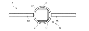
- FIG. 3 is a schematic partially enlarged plan view showing the vicinity of the frame of the biosensor according to the embodiment different from FIG.
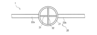
- FIG. 4 is a schematic partially enlarged plan view showing the vicinity of the frame of the biosensor of FIG. 1 when the measurement target does not move.
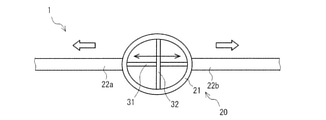
- FIG. 5 is a schematic partially enlarged plan view showing the vicinity of the frame of the biological sensor of FIG. 1 when the measurement target moves in the extension direction of the first strain sensor element.
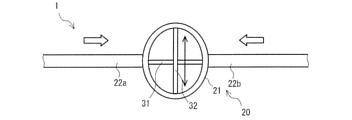
- FIG. 6 is a schematic partially enlarged plan view showing the vicinity of the frame of the biosensor of FIG. 1 when the measurement target moves in the contraction direction of the first strain sensor element.
- FIG. 7 is a schematic partially enlarged plan view showing the vicinity of the frame of the biosensor according to the embodiment different from FIGS. 1 and 3.
- the biological sensor includes a fixing member having an annular frame, a thread-shaped or band-shaped first strain sensor element and a second strain sensor element that expand and contract in the longitudinal direction, and the first strain sensor element. And the second strain sensor element is bridged over the frame so as to intersect, and the frame can be deformed at least in the longitudinal direction of the first strain sensor element and the longitudinal direction of the second strain sensor element. It is configured.
- the biosensor according to one aspect of the present invention can be used by being attached to the surface of a measurement target such as a human body, it is non-invasive and has an excellent wearing feeling. Further, when the measurement target moves in the extension direction of the first strain sensor element, the biosensor can detect the movement of the measurement target by the first strain sensor element. On the other hand, when the measurement target moves in the contraction direction of the first strain sensor element, the second strain sensor element that intersects with the first strain sensor element extends due to the deformation of the frame. The movement of the measurement target can be detected. That is, the biosensor can detect not only the movement of the measurement target in the extension direction of the first strain sensor element but also the movement in the contraction direction. Further, since it is not necessary to apply pretension to the biosensor at the time of mounting, the biosensor can be easily mounted.
- first strain sensor element and the second strain sensor element are orthogonal to each other.
- the intersecting position of the first strain sensor element and the second strain sensor element is the center position of the frame.
- the frame may be annular or polygonal annular.
- the fixing member has a rod-shaped or plate-shaped first reinforcing portion and a second reinforcing portion extending in opposite directions from the outer edge of the frame along the longitudinal direction of the first strain sensor element.
- the biological sensor 1 shown in FIGS. 1 and 2 includes a base material 10, a fixing member 20, a first strain sensor element 31, a second strain sensor element 32, and a holding portion 40. Since all of these components can be thin, the biosensor 1 can be thin as a whole.
- the fixing member 20 has an annular frame 21, and the first strain sensor element 31 and the second strain sensor element 32 are bridged over the frame 21 so as to intersect with each other. Further, the base material 10 fixes the fixing member 20.
- the biological sensor 1 is suitably used as a device for measuring human body behavior such as respiratory measurement.
- the base material 10 is strip-shaped and has flexibility.
- the base material 10 preferably has flexibility that does not hinder the expansion and contraction of the fixing member 20, and examples thereof include knits, woven fabrics, non-woven fabrics, rubbers, and leathers. Among them, highly elastic knits are particularly preferably used. Be done.
- FIG. 2 shows a configuration in which the fixing member 20 is fixed to the surface of one base material 10, but one base material 10 is further laminated on the surface side of the base material 10 and 2 It is preferable that the fixing member 20 is sandwiched and fixed by the sheet base material 10. By sandwiching the fixing member 20 between the two base materials 10 in this way, the wearing feeling can be improved.
- the base material 10 is hollowed out along the frame 21 of the fixing member 20 described later. That is, it is preferable that the base material 10 has a hole 11 that overlaps with the frame 21 of the fixing member 20 in a plan view.
- the size of the base material 10 is appropriately determined from the size of the fixing member 20 and the like, and can be, for example, 5 cm or more and 15 cm or less in the longitudinal direction and 2 cm or more and 5 cm or less in the width direction.
- the size of the biological sensor 1 in a plan view is determined by the size of the base material 10, and can be made relatively small in this way.
- An adhesive layer may be provided on the back surface of the base material 10 (the surface on which the fixing member 20 or the like is not arranged). By providing the adhesive layer on the back surface of the base material 10 in this way, it can be easily attached to or peeled off from the measurement target.
- the fixing member 20 has two rod-shaped or plate-shaped reinforcing portions extending in opposite directions from the outer edge of the frame 21 along the longitudinal direction of the first strain sensor element 31, as shown in FIG. It has 22 (first reinforcing portion 22a and second reinforcing portion 22b).
- the fixing member 20 is fixed to the base material 10 as described above.
- the method of fixing the fixing member 20 is not particularly limited, and examples thereof include a method of adhering the entire surface of the fixing member 20 in contact with the base material 10 to the base material 10.
- the frame 21 is configured to be deformable at least in the longitudinal direction of the first strain sensor element 31 and the longitudinal direction of the second strain sensor element 32.
- the frame 21 is an annular shape, and the frame 21 can be deformed in any direction. By making it deformable in any direction in this way, for example, even if the movement of the measurement target does not follow the longitudinal direction of the first strain sensor element 31 or the longitudinal direction of the second strain sensor element 32, the movement can be made. It can be easy to catch. However, it is not essential to deform in a direction other than the longitudinal direction of the first strain sensor element 31 and the longitudinal direction of the second strain sensor element 32.
- the material and ring thickness (width and diameter) of the frame 21 are determined so as to have an elastic force that can be deformed by the movement of the measurement target.
- urethane rubber having a width of 0.5 mm or more and 1 mm or less, ⁇ 0.1 mm or more 1
- a spring wire or the like of 0.0 mm or less.
- the spring wire include hard steel wire, piano wire, stainless steel wire, phosphor bronze for spring, and the like.
- the thickness of the ring of the frame 21 is uniform. By making the thickness of the ring of the frame 21 uniform, the first strain sensor element 31 and the second strain sensor element 32 can be extended in proportion to the movement of the measurement target, so that the measurement accuracy is improved.
- the size of the frame 21 (the outer diameter of the frame 21 in the biological sensor 1 of FIG. 1 because the frame 21 is annular) is determined by the sensitivity of the first strain sensor element 31 and the second strain sensor element 32 bridged to the frame 21. It is appropriately determined according to the above, but can be, for example, 1 cm or more and 3 cm or less.
- the reinforcing portion 22 is a member for accurately capturing the movement of the first strain sensor element 31 to be measured in the longitudinal direction and inducing the deformation of the frame 21. For example, when the measurement target is the human body and the movement is caused by respiration, the movement of the surface of the human body due to respiration is not uniform. By providing the reinforcing portion 22, if the movement of the surface of the human body can be captured at any portion where the reinforcing portion 22 is located, the movement can be transmitted to the frame 21.
- the first reinforcing portion 22a and the second reinforcing portion 22b which are the two reinforcing portions 22, are provided symmetrically with the frame 21 interposed therebetween.
- the first reinforcing portion 22a and the second reinforcing portion 22b may be arranged so as to be in line with the first strain sensor element 31.
- the same material as that of the frame 21 can be used.
- the width and length of the reinforcing portion 22 are appropriately optimized according to the measurement target. If the width or length of the reinforcing portion 22 is too short, the movement of the measurement target may not be accurately captured. On the contrary, if the width or length of the reinforcing portion 22 is too long, it becomes difficult to displace the reinforcing portion 22 due to the movement of the measurement target, and the amount of deformation of the frame 21 decreases, so that the measurement sensitivity may decrease.
- the reinforcing portion 22 is preferably arranged parallel to the longitudinal direction of the first strain sensor element 31 from the viewpoint of measurement sensitivity, but is arranged at an angle with the longitudinal direction of the first strain sensor element 31. Does not deny. Even if the first strain sensor element 31 is arranged at an angle with the longitudinal direction, the biosensor 1 has the same effect.
- the angle formed by the reinforcing portion 22 and the longitudinal direction of the first strain sensor element 31 is, for example, 30 degrees or less, and the smaller the angle, the more preferable.
- the first strain sensor element 31 and the second strain sensor element 32 are thread-shaped or band-shaped members that expand and contract in the longitudinal direction.
- the strain sensor element can directly grasp the movement of the measurement target. For example, in the case of measuring the respiration of the human body, since the change in the respiration state can be grasped in real time, it is possible to grasp some diseases based on respiration, for example, predictive data of respiratory failure without delay.
- the strain sensor element may be any as long as it has elasticity and its electrical characteristics change according to expansion and contraction, and a strain resistance element whose electrical resistance changes due to expansion and contraction is preferably used.
- a CNT strain sensor using carbon nanotubes hereinafter, also referred to as “CNT” is particularly preferably used.
- the strain sensor element can be configured to include a CNT bundle.
- This CNT bundle is a fiber bundle in which a plurality of CNTs (single fibers) are substantially oriented in the longitudinal direction of the CNT element, and is coated with a resin.
- the filamentous strain sensor element has a conductive portion made of a CNT bundle, a conductive layer in which CNT fibers and a resin are composited, and a resin coating film in this order from the center in the radial direction to the outside. Have. In the strain sensor element, the central CNT bundle is ruptured, and the interval between the ruptures is changed to cause a resistance change.
- the strain sensor element when the strain sensor element is strip-shaped, the strain sensor element can be composed of a resin composition containing a large number of CNT fibers.
- the band-shaped strain sensor element comprises a plurality of fiber bundle sheets in which a plurality of CNTs (single fibers) are substantially oriented in the longitudinal direction of the CNT element, and a resin covering the sheets of these fiber bundles.
- CNTs single fibers
- a resin covering the sheets of these fiber bundles Have.
- a single-walled nanotube (SWNT) or a multi-walled nanotube (MWNT) can be used.
- SWNT single-walled nanotube
- MWNT multi-walled nanotube
- MWNT is preferable from the viewpoint of conductivity and heat capacity, and MWNT having a diameter of 1.5 nm or more and 100 nm or less is more preferable.
- the CNT can be produced by a known method, for example, by a CVD method, an arc method, a laser ablation method, a DIPS method, a CoMoCAT method, or the like. Above all, it is preferable to produce CNTs (MWNTs) of a desired size by a CVD method using iron as a catalyst and ethylene gas from the viewpoint of being able to efficiently obtain CNTs (MWNTs). In this case, it is possible to obtain CNT crystals of a desired length grown in vertical orientation on a substrate such as a quartz glass substrate or a silicon substrate with an oxide film on which an iron or nickel thin film serving as a catalyst is formed. ..
- Both ends of the first strain sensor element 31 and the second strain sensor element 32 are connected to a measuring unit (not shown) for measuring resistance change via wiring 33.
- the wiring 33 is connected so that the resistance changes of the first strain sensor element 31 and the second strain sensor element 32 can be independently measured.
- the first strain sensor element 31 and the second strain sensor element 32 are orthogonal to each other, that is, the longitudinal direction of the first strain sensor element 31 and the longitudinal direction of the second strain sensor element 32 are orthogonal to each other. preferable.
- the biosensor 1 has the same effect even if the longitudinal direction of the first strain sensor element 31 and the longitudinal direction of the second strain sensor element 32 are not orthogonal to each other.
- the measurement sensitivity in the direction in which the sensor element 31 contracts can be increased.
- the biological sensor 2 shown in FIG. 3 shows a configuration in which the longitudinal direction of the first strain sensor element 31 and the longitudinal direction of the second strain sensor element 32 do not intersect.
- the extension line in the longitudinal direction of the first strain sensor element 31 and the extension line in the longitudinal direction of the second strain sensor element 32 are configured to intersect.
- the biosensor 2 in FIG. 3 includes two sets of the first strain sensor element 31 and the second strain sensor element 32. As described above, the biosensor 2 may be configured to include a plurality of sets of the first strain sensor element 31 and the second strain sensor element 32.
- the intersecting position of the first strain sensor element 31 and the second strain sensor element 32 can be set to an arbitrary position in the frame 21, but the center position of the frame 21 is preferable. That is, in the case of the frame 21 which is an annular shape, it is preferable that the intersection position of the first strain sensor element 31 and the second strain sensor element 32 is the center of the circle. By setting the intersection position as the center position of the frame 21 in this way, the measurement sensitivity can be improved.
- the first strain sensor element 31 and the second strain sensor element 32 are not connected at their crossing positions. That is, the first strain sensor element 31 and the second strain sensor element 32 are arranged so as to operate independently.
- the holding portion 40 is composed of two members, a first holding portion 40a and a second holding portion 40b.
- the two holding portions 40 (first holding portion 40a and second holding portion 40b) are rod-shaped or plate-shaped, and extend on the surface of the base material 10 along the longitudinal direction of the first strain sensor element 31.
- the two holding portions 40 are arranged on the outside of the frame 21 so as to face each other in the longitudinal direction of the second strain sensor element 32 with the frame 21 interposed therebetween.
- the holding portion 40 moves the base material 10 in the longitudinal direction of the first strain sensor element 31, for example, bends, and the movement of the measurement target is not sufficiently transmitted to the frame 21. Deter.
- the same material as that of the frame 21 can be used. Further, the width, length and distance from the frame 21 of the holding portion 40 are appropriately determined so that the movement of the measurement target is effectively transmitted to the frame 21.
- the biological sensor 1 can detect the movement of the measurement target with respect to the extension direction and the contraction direction of the first strain sensor element 31 without applying pretension to the first strain sensor element 31 and the second strain sensor element 32.
- the operating principle thereof will be described with reference to FIGS. 4 to 6.
- FIG. 4 is a diagram showing the vicinity of the frame 21 of the biosensor 1 when the measurement target does not move.
- the frame 21 is annular in order to maintain its original shape.
- FIG. 5 shows the case where the measurement target moves in the extension direction of the first strain sensor element 31.
- the frame 21 is deformed into an elliptical ring with the longitudinal direction of the first strain sensor element 31 as the long axis.
- the resistance of the first strain sensor element 31 changes.
- the second strain sensor element 32 is not pretensioned, the change in the frame 21 causes slack, and the resistance does not change. From the above, when the measurement target moves in the extension direction of the first strain sensor element 31, the movement can be detected from the resistance change of the first strain sensor element 31.
- FIG. 6 shows a case where the measurement target moves in the contraction direction of the first strain sensor element 31.
- the frame 21 is deformed into an elliptical ring with the longitudinal direction of the second strain sensor element 32 as the major axis.
- the change in the frame 21 causes slack, and the resistance does not change.
- the second strain sensor element 32 is stretched, the resistance of the second strain sensor element 32 changes. From the above, when the measurement target moves in the contraction direction of the first strain sensor element 31, the movement can be detected from the resistance change of the second strain sensor element 32.
- the resistance change of the first strain sensor element 31 or the resistance change of the second strain sensor element 32 regardless of whether the measurement target moves in the extension direction or the contraction direction of the first strain sensor element 31. Therefore, the movement can be detected.
- first strain sensor element 31 and the second strain sensor element 32 are not pretensioned, they function in the same manner even if the pretension is applied. Therefore, it does not deny that pretension is applied to the first strain sensor element 31 and the second strain sensor element 32. However, it is preferable that the pretension that deforms the frame 21 is not given.
- the biosensor 1 can be used by being attached to the surface of a measurement target such as a human body, it is non-invasive and has an excellent wearing feeling. Further, when the measurement target moves in the extension direction of the first strain sensor element 31, the biological sensor 1 can detect the movement of the measurement target by the first strain sensor element 31. On the other hand, when the measurement target moves in the contraction direction of the first strain sensor element 31, the second strain sensor element 32 that intersects with the first strain sensor element 31 extends due to the deformation of the frame 21, so that the second strain sensor element 32 causes the measurement target. The movement of the measurement target can be detected. That is, the biosensor 1 can detect not only the movement of the measurement target in the extension direction of the first strain sensor element 31 but also the movement in the contraction direction. Further, since it is not necessary to apply pretension to the biosensor 1 at the time of mounting, the biosensor 1 can be easily mounted.
- the fixing member has two reinforcing portions
- the number of reinforcing portions may be one or three or more.
- this reinforcement is not an essential component.
- the biosensor includes two holding portions, but the number of holding portions may be one or three or more. Further, this holding portion is not an essential component and may be omitted. In the case of a biosensor having no holding portion, it is possible to omit the base material.
- the biosensor of the present invention has the same effect even if it does not have a holding portion or a base material.
- the frame is annular
- other shapes are adopted as long as they are configured to be deformable at least in the longitudinal direction of the first strain sensor element and the longitudinal direction of the second strain sensor element. It is possible.
- Examples of such a frame shape include a polygonal annular shape.
- the frame 23 is a rhombic ring, which is one of the polygonal rings, is shown.
- the frame 23 it is preferable to configure the frame 23 so that the longitudinal direction of the first strain sensor element 31 and the longitudinal direction of the second strain sensor element 32 are part of the diagonal line of the frame 23.
- the longitudinal direction of the first strain sensor element 31 and the longitudinal direction of the second strain sensor element 32 form two diagonal lines having a diamond shape.
- the frame 23 has a diamond shape, the first strain sensor element 31 and the second strain sensor element 32 are orthogonal to each other, and the intersecting position thereof is the center position of the frame 23. With such a configuration, the measurement accuracy and measurement sensitivity of the biosensor 3 can be improved.
- the biosensor according to the present invention is non-invasive, has an excellent wearing feeling, can be easily worn, and can also detect movement in the contraction direction of the measurement target.
Landscapes
- Health & Medical Sciences (AREA)
- Physics & Mathematics (AREA)
- Life Sciences & Earth Sciences (AREA)
- General Physics & Mathematics (AREA)
- Molecular Biology (AREA)
- General Health & Medical Sciences (AREA)
- Engineering & Computer Science (AREA)
- Biomedical Technology (AREA)
- Heart & Thoracic Surgery (AREA)
- Medical Informatics (AREA)
- Biophysics (AREA)
- Surgery (AREA)
- Animal Behavior & Ethology (AREA)
- Pathology (AREA)
- Public Health (AREA)
- Veterinary Medicine (AREA)
- Physiology (AREA)
- Dentistry (AREA)
- Oral & Maxillofacial Surgery (AREA)
- Measurement Of The Respiration, Hearing Ability, Form, And Blood Characteristics Of Living Organisms (AREA)
- Measurement Of Length, Angles, Or The Like Using Electric Or Magnetic Means (AREA)
Abstract
本発明の一態様に係る生体センサ1は、環状のフレーム21を有する固定部材20と、長手方向に伸縮する糸状又は帯状の第1歪センサ素子31及び第2歪センサ素子32とを備え、第1歪センサ素子31及び第2歪センサ素子32が、交差するようにフレーム21に架け渡されており、フレーム21が、少なくとも第1歪センサ素子31の長手方向及び第2歪センサ素子32の長手方向に変形可能に構成されている。
Description
本発明は、生体センサに関する。
人や動物等の測定対象の動きをセンサによって検出して数値データ化する多様な試みがなされている。
これらの測定対象の動きを検出する装置として、伸縮に応じて抵抗値の変化する歪センサ素子を用いた歪センサが公知である(例えば国際公開第2019/031381号参照)。動きの検出に歪センサ素子を用いることで、非侵襲で装着感に優れるセンサを構成することができる。
歪センサ素子は、糸状あるいは帯状であり、その長手方向の伸縮による抵抗値の変化で測定対象の動きを検出することができる。この歪センサ素子を測定対象に対して自然長で装着した場合、前記歪センサ素子を伸ばす方向(以下、単に「伸び方向」ともいう)に測定対象が動くと、その伸びにより前記歪センサ素子が伸びて抵抗値が変化するので、測定対象の動きを検出することができる。これに対し、前記歪センサ素子を縮める方向(以下、単に「縮み方向」ともいう)に測定対象が動くと、前記歪センサ素子は自然長で装着されているため、前記歪センサは弛みを誘発するのみで、縮まない。つまり、前記歪センサに抵抗値の変化が生じないため、測定対象の動きを検出することができない。
縮み方向に測定対象が動いても測定対象の動きを検出できるようにするため、前記従来の歪センサは、前記歪センサ素子にあらかじめ張力(プリテンション)を与えて、つまり前記歪センサ素子を一定の長さに伸ばした状態で測定対象に装着される。この場合、縮み方向に測定対象が動いても、前記歪センサ素子が自然長へ戻る方向へ縮むため、前記歪センサ素子に抵抗値の変化が生じ、測定対象の動きを検出することができる。
このプリテンションは、不足すると前記歪センサ素子が弛むため縮み方向の動きの検出が不可能となる。一方、前記プリテンションが過剰となると、伸び方向に測定対象が動いた際に、計測回路側でレンジオーバーが生じて計測不可能となるといった不都合が生じ得る。このため前記プリテンションは適切に付与する必要があり、前記歪みセンサ素子の装着に手間がかかる。
本発明は、このような事情に基づいてなされたものであり、非侵襲で装着感に優れ、容易に装着可能であるとともに、測定対象の縮み方向の動きも検出することができる生体センサの提供を課題とする。
本発明の一態様に係る生体センサは、環状のフレームを有する固定部材と、長手方向に伸縮する糸状又は帯状の第1歪センサ素子及び第2歪センサ素子とを備え、前記第1歪センサ素子及び前記第2歪センサ素子が、交差するように前記フレームに架け渡されており、前記フレームが、少なくとも前記第1歪センサ素子の長手方向及び前記第2歪センサ素子の長手方向に変形可能に構成されている。
本発明の一態様に係る生体センサは、環状のフレームを有する固定部材と、長手方向に伸縮する糸状又は帯状の第1歪センサ素子及び第2歪センサ素子とを備え、前記第1歪センサ素子及び前記第2歪センサ素子が、交差するように前記フレームに架け渡されており、前記フレームが、少なくとも前記第1歪センサ素子の長手方向及び前記第2歪センサ素子の長手方向に変形可能に構成されている。
本発明の一態様に係る生体センサは、人体等の測定対象の表面に貼り付けて使用することができるので、非侵襲で装着感に優れる。また、当該生体センサは、前記第1歪センサ素子の伸び方向に前記測定対象が動く場合、前記第1歪センサ素子により前記測定対象の動きを検出できる。一方、前記第1歪センサ素子の縮み方向に前記測定対象が動く場合、前記フレームの変形により前記第1歪センサ素子と交差する前記第2歪センサ素子が伸びるので、前記第2歪センサ素子により前記測定対象の動きを検出できる。つまり、当該生体センサは、前記第1歪センサ素子の伸び方向への測定対象の動きに加え、縮み方向への動きも検出することができる。さらに、当該生体センサは、装着時にプリテンションを与えて装着する必要がないので、容易に装着可能である。
前記第1歪センサ素子と前記第2歪センサ素子とが、直交しているとよい。
前記第1歪センサ素子及び前記第2歪センサ素子の交差位置が、前記フレームの中心位置であるとよい。
前記フレームが、円環状又は多角環状であるとよい。
前記固定部材が、前記第1歪センサ素子の長手方向に沿って前記フレームの外縁から互いに逆方向に延出する棒状又は板状の第1補強部及び第2補強部を有するとよい。
可撓性を有し、前記固定部材を固定する帯状の基材と、前記基材の表面に前記第1歪センサ素子の長手方向に沿って延びる棒状又は板状の第1保持部及び第2保持部とを備え、前記第1保持部及び第2保持部が、前記フレームの外側に、前記フレームを挟んで前記第1歪センサ素子の長手方向に沿って配置されているとよい。
以下、適宜図面を参照しつつ、本発明の実施の形態を詳説する。
図1及び図2に示す生体センサ1は、基材10と、固定部材20と、第1歪センサ素子31及び第2歪センサ素子32と、保持部40とを備える。これらの構成要素はいずれも薄いものとすることができるので、当該生体センサ1は全体としても薄いものとすることができる。
固定部材20は、環状のフレーム21を有し、第1歪センサ素子31及び第2歪センサ素子32は、交差するようにフレーム21に架け渡されている。また、基材10は、固定部材20を固定する。当該生体センサ1は、呼吸計測等の人体挙動を測定するデバイスとして好適に用いられる。
<基材>
基材10は、帯状であり可撓性を有する。
基材10は、帯状であり可撓性を有する。
基材10としては、固定部材20の伸縮を妨げない可撓性を有するものが好ましく、例えばニット、織物、不織布、ゴム、皮革等が挙げられるが、中でも伸縮性の高いニットが特に好適に用いられる。
当該生体センサ1では、図2に示すように、1枚の基材10の表面に固定部材20と、保持部40及び後述する配線33が固定されている。なお、図2では、1枚の基材10の表面に固定部材20が固定されている構成を示しているが、この基材10の表面側にさらに1枚の基材10を積層し、2枚の基材10により固定部材20を挟んで固定する構成とすることが好ましい。このように2枚の基材10で固定部材20を挟むことで、装着感を向上できる。
基材10は、後述する固定部材20のフレーム21に沿ってくり抜かれていることが好ましい。つまり、基材10は、固定部材20のフレーム21と平面視で重なる孔11を有することが好ましい。このように基材10に孔11を設けることで、固定部材20の環の内側に固定部材20の動きを妨げるものがなくなるため、第1歪センサ素子31及び第2歪センサ素子32に測定対象の動きが集中し易くなり、当該生体センサ1の感度を高めることができる。
基材10の大きさは固定部材20等の大きさ等から適宜決定されるが、例えば長手方向が5cm以上15cm以下、幅方向が2cm以上5cm以下とできる。当該生体センサ1の平面視の大きさは、この基材10の大きさで決まるが、このように比較的小型のものとすることが可能である。
なお、基材10の裏面(固定部材20等が配設されていない面)に粘着層を設けてもよい。このように基材10の裏面に粘着層を設けることで、測定対象に容易に貼り付けたり、剥がしたりすることができる。
<固定部材>
固定部材20は、フレーム21に加え、図1に示すように、第1歪センサ素子31の長手方向に沿ってフレーム21の外縁から互いに逆方向に延出する棒状又は板状の2つの補強部22(第1補強部22a及び第2補強部22b)を有する。固定部材20は、上述のように基材10に固定されている。固定部材20の固定方法は、特に限定されないが、例えば固定部材20の基材10に接する全面を基材10に接着する方法を挙げることができる。
固定部材20は、フレーム21に加え、図1に示すように、第1歪センサ素子31の長手方向に沿ってフレーム21の外縁から互いに逆方向に延出する棒状又は板状の2つの補強部22(第1補強部22a及び第2補強部22b)を有する。固定部材20は、上述のように基材10に固定されている。固定部材20の固定方法は、特に限定されないが、例えば固定部材20の基材10に接する全面を基材10に接着する方法を挙げることができる。
(フレーム)
フレーム21は、少なくとも第1歪センサ素子31の長手方向及び第2歪センサ素子32の長手方向に変形可能に構成されている。図1の生体センサ1では、フレーム21は円環状であり、フレーム21は任意の方向に変形可能である。このように任意の方向に変形可能とすることで、例えば測定対象の動きが第1歪センサ素子31の長手方向や第2歪センサ素子32の長手方向に沿わないものであってもその動きを捉え易くすることができる。ただし、第1歪センサ素子31の長手方向及び第2歪センサ素子32の長手方向以外の方向に変形することは必須ではない。
フレーム21は、少なくとも第1歪センサ素子31の長手方向及び第2歪センサ素子32の長手方向に変形可能に構成されている。図1の生体センサ1では、フレーム21は円環状であり、フレーム21は任意の方向に変形可能である。このように任意の方向に変形可能とすることで、例えば測定対象の動きが第1歪センサ素子31の長手方向や第2歪センサ素子32の長手方向に沿わないものであってもその動きを捉え易くすることができる。ただし、第1歪センサ素子31の長手方向及び第2歪センサ素子32の長手方向以外の方向に変形することは必須ではない。
フレーム21は、測定対象の動きにより変形可能な弾性力を有するように材質及び環の太さ(幅や径)が決定され、例えば幅0.5mm以上1mm以下のウレタンラバー、φ0.1mm以上1.0mm以下のバネ線材等を採用可能である。前記バネ線材としては、硬鋼線、ピアノ線、ステンレス鋼線、バネ用リン青銅などを挙げることができる。なお、フレーム21の環の太さは一様であることが好ましい。フレーム21の環の太さを一様とすることで、測定対象の動きに比例して第1歪センサ素子31及び第2歪センサ素子32を伸ばすことができるので、測定精度が高められる。
フレーム21の大きさ(図1の生体センサ1ではフレーム21が円環状であるので、その外径)は、フレーム21に架け渡される第1歪センサ素子31及び第2歪センサ素子32の感度等に応じて適宜決定されるが、例えば1cm以上3cm以下とできる。
(補強部)
補強部22は、測定対象の第1歪センサ素子31の長手方向の動きを適確に捉え、フレーム21の変形を誘導するための部材である。例えば測定対象が人体であり、その動きが呼吸に起因する場合、呼吸による人体表面の動きは一様ではない。この補強部22を設けることで、補強部22が位置するいずれかの部位において人体表面の動きを捉えることができれば、その動きをフレーム21に伝えることができる。
補強部22は、測定対象の第1歪センサ素子31の長手方向の動きを適確に捉え、フレーム21の変形を誘導するための部材である。例えば測定対象が人体であり、その動きが呼吸に起因する場合、呼吸による人体表面の動きは一様ではない。この補強部22を設けることで、補強部22が位置するいずれかの部位において人体表面の動きを捉えることができれば、その動きをフレーム21に伝えることができる。
2つの補強部22である第1補強部22a及び第2補強部22bは、フレーム21を挟んで対称に設けられる。第1歪センサ素子31の長手方向の対称性を高めることで、測定対象の動きによるフレーム21の変形が不均一となることを抑止し、測定精度が高められる。また、測定精度の観点から、第1補強部22a及び第2補強部22bは、第1歪センサ素子31と一直線となるように配置されるとよい。
補強部22の材質としては、フレーム21と同じものを用いることができる。
補強部22の幅及び長さは、測定対象に応じて適宜最適化される。補強部22の幅や長さが短過ぎると、測定対象の動きを適確に捉えられないおそれがある。逆に、補強部22の幅や長さが長過ぎると、測定対象の動きにより補強部22を変位させ難くなり、フレーム21の変形量が低下するため、測定感度が低下するおそれがある。
なお、補強部22は、測定感度の観点から第1歪センサ素子31の長手方向と平行に配置されることが好ましいが、第1歪センサ素子31の長手方向と角度を持って配置されることを否定するものではない。第1歪センサ素子31の長手方向と角度を持って配置されても当該生体センサ1は同様の効果を奏する。なお、補強部22と第1歪センサ素子31の長手方向とのなす角度は、例えば30度以下とされ、小さいほど好ましい。
<歪センサ>
第1歪センサ素子31及び第2歪センサ素子32(以下、まとめて「歪センサ素子」ともいう)は、長手方向に伸縮する糸状又は帯状の部材である。歪センサ素子は、測定対象の動きを直接把握することができる。例えば人体の呼吸を測定する場合にあっては、呼吸の状態変化をリアルタイムに把握することができるので、呼吸に基づく何らかの諸疾患、例えば呼吸不全の予兆データを遅滞なく掌握できる。
第1歪センサ素子31及び第2歪センサ素子32(以下、まとめて「歪センサ素子」ともいう)は、長手方向に伸縮する糸状又は帯状の部材である。歪センサ素子は、測定対象の動きを直接把握することができる。例えば人体の呼吸を測定する場合にあっては、呼吸の状態変化をリアルタイムに把握することができるので、呼吸に基づく何らかの諸疾患、例えば呼吸不全の予兆データを遅滞なく掌握できる。
前記歪センサ素子は、伸縮性を有し、伸縮に応じて電気的特性が変化するものであればよく、伸縮により電気抵抗が変化する歪抵抗素子が好適に用いられる。中でも、前記歪センサ素子としては、カーボンナノチューブ(以下、「CNT」ともいう)を用いたCNT歪センサが特に好適に用いられる。
前記歪センサ素子が糸状である場合、この歪センサ素子は、CNT束を含んで構成することができる。このCNT束は、複数のCNT(単繊維)をCNT素子の長手方向に概略配向した繊維束であり、樹脂によって被覆される。糸状の前記歪センサ素子は、径方向の中心から外側に向けて、CNT束からなる導電部と、CNT繊維と樹脂とが複合された導電層と、樹脂製の被覆膜とをこの順で有する。前記歪センサ素子は、中心のCNT束が断裂し、その断裂した間隔が変化をすることで抵抗変化を生じさせることができる。
一方、前記歪センサ素子が帯状である場合、この歪センサ素子は多数のCNT繊維を含む樹脂組成物から構成することができる。具体的には、帯状の前記歪センサ素子は、複数のCNT(単繊維)をCNT素子の長手方向に概略配向した複数の繊維束のシートと、これらの繊維束のシートを被覆する樹脂とを有する。この歪センサ素子は、伸長歪が加えられた場合、内部のCNT繊維が切断してCNTの端部が離間したり、伸長歪みが緩和されて再接触したりして抵抗値に変化を生じる。
前記CNTとしては、単層のシングルウォールナノチューブ(SWNT)や、多層のマルチウォールナノチューブ(MWNT)のいずれも用いることができる。中でも、導電性及び熱容量等の点から、MWNTが好ましく、直径1.5nm以上100nm以下のMWNTがさらに好ましい。
前記CNTは、公知の方法で製造することができ、例えばCVD法、アーク法、レーザーアブレーション法、DIPS法、CoMoCAT法等により製造することができる。中でも、所望するサイズのCNT(MWNT)を効率的に得ることができる点から、鉄を触媒とし、エチレンガスを用いたCVD法により製造することが好ましい。この場合、石英ガラス基板や酸化膜付きシリコン基板等の基板に、触媒となる鉄又はニッケル薄膜を成膜した上に、垂直配向して成長した所望の長さのCNTの結晶を得ることができる。
第1歪センサ素子31及び第2歪センサ素子32の両端は、配線33を介して抵抗変化を測定する測定部(不図示)に接続される。なお、配線33は、第1歪センサ素子31及び第2歪センサ素子32の抵抗変化を独立して測定できるよう接続されている。
第1歪センサ素子31と第2歪センサ素子32とが直交していること、すなわち第1歪センサ素子31の長手方向と、第2歪センサ素子32の長手方向とは直交していることが好ましい。第1歪センサ素子31の長手方向と、第2歪センサ素子32の長手方向とは直交していなくとも当該生体センサ1は同様の効果を奏するが、これらを直交させることで、特に第1歪センサ素子31が縮む方向の測定感度を高められる。
一方、第1歪センサ素子31の長手方向と、第2歪センサ素子32の長手方向とは必ずしも交わらなくともよい。図3に示す生体センサ2は、第1歪センサ素子31の長手方向と、第2歪センサ素子32の長手方向とが交わらない場合の構成を示している。この場合、第1歪センサ素子31の長手方向の延長線と、第2歪センサ素子32の長手方向の延長線とが交わるように構成される。なお、図3の生体センサ2は、2組の第1歪センサ素子31及び第2歪センサ素子32を備えている。このように当該生体センサ2が、複数組の第1歪センサ素子31及び第2歪センサ素子32を備える構成とすることもできる。
第1歪センサ素子31及び第2歪センサ素子32の交差位置は、フレーム21内の任意の位置に取り得るが、中でもフレーム21の中心位置であることが好ましい。つまり、円環状であるフレーム21の場合、第1歪センサ素子31及び第2歪センサ素子32の交差位置を円の中心とすることが好ましい。このように前記交差位置をフレーム21の中心位置とすることで、測定感度を高められる。なお、第1歪センサ素子31及び第2歪センサ素子32は、その交差位置で連結されていない。つまり、第1歪センサ素子31及び第2歪センサ素子32は、独立して動作するように配設されている。
<保持部>
保持部40は、第1保持部40a及び第2保持部40bの2つの部材から構成されている。2つの保持部40(第1保持部40a及び第2保持部40b)は、棒状又は板状であり、基材10の表面に第1歪センサ素子31の長手方向に沿って延びている。この2つの保持部40は、フレーム21の外側に、フレーム21を挟んで第2歪センサ素子32の長手方向に対向するように配置されている。
保持部40は、第1保持部40a及び第2保持部40bの2つの部材から構成されている。2つの保持部40(第1保持部40a及び第2保持部40b)は、棒状又は板状であり、基材10の表面に第1歪センサ素子31の長手方向に沿って延びている。この2つの保持部40は、フレーム21の外側に、フレーム21を挟んで第2歪センサ素子32の長手方向に対向するように配置されている。
保持部40は、測定対象が動いた際に、第1歪センサ素子31の長手方向に基材10が動いて、例えば屈曲してしまい、測定対象の動きがフレーム21に十分に伝わらないことを抑止する。
保持部40の材質としては、フレーム21と同じものを用いることができる。また、保持部40の幅、長さ及びフレーム21からの離間距離は、測定対象の動きがフレーム21に効果的に伝達されるように適宜決定される。
<動作原理>
当該生体センサ1は、第1歪センサ素子31及び第2歪センサ素子32にプリテンションを付与することなく、第1歪センサ素子31の伸び方向及び縮み方向に対する測定対象の動きを検出できる。以下に、図4から図6を用いて、その動作原理を説明する。
当該生体センサ1は、第1歪センサ素子31及び第2歪センサ素子32にプリテンションを付与することなく、第1歪センサ素子31の伸び方向及び縮み方向に対する測定対象の動きを検出できる。以下に、図4から図6を用いて、その動作原理を説明する。
図4は、測定対象に動きがない場合の当該生体センサ1のフレーム21付近を示す図である。測定対象に動きがない場合、フレーム21は当初の形状を維持するため円環状である。
測定対象が第1歪センサ素子31の伸び方向に動いた場合を図5に示す。測定対象が第1歪センサ素子31の伸び方向に動くと、フレーム21は第1歪センサ素子31の長手方向を長軸とする楕円環状に変形する。この場合、第1歪センサ素子31が引き伸ばされるため、第1歪センサ素子31に抵抗変化が生じる。一方、第2歪センサ素子32は、プリテンションが与えられていないため、フレーム21の変化によって弛みが生じることとなり、抵抗変化は生じない。以上から、測定対象が第1歪センサ素子31の伸び方向に動いた場合は、第1歪センサ素子31の抵抗変化から、その動きを検出できる。
これに対し、測定対象が第1歪センサ素子31の縮み方向に動いた場合を図6に示す。測定対象が第1歪センサ素子31の縮み方向に動くと、フレーム21は第2歪センサ素子32の長手方向を長軸とする楕円環状に変形する。この場合、第1歪センサ素子31は、プリテンションが与えられていないため、フレーム21の変化によって弛みが生じることとなり、抵抗変化は生じない。逆に、第2歪センサ素子32が引き伸ばされるため、第2歪センサ素子32に抵抗変化が生じる。以上から、測定対象が第1歪センサ素子31の縮み方向に動いた場合は、第2歪センサ素子32の抵抗変化から、その動きを検出できる。
このように当該生体センサ1では、測定対象が第1歪センサ素子31の伸び方向及び縮み方向のいずれに動いても、第1歪センサ素子31の抵抗変化又は第2歪センサ素子32の抵抗変化により、その動きを検出することができる。
なお、上述の説明では第1歪センサ素子31及び第2歪センサ素子32にプリテンションが付与されていない場合を説明したが、プリテンションが与えられていても同様に機能する。従って、第1歪センサ素子31及び第2歪センサ素子32にプリテンションを付与することを否定するものではない。ただし、フレーム21が変形するようなプリテンションは与えられていないことが好ましい。
<利点>
当該生体センサ1は、人体等の測定対象の表面に貼り付けて使用することができるので、非侵襲で装着感に優れる。また、当該生体センサ1は、第1歪センサ素子31の伸び方向に前記測定対象が動く場合、第1歪センサ素子31により前記測定対象の動きを検出できる。一方、第1歪センサ素子31の縮み方向に前記測定対象が動く場合、フレーム21の変形により第1歪センサ素子31と交差する第2歪センサ素子32が伸びるので、第2歪センサ素子32により前記測定対象の動きを検出できる。つまり、当該生体センサ1は、第1歪センサ素子31の伸び方向への測定対象の動きに加え、縮み方向への動きも検出することができる。さらに、当該生体センサ1は、装着時にプリテンションを与えて装着する必要がないので、容易に装着可能である。
当該生体センサ1は、人体等の測定対象の表面に貼り付けて使用することができるので、非侵襲で装着感に優れる。また、当該生体センサ1は、第1歪センサ素子31の伸び方向に前記測定対象が動く場合、第1歪センサ素子31により前記測定対象の動きを検出できる。一方、第1歪センサ素子31の縮み方向に前記測定対象が動く場合、フレーム21の変形により第1歪センサ素子31と交差する第2歪センサ素子32が伸びるので、第2歪センサ素子32により前記測定対象の動きを検出できる。つまり、当該生体センサ1は、第1歪センサ素子31の伸び方向への測定対象の動きに加え、縮み方向への動きも検出することができる。さらに、当該生体センサ1は、装着時にプリテンションを与えて装着する必要がないので、容易に装着可能である。
[その他の実施形態]
前記実施形態は、本発明の構成を限定するものではない。従って、前記実施形態は、本明細書の記載及び技術常識に基づいて前記実施形態各部の構成要素の省略、置換又は追加が可能であり、それらは全て本発明の範囲に属するものと解釈されるべきである。
前記実施形態は、本発明の構成を限定するものではない。従って、前記実施形態は、本明細書の記載及び技術常識に基づいて前記実施形態各部の構成要素の省略、置換又は追加が可能であり、それらは全て本発明の範囲に属するものと解釈されるべきである。
前記実施形態では、固定部材が2つの補強部を有する場合を説明したが、補強部は1つまたは3つ以上であってもよい。ただし、この補強部は必須の構成要素ではない。フレームのみで測定対象の動きを捉えられる場合は、前記補強部は省略することができる。
前記実施形態では、当該生体センサが2つの保持部を備える場合を説明したが、保持部は1つまたは3つ以上であってもよい。また、この保持部は必須の構成要素ではなく、省略することもできる。保持部を有さない生体センサにあっては、基材を省略することも可能である。本発明の生体センサは、保持部や基材を有さない構成であっても、同様の効果を奏する。
前記実施形態では、フレームが円環状である場合を説明したが、少なくとも第1歪センサ素子の長手方向及び第2歪センサ素子の長手方向に変形可能に構成されていれば、他の形状を採用可能である。このようなフレームの形状としては、多角環状のものが挙げられる。図7に示す生体センサ3では、フレーム23が多角環状の1つである菱形環の場合を示している。
このような多角環状のフレーム23の場合には、第1歪センサ素子31の長手方向及び第2歪センサ素子32の長手方向がフレーム23の対角線の一部となるように構成することが好ましい。菱形のフレーム23の場合は、第1歪センサ素子31の長手方向及び第2歪センサ素子32の長手方向が菱形の2本の対角線を構成することとなる。このように構成すると、第1歪センサ素子31の長手方向の伸縮により、第2歪センサ素子32の長手方向にも変形が生じる。
さらに、フレーム23が菱形であることで、第1歪センサ素子31及び第2歪センサ素子32は直交し、かつその交差位置がフレーム23の中心位置となる。このような構成とすることで、当該生体センサ3の測定精度及び測定感度を高めることができる。
以上説明したように、本発明に係る生体センサは、非侵襲で装着感に優れ、容易に装着可能であるとともに、測定対象の縮み方向の動きも検出することができる。
1、2、3 生体センサ
10 基材
11 孔
20 固定部材
21、23 フレーム
22 補強部
22a 第1補強部
22b 第2補強部
31 第1歪センサ素子
32 第2歪センサ素子
33 配線
40 保持部
40a 第1保持部
40b 第2保持部
10 基材
11 孔
20 固定部材
21、23 フレーム
22 補強部
22a 第1補強部
22b 第2補強部
31 第1歪センサ素子
32 第2歪センサ素子
33 配線
40 保持部
40a 第1保持部
40b 第2保持部
Claims (6)
- 環状のフレームを有する固定部材と、
長手方向に伸縮する糸状又は帯状の第1歪センサ素子及び第2歪センサ素子と
を備え、
前記第1歪センサ素子及び前記第2歪センサ素子が、交差するように前記フレームに架け渡されており、
前記フレームが、少なくとも前記第1歪センサ素子の長手方向及び前記第2歪センサ素子の長手方向に変形可能に構成されている生体センサ。 - 前記第1歪センサ素子と前記第2歪センサ素子とが、直交している請求項1に記載の生体センサ。
- 前記第1歪センサ素子及び前記第2歪センサ素子の交差位置が、前記フレームの中心位置である請求項1又は請求項2に記載の生体センサ。
- 前記フレームが、円環状又は多角環状である請求項1、請求項2又は請求項3に記載の生体センサ。
- 前記固定部材が、前記第1歪センサ素子の長手方向に沿って前記フレームの外縁から互いに逆方向に延出する棒状又は板状の第1補強部及び第2補強部を有する請求項1から請求項4のいずれか1項に記載の生体センサ。
- 可撓性を有し、前記固定部材を固定する帯状の基材と、
前記基材の表面に前記第1歪センサ素子の長手方向に沿って延びる棒状又は板状の第1保持部及び第2保持部と
を備え、
前記第1保持部及び第2保持部が、前記フレームの外側に、前記フレームを挟んで前記第1歪センサ素子の長手方向に沿って配置されている請求項1から請求項5のいずれか1項に記載の生体センサ。
Priority Applications (2)
| Application Number | Priority Date | Filing Date | Title |
|---|---|---|---|
| CN202180059896.9A CN116134288B (zh) | 2020-07-21 | 2021-06-21 | 生物体传感器 |
| US18/156,589 US12578241B2 (en) | 2020-07-21 | 2023-01-19 | Strain sensor for detecting movement of measurement target |
Applications Claiming Priority (2)
| Application Number | Priority Date | Filing Date | Title |
|---|---|---|---|
| JP2020-124741 | 2020-07-21 | ||
| JP2020124741A JP7516947B2 (ja) | 2020-07-21 | 2020-07-21 | 生体センサ |
Related Child Applications (1)
| Application Number | Title | Priority Date | Filing Date |
|---|---|---|---|
| US18/156,589 Continuation US12578241B2 (en) | 2020-07-21 | 2023-01-19 | Strain sensor for detecting movement of measurement target |
Publications (1)
| Publication Number | Publication Date |
|---|---|
| WO2022019024A1 true WO2022019024A1 (ja) | 2022-01-27 |
Family
ID=79729454
Family Applications (1)
| Application Number | Title | Priority Date | Filing Date |
|---|---|---|---|
| PCT/JP2021/023375 Ceased WO2022019024A1 (ja) | 2020-07-21 | 2021-06-21 | 生体センサ |
Country Status (4)
| Country | Link |
|---|---|
| US (1) | US12578241B2 (ja) |
| JP (1) | JP7516947B2 (ja) |
| CN (1) | CN116134288B (ja) |
| WO (1) | WO2022019024A1 (ja) |
Families Citing this family (1)
| Publication number | Priority date | Publication date | Assignee | Title |
|---|---|---|---|---|
| WO2026004983A1 (ja) * | 2024-06-28 | 2026-01-02 | 学校法人順天堂 | 呼吸センサ |
Citations (7)
| Publication number | Priority date | Publication date | Assignee | Title |
|---|---|---|---|---|
| JPS63122210U (ja) * | 1987-02-03 | 1988-08-09 | ||
| JP2000304628A (ja) * | 1999-04-21 | 2000-11-02 | Yokogawa Koji Kk | 荷重測定方法および荷重センサ |
| JP2001074574A (ja) * | 1999-09-07 | 2001-03-23 | Fujikura Kasei Co Ltd | 接触検出装置 |
| JP2017203656A (ja) * | 2016-05-10 | 2017-11-16 | ヤマハ株式会社 | 歪みセンサユニット |
| JP2018096870A (ja) * | 2016-12-14 | 2018-06-21 | 国立大学法人神戸大学 | 動作計測装置、及び、動作計測用部材 |
| JP2019090722A (ja) * | 2017-11-15 | 2019-06-13 | ミネベアミツミ株式会社 | ひずみゲージ |
| WO2020013046A1 (ja) * | 2018-07-12 | 2020-01-16 | ミネベアミツミ株式会社 | ひずみゲージ、センサモジュール、軸受機構 |
Family Cites Families (14)
| Publication number | Priority date | Publication date | Assignee | Title |
|---|---|---|---|---|
| EP0003685A3 (en) * | 1978-02-13 | 1979-09-05 | Eitan Eilon | Load indicating device |
| DE10210332A1 (de) * | 2002-03-08 | 2003-10-02 | Festo Ag & Co | Kontraktionseinheit mit Positionssensoreinrichtung |
| EP2454566A1 (en) * | 2009-07-17 | 2012-05-23 | Skf Bv | Strain sensor |
| JP5636731B2 (ja) * | 2010-05-10 | 2014-12-10 | オリンパス株式会社 | 血圧センサシステム及びその血圧計測方法 |
| CN101832762A (zh) * | 2010-05-14 | 2010-09-15 | 北京品傲光电科技有限公司 | 光纤光栅应变传感器 |
| DE102012022447A1 (de) * | 2012-11-16 | 2014-05-22 | Storck Bicycle Gmbh | Kurbelarm, Kurbelgarnitur und Leistungsmesseinrichtung für ein zumindest teilweise muskelgetriebenes Fahrzeug oder Trainingsgerät mit Kurbelantrieb |
| CN103206912A (zh) * | 2013-04-24 | 2013-07-17 | 四川大学 | 一种磁致伸缩位移传感器测量装置 |
| CN103376172B (zh) * | 2013-07-10 | 2016-12-28 | 上海交通大学 | 用于微创外科手术机器人的六维力觉传感器 |
| EP3130287B1 (en) * | 2014-04-09 | 2022-05-11 | Bando Chemical Industries, Ltd. | Sensor device |
| JP6354948B2 (ja) * | 2014-09-16 | 2018-07-11 | ティアック株式会社 | ロードセル及びロードセルの製造方法 |
| CN107367239A (zh) * | 2016-05-12 | 2017-11-21 | 中国计量大学 | 一种环形结构高温管道外壁应变检测光纤光栅传感器件 |
| CN111343902A (zh) * | 2017-06-07 | 2020-06-26 | 得克萨斯大学体系董事会 | 无线、可穿戴且柔软的生物特征识别传感器 |
| JP6939885B2 (ja) | 2017-08-10 | 2021-09-22 | 株式会社村田製作所 | ひずみセンサとその製造方法 |
| CN110940365B (zh) * | 2019-12-10 | 2020-10-30 | 北京理工大学 | 一种增大干涉型光纤传感器灵敏度的机械放大结构 |
-
2020
- 2020-07-21 JP JP2020124741A patent/JP7516947B2/ja active Active
-
2021
- 2021-06-21 CN CN202180059896.9A patent/CN116134288B/zh active Active
- 2021-06-21 WO PCT/JP2021/023375 patent/WO2022019024A1/ja not_active Ceased
-
2023
- 2023-01-19 US US18/156,589 patent/US12578241B2/en active Active
Patent Citations (7)
| Publication number | Priority date | Publication date | Assignee | Title |
|---|---|---|---|---|
| JPS63122210U (ja) * | 1987-02-03 | 1988-08-09 | ||
| JP2000304628A (ja) * | 1999-04-21 | 2000-11-02 | Yokogawa Koji Kk | 荷重測定方法および荷重センサ |
| JP2001074574A (ja) * | 1999-09-07 | 2001-03-23 | Fujikura Kasei Co Ltd | 接触検出装置 |
| JP2017203656A (ja) * | 2016-05-10 | 2017-11-16 | ヤマハ株式会社 | 歪みセンサユニット |
| JP2018096870A (ja) * | 2016-12-14 | 2018-06-21 | 国立大学法人神戸大学 | 動作計測装置、及び、動作計測用部材 |
| JP2019090722A (ja) * | 2017-11-15 | 2019-06-13 | ミネベアミツミ株式会社 | ひずみゲージ |
| WO2020013046A1 (ja) * | 2018-07-12 | 2020-01-16 | ミネベアミツミ株式会社 | ひずみゲージ、センサモジュール、軸受機構 |
Also Published As
| Publication number | Publication date |
|---|---|
| CN116134288A (zh) | 2023-05-16 |
| CN116134288B (zh) | 2026-04-17 |
| US20230152169A1 (en) | 2023-05-18 |
| JP2022021252A (ja) | 2022-02-02 |
| US12578241B2 (en) | 2026-03-17 |
| JP7516947B2 (ja) | 2024-07-17 |
Similar Documents
| Publication | Publication Date | Title |
|---|---|---|
| ES3031739T3 (en) | A compliant tri-axial force sensor and method of fabricating the same | |
| Suzuki et al. | Rapid-response, widely stretchable sensor of aligned MWCNT/elastomer composites for human motion detection | |
| JP6701748B2 (ja) | 歪みセンサ素子 | |
| JP6488140B2 (ja) | 導電性伸縮基板および歪センサ | |
| JP2008170425A (ja) | 感圧シート | |
| WO2017195683A1 (ja) | 歪みセンサユニット | |
| US12086313B2 (en) | Motion detection system | |
| JP2017075847A (ja) | 動作検出デバイス | |
| CN112993144B (zh) | 压电器件、压电传感器和可穿戴装置 | |
| KR20200098513A (ko) | 파단-유도되는 기계-전기적 감도를 갖는 파이버-기반의 복합체 | |
| JP7516947B2 (ja) | 生体センサ | |
| EP4130937B1 (en) | Motion-detecting member | |
| JP2007315875A (ja) | 感圧センサ | |
| US12624938B2 (en) | Method for manufacturing strain sensor by control of thin-film crack using stress concentration structure and strain sensor manufactured using same | |
| WO2018131354A1 (ja) | 触覚センサー | |
| JP2018096870A (ja) | 動作計測装置、及び、動作計測用部材 | |
| JP7467828B2 (ja) | 歪センサユニット及び伸長量測定部材 | |
| JP7007802B2 (ja) | センサ及びセンサ装置 | |
| JP7380158B2 (ja) | 伸縮性回路基板および伸縮性デバイス | |
| KR102492375B1 (ko) | 압력 감지 의자 | |
| JP2020151294A (ja) | センサユニット及び検出装置 | |
| JP2006305658A (ja) | ロボットフィンガ | |
| KR20210091241A (ko) | 배선 기판 및 배선 기판의 제조 방법 | |
| Jamil et al. | Ultrastretchable Segmented Sensors for Functional Human–Machine Interfaces | |
| JP2024092712A (ja) | 歪センサ装置 |
Legal Events
| Date | Code | Title | Description |
|---|---|---|---|
| 121 | Ep: the epo has been informed by wipo that ep was designated in this application |
Ref document number: 21847246 Country of ref document: EP Kind code of ref document: A1 |
|
| NENP | Non-entry into the national phase |
Ref country code: DE |
|
| 122 | Ep: pct application non-entry in european phase |
Ref document number: 21847246 Country of ref document: EP Kind code of ref document: A1 |