WO2022018973A1 - 入力装置および情報処理装置 - Google Patents
入力装置および情報処理装置 Download PDFInfo
- Publication number
- WO2022018973A1 WO2022018973A1 PCT/JP2021/020744 JP2021020744W WO2022018973A1 WO 2022018973 A1 WO2022018973 A1 WO 2022018973A1 JP 2021020744 W JP2021020744 W JP 2021020744W WO 2022018973 A1 WO2022018973 A1 WO 2022018973A1
- Authority
- WO
- WIPO (PCT)
- Prior art keywords
- data
- input device
- control unit
- image
- detection mechanism
- Prior art date
- Legal status (The legal status is an assumption and is not a legal conclusion. Google has not performed a legal analysis and makes no representation as to the accuracy of the status listed.)
- Ceased
Links
Images


Classifications
-
- G—PHYSICS
- G02—OPTICS
- G02B—OPTICAL ELEMENTS, SYSTEMS OR APPARATUS
- G02B30/00—Optical systems or apparatus for producing three-dimensional [3D] effects, e.g. stereoscopic images
- G02B30/50—Optical systems or apparatus for producing three-dimensional [3D] effects, e.g. stereoscopic images the image being built up from image elements distributed over a 3D volume, e.g. voxels
- G02B30/56—Optical systems or apparatus for producing three-dimensional [3D] effects, e.g. stereoscopic images the image being built up from image elements distributed over a 3D volume, e.g. voxels by projecting aerial or floating images
-
- G—PHYSICS
- G06—COMPUTING OR CALCULATING; COUNTING
- G06F—ELECTRIC DIGITAL DATA PROCESSING
- G06F21/00—Security arrangements for protecting computers, components thereof, programs or data against unauthorised activity
- G06F21/60—Protecting data
- G06F21/602—Providing cryptographic facilities or services
-
- G—PHYSICS
- G06—COMPUTING OR CALCULATING; COUNTING
- G06F—ELECTRIC DIGITAL DATA PROCESSING
- G06F21/00—Security arrangements for protecting computers, components thereof, programs or data against unauthorised activity
- G06F21/60—Protecting data
- G06F21/62—Protecting access to data via a platform, e.g. using keys or access control rules
- G06F21/6218—Protecting access to data via a platform, e.g. using keys or access control rules to a system of files or objects, e.g. local or distributed file system or database
- G06F21/6245—Protecting personal data, e.g. for financial or medical purposes
-
- G—PHYSICS
- G06—COMPUTING OR CALCULATING; COUNTING
- G06F—ELECTRIC DIGITAL DATA PROCESSING
- G06F21/00—Security arrangements for protecting computers, components thereof, programs or data against unauthorised activity
- G06F21/70—Protecting specific internal or peripheral components, in which the protection of a component leads to protection of the entire computer
- G06F21/82—Protecting input, output or interconnection devices
- G06F21/83—Protecting input, output or interconnection devices input devices, e.g. keyboards, mice or controllers thereof
-
- G—PHYSICS
- G06—COMPUTING OR CALCULATING; COUNTING
- G06F—ELECTRIC DIGITAL DATA PROCESSING
- G06F3/00—Input arrangements for transferring data to be processed into a form capable of being handled by the computer; Output arrangements for transferring data from processing unit to output unit, e.g. interface arrangements
- G06F3/01—Input arrangements or combined input and output arrangements for interaction between user and computer
- G06F3/03—Arrangements for converting the position or the displacement of a member into a coded form
- G06F3/041—Digitisers, e.g. for touch screens or touch pads, characterised by the transducing means
- G06F3/0416—Control or interface arrangements specially adapted for digitisers
- G06F3/0418—Control or interface arrangements specially adapted for digitisers for error correction or compensation, e.g. based on parallax, calibration or alignment
-
- G—PHYSICS
- G06—COMPUTING OR CALCULATING; COUNTING
- G06F—ELECTRIC DIGITAL DATA PROCESSING
- G06F3/00—Input arrangements for transferring data to be processed into a form capable of being handled by the computer; Output arrangements for transferring data from processing unit to output unit, e.g. interface arrangements
- G06F3/01—Input arrangements or combined input and output arrangements for interaction between user and computer
- G06F3/03—Arrangements for converting the position or the displacement of a member into a coded form
- G06F3/041—Digitisers, e.g. for touch screens or touch pads, characterised by the transducing means
- G06F3/042—Digitisers, e.g. for touch screens or touch pads, characterised by the transducing means by opto-electronic means
-
- G—PHYSICS
- G06—COMPUTING OR CALCULATING; COUNTING
- G06F—ELECTRIC DIGITAL DATA PROCESSING
- G06F3/00—Input arrangements for transferring data to be processed into a form capable of being handled by the computer; Output arrangements for transferring data from processing unit to output unit, e.g. interface arrangements
- G06F3/01—Input arrangements or combined input and output arrangements for interaction between user and computer
- G06F3/048—Interaction techniques based on graphical user interfaces [GUI]
- G06F3/0487—Interaction techniques based on graphical user interfaces [GUI] using specific features provided by the input device, e.g. functions controlled by the rotation of a mouse with dual sensing arrangements, or of the nature of the input device, e.g. tap gestures based on pressure sensed by a digitiser
- G06F3/0488—Interaction techniques based on graphical user interfaces [GUI] using specific features provided by the input device, e.g. functions controlled by the rotation of a mouse with dual sensing arrangements, or of the nature of the input device, e.g. tap gestures based on pressure sensed by a digitiser using a touch-screen or digitiser, e.g. input of commands through traced gestures
- G06F3/04886—Interaction techniques based on graphical user interfaces [GUI] using specific features provided by the input device, e.g. functions controlled by the rotation of a mouse with dual sensing arrangements, or of the nature of the input device, e.g. tap gestures based on pressure sensed by a digitiser using a touch-screen or digitiser, e.g. input of commands through traced gestures by partitioning the display area of the touch-screen or the surface of the digitising tablet into independently controllable areas, e.g. virtual keyboards or menus
-
- G—PHYSICS
- G06—COMPUTING OR CALCULATING; COUNTING
- G06V—IMAGE OR VIDEO RECOGNITION OR UNDERSTANDING
- G06V40/00—Recognition of biometric, human-related or animal-related patterns in image or video data
- G06V40/10—Human or animal bodies, e.g. vehicle occupants or pedestrians; Body parts, e.g. hands
- G06V40/16—Human faces, e.g. facial parts, sketches or expressions
- G06V40/172—Classification, e.g. identification
-
- G—PHYSICS
- G06—COMPUTING OR CALCULATING; COUNTING
- G06F—ELECTRIC DIGITAL DATA PROCESSING
- G06F2203/00—Indexing scheme relating to G06F3/00 - G06F3/048
- G06F2203/048—Indexing scheme relating to G06F3/048
- G06F2203/04803—Split screen, i.e. subdividing the display area or the window area into separate subareas
-
- G—PHYSICS
- G06—COMPUTING OR CALCULATING; COUNTING
- G06F—ELECTRIC DIGITAL DATA PROCESSING
- G06F3/00—Input arrangements for transferring data to be processed into a form capable of being handled by the computer; Output arrangements for transferring data from processing unit to output unit, e.g. interface arrangements
- G06F3/01—Input arrangements or combined input and output arrangements for interaction between user and computer
- G06F3/03—Arrangements for converting the position or the displacement of a member into a coded form
- G06F3/041—Digitisers, e.g. for touch screens or touch pads, characterised by the transducing means
- G06F3/042—Digitisers, e.g. for touch screens or touch pads, characterised by the transducing means by opto-electronic means
- G06F3/0428—Digitisers, e.g. for touch screens or touch pads, characterised by the transducing means by opto-electronic means by sensing at the edges of the touch surface the interruption of optical paths, e.g. an illumination plane, parallel to the touch surface which may be virtual
Definitions
- the present invention relates to an input device for inputting information using the fingertips of a user.
- the present invention also relates to an information processing device including such an input device.
- the aerial image display device includes an aerial imaging mechanism and a display unit.
- the personal identification number display input unit includes a personal identification number display unit and a personal identification number input unit.
- a keypad for inputting a personal identification number is displayed on the display unit.
- the aerial imaging mechanism projects a keypad displayed on the display unit into space to form an image as an aerial image and displays it on the personal identification number display unit.
- the personal identification number input unit is provided with a detection mechanism for detecting an operation performed by a user on an aerial image of a keypad displayed on the personal identification number display unit.
- the detection mechanism is, for example, an infrared sensor, a camera, or the like, and detects the position of the user's fingertip on a plane including an aerial image of the keypad displayed on the personal identification number display unit.
- the user sequentially moves the fingertip to a predetermined position of the aerial image of the keypad displayed on the password display unit, and the password is input based on the detection result of the detection mechanism. Will be done.
- the inventor of the present application has developed an input device for a user to input information such as a personal identification number using an aerial image displayed in space, such as the automatic teller machine described in Patent Document 1.
- this input device it is preferable that high security is ensured so that information such as a password to be input is not illegally acquired by a third party.
- this input device has high security conforming to PCI PTS (Payment Card Industry Pin Transaction Security), which is a security standard for safely handling credit cards.
- PCI PTS Payment Card Industry Pin Transaction Security
- an object of the present invention is to provide an input device capable of ensuring high security in an input device for a user to input information such as a personal identification number using an aerial image displayed in an aerial image display area. To provide. Another object of the present invention is to provide an information processing device including such an input device.
- the input device of the present invention is an input device for inputting information using a user's fingertip, and is displayed on a display mechanism having a display surface for displaying an image and a display surface.
- An aerial imaging mechanism that forms an image as an aerial image by projecting the image into space, and a detection mechanism for detecting the position of the user's fingertip in the aerial image display area, which is the area where the aerial image is displayed, and input. It is equipped with a control board having a control unit for controlling the device and a fraud detection mechanism for detecting that fraudulent activity has been performed on the input device, and the aerial image display area is an input for inputting information.
- the control unit encrypts the image data, which is the data of the image displayed on the display surface, and sends it to the display mechanism, and the detection mechanism is the position data, which is the data of the position of the fingertip of the detected user. Is encrypted and transmitted to the control unit, and the fraud detection mechanism can at least detect fraudulent activity against the position data signal line that transmits position data from the detection mechanism to the control board and fraudulent activity against the control board. It is a feature.
- the control unit for controlling the input device encrypts the image data, which is the data of the image displayed on the display surface of the display mechanism, and transmits the image data to the display mechanism, and the user in the aerial image display area.
- the detection mechanism for detecting the position of the fingertip of the user encrypts the position data which is the data of the position of the fingertip of the detected user and transmits it to the control unit. Therefore, in the present invention, it is possible to prevent the image data transmitted from the control unit to the display mechanism and the position data transmitted from the detection mechanism to the control unit to be illegally acquired.
- the fraud detection mechanism for detecting that the fraudulent activity has been performed on the input device, at least the fraudulent activity on the position data signal line for transmitting the position data from the detection mechanism to the control board and the control board. Fraud can be detected. Therefore, in the present invention, when a fraudulent act is performed, it is possible to execute a predetermined process based on the detection result of the fraudulent act detection mechanism so that the position data or the like is not illegally acquired. Therefore, in the present invention, for example, it is possible to ensure high security of an input device compliant with PCI PTS.
- the fraud detection mechanism includes a destruction detection circuit for detecting at least one of a disconnection and a short circuit, and the destruction detection circuit covers at least a part of the position data signal line. It is preferable to have. With this configuration, if an attempt is made to illegally acquire position data from a position data signal line and a signal line for illegally acquiring position data is attached to the position data signal line, the failure detection circuit is disconnected or short-circuited. It is detected that fraudulent activity is being carried out. Therefore, when a fraudulent act is performed, it is possible to effectively prevent the position data from being illegally acquired by executing a predetermined process.
- the control unit when the control unit recognizes that the fraudulent activity has been performed based on the detection result of the fraudulent activity detection mechanism, the fraudulent activity occurs in the host control unit for controlling the host device on which the input device is mounted.
- the notification data for notifying the above it is preferable to make the control board unusable and at least one of erasing the data stored in the control unit.
- notification data notifying the occurrence of fraudulent activity is transmitted to the host control unit before the control board becomes unusable or the data stored in the control unit is erased.
- the upper control unit can recognize that a fraudulent act has been performed in the input device.
- the notification data includes data for identifying the location where fraudulent activity occurs.
- the host control unit can identify where in the input device the fraudulent activity was performed.
- the image displayed on the display surface is an image of a keypad including keys of a plurality of numbers
- the control unit changes the key arrangement of the keypad image displayed on the display surface each time.
- the input device of the present invention includes, for example, a card data reading mechanism for reading data recorded on a card, and the card data reading mechanism can be used for an information processing device electrically connected to a control unit. .. With this information processing device, it is possible to ensure high security of the input device. Further, in this information processing device, since the card data reading mechanism is electrically connected to the control unit of the input device, the control unit of the input device can manage the card data reading mechanism together.
- the information processing apparatus is, for example, as a card data reading mechanism, a magnetic head for reading magnetic data recorded on a card and a plurality of IC contacts in contact with external connection terminals of an IC chip formed on the card. It includes at least one of an IC contact block having a spring and a communication antenna for communicating information in a non-contact manner with the card.
- the information processing device includes, for example, a camera that acquires a face image for performing face recognition of a user, and the camera is electrically connected to a control unit.
- the control unit of the input device can manage the cameras together.
- the present invention it is possible to ensure high security of the input device in the input device for the user to input information such as a personal identification number by using the aerial image displayed in the aerial image display area. become.
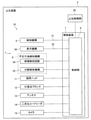
- FIG. 1 It is a schematic diagram for demonstrating the structure of the information processing apparatus which concerns on embodiment of this invention. It is a block diagram for demonstrating the structure of the information processing apparatus shown in FIG. It is a schematic diagram for demonstrating the configuration of the aerial image display apparatus used in the input apparatus shown in FIG. 1. It is a figure which shows an example of the aerial image displayed in the aerial image display area shown in FIG. It is a figure for demonstrating the display method of the aerial image which concerns on other embodiment of this invention. It is a figure for demonstrating the display method of the aerial image which concerns on other embodiment of this invention.
- FIG. 1 is a schematic diagram for explaining the configuration of the information processing apparatus 16 according to the embodiment of the present invention.
- FIG. 2 is a block diagram for explaining the configuration of the information processing apparatus 16 shown in FIG.
- FIG. 3 is a schematic diagram for explaining the configuration of the aerial image display device 3 used in the input device 1 shown in FIG.
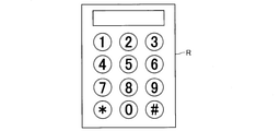
- FIG. 4 is a diagram showing an example of an aerial image displayed in the aerial image display area R shown in FIG.
- the input device 1 of the present embodiment is a device for inputting information using a user's fingertip, for example, an ATM, an authentication device at the time of payment of a credit card, an automatic ticket issuing machine, a vending machine, or an entry / exit. It is used by being mounted on a higher-level device 2 such as a management device. In the input device 1 of this embodiment, a personal identification number is input.
- the input device 1 includes an aerial image display device 3 that displays an aerial image in a three-dimensional space, and a detection mechanism 4 for detecting the position of a user's fingertip in the aerial image display area R, which is an area where the aerial image is displayed. It includes an aerial image display device 3 and a housing 5 in which the detection mechanism 4 is housed.
- the input device 1 includes a control board (control board) 7 having a control unit 6 for controlling the input device 1 and a fraud detection mechanism 8 for detecting that a fraudulent act has been performed on the input device 1.
- the housing 5 includes a magnetic head 11 for reading magnetic data recorded on the card, an IC contact block 12 having a plurality of IC contact springs that come into contact with external connection terminals of the IC chip formed on the card, and a card. And an antenna 13 for communication for communicating information in a non-contact manner are housed.
- the magnetic head 11, the IC contact block 12, and the antenna 13 of the present embodiment are card data reading mechanisms for reading the data recorded on the card.
- the housing 5 houses a two-dimensional code reader 14 for reading a two-dimensional code such as a QR code (registered trademark) and a camera 15 for acquiring a face image for performing face recognition of a user.
- the information processing device 16 is composed of an input device 1, a magnetic head 11, an IC contact block 12, an antenna 13, a two-dimensional code reader 14, a camera 15, and the like.
- the information processing device 16 is mounted on the host device 2.
- the aerial image display device 3 includes a display mechanism 20 having a display surface 20a for displaying an image, and an aerial imaging mechanism 21 for forming an image as an aerial image by projecting an image displayed on the display surface 20a into space. ing.
- the aerial imaging mechanism 21 includes a beam splitter 22 and a retroreflective material 23.
- the Y direction in FIG. 3 which is orthogonal to the vertical direction (vertical direction), is the left-right direction
- the direction orthogonal to the up-down direction and the left-right direction is the front-back direction.
- the X1 direction side of FIG. 3, which is one side in the front-rear direction is referred to as the "front" side
- the X2 direction side of FIG. 3, which is the opposite side is referred to as the "rear" side.
- a user standing on the front side of the input device 1 performs a predetermined operation on the front side of the input device 1.
- the display mechanism 20 is, for example, a liquid crystal display or an organic EL display, and the display surface 20a is a screen of the display.
- the display surface 20a faces diagonally forward and downward.
- the beam splitter 22 is formed in a flat plate shape.
- the beam splitter 22 is arranged on the front side of the display mechanism 20.
- the beam splitter 22 reflects a part of the light emitted from the display surface 20a. That is, one surface of the beam splitter 22 is a reflecting surface 22a that reflects a part of the light emitted from the display surface 20a.
- the reflective surface 22a faces diagonally backward and downward.
- the retroreflective material 23 is formed in a flat plate shape.
- the retroreflective material 23 is arranged below the display mechanism 20 and behind the beam splitter 22.
- the light reflected by the beam splitter 22 is incident on the retroreflective material 23.
- the retroreflective material 23 reflects the incident light toward the beam splitter 22 in the same direction as the incident direction. That is, one surface of the retroreflective material 23 is a retroreflective surface 23a on which the light reflected by the beam splitter 22 is incident and the incident light is reflected toward the beam splitter 22 in the same direction as the incident direction. ..
- a 1/4 wave plate is attached to the retroreflective surface 23a.
- the retroreflective surface 23a faces diagonally forward and upward.
- a part of the light emitted from the display surface 20a of the display mechanism 20 is reflected by the reflection surface 22a of the beam splitter 22 and is incident on the retroreflective surface 23a of the retroreflective material 23.
- the light reflected by the reflecting surface 22a heads diagonally backward and downward.
- the light incident on the retroreflective surface 23a is reflected in the same direction as the light incident on the retroreflective surface 23a.
- the light reflected by the retroreflective surface 23a goes diagonally forward and upward and passes through the beam splitter 22.
- the optical axis L1 of the light emitted from the display surface 20a and the optical axis L2 of the light reflected by the beam splitter 22 are orthogonal to each other. Further, the optical axis of the light reflected by the retroreflective material 23 coincides with the optical axis L2.
- An aerial image is formed in the aerial image display area R by the light transmitted through the beam splitter 22.
- the aerial image display area R is arranged on the diagonally front upper side of the beam splitter 22.
- the aerial image formed in the aerial image display area R is recognized by the user standing on the front side of the input device 1 as an image tilted toward the lower side toward the front side.
- the housing 5 is formed in the shape of a rectangular parallelepiped box, for example.
- the housing 5 is formed with a slit groove (not shown) through which the card is passed when the magnetic data of the card is read.
- the user manually moves the card along the slit groove.
- the housing 5 is formed with a card insertion hole (not shown) into which a card is inserted when the IC contact spring of the IC contact block 12 is brought into contact with the external connection terminal of the card to communicate data. There is.
- the IC contact spring of the IC contact block 12 is brought into contact with the external connection terminal of the card to communicate data, the user manually inserts the card into the card insertion hole.
- the housing 5 includes a frame body 24 that surrounds the aerial image display area R.
- the frame body 24 is formed in a rectangular or square frame shape and also in a flat plate shape.
- the frame body 24 constitutes the front upper surface of the housing 5.
- the frame body 24 formed in a flat plate shape is inclined toward the lower side toward the front side.
- the inner peripheral side of the frame body 24 is an opening 24a leading to the inside of the housing 5.
- the opening 24a is formed in a rectangular shape or a square shape.
- the aerial image display area R is formed in the opening 24a.
- the aerial image display area R is an input unit 25 for the user to input information using a fingertip.
- the detection mechanism 4 detects the position of the user's fingertip in the aerial image display area R. That is, the input unit 25 is included in the detection range of the detection mechanism 4.
- the detection mechanism 4 is an optical sensor. Specifically, the detection mechanism 4 is an infrared sensor. Further, the detection mechanism 4 is a line sensor.
- the detection mechanism 4 is equipped with a plurality of light emitting units that emit infrared light, a plurality of light receiving units that emit infrared light emitted from the light emitting unit and reflected by the user's fingertip, and a plurality of light emitting units and light receiving units. It is equipped with a substrate to be used. That is, the detection mechanism 4 is a reflection type optical sensor.
- the detection mechanism 4 is attached to the housing 5. Further, the detection mechanism 4 is arranged on the side of the opening 24a. The detection mechanism 4 detects the position of the user's fingertip in the plane including the aerial image display area R (that is, in the plane including the input unit 25).
- a CPU Central Processing Unit
- This CPU encrypts the position data which is the data of the position of the user's fingertip detected by the detection mechanism 4.
- the magnetic head 11 is arranged so as to face the slit groove from one side surface of the slit groove formed in the housing 5.
- the magnetic head 11 includes a core, a coil wound around the core, a circuit board to which the coil is electrically connected, and the like.
- a CPU is mounted on the circuit board. This CPU encrypts the magnetic data read from the card.
- the IC contact block 12 is arranged so as to face the card insertion hole from one side surface of the card insertion hole formed in the housing 5.
- the IC contact block 12 includes a spring holding member that holds a plurality of IC contact springs, a circuit board to which a plurality of IC contact springs are electrically connected, and the like.
- a CPU is mounted on the circuit board. This CPU encrypts the data read from the card using the IC contact spring.
- the antenna 13 is an antenna coil (loop antenna) formed by winding the coil in an annular shape.
- the antenna 13 is mounted on a substrate formed in a rectangular or square frame shape. This substrate is fixed to the rear lower surface of the frame body 24. Further, this substrate is arranged on the outer peripheral side of the opening 24a, and the antenna 13 is arranged on the outer peripheral side of the aerial image display area R so as to surround the aerial image display area R.
- the two-dimensional code reader 14 includes a two-dimensional code reading unit.
- the two-dimensional code reader 14 is housed in the housing 5 so that the reading unit of the two-dimensional code faces the front side, for example.
- the camera 15 is arranged, for example, below the opening 24a.
- the control board 7 is a rigid board such as a glass epoxy board or a flexible printed circuit board.
- the control board 7 is attached to the housing 5.
- the control unit 6 is mounted on the control board 7.
- a detection mechanism 4, a display mechanism 20, a magnetic head 11, an IC contact block 12, an antenna 13, a two-dimensional code reader 14, and a camera 15 are electrically connected to the control unit 6. In this embodiment, these configurations are wiredly connected to the control unit 6.
- the control unit 6 is electrically connected to the upper control unit 28 for controlling the upper device 2.
- the control unit 6 is connected to the upper control unit 28 by wire and wirelessly.
- the control unit 6 encrypts the image data, which is the image data displayed on the display surface 20a, and transmits the image data to the display mechanism 20.
- the detection mechanism 4 includes a CPU that encrypts the position data which is the data of the position of the fingertip of the detected user.
- the detection mechanism 4 encrypts the position data and transmits it to the control unit 6.
- the magnetic head 11 includes a CPU that encrypts magnetic data
- the IC contact block 12 includes a CPU that encrypts data read from a card using an IC contact spring.
- the magnetic head 11 and the IC contact block 12 encrypt the data read from the card and transmit it to the control unit 6.
- the two-dimensional code reader 14 and the camera 15 also transmit the encrypted data to the control unit 6.
- the data recorded on the card is read by the magnetic head 11, the IC contact block 12, or the antenna 13.
- the read data is transmitted to the control unit 6.
- a personal identification number is input in the input unit 25.
- the display mechanism 20 displays a keypad for inputting the personal identification number on the display surface 20a
- the aerial imaging mechanism 21 displays the keypad displayed on the display surface 20a. Is displayed in the aerial image display area R as an aerial image (see FIG. 4).
- the user inputs the password using the keypad displayed in the aerial image display area R. Specifically, the user inputs the password by sequentially moving the fingertip to the position of the key of a predetermined number in the keypad displayed in the aerial image display area R. That is, the user inputs a personal identification number by sequentially performing an operation (pointing operation) in which the user points a predetermined key in the keypad displayed in the aerial image display area R with a fingertip.
- pointing operation pointing operation
- the control unit 6 recognizes the key (number) inserted by the pointing operation based on the detection result of the detection mechanism 4 (that is, the detection result of the position of the fingertip of the user). That is, the control unit 6 recognizes the password input by the input unit 25 based on the detection result of the detection mechanism 4.
- the control unit 6 collates the password data recognized based on the detection result of the detection mechanism 4 with the data read from the card, and transmits the collation result data to the upper control unit 28.
- the fraud detection mechanism 8 includes a destruction detection circuit 30 for detecting at least one of a disconnection and a short circuit.
- the fraud detection mechanism 8 of this embodiment has a destruction detection circuit 30 that covers a part or the whole of a position data signal line 31 that transmits encrypted position data from the detection mechanism 4 to the control unit 6, and a display mechanism 20 from the control unit 6.
- a destruction detection circuit 30 that covers a part or the whole of an image data signal line 32 that transmits encrypted image data, and a destruction detection circuit 30 that covers a part or the whole of the control board 7 are provided.
- the destruction detection circuit 30 is composed of, for example, one conductor pattern.
- the destruction detection circuit 30 is electrically connected to the control unit 6.
- the destruction detection circuit 30 is formed on, for example, a flexible printed circuit board (FPC).
- FPC flexible printed circuit board
- the destruction detection circuit 30 covering the position data signal line 31 is formed in the FPC, for example, in this FPC, the data signal layer in which the data signal circuit to be the position data signal line 31 is formed and the destruction detection circuit 30 are formed.
- the fracture detection circuit layer to be formed is laminated via an insulating layer.
- the destruction detection circuit 30 covering the image data signal line 32 is formed in the FPC, for example, in this FPC, the data signal layer in which the data signal circuit to be the image data signal line 32 is formed and the destruction detection The destruction detection circuit layer on which the circuit 30 is formed is laminated via an insulating layer.
- the fraud detection mechanism 8 includes a disassembly detection mechanism 35 for detecting that the input device 1 has been disassembled.
- the fraud detection mechanism 8 includes, for example, a disassembly detection mechanism 35 for detecting that the housing 5 has been disassembled (for example, the frame body 24 has been removed).
- the fraud detection mechanism 8 includes, for example, a disassembly detection mechanism 35 for detecting that the control board 7 has been removed from the housing 5.
- the fraud detection mechanism 8 is, for example, a disassembly detection mechanism 35 for detecting that the control board 7 has been removed from the housing 5, and a detection mechanism 4 for detecting that the detection mechanism 4 has been removed from the housing 5.
- the decomposition detection mechanism 35 of the above is provided.
- the disassembly detection mechanism 35 is electrically connected to the control unit 6.
- the disassembly detection mechanism 35 includes, for example, a contact-type detection switch having a contact electrode or the like.
- a contact-type detection switch having a contact electrode or the like.
- the contact electrode of the detection switch is pushed by the convex portion formed on the housing 5.
- the detection switch is in a conductive state.
- the control board 7 and the detection mechanism 4 are removed from the housing 5, the contact electrode of the detection switch is not pushed by the convex portion and becomes a non-conducting state. Therefore, the control board 7 and the detection mechanism 4 are removed from the housing 5. Is detected to have been removed.
- the position data signal line 31, the image such as attaching a data acquisition signal line to the position data signal line 31, the image data signal line 32, or the control board 7 in order to illegally acquire data from the input device 1. If an illegal act is performed on the data signal line 32 or the control board 7, the destruction detection circuit 30 is disconnected or short-circuited. Therefore, the destruction detection circuit 30 causes the position data signal line 31, the image data signal line 32, and the control board 7 to be connected. It is possible to detect fraudulent activity against each.
- the fraud detection mechanism 8 is provided with the disassembly detection mechanism 35 for detecting that the housing 5 has been disassembled
- the housing 5 is disassembled. Since the decomposition detection mechanism 35 detects that the housing 5 has been disassembled, the decomposition detection mechanism 35 detects the detection mechanism 4, the control board 7, the display mechanism 20, the position data signal line 31, and the image data signal line 32, respectively. It is possible to detect fraudulent acts against. Further, in this case, the decomposition detection mechanism 35 makes it possible to detect fraudulent acts against each of the magnetic head 11 and the IC contact block 12 housed in the housing 5.
- the disassembly detection mechanism 35 for detecting that the control board 7 has been removed from the housing 5 and the disassembly detection mechanism 35 for detecting that the detection mechanism 4 has been removed from the housing 5 are illegally acted.
- the detection mechanism 8 is provided, the disassembly detection mechanism 35 makes it possible to detect fraudulent acts against each of the detection mechanism 4 and the control board 7.
- the fraud detection mechanism 8 is provided with a disassembly detection mechanism 35 for detecting that the control board 7 has been removed from the housing 5, the disassembly detection mechanism 35 detects fraudulent activity against the control board 7. It is possible to detect it.
- the fraud detection mechanism 8 can at least detect fraudulent activity against the control board 7, fraudulent activity against the position data signal line 31, and fraudulent activity against the image data signal line 32, and at least control. It is possible to physically protect the substrate 7, the position data signal line 31, and the image data signal line 32. If the fraud detection mechanism 8 includes a disassembly detection mechanism 35 for detecting that the housing 5 has been disassembled, the detection mechanism 4, the control board 7, the magnetic head 11, the IC contact block 12, and the display mechanism. 20, the position data signal line 31 and the image data signal line 32 can be physically protected.
- control unit 6 When the control unit 6 recognizes that the fraudulent activity has been performed based on the detection result of the fraudulent activity detection mechanism 8, it executes a predetermined process. Specifically, when the control unit 6 recognizes that the fraudulent activity has been performed based on the detection result of the fraudulent activity detection mechanism 8, the control unit 6 transmits notification data notifying the occurrence of the fraudulent activity to the upper control unit 28. Further, the control unit 6 either disables the control board 7 after transmitting the notification data to the upper control unit 28, or erases the data stored in the control unit 6. Perform one of the processes.
- the notification data notified to the upper control unit 28 includes data for identifying the location where fraudulent activity has occurred. For example, when the failure detection circuit 30 is disconnected or short-circuited, the notification data includes data for identifying the failure detection circuit 30 where the disconnection or short circuit has occurred.
- the notification data includes data for identifying the disassembly detection mechanism 35 that has detected that the input device 1 has been disassembled (that is,). , Data for identifying which part of the input device 1 has been removed) is included.
- the control unit 6 encrypts the image data, which is the image data displayed on the display surface 20a of the display mechanism 20, and transmits the image data to the display mechanism 20, and the detection mechanism 4 detects.
- the position data which is the data of the position of the fingertip of the user, is encrypted and transmitted to the control unit 6. Therefore, in the present embodiment, it is possible to prevent unauthorized acquisition of the image data transmitted from the control unit 6 to the display mechanism 20 and the position data transmitted from the detection mechanism 4 to the control unit 6.
- the control unit 6 performs at least one of the process of disabling the control board 7 and the process of erasing the data stored in the control unit 6. Therefore, in this embodiment, for example, it is possible to ensure high security of the input device 1 compliant with PCI PTS.
- the control unit 6 when the control unit 6 recognizes that the fraudulent activity has been performed based on the detection result of the fraudulent activity detection mechanism 8, the control board 7 becomes unusable or is stored in the control unit 6. Before the data is erased, the notification data notifying the occurrence of fraudulent activity is transmitted to the upper control unit 28. Therefore, in the present embodiment, the upper control unit 28 can recognize that the input device 1 has performed an illegal act. Further, in the present embodiment, since the notification data includes data for identifying the location where the fraudulent activity has occurred, the host control unit 28 identifies the location of the input device 1 where the fraudulent activity was performed. It will be possible to do.
- the magnetic head 11, the IC contact block 12, the antenna 13, the two-dimensional code reader 14, and the camera 15 are electrically connected to the control unit 6 of the input device 1. Therefore, in the present embodiment, the control unit 6 of the input device 1 can manage the magnetic head 11, the IC contact block 12, the antenna 13, the two-dimensional code reader 14, and the camera 15 together. Therefore, in this embodiment, it is possible to simplify the processing in the upper control unit 28.
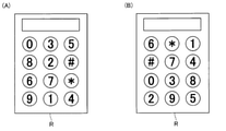
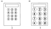
- Example of changing the display method of the aerial image 5 and 6 are diagrams for explaining a method of displaying an aerial image according to another embodiment of the present invention.
- control unit 6 may change the arrangement of the keys of the image of the keypad displayed on the display surface 20a of the display mechanism 20 each time. That is, the arrangement of the keys of the keypad displayed as an aerial image in the aerial image display area R may be changed each time.
- the keypad key arrangement shown in FIG. 4 is changed to the arrangement shown in FIG. 5A or the arrangement shown in FIG. 5B.
- the control unit 6 may change the size of the key of the image of the keypad displayed on the display surface 20a each time. That is, the size of the key on the keypad displayed as an aerial image in the aerial image display area R may be changed each time. In this case, for example, the size of the key of the keypad shown in FIG. 4 is changed to the size shown in FIG. 6A or the size shown in FIG. 6B.
- the fraud detection mechanism 8 does not have to include the decomposition detection mechanism 35. In this case, the fraud detection mechanism 8 does not have to include the destruction detection circuit 30 that covers the image data signal line 32.
- the fraud detection mechanism 8 does not include the destruction detection circuit 30 and the disassembly detection mechanism 35 that cover the image data signal line 32, the fraud detection mechanism 8 is used to counter the fraudulent activity against the control board 7 and the position data signal line 31. Fraud can be detected.
- the fraud detection mechanism 8 when the fraud detection mechanism 8 includes a disassembly detection mechanism 35 for detecting that the housing 5 has been disassembled, the fraud detection mechanism 8 includes a destruction detection circuit 30. It doesn't have to be. Further, in the above-described form, the notification data transmitted to the upper control unit 28 may not include data for identifying the location where fraudulent activity occurs. Further, in the above-described embodiment, the control unit 6 does not have to transmit the notification data to the upper control unit 28.
- the fraud detection mechanism 8 includes a destruction detection circuit 30 that covers a part or the whole of the magnetic head 11, a destruction detection circuit 30 that covers a part or the whole of the IC contact block 12, and a control unit 6 from the magnetic head 11.
- Destruction detection circuit 30 that covers a part or the whole of the data signal line that transmits the encrypted magnetic data, and destruction that covers a part or the whole of the data signal line that transmits the encrypted data from the IC contact block 12 to the control unit 6. It may be provided with the detection circuit 30.
- the user may input information other than the personal identification number using the image of the keypad displayed in the aerial image display area R. Further, in the above-described embodiment, the user may input the personal identification number by performing an operation of tracing a predetermined position in the frame displayed in the aerial image display area R with a fingertip. In this case, the image of the keypad is not displayed in the aerial image display area R. Even in this case, the control unit 6 recognizes the password input by the input unit 25 based on the detection result of the detection mechanism 4. Further, in the above-described form, the user's signature may be input by the input unit 25 in addition to or instead of the personal identification number. In this case, the user, for example, moves his / her fingertip in the frame displayed in the aerial image display area R to input the signature.
- the detection mechanism 4 is a transmissive optical sensor having a plurality of light emitting units that emit infrared light and a plurality of light receiving units that are incident with infrared light emitted from the light emitting unit. Is also good.
- the detection mechanism 4 has a first detection mechanism having a light emitting unit and a light receiving unit arranged so as to sandwich the aerial image display region R in the left-right direction, and is orthogonal to the optical axis L2 and orthogonal to the left-right direction. It is composed of a second detection mechanism having a light emitting unit and a light receiving unit arranged so as to sandwich the aerial image display region R in the direction in which the image is displayed.
- the detection mechanism 4 may be a capacitance sensor or a motion sensor. Further, the detection mechanism 4 may be composed of two cameras.
- information communication with the information processing device 16 using the antenna 13 may be performed by an information recording medium other than a card, or an electronic device such as a smartphone. May be.
- the information processing apparatus 16 does not have to include the two-dimensional code reader 14. In this case, the two-dimensional code may be read by the camera 15. Further, in the above-described embodiment, the information processing apparatus 16 does not have to include the camera 15. Further, the information processing apparatus 16 does not have to include at least one of the magnetic head 11, the IC contact block 12, and the antenna 13.
Landscapes
- Engineering & Computer Science (AREA)
- Theoretical Computer Science (AREA)
- Physics & Mathematics (AREA)
- General Engineering & Computer Science (AREA)
- General Physics & Mathematics (AREA)
- Computer Hardware Design (AREA)
- Health & Medical Sciences (AREA)
- General Health & Medical Sciences (AREA)
- Human Computer Interaction (AREA)
- Software Systems (AREA)
- Bioethics (AREA)
- Computer Security & Cryptography (AREA)
- Medical Informatics (AREA)
- Databases & Information Systems (AREA)
- Optics & Photonics (AREA)
- Oral & Maxillofacial Surgery (AREA)
- Multimedia (AREA)
- Position Input By Displaying (AREA)
- User Interface Of Digital Computer (AREA)
- Input From Keyboards Or The Like (AREA)
- Image Input (AREA)
Priority Applications (5)
| Application Number | Priority Date | Filing Date | Title |
|---|---|---|---|
| JP2022538617A JPWO2022018973A1 (enExample) | 2020-07-22 | 2021-05-31 | |
| US18/016,927 US12001031B2 (en) | 2020-07-22 | 2021-05-31 | Input device and information processing device |
| JP2022538006A JPWO2022019279A1 (enExample) | 2020-07-22 | 2021-07-19 | |
| US18/016,785 US20230288723A1 (en) | 2020-07-22 | 2021-07-19 | Input device |
| PCT/JP2021/027020 WO2022019279A1 (ja) | 2020-07-22 | 2021-07-19 | 入力装置 |
Applications Claiming Priority (2)
| Application Number | Priority Date | Filing Date | Title |
|---|---|---|---|
| US202063054799P | 2020-07-22 | 2020-07-22 | |
| US63/054,799 | 2020-07-22 |
Publications (1)
| Publication Number | Publication Date |
|---|---|
| WO2022018973A1 true WO2022018973A1 (ja) | 2022-01-27 |
Family
ID=79728618
Family Applications (4)
| Application Number | Title | Priority Date | Filing Date |
|---|---|---|---|
| PCT/JP2021/020742 Ceased WO2022018971A1 (ja) | 2020-07-22 | 2021-05-31 | 入力装置および入力装置の制御方法 |
| PCT/JP2021/020744 Ceased WO2022018973A1 (ja) | 2020-07-22 | 2021-05-31 | 入力装置および情報処理装置 |
| PCT/JP2021/020743 Ceased WO2022018972A1 (ja) | 2020-07-22 | 2021-05-31 | 入力装置および入力装置の制御方法 |
| PCT/JP2021/027020 Ceased WO2022019279A1 (ja) | 2020-07-22 | 2021-07-19 | 入力装置 |
Family Applications Before (1)
| Application Number | Title | Priority Date | Filing Date |
|---|---|---|---|
| PCT/JP2021/020742 Ceased WO2022018971A1 (ja) | 2020-07-22 | 2021-05-31 | 入力装置および入力装置の制御方法 |
Family Applications After (2)
| Application Number | Title | Priority Date | Filing Date |
|---|---|---|---|
| PCT/JP2021/020743 Ceased WO2022018972A1 (ja) | 2020-07-22 | 2021-05-31 | 入力装置および入力装置の制御方法 |
| PCT/JP2021/027020 Ceased WO2022019279A1 (ja) | 2020-07-22 | 2021-07-19 | 入力装置 |
Country Status (3)
| Country | Link |
|---|---|
| US (3) | US20240036678A1 (enExample) |
| JP (4) | JPWO2022018972A1 (enExample) |
| WO (4) | WO2022018971A1 (enExample) |
Families Citing this family (2)
| Publication number | Priority date | Publication date | Assignee | Title |
|---|---|---|---|---|
| JP7402265B2 (ja) * | 2021-06-28 | 2023-12-20 | 日立チャネルソリューションズ株式会社 | 情報処理システム |
| JP2023131250A (ja) * | 2022-03-09 | 2023-09-22 | アルプスアルパイン株式会社 | 光学素子の製造方法、光学素子、空中映像表示装置および空間入力装置 |
Citations (5)
| Publication number | Priority date | Publication date | Assignee | Title |
|---|---|---|---|---|
| JP2002236944A (ja) * | 2001-02-08 | 2002-08-23 | Hitachi Ltd | 情報提供端末 |
| JP2003067337A (ja) * | 2001-08-24 | 2003-03-07 | Fujitsu Ltd | 情報処理装置及び入力操作装置 |
| JP2018170422A (ja) * | 2017-03-30 | 2018-11-01 | 日本電産サンキョー株式会社 | フレキシブルプリント基板およびカードリーダ |
| JP2018197980A (ja) * | 2017-05-24 | 2018-12-13 | シャープ株式会社 | 画像表示装置、画像形成装置、制御プログラムおよび制御方法 |
| JP2019109636A (ja) * | 2017-12-18 | 2019-07-04 | コニカミノルタ株式会社 | 非接触入力装置 |
Family Cites Families (24)
| Publication number | Priority date | Publication date | Assignee | Title |
|---|---|---|---|---|
| US5949348A (en) * | 1992-08-17 | 1999-09-07 | Ncr Corporation | Method and apparatus for variable keyboard display |
| JPH07210299A (ja) * | 1994-01-20 | 1995-08-11 | Sumitomo Wiring Syst Ltd | 光学式入力装置の入力位置検出方法 |
| JP2000181632A (ja) * | 1998-12-17 | 2000-06-30 | Funai Electric Co Ltd | 映像機器のタッチ入力装置 |
| JP2004178584A (ja) * | 2002-11-26 | 2004-06-24 | Asulab Sa | 機能、装置、又は所定の場所にアクセスするためのタッチスクリーンによるセキュリティコードの入力方法、及びその方法を実行するためのデバイス |
| WO2012030153A2 (ko) * | 2010-09-02 | 2012-03-08 | 주식회사 엘앤와이비젼 | 비접촉식 입력장치 |
| WO2012032842A1 (ja) * | 2010-09-06 | 2012-03-15 | シャープ株式会社 | 表示システム、および検出方法 |
| JP5602668B2 (ja) * | 2011-03-24 | 2014-10-08 | 日本電産サンキョー株式会社 | 媒体処理装置およびフレキシブルケーブル |
| US8978975B2 (en) * | 2011-07-18 | 2015-03-17 | Accullink, Inc. | Systems and methods for authenticating near field communcation financial transactions |
| US9124419B2 (en) * | 2012-05-08 | 2015-09-01 | Discretix Technologies Ltd. | Method, device, and system of secure entry and handling of passwords |
| US20160147308A1 (en) * | 2013-07-10 | 2016-05-26 | Real View Imaging Ltd. | Three dimensional user interface |
| JP2015060296A (ja) * | 2013-09-17 | 2015-03-30 | 船井電機株式会社 | 空間座標特定装置 |
| JP6364994B2 (ja) * | 2014-06-20 | 2018-08-01 | 船井電機株式会社 | 入力装置 |
| US9531689B1 (en) * | 2014-11-10 | 2016-12-27 | The United States Of America As Represented By The Secretary Of The Navy | System and method for encryption of network data |
| JP6927554B2 (ja) * | 2015-12-07 | 2021-09-01 | 国立大学法人宇都宮大学 | 表示装置 |
| WO2018003860A1 (ja) * | 2016-06-28 | 2018-01-04 | 株式会社ニコン | 表示装置、プログラム、表示方法および制御装置 |
| US12061742B2 (en) * | 2016-06-28 | 2024-08-13 | Nikon Corporation | Display device and control device |
| JP6733731B2 (ja) * | 2016-06-28 | 2020-08-05 | 株式会社ニコン | 制御装置、プログラムおよび制御方法 |
| JP6725371B2 (ja) * | 2016-09-07 | 2020-07-15 | シャープ株式会社 | 表示装置、表示システム、および表示方法 |
| EP3319069B1 (en) * | 2016-11-02 | 2019-05-01 | Skeyecode | Method for authenticating a user by means of a non-secure terminal |
| JP2019133284A (ja) * | 2018-01-30 | 2019-08-08 | コニカミノルタ株式会社 | 非接触式入力装置 |
| JP7128720B2 (ja) * | 2018-10-25 | 2022-08-31 | 日立チャネルソリューションズ株式会社 | 入出力装置及び自動取引装置 |
| JP7164405B2 (ja) * | 2018-11-07 | 2022-11-01 | 日立チャネルソリューションズ株式会社 | 画像読取り装置及び方法 |
| JP7173895B2 (ja) | 2019-02-22 | 2022-11-16 | 日立チャネルソリューションズ株式会社 | 空中像表示装置、取引装置、および空中像表示装置における空中像結像制御方法 |
| JP7251301B2 (ja) * | 2019-05-10 | 2023-04-04 | 京セラドキュメントソリューションズ株式会社 | 画像処理システム、画像処理方法、及び画像形成装置 |
-
2021
- 2021-05-31 WO PCT/JP2021/020742 patent/WO2022018971A1/ja not_active Ceased
- 2021-05-31 US US18/016,925 patent/US20240036678A1/en not_active Abandoned
- 2021-05-31 JP JP2022538616A patent/JPWO2022018972A1/ja not_active Withdrawn
- 2021-05-31 JP JP2022538615A patent/JPWO2022018971A1/ja active Pending
- 2021-05-31 JP JP2022538617A patent/JPWO2022018973A1/ja active Pending
- 2021-05-31 WO PCT/JP2021/020744 patent/WO2022018973A1/ja not_active Ceased
- 2021-05-31 US US18/016,927 patent/US12001031B2/en active Active
- 2021-05-31 WO PCT/JP2021/020743 patent/WO2022018972A1/ja not_active Ceased
- 2021-07-19 US US18/016,785 patent/US20230288723A1/en not_active Abandoned
- 2021-07-19 WO PCT/JP2021/027020 patent/WO2022019279A1/ja not_active Ceased
- 2021-07-19 JP JP2022538006A patent/JPWO2022019279A1/ja active Pending
Patent Citations (5)
| Publication number | Priority date | Publication date | Assignee | Title |
|---|---|---|---|---|
| JP2002236944A (ja) * | 2001-02-08 | 2002-08-23 | Hitachi Ltd | 情報提供端末 |
| JP2003067337A (ja) * | 2001-08-24 | 2003-03-07 | Fujitsu Ltd | 情報処理装置及び入力操作装置 |
| JP2018170422A (ja) * | 2017-03-30 | 2018-11-01 | 日本電産サンキョー株式会社 | フレキシブルプリント基板およびカードリーダ |
| JP2018197980A (ja) * | 2017-05-24 | 2018-12-13 | シャープ株式会社 | 画像表示装置、画像形成装置、制御プログラムおよび制御方法 |
| JP2019109636A (ja) * | 2017-12-18 | 2019-07-04 | コニカミノルタ株式会社 | 非接触入力装置 |
Also Published As
| Publication number | Publication date |
|---|---|
| WO2022018972A1 (ja) | 2022-01-27 |
| WO2022018971A1 (ja) | 2022-01-27 |
| US20230351804A1 (en) | 2023-11-02 |
| US20230288723A1 (en) | 2023-09-14 |
| JPWO2022018973A1 (enExample) | 2022-01-27 |
| JPWO2022019279A1 (enExample) | 2022-01-27 |
| US12001031B2 (en) | 2024-06-04 |
| JPWO2022018972A1 (enExample) | 2022-01-27 |
| JPWO2022018971A1 (enExample) | 2022-01-27 |
| US20240036678A1 (en) | 2024-02-01 |
| WO2022019279A1 (ja) | 2022-01-27 |
Similar Documents
| Publication | Publication Date | Title |
|---|---|---|
| CN113313219B (zh) | 信息处理装置及信息处理方法 | |
| US9721439B2 (en) | Docking device, transaction processing system, and notification method | |
| JP2000215296A (ja) | Pcカ―ドの認証システム | |
| CN114155664B (zh) | 支付终端 | |
| US12001031B2 (en) | Input device and information processing device | |
| WO2022018926A1 (ja) | 入力装置および入力装置の制御方法 | |
| US20060155619A1 (en) | Identification system | |
| JP2017117056A (ja) | 取引端末装置および情報入力装置 | |
| JP7768800B2 (ja) | 情報処理装置 | |
| CN111105571A (zh) | 输入输出装置及自动交易装置 | |
| US12367355B2 (en) | Information processing device | |
| US20250238560A1 (en) | Information processing device | |
| JP7515091B1 (ja) | 決済端末 | |
| US20230316799A1 (en) | Input device | |
| JP4359816B2 (ja) | 監視システム、icタグを備えた装置、及び携帯情報端末 | |
| JP2023079463A (ja) | 非接触式情報処理装置 | |
| JP6268500B2 (ja) | 取引端末装置およびセキュリティモジュール | |
| JP2025042863A (ja) | 決済端末 | |
| CN120337969A (zh) | 信息处理设备 |
Legal Events
| Date | Code | Title | Description |
|---|---|---|---|
| 121 | Ep: the epo has been informed by wipo that ep was designated in this application |
Ref document number: 21845618 Country of ref document: EP Kind code of ref document: A1 |
|
| ENP | Entry into the national phase |
Ref document number: 2022538617 Country of ref document: JP Kind code of ref document: A |
|
| NENP | Non-entry into the national phase |
Ref country code: DE |
|
| 122 | Ep: pct application non-entry in european phase |
Ref document number: 21845618 Country of ref document: EP Kind code of ref document: A1 |