WO2022018967A1 - 回転電機および回転電機の製造方法 - Google Patents
回転電機および回転電機の製造方法 Download PDFInfo
- Publication number
- WO2022018967A1 WO2022018967A1 PCT/JP2021/020342 JP2021020342W WO2022018967A1 WO 2022018967 A1 WO2022018967 A1 WO 2022018967A1 JP 2021020342 W JP2021020342 W JP 2021020342W WO 2022018967 A1 WO2022018967 A1 WO 2022018967A1
- Authority
- WO
- WIPO (PCT)
- Prior art keywords
- coil
- electric machine
- rotary electric
- section
- region portion
- Prior art date
- Legal status (The legal status is an assumption and is not a legal conclusion. Google has not performed a legal analysis and makes no representation as to the accuracy of the status listed.)
- Ceased
Links
Images






Classifications
-
- H—ELECTRICITY
- H02—GENERATION; CONVERSION OR DISTRIBUTION OF ELECTRIC POWER
- H02K—DYNAMO-ELECTRIC MACHINES
- H02K3/00—Details of windings
- H02K3/04—Windings characterised by the conductor shape, form or construction, e.g. with bar conductors
- H02K3/28—Layout of windings or of connections between windings
-
- H—ELECTRICITY
- H02—GENERATION; CONVERSION OR DISTRIBUTION OF ELECTRIC POWER
- H02K—DYNAMO-ELECTRIC MACHINES
- H02K3/00—Details of windings
- H02K3/04—Windings characterised by the conductor shape, form or construction, e.g. with bar conductors
- H02K3/12—Windings characterised by the conductor shape, form or construction, e.g. with bar conductors arranged in slots
-
- B—PERFORMING OPERATIONS; TRANSPORTING
- B60—VEHICLES IN GENERAL
- B60L—PROPULSION OF ELECTRICALLY-PROPELLED VEHICLES; SUPPLYING ELECTRIC POWER FOR AUXILIARY EQUIPMENT OF ELECTRICALLY-PROPELLED VEHICLES; ELECTRODYNAMIC BRAKE SYSTEMS FOR VEHICLES IN GENERAL; MAGNETIC SUSPENSION OR LEVITATION FOR VEHICLES; MONITORING OPERATING VARIABLES OF ELECTRICALLY-PROPELLED VEHICLES; ELECTRIC SAFETY DEVICES FOR ELECTRICALLY-PROPELLED VEHICLES
- B60L50/00—Electric propulsion with power supplied within the vehicle
- B60L50/50—Electric propulsion with power supplied within the vehicle using propulsion power supplied by batteries or fuel cells
- B60L50/60—Electric propulsion with power supplied within the vehicle using propulsion power supplied by batteries or fuel cells using power supplied by batteries
- B60L50/61—Electric propulsion with power supplied within the vehicle using propulsion power supplied by batteries or fuel cells using power supplied by batteries by batteries charged by engine-driven generators, e.g. series hybrid electric vehicles
-
- B—PERFORMING OPERATIONS; TRANSPORTING
- B60—VEHICLES IN GENERAL
- B60L—PROPULSION OF ELECTRICALLY-PROPELLED VEHICLES; SUPPLYING ELECTRIC POWER FOR AUXILIARY EQUIPMENT OF ELECTRICALLY-PROPELLED VEHICLES; ELECTRODYNAMIC BRAKE SYSTEMS FOR VEHICLES IN GENERAL; MAGNETIC SUSPENSION OR LEVITATION FOR VEHICLES; MONITORING OPERATING VARIABLES OF ELECTRICALLY-PROPELLED VEHICLES; ELECTRIC SAFETY DEVICES FOR ELECTRICALLY-PROPELLED VEHICLES
- B60L53/00—Methods of charging batteries, specially adapted for electric vehicles; Charging stations or on-board charging equipment therefor; Exchange of energy storage elements in electric vehicles
- B60L53/20—Methods of charging batteries, specially adapted for electric vehicles; Charging stations or on-board charging equipment therefor; Exchange of energy storage elements in electric vehicles characterised by converters located in the vehicle
-
- H—ELECTRICITY
- H02—GENERATION; CONVERSION OR DISTRIBUTION OF ELECTRIC POWER
- H02K—DYNAMO-ELECTRIC MACHINES
- H02K15/00—Processes or apparatus specially adapted for manufacturing, assembling, maintaining or repairing of dynamo-electric machines
- H02K15/30—Manufacture of winding connections
- H02K15/33—Connecting winding sections; Forming leads; Connecting leads to terminals
- H02K15/35—Form-wound windings
-
- B—PERFORMING OPERATIONS; TRANSPORTING
- B60—VEHICLES IN GENERAL
- B60L—PROPULSION OF ELECTRICALLY-PROPELLED VEHICLES; SUPPLYING ELECTRIC POWER FOR AUXILIARY EQUIPMENT OF ELECTRICALLY-PROPELLED VEHICLES; ELECTRODYNAMIC BRAKE SYSTEMS FOR VEHICLES IN GENERAL; MAGNETIC SUSPENSION OR LEVITATION FOR VEHICLES; MONITORING OPERATING VARIABLES OF ELECTRICALLY-PROPELLED VEHICLES; ELECTRIC SAFETY DEVICES FOR ELECTRICALLY-PROPELLED VEHICLES
- B60L2200/00—Type of vehicles
- B60L2200/26—Rail vehicles
-
- B—PERFORMING OPERATIONS; TRANSPORTING
- B60—VEHICLES IN GENERAL
- B60L—PROPULSION OF ELECTRICALLY-PROPELLED VEHICLES; SUPPLYING ELECTRIC POWER FOR AUXILIARY EQUIPMENT OF ELECTRICALLY-PROPELLED VEHICLES; ELECTRODYNAMIC BRAKE SYSTEMS FOR VEHICLES IN GENERAL; MAGNETIC SUSPENSION OR LEVITATION FOR VEHICLES; MONITORING OPERATING VARIABLES OF ELECTRICALLY-PROPELLED VEHICLES; ELECTRIC SAFETY DEVICES FOR ELECTRICALLY-PROPELLED VEHICLES
- B60L2210/00—Converter types
- B60L2210/40—DC to AC converters
-
- B—PERFORMING OPERATIONS; TRANSPORTING
- B60—VEHICLES IN GENERAL
- B60L—PROPULSION OF ELECTRICALLY-PROPELLED VEHICLES; SUPPLYING ELECTRIC POWER FOR AUXILIARY EQUIPMENT OF ELECTRICALLY-PROPELLED VEHICLES; ELECTRODYNAMIC BRAKE SYSTEMS FOR VEHICLES IN GENERAL; MAGNETIC SUSPENSION OR LEVITATION FOR VEHICLES; MONITORING OPERATING VARIABLES OF ELECTRICALLY-PROPELLED VEHICLES; ELECTRIC SAFETY DEVICES FOR ELECTRICALLY-PROPELLED VEHICLES
- B60L2220/00—Electrical machine types; Structures or applications thereof
- B60L2220/10—Electrical machine types
- B60L2220/12—Induction machines
-
- B—PERFORMING OPERATIONS; TRANSPORTING
- B60—VEHICLES IN GENERAL
- B60L—PROPULSION OF ELECTRICALLY-PROPELLED VEHICLES; SUPPLYING ELECTRIC POWER FOR AUXILIARY EQUIPMENT OF ELECTRICALLY-PROPELLED VEHICLES; ELECTRODYNAMIC BRAKE SYSTEMS FOR VEHICLES IN GENERAL; MAGNETIC SUSPENSION OR LEVITATION FOR VEHICLES; MONITORING OPERATING VARIABLES OF ELECTRICALLY-PROPELLED VEHICLES; ELECTRIC SAFETY DEVICES FOR ELECTRICALLY-PROPELLED VEHICLES
- B60L2220/00—Electrical machine types; Structures or applications thereof
- B60L2220/10—Electrical machine types
- B60L2220/14—Synchronous machines
-
- B—PERFORMING OPERATIONS; TRANSPORTING
- B60—VEHICLES IN GENERAL
- B60L—PROPULSION OF ELECTRICALLY-PROPELLED VEHICLES; SUPPLYING ELECTRIC POWER FOR AUXILIARY EQUIPMENT OF ELECTRICALLY-PROPELLED VEHICLES; ELECTRODYNAMIC BRAKE SYSTEMS FOR VEHICLES IN GENERAL; MAGNETIC SUSPENSION OR LEVITATION FOR VEHICLES; MONITORING OPERATING VARIABLES OF ELECTRICALLY-PROPELLED VEHICLES; ELECTRIC SAFETY DEVICES FOR ELECTRICALLY-PROPELLED VEHICLES
- B60L2220/00—Electrical machine types; Structures or applications thereof
- B60L2220/10—Electrical machine types
- B60L2220/18—Reluctance machines
-
- B—PERFORMING OPERATIONS; TRANSPORTING
- B60—VEHICLES IN GENERAL
- B60L—PROPULSION OF ELECTRICALLY-PROPELLED VEHICLES; SUPPLYING ELECTRIC POWER FOR AUXILIARY EQUIPMENT OF ELECTRICALLY-PROPELLED VEHICLES; ELECTRODYNAMIC BRAKE SYSTEMS FOR VEHICLES IN GENERAL; MAGNETIC SUSPENSION OR LEVITATION FOR VEHICLES; MONITORING OPERATING VARIABLES OF ELECTRICALLY-PROPELLED VEHICLES; ELECTRIC SAFETY DEVICES FOR ELECTRICALLY-PROPELLED VEHICLES
- B60L2220/00—Electrical machine types; Structures or applications thereof
- B60L2220/50—Structural details of electrical machines
-
- B—PERFORMING OPERATIONS; TRANSPORTING
- B61—RAILWAYS
- B61C—LOCOMOTIVES; MOTOR RAILCARS
- B61C3/00—Electric locomotives or railcars
-
- H—ELECTRICITY
- H02—GENERATION; CONVERSION OR DISTRIBUTION OF ELECTRIC POWER
- H02K—DYNAMO-ELECTRIC MACHINES
- H02K2213/00—Specific aspects, not otherwise provided for and not covered by codes H02K2201/00 - H02K2211/00
- H02K2213/03—Machines characterised by numerical values, ranges, mathematical expressions or similar information
-
- Y—GENERAL TAGGING OF NEW TECHNOLOGICAL DEVELOPMENTS; GENERAL TAGGING OF CROSS-SECTIONAL TECHNOLOGIES SPANNING OVER SEVERAL SECTIONS OF THE IPC; TECHNICAL SUBJECTS COVERED BY FORMER USPC CROSS-REFERENCE ART COLLECTIONS [XRACs] AND DIGESTS
- Y02—TECHNOLOGIES OR APPLICATIONS FOR MITIGATION OR ADAPTATION AGAINST CLIMATE CHANGE
- Y02T—CLIMATE CHANGE MITIGATION TECHNOLOGIES RELATED TO TRANSPORTATION
- Y02T10/00—Road transport of goods or passengers
- Y02T10/60—Other road transportation technologies with climate change mitigation effect
- Y02T10/64—Electric machine technologies in electromobility
Definitions
- the present invention relates to a rotary electric machine and a method for manufacturing a rotary electric machine mounted on a railway vehicle, an automobile, a construction machine, and the like.
- the coil piece is composed of a first straight portion, a second straight portion, and a third straight portion via the bent portion so that bending is unnecessary.
- a method of joining the ends of coil pieces to each other has been proposed. Further, the ends of the straight portions of the adjacent coil pieces are temporarily fixed with caulking metal fittings.
- caulking metal fittings are required to prevent the positional deviation of the third straight line portion, and there is a problem that the number of parts and the work man-hours increase and the cost increases.
- An object of the present invention is to realize a highly efficient and highly reliable method for manufacturing a rotary electric machine and a rotary electric machine without increasing the physique and cost.
- the present invention is configured as follows.
- a rotary electric machine comprising a plurality of square wire segment coils and a stator core having a slot for accommodating the plurality of square wire segment coils, wherein the slot comprises a plurality of layers arranged in the radial direction of the rotary electric machine.
- Each of the plurality of square wire segment coils has an insertion portion arranged in the slot, and has a first region portion formed linearly along the axial direction of the rotary electric machine, and the said portion. It has a second region portion connected to the first region portion and formed along the circumferential direction including a bending portion in the circumferential direction of the stator core, and at the coil end of the plurality of square wire segment coils.
- the pair of adjacent square wire segment coils has a conductive portion to which the first region portion of one of the square wire segment coils and the second region portion of the other square wire segment coil are connected.
- the second region portion has a conductive portion cross section aligned on the same surface as the end cross section of the first region portion, and the conductive portion cross section is the coil vertical cross section of the second region portion. Is a cross section in different directions, and each of the plurality of layers includes a first layer in which the first region portion appears at the axial end portion when the coil end is viewed from the axial direction of the rotary electric machine, and the above. It has a second layer in which the second region portion appears at the axial end portion.
- a method for manufacturing a rotary electric machine including a plurality of square wire segment coils and a stator core having slots for accommodating the plurality of square wire segment coils, wherein the slots are arranged in the radial direction of the rotary electric machine.
- Each of the plurality of square wire segment coils having a plurality of layers has an insertion portion arranged in the slot, and forms a first region portion linearly along the axial direction of the rotary electric machine.
- the second region portion is formed along the circumferential direction including the circumferentially bent portion of the stator core, which is connected to the first region portion, and is adjacent to each other at the coil ends of the plurality of square wire segment coils.
- the pair of the square wire segment coils has a conductive portion to which the first region portion of one of the square wire segment coils and the second region portion of the other square wire segment coil are connected, and the conductive portion.
- the second region portion has a conductive portion cross section aligned on the same surface as the end cross section of the first region portion, and the conductive portion cross section is different from the coil vertical cross section of the second region portion. It is a cross section in a direction, and each of the plurality of layers is a first layer in which the first region portion appears at the axial end portion when the coil end is viewed from the axial direction of the rotary electric machine, and the second layer. It has a second layer in which the region portion appears at the axial end.
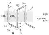
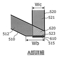
- FIG. 1 It is explanatory drawing of the coil shape in Example 1 of this invention. It is explanatory drawing of the coil shape in Example 1 of this invention. It is a detailed view of the part A in FIG. 1B.
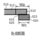
- FIG. 3 is a cross-sectional view taken along the line BB in FIG. 1B. It is a figure which shows the modification of the example shown in FIG. 1C. It is a figure which shows the other modification of the example shown in FIG. 1C. It is a figure which shows the modification of the example shown in FIG. 1D.
- FIG. 2 It is explanatory drawing of the coil shape in Example 1 of this invention. It is a detailed view of the part A in FIG. 2A.
- FIG. 2 is a cross-sectional view taken along the line BB in FIG. 2A.
- Example 1 of this invention It is explanatory drawing of the dimensional relation with the number of radial layers in Example 1 of this invention. It is explanatory drawing of the appearance of a coil in Example 1 of this invention. It is explanatory drawing of the coil shape in Example 2 of this invention. It is explanatory drawing of the coil shape in Example 2 of this invention. It is Example 3 of this invention, and is explanatory drawing of the vehicle to which this invention is applied.
- coil is defined as one volume of a hexagonal volume or one cycle of a wave winding.
- the definition of “coil” is defined as one volume of a hexagonal volume or one cycle of a wave winding.
- the coil is expressed as a coil with four turns, but in the following description, for the sake of simplicity, one coil (coil per turn) is basically targeted.
- each conductor is called a segment coil.
- the following description targets variable speed drive rotary electric machines such as automobiles and railroad vehicles, the effect of the present invention is not limited to this, and can be applied to all rotary electric machines including constant speed.
- the rotating machine may be an induction machine, a permanent magnet synchronous machine, a winding type synchronous machine, a synchronous reluctance rotating machine, or a switched reluctance rotating machine.
- an abduction type rotary electric machine may also be used.
- the material of the coil may be copper, aluminum, or other conductive material.
- the cross-sectional shape of the coil is described for a single square wire, the effect of the present invention is not limited to this, and a plurality of round wires or the like are aligned or molded to form a square shape. You may.
- Example 1 of the present invention will be described with reference to FIGS. 1A to 8.
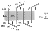
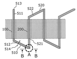
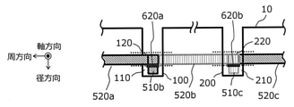
- 1A to 1G are explanatory views of the coil shape of the rotary electric machine according to the first embodiment of the present invention.
- 2A to 2C are explanatory views of a modified example of the coil shape of the rotary electric machine according to the first embodiment of the present invention.
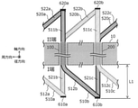
- 3A to 3C are explanatory views of the entire coil configuration according to the first embodiment of the present invention.
- 4A and 4B are explanatory views of the coil end length of the coil end 800 of the first embodiment of the present invention.
- 5A and 5B are explanatory views of the dimensional relationship of the coil end of the first embodiment of the present invention.
- 6A and 6B are explanatory views of the coil circumferential length of the first embodiment of the present invention.
- FIG. 7 is an explanatory diagram of the number of radial layers and the dimensional relationship according to the first embodiment of the present invention.
- FIG. 8 is an explanatory diagram of the appearance of the coil according to the first embodiment of the present invention.
- the stator core 10 is provided with an adduction type rotor (not shown) that is freely rotatably supported in the circumferential direction via a gap on the inner peripheral side in the radial direction.
- the stator core 10 has a plurality of slots 100, 200, in the circumferential direction. .. .. Has slots 100, 200 ,. .. .. Inside, there are a plurality of square wire segment coils, the first segment coil 510, the second segment coil 520 ,. .. .. (Hereinafter, it may be abbreviated as a coil)) is inserted and stored.
- the coils 510 and 520 are coated with an insulating film such as epoxy resin in order to secure insulation between the coils. Further, in order to secure insulation between the coils 510 and 520 and the stator core 10, the slots 100 and 200 are provided with insulating paper and an insulating resin bobbin.
- the coil 510 has an insertion portion inserted into the slot 100 and is formed linearly along the axial direction, and is connected to the first region portion 511 and in the circumferential direction.
- a second region portion 512 formed along the circumferential direction including the bent portion 512d, an end cross section 513 formed at the end of the first region portion 511, and an end formed at the end of the second region portion 512. It has a partial cross section of 515.
- the coil 520 has a first region portion 521 having an insertion portion into the slot 200 and formed linearly along the axial direction, and a portion connected to the first region portion 521 and bent in the circumferential direction.
- a second region portion 522 including and formed along the circumferential direction, an end cross section 523 formed at the end of the first region portion 521, and an end cross section 525 formed at the end of the second region portion 522.
- the preformed coils 510 and 520 are inserted from the I end and the II end, which are the axial ends, respectively.
- the second region portion end cross section 515 of the inserted coil 510 is the first region portion end cross section 523 of the coil 520.
- the coils 510 and 520 are electrically and mechanically connected by the linear conductive portion 610, which is arranged on the same cross section as the above.
- the second region portion end cross section 515 of the coil 510 is different from the vertical cross section 514 (shown in FIG. 1B) in the second region portion 512 of the coil 510.
- the linear conductive portion 610 is different from the conventional TIG welded portion in that it does not have a straight portion extending in the axial direction.
- Such a linear conductive portion 610 is realized by electron beam welding or laser welding, and as shown in the BB cross section of FIG. 1D, a welding wire extending in the circumferential direction when the coil end is viewed from the axial direction is formed. It is characterized by forming.
- the weld line extending in the circumferential direction is a linear conductive portion 610.
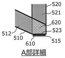
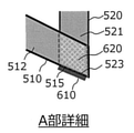
- the coils 510 and 520 may be electrically and mechanically connected by the planar conductive portion 620 shown in detail of the A portion in FIG. 1C.
- the planar conductive portion 620 is formed by contacting the radial inner peripheral surface of the second region portion 512 end of the coil 510 with the radial inner peripheral surface of the first region portion 521 end of the coil 520. Is a feature.
- the coil 510 and the coil 520 come into contact with each other in a state where the insulating film is peeled off or in a state where electrical conduction is ensured.
- a conductive member such as a conductive paste, a conductive sheet, or a conductive adhesive may be interposed between the coil 510 and the coil 520.
- at least one end of the coil 510 and the coil 520 may be subjected to metal plating in advance, and the conductivity may be improved by mediating the metal plating when forming the planar conductive portion 620.
- a material having a relatively low melting point such as zinc or tin is used as the above-mentioned metal plating material, and heat treatment is performed until the metal plating material is melted in the state shown in FIG. 1B to form a surface through the metal plating material.
- the conductive portion 620 may be connected not only electrically but also mechanically.
- planar conductive portion 620 and the linear conductive portion 610 may be provided at the same time.
- the shape of the second region end cross section 515 of the coil 510 may be formed so as to be different from the vertical cross section 514 by adjusting the cutting direction, cutting load, etc. when cutting the coil 510. It may be molded differently depending on other methods.
- end cross section 515 may be arranged on the same cross section as the first region end cross section 523 of the coil 520, and is not limited to the form shown in FIG. 1B, and may be any other form.
- the end cross section 523 of the coil 520 when the end cross section 523 of the coil 520 is different from the vertical cross section of the coil 520, the end cross section 515 of the coil 510 is on the same cross section as the end cross section 523 of the coil 520.
- the cutting direction may be adjusted so that it is arranged in.
- the coils 510 and 520 are electrically and mechanically connected by either or both of the linear conductive portion 610 and the planar conductive portion 620.
- the end cross section 515 of the coil 510 and the end cross section 523 of the coil 520 do not necessarily have to be in the same state in the circumferential direction, and are shown in FIG. 1G. It may be positioned so as to be offset in the circumferential direction.
- the length obtained by adding the circumferential width of the end cross section 515 to the circumferential width wc of the end cross section 523 of the coil 520 and subtracting the circumferential width of the overlapping portion of both is defined as wa. , Wc ⁇ wa.
- the coils 510 and 520 are electrically and mechanically connected by either or both of the linear conductive portion 610 and the planar conductive portion 620.
- insulation failure may occur due to damage to the insulating paper or the coil coating, or the bending angle or springback may vary. It is possible to solve problems such as welding defects.
- the connecting portion does not have a straight portion extending in the axial direction, it is possible to solve the problem that the axial length increases and the motor physique and the motor weight increase.
- FIGS. 2A to 2C The difference between the examples shown in FIGS. 1A to 1G and the examples shown in FIGS. 2A to 2C is the shape of the end cross section 515 of the coil 510.
- the circumferential width of the end cross section 515 of the coil 510 is wb, and wc ⁇ wb with respect to the circumferential width wc of the end cross section 523 of the coil 520. ..
- the slot 100 has a first layer 110, a second layer 120, a third layer 130, and a fourth layer 140 arranged in the radial direction of the rotary electric machine.
- the second region portion 512 of the first segment coil 510 appears on the first layer 110
- the first region portion end cross section 523 of the second segment coil 520 appears on the second layer 120
- the third layer 130 has a second region portion.
- the second region portion 532 of the three-segment coil 530 appears
- the first region portion end cross section 543 of the fourth segment coil 540 appears on the fourth layer 140.
- the coils 510 and 520 are electrically and mechanically connected by either or both of the linear conductive portion 610 and the planar conductive portion 620. If the above-mentioned form is secured, the end cross section 515 of the coil 510 and the end cross section 523 of the coil 520 are displaced by w1 in the circumferential direction as in the BB cross section shown in FIG. 2C. May be located.
- the coils 530 and 540 are electrically and mechanically connected by either or both of the linear conductive portion 630 and the planar conductive portion 640. If the above-mentioned form is secured, the end cross section 535 of the coil 530 and the end cross section 543 of the coil 540 are displaced by w2 in the circumferential direction as in the BB cross section shown in FIG. 2C. May be located.
- a layer short circuit can be avoided by providing an interlayer gap 400 between the coil 520 and the coil 530.
- a non-conductive and non-magnetic material such as an insulating paper, an insulating sheet, and an insulating resin may be arranged in the inter-layer gap 400.
- a metal material may be arranged in the inter-layer gap 400.
- FIGS. 3A, 3B and 3C are side views seen from the respective axial directions.
- the difference from the examples shown in FIGS. 1A to 1G is that the coils 510a, 510b, and 510c are arranged in the circumferential direction of the first layer 110, and the coils 520a, 520b, and 520c are arranged in the circumferential direction of the second layer 120. That is the point.
- the coil 510a and the coil 520b are electrically and mechanically connected by the linear conductive portion 610a
- the coil 510b and the coil 520c are electrically and mechanically connected by the linear conductive portion 610b.
- the second region portions 512a, 512b, 512c of the coils 510a, 510b, and 510c appear on the first layer 110
- the coils 520b and 520c appear on the second layer 120.
- the first region portion 521b and 521c appear.
- the coil 520a and the coil 510b are electrically and mechanically connected by the linear conductive portion 620a
- the coil 520b and the coil 510c are electrically and mechanically connected by the linear conductive portion 620b.
- the first region portions 511b and 511c of the coils 510b and 510c appear on the first layer 110 at the II end, which is the axial end, and on the second layer 120.
- the second region portions 522a, 522b, and 522c of the coils 520a, 520b, and 520c appear at the II end, which is the axial end portion.
- the coils 510a, 510b, and 510c are arranged in the first layer and the segment coils 520a, 520b, and 520c are arranged in the second layer, the coils do not move to different layers. ..
- the segment coil has only one bent portion between the first region portion and the second region portion, the problem that the bending step is only required once in coil forming and the processing cost increases is solved. be able to.
- the coil end portion may be electrically or mechanically connected by the planar conductive portion 620 (620a, 620b) instead of the linear conductive portion 610 (610a, 610b). You may use both.
- the form of the coil end portion is not limited to the form of FIGS. 3A to 3C, and may be the form of FIGS. 1A to 1G, FIGS. 2A to 2C, or other forms.
- FIG. 4B is a detailed view of part A shown in FIG. 4A.
- coils 510a and 510b are arranged in the circumferential direction of the first layer.
- the coil end length le increases as the number of straddling slots increases. That is, the larger the number of phases m, the number of slots for each pole of each phase q, and the winding span W / ⁇ p ( ⁇ 1), the greater the increase. Since an increase in the coil end length le leads to an increase in the motor physique and the motor weight, it is important to make the le as small as possible.
- the number of slots that the coil straddles is called "the number of layers in the axial direction Nz" and is defined as the following equation (1).
- Nz 6.
- the coil end length le increases as the number of axial layers Nz increases.
- the coil end length le can be formulated as in the following equation (2).
- wt the width of the stator teeth 20
- ws the slot width
- wc the coil width
- wi the distance between the coils at the coil end
- ⁇ the coil inclination angle with respect to the axial end surface of the stator core 10.
- the inclination ⁇ can also be expressed by the following equation (3) by using the dimensional relationship of the details of part A in FIG. 4B.
- the coil end length le and the coil inclination angle ⁇ are functions of ws, wt, and Nz.
- the ratio rw of the tooth width wt and the slot width ws is defined by the following equation (6).
- equations (4) and (5) can be expressed as the following equations (7) and (8).
- FIG. 5A shows the relationship between the left side of the above equation (9) and rw.
- the coil end length le can be reduced as the rw is increased.
- the coil end length le converges to a substantially constant value, and this tendency is the same in any Nz.
- the first slot 100 is composed of four layers, and the first layer 110, the second layer 120, the third layer 130, and the fourth layer 140 are arranged in order from the radial outer peripheral side.
- the point that the second slot 200 is also composed of four layers is the same.
- a first region portion 511a (not shown) of the first segment coil 510a is inserted into the first layer 110 of the slot 100, and a second region portion 512a is inserted into the coil end portion as shown in FIG. 6A.
- the second region end end cross section 515a appears.
- the first region portion end cross section 523b of the second segment coil 520b appears.
- the coil 510a and the coil 520b are electrically and mechanically connected by a linear conductive portion 610.
- a first region portion 531a (not shown) of the third segment coil 530a is inserted in the third layer 130 of the slot 100, and a two region portion is inserted in the coil end portion as shown in FIG. 6A.
- a 532a and a second region end cross section 535a appear.
- the first region portion end cross section 543b of the fourth segment coil 540b appears.
- the coil 530a and the coil 540b are electrically and mechanically connected by a linear conductive portion 630.
- FIG. 6A it is only necessary to discuss the coil arrangement, so the description of other coils is omitted.
- FIG. 6B shows the arrangement of the coils 510a and 520b when FIG. 6A is viewed from the radial outer peripheral side.
- the circumferential width of the end cross section 515a of the second region portion 512a of the coil 510a is wb, and wc ⁇ wb with respect to the circumferential width wc of the coil 520b.
- the second region portion 512a of the coil 510a is inclined by an angle ⁇ with respect to the axial end surface of the stator core 10.
- the right end of the end cross section 515a of the coil 510a and the right end of the end cross section 523b of the coil 520b are arranged so as to coincide with each other in the circumferential direction.
- the circumferential width of the linear conductive portion 610 is equivalent to the circumferential width wc of the coil 520b.
- the right end of the end cross section 535a of the coil 530a and the right end of the end cross section 543b of the coil 540b have one circumferential position. I haven't done it. Even in this state, it is important to maintain the circumferential width of the linear conductive portion 630 equal to the circumferential width wc of the coil 540b in order to suppress the contact resistance and the resistance variation of the coil connecting portion.
- the dimensional condition is that the circumferential width of the linear conductive portion is equivalent to the coil width wc at any coil connection portion regardless of the radial position in the slot. Was newly found.
- the maximum value of wb can be defined by the following equation (11) by using the dimensional relationship shown in FIG. 6B.
- the size of wb can be reduced by, for example, forming a shape like the details of part A shown in FIG. 2B, and the maximum is when the right end of the end cross section 515a has an acute angle as shown in FIG. 6B. be.
- the circumferential distance ⁇ r between the first slot 100 and the second slot 200 shown in FIG. 6A can be defined by the following equation (12).
- Equation (12) P is the number of poles, m is the number of phases, q is the number of slots for each phase, ⁇ p is the pole pitch, and W is the winding span.
- the circumferential length w ⁇ of the coil 510a of the first layer 110 shown in FIG. 6B is represented by the following equation (13) by using the dimensional relationship shown in FIG. 6A.
- the circumferential lengths w ⁇ 1 and w ⁇ 3 of the coil 510a of the first layer 110 and the coil 530a of the third layer 130 are equal to each other, so that the following equation (14) holds.
- the left end of the end cross section 535a of the coil 530a is the end portion of the coil 540b. It suffices if it is located on the left side of the left end of the cross section 543b, and it suffices if the following equation (15) is satisfied.
- the left side is the circumferential length from the left end in the circumferential direction of the coil 530a to the left end of the end cross section 535a
- the right side is the end cross section of the coil 540b starting from the left end in the circumferential direction of the coil 530a.
- the circumferential length to the left end of 543b is shown.
- the end cross section 540b is always within the range of the circumferential width wb of the end cross section 535a, so that the circumferential width of the linear conductive portion 630 is the circumference of the coil 540b. It can be maintained at the same level as the directional width wc, and it is possible to suppress contact resistance and resistance variation at the coil connection portion.
- the same type of coil can be used in multiple layers while suppressing contact resistance and resistance variation at the coil connection, eliminating the need to change the circumferential length of the coil for each layer. It is possible to solve the problem of increasing points.
- the upper limit of the number of radial layers Nr is a function of the number of poles P and the coil cross-sectional aspect ratio wh / wc.
- FIG. 7 is a graph showing the relationship between the number of radial layers Nr and wh / wc at an arbitrary number of poles P.
- FIG. 7 shows that any number of poles P can be selected as a design value as long as the number of radial layers Nr is smaller than the curve shown in the figure. That is, it can be seen that the range of selectable Nr becomes smaller as the aspect ratio wh / wc increases.
- Example 1 of the present invention the condition represented by the following equation (22) was found as the dimensional condition that can improve the degree of freedom in design.
- FIG. 8 is a diagram showing a plurality of segment coils inserted into a plurality of slots (not shown) arranged in the circumferential direction.
- each slot has four layers arranged in the radial direction.
- the second region portion 512 of the first segment coil 510 appears in the first layer
- the first region portion 521 of the second segment coil 520 appears in the second layer
- the third segment appears in the third layer.
- the second region portion 532 of the coil 530 appears
- the first region portion 541 of the fourth segment coil 540 appears on the fourth layer.
- the first region portion 511 of the first segment coil 510 appears in the first layer
- the second region portion 522 of the second segment coil 520 appears in the second layer
- the second region portion 522 appears in the third layer.
- the first region portion 531 of the third segment coil 530 appears
- the second region portion 542 of the fourth segment coil 540 appears on the fourth layer.
- the coil does not move to a different layer.
- the first embodiment of the present invention it is possible to realize a highly efficient and highly reliable method for manufacturing a rotary electric machine and a rotary electric machine without increasing the physique and cost.
- At least two of the plurality of square wire segment coils 510, 520, 530, and 540 arranged in the plurality of layers 110 to 140 can be configured to have the same shape.
- Example 2 Next, Example 2 of the present invention will be described with reference to FIGS. 9A and 9B.
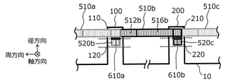
- FIGS. 3B and 3C are explanatory views of the coil shape in the second embodiment of the present invention, and the difference from the first embodiment is the shape of the coil end, which corresponds to FIGS. 3B and 3C showing the first embodiment. Is.
- the second region portion 512b is composed of a third region portion 516b whose thickness decreases in the direction away from the stator core 10 in the axial direction.
- the coil width of the second region portion 512b is w1 and the inclination angle with respect to the stator core axial end face is ⁇ 1
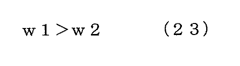
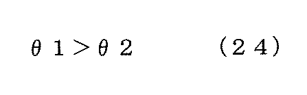
- the coil width w2 and the inclination angle ⁇ 2 of the third region portion 516b are the following equations (23) and (24), respectively. Satisfy the relationship.
- the coil strand may be formed by extrusion molding or drawing processing, or only the portion may be cut so as to have a width of w2.
- the angular bent portion is provided between the second region portion 512b and the third region portion 516b, a configuration in which the bent portion is smoothly bent on an arc may be used. Further, there may be two or more bent portions per segment coil.
- the same effect as that of the first embodiment can be obtained, and the axial length of the coil end can be reduced.
- the third region portion 516a, the third region portion 516c, the third region portion 526a, the third region portion 526b, and the third region portion 526c also have the same shape as the third region portion 516b. ..
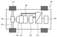
- FIG. 10 is an explanatory diagram of the vehicle 700 according to the third embodiment of the present invention.
- Example 1 or Example 2 of the present invention is applied to the rotary electric machines 751 and 752 shown in FIG.
- the vehicle 700 refers to, for example, a hybrid vehicle or a plug-in hybrid vehicle, and is equipped with an engine 760, rotary electric machines 751 and 752, and a battery 780.
- the battery 780 supplies DC power to the power conversion device 770 (inverter device) for driving.
- the power conversion device 770 converts the DC power from the battery 780 into AC power, and supplies the AC power to the rotary electric machines 751 and 752, respectively.
- the rotary electric machines 751 and 752 generate AC power according to the kinetic energy of the vehicle 700 and supply it to the power conversion device 770.
- the power conversion device 770 converts the AC power from the rotary electric machines 751 and 752 into DC power, and supplies this DC power to the battery 780.
- the rotational torque from the engine 760 and the rotary electric machines 751 and 752 is transmitted to the wheels 710 via the transmission 740, the differential gear 730 and the axle 720.
- 3rd segment coil 531 ... 1st region part, 532 ... 2nd region part, 535 ... end cross section, 540 ... 4th segment coil, 541 ... 1st region part, 542 ... 2nd region Part, 543 ... end cross section, 610, 630 ... linear conductive part, 620 ... planar conductive part, 700 ... vehicle, 710 ... wheel, 720 ... axle, 730 ... ⁇ ⁇ Differential gear, 740 ⁇ ⁇ ⁇ transmission, 751, 752 ⁇ ⁇ ⁇ rotating electric machine, 760 ⁇ ⁇ ⁇ engine, 770 ⁇ ⁇ ⁇ power converter, 780 ⁇ ⁇ ⁇ battery
Landscapes
- Engineering & Computer Science (AREA)
- Power Engineering (AREA)
- Transportation (AREA)
- Mechanical Engineering (AREA)
- Manufacturing & Machinery (AREA)
- Life Sciences & Earth Sciences (AREA)
- Sustainable Development (AREA)
- Sustainable Energy (AREA)
- Windings For Motors And Generators (AREA)
- Manufacture Of Motors, Generators (AREA)
Abstract
体格やコストの増加を招くことなく高効率で信頼性の高い回転電機が実現される。角線セグメントコイルのそれぞれは第1領域部と、第1領域部と繋がり、固定子コア10の周方向への屈曲部を含んで周方向に形成される第2領域部とを有し、複数の角線セグメントコイルのコイルエンドで隣り合う角線セグメントコイルの一対は一方の角線セグメントコイルの第1領域部と、他方の角線セグメントコイルの第2領域部が接続される導電部を有する。第2領域部は第1領域部の端部断面と同一面上に並ぶ導電部断面を有し、導電部断面は第2領域部のコイル鉛直断面とは異なる方向の断面である。複数のレイヤのそれぞれはコイルエンドを回転電機の軸方向から見た場合に第1領域部が軸方向端部に現れる第1レイヤと、第2領域部が軸方向端部に現れる第2レイヤとを有する。
Description
本発明は、鉄道車両、自動車、建機などに搭載される回転電機および回転電機の製造方法に関する。
近年、モータの高出力化を図るために大電流を流してトルクを増加する手法がとられている。大電流を流すためには、限られたモータ体積において導体断面積を大きくすることによって、導体で発生するジュール損(以下、銅損)を抑制することが重要である。
自動車などの駆動モータでは、導体断面積を向上するために角線を用いることで銅損の低減を図ってきた。
一般に、角線を用いる場合には、U字状コイルを固定子スロットに挿入し、そのあとに直線部を折り曲げる必要がある。この工程において、絶縁紙やコイル被膜の損傷により絶縁不良が起きたり、折り曲げ角度やスプリングバックのバラつきにより溶接不良が起きたりしやすく、信頼性確保について課題となっている。
特許文献1に記載の技術においては、この対策として、折り曲げが不要となるよう、コイル片を第1の直線部と第2の直線部、さらに曲げ部を介した第3の直線部で構成し、コイル片の端部同士を接合する方法が提案されている。また、隣り合うコイル片の直線部の端部同士をカシメ金具で仮固定している。
しかしながら、特許文献1の構成では、接続部分の第3の直線部によって軸方向長が増加するので、モータ体格およびモータ重量が増加する。
また、コイル片1個につき折り曲げ工数が2回必要であり加工コストが増加する課題がある。
また、第3の直線部の位置ズレを防止するためにカシメ金具が必要となり、部品点数、作業工数が増加してコストが増加する問題がある。
また、仮にカシメ金具を使用しない場合には、第3の直線部の位置ズレによって溶接不良を起こす課題が残る。
また、同一スロット内において径方向に複数のコイルレイヤを設ける場合、レイヤごとにコイルの周方向長さを変える必要があり、ここでも部品点数が増加する課題が生じる。 本発明の目的は、体格やコストの増加を招くことなく高効率で信頼性の高い回転電機および回転電機の製造法方法を実現することである。
上記目的を達成するために、本発明は、次のように構成される。
複数の角線セグメントコイルと、前記複数の角線セグメントコイルを収納するスロットを有する固定子コアと、を備える回転電機であって、前記スロットは、前記回転電機の径方向に並ぶ複数のレイヤを有し、前記複数の角線セグメントコイルのそれぞれは、前記スロット内に配置される挿入部を有し、かつ前記回転電機の軸方向に沿って直線状に形成される第1領域部と、前記第1領域部と繋がりかつ前記固定子コアの周方向への屈曲部を含んで周方向に沿って形成される第2領域部と、を有し、前記複数の角線セグメントコイルのコイルエンドにおいて隣り合う前記角線セグメントコイルの一対は、一方の前記角線セグメントコイルの前記第1領域部と、他方の前記角線セグメントコイルの前記第2領域部が接続される導電部を有し、前記導電部において、前記第2領域部は、前記第1領域部の端部断面と同一面上に並ぶ導電部断面を有し、かつ前記導電部断面は、前記第2領域部のコイル鉛直断面とは異なる方向の断面であり、前記複数のレイヤのそれぞれは、前記コイルエンドを前記回転電機の軸方向から見た場合に、前記第1領域部が軸方向端部に現れる第1レイヤと、前記第2領域部が軸方向端部に現れる第2レイヤと、を有する。
また、複数の角線セグメントコイルと、前記複数の角線セグメントコイルを収納するスロットを有する固定子コアとを備える回転電機の製造方法であって、前記スロットは、前記回転電機の径方向に並ぶ複数のレイヤを有し、前記複数の角線セグメントコイルのそれぞれは、前記スロット内に配置される挿入部を有し、かつ前記回転電機の軸方向に沿って直線状に第1領域部を形成し、前記第1領域部と繋がりかつ前記固定子コアの周方向への屈曲部を含んで周方向に沿って第2領域部を形成し、前記複数の角線セグメントコイルのコイルエンドにおいて隣り合う前記角線セグメントコイルの一対は、一方の前記角線セグメントコイルの前記第1領域部と、他方の前記角線セグメントコイルの前記第2領域部が接続される導電部を有し、前記導電部において、前記第2領域部は、前記第1領域部の端部断面と同一面上に並ぶ導電部断面を有し、かつ前記導電部断面は、前記第2領域部のコイル鉛直断面とは異なる方向の断面であり、前記複数のレイヤのそれぞれは、前記コイルエンドを前記回転電機の軸方向から見た場合に、前記第1領域部が軸方向端部に現れる第1レイヤと、前記第2領域部が軸方向端部に現れる第2レイヤと、を有する。
本発明によれば、体格やコストの増加を招くことなく高効率で信頼性の高い回転電機および回転電機の製造法方法を実現することができる。
上記した以外の課題、構成及び効果は、以下の実施形態の説明により明らかにされる。
以下、本発明の実施例について図面を参照して説明する。
以下の説明では、同一の構成要素には同一の記号を付してある。それらの名称および機能は同じであり、重複説明は避ける。本発明では、「コイル」の定義を亀甲巻の1巻、または波巻の1サイクルとする。例えば、コイルが4回巻き回された構成においては、4巻のコイルと表現するが、以下の説明では簡単のため基本的に1巻のコイル(1巻当りコイル)を対象とする。
また、1巻のコイルが複数の導体で構成される場合は、各導体をセグメントコイルと呼ぶ。また、以下の説明では自動車、鉄道車両など可変速駆動の回転電機を対象としているが、本発明の効果はこれに限定されるものではなく、一定速を含む回転電機全般に適用可能である。
また、回転機は誘導機でもよいし永久磁石同期機でもよいし巻線型同期機でもよいし、シンクロナスリラクタンス回転機でもよいし、スイッチトリラクタンス回転機でもよい。また、以下の説明では内転型の回転電機を対象としているが、外転型の回転電機でもよい。
また、コイルの材質は銅でも良いしアルミでもよいし、その他の導電材料でもよい。また、コイルの断面形状は単一の角線を対象として説明しているが、本発明の効果はこれに限定されるものではなく、複数の丸線等を整列または成形して角型に構成してもよい。
(実施例1)
以下、図1A乃至図8を用いて、本発明の実施例1について説明する。
以下、図1A乃至図8を用いて、本発明の実施例1について説明する。
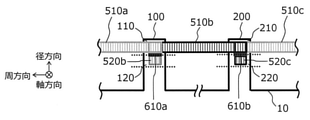
図1A~図1Gは本発明の実施例1における回転電機のコイル形状の説明図である。図2A~図2Cは、本発明の実施例1における回転電機のコイル形状の変形例の説明図である。図3A~図3Cは本発明の実施例1におけるコイル全体構成の説明図である。図4A及び図4Bは本発明の実施例1のコイルエンド800のコイルエンド長さの説明図である。図5A及び図5Bは本発明の実施例1のコイルエンドの寸法関係の説明図である。図6A及び図6Bは本発明の実施例1のコイル周方向長さの説明図である。図7は本発明の実施例1の径方向レイヤ数と寸法関係の説明図である。図8は本発明の実施例1のコイル外観の説明図である。
まず、本発明の実施例1におけるコイル形状について、図1A~図1Gを用いて説明する。
図1Aにおいて、固定子コア10は径方向内周側にギャップを介して、周方向に回転自由に支持された内転型回転子(図示していない)を具備する。固定子コア10は、周方向に複数のスロット100、200、...を有しており、スロット100、200、...内には、複数の角線セグメントコイルである第1セグメントコイル510、第2セグメントコイル520、...(以下、略してコイルと呼称する場合もある))が挿入され、収納される。
コイル510、520はコイル間の絶縁を確保するために、エポキシ樹脂等の絶縁皮膜でコーティングされる。また、コイル510、520と固定子コア10の間の絶縁確保のために、スロット100、200は絶縁紙や絶縁用樹脂ボビンを具備する。コイル510は、スロット100内に挿入されて配置される挿入部を有しかつ軸方向に沿って直線状に形成される第1領域部511と、第1領域部511と繋がりかつ周方向への屈曲部512dを含んで周方向に沿って形成される第2領域部512と、第1領域部511の終端に形成される端部断面513と、第2領域部512の終端に形成される端部断面515とを有する。
同様に、コイル520は、スロット200への挿入部を有しかつ軸方向に沿って直線状に形成される第1領域部521と、第1領域部521と繋がりかつ周方向への屈曲部を含んで周方向に沿って形成される第2領域部522と、第1領域部521の終端に形成される端部断面523と、第2領域部522の終端に形成される端部断面525とを有する。
図1Aに示すように、予め成形したコイル510、520をそれぞれ軸方向端部であるI端、II端からそれぞれ挿入する。このとき、図1Bに示す破線で囲んだA部の詳細を示す図1Cのように、挿入されたコイル510の第2領域部端部断面515は、コイル520の第1領域部端部断面523と同一断面上に配置され、線状導電部610によってコイル510と520が電気的・機械的に接続される。
このとき、コイル510の第2領域部端部断面515は、コイル510の第2領域部512における鉛直断面514(図1Bに示す)とは異なる。また、線状導電部610は、軸方向に延びる直線部を有していない点で従来のTIG溶接部とは異なる。このような線状導電部610は、電子ビーム溶接やレーザー溶接によって実現され、図1DのB-B断面に示すように、コイルエンドを軸方向から見た場合に、周方向に延びる溶接線を形成することが特徴である。周方向に延びる溶接線とは、線状導電部610のことである。
線状導電部610の代わりに、又は線状導電部610と共に、図1CのA部詳細に示す面状導電部620によってコイル510と520を電気的・機械的に接続してもよい。面状導電部620は、コイル510の第2領域部512端部の径方向内周面と、コイル520の第1領域部521端部の径方向外周面とを接触させて形成している点が特徴である。
この場合においても、軸方向に延びる直線部を有していない点で従来のTIG溶接部とは異なる。面状導電部620において、コイル510とコイル520は絶縁皮膜を剥離した状態で、または電気導通を確保した状態で互いに接触する。コイル510とコイル520との間には、導電性ペースト、導電性シート、導電性接着剤などの導電性部材を介してもよい。そのほかにも、コイル510とコイル520の少なくとも一方の端部に予め金属メッキ処理を施して、面状導電部620を形成する際に金属メッキを介すことで導電性を向上させても良い。
さらに、前述の金属メッキ材として亜鉛やスズなど比較的融点の低い材料を使用し、図1Bに示した状態で金属メッキ材が溶融するまで加熱処理することで、金属メッキ材を介して面状導電部620を電気的のみならず機械的に接続しても良い。
また、面状導電部620と線状導電部610とを同時に設けても良い。
ここで、コイル510の第2領域部端部断面515の形状は、コイル510を切断するときの切断方向や切断荷重等を調整することで鉛直断面514と異なるように成形してもよいし、その他の方法によって異なるように成形してもよい。
また、端部断面515はコイル520の第1領域部端部断面523と同一断面上に配置されていればよく、図1Bに示す形態に限らず、その他のどのような形態でもよい。
例えば、図1E、図1Fに示すように、コイル520の端部断面523がコイル520の鉛直断面と異なる場合においては、コイル510の端部断面515がコイル520の端部断面523と同一断面上に配置されるように切断方向を調整すればよい。この場合においても、コイル510と520は線状導電部610と面状導電部620のいずれかまたは両方によって電気的・機械的に接続される。
前述のような形態が確保されているのであれば、コイル510の端部断面515とコイル520の端部断面523とは、必ずしも周方向位置が一致した状態でなくてもよく、図1Gに示すように周方向にずれて位置してもよい。図1Gでは、コイル520の端部断面523の周方向幅wcに対して、端部断面515の周方向幅を加算し、かつ両者の重なり部分の周方向幅を減算した長さをwaとしており、wc<waとなっている。この状態においても、コイル510と520は線状導電部610と面状導電部620のいずれかまたは両方によって電気的・機械的に接続される。
したがって、コイルの位置ズレを防止する必要がなくなるため、カシメ金具等による位置合わせが不要となる。
以上のように、本発明によれば、予め成形したコイルを固定子コア10に挿入するだけでよいので、絶縁紙やコイル被膜の損傷により絶縁不良が起きたり、折り曲げ角度やスプリングバックのバラつきにより溶接不良が起きたりする課題を解決することができる。
また、接続部分には軸方向に延びる直線部が存在しないため、軸方向長が増加してモータ体格およびモータ重量が増加する課題を解決することができる。
また、コイル当りの折り曲げ工数が1回で良いので、コイル成形において加工コストが増加する課題を解決することができる。
また、接続部分での位置ズレ防止用のカシメ金具が不要となるため、部品点数、作業工数が増加してコストが増加する課題を解決することができる。
続いて、本発明の実施例1における変形例のコイル形状について図2A~図2Cを用いて説明する。図1A~図1Gに示した例と図2A~図2Cに示した例との違いは、コイル510の端部断面515の形状である。
図2BのA部詳細に示すように、コイル510の端部断面515の周方向幅はwbであり、コイル520の端部断面523の周方向幅wcに対して、wc<wbとなっている。
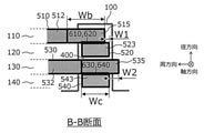
一方、図2AのB-B断面を示す図2Cにおいて、スロット100は、回転電機径方向に並ぶ第1レイヤ110、第2レイヤ120、第3レイヤ130、第4レイヤ140を有する。
第1レイヤ110には第1セグメントコイル510の第2領域部512が現れ、第2レイヤ120には第2セグメントコイル520の第1領域部端部断面523が現れ、第3レイヤ130には第3セグメントコイル530(図8に示す)の第2領域部532が現れ、第4レイヤ140には第4セグメントコイル540(図8に示す)の第1領域部端部断面543が現れる。
コイル510と520は、線状導電部610と面状導電部620のいずれかまたは両方によって電気的・機械的に接続される。前述のような形態が確保されているのであれば、コイル510の端部断面515とコイル520の端部断面523とは、図2Cに示すB-B断面のように、周方向にw1だけずれて位置してもよい。
同様にして、コイル530と540は、線状導電部630と面状導電部640のいずれかまたは両方によって電気的・機械的に接続される。前述のような形態が確保されているのであれば、コイル530の端部断面535とコイル540の端部断面543とは、図2Cに示すB-B断面のように、周方向にw2だけずれて位置してもよい。
なお、コイル520とコイル530との間にはレイヤ間空隙400を設けることでレイヤショートを回避することができる。レイヤ間空隙400には絶縁紙、絶縁シート、絶縁樹脂など非導電性かつ非磁性の材料を配置しても良い。
また、コイル520、530の絶縁皮膜が十分な絶縁耐力を有しているのであれば、レイヤ間空隙400には金属材料を配置しても良い。
このように、コイル510の端部断面515とコイル520の端部断面523とがwc<wbの関係となるように構成することで、コイルの位置ズレの発生を厳格に防止する必要がなくなるため、カシメ金具等による位置合わせが不要となる。
また、コイル510、520と異なるレイヤに配置されるコイル530、540の接続においても、コイルの位置ズレの発生を厳格に防止する必要がなくなるため、カシメ金具等による位置合わせが不要となる。
また、同一種類のコイルを複数のレイヤで兼用できるので、レイヤごとにコイルの周方向長さを変える必要が無くなり、部品点数が増加する課題を解決することができる。
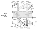
次に、本発明の実施例1におけるコイルの全体構造について図3A、図3B及び図3Cを用いて説明する。図3Bは径方向外周側から見た平面図、図3A及び図3Cは、それぞれの軸方向から見た側面図である。図1A~図1Gに示した例との違いは、第1レイヤ110の周方向にコイル510a、510b、510cが並んでおり、第2レイヤ120の周方向にコイル520a、520b、520cが並んでいる点である。
I端において、コイル510aとコイル520bとは線状導電部610aによって、コイル510bとコイル520cとは線状導電部610bによってそれぞれ電気的・機械的に接続される。I端のコイルエンドを軸方向から見た場合に、第1レイヤ110にはコイル510a、510b、510cの第2領域部512a、512b、512cが現れ、第2レイヤ120にはコイル520b、520cの第1領域部521b、521cが現れる。
一方、II端において、コイル520aとコイル510bとは線状導電部620aによって、コイル520bとコイル510cとは線状導電部620bによってそれぞれ電気的・機械的に接続される。II端のコイルエンドを軸方向から見た場合に、第1レイヤ110にはコイル510b、510cの第1領域部511b、511cが軸方向端部であるII端に現れ、第2レイヤ120にはコイル520a、520b、520cの第2領域部522a、522b、522cが軸方向端部であるII端に現れる。
本発明のコイル構成では、このようにセグメントコイル510a、510b、510cは第1レイヤに、セグメントコイル520a、520b、520cは第2レイヤに配置されるため、コイルが異なるレイヤに移動することが無い。
すなわち、セグメントコイルは第1領域部と第2領域部との間に1箇所の屈曲部を有するだけなので、コイル成形において曲げ工程が1回のみで良くなり、加工コストが増加する課題を解決することができる。
なお、図3A~図3Cにおいて、コイルエンド部は線状導電部610(610a、610b)の代わりに面状導電部620(620a、620b)で電気的・機械的に接続されても良いし、その両方を使用しても良い。
また、コイル端部の形態に関しても、図3A~図3Cの形態に限定されるものではなく、図1A~図1G、図2A~図2Cまたはその他の形態でも良い。
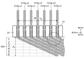
続いて、本発明におけるコイルエンド長さについて図4A及び図4Bを用いて説明する。図4Bは、図4Aに示したA部の詳細図である。
図4A及び図4Bにおいて、第1レイヤの周方向にはコイル510a、510bが並んでいる。コイル510aは、固定子ティース20の間に配置された6スロットのコイルからなり、相数m=3、毎相毎極スロット数q=2、極ピッチτpに対して巻線スパンW=τpとなる分布巻の巻線配置である。
図4Aの左から順にスロット番号1~7を割り当てると、スロット1に挿入されたコイル510a、u1は、5つスロットを跨り、スロット7の第2レイヤに挿入されたコイル520b、u1(図示していない)と接続される。
同様に、スロット2、3、...に挿入されたコイル510a、u2、コイル510a、v1、...はそれぞれ5つスロットを跨り、スロット8、9、...の第2レイヤに挿入されたコイル520b、u2、コイル520b、v1、...(図示していない)に接続される。
図4Aからわかるように、いずれのコイルも同一形状を有しており、コイルエンドの軸方向長さ(以下、略してコイルエンド長と呼称)leも同一となる。コイルエンド長leは跨るスロット数が多いほど大きくなる。すなわち、相数m、毎相毎極スロット数q、巻線スパンW/τp(≦1)が大きいほど増加する。コイルエンド長leの増加はモータ体格およびモータ重量の増加を招くため、leを可能な限り小さくすることが重要である。
そこで、本発明では、以下に示すように、コイルエンド長さleを定式化した上で、コイルエンド長さleが最小化される寸法条件を新たに見出した。
まず、コイルエンド長leの定式化にあたって、コイルが跨るスロット数を「軸方向レイヤ数Nz」と呼称し、次式(1)のように定義する。

図4Aに示した例ではNz=6である。図4Aからも明らかなように軸方向レイヤ数Nzの増加に伴いコイルエンド長leは増加する。
図4BのA部詳細に示す寸法関係を用いることで、コイルエンド長leは次式(2)のように定式化できる。

ただし、wt:固定子ティース20の幅、ws:スロット幅、wc:コイル幅、wi:コイルエンドにおけるコイル同士の間隔、β:固定子コア10の軸方向端面に対するコイル傾斜角である。
また、傾きβに関しても図4BのA部詳細の寸法関係を用いることで、次式(3)で表せる。

一般的な回転電機においては、Wc≒Ws、Wc≫Wiの近似が成り立つので、これを上記式(2)、(3)に適用すると次式(4)、(5)が得られる。


上記式(4)、(5)より、コイルエンド長le、コイル傾斜角βは、ws、wt、Nzの関数であることがわかる。ここで、ティース幅wtとスロット幅wsの比rwを次式(6)のように定義する。

式(6)を用いると式(4)、(5)は次式(7)、(8)のように表すことができる。


式(7)、(8)において、任意の軸方向レイヤ数Nzに対してrw=0.1(ティース幅wtがスロット幅wsの1/10)としたときのコイルエンド長leを基準値とすると、rwの変化に対してコイルエンド長le(rw)は次式(9)で表される。

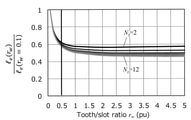
上記式(9)の左辺とrwの関係を図5Aに示す。代表例としてNz=2、Nz=12の曲線のみ指し示しており、両者の曲線の間に描かれているNz=3、4、...11の曲線に関しては指示を省略した。
図5Aより、rwを大きくするほどコイルエンド長leを低減できることがわかる。ただし、rw>0.5(ティース幅wtがスロット幅wsの半分以上)の範囲においては、コイルエンド長leはほぼ一定値に収束しており、この傾向はいずれのNzにおいても同様である。
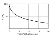
一方で、式(8)より得られるβとrwの関係を図5Bに示す。βはrwのみの関数なのでNzとは無関係である。
図5Bより、βはrwの増加に伴い減少しており、これがコイルエンド長leの低減に寄与していることがわかる。ただし、rw>10(ティース幅wtがスロット幅wsの10倍以上)の範囲においてはβの低減傾向がほぼ収束しており、コイルエンド長低減に対して大きな効果が見込めない。
以上より、本発明ではコイルエンド長leを最小化できる寸法条件として以下を見出した。

続いて、本発明の実施例1におけるコイルエンド周方向長さについて図6A及び図6Bを用いて説明する。
図6Aにおいて、第1スロット100は4つのレイヤで構成され、径方向外周側から順に第1レイヤ110、第2レイヤ120、第3レイヤ130、第4レイヤ140が配置されている。第2スロット200においても4つレイヤで構成される点は同様である。スロット100の第1レイヤ110には第1セグメントコイル510aの第1領域部511a(図示していない)が挿入されており、コイルエンド部には図6Aに示すように、第2領域部512aと第2領域部端部断面515aが現れる。
第2スロット200の第2レイヤには第2セグメントコイル520bの第1領域部端部断面523bが現れる。コイル510aとコイル520bとは線状導電部610によって電気的・機械的に接続される。
同様に、スロット100の第3レイヤ130には第3セグメントコイル530aの第1領域部531a(図示していない)が挿入されており、コイルエンド部には図6Aに示すように、2領域部532aと第2領域部端部断面535aが現れる。
第2スロット200の第4レイヤには第4セグメントコイル540bの第1領域部端部断面543bが現れる。コイル530aとコイル540bとは線状導電部630によって電気的・機械的に接続される。
なお、図6Aでは上記コイル配置に関して議論できればよいので、その他のコイルに関しては記載を省略している。
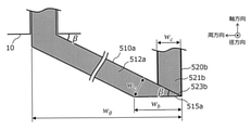
図6Aを径方向外周側から見たときのコイル510a、520bの配置を図6Bに示す。図6Bにおいて、コイル510aの第2領域部512aの端部断面515aの周方向幅はwbであり、コイル520bの周方向幅wcに対してwc<wbとなっている。コイル510aの第2領域部512aは固定子コア10の軸方向端面に対して角度βだけ傾斜している。
図6A及び図6Bに示すように、コイル510aの端部断面515aの右端と、コイル520bの端部断面523bの右端とは、周方向位置が一致するように配置されている。このとき、線状導電部610の周方向幅はコイル520bの周方向幅wcと同等である。
一方で、コイル530aとコイル510aとは同一形状であるので、図6Aに示すようにコイル530aの端部断面535aの右端と、コイル540bの端部断面543bの右端とは、周方向位置が一致していない。この状態においても、コイル接続部の接触抵抗抑制と抵抗バラツキ抑制を図るためには、線状導電部630の周方向幅をコイル540bの周方向幅wcと同等に維持することが重要である。
そこで、本発明の実施例1では、以下に示すようにスロット内の径方向位置に依らず、いずれのコイル接続部においても線状導電部の周方向幅がコイル幅wcと同等となる寸法条件を新たに見出した。
まず、図6Bに示す寸法関係を用いることでwbの最大値は次式(11)のように定義できる。

wbの大きさは、例えば図2Bに示したA部詳細のような形状とすることで低減可能であり、最大となるのは図6Bに示すように端部断面515a右端が鋭角となるときである。
また、図6Aに示す第1スロット100と第2スロット200の周方向距離θrは次式(12)のように定義できる。

ただし、式(12)において、Pは極数、mは相数、qは毎相毎極スロット数、τpは極ピッチ、Wは巻線スパンである。
図6Bに示す第1レイヤ110のコイル510aの周方向長さwθは、図6Aに示す寸法関係を用いることで、次式(13)で表される。

ただし、式(13)において、Rsはスロット半径、whはコイル厚、wcはコイル幅である。
本発明の実施例1では、第1レイヤ110のコイル510a、第3レイヤ130のコイル530aそれぞれの周方向長さwθ1、wθ3を同等とするので次式(14)が成り立つ。

この場合、第2スロット200において、線状導電部630の周方向幅をコイル540bの周方向幅wcと同等に維持するためには、コイル530aの端部断面535aの左端がコイル540bの端部断面543b左端よりも左側に位置すれば良く、次式(15)を満足していれば良い。

上記式(15)において、左辺はコイル530aの周方向左端を起点として端部断面535aの左端までの周方向長さであり、右辺はコイル530aの周方向左端を起点としてコイル540bの端部断面543bの左端までの周方向長さを示している。
式(15)の関係が満足されれば、端部断面535aの周方向幅wbの範囲に端部断面540bが必ず収まる構成となるので、線状導電部630の周方向幅をコイル540bの周方向幅wcと同等に維持することができ、コイル接続部における接触抵抗の抑制と抵抗バラつきの抑制とを実現できる。
式(15)に式(13)を代入し、かつ径方向レイヤ数Nrの場合に一般化すると次式(16)が得られる。

式(16)をwbについて整理すると次式(17)を得る。

式(11)、(12)及び(16)より、スロット内の径方向位置に依らず、いずれのコイル接続部においても線状導電部の周方向幅がコイル幅wcと同等となる寸法条件は次式(18)のように定義できる。

これにより、コイル接続部における接触抵抗の抑制と抵抗バラつきの抑制を実現しつつ、同一種類のコイルを複数のレイヤで兼用できるので、レイヤごとにコイルの周方向長さを変える必要が無くなり、部品点数が増加する課題を解決することができる。
続いて、以下では、設計自由度の向上を目的として、コイル断面アスペクト比wh/wc(コイル厚:コイル幅の比)の最適条件を新たに見出す。
まず、上記式(18)において、各辺をコイル幅wcで除算すると、次式(19)が得られる。

上記式(6)、(8)及び(10)と、図5Bより、本発明の実施例1においては、ティース幅wtとスロット幅wsの比rwが、上限値(rw=10)をとるときにβは最小値(β=0.091rad=5.2deg.)となる。
このとき、式(19)の右辺1/sinβは最大値の11となる。したがって、式(19)の左辺に関しては次式(20)が成り立つ。

上記式(20)を径方向レイヤ数Nrについて整理すると次式(21)が得られる。

上記式(21)からわかるように、径方向レイヤ数Nrの上限値は、極数P、コイル断面アスペクト比wh/wcの関数となる。図7は、任意の極数Pにおける径方向レイヤ数Nrとwh/wcの関係を示すグラフである。図7では代表例として極数P=2、4、8、16、32、64の場合を示す。
図7において、任意の極数Pにおいて、図示される曲線よりも小さい径方向レイヤ数Nrであれば、設計値として選択可能であることを示している。すなわち、アスペクト比wh/wcの増加に伴い、選択可能なNrの範囲が小さくなることがわかる。
また、極数Pが小さくなるほど選択可能なNrの範囲が小さくなることがわかる。
一般に、モータ設計においては様々な顧客ニーズ(ここでは特に電圧・電流の仕様)に対応するために、径方向レイヤ数Nrの調整が重要となる。したがって、径方向レイヤ数Nrの上限値を高い水準に設定し、設計自由度を高めることが望ましい。
この観点で図7を見ると、アスペクト比wh/wc>1の範囲においては径方向レイヤ数Nrが下限値にほぼ収束しており、設計自由度が低い状態となっている。
以上より、本発明の実施例1では設計自由度を向上できる寸法条件として次式(22)で表される条件を見出した。
以上より、本発明の実施例1では設計自由度を向上できる寸法条件として次式(22)で表される条件を見出した。

本実施例1の最後に、本発明の実施例1におけるコイル外観について図8を用いて説明する。
図8は周方向に並ぶ複数のスロット(図示していない)に挿入された複数のセグメントコイルを示す図である。
図8において、各スロットは径方向に並ぶ4つのレイヤを有する。I端において、第1レイヤには第1セグメントコイル510の第2領域部512が現れ、第2レイヤには第2セグメントコイル520の第1領域部521が現れ、第3レイヤには第3セグメントコイル530の第2領域部532が現れ、第4レイヤには第4セグメントコイル540の第1領域部541が現れる。一方で、II端において、第1レイヤには第1セグメントコイル510の第1領域部511が現れ、第2レイヤには第2セグメントコイル520の第2領域部522が現れ、第3レイヤには第3セグメントコイル530の第1領域部531が現れ、第4レイヤには第4セグメントコイル540の第2領域部542が現れる。
このように、本発明の実施例1の構成においては、コイルが異なるレイヤに移動することが無い。また、コイルをスロットに挿入した後の折り曲げ加工等の工程が無い。このため、極めて容易にコイル組立作業を実施することができる。
つまり、本発明の実施例1によれば、体格やコストの増加を招くことなく高効率で信頼性の高い回転電機および回転電機の製造法方法を実現することができる。
なお、複数のレイヤ110~140に配置された複数の角線セグメントコイル510、520、530、540のうち少なくとも2つが、同一形状を有するように構成することができる。
(実施例2)
次に、図9A及び図9Bを用いて本発明の実施例2について説明する。
次に、図9A及び図9Bを用いて本発明の実施例2について説明する。
図9A及び図9Bは、本発明の実施例2におけるコイル形状の説明図であり、実施例1との違いはコイルエンドの形状であり、実施例1を示す図3B及び図3Cに対応する図である。
図9A及び図9Bのコイル510bに着目すると、第2領域部512bは固定子コア10から軸方向に遠ざかる方向に沿って厚みが小さくなる第3領域部516bで構成される。第2領域部512bのコイル幅をw1、固定子コア軸方向端面に対する傾斜角をθ1とするとき、第3領域部516bのコイル幅w2、傾斜角θ2はそれぞれ次式(23)及び(24)の関係を満たす。
その他のコイルについても同様の構成である。
このような構成によって、コイルエンドの軸方向長さを小さくすることができ、図9Aに示すL2は図3Bに示すL1よりも小さくなる。
第3領域部516bの加工方法としては、コイル素線を押出成形や引抜き加工で成形しても良いし、当該部のみw2の幅となるように切削しても良い。また、図9では第2領域部512bと第3領域部516bの間に角状の屈曲部を設けているが、円弧上に滑らかに屈曲する構成でも良い。また、前記屈曲部は1つのセグメントコイルにつき2か所以上あっても良い。
実施例2によれば、実施例1と同様な効果を得ることができる他、コイルエンドの軸方向長さを小さくすることができる。
なお、図9Aにおいて、第3領域部516a、第3領域部516c、第3領域部526a、第3領域部526b、第3領域部526cも、第3領域部516bと同様な形状となっている。
(実施例3)
次に、図10を用いて本発明の実施例3について説明する。図10は本発明の実施例3における車両700の説明図である。
次に、図10を用いて本発明の実施例3について説明する。図10は本発明の実施例3における車両700の説明図である。
図10に示す回転電機751、752に本発明の実施例1又は実施例2が適用される。車両700は例えばハイブリッド自動車、プラグインハイブリッド自動車を指し、エンジン760と回転電機751、752と、バッテリ780とが搭載されている。
バッテリ780は、回転電機751、752を駆動する場合、駆動用の電力変換装置770(インバータ装置)に直流電力を供給する。電力変換装置770は、バッテリ780からの直流電力を交流電力に変換して、この交流電力を回転電機751、752にそれぞれ供給する。
また、回生走行時には、回転電機751、752が車両700の運動エネルギーに応じて交流電力を発生して電力変換装置770に供給する。電力変換装置770は、回転電機751、752からの交流電力を直流電力に変換し、この直流電力をバッテリ780に供給する。
エンジン760および回転電機751、752による回転トルクは、変速機740、デファレンシャルギア730および車軸720を介して車輪710に伝達される。
一般に、自動車には坂道発進での低速大トルクや、高速道路での高速低トルク、街乗りでの中速中トルクなど、広い運転範囲が要求される。このような広い運転範囲において、回転電機751、752では高効率な運転が可能となる。加えて、熱損失が軽減されるので、車両700の安全性向上や長寿命化が可能になる。また、車両700の航続距離を延ばすことが可能になる。
なお、エンジン760を備えず、回転電機751、752の動力だけで駆動される電気自動車においても、本発明の実施例1又は実施例2による回転電機を適用することにより同様の効果が得られる。
10・・・固定子コア、20・・・固定子ティース、100・・・第1スロット、110・・・第1レイヤ、120・・・第2レイヤ、130・・・第3レイヤ、140・・・第4レイヤ、200・・・第2スロット、400・・・レイヤ間空隙、510・・・第1セグメントコイル、511・・・第1領域部、512・・・第2領域部、512d・・・屈曲部、513・・・端部断面、514・・・鉛直断面、515・・・端部断面、516b・・・第3領域部、520・・・第2セグメントコイル、521・・・第1領域部、522・・・第2領域部、523・・・端部断面、525・・・端部断面、526a・・・第3領域部、530・・・第3セグメントコイル、531・・・第1領域部、532・・・第2領域部、535・・・端部断面、540・・・第4セグメントコイル、541・・・第1領域部、542・・・第2領域部、543・・・端部断面、610、630・・・線状導電部、620・・・面状導電部、700・・・車両、710・・・車輪、720・・・車軸、730・・・デファレンシャルギア、740・・・変速機、751、752・・・回転電機、760・・・エンジン、770・・・電力変換装置、780・・・バッテリ
Claims (12)
- 複数の角線セグメントコイルと、前記複数の角線セグメントコイルを収納するスロットを有する固定子コアと、を備える回転電機であって、
前記スロットは、前記回転電機の径方向に並ぶ複数のレイヤを有し、
前記複数の角線セグメントコイルのそれぞれは、前記スロット内に配置される挿入部を有し、かつ前記回転電機の軸方向に沿って直線状に形成される第1領域部と、前記第1領域部と繋がりかつ前記固定子コアの周方向への屈曲部を含んで周方向に沿って形成される第2領域部と、を有し、
前記複数の角線セグメントコイルのコイルエンドにおいて隣り合う前記角線セグメントコイルの一対は、一方の前記角線セグメントコイルの前記第1領域部と、他方の前記角線セグメントコイルの前記第2領域部が接続される導電部を有し、
前記導電部において、前記第2領域部は、前記第1領域部の端部断面と同一面上に並ぶ導電部断面を有し、かつ前記導電部断面は、前記第2領域部のコイル鉛直断面とは異なる方向の断面であり、
前記複数のレイヤのそれぞれは、前記コイルエンドを前記回転電機の軸方向から見た場合に、前記第1領域部が軸方向端部に現れる第1レイヤと、前記第2領域部が軸方向端部に現れる第2レイヤと、を有することを特徴とする回転電機。 - 請求項1記載の回転電機において、
前記導電部は、前記コイルエンドを前記回転電機の軸方向から見た場合に、前記回転電機の周方向に延びる溶接線、及び前記第2領域部の径方向面と前記第1領域部の径方向面との接触によって形成されるか、前記溶接線か、前記第2領域部の径方向面と前記第1領域部の前記径方向面との接触のうちのいずれかで形成されることを特徴とする回転電機。 - 請求項1に記載の回転電機において、
前記導電部は、
前記第1領域部の端部断面は、wcの大きさの周方向幅を有し、
前記wcと、前記第2領域部の端部断面の周方向幅と、を加算し、かつ前記第1領域部の端部断面と前記第2領域部の端部断面とが径方向に重なる部分の周方向幅を減算した長さをwaとして、wc<waとなるか、または
前記第2領域部の端部断面は、wbの大きさの周方向幅を有し、
前記wcに対して、wc<wbとなるか、またはwc<waかつwc<wbとなることを特徴とする回転電機。 - 請求項1に記載の回転電機において、
前記複数のレイヤに配置された前記複数の角線セグメントコイルのうち少なくとも2つは、同一形状を有することを特徴とする回転電機。 - 請求項1に記載の回転電機において、
前記固定子コアは前記回転電機の周方向に並ぶ複数の固定子ティースを有し、
前記固定子ティースは、周方向幅wtを有し、
前記スロットは、周方向幅wsを有し、
前記周方向幅wtと前記周方向幅wsの間には、
0.5≦(wt/ws)≦10
の関係が成り立つことを特徴とする回転電機。 - 請求項1に記載の回転電機において、
前記回転電機は、極数P、極ピッチτp、巻線スパンW、径方向レイヤ数Nr、コイル厚wh、コイル幅wc、前記固定子コアの軸方向端面に対するコイル傾斜角βであり、前記第2領域部の端部断面は、wbの大きさの周方向幅を有し、
前記wbとの間には、
(W・2π)/(τp・P)・(Nr-2)・wh+wc≦wb≦wc/sinβ
の関係が成り立つことを特徴とする回転電機。 - 請求項6に記載の回転電機において、
前記径方向レイヤ数Nrは、
Nr<((10・P)/((W/τp)・2π))・(1/(wh/wc))+2
の関係が成り立つことを特徴とする回転電機。 - 請求項1に記載の回転電機において、
前記回転電機は、コイル厚wh、コイル幅wcであり、
前記コイル厚whと前記コイル幅wcとの間には、
0<(wh/wc)≦1
の関係が成り立つことを特徴とする回転電機。 - 請求項1に記載の回転電機において、
前記第2領域部は、前記固定子コアから前記回転電機の軸方向に遠ざかる方向に沿ってコイル幅が小さくなる第3領域部を有することを特徴とする回転電機。 - 請求項9に記載の回転電機において、
前記第2領域部は、前記固定子コアの軸方向端面に対して傾斜角θ1だけ傾き、
前記第3領域部は、前記固定子コアの軸方向端面に対して傾斜角θ2だけ傾き、
前記傾斜角θ1と前記傾斜角θ2は、傾斜角θ1>傾斜角θ2の関係を満たすことを特徴とする回転電機。 - 請求項1に記載の回転電機において、
回転電機と、バッテリと、前記バッテリの直流電力を交流電力に変換して、前記交流電力を前記回転電機に供給する電力変換装置と、を備え、前記回転電機のトルクが変速機を介して車輪に伝達される車両の前記回転電機に用いられることを特徴とする回転電機。 - 複数の角線セグメントコイルと、前記複数の角線セグメントコイルを収納するスロットを有する固定子コアとを備える回転電機の製造方法であって、
前記スロットは、前記回転電機の径方向に並ぶ複数のレイヤを有し、
前記複数の角線セグメントコイルのそれぞれは、前記スロット内に配置される挿入部を有し、かつ前記回転電機の軸方向に沿って直線状に第1領域部を形成し、
前記第1領域部と繋がりかつ前記固定子コアの周方向への屈曲部を含んで周方向に沿って第2領域部を形成し、
前記複数の角線セグメントコイルのコイルエンドにおいて隣り合う前記角線セグメントコイルの一対は、一方の前記角線セグメントコイルの前記第1領域部と、他方の前記角線セグメントコイルの前記第2領域部が接続される導電部を有し、
前記導電部において、前記第2領域部は、前記第1領域部の端部断面と同一面上に並ぶ導電部断面を有し、かつ前記導電部断面は、前記第2領域部のコイル鉛直断面とは異なる方向の断面であり、
前記複数のレイヤのそれぞれは、前記コイルエンドを前記回転電機の軸方向から見た場合に、前記第1領域部が軸方向端部に現れる第1レイヤと、前記第2領域部が軸方向端部に現れる第2レイヤと、を有することを特徴とする回転電機の製造方法。
Priority Applications (2)
| Application Number | Priority Date | Filing Date | Title |
|---|---|---|---|
| US18/008,247 US12431753B2 (en) | 2020-07-20 | 2021-05-28 | Rotating electric machine and method for manufacturing rotating electric machine |
| CN202180042406.4A CN115836464A (zh) | 2020-07-20 | 2021-05-28 | 旋转电机及旋转电机的制造方法 |
Applications Claiming Priority (2)
| Application Number | Priority Date | Filing Date | Title |
|---|---|---|---|
| JP2020-123623 | 2020-07-20 | ||
| JP2020123623A JP7513450B2 (ja) | 2020-07-20 | 2020-07-20 | 回転電機および回転電機の製造方法 |
Publications (1)
| Publication Number | Publication Date |
|---|---|
| WO2022018967A1 true WO2022018967A1 (ja) | 2022-01-27 |
Family
ID=79728610
Family Applications (1)
| Application Number | Title | Priority Date | Filing Date |
|---|---|---|---|
| PCT/JP2021/020342 Ceased WO2022018967A1 (ja) | 2020-07-20 | 2021-05-28 | 回転電機および回転電機の製造方法 |
Country Status (4)
| Country | Link |
|---|---|
| US (1) | US12431753B2 (ja) |
| JP (1) | JP7513450B2 (ja) |
| CN (1) | CN115836464A (ja) |
| WO (1) | WO2022018967A1 (ja) |
Families Citing this family (1)
| Publication number | Priority date | Publication date | Assignee | Title |
|---|---|---|---|---|
| CN118975102A (zh) * | 2022-06-02 | 2024-11-15 | 日立安斯泰莫株式会社 | 旋转电机的定子、旋转电机的定子的制造方法 |
Citations (1)
| Publication number | Priority date | Publication date | Assignee | Title |
|---|---|---|---|---|
| JP2012029441A (ja) * | 2010-07-22 | 2012-02-09 | Aisin Aw Co Ltd | 回転電機用電機子 |
Family Cites Families (24)
| Publication number | Priority date | Publication date | Assignee | Title |
|---|---|---|---|---|
| DE4321236C1 (de) * | 1993-06-25 | 1994-08-25 | Wolfgang Hill | Mehrphasige elektrische Maschine mit einer Wicklung aus flachen Leiterformteilen |
| JP2001037131A (ja) | 1999-07-15 | 2001-02-09 | Mitsubishi Electric Corp | 車両用交流発電機 |
| DE60132123T2 (de) * | 2000-03-01 | 2008-04-30 | Hitachi, Ltd. | Elektrisches Generatorsystem für Fahrzeuge und sein Regelverfahren |
| DE10239730A1 (de) * | 2002-08-29 | 2004-03-11 | Robert Bosch Gmbh | Ständer für elektrische Drehfeldmaschinen |
| EP1612085A4 (en) * | 2003-04-04 | 2012-03-28 | Hitachi Ltd | ELECTRIC DRIVING DEVICE FOR VEHICLE AND HYBRID ENGINE FOUR-WHEEL DRIVE DEVICE |
| DE102006010168A1 (de) * | 2005-03-07 | 2006-09-28 | Asmo Co., Ltd., Kosai | Ankerwicklung, Verfahren zur Herstellung einer Ankerwicklung und schlitzloser Motor |
| US7759835B2 (en) * | 2008-09-08 | 2010-07-20 | Daimler Ag | Method for manufacturing a winding for a stator of an electric machine |
| JP5325074B2 (ja) | 2009-10-27 | 2013-10-23 | 株式会社日立産機システム | 回転電機およびその固定子 |
| JP2012139075A (ja) * | 2010-12-28 | 2012-07-19 | Hitachi Automotive Systems Ltd | 回転電機 |
| JP5565381B2 (ja) * | 2011-06-17 | 2014-08-06 | 株式会社デンソー | 回転電機の固定子 |
| JP5758718B2 (ja) * | 2011-06-24 | 2015-08-05 | アスモ株式会社 | ステータ、モータ、導体の製造方法、ステータの製造方法 |
| JP2014100040A (ja) * | 2012-11-16 | 2014-05-29 | Hitachi Automotive Systems Ltd | 回転電機の固定子 |
| JP5842856B2 (ja) * | 2013-04-08 | 2016-01-13 | 株式会社デンソー | 回転電機の固定子 |
| JP5907128B2 (ja) | 2013-08-21 | 2016-04-20 | 株式会社デンソー | 回転電機の固定子 |
| JP6274476B2 (ja) * | 2015-07-01 | 2018-02-07 | 三菱電機株式会社 | 電機子、電機子の製造方法および回転電機 |
| US10454322B2 (en) * | 2017-06-27 | 2019-10-22 | Hitachi Automotive Systems, Ltd. | Dynamo-electric machine |
| JP6663942B2 (ja) * | 2018-02-20 | 2020-03-13 | 本田技研工業株式会社 | 回転電機のステータ |
| WO2019208032A1 (ja) * | 2018-04-27 | 2019-10-31 | 日立オートモティブシステムズ株式会社 | 固定子、及び回転電機 |
| WO2021144900A1 (ja) * | 2020-01-15 | 2021-07-22 | 株式会社 東芝 | 固定子および固定子の製造方法 |
| JP7331748B2 (ja) * | 2020-03-24 | 2023-08-23 | トヨタ自動車株式会社 | 回転電機のステータ、及び、セグメントコイル製造方法 |
| DE112020007139T5 (de) * | 2020-04-27 | 2023-02-16 | Mitsubishi Electric Corporation | Statorspule und stator für eine rotierende elektrische maschine |
| JP7465170B2 (ja) * | 2020-07-28 | 2024-04-10 | 株式会社日立製作所 | 電磁部品の巻線、回転電機の固定子、回転電機及びホイール |
| JP6953608B1 (ja) * | 2020-12-22 | 2021-10-27 | 株式会社日立製作所 | 回転電機、電動ホイールおよび車両 |
| DE112022001499T5 (de) * | 2021-05-31 | 2024-02-29 | Hitachi Astemo, Ltd. | Stator für eine rotierende elektrische maschine und rotierende elektrische maschine |
-
2020
- 2020-07-20 JP JP2020123623A patent/JP7513450B2/ja active Active
-
2021
- 2021-05-28 US US18/008,247 patent/US12431753B2/en active Active
- 2021-05-28 CN CN202180042406.4A patent/CN115836464A/zh active Pending
- 2021-05-28 WO PCT/JP2021/020342 patent/WO2022018967A1/ja not_active Ceased
Patent Citations (1)
| Publication number | Priority date | Publication date | Assignee | Title |
|---|---|---|---|---|
| JP2012029441A (ja) * | 2010-07-22 | 2012-02-09 | Aisin Aw Co Ltd | 回転電機用電機子 |
Also Published As
| Publication number | Publication date |
|---|---|
| JP7513450B2 (ja) | 2024-07-09 |
| CN115836464A (zh) | 2023-03-21 |
| JP2022020235A (ja) | 2022-02-01 |
| US20230208233A1 (en) | 2023-06-29 |
| US12431753B2 (en) | 2025-09-30 |
Similar Documents
| Publication | Publication Date | Title |
|---|---|---|
| JP6563595B2 (ja) | 回転電機、及び回転電機の固定子 | |
| USRE46265E1 (en) | Rotating electric apparatus and method for connecting stator coils thereof | |
| CN103201931B (zh) | 旋转电机 | |
| US12537407B2 (en) | Rotating electrical machine, electric wheel, and vehicle | |
| EP2244356B1 (en) | Rotating electric machine for driving a vehicle and vehicle equipped with the same | |
| JP5681026B2 (ja) | 固定子および回転電機 | |
| JP6402257B2 (ja) | 固定子コイル、これを備えた固定子、およびこれを備えた回転電機 | |
| JP6640910B2 (ja) | 回転電機 | |
| JP2001211584A (ja) | 交流発電機の固定子 | |
| JPWO2017038326A1 (ja) | 回転子、これを備えた回転電機、及び回転子の製造方法 | |
| JP6373494B2 (ja) | 回転電機 | |
| CN113366734B (zh) | 旋转电机及车辆 | |
| JP7513450B2 (ja) | 回転電機および回転電機の製造方法 | |
| JP5948392B2 (ja) | 回転電機、固定子および固定子巻線 | |
| JP7095649B2 (ja) | 車両駆動装置用回転機の端子接続構造 | |
| JP7695774B2 (ja) | 回転電機及びこの回転電機を備えた車両 | |
| US12431755B2 (en) | Insulation system and method of insulating | |
| CN112352370A (zh) | 旋转电机的定子、旋转电机以及旋转电机的定子的制造方法 |
Legal Events
| Date | Code | Title | Description |
|---|---|---|---|
| 121 | Ep: the epo has been informed by wipo that ep was designated in this application |
Ref document number: 21846608 Country of ref document: EP Kind code of ref document: A1 |
|
| NENP | Non-entry into the national phase |
Ref country code: DE |
|
| 122 | Ep: pct application non-entry in european phase |
Ref document number: 21846608 Country of ref document: EP Kind code of ref document: A1 |
|
| WWG | Wipo information: grant in national office |
Ref document number: 18008247 Country of ref document: US |