WO2022014720A1 - 金属層被覆亜鉛箔及びその製造方法 - Google Patents
金属層被覆亜鉛箔及びその製造方法 Download PDFInfo
- Publication number
- WO2022014720A1 WO2022014720A1 PCT/JP2021/026995 JP2021026995W WO2022014720A1 WO 2022014720 A1 WO2022014720 A1 WO 2022014720A1 JP 2021026995 W JP2021026995 W JP 2021026995W WO 2022014720 A1 WO2022014720 A1 WO 2022014720A1
- Authority
- WO
- WIPO (PCT)
- Prior art keywords
- metal layer
- foil
- zinc
- bismuth
- foil body
- Prior art date
- Legal status (The legal status is an assumption and is not a legal conclusion. Google has not performed a legal analysis and makes no representation as to the accuracy of the status listed.)
- Ceased
Links
Images

Classifications
-
- C—CHEMISTRY; METALLURGY
- C23—COATING METALLIC MATERIAL; COATING MATERIAL WITH METALLIC MATERIAL; CHEMICAL SURFACE TREATMENT; DIFFUSION TREATMENT OF METALLIC MATERIAL; COATING BY VACUUM EVAPORATION, BY SPUTTERING, BY ION IMPLANTATION OR BY CHEMICAL VAPOUR DEPOSITION, IN GENERAL; INHIBITING CORROSION OF METALLIC MATERIAL OR INCRUSTATION IN GENERAL
- C23C—COATING METALLIC MATERIAL; COATING MATERIAL WITH METALLIC MATERIAL; SURFACE TREATMENT OF METALLIC MATERIAL BY DIFFUSION INTO THE SURFACE, BY CHEMICAL CONVERSION OR SUBSTITUTION; COATING BY VACUUM EVAPORATION, BY SPUTTERING, BY ION IMPLANTATION OR BY CHEMICAL VAPOUR DEPOSITION, IN GENERAL
- C23C18/00—Chemical coating by decomposition of either liquid compounds or solutions of the coating forming compounds, without leaving reaction products of surface material in the coating; Contact plating
- C23C18/16—Chemical coating by decomposition of either liquid compounds or solutions of the coating forming compounds, without leaving reaction products of surface material in the coating; Contact plating by reduction or substitution, e.g. electroless plating
- C23C18/52—Chemical coating by decomposition of either liquid compounds or solutions of the coating forming compounds, without leaving reaction products of surface material in the coating; Contact plating by reduction or substitution, e.g. electroless plating using reducing agents for coating with metallic material not provided for in a single one of groups C23C18/32 - C23C18/50
-
- C—CHEMISTRY; METALLURGY
- C23—COATING METALLIC MATERIAL; COATING MATERIAL WITH METALLIC MATERIAL; CHEMICAL SURFACE TREATMENT; DIFFUSION TREATMENT OF METALLIC MATERIAL; COATING BY VACUUM EVAPORATION, BY SPUTTERING, BY ION IMPLANTATION OR BY CHEMICAL VAPOUR DEPOSITION, IN GENERAL; INHIBITING CORROSION OF METALLIC MATERIAL OR INCRUSTATION IN GENERAL
- C23C—COATING METALLIC MATERIAL; COATING MATERIAL WITH METALLIC MATERIAL; SURFACE TREATMENT OF METALLIC MATERIAL BY DIFFUSION INTO THE SURFACE, BY CHEMICAL CONVERSION OR SUBSTITUTION; COATING BY VACUUM EVAPORATION, BY SPUTTERING, BY ION IMPLANTATION OR BY CHEMICAL VAPOUR DEPOSITION, IN GENERAL
- C23C28/00—Coating for obtaining at least two superposed coatings either by methods not provided for in a single one of groups C23C2/00 - C23C26/00 or by combinations of methods provided for in subclasses C23C and C25C or C25D
-
- C—CHEMISTRY; METALLURGY
- C25—ELECTROLYTIC OR ELECTROPHORETIC PROCESSES; APPARATUS THEREFOR
- C25D—PROCESSES FOR THE ELECTROLYTIC OR ELECTROPHORETIC PRODUCTION OF COATINGS; ELECTROFORMING; APPARATUS THEREFOR
- C25D1/00—Electroforming
-
- C—CHEMISTRY; METALLURGY
- C25—ELECTROLYTIC OR ELECTROPHORETIC PROCESSES; APPARATUS THEREFOR
- C25D—PROCESSES FOR THE ELECTROLYTIC OR ELECTROPHORETIC PRODUCTION OF COATINGS; ELECTROFORMING; APPARATUS THEREFOR
- C25D1/00—Electroforming
- C25D1/04—Wires; Strips; Foils
-
- H—ELECTRICITY
- H01—ELECTRIC ELEMENTS
- H01M—PROCESSES OR MEANS, e.g. BATTERIES, FOR THE DIRECT CONVERSION OF CHEMICAL ENERGY INTO ELECTRICAL ENERGY
- H01M4/00—Electrodes
- H01M4/02—Electrodes composed of, or comprising, active material
- H01M4/06—Electrodes for primary cells
-
- H—ELECTRICITY
- H01—ELECTRIC ELEMENTS
- H01M—PROCESSES OR MEANS, e.g. BATTERIES, FOR THE DIRECT CONVERSION OF CHEMICAL ENERGY INTO ELECTRICAL ENERGY
- H01M4/00—Electrodes
- H01M4/02—Electrodes composed of, or comprising, active material
- H01M4/24—Electrodes for alkaline accumulators
-
- H—ELECTRICITY
- H01—ELECTRIC ELEMENTS
- H01M—PROCESSES OR MEANS, e.g. BATTERIES, FOR THE DIRECT CONVERSION OF CHEMICAL ENERGY INTO ELECTRICAL ENERGY
- H01M4/00—Electrodes
- H01M4/02—Electrodes composed of, or comprising, active material
- H01M4/36—Selection of substances as active materials, active masses, active liquids
- H01M4/38—Selection of substances as active materials, active masses, active liquids of elements or alloys
-
- H—ELECTRICITY
- H01—ELECTRIC ELEMENTS
- H01M—PROCESSES OR MEANS, e.g. BATTERIES, FOR THE DIRECT CONVERSION OF CHEMICAL ENERGY INTO ELECTRICAL ENERGY
- H01M4/00—Electrodes
- H01M4/02—Electrodes composed of, or comprising, active material
- H01M4/36—Selection of substances as active materials, active masses, active liquids
- H01M4/38—Selection of substances as active materials, active masses, active liquids of elements or alloys
- H01M4/42—Alloys based on zinc
-
- Y—GENERAL TAGGING OF NEW TECHNOLOGICAL DEVELOPMENTS; GENERAL TAGGING OF CROSS-SECTIONAL TECHNOLOGIES SPANNING OVER SEVERAL SECTIONS OF THE IPC; TECHNICAL SUBJECTS COVERED BY FORMER USPC CROSS-REFERENCE ART COLLECTIONS [XRACs] AND DIGESTS
- Y02—TECHNOLOGIES OR APPLICATIONS FOR MITIGATION OR ADAPTATION AGAINST CLIMATE CHANGE
- Y02E—REDUCTION OF GREENHOUSE GAS [GHG] EMISSIONS, RELATED TO ENERGY GENERATION, TRANSMISSION OR DISTRIBUTION
- Y02E60/00—Enabling technologies; Technologies with a potential or indirect contribution to GHG emissions mitigation
- Y02E60/10—Energy storage using batteries
Definitions
- the present invention relates to a metal layer-coated zinc foil and a method for producing the same, and more particularly to a metal layer-coated zinc foil and a method for producing the same, which can be suitably used as a negative electrode active material for a primary battery or a secondary battery.
- the applicant has previously proposed a zinc foil containing bismuth as a base material and a negative electrode active material for a primary battery using the zinc foil (see Patent Document 1).
- the content ratio of bismuth is 100 ppm or more and 10000 ppm or less on a mass basis, and the size of zinc crystal grains is 0.2 ⁇ m or more and 8 ⁇ m or less.
- this zinc foil is used as a negative electrode active material, there is an advantage that the amount of gas generated during long-term storage of the battery is suppressed more than before.
- an object of the present invention is to provide a zinc foil for a negative electrode active material in which the amount of gas generated is suppressed more than before in the battery, particularly when used as a negative electrode active material in a thin battery. ..
- the present invention is a metal layer-coated zinc foil having a foil body using zinc as a base material and a metal layer arranged on the surface of the foil body, and the metal element contained in the metal layer is bismuth.
- a metal layer-coated zinc foil which is at least one selected from the group consisting of indium, aluminum, gallium, tin, silver and manganese.
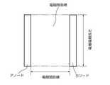
- FIG. 1 is a schematic diagram showing the area between electrodes used to calculate the circulation rate of the electrolytic solution.
- FIG. 2 is a captured image of software used when determining the size of zinc crystal grains.
- the metal layer-coated zinc foil of the present invention has a zinc-based foil body and a metal layer arranged on the surface (one side or both sides) of the foil body.
- 1. Foil body made of zinc as a base material
- a preferred embodiment of a foil body (hereinafter, also referred to as “zinc foil”) using zinc as a base material will be described.
- the above-mentioned "using zinc as a base material” means that the zinc element is preferably contained in the foil body in an amount of 80% by mass or more.
- the zinc element content can be measured by ICP emission spectroscopy.
- the size of the crystal grains of the zinc foil One of the features of the foil body used in the present invention is that the size of the zinc crystal grains in the zinc foil is smaller than that of the conventionally known zinc foil. As a result, gas generation during storage of the battery is suppressed as compared with the conventional zinc foil. The reason for this is not completely clear, but the present inventors think that it may be because the hydrogen overvoltage is changed due to the distribution of small-sized zinc crystal grains and the existence of a large number of grain boundaries. ing. From the viewpoint of further enhancing this advantage, the size of zinc crystal grains is preferably 0.2 ⁇ m or more and 50.0 ⁇ m or less, and more preferably 0.5 ⁇ m or more and 50.0 ⁇ m or less.
- crystal grain size is a concept different from the crystallite size obtained from the XRD pattern.
- the size of zinc crystal grains in the foil body used in the present invention is measured by the following method.
- an FE gun-type scanning electron microscope (OIM Data Collection Ver. 7.2.0, manufactured by TSL Solutions Co., Ltd.) equipped with an electron backscatter diffraction (hereinafter also referred to as “EBSD”) evaluation device (OIM Data Collection Ver. 7.2.0) SUPRA 55VP, manufactured by Karl Zeiss Co., Ltd.) and the attached EBSD analyzer are used.
- EBSD electron backscatter diffraction
- a sample whose cross section is cut out is prepared using an ultramicrotome, and for this sample, data on grain size in a cross-sectional view in which the thickness of the entire sample can be measured is obtained according to the EBSD method.
- background processing of EBSD measurement data "Background Subtraction”, “Normalize Integrity Histogram”, “Dynamic Background” in “Image Processing” of the EBSD evaluation device, "Dynamic Baccground”, “Dynamic Baccground” It is carried out under the condition of 160x120).
- the conditions of "Gain” and “Exposure” may be appropriately changed so that the image in "Camera” is in a state where the Kikuchi pattern is not observed by electron diffraction and is 30 ⁇ 1 fps as shown in FIG.
- the background information is acquired by "Capture Bkd”.
- the WD value when measuring the crystal grain size was set to 15 ⁇ 1 mm, and "Background Subtraction”, “Normalize Integrity Histogram” in "Image Processing", “Dynamic Baccground Checked” in the “Dynamic Background” state, and checked in the "Dynamic Background” position.
- This crystal grain size (average) is taken as the size of zinc crystal grains in the present invention.
- 1-3 Crystal structure of zinc foil
- an orientation difference of 15 ° or more is regarded as a grain boundary.
- the orientation difference at a certain grain boundary is expressed by the rotation axis and the angle of rotation in consideration of the twin grain boundaries, and the rotation axis is the following (1).
- the rotation angles are represented by 94.8 ⁇ 1 ° and 57 ⁇ 1 °, and the rotation axis is represented by (2) below, and the rotation angles are 34.8 ⁇ 1 ° and 64.3 ⁇ 1 °. In the case, it was not regarded as a grain boundary.
- the conditions of the scanning electron microscope at the time of observation are an acceleration voltage: 20 kV, an aperture diameter: 60 ⁇ m, a High Current mode, and a sample angle: 70 °.
- the conditions of the observation magnification, the measurement area, and the step size may be appropriately changed according to the size of the crystal grains.
- Metal elements contained in zinc foil The foil body used in the present invention is based on zinc as described above, and may contain 100% by mass of zinc, but contains a small amount of other metal elements other than zinc. It is preferable to be. As a result, gas generation during storage of the battery is effectively suppressed. From this point of view, it is advantageous to use a metal element having a hydrogen overvoltage higher than that of zinc or a redox potential higher than that of zinc.
- Such metal elements include at least one selected from the group consisting of bismuth, indium, aluminum, magnesium, calcium, gallium, tin, barium, strontium, silver and manganese.
- metal elements it is preferable to use at least one selected from the group consisting of bismuth, indium, aluminum, tin, silver and gallium from the viewpoint of further suppressing gas generation, and bismuth, indium, tin and silver. It is more preferable to use at least one selected from the group consisting of, from the viewpoint of further suppressing gas generation. In particular, it is even more preferable to use bismuth.
- the content ratio of metal elements in the foil body is expressed as the total amount of metal elements, and is 10 ppm or more and 10,000 ppm on a mass basis. It is preferably 15 ppm or more and 8000 ppm or less, more preferably 20 ppm or more and 7000 ppm or less, further preferably 30 ppm or more and 6500 ppm or less, and particularly preferably 40 ppm or more and 6000 ppm or less. preferable.
- the content ratio of metal elements in the foil body can be measured by ICP emission spectroscopy.
- a method compliant with JIS H1111 can be adopted for the measurement by the ICP emission spectroscopic analysis method. Specifically, after dissolving the foil body in an acidic aqueous solution such as hydrochloric acid, the concentration of contained metals other than zinc is measured by ICP emission spectroscopic analysis, and the concentration of all metals is set to 1 to contain various metal elements. Is converted as mass.
- the content ratio of bismuth in the foil body is preferably 10 ppm or more and 10000 ppm or less, more preferably 15 ppm or more and 8000 ppm or less, and 20 ppm or more and 6000 ppm. It is more preferably 30 ppm or more and 3000 ppm or less, and further preferably 40 ppm or more and 1200 ppm or less.
- the foil body used in the present invention may contain lead or cadmium as unavoidable impurities. However, it is desirable that lead is not contained from the viewpoint of reducing the environmental load. Even if the foil body contains lead, it is desirable that the content ratio is as low as possible. Specifically, the lead content is preferably 60 ppm or less, more preferably 50 ppm or less, and even more preferably 40 ppm or less on a mass basis. The lead content in the foil body is measured by ICP emission spectroscopy. Similarly, it is desirable that cadmium is not contained, or even if it is contained, the ratio thereof is as low as possible. In particular, the cadmium content is preferably 10 ppm or less on a mass basis.
- the metal elements in the foil body are as uniform as possible. Whether or not the existence state is uniform can be confirmed by observing the mapping image of the metal element described later. As a result, gas generation during storage of the battery is further suppressed as compared with the conventional zinc foil containing a metal element. In order to realize the existence state of such a metal element, it is advantageous to reduce the size of zinc crystal grains in the foil body as described above. In particular, when the metal element and zinc are not compatible with each other, the metal element tends to segregate in the vicinity of the grain boundaries of the zinc crystal grains due to this.
- zinc foil containing a metal element has been manufactured by rolling a casting of zinc containing a metal element.
- zinc containing a metal element was produced by casting, the growth of zinc crystal grains proceeded due to the cooling conditions, and it was not easy to produce small size crystal grains.
- the metal element was deposited near the grain boundary of the large-sized zinc crystal grain, and when the metal element was magnified and observed to the extent that the existence of the grain boundary could be recognized, the metal element was in a state of non-uniformity.
- the foil body is preferably manufactured by the electrolysis method described later. Due to this, small-sized zinc crystal grains can be easily generated, and it is possible for the first time to make the existence state of metal elements as uniform as possible.
- the state of existence of the metal element in the foil body used in the present invention is the metal element using energy dispersion type X-ray spectroscopy (hereinafter also referred to as “EDS”) by a scanning electron microscope (hereinafter also referred to as “SEM”). It can be judged based on the mapping image of. Specifically, when a plurality of squares having a side of 300 nm are virtually set in the mapping image, the number is preferably 2% or more, more preferably 5 with respect to the total number of the plurality of squares.
- the presence state of the metal element is uniform to the extent that the metal element is observed in the squares of% or more, more preferably 10% by number or more.
- the number of squares shall be 48 or more.
- Apparent density of zinc foil One of the features of the foil body used in the present invention is that the apparent density is lower than that of a conventionally known zinc foil, for example, a zinc foil produced by a rolling method. This also suppresses gas generation during storage of the battery, as compared with the conventional zinc foil.
- the value of the apparent density of the foil body is preferably 3.0 g / cm 3 or more and 7.0 g / cm 3 or less, and 4.0 g / cm 3 or more and 7.0 g / cm 3 or less. Is more preferable, and 5.0 g / cm 3 or more and 7.0 g / cm 3 or less is further preferable.
- the above-mentioned apparent density is a value calculated from the volume obtained by measuring the outer shape of the foil body and the mass of the foil body.
- the method for obtaining the volume by measuring the outer shape of the foil body is as follows.
- the area of the foil body in a plan view is calculated from the vertical and horizontal dimensions of the foil body.
- the thickness of the foil body is measured with a micrometer.
- the thickness shall be the arithmetic mean value of the measurement results at 15 points.
- the mass of the sample whose volume is obtained from the area and thickness is measured, and the apparent density is calculated from the volume and mass.
- the apparent density calculated in this way is also referred to as the apparent density measured by external shape measurement.
- the apparent density of the zinc foil and the apparent density of the foil body are strictly different, the metal layer provided on the surface of the foil body is extremely thin, so that the apparent density of the zinc foil and the apparent density of the foil body are extremely thin. Can be substantially identified with.
- the thickness of the foil body is preferably 10 ⁇ m or more and 500 ⁇ m or less, more preferably 15 ⁇ m or more and 400 ⁇ m or less, still more preferably 20 ⁇ m or more and 400 ⁇ m or less, and particularly preferably. It is a thin type with a thickness of 20 ⁇ m or more and 300 ⁇ m or less. The thickness of the foil body is measured by a micrometer as described above.
- the foil body can be manufactured by the rolling method described above, but it is preferably manufactured by an electrolytic method.
- Electrolysis method In the electrolysis method, the anode and cathode are immersed in an electrolytic solution containing a zinc source, and a zinc foil is deposited on the cathode.
- the foil obtained by the electrolytic method is also referred to as "electrolytic foil".
- the electrolytic solution containing a zinc source include an aqueous solution of zinc sulfate, an aqueous solution of zinc nitrate, and an aqueous solution of zinc chloride.
- the concentration of zinc contained in the electrolytic solution is preferably 30 g / L or more and 100 g / L or less from the viewpoint that a foil body having a small crystal grain size can be easily obtained.
- the anode used for electrolysis it is preferable to use a known dimensional stabilization electrode (DSE).
- DSE for example, a titanium electrode coated with iridium oxide, a titanium electrode coated with ruthenium oxide, or the like is preferably used.
- the type of cathode is not particularly limited, and a material that does not affect the reduction of zinc is appropriately selected. For example, aluminum can be used.
- the electrolytic solution contains the above-mentioned metal element source in addition to the zinc source, if necessary.
- the concentration of the metal element source contained in the electrolytic solution is preferably such that the ratio of the mass of the metal element to the total mass of zinc and the metal element in the electrolytic solution is 10 ppm or more and 10000 ppm or less, and 15 ppm or more and 8000 ppm or less. It is more preferably 20 ppm or more and 7,000 ppm or less, further preferably 30 ppm or more and 6500 ppm or less, particularly preferably 30 ppm or more and 6000 ppm or less, and particularly preferably 400 ppm or more and 6000 ppm or less. ..
- the electrolytic solution may further contain other compounds.
- sulfuric acid can be added for the purpose of adjusting the pH of the electrolytic solution.
- a pump equipped with a closed flow path, an electrolytic cell arranged in the flow path, and a pump arranged in the flow path is used. May be driven to direct the electrolytic solution in one direction and circulate in the electrolytic cell.
- the anode and cathode used for electrolysis may be immersed in an electrolytic cell with the two facing each other. It is preferable that the anode and the cathode are arranged in the electrolytic cell so that their facing surfaces (electroplated surfaces in the case of the cathode) are parallel to the flow direction of the electrolytic solution.
- Circulation rate When performing electrolysis while circulating the electrolytic solution, it is advantageous to adjust the flow rate of the electrolytic solution, that is, the circulation rate, from the viewpoint of successfully obtaining the foil body having the desired apparent density.
- the circulation speed is calculated by dividing the flow rate (L / min) of the electrolytic solution by the area between electrodes (mm 2). As shown in FIG. 1, the area between electrodes is represented by the product of the distance between electrodes (mm) and the length of electrodeposited electrodes (mm). In FIG. 1, it is preferable to distribute the electrolytic solution in a direction orthogonal to the paper surface.
- the current density during electrolysis is one of the factors that affect the size of zinc crystal grains in the obtained foil body and the apparent density of the foil body. Specifically, by increasing the current density above the conditions of normal zinc electrolysis, a large number of fine crystals can be generated, whereby a foil body having a small crystal grain size can be easily obtained. From this viewpoint, it is preferable to set the current density to below 1000A / m 2 or more 10000 A / m 2, further preferably set to below 1000A / m 2 or more 6000A / m 2, 1000A / m 2 or more 4000A / m It is more preferable to set it to 2 or less. On the other hand, conventionally, the current density when manufacturing the electrolytic zinc foil is as low as about 500 A / m 2.
- the electrolytic solution can be subjected to electrolysis in a non-heated state or a heated state.
- the temperature of the electrolytic solution is preferably set to 10 ° C. or higher and 90 ° C. or lower.
- the temperature of the electrolytic solution is more preferably 20 ° C. or higher and 90 ° C. or lower, further preferably 30 ° C. or higher and 80 ° C. or lower, and further preferably 30 ° C. or higher and 70 ° C. or lower. This is done until the thickness of the foil body reaches the desired value.
- Electrolysis is performed under the above conditions, and zinc is reduced and precipitated on the cathode immersed in the electrolytic solution to obtain the desired foil body.
- a coating metal layer (hereinafter, also simply referred to as “metal layer”) arranged on the surface of the foil body described above will be described.
- This metal layer is arranged on one side or both sides of the surface of the foil body by a coating forming means described later.
- Metal elements contained in the coated metal layer examples include at least one selected from the group consisting of bismuth, indium, aluminum, gallium, tin, silver and manganese. Among these metal elements, it is preferable to use at least one of bismuth and indium from the viewpoint of further suppressing gas generation.
- the thickness of the metal layer is preferably 5.0 ⁇ 10 -1 nm or more and 3.0 ⁇ 10 3 nm or less. It is more preferably 1.0 nm or more and 1.0 ⁇ 10 3 nm or less, and further preferably 1.0 ⁇ 10 1 nm or more and 5.0 ⁇ 10 2 nm or less. By forming the coated metal layer in this range, gas generation can be effectively suppressed.
- the thickness of the metal layer is measured by a light emitting surface analyzer described later.
- the metal layer is arranged on one side or both sides of the surface of the foil body.
- the thickness (T S of the other surface than the thickness of one surface (T C) ) Is larger.
- the ratio of the thickness (T S / T C) is 2 or more, more preferably 2.3 or more.
- the upper limit of T S / T C is preferably 5.0.
- the foil body is composed of, for example, an electrolytic foil
- one surface is an electrode surface of the foil body (hereinafter, also referred to as “C surface”)
- the other surface is a precipitation surface in contact with the electrolytic solution (hereinafter, “S”). Also called “face”).
- the thickness of the metal layer in this case, towards the thickness of the S-plane than the thickness of the C-plane (T C) (T S) that is greater, from the viewpoint of the effect of the becomes more pronounced.
- Which of the surfaces of the foil body is the C surface and which is the S surface can be determined by surface observation.
- the C-plane is smoother than the S-plane and has a small specific surface area. Further, the size of the crystal grains is smaller on the C plane than on the S plane.
- the thickness of the metal layer coated zinc foil having the coated metal layer and the foil body is preferably 1 ⁇ m or more and 1000 ⁇ m or less, more preferably 3 ⁇ m or more and 800 ⁇ m or less, and further preferably 10 ⁇ m or more and 500 ⁇ m or less. It is thin.
- the thickness of the metal layer-coated zinc foil is measured by the same method as the thickness of the foil body.
- Such a thin metal layer-coated zinc foil is particularly suitable as a negative electrode material for a thin primary battery or a secondary battery.
- a method for manufacturing a coated metal layer that is, a method for forming a metal layer coating on a foil body will be described.
- the coating forming means a sputtering method, a PVD method, a CVD method, a reduction plating method, an electroplating method, a substitution plating method, or the like can be used.
- the substitution plating method it is preferable to use the substitution plating method from the viewpoint of the continuity of the process when the foil body is manufactured by the electrolytic method.
- substitution plating method is a plating method that utilizes the difference in ionization tendency, and is an excellent method for forming a metal layer.
- a preferred embodiment of the substitution plating method will be described below.
- a substitution plating solution for the substitution plating method a nitric acid aqueous solution of a metal element having an arbitrary concentration or another acidic aqueous solution is prepared and dissolved in ion-exchanged water.
- the metal element includes at least one selected from the group consisting of bismuth, indium, aluminum, gallium, tin, silver and manganese. Among these metal elements, it is preferable to use at least one of bismuth and indium from the viewpoint of further suppressing gas generation.
- the concentration of the metal element in the replacement plating solution can be appropriately selected depending on the type of the target metal element, the thickness of the coating metal layer, and other conditions.
- concentration of bismuth in the replacement plating solution is preferably adjusted to 0.1 mg / L or more and 10,0000.0 mg / L or less.
- bismuth nitrate can be used as the bismuth compound.
- concentration of indium in the replacement plating solution is preferably adjusted to 0.1 mg / L or more and 10,0000.0 mg / L or less.
- Various complexing agents such as a chelating agent such as ethylenediaminetetraacetic acid may be added to the replacement plating solution, if necessary.
- the pH of the replacement plating solution may be adjusted to a predetermined range by adding an alkaline solution such as aqueous ammonia or sodium hydroxide solution to the replacement plating solution.
- an alkaline solution such as aqueous ammonia or sodium hydroxide solution
- the immersion temperature and the immersion time may be appropriately adjusted according to the thickness of the metal layer.
- the electroplating method is a plating method using an electric current, and is an excellent method for forming a metal layer.
- a preferred embodiment of the electroplating method will be described below.
- the electroplating solution for the electroplating method a nitric acid aqueous solution of a metal element having an arbitrary concentration or another acidic aqueous solution is prepared.
- the metal element includes at least one selected from the group consisting of bismuth, indium, aluminum, gallium, tin, silver and manganese.
- the concentration of the metal element in the electroplating solution can be appropriately selected depending on the type of the target metal element, the thickness of the coating metal layer, and other conditions.
- the tin concentration in the electroplating solution is preferably adjusted to 1.0 g / L or more and 100.0 g / L or less.
- tin nitrate can be used as the tin compound.
- the concentration of indium in the electroplating solution is preferably adjusted to 1.0 g / L or more and 100.0 g / L or less.
- various complexing agents such as a chelating agent such as ethylenediaminetetraacetic acid may be added to the electroplating solution.
- the pH of the electroplating solution may be adjusted to a predetermined range by adding an alkaline solution such as aqueous ammonia or sodium hydroxide solution to the electroplating solution.
- an alkaline solution such as aqueous ammonia or sodium hydroxide solution
- a foil body coated with a metal layer can be obtained.
- the current density, immersion temperature and time at the time of energization may be appropriately adjusted according to the surface condition and thickness of the target metal layer.
- the foil body immersed in the electroplating solution is used as the cathode, and the counter electrode is used as the anode.
- the counter electrode it is preferable to use a flat plate made of the same type of metal as the metal layer covering the foil body. As a result, the concentration of the metal element in the electroplating can be kept constant during energization.
- Negative electrode active material for batteries The metal layer-coated zinc foil obtained as described above is suitably used as a negative electrode active material for batteries in primary batteries and secondary batteries.
- the primary battery include a manganese zinc battery and a zinc air battery.
- the secondary battery include a nickel-zinc battery and a zinc-air battery.
- the zinc foil coated with a metal layer of the present invention is particularly preferably used as a negative electrode active material for a thin battery. Further, since the metal layer-coated zinc foil itself has conductivity, the zinc foil also functions as a current collector. This makes it possible to use the metal layer-coated zinc foil itself as the negative electrode without using a current collector.
- the thin battery has a thickness of, for example, several millimeters or less at the maximum.
- Many thin batteries have an outer case made of a softer material than a conventional battery (for example, a cylindrical nickel-plated iron outer case), for example, a resin such as a metal laminated resin film or a heat-resistant resin film.
- a battery having a power generation element having a positive electrode, an electrolyte, and a negative electrode as one unit and a resin exterior body accommodating the power generation element can be mentioned.
- expansion of the battery due to gas generation is likely to occur, and the use of the metal layer-coated zinc foil of the present invention can effectively suppress gas generation.
- the thickness of the structure containing one unit of the positive electrode, the electrolyte and the negative electrode is generally as thin as 5 mm or less. In a thin battery, it is preferable to use the unit as a single unit.
- Example 1 Preparation of electrolytic solution
- Zinc oxide was used as the zinc compound. This was dissolved in water together with sulfuric acid to prepare an electrolytic solution. The concentration of zinc in the electrolytic solution was 50 g / L. The concentration of sulfuric acid was set to 200 g / L as a value obtained by converting the total amount of sulfate ions into H 2 SO 4. Bismuth nitrate was added here. The concentration of bismuth was adjusted so that the content ratio of bismuth contained in the target zinc foil was 750 ppm.
- (2) Reduction and precipitation of zinc As an anode, a DSE made of a titanium electrode coated with iridium oxide was used. An aluminum plate was used as the cathode.
- Example 2 A replacement plating solution was prepared in the same manner as in Example 1 except that the bismuth concentration of the surface treatment solution was 50 mg / L and ethylenediaminetetraacetic acid was added in an equimolar amount with bismuth nitrate. Further, a zinc foil coated with a metal bismuth layer was obtained in the same manner as in Example 1 except that the immersion time of the foil body was set to 10 minutes.
- Example 3 The replacement plating solution was used in the same manner as in Example 1 except that the indium concentration was adjusted to 960 mg / L by changing to indium nitrate instead of bismuth nitrate, and sodium hydroxide was added to adjust the pH to 6.5. Prepared. Further, a metal indium layer-coated zinc foil was obtained in the same manner as in Example 1 except that the immersion time of the foil body was 30 seconds.
- Example 4 As the electroplating solution, an electroplating solution DAIN IN-161 (manufactured by Daiwa Kasei Co., Ltd.) adjusted to have an indium concentration of 30,000 mg / L was used. An indium plate (manufactured by Niraco) was used as the anode. The foil body obtained in (2) above was used as the cathode. A cathode was placed between the two anodes. Under the condition that the electroplating liquid is kept at 30 ° C., energization is applied between the anode and the cathode so that a metal layer having a predetermined thickness is formed on the surface of the foil body, and the zinc foil coated with the metal indium layer is formed. Obtained. The current density was 1 A / cm 2 .
- Example 5 As the electroplating solution, DAIN TINGOOD 101 (manufactured by Daiwa Kasei Co., Ltd.), which was adjusted so that the tin concentration was 20000 mg / L, was used. A tin plate (manufactured by Niraco) was used as the anode. The current density was set to 2 A / cm 2 and energization was performed while the electroplating solution was kept at 25 ° C. A zinc foil coated with a metallic tin layer was obtained in the same manner as in Example 4 except for these.
- the metal element seven kinds of elements such as bismuth, indium, aluminum, gallium, tin, silver and manganese were measured. From the depth profile of each of the obtained elements, an element having a strength of 0.2 Volt or more and having a peak top was determined to be a metal element contained in the coated metal layer. The thickness of the metal layer was calculated using the above-mentioned sputter rate based on the depth profile of the discriminated metal element, starting from the outermost surface, and based on the time when the strength decreased to 1/5 with respect to the maximum strength.
- the peak top position is not always located only on the outermost surface of the metal layer-coated zinc foil, and may be located between the outermost surface and the zinc layer.
- the thickness of the metal layer starts from the outermost surface and is closest to the zinc layer among the multiple times when the intensity of the metal element becomes 1/5 of the peak top.
- the time can be selected as the end point and the thickness of the metal layer can be calculated using the sputter rate based on the time.
- a zinc foil for a negative electrode active material in which the amount of gas generated is suppressed more than before in the battery, particularly when used as the negative electrode active material of a thin battery.
Landscapes
- Chemical & Material Sciences (AREA)
- Chemical Kinetics & Catalysis (AREA)
- Electrochemistry (AREA)
- General Chemical & Material Sciences (AREA)
- Engineering & Computer Science (AREA)
- Materials Engineering (AREA)
- Metallurgy (AREA)
- Organic Chemistry (AREA)
- Mechanical Engineering (AREA)
- Cell Electrode Carriers And Collectors (AREA)
- Battery Electrode And Active Subsutance (AREA)
Abstract
本発明の金属層被覆亜鉛箔は、亜鉛を母材とする箔本体と、該箔本体の表面に配置された金属層とを有する。被覆金属層に含まれる金属元素が、ビスマス、インジウム、アルミニウム、ガリウム、スズ、銀及びマンガンからなる群より選択される少なくとも一種である。被覆金属層の厚みが5.0×10⁻¹nm以上3.0×10³nm以下であることが好ましい。被覆金属層が、箔本体の表面の片面又は両面に配置されることが好ましい。箔本体が、電解箔であることが好ましい。
Description
本発明は、金属層被覆亜鉛箔及びその製造方法に関し、特に、一次電池又は二次電池用の負極活物質材料として好適に用いることができる金属層被覆亜鉛箔及びその製造方法に関する。
本出願人は、先に、亜鉛を母材とし、ビスマスを含む亜鉛箔及びその亜鉛箔を用いた一次電池用負極活物質材料を提案した(特許文献1参照)。この亜鉛箔においては、ビスマスの含有割合が質量基準で100ppm以上10000ppm以下であり、亜鉛の結晶粒のサイズが0.2μm以上8μm以下である。この亜鉛箔を負極活物質材料として用いると、電池の長期保存中のガス発生量がこれまでよりも抑制されるという利点がある。
特許文献1に記載の亜鉛箔によれば、電池の長期保存中のガス発生量を実用的なレベルにまで低減させることが可能である。しかし、例えば厚さが数ミリメートル程度である薄型電池の場合、少量のガス発生であっても電池の厚みの増大が顕著になる。薄型電池は携帯電子機器の電源として用いられる場面が多いことから、電池の厚みの増大は携帯電子機器の信頼性に影響する。したがって、薄型電池はガス発生に対する要求特性が従来の電池よりも格段に厳しくなっている。
したがって本発明の課題は、特に薄型電池の負極活物質材料として用いた場合に、その電池において、ガス発生量がこれまでよりも抑制された負極活物質材料用の亜鉛箔を提供することにある。
したがって本発明の課題は、特に薄型電池の負極活物質材料として用いた場合に、その電池において、ガス発生量がこれまでよりも抑制された負極活物質材料用の亜鉛箔を提供することにある。
本発明は、亜鉛を母材とする箔本体と、該箔本体の表面に配置された金属層とを有する、金属層被覆亜鉛箔であって、前記金属層に含まれる金属元素が、ビスマス、インジウム、アルミニウム、ガリウム、スズ、銀及びマンガンからなる群より選択される少なくとも一種である、金属層被覆亜鉛箔を提供することによって前記の課題を解決したものである。
以下本発明を、その好ましい実施形態に基づき説明する。本発明の金属層被覆亜鉛箔は、亜鉛を母材とする箔本体と、その箔本体の表面(片面又は両面)に配置された金属層とを有するものである。
1.亜鉛を母材とする箔本体
まず、亜鉛を母材とする箔本体(以下、「亜鉛箔」ともいう。)の好ましい実施形態について説明する。
前記の「亜鉛を母材とする」とは、箔本体のうち、亜鉛元素が好ましくは80質量%以上の含有率であることをいう。亜鉛元素の含有率は、ICP発光分光分析法により測定することができる。
1.亜鉛を母材とする箔本体
まず、亜鉛を母材とする箔本体(以下、「亜鉛箔」ともいう。)の好ましい実施形態について説明する。
前記の「亜鉛を母材とする」とは、箔本体のうち、亜鉛元素が好ましくは80質量%以上の含有率であることをいう。亜鉛元素の含有率は、ICP発光分光分析法により測定することができる。
1-1.亜鉛箔の結晶粒のサイズ
本発明で用いられる箔本体は、従来知られている亜鉛箔に比べて、亜鉛箔中での亜鉛の結晶粒のサイズが小さいことを特徴の一つとしている。このことによって、従来の亜鉛箔に比べて、電池の保存中のガス発生が抑制される。この理由は完全に明らかではないが、小さいサイズの亜鉛の結晶粒が分布し、粒界が多数存在する状態となることで、水素過電圧が変化しているためではないかと本発明者らは考えている。この利点を一層顕著なものとする観点から、亜鉛の結晶粒のサイズは0.2μm以上50.0μm以下とすることが好ましく、0.5μm以上50.0μm以下とすることが更に好ましく、1.0μm以上30.0μm以下とすることが一層好ましく、2.0μm以上26.0μm以下とすることが更に一層好ましく、3.0μm以上26.0μm以下とすることが特に好ましい。箔本体にこのようなサイズの結晶粒を生じさせるための好適な方法については後述する。なお、結晶粒のサイズは、XRDパターンから求められる結晶子サイズとは異なる概念であることに留意すべきである。
本発明で用いられる箔本体は、従来知られている亜鉛箔に比べて、亜鉛箔中での亜鉛の結晶粒のサイズが小さいことを特徴の一つとしている。このことによって、従来の亜鉛箔に比べて、電池の保存中のガス発生が抑制される。この理由は完全に明らかではないが、小さいサイズの亜鉛の結晶粒が分布し、粒界が多数存在する状態となることで、水素過電圧が変化しているためではないかと本発明者らは考えている。この利点を一層顕著なものとする観点から、亜鉛の結晶粒のサイズは0.2μm以上50.0μm以下とすることが好ましく、0.5μm以上50.0μm以下とすることが更に好ましく、1.0μm以上30.0μm以下とすることが一層好ましく、2.0μm以上26.0μm以下とすることが更に一層好ましく、3.0μm以上26.0μm以下とすることが特に好ましい。箔本体にこのようなサイズの結晶粒を生じさせるための好適な方法については後述する。なお、結晶粒のサイズは、XRDパターンから求められる結晶子サイズとは異なる概念であることに留意すべきである。
1-2.亜鉛箔の結晶粒サイズの測定方法
本発明で用いられる箔本体における亜鉛の結晶粒のサイズは次の方法で測定される。測定には、電子線後方散乱回折(以下「EBSD」ともいう。)評価装置(OIM Data Collection Ver.7.2.0、株式会社TSLソリューションズ製)を搭載したFE銃型の走査型電子顕微鏡(SUPRA 55VP、カールツァイス株式会社製)及び付属のEBSD解析装置を用いる。ウルトラミクロトームを用いて断面が切り出されたサンプルを調製し、このサンプルについて、EBSD法に準じて、サンプル全体の厚みを測定し得る断面視における結晶粒サイズのデータを得る。
EBSDの測定データのバックグラウンド処理は、前記EBSD評価装置の「Image Proccessing」内の「Background Subtraction」、「Normalize Intensity Histgram」、「Dynamic Background Subtraction」のチェックを外した状態の「Binning」が4x4(160x120)の条件にて実施する。「Gain」、「Exposure」は「Camera」内の像が図2に示すとおり電子回折において菊池パターンが観察されない状態且つ30±1fpsになるように適宜条件を変更してもよい。この条件下で「Image Proccessing Function」内の「Ave」の値が10の条件下で、「Capture Bkd」にてバックグラウンドの情報を取得する。
結晶粒サイズを測定するときのWD値は15±1mmとし、「Image Proccessing」内の「Background Subtraction」、「Normalize Intensity Histgram」、「Dynamic Background Subtraction」のチェックを入れた状態で、観察箇所上で前記EBSD評価装置の「Capture Pattern」内の「Phase」から「Zn」を選択し、「Solutions」の「Fit」の値が1.5以内、「CI」の値が0.1より高い条件下にて、WD値を調整する。
結晶粒サイズは「Scan」内の「Capture SEM」にて取り出したサンプル断面の写真を「Start Scan」にて測定する。
この測定データを、EBSD解析プログラム(OIM Analysis Ver.7.3.1、株式会社TSLソリューションズ製)の分析メニューの「Grain Size Quick Chart」より「All data」を使用して、結晶粒サイズ(平均)(Grain Size(Averege))を求める。この結晶粒サイズ(平均)を、本発明における亜鉛の結晶粒のサイズとする。
1-3.亜鉛箔の結晶構造
本測定においては、方位差15°以上を結晶粒界とみなす。ただし、亜鉛の結晶構造は六方最密充填構造であるために双晶粒界を考慮して、ある粒界での方位差を回転軸と回転角で表し、回転軸が下記の(1)で表され、回転角が94.8±1°及び57±1°の場合と、回転軸が下記の(2)で表され、回転角が34.8±1°及び64.3±1°の場合は、結晶粒界とみなさなかった。観察時の走査型電子顕微鏡の条件は加速電圧:20kV、アパーチャー径:60μm、High Current mode、試料角度:70°とする。観察倍率、測定領域及びステップサイズは、結晶粒の大きさに応じて、適宜、条件を変更してもよい。
本発明で用いられる箔本体における亜鉛の結晶粒のサイズは次の方法で測定される。測定には、電子線後方散乱回折(以下「EBSD」ともいう。)評価装置(OIM Data Collection Ver.7.2.0、株式会社TSLソリューションズ製)を搭載したFE銃型の走査型電子顕微鏡(SUPRA 55VP、カールツァイス株式会社製)及び付属のEBSD解析装置を用いる。ウルトラミクロトームを用いて断面が切り出されたサンプルを調製し、このサンプルについて、EBSD法に準じて、サンプル全体の厚みを測定し得る断面視における結晶粒サイズのデータを得る。
EBSDの測定データのバックグラウンド処理は、前記EBSD評価装置の「Image Proccessing」内の「Background Subtraction」、「Normalize Intensity Histgram」、「Dynamic Background Subtraction」のチェックを外した状態の「Binning」が4x4(160x120)の条件にて実施する。「Gain」、「Exposure」は「Camera」内の像が図2に示すとおり電子回折において菊池パターンが観察されない状態且つ30±1fpsになるように適宜条件を変更してもよい。この条件下で「Image Proccessing Function」内の「Ave」の値が10の条件下で、「Capture Bkd」にてバックグラウンドの情報を取得する。
結晶粒サイズを測定するときのWD値は15±1mmとし、「Image Proccessing」内の「Background Subtraction」、「Normalize Intensity Histgram」、「Dynamic Background Subtraction」のチェックを入れた状態で、観察箇所上で前記EBSD評価装置の「Capture Pattern」内の「Phase」から「Zn」を選択し、「Solutions」の「Fit」の値が1.5以内、「CI」の値が0.1より高い条件下にて、WD値を調整する。
結晶粒サイズは「Scan」内の「Capture SEM」にて取り出したサンプル断面の写真を「Start Scan」にて測定する。
この測定データを、EBSD解析プログラム(OIM Analysis Ver.7.3.1、株式会社TSLソリューションズ製)の分析メニューの「Grain Size Quick Chart」より「All data」を使用して、結晶粒サイズ(平均)(Grain Size(Averege))を求める。この結晶粒サイズ(平均)を、本発明における亜鉛の結晶粒のサイズとする。
1-3.亜鉛箔の結晶構造
本測定においては、方位差15°以上を結晶粒界とみなす。ただし、亜鉛の結晶構造は六方最密充填構造であるために双晶粒界を考慮して、ある粒界での方位差を回転軸と回転角で表し、回転軸が下記の(1)で表され、回転角が94.8±1°及び57±1°の場合と、回転軸が下記の(2)で表され、回転角が34.8±1°及び64.3±1°の場合は、結晶粒界とみなさなかった。観察時の走査型電子顕微鏡の条件は加速電圧:20kV、アパーチャー径:60μm、High Current mode、試料角度:70°とする。観察倍率、測定領域及びステップサイズは、結晶粒の大きさに応じて、適宜、条件を変更してもよい。

1-4.亜鉛箔の含有金属元素
本発明に用いられる箔本体は、上述のとおり亜鉛を母材とするものであり、亜鉛が100質量%のものでもよいが、亜鉛以外の少量の別の金属元素を含んでいることが好ましい。それによって電池の保存中のガス発生が効果的に抑制される。この観点から、金属元素として、水素過電圧が亜鉛よりも高いか又は酸化還元電位が亜鉛よりも貴であるものを用いることが有利である。そのような金属元素としては、ビスマス、インジウム、アルミニウム、マグネシウム、カルシウム、ガリウム、スズ、バリウム、ストロンチウム、銀及びマンガンからなる群より選択される少なくとも一種が挙げられる。これらの金属元素のうち、ビスマス、インジウム、アルミニウム、スズ、銀及びガリウムからなる群より選択される少なくとも一種を用いることが、ガス発生が更に抑制される点から好ましく、ビスマス、インジウム、スズ及び銀からなる群より選択される少なくとも一種を用いることが、ガス発生の一層の抑制の点から更に好ましい。特に、ビスマスを用いることがより更に一層好ましい。
本発明に用いられる箔本体は、上述のとおり亜鉛を母材とするものであり、亜鉛が100質量%のものでもよいが、亜鉛以外の少量の別の金属元素を含んでいることが好ましい。それによって電池の保存中のガス発生が効果的に抑制される。この観点から、金属元素として、水素過電圧が亜鉛よりも高いか又は酸化還元電位が亜鉛よりも貴であるものを用いることが有利である。そのような金属元素としては、ビスマス、インジウム、アルミニウム、マグネシウム、カルシウム、ガリウム、スズ、バリウム、ストロンチウム、銀及びマンガンからなる群より選択される少なくとも一種が挙げられる。これらの金属元素のうち、ビスマス、インジウム、アルミニウム、スズ、銀及びガリウムからなる群より選択される少なくとも一種を用いることが、ガス発生が更に抑制される点から好ましく、ビスマス、インジウム、スズ及び銀からなる群より選択される少なくとも一種を用いることが、ガス発生の一層の抑制の点から更に好ましい。特に、ビスマスを用いることがより更に一層好ましい。
1-5.亜鉛箔の含有金属元素の含有割合
電池の保存中のガス発生を効果的に抑制する観点から、箔本体における金属元素の含有割合は、金属元素の合計量で表して、質量基準で10ppm以上10000ppm以下であることが好ましく、15ppm以上8000ppm以下であることが更に好ましく、20ppm以上7000ppm以下であることが一層好ましく、30ppm以上6500ppm以下であることが更に一層好ましく、特に40ppm以上6000ppm以下であることが好ましい。箔本体における金属元素の含有割合は、ICP発光分光分析法にて測定できる。ICP発光分光分析法による測定には、JIS H1111に準拠した方法を採用できる。具体的には、塩酸等の酸性水溶液に箔本体を溶解させた後、ICP発光分光分析法で亜鉛以外の含有金属の濃度を測定し、全金属の溶液濃度を1として各種金属元素の含有割合を質量として換算する。
電池の保存中のガス発生を効果的に抑制する観点から、箔本体における金属元素の含有割合は、金属元素の合計量で表して、質量基準で10ppm以上10000ppm以下であることが好ましく、15ppm以上8000ppm以下であることが更に好ましく、20ppm以上7000ppm以下であることが一層好ましく、30ppm以上6500ppm以下であることが更に一層好ましく、特に40ppm以上6000ppm以下であることが好ましい。箔本体における金属元素の含有割合は、ICP発光分光分析法にて測定できる。ICP発光分光分析法による測定には、JIS H1111に準拠した方法を採用できる。具体的には、塩酸等の酸性水溶液に箔本体を溶解させた後、ICP発光分光分析法で亜鉛以外の含有金属の濃度を測定し、全金属の溶液濃度を1として各種金属元素の含有割合を質量として換算する。
1-6.亜鉛箔含有金属元素のビスマス
前記の金属元素のうち、特にビスマスが箔本体中に含まれていると、電池の保存中のガス発生が一層効果的に抑制されるので好ましい。電池の保存中のガス発生を更に一層抑制するために、箔本体におけるビスマスの含有割合は質量基準で10ppm以上10000ppm以下であることが好ましく、15ppm以上8000ppm以下であることが更に好ましく、20ppm以上6000ppm以下であることが一層好ましく、30ppm以上3000ppm以下であることが更に一層好ましく、特に40ppm以上1200ppm以下であることがより更に好ましい。
前記の金属元素のうち、特にビスマスが箔本体中に含まれていると、電池の保存中のガス発生が一層効果的に抑制されるので好ましい。電池の保存中のガス発生を更に一層抑制するために、箔本体におけるビスマスの含有割合は質量基準で10ppm以上10000ppm以下であることが好ましく、15ppm以上8000ppm以下であることが更に好ましく、20ppm以上6000ppm以下であることが一層好ましく、30ppm以上3000ppm以下であることが更に一層好ましく、特に40ppm以上1200ppm以下であることがより更に好ましい。
1-7.亜鉛箔含有金属元素の鉛とカドミウム
本発明に用いられる箔本体には、不可避的不純物として、鉛又はカドミウムが含まれることがある。しかしながら、環境負荷を軽減する観点から鉛は非含有であることが望ましい。箔本体が鉛を含有したとしても、その含有割合は極力低いことが望ましい。具体的には、鉛の含有割合が質量基準で60ppm以下であることが好ましく、50ppm以下であることが更に好ましく、40ppm以下であることが一層好ましい。箔本体における鉛の含有割合は、ICP発光分光分析法によって測定される。また、カドミウムも同様に、非含有であるか、又は含有したとしてもその割合は極力低いことが望ましい。特にカドミウムの含有割合は質量基準で10ppm以下であることが望ましい。
本発明に用いられる箔本体には、不可避的不純物として、鉛又はカドミウムが含まれることがある。しかしながら、環境負荷を軽減する観点から鉛は非含有であることが望ましい。箔本体が鉛を含有したとしても、その含有割合は極力低いことが望ましい。具体的には、鉛の含有割合が質量基準で60ppm以下であることが好ましく、50ppm以下であることが更に好ましく、40ppm以下であることが一層好ましい。箔本体における鉛の含有割合は、ICP発光分光分析法によって測定される。また、カドミウムも同様に、非含有であるか、又は含有したとしてもその割合は極力低いことが望ましい。特にカドミウムの含有割合は質量基準で10ppm以下であることが望ましい。
1-8.亜鉛箔含有金属元素の存在状態
箔本体において前記の金属元素の存在状態は明らかでないが、少なくとも亜鉛との固溶体の状態ではない。固溶体の状態とは金属元素の添加によって亜鉛の結晶構造が変化する状態のことである。金属元素を含有する箔本体の断面を、走査型電子顕微鏡によるエネルギー分散型X線分光法(特性X線検出法)を用いて元素マッピングすると、亜鉛の存在状態としてのマッピング像と金属元素の存在状態としてのマッピング像とがそれぞれ得られる。
箔本体において前記の金属元素の存在状態は明らかでないが、少なくとも亜鉛との固溶体の状態ではない。固溶体の状態とは金属元素の添加によって亜鉛の結晶構造が変化する状態のことである。金属元素を含有する箔本体の断面を、走査型電子顕微鏡によるエネルギー分散型X線分光法(特性X線検出法)を用いて元素マッピングすると、亜鉛の存在状態としてのマッピング像と金属元素の存在状態としてのマッピング像とがそれぞれ得られる。
箔本体中の金属元素はその存在状態が極力均一であることが好ましい。なお、存在状態が均一か否かは、後述する金属元素のマッピング像の観察によって確認することができる。これによって、従来の金属元素含有の亜鉛箔に比べて、電池の保存中のガス発生が一層抑制される。このような金属元素の存在状態を実現するためには、箔本体における亜鉛の結晶粒のサイズを上述のとおり小さくすることが有利である。特に、金属元素と亜鉛とが相溶性がない場合には、そのことに起因して、金属元素は亜鉛の結晶粒の粒界付近に偏析しやすい。この場合、亜鉛の結晶粒のサイズが大きいと、粒界の存在が分かる程度にマクロで観察した場合、金属元素の存在が不均一となる。逆に、亜鉛の結晶粒のサイズが小さいと、粒界の存在が分かる程度にマクロで観察した場合、金属元素の存在状態が均一となる。この理由によって、箔本体における亜鉛の結晶粒のサイズを小さくすることが有利である。
従来、金属元素含有の亜鉛箔は、金属元素含有の亜鉛の鋳造物を圧延することによって製造していた。鋳造によって金属元素含有の亜鉛を製造すると、冷却条件に起因して、亜鉛の結晶粒の成長が進行し、小さいサイズの結晶粒を生成させることが容易でなかった。その結果、大きなサイズの亜鉛の結晶粒の粒界付近に金属元素が析出し、粒界の存在が分かる程度に拡大して観察した場合、金属元素が不均一に存在する状態となっていた。このこととは対照的に、本発明においては、好適には後述する電解法によって箔本体を製造している。このことに起因して、小さいサイズの亜鉛の結晶粒を容易に生成させることができ、金属元素の存在状態を極力均一なものとすることが初めて可能となった。
本発明に用いられる箔本体における金属元素の存在状態は、走査型電子顕微鏡(以下「SEM」ともいう。)によるエネルギー分散型X線分光法(以下「EDS」ともいう。)を用いた金属元素のマッピング像に基づき判断できる。詳細には、マッピング像中に、一辺が300nmの正方形の複数のマス目を仮想的に設定したときに、該複数のマス目の総数に対して好ましくは2個数%以上、更に好ましくは5個数%以上、一層好ましくは10個数%以上のマス目内に金属元素が観察される程度に、金属元素の存在状態が均一になっている。マス目の数は48個以上とする。
1-9.亜鉛箔の見かけ密度
本発明に用いられる箔本体は、従来知られている亜鉛箔、例えば圧延法で製造された亜鉛箔に比べて見かけ密度が低いことも特徴の一つである。これによっても、従来の亜鉛箔に比べて、電池の保存中のガス発生が抑制される。
本発明に用いられる箔本体は、従来知られている亜鉛箔、例えば圧延法で製造された亜鉛箔に比べて見かけ密度が低いことも特徴の一つである。これによっても、従来の亜鉛箔に比べて、電池の保存中のガス発生が抑制される。
箔本体の見かけ密度の値は、具体的には3.0g/cm3以上7.0g/cm3以下であることが好ましく、4.0g/cm3以上7.0g/cm3以下であることが更に好ましく、5.0g/cm3以上7.0g/cm3以下であることが一層好ましい。箔本体の見かけ密度をこの範囲に設定することで、電池の保存中のガス発生が効果的に抑制される。このような見かけ密度を有する箔本体の好適な製造方法については後述する。
前記の見かけ密度とは、箔本体の外形測定によって求められる体積と、箔本体の質量とから算出される値である。箔本体の外形測定によって体積を求める方法は以下のとおりである。箔本体の平面視での面積を、箔本体の縦及び横の寸法から算出する。箔本体の厚みを、マイクロメーターによって測定する。厚みは、15箇所での測定結果の相加平均値とする。面積と厚みとから体積を求めた試料の質量を測定し、体積と質量とから見かけ密度を算出する。こうして算出された見掛け密度を外形測定による見掛け密度ともいう。なお、亜鉛箔の見掛け密度と箔本体の見掛け密度とは厳密には異なるが、箔本体の表面に設けられた金属層はその厚みが極めて薄いので、亜鉛箔の見掛け密度と箔本体の見掛け密度とは実質的に同一視できる。
1-10.亜鉛箔の見かけ密度以外のその他の密度
見かけ密度以外のその他の密度も、ガス発生に影響するものと考えられる。その他の密度の測定方法として、例えばアルキメデス法やJIS Z8807:2012に準じた他の測定方法もある。更に他の測定方法として、比重瓶による密度及び比重の測定方法、ルシャテリエ比重瓶による密度及び比重の測定方法、液中ひょう量法による密度及び比重の測定方法、音響法による密度及び比重の測定方法、気体置換法による密度及び比重の測定方法が挙げられる。
見かけ密度以外のその他の密度も、ガス発生に影響するものと考えられる。その他の密度の測定方法として、例えばアルキメデス法やJIS Z8807:2012に準じた他の測定方法もある。更に他の測定方法として、比重瓶による密度及び比重の測定方法、ルシャテリエ比重瓶による密度及び比重の測定方法、液中ひょう量法による密度及び比重の測定方法、音響法による密度及び比重の測定方法、気体置換法による密度及び比重の測定方法が挙げられる。
1-11.亜鉛箔の厚み
上述した箔本体の見かけ密度に関連し、当該箔本体は、その厚みが好ましくは10μm以上500μm以下、更に好ましくは15μm以上400μm以下、更に一層好ましくは20μm以上400μm以下、特に好ましくは20μm以上300μm以下という薄型のものである。箔本体の厚みは上述したとおりマイクロメーターによって測定される。
上述した箔本体の見かけ密度に関連し、当該箔本体は、その厚みが好ましくは10μm以上500μm以下、更に好ましくは15μm以上400μm以下、更に一層好ましくは20μm以上400μm以下、特に好ましくは20μm以上300μm以下という薄型のものである。箔本体の厚みは上述したとおりマイクロメーターによって測定される。
2.箔本体の製造方法
続いて、箔本体の好適な製造方法について説明する。箔本体は、前述した圧延法により製造することもできるが、電解法によって製造することが好ましい。
続いて、箔本体の好適な製造方法について説明する。箔本体は、前述した圧延法により製造することもできるが、電解法によって製造することが好ましい。
2-1.電解法
電解法においては、亜鉛源を含む電解液にアノード及びカソードを浸漬させ、カソードに亜鉛箔を析出させる。電解法により得られた箔を「電解箔」ともいう。亜鉛源を含む電解液としては、硫酸亜鉛水溶液、硝酸亜鉛水溶液、塩化亜鉛水溶液等が挙げられる。電解液に含まれる亜鉛の濃度は、30g/L以上100g/L以下であることが、結晶粒のサイズが小さい箔本体を容易に得ることができる点から好ましい。電解に使用するアノードとしては、公知の寸法安定化電極(DSE)を用いることが好ましい。DSEとしては、例えば酸化イリジウムをコートしたチタン電極、酸化ルテニウムをコートしたチタン電極などが好適に用いられる。一方、カソードとしては、その種類に特に制限はなく、亜鉛の還元に影響を及ぼさない材料が適宜選択される。例えばアルミニウムを用いることができる。
電解法においては、亜鉛源を含む電解液にアノード及びカソードを浸漬させ、カソードに亜鉛箔を析出させる。電解法により得られた箔を「電解箔」ともいう。亜鉛源を含む電解液としては、硫酸亜鉛水溶液、硝酸亜鉛水溶液、塩化亜鉛水溶液等が挙げられる。電解液に含まれる亜鉛の濃度は、30g/L以上100g/L以下であることが、結晶粒のサイズが小さい箔本体を容易に得ることができる点から好ましい。電解に使用するアノードとしては、公知の寸法安定化電極(DSE)を用いることが好ましい。DSEとしては、例えば酸化イリジウムをコートしたチタン電極、酸化ルテニウムをコートしたチタン電極などが好適に用いられる。一方、カソードとしては、その種類に特に制限はなく、亜鉛の還元に影響を及ぼさない材料が適宜選択される。例えばアルミニウムを用いることができる。
2-2.電解法の電解液
電解液は、必要に応じ、亜鉛源に加えて、上述した金属元素源も含有する。電解液に含まれる金属元素源の濃度は、電解液中の亜鉛と金属元素との合計質量に対して、金属元素の質量の割合が10ppm以上10000ppm以下であることが好ましく、15ppm以上8000ppm以下であることが更に好ましく、20ppm以上7000ppm以下であることが一層好ましく、30ppm以上6500ppm以下であることが更に一層好ましく、30ppm以上6000ppm以下であることが特に好ましく、400ppm以上6000ppm以下であることがとりわけ好ましい。
電解液は、必要に応じ、亜鉛源に加えて、上述した金属元素源も含有する。電解液に含まれる金属元素源の濃度は、電解液中の亜鉛と金属元素との合計質量に対して、金属元素の質量の割合が10ppm以上10000ppm以下であることが好ましく、15ppm以上8000ppm以下であることが更に好ましく、20ppm以上7000ppm以下であることが一層好ましく、30ppm以上6500ppm以下であることが更に一層好ましく、30ppm以上6000ppm以下であることが特に好ましく、400ppm以上6000ppm以下であることがとりわけ好ましい。
電解液は、更に、他の化合物を含んでいてもよい。他の化合物としては、例えば電解液のpHを調整する目的で硫酸を添加することができる。
2-3.電解装置
目的とする見かけ密度を有する箔本体を首尾よく得る観点から、電解を行っている間、電解液を循環させることが有利であることが本発明者の検討の結果判明した。電解液を循環させるためには、例えば電解装置として、閉じた流路と、該流路中に配置された電解槽と、該流路中に配置されたポンプとを備えたものを用い、ポンプを駆動させて電解液を一方向に向けて電解槽中を流通させればよい。電解に使用するアノード及びカソードは、電解槽内に、両者を対向させた状態で浸漬させればよい。アノード及びカソードは、それらの対向面(カソードで言えば電着面)が、電解液の流通方向と平行になるように電解槽中に配置されることが好ましい。
目的とする見かけ密度を有する箔本体を首尾よく得る観点から、電解を行っている間、電解液を循環させることが有利であることが本発明者の検討の結果判明した。電解液を循環させるためには、例えば電解装置として、閉じた流路と、該流路中に配置された電解槽と、該流路中に配置されたポンプとを備えたものを用い、ポンプを駆動させて電解液を一方向に向けて電解槽中を流通させればよい。電解に使用するアノード及びカソードは、電解槽内に、両者を対向させた状態で浸漬させればよい。アノード及びカソードは、それらの対向面(カソードで言えば電着面)が、電解液の流通方向と平行になるように電解槽中に配置されることが好ましい。
2-4.循環速度
電解液を循環させつつ電解を行うときには、電解液の流速、すなわち循環速度を調整することが、目的とする見かけ密度を有する箔本体を首尾よく得る観点から有利である。詳細には、電解液の循環速度を0.001L/(min・mm2)以上1L/(min・mm2)以下に設定することが好ましく、0.002L/(min・mm2)以上0.6L/(min・mm2)以下に設定することが更に好ましく、0.003L/(min・mm2)以上0.4L/(min・mm2)以下に設定することが一層好ましく、0.005L/(min・mm2)以上0.04L/(min・mm2)以下に設定することが更に一層好ましい。循環速度は、電解液の流量(L/min)を、電極間面積(mm2)で除すことで算出される。電極間面積は、図1に示すとおり、電極間距離(mm)と、電着電極長さ(mm)との積で表される。図1においては、紙面と直交する方向に向けて電解液を流通させることが好ましい。
電解液を循環させつつ電解を行うときには、電解液の流速、すなわち循環速度を調整することが、目的とする見かけ密度を有する箔本体を首尾よく得る観点から有利である。詳細には、電解液の循環速度を0.001L/(min・mm2)以上1L/(min・mm2)以下に設定することが好ましく、0.002L/(min・mm2)以上0.6L/(min・mm2)以下に設定することが更に好ましく、0.003L/(min・mm2)以上0.4L/(min・mm2)以下に設定することが一層好ましく、0.005L/(min・mm2)以上0.04L/(min・mm2)以下に設定することが更に一層好ましい。循環速度は、電解液の流量(L/min)を、電極間面積(mm2)で除すことで算出される。電極間面積は、図1に示すとおり、電極間距離(mm)と、電着電極長さ(mm)との積で表される。図1においては、紙面と直交する方向に向けて電解液を流通させることが好ましい。
2-5.電流密度
電解を行うときの電流密度は、得られる箔本体における亜鉛の結晶粒の大きさや、箔本体の見かけ密度に影響を及ぼす要因の一つである。詳細には、電流密度を通常の亜鉛電解の条件よりも大きくすることで、微細な結晶を多数生成させることができ、それによって結晶粒のサイズが小さい箔本体を容易に得ることができる。この観点から、電流密度を1000A/m2以上10000A/m2以下に設定することが好ましく、1000A/m2以上6000A/m2以下に設定することが更に好ましく、1000A/m2以上4000A/m2以下に設定することが一層好ましい。これに対して、従来、電解亜鉛箔を製造するときの電流密度は500A/m2程度と低いものである。
電解を行うときの電流密度は、得られる箔本体における亜鉛の結晶粒の大きさや、箔本体の見かけ密度に影響を及ぼす要因の一つである。詳細には、電流密度を通常の亜鉛電解の条件よりも大きくすることで、微細な結晶を多数生成させることができ、それによって結晶粒のサイズが小さい箔本体を容易に得ることができる。この観点から、電流密度を1000A/m2以上10000A/m2以下に設定することが好ましく、1000A/m2以上6000A/m2以下に設定することが更に好ましく、1000A/m2以上4000A/m2以下に設定することが一層好ましい。これに対して、従来、電解亜鉛箔を製造するときの電流密度は500A/m2程度と低いものである。
2-6.電解条件
電解液は非加熱状態又は加熱状態で電解に供することができる。電解液を加熱した状態で電解を行う場合には、電解液の温度を好ましくは10℃以上90℃以下に設定する。電解液の温度は、より好ましくは20℃以上90℃以下であり、更に好ましくは30℃以上80℃以下であり、より更に好ましくは30℃以上70℃以下である。箔本体の厚みが、目的とする値となるまで行う。
以上の条件で電解を行い、電解液に浸漬されたカソードに亜鉛を還元析出させ、目的とする箔本体を得る。
電解液は非加熱状態又は加熱状態で電解に供することができる。電解液を加熱した状態で電解を行う場合には、電解液の温度を好ましくは10℃以上90℃以下に設定する。電解液の温度は、より好ましくは20℃以上90℃以下であり、更に好ましくは30℃以上80℃以下であり、より更に好ましくは30℃以上70℃以下である。箔本体の厚みが、目的とする値となるまで行う。
以上の条件で電解を行い、電解液に浸漬されたカソードに亜鉛を還元析出させ、目的とする箔本体を得る。
3.被覆金属層
次に、前述の箔本体の表面に配置された被覆金属層(以下、単に「金属層」ともいう。)について説明する。
この金属層は、後述する被覆形成手段により、箔本体の表面の片面又は両面に配置される。
次に、前述の箔本体の表面に配置された被覆金属層(以下、単に「金属層」ともいう。)について説明する。
この金属層は、後述する被覆形成手段により、箔本体の表面の片面又は両面に配置される。
3-1.被覆金属層に含まれる金属元素
前記金属層に含まれる金属元素としては、ビスマス、インジウム、アルミニウム、ガリウム、スズ、銀及びマンガンからなる群より選択される少なくとも一種が挙げられる。これらの金属元素のうち、特にガス発生が更に抑制される観点からビスマス及びインジウムの少なくとも一種を用いることが好ましい。
前記金属層に含まれる金属元素としては、ビスマス、インジウム、アルミニウム、ガリウム、スズ、銀及びマンガンからなる群より選択される少なくとも一種が挙げられる。これらの金属元素のうち、特にガス発生が更に抑制される観点からビスマス及びインジウムの少なくとも一種を用いることが好ましい。
3-2.被覆金属層の厚み
前記金属層の厚みは、5.0×10⁻¹nm以上3.0×10³nm以下が好ましい。更に好ましくは1.0nm以上1.0×10³nm以下、一層好ましくは1.0×101nm以上5.0×10²nm以下である。この範囲で被覆金属層を形成することによって、ガス発生を効果的に抑制できる。金属層の厚みは、後述する発光表面分析装置によって測定される。
前記金属層の厚みは、5.0×10⁻¹nm以上3.0×10³nm以下が好ましい。更に好ましくは1.0nm以上1.0×10³nm以下、一層好ましくは1.0×101nm以上5.0×10²nm以下である。この範囲で被覆金属層を形成することによって、ガス発生を効果的に抑制できる。金属層の厚みは、後述する発光表面分析装置によって測定される。
前記金属層は、前記箔本体の表面の片面又は両面に配置される。
前記箔本体の両面に配置される場合、箔本体の一方の面と他方の面とで前記金属層の厚みが異なり、一方の面の厚み(TC)よりも他方の面の厚み(TS)の方が大きいことが好ましい。具体的には、厚みの比率(TS/TC)が2以上であることが好ましく、2.3以上であることが更に好ましい。TS/TCの上限は好ましくは5.0である。こうすることで、放電特性とガス発生抑制を両立させることができるという有利な効果が奏される。
箔本体が例えば電解箔から構成される場合には、一方の面は箔本体の電極面(以下「C面」ともいう。)であり、他方の面は電解液に接する析出面(以下「S面」ともいう。)である。この場合の金属層の厚みは、C面の厚み(TC)よりもS面の厚み(TS)の方が大きいことが、前記の効果が一層顕著になる点から好ましい。
箔本体の各面のうち、どちらがC面で、どちらがS面であるかは、表面観察によって判別可能である。具体的には、C面はS面に比べて平滑であり、比表面積が小さい。また、結晶粒の大きさはS面よりもC面の方が小さい。
前記箔本体の両面に配置される場合、箔本体の一方の面と他方の面とで前記金属層の厚みが異なり、一方の面の厚み(TC)よりも他方の面の厚み(TS)の方が大きいことが好ましい。具体的には、厚みの比率(TS/TC)が2以上であることが好ましく、2.3以上であることが更に好ましい。TS/TCの上限は好ましくは5.0である。こうすることで、放電特性とガス発生抑制を両立させることができるという有利な効果が奏される。
箔本体が例えば電解箔から構成される場合には、一方の面は箔本体の電極面(以下「C面」ともいう。)であり、他方の面は電解液に接する析出面(以下「S面」ともいう。)である。この場合の金属層の厚みは、C面の厚み(TC)よりもS面の厚み(TS)の方が大きいことが、前記の効果が一層顕著になる点から好ましい。
箔本体の各面のうち、どちらがC面で、どちらがS面であるかは、表面観察によって判別可能である。具体的には、C面はS面に比べて平滑であり、比表面積が小さい。また、結晶粒の大きさはS面よりもC面の方が小さい。
3-3.金属層被覆亜鉛箔の厚み
前記被覆金属層及び前記箔本体を有する金属層被覆亜鉛箔は、その厚みが好ましくは1μm以上1000μm以下、更に好ましくは3μm以上800μm以下、一層好ましくは10μm以上500μm以下という薄型のものである。金属層被覆亜鉛箔の厚みは、箔本体の厚みと同様の方法によって測定される。このような薄型の金属層被覆亜鉛箔は、薄型一次電池や二次電池の負極材料として特に好適なものである。
前記被覆金属層及び前記箔本体を有する金属層被覆亜鉛箔は、その厚みが好ましくは1μm以上1000μm以下、更に好ましくは3μm以上800μm以下、一層好ましくは10μm以上500μm以下という薄型のものである。金属層被覆亜鉛箔の厚みは、箔本体の厚みと同様の方法によって測定される。このような薄型の金属層被覆亜鉛箔は、薄型一次電池や二次電池の負極材料として特に好適なものである。
4.被覆金属層の製造方法
続いて、被覆金属層の製造方法、すなわち箔本体への金属層被覆の形成方法について説明する。
被覆形成手段としては、スパッタリング法やPVD法、CVD法、還元めっき法、電気めっき法、あるいは置換めっき法などを用いることができる。これらの被覆形成手段のうち、置換めっき法を用いることが、箔本体を電解法で製造するときの工程の連続性の観点から好ましい。
続いて、被覆金属層の製造方法、すなわち箔本体への金属層被覆の形成方法について説明する。
被覆形成手段としては、スパッタリング法やPVD法、CVD法、還元めっき法、電気めっき法、あるいは置換めっき法などを用いることができる。これらの被覆形成手段のうち、置換めっき法を用いることが、箔本体を電解法で製造するときの工程の連続性の観点から好ましい。
4-1.置換めっき法
置換めっき法とは、イオン化傾向の差を利用しためっき方法のことであり、金属層の形成に優れた方法である。以下に置換めっき法の好適な一実施態様について説明する。
置換めっき法用の置換めっき液として、任意の濃度を有する金属元素の硝酸水溶液、あるいはその他の酸性水溶液を用意し、それをイオン交換水に溶解させる。
金属元素としては、前述したとおり、ビスマス、インジウム、アルミニウム、ガリウム、スズ、銀及びマンガンからなる群より選択される少なくとも一種が挙げられる。これらの金属元素のうち、特にガス発生が更に抑制される観点からビスマス及びインジウムの少なくとも一種を用いることが好ましい。
置換めっき液中の金属元素の濃度は、目的とする金属元素の種類や被覆金属層の厚み、その他の条件により適宜選択することができる。金属元素としてビスマスを用いる場合には、置換めっき液におけるビスマスの濃度は、0.1mg/L以上100000.0mg/L以下に調整することが好ましい。この場合、ビスマス化合物として硝酸ビスマスを用いることができる。金属元素としてインジウムを用いる場合には、置換めっき液におけるインジウムの濃度は、0.1mg/L以上100000.0mg/L以下に調整することが好ましい。
置換めっき液中には必要に応じて、エチレンジアミン四酢酸等のキレート剤を初めとする各種錯化剤を添加してもよい。また、置換めっき液に、アンモニア水や水酸化ナトリウム溶液などのアルカリ性溶液を添加して、置換めっき液のpHを所定の範囲に調整してもよい。
このようにして調製された置換めっき液に箔本体を、浸漬させることにより、金属層が被覆された箔本体を得ることができる。浸漬温度及び浸漬時間は、金属層の厚みに応じて適切に調整すればよい。
置換めっき法とは、イオン化傾向の差を利用しためっき方法のことであり、金属層の形成に優れた方法である。以下に置換めっき法の好適な一実施態様について説明する。
置換めっき法用の置換めっき液として、任意の濃度を有する金属元素の硝酸水溶液、あるいはその他の酸性水溶液を用意し、それをイオン交換水に溶解させる。
金属元素としては、前述したとおり、ビスマス、インジウム、アルミニウム、ガリウム、スズ、銀及びマンガンからなる群より選択される少なくとも一種が挙げられる。これらの金属元素のうち、特にガス発生が更に抑制される観点からビスマス及びインジウムの少なくとも一種を用いることが好ましい。
置換めっき液中の金属元素の濃度は、目的とする金属元素の種類や被覆金属層の厚み、その他の条件により適宜選択することができる。金属元素としてビスマスを用いる場合には、置換めっき液におけるビスマスの濃度は、0.1mg/L以上100000.0mg/L以下に調整することが好ましい。この場合、ビスマス化合物として硝酸ビスマスを用いることができる。金属元素としてインジウムを用いる場合には、置換めっき液におけるインジウムの濃度は、0.1mg/L以上100000.0mg/L以下に調整することが好ましい。
置換めっき液中には必要に応じて、エチレンジアミン四酢酸等のキレート剤を初めとする各種錯化剤を添加してもよい。また、置換めっき液に、アンモニア水や水酸化ナトリウム溶液などのアルカリ性溶液を添加して、置換めっき液のpHを所定の範囲に調整してもよい。
このようにして調製された置換めっき液に箔本体を、浸漬させることにより、金属層が被覆された箔本体を得ることができる。浸漬温度及び浸漬時間は、金属層の厚みに応じて適切に調整すればよい。
4-2.電気めっき法
電気めっき法とは、電流を使用しためっき方法のことであり、金属層の形成に優れた方法である。以下に電気めっき法の好適な一実施態様について説明する。
電気めっき法用の電気めっき液として、任意の濃度を有する金属元素の硝酸水溶液、あるいはその他の酸性水溶液を用意する。
金属元素としては、前述したとおり、ビスマス、インジウム、アルミニウム、ガリウム、スズ、銀及びマンガンからなる群より選択される少なくとも一種が挙げられる。これらの金属元素のうち、特にガス発生が更に抑制される観点からビスマス、インジウム及びスズの少なくとも一種を用いることが好ましい。
電気めっき液中の金属元素の濃度は、目的とする金属元素の種類や被覆金属層の厚み、その他の条件により適宜選択することができる。金属元素としてスズを用いる場合には、電気めっき液におけるスズの濃度は、1.0g/L以上100.0g/L以下に調整することが好ましい。この場合、スズ化合物として硝酸スズを用いることができる。金属元素としてインジウムを用いる場合には、電気めっき液におけるインジウムの濃度は、1.0g/L以上100.0g/L以下に調整することが好ましい。
電気めっき液中には必要に応じて、エチレンジアミン四酢酸等のキレート剤を初めとする各種錯化剤を添加してもよい。また、電気めっき液に、アンモニア水や水酸化ナトリウム溶液などのアルカリ性溶液を添加して、電気めっき液のpHを所定の範囲に調整してもよい。
このようにして調製されためっき液に箔本体を浸漬させ、通電させることにより、金属層が被覆された箔本体を得ることができる。通電時の電流密度、浸漬温度及び時間は、目的とする金属層の表面状態や厚みに応じて適切に調整すればよい。
通電に際しては、電気めっき液に浸漬した箔本体をカソードとして用いるとともに、対極をアノードとして用いる。箔本体の各面に金属層を形成する場合には、箔本体の各面に対向するように一対の対極を配置することが好ましい。
対極としては、箔本体に被覆する金属層と同一種の金属からなる平板を用いることが好ましい。これによって、電気めっき中の金属元素の濃度を通電中一定とすることができる。
電気めっき法とは、電流を使用しためっき方法のことであり、金属層の形成に優れた方法である。以下に電気めっき法の好適な一実施態様について説明する。
電気めっき法用の電気めっき液として、任意の濃度を有する金属元素の硝酸水溶液、あるいはその他の酸性水溶液を用意する。
金属元素としては、前述したとおり、ビスマス、インジウム、アルミニウム、ガリウム、スズ、銀及びマンガンからなる群より選択される少なくとも一種が挙げられる。これらの金属元素のうち、特にガス発生が更に抑制される観点からビスマス、インジウム及びスズの少なくとも一種を用いることが好ましい。
電気めっき液中の金属元素の濃度は、目的とする金属元素の種類や被覆金属層の厚み、その他の条件により適宜選択することができる。金属元素としてスズを用いる場合には、電気めっき液におけるスズの濃度は、1.0g/L以上100.0g/L以下に調整することが好ましい。この場合、スズ化合物として硝酸スズを用いることができる。金属元素としてインジウムを用いる場合には、電気めっき液におけるインジウムの濃度は、1.0g/L以上100.0g/L以下に調整することが好ましい。
電気めっき液中には必要に応じて、エチレンジアミン四酢酸等のキレート剤を初めとする各種錯化剤を添加してもよい。また、電気めっき液に、アンモニア水や水酸化ナトリウム溶液などのアルカリ性溶液を添加して、電気めっき液のpHを所定の範囲に調整してもよい。
このようにして調製されためっき液に箔本体を浸漬させ、通電させることにより、金属層が被覆された箔本体を得ることができる。通電時の電流密度、浸漬温度及び時間は、目的とする金属層の表面状態や厚みに応じて適切に調整すればよい。
通電に際しては、電気めっき液に浸漬した箔本体をカソードとして用いるとともに、対極をアノードとして用いる。箔本体の各面に金属層を形成する場合には、箔本体の各面に対向するように一対の対極を配置することが好ましい。
対極としては、箔本体に被覆する金属層と同一種の金属からなる平板を用いることが好ましい。これによって、電気めっき中の金属元素の濃度を通電中一定とすることができる。
5.電池用負極活物質材料
以上のようにして得られた金属層被覆亜鉛箔は、一次電池及び二次電池の電池用負極活物質材料として好適に用いられる。この一次電池としては、例えばマンガン亜鉛電池及び空気亜鉛電池が挙げられる。また二次電池としては、例えばニッケル亜鉛電池及び空気亜鉛電池が挙げられる。本発明の金属層被覆亜鉛箔は、特に薄型電池の電池用負極活物質材料として好適に用いられる。更に、金属層被覆亜鉛箔自体が導電性を有することから、該亜鉛箔は集電体としても機能する。これによって、集電体を用いることなく、金属層被覆亜鉛箔そのものを負極として用いることも可能である。
以上のようにして得られた金属層被覆亜鉛箔は、一次電池及び二次電池の電池用負極活物質材料として好適に用いられる。この一次電池としては、例えばマンガン亜鉛電池及び空気亜鉛電池が挙げられる。また二次電池としては、例えばニッケル亜鉛電池及び空気亜鉛電池が挙げられる。本発明の金属層被覆亜鉛箔は、特に薄型電池の電池用負極活物質材料として好適に用いられる。更に、金属層被覆亜鉛箔自体が導電性を有することから、該亜鉛箔は集電体としても機能する。これによって、集電体を用いることなく、金属層被覆亜鉛箔そのものを負極として用いることも可能である。
薄型電池とは、その厚みが例えば最大でも数ミリメートル以下のものである。多くの薄型電池はその外装ケースが従来の電池(例えば、円筒状のニッケルめっき鉄製外装ケース)よりも柔らかい素材、例えば金属ラミネート樹脂フィルムや耐熱性樹脂フィルムなどの樹脂製である。薄型電池の一例として、正極、電解質及び負極を1ユニットとする発電要素と、該発電要素を収容する樹脂製外装体とを構成要素とする電池が挙げられる。かかる電池においてはガス発生に起因する電池の膨張が起こりやすいところ、本発明の金属層被覆亜鉛箔を用いることでガス発生を効果的に抑制できる。
薄型電池においては、正極、電解質及び負極を1ユニットする構造体の厚みが一般に5mm以下という薄いものである。薄型電池においては、前記ユニットを単一で用いるのが好ましい。
薄型電池においては、正極、電解質及び負極を1ユニットする構造体の厚みが一般に5mm以下という薄いものである。薄型電池においては、前記ユニットを単一で用いるのが好ましい。
以下、実施例により本発明を更に詳細に説明する。しかしながら本発明の範囲は、かかる実施例に制限されない。特に断らない限り、「%」又は「ppm」は、質量基準で表した「質量%」又は「質量ppm」を意味する。
〔実施例1〕
(1)電解液の調製
亜鉛化合物として酸化亜鉛を用いた。これを硫酸ととともに水に溶解して電解液を調製した。電解液における亜鉛の濃度は50g/Lとした。硫酸の濃度は硫酸イオンの総量をH2SO4として換算した値として200g/Lとした。ここへ硝酸ビスマスを添加した。ビスマスの濃度は、目的とする亜鉛箔に含まれるビスマスの含有割合が750ppmとなるように調整した。
(2)亜鉛の還元析出
アノードとして、酸化イリジウムをコートしたチタン電極からなるDSEを用いた。カソードとしてアルミニウム板を用いた。電解液を35℃に加熱した状態下にアノードとカソードとの間に通電を行った。電解液の循環速度は0.029L/(min・mm2)とし、電流密度は2000A/m2とした。この条件で電解を行い、電解箔からなる厚み50μmの箔本体を得た。
(3)置換めっき液の調製
硝酸ビスマスをイオン交換水に溶解させた。ビスマスの濃度は36mg/Lになるように調整した。そこへアンモニア水を添加してpH6に調整し、置換めっき液とした。
(4)箔本体への表面処理
前記(2)で得られた箔本体を、前記(3)で得られた25℃の置換めっき液に5分浸漬し、金属ビスマス層被覆亜鉛箔を得た。
(1)電解液の調製
亜鉛化合物として酸化亜鉛を用いた。これを硫酸ととともに水に溶解して電解液を調製した。電解液における亜鉛の濃度は50g/Lとした。硫酸の濃度は硫酸イオンの総量をH2SO4として換算した値として200g/Lとした。ここへ硝酸ビスマスを添加した。ビスマスの濃度は、目的とする亜鉛箔に含まれるビスマスの含有割合が750ppmとなるように調整した。
(2)亜鉛の還元析出
アノードとして、酸化イリジウムをコートしたチタン電極からなるDSEを用いた。カソードとしてアルミニウム板を用いた。電解液を35℃に加熱した状態下にアノードとカソードとの間に通電を行った。電解液の循環速度は0.029L/(min・mm2)とし、電流密度は2000A/m2とした。この条件で電解を行い、電解箔からなる厚み50μmの箔本体を得た。
(3)置換めっき液の調製
硝酸ビスマスをイオン交換水に溶解させた。ビスマスの濃度は36mg/Lになるように調整した。そこへアンモニア水を添加してpH6に調整し、置換めっき液とした。
(4)箔本体への表面処理
前記(2)で得られた箔本体を、前記(3)で得られた25℃の置換めっき液に5分浸漬し、金属ビスマス層被覆亜鉛箔を得た。
〔実施例2〕
表面処理液のビスマス濃度を50mg/Lとし、エチレンジアミン四酢酸を硝酸ビスマスと等モル添加した以外は実施例1と同様に置換めっき液を調製した。
また、箔本体の浸漬時間を10分としたこと以外は実施例1と同様に金属ビスマス層被覆亜鉛箔を得た。
表面処理液のビスマス濃度を50mg/Lとし、エチレンジアミン四酢酸を硝酸ビスマスと等モル添加した以外は実施例1と同様に置換めっき液を調製した。
また、箔本体の浸漬時間を10分としたこと以外は実施例1と同様に金属ビスマス層被覆亜鉛箔を得た。
〔実施例3〕
硝酸ビスマスの代わりに硝酸インジウムに変更し、インジウム濃度が960mg/Lになるように調整し、水酸化ナトリウムを添加してpH6.5に調整したこと以外は実施例1と同様に置換めっき液を調製した。
また、箔本体の浸漬時間を30秒としたこと以外は実施例1と同様に金属インジウム層被覆亜鉛箔を得た。
硝酸ビスマスの代わりに硝酸インジウムに変更し、インジウム濃度が960mg/Lになるように調整し、水酸化ナトリウムを添加してpH6.5に調整したこと以外は実施例1と同様に置換めっき液を調製した。
また、箔本体の浸漬時間を30秒としたこと以外は実施例1と同様に金属インジウム層被覆亜鉛箔を得た。
〔実施例4〕
電気めっき液として、インジウムの濃度が30000mg/Lになるように調整した電気インジウムめっき液DAIN IN-161(大和化成社製)を用いた。アノードとしてインジウム板(ニラコ社製)を用いた。カソードとして前記(2)で得られた箔本体を用いた。2枚のアノードの間にカソードを配置した。電気めっき液を30℃に保った状態下に、箔本体の表面に所定の厚みを有する金属層が形成されるように、アノードとカソードとの間に通電を行い、金属インジウム層被覆亜鉛箔を得た。電流密度は1A/cm2とした。
電気めっき液として、インジウムの濃度が30000mg/Lになるように調整した電気インジウムめっき液DAIN IN-161(大和化成社製)を用いた。アノードとしてインジウム板(ニラコ社製)を用いた。カソードとして前記(2)で得られた箔本体を用いた。2枚のアノードの間にカソードを配置した。電気めっき液を30℃に保った状態下に、箔本体の表面に所定の厚みを有する金属層が形成されるように、アノードとカソードとの間に通電を行い、金属インジウム層被覆亜鉛箔を得た。電流密度は1A/cm2とした。
〔実施例5〕
電気めっき液として、スズの濃度が20000mg/Lになるように調整した電気スズめっき液DAIN TINGOOD 101(大和化成社製)を用いた。アノードとしてスズ板(ニラコ社製)を用いた。電気めっき液を25℃に保った状態下に、電流密度を2A/cm2に設定して通電を行った。これら以外は実施例4と同様にして金属スズ層被覆亜鉛箔を得た。
電気めっき液として、スズの濃度が20000mg/Lになるように調整した電気スズめっき液DAIN TINGOOD 101(大和化成社製)を用いた。アノードとしてスズ板(ニラコ社製)を用いた。電気めっき液を25℃に保った状態下に、電流密度を2A/cm2に設定して通電を行った。これら以外は実施例4と同様にして金属スズ層被覆亜鉛箔を得た。
〔比較例1〕
実施例1の(2)で得られた厚さ50μmの箔本体を、前記の(3)と(4)の金属層被覆処理をしないでそのまま用いた。
実施例1の(2)で得られた厚さ50μmの箔本体を、前記の(3)と(4)の金属層被覆処理をしないでそのまま用いた。
〔評価〕
実施例及び比較例で得られた亜鉛箔について、各元素の含有割合、亜鉛の結晶粒のサイズ及び亜鉛箔の見かけ密度を上述の方法で測定した。また、以下の方法で亜鉛箔からのガス発生量を測定した。これらの結果を表1に示す。
実施例及び比較例で得られた亜鉛箔について、各元素の含有割合、亜鉛の結晶粒のサイズ及び亜鉛箔の見かけ密度を上述の方法で測定した。また、以下の方法で亜鉛箔からのガス発生量を測定した。これらの結果を表1に示す。
〔ガス発生量の測定〕
電解液として、20%塩化アンモニウム水溶液を用いた。この電解液に亜鉛箔を浸漬し、60℃で1週間静置した。その間に発生した水素ガスの量を、ガラスセルを用いて測定した。測定結果は、単位面積当たり且つ一日当たりのガス発生量に換算した。
電解液として、20%塩化アンモニウム水溶液を用いた。この電解液に亜鉛箔を浸漬し、60℃で1週間静置した。その間に発生した水素ガスの量を、ガラスセルを用いて測定した。測定結果は、単位面積当たり且つ一日当たりのガス発生量に換算した。
〔被覆金属層に含まれる金属元素の判別と被覆金属層の厚みの測定〕
亜鉛箔の被覆処理面における被覆金属層に含まれる金属元素の判別と、被覆金属層の厚みの測定とを、マーカス型高周波グロー放電発光表面分析装置(GD-OES、堀場製作所製、JY-5000RF)を用いて行った。
判別と測定(出力=30W)は、亜鉛箔をその表面からアルゴンスパッタリングで掘り下げ、検出される各金属元素の強度を測定しながら行った。スパッタリングはパルスモードで行い、スパッタレートは、Cu換算値の14.5nm/sを採用し、スパッタ時間を掘り下げ深さに換算した。具体的には、金属元素は、ビスマス、インジウム、アルミニウム、ガリウム、スズ、銀及びマンガンの7種の元素を測定した。得られた各元素のデプスプロファイルから、強度が0.2Volt以上でピークトップが存在する元素を被覆金属層に含まれる金属元素と判別した。
金属層の厚みは、判別した金属元素のデプスプロファイルに基づき、最表面を出発点とし、最大強度に対して強度が1/5まで低下した時間に基づき、前記のスパッタレートを用いて算出した。
なお、複数の金属種のピークトップが存在する場合、ピークトップ位置は必ずしも金属層被覆亜鉛箔の最表面のみに位置するとは限られず、最表面と亜鉛層の中間に位置する場合があり得る。複数の金属種のピークトップが観察される場合において、金属層の厚みは最表面を出発点とし、金属元素の強度がピークトップの1/5となる複数の時間のうち、最も亜鉛層に近い時間を終点として選択し、当該時間に基づき、前記のスパッタレートを用いて金属層の厚みを算出することができる。
亜鉛箔の被覆処理面における被覆金属層に含まれる金属元素の判別と、被覆金属層の厚みの測定とを、マーカス型高周波グロー放電発光表面分析装置(GD-OES、堀場製作所製、JY-5000RF)を用いて行った。
判別と測定(出力=30W)は、亜鉛箔をその表面からアルゴンスパッタリングで掘り下げ、検出される各金属元素の強度を測定しながら行った。スパッタリングはパルスモードで行い、スパッタレートは、Cu換算値の14.5nm/sを採用し、スパッタ時間を掘り下げ深さに換算した。具体的には、金属元素は、ビスマス、インジウム、アルミニウム、ガリウム、スズ、銀及びマンガンの7種の元素を測定した。得られた各元素のデプスプロファイルから、強度が0.2Volt以上でピークトップが存在する元素を被覆金属層に含まれる金属元素と判別した。
金属層の厚みは、判別した金属元素のデプスプロファイルに基づき、最表面を出発点とし、最大強度に対して強度が1/5まで低下した時間に基づき、前記のスパッタレートを用いて算出した。
なお、複数の金属種のピークトップが存在する場合、ピークトップ位置は必ずしも金属層被覆亜鉛箔の最表面のみに位置するとは限られず、最表面と亜鉛層の中間に位置する場合があり得る。複数の金属種のピークトップが観察される場合において、金属層の厚みは最表面を出発点とし、金属元素の強度がピークトップの1/5となる複数の時間のうち、最も亜鉛層に近い時間を終点として選択し、当該時間に基づき、前記のスパッタレートを用いて金属層の厚みを算出することができる。
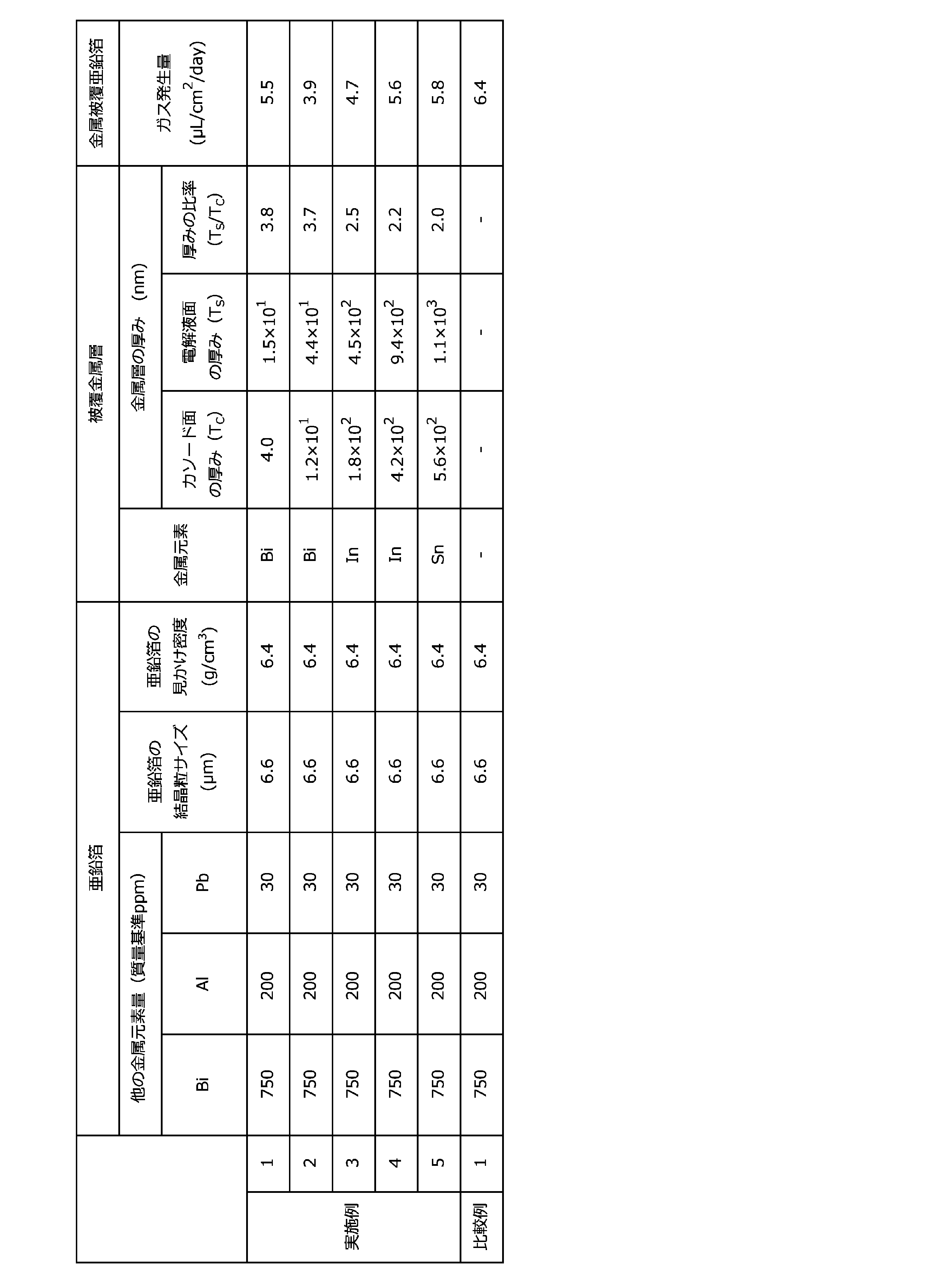
表1に示す結果から明らかなとおり、各実施例で得られた金属層被覆亜鉛箔は、比較例の亜鉛箔に比べてガスの発生量が抑制されていることが分かる。
本発明によれば、特に薄型電池の負極活物質材料として用いた場合に、その電池において、ガス発生量がこれまでよりも抑制された負極活物質材料用の亜鉛箔が提供される。
Claims (20)
- 亜鉛を母材とする箔本体と、該箔本体の表面に配置された金属層とを有する、金属層被覆亜鉛箔であって、
前記金属層に含まれる金属元素が、ビスマス、インジウム、アルミニウム、ガリウム、スズ、銀及びマンガンからなる群より選択される少なくとも一種である、金属層被覆亜鉛箔。 - 前記金属層に含まれる前記金属元素が、ビスマス、インジウム及びスズの少なくとも一種である、請求項1に記載の金属層被覆亜鉛箔。
- 前記金属層に含まれる前記金属元素が、ビスマス及びインジウムの少なくとも一種である、請求項1又は2に記載の金属層被覆亜鉛箔。
- 前記金属層の厚みが、5.0×10⁻¹nm以上3.0×10³nm以下である、請求項1ないし3のいずれか一項に記載の金属層被覆亜鉛箔。
- 前記金属層が、前記箔本体の表面の片面又は両面に配置される請求項1ないし4のいずれか一項に記載の金属層被覆亜鉛箔。
- 前記金属層が前記箔本体の両面に配置され、前記金属層の厚みが、一方の面と他方の面とで異なる請求項5に記載の金属層被覆亜鉛箔。
- 前記箔本体が電解箔である、請求項1ないし6のいずれか一項に記載の金属層被覆亜鉛箔。
- 前記金属層の一方の面の厚み(TC)に対する他方の面の厚み(TS)の比率(TS/TC)が2以上である請求項7に記載の金属層被覆亜鉛箔。
- 前記箔本体が、亜鉛を母材とし、亜鉛以外の金属元素を含む、請求項1ないし8のいずれか一項に記載の金属層被覆亜鉛箔。
- 前記箔本体に含まれる前記金属元素が、ビスマス、インジウム、アルミニウム、マグネシウム、カルシウム、ガリウム、スズ、バリウム、ストロンチウム、銀及びマンガンからなる群より選択される少なくとも一種である、請求項9に記載の金属層被覆亜鉛箔。
- 前記箔本体に含まれる前記金属元素が、ビスマスである、請求項9又は10に記載の金属層被覆亜鉛箔。
- 前記箔本体に含まれる前記金属元素の含有割合が、前記箔本体に対して質量基準で10ppm以上10000ppm以下である、請求項1ないし11のいずれか一項に記載の金属層被覆亜鉛箔。
- 請求項1ないし12のいずれか一項に記載の金属層被覆亜鉛箔の製造方法であって、亜鉛を母材とする箔本体の表面に被覆形成手段によって、ビスマス、インジウム、アルミニウム、ガリウム、スズ、銀及びマンガンからなる群より選択される少なくとも一種である金属元素を含む金属層を形成する、金属層被覆亜鉛箔の製造方法。
- 前記被覆形成手段が置換めっき法である、請求項13に記載の製造方法。
- 前記箔本体を、ビスマス、インジウム、アルミニウム、ガリウム、スズ、銀及びマンガンからなる群より選択される少なくとも一種の金属元素のイオンを含む置換めっき液に浸漬させる、請求項13又は14に記載の製造方法。
- 前記置換めっき液に含まれるイオンとなる金属元素が、ビスマス及びインジウムの少なくとも一種である、請求項15に記載の製造方法。
- 前記被覆形成手段が電気めっき法である、請求項13に記載の製造方法。
- 前記箔本体を、ビスマス、インジウム、アルミニウム、ガリウム、スズ、銀及びマンガンからなる群より選択される少なくとも一種である金属元素のイオンを含む電気めっき液に浸漬させ、所定の厚みを有する該金属元素を含む層が形成されるように通電する、請求項13又は17に記載の製造方法。
- 前記電気めっき液に含まれるイオンとなる金属元素が、ビスマス及びインジウムの少なくとも一種である、請求項18に記載の製造方法。
- 請求項1ないし12のいずれか一項に記載の金属層被覆亜鉛箔を用いた、電池用負極活物質材料。
Priority Applications (1)
| Application Number | Priority Date | Filing Date | Title |
|---|---|---|---|
| JP2022536471A JP7796015B2 (ja) | 2020-07-17 | 2021-07-19 | 金属層被覆亜鉛箔及びその製造方法 |
Applications Claiming Priority (2)
| Application Number | Priority Date | Filing Date | Title |
|---|---|---|---|
| JP2020-122670 | 2020-07-17 | ||
| JP2020122670 | 2020-07-17 |
Publications (1)
| Publication Number | Publication Date |
|---|---|
| WO2022014720A1 true WO2022014720A1 (ja) | 2022-01-20 |
Family
ID=79554714
Family Applications (1)
| Application Number | Title | Priority Date | Filing Date |
|---|---|---|---|
| PCT/JP2021/026995 Ceased WO2022014720A1 (ja) | 2020-07-17 | 2021-07-19 | 金属層被覆亜鉛箔及びその製造方法 |
Country Status (2)
| Country | Link |
|---|---|
| JP (1) | JP7796015B2 (ja) |
| WO (1) | WO2022014720A1 (ja) |
Cited By (3)
| Publication number | Priority date | Publication date | Assignee | Title |
|---|---|---|---|---|
| JP7466069B1 (ja) * | 2023-03-13 | 2024-04-11 | 三井金属鉱業株式会社 | 亜鉛箔及びその製造方法 |
| WO2024189937A1 (ja) * | 2023-03-13 | 2024-09-19 | 三井金属鉱業株式会社 | 亜鉛箔及びその製造方法 |
| CN120303784A (zh) * | 2023-06-30 | 2025-07-11 | 三井金属矿业株式会社 | 金属箔 |
Citations (6)
| Publication number | Priority date | Publication date | Assignee | Title |
|---|---|---|---|---|
| JPS62241260A (ja) * | 1986-04-10 | 1987-10-21 | Matsushita Electric Ind Co Ltd | アルカリ電池 |
| JPH05174813A (ja) * | 1991-12-26 | 1993-07-13 | Shin Kobe Electric Mach Co Ltd | 亜鉛陰極板及びその製造方法並びに亜鉛−二酸化鉛蓄電池 |
| JP2010504428A (ja) * | 2006-09-20 | 2010-02-12 | ザ クイーンズ ユニバーシティ オブ ベルファスト | 金属品を調整された濡れ性を有する表面で被覆する方法 |
| JP2010518585A (ja) * | 2007-02-12 | 2010-05-27 | パワージェニックス システムズ, インコーポレーテッド | 金属亜鉛型電流コレクタ |
| JP2015072832A (ja) * | 2013-10-03 | 2015-04-16 | 株式会社日本触媒 | 亜鉛負極用組成物及び亜鉛負極 |
| WO2020071350A1 (ja) * | 2018-10-03 | 2020-04-09 | 三井金属鉱業株式会社 | 亜鉛箔、これを用いた一次電池用負極活物質材料及び亜鉛箔の製造方法 |
-
2021
- 2021-07-19 WO PCT/JP2021/026995 patent/WO2022014720A1/ja not_active Ceased
- 2021-07-19 JP JP2022536471A patent/JP7796015B2/ja active Active
Patent Citations (6)
| Publication number | Priority date | Publication date | Assignee | Title |
|---|---|---|---|---|
| JPS62241260A (ja) * | 1986-04-10 | 1987-10-21 | Matsushita Electric Ind Co Ltd | アルカリ電池 |
| JPH05174813A (ja) * | 1991-12-26 | 1993-07-13 | Shin Kobe Electric Mach Co Ltd | 亜鉛陰極板及びその製造方法並びに亜鉛−二酸化鉛蓄電池 |
| JP2010504428A (ja) * | 2006-09-20 | 2010-02-12 | ザ クイーンズ ユニバーシティ オブ ベルファスト | 金属品を調整された濡れ性を有する表面で被覆する方法 |
| JP2010518585A (ja) * | 2007-02-12 | 2010-05-27 | パワージェニックス システムズ, インコーポレーテッド | 金属亜鉛型電流コレクタ |
| JP2015072832A (ja) * | 2013-10-03 | 2015-04-16 | 株式会社日本触媒 | 亜鉛負極用組成物及び亜鉛負極 |
| WO2020071350A1 (ja) * | 2018-10-03 | 2020-04-09 | 三井金属鉱業株式会社 | 亜鉛箔、これを用いた一次電池用負極活物質材料及び亜鉛箔の製造方法 |
Cited By (4)
| Publication number | Priority date | Publication date | Assignee | Title |
|---|---|---|---|---|
| JP7466069B1 (ja) * | 2023-03-13 | 2024-04-11 | 三井金属鉱業株式会社 | 亜鉛箔及びその製造方法 |
| WO2024189937A1 (ja) * | 2023-03-13 | 2024-09-19 | 三井金属鉱業株式会社 | 亜鉛箔及びその製造方法 |
| US12577639B2 (en) * | 2023-03-13 | 2026-03-17 | Mitsui Kinzoku Company, Limited | Zinc foil and method for producing the same |
| CN120303784A (zh) * | 2023-06-30 | 2025-07-11 | 三井金属矿业株式会社 | 金属箔 |
Also Published As
| Publication number | Publication date |
|---|---|
| JPWO2022014720A1 (ja) | 2022-01-20 |
| JP7796015B2 (ja) | 2026-01-08 |
Similar Documents
| Publication | Publication Date | Title |
|---|---|---|
| JP7081056B2 (ja) | 亜鉛箔及びこれを用いた電池用負極活物質材料、並びに亜鉛箔の製造方法 | |
| JP7796015B2 (ja) | 金属層被覆亜鉛箔及びその製造方法 | |
| CN112840053B (zh) | 锌箔、使用了其的一次电池用负极活性物质材料和锌箔的制造方法 | |
| US10396363B2 (en) | Copper foil, negative electrode current collector and negative electrode material for non-aqueous secondary battery | |
| Nikoloski et al. | Novel lead–cobalt composite anodes for copper electrowinning | |
| Liu et al. | Energy efficient electrodeposition of metallic manganese in an anion-exchange membrane electrolysis reactor using Ti/IrO2–RuO2–SiO2 anode | |
| TW201437434A (zh) | 電解銅箔及其製造方法 | |
| Yang et al. | The effects of SeO2 additive on Mn electrodeposition on Al substrate in MnSO4-(NH4) 2SO4-H2O solution | |
| JP6553558B2 (ja) | 表面処理銅箔、負極集電体及び非水系二次電池の負極材 | |
| TW201728764A (zh) | 電解銅箔以及使用該電解銅箔之鋰離子二次電池 | |
| CN117255875A (zh) | 集电体用表面处理钢箔及其制造方法 | |
| JP2015076224A (ja) | アルミニウム空気電池 | |
| WO2022054597A1 (ja) | 電解銅箔、リチウムイオン二次電池用負極、及びリチウムイオン二次電池 | |
| EP1079005A1 (en) | Dispersion-strengthened electrolytic cupper foil and method for producing the same | |
| US20260121074A1 (en) | Metal foil | |
| US12577639B2 (en) | Zinc foil and method for producing the same | |
| JP2023029245A (ja) | 有機物層被覆亜鉛箔及びその製造方法 | |
| WO2024189937A1 (ja) | 亜鉛箔及びその製造方法 | |
| JP6803566B2 (ja) | 銅三次元ナノ構造体の製造方法 | |
| JP2023044635A (ja) | 亜鉛箔及びその製造方法、負極材料並びに電池 | |
| JP2015076221A (ja) | アルミニウム空気電池の負極材用アルミニウム合金及びアルミニウム空気電池 | |
| JP6259310B2 (ja) | 亜鉛電極、亜鉛空気電池および電析方法 | |
| JP2019173104A (ja) | Coアノード及びCoアノードを用いた電気Coめっき方法 | |
| Stefanov et al. | Investigations of composite coatings used as anodes for zinc electroextraction from sulphate electrolytes | |
| JPH01279799A (ja) | 電気ZnメッキにおけるZnイオンの供給方法 |
Legal Events
| Date | Code | Title | Description |
|---|---|---|---|
| 121 | Ep: the epo has been informed by wipo that ep was designated in this application |
Ref document number: 21843154 Country of ref document: EP Kind code of ref document: A1 |
|
| ENP | Entry into the national phase |
Ref document number: 2022536471 Country of ref document: JP Kind code of ref document: A |
|
| NENP | Non-entry into the national phase |
Ref country code: DE |
|
| 122 | Ep: pct application non-entry in european phase |
Ref document number: 21843154 Country of ref document: EP Kind code of ref document: A1 |