WO2022014594A1 - 物品供給装置、サーバ及びユーザ端末 - Google Patents
物品供給装置、サーバ及びユーザ端末 Download PDFInfo
- Publication number
- WO2022014594A1 WO2022014594A1 PCT/JP2021/026312 JP2021026312W WO2022014594A1 WO 2022014594 A1 WO2022014594 A1 WO 2022014594A1 JP 2021026312 W JP2021026312 W JP 2021026312W WO 2022014594 A1 WO2022014594 A1 WO 2022014594A1
- Authority
- WO
- WIPO (PCT)
- Prior art keywords
- supply device
- article
- payment
- unit
- article supply
- Prior art date
- Legal status (The legal status is an assumption and is not a legal conclusion. Google has not performed a legal analysis and makes no representation as to the accuracy of the status listed.)
- Ceased
Links
Images



Classifications
-
- G—PHYSICS
- G06—COMPUTING OR CALCULATING; COUNTING
- G06Q—INFORMATION AND COMMUNICATION TECHNOLOGY [ICT] SPECIALLY ADAPTED FOR ADMINISTRATIVE, COMMERCIAL, FINANCIAL, MANAGERIAL OR SUPERVISORY PURPOSES; SYSTEMS OR METHODS SPECIALLY ADAPTED FOR ADMINISTRATIVE, COMMERCIAL, FINANCIAL, MANAGERIAL OR SUPERVISORY PURPOSES, NOT OTHERWISE PROVIDED FOR
- G06Q20/00—Payment architectures, schemes or protocols
- G06Q20/08—Payment architectures
- G06Q20/12—Payment architectures specially adapted for electronic shopping systems
-
- G—PHYSICS
- G06—COMPUTING OR CALCULATING; COUNTING
- G06Q—INFORMATION AND COMMUNICATION TECHNOLOGY [ICT] SPECIALLY ADAPTED FOR ADMINISTRATIVE, COMMERCIAL, FINANCIAL, MANAGERIAL OR SUPERVISORY PURPOSES; SYSTEMS OR METHODS SPECIALLY ADAPTED FOR ADMINISTRATIVE, COMMERCIAL, FINANCIAL, MANAGERIAL OR SUPERVISORY PURPOSES, NOT OTHERWISE PROVIDED FOR
- G06Q20/00—Payment architectures, schemes or protocols
- G06Q20/30—Payment architectures, schemes or protocols characterised by the use of specific devices or networks
- G06Q20/32—Payment architectures, schemes or protocols characterised by the use of specific devices or networks using wireless devices
-
- G—PHYSICS
- G07—CHECKING-DEVICES
- G07F—COIN-FREED OR LIKE APPARATUS
- G07F7/00—Mechanisms actuated by objects other than coins to free or to actuate vending, hiring, coin or paper currency dispensing or refunding apparatus
- G07F7/08—Mechanisms actuated by objects other than coins to free or to actuate vending, hiring, coin or paper currency dispensing or refunding apparatus by coded identity card or credit card or other personal identification means
-
- G—PHYSICS
- G07—CHECKING-DEVICES
- G07F—COIN-FREED OR LIKE APPARATUS
- G07F9/00—Details other than those peculiar to special kinds or types of apparatus
Definitions
- the present invention relates to an article supply device, a server and a user terminal.
- Patent Document 1 discloses an article supply device capable of paying a price by inserting a coin.
- the present invention is an article supply device capable of supplying an article, which is accommodated in an article accommodating portion for accommodating an article, a supply port for supplying an article accommodated in the article accommodating portion, and an article accommodating portion.
- An operation unit capable of accepting an operation for supplying the article to the supply port, and a control unit controlling the operation unit to allow or prohibit the acceptance of the operation according to the payment of the price of the article.
- the control unit controls the operation unit to accept the operation in response to the payment of the price by at least one of the first payment method and the second payment method. Includes one control mechanism.
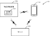
- FIG. 1 is a block diagram showing an example of the configuration of the system 10 according to the embodiment.
- the system 10 is configured by connecting the article supply device 100, the user terminal 110, and the server 120 so as to be able to communicate with each other. It was
- the user terminal 110 is, for example, a smartphone, and when the QR code (registered trademark) for payment attached to the goods supply device 100 is read by the built-in camera, the user terminal 110 accesses the server 120 via the link destination URL embedded in the QR code. Send the request.
- the QR code may be displayed as QR code information on the liquid crystal display unit.
- the server 120 provides the information on the goods purchase screen to the user terminal 110 in response to the access request. Information about the article housed in the article supply device 100 is displayed on the screen. Further, when the user of the user terminal 110 operates the payment button on the screen to give a payment instruction, the payment instruction is transmitted from the user terminal 110 to the server 120. Since a known technique may be used for the payment method, detailed description thereof will be omitted here. It was
- the unlock signal is transmitted from the server 120 to the article supply device 100, and the article supply device 100 releases the locked state of the handle arranged in the center and rotates the handle. It is possible to take out the product.
- the lock of the handle can also be released by inserting cash, and when it is confirmed that a predetermined amount of cash has been inserted, the handle lock is released and the handle can be turned. It was
- FIG. 2 is a diagram showing an example of the front appearance of the article supply device 100 corresponding to the embodiment. It was
- the main body of the article supply device 100 is composed of a front wall, a rear wall, and a side wall
- the article storage unit 200 is a container (or bucket) in which articles supplied from the article supply device 100 are stored. , Case, etc.).
- the article accommodating portion 200 may be made of transparent plastic and may be configured so that the articles accommodating inside can be visually recognized from the outside.
- the article for example, a toy, an electronic device, a doll, or the like is encapsulated and accommodated in the article accommodating section 200. Alternatively, it may be contained in a state where it is not encapsulated. It was
- the article accommodating unit 200 is installed above the main body unit 201, and an article transport mechanism for taking out the article from the article accommodating unit 200 and transporting the article to the take-out port 204 is arranged in the main body unit 201.
- a handle 202, a cash input port 203, an outlet 204, a cash return port 205, a cash return button 206, a barcode 207, and a QR code 101 are arranged on the front surface of the main body 201. It was
- the handle 202 is an operating member configured to be rotatable in the direction of an arrow in response to payment of a price, and the article is supplied to the outlet 204 when the user rotates the handle 202.
- the rotation of the handle 202 is suppressed by the lock mechanism when the payment of the price cannot be confirmed, and when the payment of the price is confirmed, the lock mechanism is released and the handle 202 can rotate.
- the cash slot 203 is used for inserting coins when the price is paid in cash, and there may be a plurality of types of cash slots depending on the size of the cash.
- FIG. 2 shows an insertion slot into which a 500-yen coin and a 100-yen coin can be inserted as an example.
- the cash input port 203 can switch between a state of accepting cash input and a state of not accepting cash input by controlling an internal mechanism. For example, when the entire price is paid by electronic money, cash may not be accepted by closing the slot. This can prevent double payment. It was
- the outlet 204 is a portion for taking out the supplied article by turning the handle 202, and is covered with a transparent or translucent lid, and the lid can be opened to take out the article.
- the cash return port 205 is configured so that the inserted coins are returned in response to the operation of the cash return button 206, and the coins returned from the outside of the device can be taken out.
- the operation of the cash return button 206 may not be accepted.
- the operation of the cash return button 206 is accepted, and if the operation is accepted, the entire amount of the inserted amount is returned. You may.
- the operation of the cash return button 206 will be accepted, and if the operation is accepted, part or all of the inserted amount will be returned. You may. At this time, a part of the input amount to be returned can be an excess amount. It was
- the bar code 207 is affixed to the surface of the article supply device 100 together with the QR code 101 described above, and information on the sales machine code for identifying the sales machine is registered.
- the vending machine code is mainly used by the administrator of the article supply device 100, and is registered in the server 120 in advance in association with the article code that identifies the article before the start of use. As a result, the server 120 can associate the QR code 101 with the article information in advance.
- the vending machine code may be embedded in the QR code and only the QR code may be attached. It was
- FIG. 3A is a diagram showing an example of the hardware configuration of the article supply device 100 corresponding to the embodiment.
- FIG. 3B is a diagram showing an example of the hardware configuration of the user terminal 110 corresponding to the embodiment.
- FIG. 3C is a diagram showing an example of the hardware configuration of the server 120 corresponding to the embodiment. It was
- the CPU 301 reads out various programs and data stored in the ROM 302 to realize predetermined control.
- the control includes a control for unlocking the handle 202 by the lock mechanism 306 according to the payment information of the price.
- the RAM 303 functions as a work area or the like.
- the communication unit 304 communicates with the server 120 to acquire information (payment information) as to whether or not the price has been paid by electronic money. When the communication unit 304 acquires the payment information, the communication unit 304 provides the information to the CPU 301, and the CPU 301 unlocks the handle 202 by the lock mechanism 306. It was
- the coin detection unit 305 detects whether or not a coin has been inserted from the cash insertion slot 203, and transmits a detection signal to the CPU 301 when the coin is inserted.
- the coin detection unit 305 includes an optical sensor.
- the CPU 301 receives the detection signal from the coin detection unit 305, the CPU 301 determines whether or not the detection signal has been received a number of times corresponding to the price, and releases the lock mechanism 306 according to the determination result. Further, the coin detection unit 305 detects the authenticity of the coin, and when the coin is detected, notifies the CPU 301 of an error. It was
- the lock mechanism 306 is a mechanism that suppresses (locks) the rotation of the handle 202, and has two states, a locked state and an unlocked state of the handle.
- the lock mechanism 306 includes a signal receiving unit 306a that receives a control signal instructing the transition (unlocking) from the locked state to the unlocked state from the CPU 301. Further, the lock mechanism 306 has a solenoid 306b.
- the signal receiving unit 306a receives the control signal
- the signal receiving unit 306a supplies a current to the solenoid 306b to drive the solenoid 306b, and releases the lock that suppresses the rotation of the handle 202. If the lock cannot be released even after receiving the control signal, it is determined that the lock is in an abnormal state, and an error notification is sent to the CPU 301. It was
- the article transport mechanism 307 is a transport mechanism for transporting one article to be supplied from the article accommodating unit 200 to the outlet 204 in response to the rotation of the handle 202 due to unlocking.
- a state detection unit 307a for detecting the state of whether or not the article can be reliably transported is appropriately arranged, the article does not exist in the article accommodating section 200, and an obstacle in the transport path. It is possible to detect an abnormality such as the existence of. When an abnormal state is detected, an error notification is sent to the CPU 301.
- the display unit 308 is a display device that displays information about the article supply device 100, and may be, for example, a liquid crystal display device. The input amount may be displayed on the display unit 308, or an error may be displayed when an abnormality of the device is detected. It was
- the CPU 311 reads various programs and data stored in the ROM 312 to realize control of the user terminal 110.
- the control includes control of acquiring access destination information from the QR code captured by the image pickup unit 316 and transmitting an access request to the access destination server 120, and screen information received from the server 120 in response to the access request. It includes control to be displayed on the display unit 317, control to communicate with the server 120 according to the operation received by the screen information, and the like.
- a non-volatile storage device may be provided.
- the RAM 313 functions as a work area or the like. It was
- the communication unit 314 communicates with the server 120, and as described above, transmits an access request, receives screen information, transmits operation information, and the like.
- the operation unit 315 is an interface for receiving operations from the user of the user terminal 110, and includes a touch panel, buttons, switches, and the like.
- the image pickup unit 316 is a digital camera mechanism that acquires an image of a subject, and in the present embodiment, it is mainly used for photographing a QR code attached to the surface of the article supply device 100.
- the display unit 317 is a display, and can, for example, display an article purchase screen including article information received from the server 120 and accept a payment operation from the user. It was
- the CPU 321 reads various programs and data stored in the ROM 322 and the internal storage device 325 to realize control of the server 120.
- the control includes control of receiving an access request transmitted from the user terminal 110, control of transmitting screen information to the user terminal 110 in response to the access request, and electronic money in response to screen operation information from the user terminal 110.
- the control for performing the payment process by the electronic money, the control for notifying the goods supply device 100 of the completion of the payment of the price, and the like when the payment process by the electronic money is completed are included.
- the RAM 323 functions as a work area or the like. It was
- the communication unit 324 communicates with the user terminal 110 and the article supply device 100 to receive an access request, transmit screen information, receive operation information, notify the completion of payment of the price, and the like, as described above.
- the internal storage device 325 is a storage device such as a hard disk, and stores control information, application programs, various data, and the like.
- the display unit 326 is a display, and can display predetermined screen information, for example. Further, although omitted in FIG. 3C, an operation unit that accepts an operation from the user of the server 120 can be further provided, and the operation unit includes a button, a switch, a keyboard, a mouse, a touch panel, and the like. It was
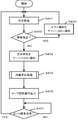
- FIG. 4 is a flowchart showing an example of processing corresponding to the embodiment.
- the process corresponding to FIG. 4 is realized by the CPU 301 executing the program stored in the ROM 302. It was
- the state of the article supply device 100 is detected.
- the CPU 301 determines whether or not an error notification notifying that an abnormality has been detected has been received from the coin detection unit 305, the lock mechanism 306, and the state detection unit 307a of the article transport mechanism 307.
- an abnormality is detected and an error notification is received (YES in S402)
- the process proceeds to S403, and the CPU 301 transmits the error notification to the server 120 via the communication unit 304.
- the server 120 cannot execute the payment process in relation to the article supply device 100 until the notification of the normal state is given.
- the process returns to S401, and the state detection is repeated until the normal state is reached. It was
- the process proceeds to S406, and the CPU 301 outputs the unlock signal to the lock mechanism 306.
- the unlock signal is received by the signal receiving unit 306a, and the solenoid 306b is driven to release the lock.
- the CPU 301 determines whether or not the lock mechanism 306 has returned from the unlocked state to the locked state based on whether or not a lock signal has been received from the lock mechanism 306.
- the process returns to S401. It was
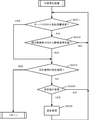
- the CPU 301 determines whether or not payment information has been received from the server 120. If the payment information has been received, the process proceeds to S503. On the other hand, if the payment information is not received from the server 120, the process proceeds to S502. In S502, the CPU 301 determines whether or not the detection signal has been received from the coin detection unit 305.
- the coin detection unit 305 has an optical sensor and transmits a detection signal to the CPU 301 each time a predetermined coin passes. Therefore, whether or not an amount corresponding to the price of the article, for example, 300 yen, has been paid can be determined by whether or not the detection signal has been received three times.
- the process proceeds to S503, and when not received, the process returns to S501. It was
- the CPU 301 determines whether or not the total payment amount has reached a predetermined amount corresponding to the price. If it is cash, it is determined based on whether or not the detection signal corresponding to the predetermined amount of money has been received. If it is electronic money, the determination is made based on the amount information included in the payment information. In the case of the total of cash and electronic money, the determination is made based on the total of the payment amount based on the number of times the detection signal is received and the payment amount included in the payment information. If the total amount is less than the predetermined amount, the process proceeds to S504, and if the total amount reaches the predetermined amount, the process proceeds to S406 in FIG.
- the cash return button 206 is operated to determine whether or not the cash return instruction has been accepted.
- the process proceeds to S505, and the inserted cash is returned. After that, the process returns to S501. If the return instruction is not accepted, the process returns to S501. It was
- the CPU 301 controls to close the cash slot 203 so that no additional coins are inserted.
- the CPU 301 controls to open the cash slot 203 and controls to additionally insert coins.
- the cash slot 203 is not provided with an opening / closing mechanism, in the former case, coins inserted in the cash slot 203 may be controlled to be returned as they are without being accepted, and in the latter case, the coins may be returned as they are. , The coins inserted in the cash slot 203 may be controlled to be accepted without being returned. It was
- the price can be paid in any form of cash only, electronic money only, and the total of cash and electronic money.
- the total of cash and electronic money it does not matter whether the cash is paid first or the electronic money is paid first. It was
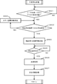
- This process is realized by the CPU 321 of the server 120 executing a program stored in an internal storage device 325 such as a ROM 321 or a hard disk. It was
- the CPU 321 determines whether or not an access request based on the QR code has been received from the user terminal 110.
- the access request contains information that identifies the article supply device 100. If the access request is received, the process proceeds to S602.
- the CPU 321 determines whether or not the corresponding article supply device 100 is in a normal state. If it is in the normal state, the process proceeds to S603. On the other hand, if it is in an abnormal state, the process proceeds to S604.
- the operating state of the article supply device 100 can be determined based on the notification in S403 or S404 of FIG. It was
- the CPU 321 controls the communication unit 324 to transmit information for displaying the article purchase screen from the server 120 to the user terminal 110.
- the article purchase screen includes at least information (article information) regarding the article to be purchased contained in the article storage unit 200.
- the article supply device 100 and the article housed in the device are managed in association with each other in the internal storage device 325 in advance. Therefore, even if the article housed in the article supply device 100 is changed, it is sufficient to change the association in the internal storage device 325. Therefore, even when the server 120 is accessed based on the same QR code, the information of the current article can be provided to the user terminal 110 by the association.
- the article information includes the name, image, description, price, etc. of the article.
- the price of the goods (purchase price) is presented on the goods purchase screen, the type of electronic money to be paid can be selected, and the payment amount can be set. It was
- the entire amount can be paid by electronic money, of course, a part may be paid by electronic money, and the rest may be paid by cash.
- the payment amount can be entered.
- the balance information may be provided from the article supply device 100 to the server 120, and the balance information may be presented on the screen.
- a payment button for giving a payment instruction is displayed on the goods purchase screen. After determining the payment amount and the type of electronic money to be used, the user of the user terminal 110 can tap the payment button. It was
- the CPU 321 controls the communication unit 324 and transmits information for displaying an error screen from the server 120 to the user terminal 110.
- the error screen includes at least information (article information) regarding the goods to be purchased contained in the goods storage unit 200.
- the article information includes the name, image, description, price, etc. of the article.
- the price of the goods (purchase price) is presented on the error screen, but the payment button is not displayed or the operation is not accepted because it is grayed out.
- a message indicating that payment by electronic money is not accepted may be displayed. After that, the process returns to S502 and monitors whether the article supply device 100 is in a normal state. It was
- FIG. 7 shows an example of information on the goods purchase screen.
- FIG. 7A shows an example of the display state of the goods purchase screen that can accept payment instructions by electronic money.
- FIG. 7B shows an example of the display state of the goods purchase screen that cannot accept the payment instruction by electronic money as the above-mentioned error screen. It was
- FIG. 7A an article image 701 showing the appearance of one of the plurality of types of articles housed in the article accommodating section 200 is displayed, and the indicator 702 displays the next article on the display screen. It has been shown to be switchable. When the user taps on the indicator 702, the current display screen is slid out to the left, and the display screen displaying the next article is slid in from the right side to switch. It was
- the display 704 displays the amount of the price of the article. If cash has already been inserted in the article supply device 100, the deducted amount may be displayed. For example, if the price is 500 yen and 200 yen has already been invested, 300 yen will be displayed. It should be noted that the fact that 200 yen has been invested may be displayed on the screen. It was
- the payment button 705 is operably displayed as shown in FIG. 7A if it is possible to receive a payment instruction. When it is impossible to accept the payment instruction, it is grayed out as shown in FIG. 7B and the operation instruction is not accepted. The grayout display is eliminated when the abnormal state of the article supply device 100 is resolved. It was
- the CPU 321 determines whether or not the payment operation instruction has been accepted in the subsequent S605.
- a payment instruction is given to the user terminal 1 together with information on the payment amount and the electronic money to be used. It is transmitted from 10 to the server 120.
- the server 120 receives the payment instruction, the process proceeds to S606, and the CPU 321 executes the payment process. Since the details of the payment process are publicly known techniques, detailed description thereof will be omitted.
- the CPU 321 controls the communication unit 324 in S607 to transmit payment information notifying that the payment is completed to the goods supply device 100.
- the payment information may include information on the amount of money for which payment has been completed.
- the CPU 301 of the goods supply device 100 confirms that the payment of all or part of the price has been completed.
- the lock mechanism 306 in the present embodiment is a single control mechanism common to both payment methods capable of releasing the handle lock in both cash payment and electronic money payment. It was
- the lock mechanism 306 includes a gear portion in which power by operating the handle 202, which is an operation portion, is directly or indirectly transmitted, and a lock mechanism portion provided in the vicinity of the gear portion.
- the gear portion is provided with a protrusion portion and an engaging portion.
- the lock mechanism portion is configured by connecting the first lever portion to the solenoid portion. The first lever portion is pushed outward from the lock mechanism portion by the urging of the spring inside the solenoid portion, and engages with the engaging portion to form an engaged state with the gear portion. In this engaged state, the first lever portion suppresses the rotation of the operation portion via the gear portion. It was
- the solenoid unit sends a current to the internal solenoid structure in response to the reception of the unlock signal from the CPU 301.
- the engagement state with the gear portion is released.
- the operation unit becomes rotatable and shifts from the locked state to the unlocked state.
- the locking mechanism portion further includes a second lever portion for releasing the unlocked state.
- the solenoid portion cuts off the current transmission to the solenoid structure.
- the first lever portion operates so as to be pushed out of the lock mechanism portion by the urging of the internal spring, and re-engages with the engaging portion of the gear portion.
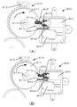
- the lock mechanism 306 includes a lock mechanism portion 800 and a gear portion 810.
- the lock mechanism unit 800 includes a solenoid unit 801, a lock lever 802, a non-lock state release lever 803, and a non-lock state release detection unit 804, and the gear unit 810 includes a large gear 811 and a small gear 812.
- the lock lever 802 that functions as the first lever portion operates to switch between a locked state that limits the rotation of the large gear 811 and a non-locked state that allows rotation.
- the non-locked state release lever 803 that functions as the second lever portion operates so as to release the non-locked state and return to the locked state. It was
- the large gear 811 is configured to include a protrusion 811a, a shaft portion 811b, and an engaging portion (or a recess or a notch) 811c.
- the lock lever 802 fits into the engaging portion 811c, and the upper edge of the engaging portion 811c engages with the lock lever 802, thereby suppressing the rotation of the large gear 811.
- the large gear 811 is configured to be rotatable in the direction of an arrow about the shaft portion 811b, and a shaft connected to the handle 202 is inserted into the opening of the shaft portion 811b, and when the user rotates the handle 202, the power thereof is increased. Is transmitted to the large gear 811 via the shaft. It was
- the solenoid unit 801 When the solenoid unit 801 receives the unlock signal from the CPU 301, the solenoid unit 801 flows a current through the solenoid and operates so as to pull the plunger externally urged by the spring into the inside of the lock mechanism 306. Along with this, the lock lever 802 connected to the protrusion 801a at the tip of the plunger is pulled into the lock mechanism 306, the engagement state between the lock lever 802 and the edge of the engagement portion 811c is released, and the lock lever 802 is released from the locked state. Move to the locked state. FIG. 8B shows the unlocked state at this time. It was
- the non-locked state release lever 803 comes into contact with the protrusion 811a of the large gear 811 and is pushed down.
- the protrusion 804a of the non-lock state release detection unit 804 is also pushed down, so that the solenoid unit 801 is instructed to stop the solenoid current from the non-lock state release detection unit 804 in response to the push down of the protrusion 804a. do.
- the solenoid unit 801 stops the solenoid current, whereby the plunger is pushed out of the lock mechanism 306 by the force of the internal spring.
- the lock lever 802 is also pushed outward to press the side surface of the large gear 811. After that, when the large gear 811 rotates in the direction of the arrow according to the rotation of the handle 202 and reaches the position of the engaging portion 811c, the lock lever 802 is pushed out to the engaging portion 811c to engage with the edge of the engaging portion 811c. do. This returns to the locked state shown in FIG. 8 (A). It was
- the large gear 811 engages with the small gear 812 to transmit the rotational force of the handle 202 to further gears.
- the other gear is connected to, for example, a gear that rotates the turntable in the article accommodating portion 200, and one article is supplied from the article accommodating portion 200 by rotating the handle 202.
- the handle 202 is provided on the front side of the front wall of the main body of the article supply device 100, and the large gear 811, the small gear 812, and the lock mechanism 306 are provided inside the rear wall of the main body.
- the article accommodating unit 200 is configured to be able to accommodate new articles by pulling it toward the main body of the article supply device 100, and is configured to smoothly pull out the article accommodating unit 200. It was decided to be installed on the rear wall of the part. It was
- the single locking mechanism can be released and the goods can be supplied in response to the payment of the price by cash and / or electronic money. It was
- the coin detection unit 305 sends a detection signal to the CPU 301 each time it detects each coin, but when the number of coins corresponding to the price is detected, the coin detection unit 305 notifies the completion of payment. You may. In that case, when the insertion of coins is detected, the server 120 detects that fact and prohibits payment by electronic money. In this case, the goods purchase screen displayed on the user terminal 110 is as shown in FIG. 7B, and the payment button 705 is grayed out so that the payment instruction is not accepted. Alternatively, payment with electronic money is prohibited for a certain period after the coin is inserted, and payment using electronic money cannot be performed together.
- the goods supply device 100 notifies the server 120 that the cash has been returned, and the server 120 cancels the grayed out display of the goods purchase screen on the user terminal 110 in response to the receipt of the notification. ..
- the electronic money can be used again. It was
- the payment amount cannot be selected, and the amount corresponding to the price is paid in a lump sum.
- the coins may be automatically returned in advance, and the goods supply device 100 may notify the server 120 that the coins have been returned in full.
- the server 120 notifies the goods supply device 100 when the payment by electronic money is completed, and the cash input port 203 is closed under the control of the CPU 301 in response to the notification, and cash input is prohibited. Will be done. It was
Landscapes
- Business, Economics & Management (AREA)
- General Physics & Mathematics (AREA)
- Physics & Mathematics (AREA)
- Accounting & Taxation (AREA)
- Engineering & Computer Science (AREA)
- Strategic Management (AREA)
- General Business, Economics & Management (AREA)
- Theoretical Computer Science (AREA)
- Finance (AREA)
- Computer Networks & Wireless Communication (AREA)
- Control Of Vending Devices And Auxiliary Devices For Vending Devices (AREA)
- Financial Or Insurance-Related Operations Such As Payment And Settlement (AREA)
- Vending Machines For Individual Products (AREA)
Abstract
【課題】複数通りの代価の支払いを可能としつつ、構造を簡素化した物品供給装置を提供する。【解決手段】物品を供給可能な物品供給装置であって、物品を収容する物品収容部と、前記物品収容部に収容されている物品が供給される供給口と、前記物品収容部に収容されている前記物品を前記供給口に供給するための操作を受け付け可能な操作部と、前記物品の代価の支払いに応じて前記操作部による操作の受け付けを許可又は禁止するように制御する制御部とを備え、前記制御部は、第1の支払方法及び第2の支払方法とのうち、少なくともいずれかにより前記代価が支払われたことに応じて前記操作部を前記操作を受け付けるように制御する単一の制御機構を含む。
Description
本発明は、物品供給装置、サーバ及びユーザ端末に関する。
代価の支払いに応じて、物品を供給する物品供給装置がある。特許文献1は、代価の支払いをコインの投入により行うことができる物品供給装置を開示する。
代価の支払い方法は、コインの投入のみならず、電子マネーによる支払いも可能にすることが求められている。その一方で、複数通りの代価の支払い方法を可能とすることで装置の構造が複雑化するのは好ましくない。
そこで、複数通りの代価の支払いを可能としつつ、構造を簡素化した物品供給装置を提供する。
本発明は、物品を供給可能な物品供給装置であって、 物品を収容する物品収容部と、 前記物品収容部に収容されている物品が供給される供給口と、 前記物品収容部に収容されている前記物品を前記供給口に供給するための操作を受け付け可能な操作部と、 前記物品の代価の支払いに応じて前記操作部による操作の受け付けを許可又は禁止するように制御する制御部とを備え、 前記制御部は、第1の支払方法及び第2の支払方法とのうち、少なくともいずれかにより前記代価が支払われたことに応じて前記操作部を前記操作を受け付けるように制御する単一の制御機構を含む。
複数通りの代価の支払いを可能としつつ、構造を簡素化した物品供給装置を提供することができる。
以下、添付図面を参照して実施形態を詳しく説明する。なお、以下の実施形態は特許請求の範囲に係る発明を限定するものではなく、また実施形態で説明されている特徴の組み合わせの全てが発明に必須のものとは限らない。実施形態で説明されている複数の特徴うち二つ以上の特徴が任意に組み合わされてもよい。また、同一若しくは同様の構成には同一の参照番号を付し、重複した説明は省略する。
図1は、実施形態に係るシステム10の構成の一例を示すブロック図である。システム10は、物品供給装置100、ユーザ端末110、サーバ120が通信可能に接続されて構成される。
ユーザ端末110は、例えばスマートフォンであって、物品供給装置100に貼付された決済用のQRコード(登録商標)を内蔵カメラで読み取るとQRコードに埋め込まれたリンク先URLを介してサーバ120にアクセス要求を送信する。なお、QRコードは、物品供給装置100が液晶表示部を備える場合、当該液晶表示部にQRコード情報として表示されてもよい。サーバ120はアクセス要求に応じて物品購入画面の情報をユーザ端末110に提供する。当該画面には、物品供給装置100に収容されている物品に関する情報が表示される。また、画面中の支払ボタンをユーザ端末110のユーザが操作して支払指示を行うと、支払指示がユーザ端末110からサーバ120に送信される。当該支払手法については公知の技術を用いればよいので、ここでの詳細な説明は省略する。
電子マネーによる代価の支払いが完了すると、サーバ120から物品供給装置100にロック解除信号が送信され、物品供給装置100は、中央に配置されたハンドルのロック状態を解除して、ハンドルを回動して商品を取り出すことを可能とする。ハンドルのロックは現金投入によっても解除可能であって、所定金額の現金が投入されたことを確認すると同様にハンドルロックが解除されて、ハンドルを回すことが可能となる。
次に図2を参照して、物品供給装置100の外観構成について説明する。図2は、実施形態に対応する物品供給装置100の正面の外観の一例を示す図である。
図2において、物品供給装置100の本体部は、前壁、後壁、及び側壁から構成され、物品収容部200は、物品供給装置100より供給される物品が収容される収容器(或いは、バケツ、ケース等)である。物品収容部200は、透明なプラスチック製で、内部に収容されている物品を外部から視認可能に構成されてもよい。物品は、例えば、玩具、電子機器、人形などがカプセルに封入されて、物品収容部200に収容される。或いは、カプセルに封入されていない状態で収容されてもよい。
物品収容部200は、本体部201の上側に設置されており、本体部201内には、物品を物品収容部200から取り出して取出口204まで搬送し供給するための物品搬送機構が配置されている。本体部201の前面部には、ハンドル202、現金投入口203、取出口204、現金返却口205、現金返却ボタン206、バーコード207、QRコード101が配置されている。
ハンドル202は、代価の支払いに応じて矢印方向に回転可能に構成された操作部材であって、ユーザがハンドル202を回転させることにより、物品が取出口204に供給される。ハンドル202は、代価の支払いが確認できない状態ではロック機構により回転が抑制されており、代価の支払いが確認されるとロック機構が解除されて回転可能となる。
現金投入口203は、代価を現金で支払う場合に、硬貨を投入するのに用いられ、現金の大きさに応じて、複数種類の投入口があってもよい。図2は、一例として500円玉と100円玉とを挿入可能な挿入口を示している。現金投入口203は、内部の機構を制御することにより現金の投入を受け付ける状態と、受け付けない状態とを切り替えることができる。例えば、電子マネーにより代価の全額が支払われた場合には、投入口を閉じることで現金の投入を受け付けないようにしてもよい。これにより二重払いを防止することができる。
取出口204は、ハンドル202を回して供給された物品を取り出す部分であり、透明、或いは、半透明の蓋で覆われており、蓋を開けて物品を取り出すことができる。現金返却口205は、現金返却ボタン206の操作に応じて投入した硬貨が返却され、装置外部から返却された硬貨を取り出し可能に構成されている。ここで、物品の代価に相当する枚数の硬貨が投入されていた場合には、現金返却ボタン206の操作を受け付けないようにしてもよい。一方、物品の代価の一部に相当する枚数の硬貨が投入されていた場合には、現金返却ボタン206の操作を受け付けるようにして、操作を受け付けた場合には、投入金額の全額を返却してもよい。また、物品の代価を超過する枚数の硬貨が投入されていた場合には、現金返却ボタン206の操作を受け付けるようにして、操作を受け付けた場合には、投入金額の一部または全部を返却してもよい。このとき、返却する投入金額の一部は超過分とすることができる。
バーコード207は、上述のQRコード101と共に物品供給装置100の表面に貼付されており、販売機を識別するための販売機コードの情報が登録されている。販売機コードは、主に物品供給装置100の管理者により使用され、使用開始前に物品を特定する物品コードと関連付けてサーバ120に事前に登録しておく。これにより、サーバ120は、QRコード101と、物品情報とを予め関連付けておくことが可能となる。なお、QRコードとバーコード207を別々に設けずに、QRコードに販売機コードを埋め込んで、QRコードのみを貼付することで対応するようにしてもよい。
次に、図3を参照して、実施形態に対応する各装置のハードウェア構成の一例を説明する。図3(A)は、実施形態に対応する物品供給装置100のハードウェア構成の一例を示す図である。図3(B)は、実施形態に対応するユーザ端末110のハードウェア構成の一例を示す図である。図3(C)は、実施形態に対応するサーバ120のハードウェア構成の一例を示す図である。
図3(A)においてCPU301は、ROM302に記憶された各種プログラムとデータを読み出して所定の制御を実現する。当該制御には、代価の支払情報に応じて、ロック機構306によるハンドル202のロックを解除する制御が含まれる。RAM303は、ワークエリアなどとして機能する。通信部304は、サーバ120と通信して、代価の支払いが電子マネーにより行われたかどうかの情報(支払情報)を取得する。通信部304は支払情報を取得するとCPU301に当該情報を提供し、CPU301はロック機構306によるハンドル202のロックを解除する。
硬貨検知部305は、硬貨が現金投入口203から投入されたかどうかを検知し、硬貨が投入されると検知信号をCPU301に送信する。硬貨検知部305は、光センサを含む。CPU301は、硬貨検知部305からの検知信号を受信すると、代価に相当する回数の検知信号を受信したかどうかを判定し、判定結果に従ってロック機構306を解除する。また、硬貨検知部305は、硬貨の真贋検知を行い、贋貨が検出されるとCPU301にエラー通知を行う。
ロック機構306は、ハンドル202の回転を抑制する(ロックする)機構であって、ハンドルのロック状態と非ロック状態との2つの状態を有する。ロック機構306は、CPU301からロック状態から非ロック状態への移行(ロック解除)を指示する制御信号を受信する信号受信部306aを備える。また、ロック機構306はソレノイド306bを有する。信号受信部306aは、当該制御信号を受信するとソレノイド306bに電流を供給して駆動し、ハンドル202の回転を抑制するロックを解除する。また、制御信号を受信してもロックが解除できない場合には、異常状態と判定し、CPU301にエラー通知を行う。
物品搬送機構307は、ロック解除によりハンドル202が回転されたことに応じて、物品収容部200から供給対象の物品1つを取出口204まで搬送するための搬送機構である。物品搬送機構307には、物品の搬送を確実に行えるかどうか、状態を検出する状態検出部307aが適宜配置されており、物品が物品収容部200に存在していないこと、搬送経路に障害物が存在すること等の異常を検知することができる。異常状態が検出されるとCPU301にエラー通知を行う。表示部308は、物品供給装置100に関する情報を表示する表示装置であって、例えば液晶ディスプレイ装置でもよい。表示部308には、投入された金額が表示されてもよいし、装置の異常が検知された場合にエラー表示がされてもよい。
図3(B)においてCPU311は、ROM312に記憶された各種プログラムとデータを読み出してユーザ端末110の制御を実現する。当該制御には、撮像部316で撮像したQRコードからアクセス先の情報を取得して当該アクセス先のサーバ120にアクセス要求を送信する制御や、アクセス要求に応じてサーバ120から受信した画面情報を表示部317に表示させる制御や、画面情報で受け付けた操作に応じてサーバ120と通信する制御等が含まれる。また、ROM312の他に、不揮発性の記憶装置を備えていてもよい。RAM313は、ワークエリアなどとして機能する。
通信部314は、サーバ120と通信して、上述のように、アクセス要求の送信、画面情報の受信、操作情報の送信等を行う。操作部315は、ユーザ端末110のユーザからの操作を受け付けるインタフェースであり、タッチパネルや、ボタン、スイッチ等を含む。撮像部316は、被写体の画像を取得するデジタルカメラ機構であり、本実施形態では、主に物品供給装置100の表面に貼付されているQRコードを撮影するために用いられる。表示部317はディスプレイであって、例えば、サーバ120から受信した物品情報が含まれる物品購入画面を表示して、ユーザからの支払操作を受け付けることができる。
図3(C)においてCPU321は、ROM322や内部記憶装置325に記憶された各種プログラムとデータを読み出してサーバ120の制御を実現する。当該制御には、ユーザ端末110から送信されたアクセス要求を受信する制御や、アクセス要求に応じてユーザ端末110に画面情報を送信する制御や、ユーザ端末110からの画面操作情報に応じて電子マネーによる決済処理を行う制御、電子マネーによる決済処理が完了すると、物品供給装置100に代価の支払完了を通知する制御等が含まれる。RAM323は、ワークエリアなどとして機能する。
通信部324は、ユーザ端末110や物品供給装置100と通信して、上述のように、アクセス要求の受信、画面情報の送信、操作情報の受信、代価の支払完了の通知等を行う。内部記憶装置325は、ハードディスク等の記憶装置であって、制御情報、アプリケーションプログラム、各種データ等を保存する。表示部326はディスプレイであって、例えば、所定の画面情報を表示することができる。また、図3(C)では省略したが、サーバ120のユーザからの操作を受け付ける操作部を更に備えることができ、当該操作部は、ボタン、スイッチ、キーボード、マウス、タッチパネル等を含む。
次に、図4を参照して、本実施形態に対応する処理の一例を説明する。図4は、実施形態に対応する処理の一例を示すフローチャートである。図4に対応する処理は、CPU301がROM302に記憶されたプログラムを実行することにより実現される。
まず、S401において、物品供給装置100の状態検出を行う。CPU301は、硬貨検知部305、ロック機構306、物品搬送機構307の状態検出部307aから異常が検出されたことを通知するエラー通知を受信したかどうかを判定する。異常検出がされエラー通知を受信した場合(S402でYES)、処理はS403に進み、CPU301は通信部304を介してサーバ120にエラー通知を送信する。これにより、サーバ120は、正常状態の通知がなされるまで、当該物品供給装置100との関連において支払処理を実行することができない。その後、処理はS401に戻り、正常状態になるまで状態検出を繰り返し行う。
異常が検出されなかった場合(S402でNO)、処理はS404に進み、CPU301は通信部304を介して、サーバ120に物品供給装置100が正常状態にあることの通知を送信する。続くS405において代価支払処理を実行する。代価支払処理の詳細は図5、図6のフローチャートを参照して後述する。
代価支払処理が完了し、CPU301は支払が完了したことを確認すると処理はS406に進み、CPU301はロック解除信号をロック機構306に出力する。当該ロック解除信号は信号受信部306aにより受信され、ソレノイド306bが駆動されてロックが解除される。続くS407において、CPU301は、ロック機構306がロック解除状態からロック状態に戻ったかどうかを、ロック機構306からロック信号を受信したかどうかに基づいて判定する。ロック信号を受信すると、処理はS401に戻る。
次に、図5を参照して、物品供給装置100側で実行される代価支払処理について説明する。当該処理は、CPU301がROM302に記憶されたプログラムを実行することにより実現される。
まず、S501において、CPU301は、サーバ120から支払情報を受信したかどうかを判定する。支払情報を受信していた場合、処理はS503に進む。一方、サーバ120から支払情報を受信していない場合、処理はS502に進む。S502では、CPU301は硬貨検知部305から検知信号を受信したかどうかを判定する。ここで硬貨検知部305は光センサを有し、所定の硬貨が1枚通過するたびに検知信号をCPU301に送信する。従って、物品の代価に相当する金額、例えば300円の支払いが行われたかどうかは、検知信号を3回受信したかどうかにより判定することができる。検知信号を受信すると処理はS503に進み、受信しない場合、処理はS501に戻る。
S503では、CPU301は支払合計金額が代価に相当する所定金額に達したかどうかを判定する。現金であれば、所定金額に相当する回数の検知信号を受信したかどうかに基づき判定する。電子マネーであれば、支払情報に含まれる金額情報に基づいて判定する。現金と電子マネーの合算の場合、検知信号の受信回数に基づく支払金額と、支払情報に含まれる支払金額との合計に基づいて判定する。合計金額が所定金額に満たない場合、処理はS504に進み、所定金額に達した場合、処理は図4のS406に進む。S504では、現金返却ボタン206が操作され、現金の返却指示を受け付けたかどうかを判定する。現金返却指示を受け付けた場合、処理はS505に進み、投入された現金の返却を行う。その後処理はS501に戻る。返却指示を受け付けない場合、処理はS501に戻る。
電子マネーにおいて代価の全部が支払われた場合、CPU301は、現金投入口203を閉じるように制御して、硬貨の投入が追加で行われないように制御する。一方、電子マネーにおいて代価の一部が支払われた場合、CPU301は、現金投入口203を開くように制御して、硬貨の投入が追加で行われるように制御する。なお、現金投入口203に開閉機構を設けない場合においては、前者の場合は、現金投入口203に投入された硬貨を受け付けることなく、そのまま返却するように制御してもよく、後者の場合は、現金投入口203に投入された硬貨を返却することなく受け付けるように制御してもよい。
以上のように本実施形態では、代価を現金のみ、電子マネーのみ、現金と電子マネーの合計のいずれかの形態で代価を支払うことができる。現金と電子マネーの合計の場合、現金を先に支払っても、電子マネーを先に支払っても、どちらでもよい。
次に図6を参照して、代価支払処理におけるサーバ120側の処理を説明する。当該処理は、サーバ120のCPU321がROM321やハードディスク等の内部記憶装置325に記憶されたプログラムを実行することにより実現される。
まず、S601において、CPU321は、ユーザ端末110からQRコードに基づくアクセス要求を受信したか否かを判定する。当該アクセス要求には、物品供給装置100を特定する情報が含まれている。もし、アクセス要求を受信した場合には、処理はS602に進む。S602において、CPU321は該当する物品供給装置100が正常状態であるかどうかを判定する。もし、正常状態である場合、処理はS603に進む。一方、異常状態である場合、処理はS604に進む。物品供給装置100における動作状態については、図4のS403またはS404における通知に基づいて判定することができる。
物品供給装置100が正常状態にある場合、S603において、CPU321は通信部324を制御して、サーバ120からユーザ端末110に対して、物品購入画面を表示するための情報を送信する。当該物品購入画面には、少なくとも物品収容部200に収容されている購入対象の物品に関する情報(物品情報)が含まれる。物品供給装置100と、当該装置に収容されている物品とは、予め内部記憶装置325内で関連付けて管理されている。従って、物品供給装置100内に収容されている物品が変更された場合であっても、内部記憶装置325内での関連付けを変更すれば足りる。よって、同一のQRコードに基づいてサーバ120にアクセスした場合であっても、当該関連付けにより、現在の物品の情報をユーザ端末110に提供することができる。物品情報には、物品の名称、画像、説明、価格等が含まれる。また、物品購入画面には、物品の代価(購入価格)が提示され、支払いを行う電子マネーの種類を選択することができると共に、支払金額を設定することができる。
例えば、全額を電子マネーにより支払うことができるのは勿論のこと、一部を電子マネーで支払い、残りを現金で支払うようにしてもよい。一部を電子マネーで支払う場合には、支払金額を入力することができる。或いは、先に現金を投入し残金を電子マネーで支払いする場合には、残金情報が物品供給装置100からサーバ120に提供され、画面上に残金情報が提示されてもよい。また、物品購入画面には、支払指示を行うための支払ボタンが表示される。ユーザ端末110のユーザは、支払金額や使用する電子マネーの種類を決定したら、支払ボタンをタップすることができる。
一方、物品供給装置100が異常状態にある場合、S604において、CPU321は通信部324を制御して、サーバ120からユーザ端末110に対して、エラー画面を表示するための情報を送信する。当該エラー画面には、少なくとも物品収容部200に収容されている購入対象の物品に関する情報(物品情報)が含まれる。当該物品情報には、物品の名称、画像、説明、価格等が含まれる。また、エラー画面には、物品の代価(購入価格)が提示されるが、支払ボタンは表示されないか、或いはグレーアウトにするなどして操作を受け付けない。また、電子マネーによる支払を受け付けていない旨のメッセージを表示してもよい。その後、処理はS502に戻って物品供給装置100が正常状態になったかどうかを監視する。
図7は、物品購入画面の情報の一例を示す。図7(A)は、電子マネーによる支払い指示を受け付け可能な物品購入画面の表示状態の一例を示す。図7(B)は、上述のエラー画面としての、電子マネーによる支払い指示を受け付け不可能な物品購入画面の表示状態の一例を示す。
図7(A)において、物品収容部200に収容されている複数の種類の物品の内の1つの物品の外観を示す物品画像701が表示され、指示器702により、次の物品の表示画面に切り替え可能なことが示されている。ユーザが当該指示器702の上をタップすると、現在の表示画面が左方向にスライドアウトされ、次の物品を表示する表示画面が右側からスライドインされて切り替わる。
表示領域703には、物品画像701の物品に関する情報(物品の名称や説明)が表示される。表示704は、物品の代価の金額が表示される。もし、物品供給装置100において既に現金が投入されている場合には、差し引きの金額が表示されてもよい。例えば、代価が500円の場合に、既に200円が投入されていれば300円の表示がなされることになる。なお、200円が投入されている旨が画面上に表示されてもよい。
支払いボタン705は、支払指示を受け付けることが可能であれば、図7(A)のように操作可能に表示される。支払指示を受け付けることが不可能な場合は図7(B)のようにグレーアウト表示され、操作指示を受け付けない。当該グレーアウト表示は、物品供給装置100の異常状態が解消されれば解消される。
図6に戻ってS603において物品購入画面情報が送信され、ユーザ端末110において支払金額及び使用する電子マネーの種類が決定されると、続くS605においてCPU321は支払操作指示を受け付けたかどうかを判定する。ユーザ端末110では、支払ボタンがタップされると、支払金額及び使用する電子マネーの情報と共に支払指示がユーザ端末1
10からサーバ120宛に送信される。サーバ120が支払指示を受信すると、処理はS606に進み、CPU321は決済処理を実行する。なお、決済処理の詳細については、公知技術であるので詳細な説明は省略する。決済処理が完了すると、S607においてCPU321は通信部324を制御して、支払完了の旨を通知する支払情報を物品供給装置100に送信する。支払情報には、支払が完了している金額の情報が含まれてもよい。物品供給装置100のCPU301は、支払情報をサーバ120から受信すると、代価の全部または一部の支払が完了したことを確認する。
10からサーバ120宛に送信される。サーバ120が支払指示を受信すると、処理はS606に進み、CPU321は決済処理を実行する。なお、決済処理の詳細については、公知技術であるので詳細な説明は省略する。決済処理が完了すると、S607においてCPU321は通信部324を制御して、支払完了の旨を通知する支払情報を物品供給装置100に送信する。支払情報には、支払が完了している金額の情報が含まれてもよい。物品供給装置100のCPU301は、支払情報をサーバ120から受信すると、代価の全部または一部の支払が完了したことを確認する。
次に、本実施形態に対応するロック機構306について説明する。本実施形態におけるロック機構306は、現金決済及び電子マネー決済のいずれの場合にもハンドルロックを解除可能な両決済方法に共通の単一の制御機構である。
ロック機構306は、操作部であるハンドル202に対する操作による動力が直接的又は間接的に伝達されるギア部と、当該ギア部の近傍に設けられたロック機構部とを含む。ギア部には、突起部と係合部とが設けられている。また、ロック機構部は、ソレノイド部に第1レバー部が接続されて構成されている。第1レバー部は、ソレノイド部内部のバネの付勢によりロック機構部から外側に押し出され、係合部と係合してギア部との係合状態を形成する。この係合状態において、第1レバー部はギア部を介して操作部の回転を抑制する。
ソレノイド部は、CPU301からのロック解除信号の受信に応じて、内部のソレノイド構造体に電流を送出する。当該電流の送出に応じて第1レバー部がロック機構部内に引き込まれるように動作することで、ギア部との係合状態が解除される。これにより、操作部が回転可能となりロック状態から非ロック状態に移行する。
ロック機構部は、非ロック状態を解除するための第2レバー部を更に含む。第2レバー部とギア部の突起部との接触を検知すると、ソレノイド部はソレノイド構造体に対する電流送出を遮断する。これに伴って内部のバネの付勢により第1レバー部がロック機構部の外側に押し出されるように動作し、ギア部の係合部と再び係合する。
以下、ロック機構306のより具体的な構成及び動作について図8を参照して説明する。図8(A)は、ロック機構306がロック状態にある場合を示し、図8(B)はロック機構306が非ロック状態にある場合を示している。ロック機構306は、ロック機構部800と、ギア部810とを含む。ロック機構部800は、ソレノイド部801、ロックレバー802、非ロック状態解除レバー803、非ロック状態解除検知部804を含み、ギア部810には、大ギア811と小ギア812とを含む。上記第1レバー部として機能するロックレバー802により、大ギア811の回転を制限するロック状態と、回転を許容する非ロック状態とを切り替えるように動作する。また、上記第2レバー部として機能する非ロック状態解除レバー803により、非ロック状態を解除してロック状態に復帰するように動作する。
大ギア811は、突起部811a、軸部811b、係合部(或いは、凹部、切欠部ともいう)811cを含むように構成されている。ロック状態においては、ロックレバー802が係合部811cに嵌り、係合部811cの上側の縁とロックレバー802とが係合することにより、大ギア811の回転が抑制される。大ギア811は、軸部811bを中心として矢印方向に回転可能に構成されており、軸部811bの開口には、ハンドル202と連結するシャフトが挿入され、ユーザがハンドル202を回転させるとその動力がシャフトを介して大ギア811に伝達される。
このとき、ロックレバー802が図8(B)に示すように大ギア811の係合部811cに嵌っていなければ大ギア811は回転するので、ハンドル202を回転させることができるが、図8(A)に示すように係合部811cに嵌っている場合には大ギア811は回転できないので、ハンドル202を回転させることができない。なお、図8では、ハンドル202に対する操作による動力が直接的に伝達される大ギア811に対してロックをかける構成としているが、これ以外にも、同様の構成を適用してハンドル202からの動力が間接的に伝達されるギア(例えば、小ギア812)をロックするようにしてもよい。
ソレノイド部801は、CPU301からロック解除信号を受信すると、ソレノイドに電流を流し、バネで外側に付勢されているプランジャーをロック機構306の内側に引き込むように動作する。これに伴ってプランジャー先端の突起部801aと接続されたロックレバー802がロック機構306内に引き込まれ、ロックレバー802と係合部811cの縁との係合状態が解除され、ロック状態から非ロック状態に移行する。図8(B)はこのときの非ロック状態を示している。
非ロック状態において大ギア811が矢印方向に回転すると、非ロック状態解除レバー803が大ギア811の突起部811aと接触して押し下げられる。これにより、非ロック状態解除検知部804の突起部804aも一緒に押し下げられるので、突起部804aの押し下げに応じて、非ロック状態解除検知部804からソレノイド部801にソレノイド電流を停止するように指示する。ソレノイド部801は、停止指示受け付けるとソレノイド電流を停止し、それにより内部のバネの力によって、プランジャーがロック機構306の外側に押し出される。それに伴って、ロックレバー802も同様に外側に押し出されて、大ギア811の側面を押圧する。その後、大ギア811がハンドル202の回転に応じて矢印方向に回転し、係合部811cの位置まで来ると、係合部811cにロックレバー802が押し出されて係合部811cの縁と係合する。これでまた図8(A)のロック状態に戻る。
大ギア811は小ギア812と係合して、ハンドル202の回転力を更に他のギアに伝達させる。当該他のギアは例えば物品収容部200内の回転盤を回転させるギヤに接続されており、ハンドル202が回転することにより、1つの物品が物品収容部200から供給されることになる。なお、ハンドル202は、物品供給装置100の本体部の前壁の表側に設けられ、大ギア811、小ギア812、及びロック機構306は、本体部の後壁の内側に設けられる。物品収容部200は、物品供給装置100の本体部に対し手前に引出すことで新たな物品を収容可能に構成されており、物品収容部200の引き出し動作をスムーズに行えるようにするために、本体部の後壁に設けることとしたものである。
このように、本実施形態においては、現金及び/又は電子マネーによる代価の支払いに応じて単一のロック機構を解除して物品を供給することができる。
<変形例> 上記において、硬貨検知部305は、硬貨1枚ごと検知するたびに検知信号をCPU301に対して送信していたが、代価に相当する枚数が検知された場合に、支払完了を通知してもよい。その場合、硬貨の投入が検知されるとサーバ120にその旨を検知して、電子マネーによる支払いを禁止する。この場合、ユーザ端末110に表示される物品購入画面は、図7(B)のようになり、支払ボタン705がグレーアウトされて支払指示を受け付けない状態となる。或いは、硬貨投入後の一定期間は電子マネーでの支払いを禁止し、電子マネーを併用した支払いが行えなくなる。電子マネーでの支払いを行うには、現金返却ボタン206の操作により現金が返却される必要がある。現金が返却されると、物品供給装置100からサーバ120に返却が行われた旨の通知がなされ、サーバ120は当該通知の受信に応じて、ユーザ端末110における物品購入画面のグレーアウト表示を解消する。或いは、ハンドル202を回して物品が供給されれば電子マネーが再度利用可能となる。
また、電子マネーでの支払いにおいては、支払金額を選択することができず、代価に相当する額を一括で支払うことになる。その際、事前に硬貨の返却を自動で行い、全額返却を行った旨を物品供給装置100からサーバ120に通知してもよい。自動返金動作を行うことで、現金と電子マネーの二重払いを防ぐことができる。また、二重払いを防止するため、電子マネーによる決済が完了した時点でサーバ120から物品供給装置100に通知がなされ、通知を受けてCPU301の制御により現金投入口203を閉じて現金投入が禁止される。
発明は上記の実施形態に制限されるものではなく、発明の要旨の範囲内で、種々の変形・変更が可能である。
Claims (21)
- 物品を供給可能な物品供給装置であって、 物品を収容する物品収容部と、 前記物品収容部に収容されている物品が供給される供給口と、 前記物品収容部に収容されている前記物品を前記供給口に供給するための操作を受け付け可能な操作部と、 前記物品の代価の支払いに応じて前記操作部による操作の受け付けを許可又は禁止するように制御する制御部とを備え、 前記制御部は、第1の支払方法及び第2の支払方法とのうち、少なくともいずれかにより前記代価が支払われたことに応じて前記操作部を前記操作を受け付けるように制御する単一の制御機構を含む、物品供給装置。
- 前記第1の支払方法は、硬貨による支払方法であり、前記第2の支払方法は、電子マネーによる支払方法である、請求項1に記載の物品供給装置。
- 前記単一の制御機構は、前記代価が支払われたことに応じて前記操作部に対するロックを解除することにより、前記操作部を前記操作を受け付けないロック状態から、前記操作を受け付け可能な非ロック状態に遷移させる、請求項2に記載の物品供給装置。
- 硬貨の投入を受け付ける硬貨投入口と、 前記硬貨投入口に投入された硬貨を検知する硬貨検知部とを更に備え、 前記制御部は、前記代価に相当する枚数の硬貨が前記硬貨検知部により検知されると、前記単一の制御機構に前記操作部に対するロックを解除させる、請求項3に記載の物品供給装置。
- 外部のサーバと通信する通信部を更に備え、 前記通信部が、前記サーバから電子マネーによる代価の全額の支払いが完了した旨の通知を受信すると、前記制御部は、前記単一の制御機構に前記操作部に対するロックを解除させる、請求項4に記載の物品供給装置。
- 前記通信部が、前記サーバから電子マネーによる代価の全額の支払いが完了した旨の通知を受信すると、前記制御部は硬貨の投入を受け付けないように前記硬貨投入口を制御する、請求項5に記載の物品供給装置。
- 外部のサーバと通信する通信部を更に備え、 前記代価の一部に相当する枚数の硬貨が前記硬貨検知部により検知された後、前記通信部が、前記サーバから電子マネーによる前記代価の残りの支払いが完了した旨の通知を受信すると、前記制御部は、前記単一の制御機構に前記操作部に対するロックを解除させる、請求項4に記載の物品供給装置。
- 外部のサーバと通信する通信部を更に備え、 前記通信部が、前記サーバから電子マネーによる代価の一部の支払いが完了した旨の通知を受信すると、前記制御部は硬貨の投入を受け付けるように前記硬貨投入口を制御し、 前記代価の残りに相当する枚数の硬貨が前記硬貨検知部により検知されると、前記制御部は、前記単一の制御機構に前記操作部に対するロックを解除させる、請求項4に記載の物品供給装置。
- 外部のサーバと通信する通信部を更に備え、 前記硬貨検知部により、前記投入された硬貨が検知されると、 前記通信部は前記サーバに対して、前記硬貨の検知を通知し、 前記サーバは、前記硬貨の検知の通知に応じて、前記物品供給装置に収容された前記物品に対する電子マネーによる代価の支払指示を受け付けない、請求項4に記載の物品供給装置。
- 前記物品供給装置に投入された硬貨を返金する返金部を更に備え、 前記返金部により前記投入された硬貨が全額返金された場合に、前記通信
部は硬貨の返金を前記サーバに通知し、 前記サーバは、前記硬貨の返金の通知に応じて、前記物品供給装置に収容されている前記物品に対する電子マネーによる代価の支払指示を受け付ける、請求項9に記載の物品供給装置。 - 前記返金部は、 前記物品供給装置に投入された硬貨の合計金額が前記代価に相当する額に満たない場合に、前記投入された硬貨を全額返金し、 前記物品供給装置に投入された硬貨の合計金額が前記代価に相当する額よりも大きい場合に、前記投入された硬貨のうち少なくとも一部の硬貨を返金する、請求項10に記載された物品供給装置。
- 前記単一の制御機構は、前記ロックの解除を指示するロック解除信号の受信に応じて、前記操作部に対するロックを解除する、請求項3から11のいずれか1項に記載の物品供給装置。
- 前記単一の制御機構は、前記操作部に対する操作による動力が直接的又は間接的に伝達されるギア部と、当該ギア部の近傍に設けられたロック機構部とを含み、 前記ギア部は係合部を有し、 前記ロック機構部は、ソレノイド部と、第1レバー部とを含み、 前記第1レバー部と前記係合部とが係合することにより、前記操作部をロックしている場合に、 前記ソレノイド部は、前記ロック解除信号の受信に応じて、当該ソレノイド部に電流を送出し、 前記第1レバー部は、前記ソレノイド部への電流の送出に応じて、前記ロック機構部内に引き込まれるように動作することで、前記ギア部との係合状態が解除される、請求項12に記載の物品供給装置。
- 前記ロック機構部は、さらに第2レバー部を含み、 前記ギア部は、その一方の面に突起部を更に有し、 前記ロック機構部内に引き込まれた前記第1レバー部は、前記第2レバー部と前記突起部との接触に応じて、前記ロック機構部の外側に押し出されるように動作し、 前記ロック機構部の外側に押し出された前記第1レバー部は前記係合部と係合する、請求項13に記載の物品供給装置。
- 前記物品供給装置は、その本体部は、前壁、後壁、及び側壁から構成され、 前記操作部は、前記前壁に設けられ、前記ギア部、及び前記ロック機構部は、前記後壁に設けられる、請求項13または14に記載の物品供給装置。
- 前記物品供給装置の状態を検知する状態検知部を更に備え、 前記状態検知部において前記物品供給装置が正常状態にあることが検知された場合に、前記制御部は、前記硬貨と前記電子マネーとの少なくともいずれかによる前記代価の支払いに応じて、前記単一の制御機構を前記操作部の前記操作を受け付けるように制御し、 前記状態検知部において前記物品供給装置が異常状態にあることが検知された場合に、前記制御部は、前記単一の制御機構を前記操作部の前記操作を受け付けないように制御する、請求項2から15のいずれか1項に記載の物品供給装置。
- 前記操作は、ユーザが前記操作部を把持してなされる直接的な操作である、請求項1から16のいずれか1項に記載の物品供給装置。
- 前記操作は、前記ユーザが前記操作部を回転させる操作である、請求項17に記載の物品供給装置。
- 前記物品供給装置の前面部には、前記物品供給装置の識別情報が付与されており、前記識別情報は、前記代価の支払いのためにユーザにより用いられる、請求項1から18のいずれか1項に記載の物品供給装置。
- 請求項1から19のいずれか1項に記載の物品供給装置、及び、ユーザ端末と通信するサーバであって、 前記ユーザ端末からの、前記物品供給装置の識別情報を含むアクセス要求を受信する受信手段と、 前記アクセス要求に応じて、前記物品供給装置に収容されている物品に関する情報を含む、前記物品の購入画面情報を前記ユーザ端末に送信する送信手段と、 前記購入画面情報を介して前記ユーザ端末から支払指示を受け付けると、前記物品の代価の電子マネーによる決済処理を実行する実行手段とを備え、 前記送信手段は、前記決済処理の完了に応じて、前記物品供給装置に前記物品の代価の支払いが完了した旨の通知を送信する、サーバ。
- 請求項1から19のいずれか1項に記載の物品供給装置、及び、サーバと通信するユーザ端末であって、 前記物品供給装置の識別情報を読み取る読取手段と、 前記識別情報に基づいて前記サーバにアクセス要求を送信する送信手段と、 前記アクセス要求に応じて前記サーバから送信された、前記物品供給装置に収容されている物品に関する情報を含む前記物品の購入画面情報を表示する表示手段と、 前記購入画面情報を介してユーザから前記物品の代価の電子マネーによる支払指示を受け付ける受付手段と、を備え、 前記送信手段は、前記支払指示を前記サーバに送信し、前記支払指示に応じて前記サーバにおいて前記代価の電子マネーによる決済処理が実行され、前記決済処理の完了に応じて前記物品供給装置に送信された前記物品の代価の支払いが完了した旨の通知に応じて、前記物品供給装置の前記操作部が操作可能となる、ユーザ端末。
Applications Claiming Priority (2)
| Application Number | Priority Date | Filing Date | Title |
|---|---|---|---|
| JP2020-123138 | 2020-07-17 | ||
| JP2020123138A JP7016087B2 (ja) | 2020-07-17 | 2020-07-17 | 物品供給装置、サーバ及びユーザ端末 |
Publications (1)
| Publication Number | Publication Date |
|---|---|
| WO2022014594A1 true WO2022014594A1 (ja) | 2022-01-20 |
Family
ID=79555601
Family Applications (1)
| Application Number | Title | Priority Date | Filing Date |
|---|---|---|---|
| PCT/JP2021/026312 Ceased WO2022014594A1 (ja) | 2020-07-17 | 2021-07-13 | 物品供給装置、サーバ及びユーザ端末 |
Country Status (2)
| Country | Link |
|---|---|
| JP (2) | JP7016087B2 (ja) |
| WO (1) | WO2022014594A1 (ja) |
Cited By (1)
| Publication number | Priority date | Publication date | Assignee | Title |
|---|---|---|---|---|
| WO2024195591A1 (ja) * | 2023-03-22 | 2024-09-26 | 株式会社バンダイ | プログラム、端末、物品供給装置、及び管理装置 |
Citations (5)
| Publication number | Priority date | Publication date | Assignee | Title |
|---|---|---|---|---|
| JPH1052566A (ja) * | 1996-08-13 | 1998-02-24 | Awai Kikaku:Kk | 高額紙幣対応のパチンコ遊技機等の玉貸/コイン貸管理装置 |
| JP2004011397A (ja) * | 2002-06-12 | 2004-01-15 | Ntt Data Corp | 施錠制御装置及びコンピュータプログラム |
| JP2005170629A (ja) * | 2003-12-12 | 2005-06-30 | Samii Kk | 物品払出装置 |
| JP2016149018A (ja) * | 2015-02-12 | 2016-08-18 | Tfペイメントサービス株式会社 | 自動販売機管理システム |
| JP2019122795A (ja) * | 2019-03-14 | 2019-07-25 | 株式会社バンダイ | ゲーム装置及びゲーム装置のプログラム |
-
2020
- 2020-07-17 JP JP2020123138A patent/JP7016087B2/ja active Active
-
2021
- 2021-07-13 WO PCT/JP2021/026312 patent/WO2022014594A1/ja not_active Ceased
-
2022
- 2022-01-12 JP JP2022003244A patent/JP7578962B2/ja active Active
Patent Citations (5)
| Publication number | Priority date | Publication date | Assignee | Title |
|---|---|---|---|---|
| JPH1052566A (ja) * | 1996-08-13 | 1998-02-24 | Awai Kikaku:Kk | 高額紙幣対応のパチンコ遊技機等の玉貸/コイン貸管理装置 |
| JP2004011397A (ja) * | 2002-06-12 | 2004-01-15 | Ntt Data Corp | 施錠制御装置及びコンピュータプログラム |
| JP2005170629A (ja) * | 2003-12-12 | 2005-06-30 | Samii Kk | 物品払出装置 |
| JP2016149018A (ja) * | 2015-02-12 | 2016-08-18 | Tfペイメントサービス株式会社 | 自動販売機管理システム |
| JP2019122795A (ja) * | 2019-03-14 | 2019-07-25 | 株式会社バンダイ | ゲーム装置及びゲーム装置のプログラム |
Cited By (1)
| Publication number | Priority date | Publication date | Assignee | Title |
|---|---|---|---|---|
| WO2024195591A1 (ja) * | 2023-03-22 | 2024-09-26 | 株式会社バンダイ | プログラム、端末、物品供給装置、及び管理装置 |
Also Published As
| Publication number | Publication date |
|---|---|
| JP7578962B2 (ja) | 2024-11-07 |
| JP2022036239A (ja) | 2022-03-04 |
| JP7016087B2 (ja) | 2022-02-04 |
| JP2022019353A (ja) | 2022-01-27 |
Similar Documents
| Publication | Publication Date | Title |
|---|---|---|
| US7152783B2 (en) | Combined card reader and bill acceptor | |
| JP5525484B2 (ja) | 遊技媒体貸出装置 | |
| US10026272B2 (en) | Accounting apparatus | |
| JP6226936B2 (ja) | 遊技用装置及び遊技システム | |
| JP6356277B2 (ja) | 遊技システム及び遊技用装置 | |
| JP6282360B2 (ja) | 遊技システム及び遊技用装置 | |
| JP6367388B2 (ja) | 遊技システム及び遊技用装置 | |
| JP6226935B2 (ja) | 遊技用装置及び遊技システム | |
| JP7016087B2 (ja) | 物品供給装置、サーバ及びユーザ端末 | |
| JP2017086714A (ja) | 遊技用装置及び遊技システム | |
| WO2005022472A1 (ja) | 商品販売管理システム及びその商品販売管理方法 | |
| JP6649019B2 (ja) | 自動販売機及びアタッチメント | |
| JP6689615B2 (ja) | 電子機器 | |
| JP5647456B2 (ja) | 金銭処理機 | |
| JP2022119061A (ja) | 可搬型端末、貨幣処理装置、貨幣処理システム | |
| JP2020119613A (ja) | 金銭払出装置および会計装置 | |
| JP3929051B2 (ja) | 遊技用装置及び遊技用システム | |
| JP7567270B2 (ja) | 現金取扱システム | |
| JP4729339B2 (ja) | 自動両替機 | |
| JP5434557B2 (ja) | 自動取引装置、自動取引システムおよび自動取引方法 | |
| JP6615949B2 (ja) | 遊技システム及び遊技用装置 | |
| JP2019056947A (ja) | 有価媒体処理機、有価媒体処理システム及び有価媒体処理方法 | |
| JP4411630B2 (ja) | 貸しロッカーシステム | |
| JP2008134978A (ja) | 自動販売機 | |
| JP2010194035A (ja) | 遊技媒体貸出装置 |
Legal Events
| Date | Code | Title | Description |
|---|---|---|---|
| 121 | Ep: the epo has been informed by wipo that ep was designated in this application |
Ref document number: 21843532 Country of ref document: EP Kind code of ref document: A1 |
|
| NENP | Non-entry into the national phase |
Ref country code: DE |
|
| 122 | Ep: pct application non-entry in european phase |
Ref document number: 21843532 Country of ref document: EP Kind code of ref document: A1 |