WO2022014534A1 - 現像装置およびこれを備えた画像形成装置 - Google Patents
現像装置およびこれを備えた画像形成装置 Download PDFInfo
- Publication number
- WO2022014534A1 WO2022014534A1 PCT/JP2021/026152 JP2021026152W WO2022014534A1 WO 2022014534 A1 WO2022014534 A1 WO 2022014534A1 JP 2021026152 W JP2021026152 W JP 2021026152W WO 2022014534 A1 WO2022014534 A1 WO 2022014534A1
- Authority
- WO
- WIPO (PCT)
- Prior art keywords
- developing
- developing roller
- toner
- roller
- layer thickness
- Prior art date
- Legal status (The legal status is an assumption and is not a legal conclusion. Google has not performed a legal analysis and makes no representation as to the accuracy of the status listed.)
- Ceased
Links
Images


Classifications
-
- G—PHYSICS
- G03—PHOTOGRAPHY; CINEMATOGRAPHY; ANALOGOUS TECHNIQUES USING WAVES OTHER THAN OPTICAL WAVES; ELECTROGRAPHY; HOLOGRAPHY
- G03G—ELECTROGRAPHY; ELECTROPHOTOGRAPHY; MAGNETOGRAPHY
- G03G15/00—Apparatus for electrographic processes using a charge pattern
- G03G15/06—Apparatus for electrographic processes using a charge pattern for developing
- G03G15/08—Apparatus for electrographic processes using a charge pattern for developing using a solid developer, e.g. powder developer
- G03G15/0806—Apparatus for electrographic processes using a charge pattern for developing using a solid developer, e.g. powder developer on a donor element, e.g. belt, roller
- G03G15/0812—Apparatus for electrographic processes using a charge pattern for developing using a solid developer, e.g. powder developer on a donor element, e.g. belt, roller characterised by the developer regulating means, e.g. structure of doctor blade
-
- G—PHYSICS
- G03—PHOTOGRAPHY; CINEMATOGRAPHY; ANALOGOUS TECHNIQUES USING WAVES OTHER THAN OPTICAL WAVES; ELECTROGRAPHY; HOLOGRAPHY
- G03G—ELECTROGRAPHY; ELECTROPHOTOGRAPHY; MAGNETOGRAPHY
- G03G15/00—Apparatus for electrographic processes using a charge pattern
- G03G15/06—Apparatus for electrographic processes using a charge pattern for developing
- G03G15/08—Apparatus for electrographic processes using a charge pattern for developing using a solid developer, e.g. powder developer
- G03G15/095—Removing excess solid developer, e.g. fog preventing
-
- G—PHYSICS
- G03—PHOTOGRAPHY; CINEMATOGRAPHY; ANALOGOUS TECHNIQUES USING WAVES OTHER THAN OPTICAL WAVES; ELECTROGRAPHY; HOLOGRAPHY
- G03G—ELECTROGRAPHY; ELECTROPHOTOGRAPHY; MAGNETOGRAPHY
- G03G15/00—Apparatus for electrographic processes using a charge pattern
- G03G15/06—Apparatus for electrographic processes using a charge pattern for developing
- G03G15/08—Apparatus for electrographic processes using a charge pattern for developing using a solid developer, e.g. powder developer
- G03G15/0806—Apparatus for electrographic processes using a charge pattern for developing using a solid developer, e.g. powder developer on a donor element, e.g. belt, roller
- G03G15/0808—Apparatus for electrographic processes using a charge pattern for developing using a solid developer, e.g. powder developer on a donor element, e.g. belt, roller characterised by the developer supplying means, e.g. structure of developer supply roller
-
- G—PHYSICS
- G03—PHOTOGRAPHY; CINEMATOGRAPHY; ANALOGOUS TECHNIQUES USING WAVES OTHER THAN OPTICAL WAVES; ELECTROGRAPHY; HOLOGRAPHY
- G03G—ELECTROGRAPHY; ELECTROPHOTOGRAPHY; MAGNETOGRAPHY
- G03G15/00—Apparatus for electrographic processes using a charge pattern
- G03G15/20—Apparatus for electrographic processes using a charge pattern for fixing, e.g. by using heat
- G03G15/2003—Apparatus for electrographic processes using a charge pattern for fixing, e.g. by using heat using heat
- G03G15/2014—Apparatus for electrographic processes using a charge pattern for fixing, e.g. by using heat using heat using contact heat
- G03G15/2017—Structural details of the fixing unit in general, e.g. cooling means, heat shielding means
- G03G15/2028—Structural details of the fixing unit in general, e.g. cooling means, heat shielding means with means for handling the copy material in the fixing nip, e.g. introduction guides, stripping means
-
- G—PHYSICS
- G03—PHOTOGRAPHY; CINEMATOGRAPHY; ANALOGOUS TECHNIQUES USING WAVES OTHER THAN OPTICAL WAVES; ELECTROGRAPHY; HOLOGRAPHY
- G03G—ELECTROGRAPHY; ELECTROPHOTOGRAPHY; MAGNETOGRAPHY
- G03G21/00—Arrangements not provided for by groups G03G13/00 - G03G19/00, e.g. cleaning, elimination of residual charge
- G03G21/0088—Arrangements not provided for by groups G03G13/00 - G03G19/00, e.g. cleaning, elimination of residual charge removing liquid developer
-
- G—PHYSICS
- G03—PHOTOGRAPHY; CINEMATOGRAPHY; ANALOGOUS TECHNIQUES USING WAVES OTHER THAN OPTICAL WAVES; ELECTROGRAPHY; HOLOGRAPHY
- G03G—ELECTROGRAPHY; ELECTROPHOTOGRAPHY; MAGNETOGRAPHY
- G03G2215/00—Apparatus for electrophotographic processes
- G03G2215/02—Arrangements for laying down a uniform charge
- G03G2215/021—Arrangements for laying down a uniform charge by contact, friction or induction
- G03G2215/025—Arrangements for laying down a uniform charge by contact, friction or induction using contact charging means having lateral dimensions related to other apparatus means, e.g. photodrum, developing roller
-
- G—PHYSICS
- G03—PHOTOGRAPHY; CINEMATOGRAPHY; ANALOGOUS TECHNIQUES USING WAVES OTHER THAN OPTICAL WAVES; ELECTROGRAPHY; HOLOGRAPHY
- G03G—ELECTROGRAPHY; ELECTROPHOTOGRAPHY; MAGNETOGRAPHY
- G03G2215/00—Apparatus for electrophotographic processes
- G03G2215/06—Developing structures, details
- G03G2215/066—Toner cartridge or other attachable and detachable container for supplying developer material to replace the used material
-
- G—PHYSICS
- G03—PHOTOGRAPHY; CINEMATOGRAPHY; ANALOGOUS TECHNIQUES USING WAVES OTHER THAN OPTICAL WAVES; ELECTROGRAPHY; HOLOGRAPHY
- G03G—ELECTROGRAPHY; ELECTROPHOTOGRAPHY; MAGNETOGRAPHY
- G03G2215/00—Apparatus for electrophotographic processes
- G03G2215/08—Details of powder developing device not concerning the development directly
- G03G2215/0802—Arrangements for agitating or circulating developer material
- G03G2215/0805—Cleaning blade adjacent to the donor member
-
- G—PHYSICS
- G03—PHOTOGRAPHY; CINEMATOGRAPHY; ANALOGOUS TECHNIQUES USING WAVES OTHER THAN OPTICAL WAVES; ELECTROGRAPHY; HOLOGRAPHY
- G03G—ELECTROGRAPHY; ELECTROPHOTOGRAPHY; MAGNETOGRAPHY
- G03G2215/00—Apparatus for electrophotographic processes
- G03G2215/08—Details of powder developing device not concerning the development directly
- G03G2215/0855—Materials and manufacturing of the developing device
- G03G2215/0866—Metering member
Definitions
- the present invention relates to a developing device for developing an electrostatic latent image formed on a photoconductor drum using a non-magnetic one-component developer, and an image forming device provided with this developing device.
- Patent Document 1 As described in Patent Document 1, as a developing device conventionally used in an image forming apparatus such as a printer and developing an electrostatic latent image formed on a photoconductor drum using a non-magnetic one-component developer. Development equipment is known. Such a developing device includes a developing housing, a developing roller, a supply roller that supplies toner to the developing roller, and a toner regulating blade (layer thickness regulating member) that regulates the layer thickness of toner on the developing roller.
- the toner control blade is arranged so as to extend toward the downstream side in the rotation direction of the developing roller, and has an edge portion that abuts on the developing roller.
- the edge portion of the toner regulation blade is formed of a plurality of curved surfaces whose radius of curvature becomes smaller toward the upstream side in the rotational direction of the developing roller, and the curved surface on the downstream side of the plurality of curved surfaces abuts on the developing roller. Therefore, it is possible to reduce the amount of toner to be conveyed while ensuring a wide contact width between the toner regulation blade and the developing roller. As a result, the elastic deformation of the tip of the edge portion is reduced and the wear is reduced, so that a desired toner layer can be formed and a stable toner charge amount can be obtained.
- the tip of the developer amount regulating blade (layer thickness regulating member) is bent over the entire width to the opposite side of the developing agent carrier (developing roller), whereby the blade is bent. Variations in the quality of the tip shape are suppressed, and the amount of toner on the developer carrier is maintained more uniform.
- the layer thickness regulating member is arranged so as to extend toward the downstream side in the rotational direction of the developing roller, the layer thickness regulating member is formed by abutting on the developing roller.
- a large amount of toner easily enters the regulated nip portion at one time, and the toner tends to aggregate in the regulated nip portion.
- the toner layer on the developing roller is partially thinned according to the position of the toner agglomerates on the developing roller, so that when an image with a high image density (solid image) is printed, streaks occur on the image. It will be easier to do.
- the present invention has been made to solve the above-mentioned problems, and stabilizes the supply of toner to the developing roller while reducing the stress received by the toner when passing through the regulated nip portion. It is an object of the present invention to provide a developing apparatus capable of reducing an image density difference between a paper front edge and a paper rear edge in a solid image and an image forming apparatus provided with the developing apparatus.
- the developing apparatus comprises a developing housing for accommodating a non-magnetic component toner and an elastic body having a cylindrical shape, is rotatably supported by the developing housing, and develops on a predetermined photoconductor drum. It consists of a developing roller that is arranged facing each other in the nip portion and carries the toner on the peripheral surface, and a foam elastic body having a cylindrical shape, is rotatably supported by the developing housing, and abuts on the peripheral surface of the developing roller. As a result, a supply nip portion is formed between the developing roller and the developing roller, and the toner is supplied to the developing roller, while the toner is collected from the developing roller.
- the supply roller and the developing roller rather than the supply nip portion.
- a layer thickness regulating member that abuts on the peripheral surface of the developing roller on the downstream side in the rotation direction and regulates the thickness of the toner on the developing roller is provided, and the layer thickness regulating member abuts on the developing roller.
- the layer thickness regulating member When the layer thickness regulating member is viewed from the axial direction of the developing roller in a non-existing state, the layer thickness regulating member has a fixed end portion fixed to the developing housing and rotation of the developing roller from the fixed end portion.
- a straight portion on the base end side extending linearly toward the peripheral surface of the developing roller on the upstream side in the direction and a free end of the layer thickness regulating member on the side opposite to the fixed end portion are formed, and the developing roller is formed.
- a plurality of arcuate portions that are continuous with each other so as to connect the distal end side straight portion extending linearly in the direction away from the peripheral surface and the proximal end side straight portion and the distal end side straight portion. It has a shape composed of a plurality of arc portions, in which the radius of curvature of the arc portion is set smaller as it is closer to the straight line portion on the tip side.
- the image forming apparatus includes the developing apparatus described above and a photoconductor drum on which an electrostatic latent image is formed on the surface and the toner is supplied from the developing roller.
- the present invention by stabilizing the supply of toner to the developing roller while reducing the stress received by the toner when passing through the regulated nip portion, the space between the front edge of the paper and the rear edge of the paper in a solid image is achieved.
- a developing device capable of reducing the difference in image density of the above and an image forming device including the developing device are provided.
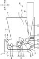
- FIG. 1 is a side sectional view showing an internal structure of an image forming apparatus 1 according to an embodiment of the present invention.
- a monochrome printer is exemplified as the image forming apparatus 1, but the image forming apparatus may be a copying machine, a facsimile apparatus, or a multifunction device having these functions, and an image forming apparatus for forming a color image. It may be.
- the image forming apparatus 1 includes a main body housing 10 having a substantially rectangular parallelepiped housing structure, a paper feeding unit 20, an image forming unit 30, and a fixing unit 40 housed in the main body housing 10.
- the front cover 11 is provided on the front side of the main body housing 10, and the rear cover 12 is provided on the rear side.
- the rear cover 12 is a cover that is opened during seat jam and maintenance.
- the upper surface of the main body housing 10 is provided with a paper ejection portion 13 from which the sheet after image formation is discharged.
- Various devices for performing image formation are installed in the internal space S defined by the front cover 11, the rear cover 12, and the paper ejection unit 13.
- the paper feed unit 20 includes a paper feed cassette 21 that houses a sheet to be image-formed. A part of the paper cassette 21 projects further forward from the front surface of the main body housing 10. The upper surface of the portion of the paper cassette 21 housed in the main body housing 10 is covered with the paper cassette top plate 21U.
- the paper cassette 21 is provided with a sheet storage space for accommodating the bundle of sheets, a lift plate for lifting the bundle of sheets for paper feeding, and the like.
- a sheet feeding portion 21A is provided on the upper portion of the paper feed cassette 21 on the rear end side. In the sheet feeding section 21A, a paper feeding roller 21B for feeding out the uppermost sheet of the sheet bundle in the paper feed cassette 21 one by one is arranged.
- the image forming unit 30 performs an image forming process for forming a toner image on the sheet sent out from the paper feeding unit 20.
- the image forming unit 30 includes a photoconductor drum 31, a charging device 32, an exposure device (not shown in FIG. 2), a developing device 33, and a transfer roller 34 arranged around the photoconductor drum 31. include.
- the photoconductor drum 31 includes a rotation axis and a cylindrical surface that rotates around the rotation axis. An electrostatic latent image is formed on the cylindrical surface, and a toner image corresponding to the electrostatic latent image is supported on the cylindrical surface. As the photoconductor drum 31, an OPC photoconductor drum can be used.
- the charging device 32 uniformly charges the surface of the photoconductor drum 31, is arranged at a predetermined interval with respect to the photoconductor drum 31, and discharges when a predetermined voltage is applied. Includes Scorotron.
- the exposure device has a laser light source and optical system devices such as a mirror and a lens, and irradiates the peripheral surface of the photoconductor drum 31 with light modulated based on image data given from an external device such as a personal computer. To form an electrostatic latent image.
- the developing device 33 supplies toner to the peripheral surface of the photoconductor drum 31 in order to develop the electrostatic latent image on the photoconductor drum 31 to form a toner image.
- the transfer roller 34 is a roller for transferring the toner image formed on the peripheral surface of the photoconductor drum 31 onto the sheet.
- the transfer roller 34 abuts on the cylindrical surface of the photoconductor drum 31 to form a transfer nip portion.
- the transfer roller 34 is given a transfer bias having the opposite polarity to that of the toner.
- the fixing unit 40 performs a fixing process for fixing the transferred toner image on the sheet.
- the fixing portion 40 includes a fixing roller 41 having a heating source inside, and a pressure roller 42 that is pressed against the fixing roller 41 to form a fixing nip portion between the fixing roller 41 and the fixing roller 41.
- the melt viscosity (Pa ⁇ s) of the non-magnetic one-component toner used in the developing device 33 at 95 ° C. is set in the range of 10,000 or more and 200,000 or less.
- the main body housing 10 is provided with a main transport path 22F and an inverted transport path 22B for transporting the sheet.
- the main transport path 22F is provided as a paper ejection port 14 facing the paper ejection portion 13 on the upper surface of the main body housing 10 from the sheet feeding portion 21A of the paper feeding unit 20 via the image forming portion 30 and the fixing portion 40.
- the reverse transfer path 22B is a transfer path for returning the single-sided printed sheet to the upstream side of the image forming unit 30 in the main transfer path 22F when double-sided printing is performed on the sheet.
- the main transport path 22F is extended so as to pass through the transfer nip portion formed by the photoconductor drum 31 and the transfer roller 34 from the lower side to the upper side. Further, a resist roller pair 23 is arranged on the upstream side of the main transport path 22F with respect to the transfer nip portion. The sheet is temporarily stopped by the resist roller pair 23, skew correction is performed, and then the sheet is sent out to the transfer nip portion at a predetermined timing for image transfer.
- a plurality of transport rollers for transporting sheets are arranged at appropriate positions on the main transport path 22F and the reverse transport path 22B. For example, a paper ejection roller pair 24 is arranged in the vicinity of the paper ejection port 14.
- the reversing transport path 22B is formed between the outer surface of the reversing unit 25 and the inner surface of the rear cover 12 of the main body housing 10.
- One roller of the transfer roller 34 and the resist roller pair 23 is mounted on the inner surface of the reversing unit 25.
- the rear cover 12 and the reversing unit 25 can each rotate around the axis of the fulcrum portion 121 provided at the lower end thereof.
- the rear cover 12 is opened.
- the reversing unit 25 is opened in addition to the rear cover 12.
- FIG. 2 is a cross-sectional view showing the structure around the photoconductor drum 31.
- the transfer roller 34 is arranged behind the photoconductor drum 31 so as to be in contact with the photoconductor drum 31, and the charging device 32 is arranged in front of and above the photoconductor drum 31 at predetermined intervals. It is arranged so as to face 31.
- a transfer nip portion is formed between the photoconductor drum 31 and the transfer roller 34, and the sheet passes through the transfer nip portion as shown by an arrow in FIG. At this time, the toner image is transferred from the photoconductor drum 31 to the sheet.
- the developing device 33 is arranged in front of and below the photoconductor drum 31 so as to face the photoconductor drum 31.
- the developing device 33 includes a developing housing 330, a developing roller 331, a supply roller 332, a stirring paddle 333, a regulating blade 334 (layer thickness regulating member), and a lower seal 335 (sealing member).
- the developing housing 330 houses a non-magnetic one-component toner inside.
- the developing housing 330 has a housing main body 330A and a housing lid portion 330B. As shown in FIG. 2, an opening for exposing a part of the developing roller 331 to the photoconductor drum 31 side is formed at the rear end portion of the developing housing 330.
- the developing roller 331 is rotatably supported by the developing housing 330 and has a peripheral surface for supporting toner.
- the developing roller 331 abuts on the photoconductor drum 31 and forms a developing nip portion for supplying toner to the photoconductor drum 31 together with the photoconductor drum 31.
- a cylindrical rubber layer (elastic body) is formed around the shaft of the SUS material or the SUM material.
- the rubber layer is made of NBR (Nitrile-Budiene Rubber) rubber as an example. Further, a predetermined coat layer may be formed on the surface of the rubber layer.
- the hardness of the surface of the developing roller 331 is set in the range of 50 or more and 80 or less in the Asker-C hardness.
- the supply roller 332 is arranged in front of and below the developing roller 331 so as to face the developing roller 331, and is rotatably supported by the developing housing 330.
- the supply roller 332 comes into contact with the developing roller 331 and forms a supply nip portion for supplying toner to the developing roller 331.
- the supply roller 332 is formed by fixing a cylindrical urethane sponge or a foam sponge (both elastic foams) around a predetermined metal shaft (shaft member).
- the hardness of the surface of the supply roller 332 is set in the range of 40 or more and 60 or less in terms of Asker-FP hardness.
- the supply nip width is set in a range of 0.2 mm or more and 1.5 mm or less in the rotational direction when viewed along the radial direction.
- the stirring paddle 333 is rotatably supported by the developing housing 330 in front of the supply roller 332. As shown in FIG. 2, the stirring paddle 333 includes an L-shaped shaft in a cross-sectional view and a PET film arranged so as to extend radially from the shaft.
- FIG. 2 shows the rotation directions of the developing roller 331, the supply roller 332, and the stirring paddle 333 when the image forming operation for the sheet is performed in the image forming apparatus 1.
- the developing roller 331 rotates so that its surface moves in the same direction as the surface of the photoconductor drum 31 at the developing nip portion.
- the peripheral speed ratio of the developing roller 331 to the photoconductor drum 31 is set to 1.55 times.
- the supply roller 332 rotates so that its surface moves in the direction opposite to the surface of the developing roller 331.
- the peripheral speed ratio of the developing roller 331 to the supply roller 332 is set to 1.55 times.
- the stirring paddle 333 rotates so as to supply the toner in the developing housing 330 to the supply roller 332 while scooping up the toner.
- the regulation blade 334 is in contact with the surface (peripheral surface) of the developing roller 331 on the downstream side in the rotation direction of the developing roller 331 from the supply nip portion and on the upstream side in the rotating direction of the developing roller 331 from the developing nip portion. ..
- the regulating blade 334 is fixed to the developing housing 330 so as to be inclined toward the upstream side in the rotational direction of the developing roller 331.
- the regulation blade 334 regulates the thickness (layer thickness) of the toner on the developing roller 331.
- the lower seal 335 is supported by the housing body 330A so as to close the gap between the developing roller 331 and the housing body 330A on the opposite side of the regulation blade 334.
- the tip of the lower seal 335 is in contact with the surface of the developing roller 331.
- the charging device 32 is arranged on the downstream side in the rotation direction of the photoconductor drum 31 when viewed from the transfer nip portion formed by the photoconductor drum 31 and the transfer roller 34. Therefore, a so-called cleanerless configuration is adopted, which is not provided with a known cleaning device. That is, when the toner image is transferred from the photoconductor drum 31 to the sheet at the transfer nip portion, the untransferred toner remains on the photoconductor drum 31. The untransferred toner passes through the charging device 32 and is recovered from the photoconductor drum 31 by the developing roller 331 of the developing device 33. At this time, when an image (toner image) is continuously formed on the sheet, the developing roller 331 collects the untransferred toner from the photoconductor drum 31, while the electrostatic latent image on the photoconductor drum 31. Supply toner to.
- the supply roller 332 supplies new toner to the developing roller 331 at the supply nip portion, and collects the toner not supplied from the developing roller 331 to the photoconductor drum 31 from the developing roller 331.
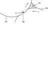
- FIG. 3 is an enlarged cross-sectional view of the facing portions of the developing roller 331 and the supply roller 332 of the developing device 33 according to the embodiment of the present invention.
- the shafts of the developing roller 331 and the supply roller 332 are supported by the developing housing 330, respectively, so that the surface of the developing roller 331 bites into the surface of the supply roller 332 by the amount H.
- a supply nip portion SN having a predetermined width is formed between the developing roller 331 and the supply roller 332 along the mutual rotation direction. Since the hardness of the supply roller 332 is lower than the hardness of the developing roller 331, the supply nip portion SN is formed mainly by deforming the surface of the supply roller 332 as shown in FIG.
- the toner conveyed by the supply roller 332 stays on the upstream side of the supply nip portion SN, and a toner pool TN is formed. Even when a high-density image is formed on the photoconductor drum 31 by the toner pool TN, the toner can be stably supplied from the supply roller 332 to the developing roller 331.
- the developing roller 331 and the supply roller 332 come into contact with each other by point contact in a cross-sectional view, the toner pool TN as shown in FIG. 3 is not sufficiently formed, so that the toner supply property may be significantly reduced. ..
- the hardness of the developing roller 331 is set in the range of 50 or more and 80 or less in the Asker-C hardness in order to come into contact with a hard member called the photoconductor drum 31. Therefore, in order for the developing roller 331 to be recessed into the supply roller 332 as shown in FIG. 3, it is desirable that the hardness of the supply roller 332 is set lower than the hardness of the developing roller 331.
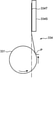
- FIG. 4 is a schematic cross-sectional view of the regulation blade 334 of the developing apparatus 33 according to the present embodiment.
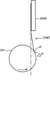
- FIG. 5 is a schematic cross-sectional view showing a state in which the regulation blade 334 of the developing apparatus 33 according to the present embodiment is in contact with the developing roller 331.
- FIG. 6 is a schematic cross-sectional view of the regulation blade 334Z of another developing device compared with the developing device 33 according to the present embodiment.
- FIG. 7 is a schematic cross-sectional view showing a state in which the regulation blade 334Z of another developing device compared with the developing device 33 according to the present embodiment is in contact with the developing roller 331.
- the regulating blade 334 when the regulating blade 334 is viewed from the axial direction of the developing roller 331 in a state where the regulating blade 334 is not in contact with the developing roller 331, the regulating blade 334 has a fixed end. It has a portion 334T (FIG. 5), a base end side straight line portion A, a tip end side straight line portion B, a first arc portion C, and a second arc portion D.
- the fixed end portion 334T is a portion of the regulation blade 334 that is fixed to the developing housing 330 and is supported by the support member 334S fixed to the developing housing 330.
- the support member 334S is composed of a plurality of members in FIG. 2, the support member 334S may be a single member.
- the base end side straight portion A is a portion of the regulation blade 334 that extends linearly from the fixed end portion 334T toward the peripheral surface of the developing roller 331 on the upstream side in the rotational direction of the developing roller 331.
- the tip side straight portion B is a portion of the regulation blade 334 that forms a free end of the regulation blade 334 on the side opposite to the fixed end portion 334T and extends linearly in a direction away from the peripheral surface of the developing roller 331. Is.
- the first arc portion C and the second arc portion D are a plurality of arc portions that are continuous with each other so as to connect the base end side straight line portion A and the tip end side straight line portion B.
- the radius of curvature of the plurality of arc portions is set smaller as it is closer to the tip side straight portion B. That is, the radius of curvature of the second arc portion D in FIG. 4 is smaller than the radius of curvature of the first arc portion C.
- the regulation blade 334 When the regulation blade 334 is supported by the support member 334S, as shown in FIG. 5, the first arc portion C and the second arc portion D of the regulation blade 334 come into contact with the peripheral surface of the developing roller 331, and the regulation nip portion P To form.
- the toner supplied from the supply roller 332 to the developing roller 331 is regulated by the regulating nip portion P, and is supplied to the developing nip portion where the photoconductor drum 31 and the developing roller 331 face each other.
- the radius of curvature of the plurality of arc portions (first arc portion C, second arc portion D) of the regulation blade 334 is set smaller as it is closer to the tip side straight portion B.
- the radius of curvature of the plurality of arc portions is set larger toward the downstream side in the rotation direction of the developing roller 331. Therefore, around the regulation nip portion P, the toner layer can be gradually regulated by each arc shape while the plurality of arc portions press the toner layer in a planar manner toward the peripheral surface of the developing roller 331. As a result, the toner easily enters the regulation nip portion P smoothly.
- the regulation blade 334 extends linearly from the fixed end portion 334T toward the peripheral surface of the development roller 331 on the upstream side in the rotation direction of the development roller 331, the regulation blade 334 extends.
- the developing roller 331 is arranged so as to extend toward the downstream side in the rotation direction, a large amount of toner is suppressed from entering the regulated nip portion P at one time, and the toner is prevented from entering the regulated nip portion P. Aggregation is suppressed.
- the toner smoothly enters the regulation nip portion P as described above, and the excess toner is removed. It is easy to flow away from the peripheral surface of the developing roller 331 along the shape of the arc portion on the upstream side and the straight portion B on the tip side, and it is suppressed that a large amount of toner stays on the upstream side of the regulation nip portion P.
- the toner supplied from the supply roller 332 to the developing roller 331 easily passes through the regulation nip portion P, and the toner is applied to the developing nip portion from the front edge of the solid image to the rear edge of the paper. It is possible to continue to supply stably. As a result, by stabilizing the supply of toner to the developing roller 331 while reducing the stress received by the toner when passing through the regulated nip portion P, the space between the front edge of the paper and the rear edge of the paper in the solid image is stabilized. It is possible to reduce the difference in image density.
- the plurality of arc portions (first arc portion C, first arc portion C, first 2 The arc portion D) forms a clothoid curve. That is, the slope of the tangent line of the first arc portion C and the slope of the tangent line of the second arc portion D are continuously set so as to include the boundary portion between the first arc portion C and the second arc portion D. The same applies to the boundary portion between the first arc portion C and the base end side straight line portion A, and the boundary portion between the second arc portion D and the tip end side straight line portion B.
- the toner flow may become unstable at the boundary between the adjacent arcs. While being suppressed, the stress of the toner around the regulation nip portion P is further reduced.
- the support member 334S supports the fixed end portion 334T of the regulation blade 334 so as to abut on the peripheral surface of the developing roller 331. That is, in the present embodiment, the region including the boundary portion between the first arc portion C and the second arc portion D is in contact with the peripheral surface of the developing roller 331 with a width.
- the plurality of arc portions can stably press the toner layer toward the peripheral surface of the developing roller 331 in a planar shape, the toner layer is pressed into each arc shape. Gradually regulated by means of more stable realization. As a result, it becomes easier for the toner to enter the regulation nip portion P more smoothly.
- the regulation blade 334 is a SUS301-CSP specified in JIS G4313 that has been subjected to tempering treatment of any of 3/4 ⁇ H, H and EH, or JIS G4313.
- the SUS304-CSP specified in the above is composed of one of 3/4 ⁇ H and H which has been subjected to a tempering treatment.
- the melt viscosity (Pa ⁇ s) of the non-magnetic one-component toner used in the developing device 33 at 95 ° C. is set in the range of 10,000 or more and 200,000 or less. In this case, it is possible to reduce the electric power input to the fixing unit 40 in order to fix the toner on the sheet.
- the regulated blade 334 has the above-mentioned shape and therefore passes through the regulated nip portion P. It is possible to stabilize the supply of toner to the developing roller 331 while reducing the stress received by the toner. Therefore, it is possible to reduce image defects such as density reduction and density unevenness when solid images are continuously printed.
- the non-magnetic toner is used to reduce the stress on the toner when passing through the regulated nip portion, and to improve the supply of toner to the developing roller.
- the non-magnetic toner is used to reduce the stress on the toner when passing through the regulated nip portion, and to improve the supply of toner to the developing roller.
- Table 1 shows the detailed conditions and experimental results of each Example and Comparative Example.
- a solid image is printed using the regulation blade 334Z shown in FIGS. 6 and 7, and in the embodiment, the solid image is printed using the regulation blade 334 according to the present embodiment shown in FIGS. 4 and 5. Is printed. In each case, the density difference between the density at the front and rear edges of the paper and the density of each density is measured.
- the developing apparatus 33 according to the embodiment of the present invention and the image forming apparatus 1 provided with the developing apparatus 33 have been described above. According to the present invention, by stabilizing the supply of toner to the developing roller while reducing the stress received by the toner when passing through the regulated nip portion, the space between the front edge of the paper and the rear edge of the paper in a solid image is achieved.
- a developing device capable of reducing the difference in image density of the above and an image forming device including the developing device are provided.
- the present invention is not limited to this, and for example, the following modified embodiments can be adopted.
- the image forming apparatus 1 is provided with one developing apparatus 33, but the image forming apparatus 1 is a color image forming apparatus having development apparatus 33 corresponding to a plurality of colors. It may be.
- the development housing 330 of the developing apparatus 33 has been described as storing the non-magnetic toner inside, but a toner container and a toner cartridge for storing the non-magnetic toner are provided separately from the developing housing 330. It may have.
- the regulation blade 334 has been described as having two arc portions (first arc portion C and second arc portion D), but the present invention is limited thereto. is not it.
- the regulation blade 334 may have three or more arcs, and it is desirable that these arcs form a clothoid curve.
Landscapes
- Physics & Mathematics (AREA)
- General Physics & Mathematics (AREA)
- Dry Development In Electrophotography (AREA)
Priority Applications (3)
| Application Number | Priority Date | Filing Date | Title |
|---|---|---|---|
| JP2022536347A JP7517424B2 (ja) | 2020-07-17 | 2021-07-12 | 現像装置およびこれを備えた画像形成装置 |
| CN202180060301.1A CN116134384A (zh) | 2020-07-17 | 2021-07-12 | 显影装置和具有该显影装置的图像形成装置 |
| US18/005,173 US20230266694A1 (en) | 2020-07-17 | 2021-07-12 | Developing device and image forming apparatus including the same |
Applications Claiming Priority (2)
| Application Number | Priority Date | Filing Date | Title |
|---|---|---|---|
| JP2020-123084 | 2020-07-17 | ||
| JP2020123084 | 2020-07-17 |
Publications (1)
| Publication Number | Publication Date |
|---|---|
| WO2022014534A1 true WO2022014534A1 (ja) | 2022-01-20 |
Family
ID=79554818
Family Applications (1)
| Application Number | Title | Priority Date | Filing Date |
|---|---|---|---|
| PCT/JP2021/026152 Ceased WO2022014534A1 (ja) | 2020-07-17 | 2021-07-12 | 現像装置およびこれを備えた画像形成装置 |
Country Status (4)
| Country | Link |
|---|---|
| US (1) | US20230266694A1 (enExample) |
| JP (1) | JP7517424B2 (enExample) |
| CN (1) | CN116134384A (enExample) |
| WO (1) | WO2022014534A1 (enExample) |
Citations (5)
| Publication number | Priority date | Publication date | Assignee | Title |
|---|---|---|---|---|
| JP2004246392A (ja) * | 2004-05-21 | 2004-09-02 | Fujitsu Ltd | 現像装置及び画像形成装置 |
| JP2007248490A (ja) * | 2006-03-13 | 2007-09-27 | Oki Data Corp | 画像形成ユニット及び画像形成装置 |
| JP2010033003A (ja) * | 2008-07-02 | 2010-02-12 | Ricoh Co Ltd | 現像装置、プロセスカートリッジおよび画像形成装置 |
| JP2010276948A (ja) * | 2009-05-29 | 2010-12-09 | Kyocera Mita Corp | 静電潜像現像用トナー及び静電潜像現像剤 |
| JP2014010215A (ja) * | 2012-06-28 | 2014-01-20 | Oki Data Corp | 画像形成ユニット及び画像形成装置 |
Family Cites Families (4)
| Publication number | Priority date | Publication date | Assignee | Title |
|---|---|---|---|---|
| JP2001060037A (ja) * | 1995-09-12 | 2001-03-06 | Brother Ind Ltd | 画像形成装置 |
| JP4256439B2 (ja) * | 2006-08-01 | 2009-04-22 | シャープ株式会社 | 凝集粒子の製造方法 |
| US9201336B2 (en) * | 2012-02-13 | 2015-12-01 | Ricoh Company, Ltd. | Developing device and image forming apparatus including a toner bearing member having a predetermined relationship with toner |
| US10036976B2 (en) * | 2015-12-17 | 2018-07-31 | Ricoh Company, Ltd. | Developing device, and image forming apparatus and process unit incorporating same |
-
2021
- 2021-07-12 US US18/005,173 patent/US20230266694A1/en not_active Abandoned
- 2021-07-12 JP JP2022536347A patent/JP7517424B2/ja active Active
- 2021-07-12 WO PCT/JP2021/026152 patent/WO2022014534A1/ja not_active Ceased
- 2021-07-12 CN CN202180060301.1A patent/CN116134384A/zh active Pending
Patent Citations (5)
| Publication number | Priority date | Publication date | Assignee | Title |
|---|---|---|---|---|
| JP2004246392A (ja) * | 2004-05-21 | 2004-09-02 | Fujitsu Ltd | 現像装置及び画像形成装置 |
| JP2007248490A (ja) * | 2006-03-13 | 2007-09-27 | Oki Data Corp | 画像形成ユニット及び画像形成装置 |
| JP2010033003A (ja) * | 2008-07-02 | 2010-02-12 | Ricoh Co Ltd | 現像装置、プロセスカートリッジおよび画像形成装置 |
| JP2010276948A (ja) * | 2009-05-29 | 2010-12-09 | Kyocera Mita Corp | 静電潜像現像用トナー及び静電潜像現像剤 |
| JP2014010215A (ja) * | 2012-06-28 | 2014-01-20 | Oki Data Corp | 画像形成ユニット及び画像形成装置 |
Also Published As
| Publication number | Publication date |
|---|---|
| US20230266694A1 (en) | 2023-08-24 |
| JP7517424B2 (ja) | 2024-07-17 |
| CN116134384A (zh) | 2023-05-16 |
| JPWO2022014534A1 (enExample) | 2022-01-20 |
Similar Documents
| Publication | Publication Date | Title |
|---|---|---|
| EP1826628A1 (en) | Image forming apparatus | |
| JP7512837B2 (ja) | 現像装置およびこれを備えた画像形成装置 | |
| JP2017211405A (ja) | 画像形成装置および制御方法 | |
| US9519241B2 (en) | Development device, process cartridge, and image forming apparatus | |
| JP7746043B2 (ja) | 規制部材、現像装置、プロセスカートリッジ、および、画像形成装置 | |
| JP7589484B2 (ja) | 画像形成装置 | |
| JP7517424B2 (ja) | 現像装置およびこれを備えた画像形成装置 | |
| US20170176886A1 (en) | Developing device, and image forming apparatus and process unit incorporating same | |
| JP7532976B2 (ja) | 現像装置およびこれを備えた画像形成装置 | |
| JP2021152628A (ja) | 現像装置およびこれを備えた画像形成装置 | |
| US11131944B2 (en) | Developing device regulates an amount of developer on a developing sleeve | |
| JP2022032389A (ja) | 現像装置およびこれを備えた画像形成装置 | |
| JP2019066663A (ja) | 現像装置、プロセスカートリッジおよび画像形成装置 | |
| JP2021152627A (ja) | 現像装置およびこれを備えた画像形成装置 | |
| US12124186B2 (en) | Image forming apparatus having controller to control potential bias applied between developing roller and supply roller according to cumulative drive time | |
| JP2005134734A (ja) | 現像装置および画像形成装置 | |
| JP4785554B2 (ja) | 現像装置,画像形成装置 | |
| JP4200020B2 (ja) | 画像形成装置 | |
| JP2021152629A (ja) | 現像装置およびこれを備えた画像形成装置 | |
| US11599038B2 (en) | Developing device and image forming apparatus provided therewith | |
| JP2011232527A (ja) | 現像装置 | |
| JP2022032390A (ja) | 現像装置およびこれを備えた画像形成装置 | |
| JPH10177297A (ja) | 現像装置 | |
| JP4654059B2 (ja) | 現像装置、プロセスカートリッジ及び画像形成装置 | |
| JP4726530B2 (ja) | 磁気シールを有する現像装置、および前記現像装置を備えた画像形成装置 |
Legal Events
| Date | Code | Title | Description |
|---|---|---|---|
| 121 | Ep: the epo has been informed by wipo that ep was designated in this application |
Ref document number: 21843011 Country of ref document: EP Kind code of ref document: A1 |
|
| ENP | Entry into the national phase |
Ref document number: 2022536347 Country of ref document: JP Kind code of ref document: A |
|
| NENP | Non-entry into the national phase |
Ref country code: DE |
|
| 122 | Ep: pct application non-entry in european phase |
Ref document number: 21843011 Country of ref document: EP Kind code of ref document: A1 |