WO2022014367A1 - Dispositif de communication et procédé de communication - Google Patents
Dispositif de communication et procédé de communication Download PDFInfo
- Publication number
- WO2022014367A1 WO2022014367A1 PCT/JP2021/025086 JP2021025086W WO2022014367A1 WO 2022014367 A1 WO2022014367 A1 WO 2022014367A1 JP 2021025086 W JP2021025086 W JP 2021025086W WO 2022014367 A1 WO2022014367 A1 WO 2022014367A1
- Authority
- WO
- WIPO (PCT)
- Prior art keywords
- data
- communication device
- transmission
- information
- control unit
- Prior art date
Links
- 238000004891 communication Methods 0.000 title claims abstract description 405
- 238000000034 method Methods 0.000 title claims abstract description 108
- 230000005540 biological transmission Effects 0.000 claims abstract description 423
- 239000000872 buffer Substances 0.000 claims description 95
- 230000000737 periodic effect Effects 0.000 claims description 2
- 238000005516 engineering process Methods 0.000 abstract description 49
- 238000012545 processing Methods 0.000 description 43
- 238000007726 management method Methods 0.000 description 27
- 101000741965 Homo sapiens Inactive tyrosine-protein kinase PRAG1 Proteins 0.000 description 9
- 102100038659 Inactive tyrosine-protein kinase PRAG1 Human genes 0.000 description 9
- 238000007405 data analysis Methods 0.000 description 7
- 238000012790 confirmation Methods 0.000 description 6
- 238000010276 construction Methods 0.000 description 5
- 238000004364 calculation method Methods 0.000 description 4
- 238000012937 correction Methods 0.000 description 4
- 230000003111 delayed effect Effects 0.000 description 4
- 230000000694 effects Effects 0.000 description 4
- 238000012986 modification Methods 0.000 description 3
- 230000004048 modification Effects 0.000 description 3
- 230000002093 peripheral effect Effects 0.000 description 3
- 239000004065 semiconductor Substances 0.000 description 3
- 241000209094 Oryza Species 0.000 description 2
- 235000007164 Oryza sativa Nutrition 0.000 description 2
- 238000010586 diagram Methods 0.000 description 2
- 238000000605 extraction Methods 0.000 description 2
- 239000000203 mixture Substances 0.000 description 2
- 235000009566 rice Nutrition 0.000 description 2
- 108700026140 MAC combination Proteins 0.000 description 1
- 238000004458 analytical method Methods 0.000 description 1
- 238000007796 conventional method Methods 0.000 description 1
- 230000001934 delay Effects 0.000 description 1
- 239000002360 explosive Substances 0.000 description 1
- 239000000284 extract Substances 0.000 description 1
- 239000004973 liquid crystal related substance Substances 0.000 description 1
- 239000013307 optical fiber Substances 0.000 description 1
- 230000001151 other effect Effects 0.000 description 1
Images


Classifications
-
- H—ELECTRICITY
- H04—ELECTRIC COMMUNICATION TECHNIQUE
- H04W—WIRELESS COMMUNICATION NETWORKS
- H04W74/00—Wireless channel access, e.g. scheduled or random access
- H04W74/08—Non-scheduled or contention based access, e.g. random access, ALOHA, CSMA [Carrier Sense Multiple Access]
- H04W74/0833—Non-scheduled or contention based access, e.g. random access, ALOHA, CSMA [Carrier Sense Multiple Access] using a random access procedure
-
- H—ELECTRICITY
- H04—ELECTRIC COMMUNICATION TECHNIQUE
- H04W—WIRELESS COMMUNICATION NETWORKS
- H04W74/00—Wireless channel access, e.g. scheduled or random access
- H04W74/08—Non-scheduled or contention based access, e.g. random access, ALOHA, CSMA [Carrier Sense Multiple Access]
- H04W74/0808—Non-scheduled or contention based access, e.g. random access, ALOHA, CSMA [Carrier Sense Multiple Access] using carrier sensing, e.g. as in CSMA
Definitions
- the present technology relates to a communication device and a communication method, and more particularly to a communication device and a communication method capable of preferentially transmitting data of a specific attribute.
- a network is constructed and operated between a plurality of communication devices, so that any communication device can transmit data after a predetermined random transmission waiting time has elapsed.
- An access control method that can be used was adopted.
- Patent Document 1 information on a new priority calculated by scheduling is added to the data again by the scheduling means, and information on the new priority given to the data stored in the transmission queue by the transmission control means.
- a configuration for setting the transmission waiting time based on the above is disclosed.
- attribute information is extracted from a plurality of packets received by a plurality of communication protocols, and a priority common to the plurality of communication protocols is determined for the plurality of packets based on the configuration of the extracted attribute information.
- a technique for processing a packet based on a determined priority is disclosed.
- This technology was made in view of such a situation, and makes it possible to more appropriately transmit data of a specific attribute with priority.
- the communication device of one aspect of the present technology estimates the transmission capacity for repeatedly transmitting a predetermined amount of information at a predetermined transmission interval, and transmits the data of a specific attribute with another communication device by random access control. It is a communication device including a control unit that controls to transmit data of the specific attribute by determining a predetermined transmission capacity to be transmitted according to an elapsed time of a predetermined transmission interval when an opportunity is acquired.
- the communication device estimates the transmission capacity for repeatedly transmitting the data of a specific attribute at a predetermined transmission interval with a predetermined amount of information, and is random with other communication devices. It is a communication method that controls the transmission of data of the specific attribute by determining a predetermined transmission capacity to be transmitted according to the elapsed time of a predetermined transmission interval when a transmission opportunity is acquired by access control.
- the transmission capacity for repeatedly transmitting a predetermined amount of information at a predetermined transmission interval is estimated, and other communication is performed.
- a transmission opportunity is acquired by the device and random access control, a predetermined transmission capacity to be transmitted is determined according to the elapsed time of a predetermined transmission interval, and data of the specific attribute is transmitted.
- the communication device of one aspect of the present technology sets the reception of data of a specific attribute by specifying the data transmission side communication device and the reception side communication device and exchanging communication parameters, and at predetermined transmission intervals.
- a communication device including a control unit that controls to periodically receive data of the specific attribute having a predetermined transmission capacity.
- the communication device sets the reception of data of a specific attribute by specifying the data transmission side communication device and the reception side communication device and exchanging communication parameters, and a predetermined value is provided. It is a communication method that controls periodical reception of data of the specific attribute having a predetermined transmission capacity for each transmission interval.
- the reception of data of a specific attribute is set and predetermined by specifying the data transmission side communication device and the reception side communication device and exchanging communication parameters.
- Data of the specific attribute having a predetermined transmission capacity is periodically received at each transmission interval of.
- the communication device on one side of the present technology may be an independent device or an internal block constituting one device.
- a network is constructed and operated between a plurality of communication devices, so that any communication device can transmit data after a predetermined random transmission waiting time has elapsed. The method was adopted.
- a method has been devised in which a wideband channel is secured in advance so that transmission on a communication channel does not cause congestion, and data is transmitted with a short transmission waiting time by using an arbitrary channel.
- frequency resources can be abundantly used, so by securing a communication channel for control in advance, a technology for setting a channel related to data transmission using this control channel is available. It was commonly used.
- the transmission path is connected to other wireless communication devices. It is required to use it fairly.
- the IEEE 802.11 standard document discloses a technology for setting the transmission waiting time based on the access category (AC: Access Category) of the data to be transmitted by EDCA (Enhanced Distributed Channel Access) control.
- AC Access Category
- EDCA Enhanced Distributed Channel Access
- next-generation technology of IEEE802.11 a technology that can store these data requiring low latency in a dedicated transmission buffer and transmit them with priority over other data is disclosed.
- the scheduling means again assigns information on the new priority calculated by scheduling to the data, and the transmission control means assigns the new priority to the data stored in the transmission queue.
- the technology for setting the transmission waiting time based on the information regarding the above is disclosed.
- attribute information is extracted from a plurality of packets received by a plurality of communication protocols, and a priority common to the plurality of communication protocols is given to the plurality of packets based on the configuration of the extracted attribute information.
- a technique for determining and processing a packet based on the determined priority is disclosed.
- Link Load is specified for each link, and for links with high Link Load (Link # 2), the latency is low.
- Link # 1 that transmit only data and have a low Link Load
- a technique for transmitting both low latency data and other data is disclosed.
- the order of priority for data transmission is determined by the access category of the data to be transmitted. Therefore, even data that requires a short latency by a real-time application is transmitted based on this mechanism. Control was in place.
- the transmission of the data is prioritized and there is a possibility that the desired latency request cannot be satisfied. rice field.
- the data is not stored in the transmission buffer, it will not be transmitted preferentially, and when the data used in the real-time application is received, it will be transmitted at the desired timing unless it is preferentially transmitted by the communication device on the transmitting side. There was a problem that I could not receive the data.
- the transmission waiting time is uniformly set in the data based on the information regarding the new priority set in the priority analysis processing unit, so that the priority is the highest.
- the data that was set high was transmitted first each time.
- Link Load is specified for each link, so only low latency data is transmitted for links with high Link Load (Link # 2), and other data is sent. The problem of not being able to send was left.
- a predetermined transmission capacity to be transmitted is determined according to the elapsed time of a predetermined transmission interval, and data of a real-time application or the like is determined. It proposes a configuration in which data of a specific attribute of is transmitted so that the above-mentioned problem can be solved.
- FIG. 1 shows an example of a configuration of a wireless communication network by a wireless communication system to which the present technology is applied.
- the configuration of a wireless LAN system is shown as an example of a wireless communication system.
- the communication device 10 constituting the wireless LAN system 1-1 is indicated by a white circle in the figure, and the communication terminal STA10-1 and the communication terminal STA10-2 are connected to the access point AP10.
- the solid lines A1 and A2 in the figure indicate that each of the communication devices 10 can communicate in this state.
- the access point AP20 and the communication terminal STA20 indicated by the shaded circles in the figure constitute another wireless LAN system 1-2, and each communication device 20 constitutes another wireless LAN system 1-2.
- the solid line arrow B1 in the figure indicates that communication is possible.
- the access point AP30 and the communication terminal STA30 indicated by the shaded circles in the figure further constitute another wireless LAN system 1-3, and their respective communications.
- the fact that the device 30 can communicate is indicated by the solid line arrow D1 in the figure.
- the access point AP10 exists at a position where it can receive signals from the access point AP20 and the communication terminal STA20, and the access point AP30 and the communication terminal STA30. Represents.
- the communication terminal STA10-1 exists at a position where signals from the access point AP20 and the access point AP30 can be received, and is represented by the broken line arrows C1 and E1 in the figure. Further, the communication terminal STA10-2 exists at a position where signals from the communication terminal STA20 and the communication terminal STA30 can be received, and is represented by the broken line arrows C4 and E4 in the figure.
- the access point AP10, the communication terminal STA10-1, and the communication terminal STA10-2 constituting the wireless LAN system 1-1 are combined with each other due to the existence of the wireless LAN system 1-2 and the wireless LAN system 1-3. It is necessary to carry out fair access to and from the communication equipment of.
- a communication device for transmitting data will be referred to as a transmitting side communication device
- a communication device for receiving data will be referred to as a receiving side communication device.
- the data transmitted from the transmitting side communication device 10Tx such as the access point AP10 is received by the receiving side communication device 10Rx such as the communication terminal STA10-1.
- FIG. 2 shows an example of frequency band and frequency channel allocation used in a wireless communication system to which the present technology is applied.
- 2.4GHz band when applied to an OFDM (Orthogonal Frequency Division Multiplexing) wireless signal with a 20MHz bandwidth of the IEEE802.11g standard, frequencies for at least two channels are set (the top row (first row) in the figure. ) "2.4GHz band").
- OFDM Orthogonal Frequency Division Multiplexing
- 5GHz band it is possible to secure multiple frequency channels applicable to OFDM wireless signals with a bandwidth of 20MHz for standards such as IEEE802.11a (1st and 2nd stages in the figure, "5GHz band A, B”. , C ").
- the operation in the 5 GHz band is subject to the conditions for determining the available frequency band, transmission power, and transmission possibility in the legal system of each country.
- Channel numbers such as 32, 36, 40, ... are attached to the first and second rows of Fig. 2, but in Japan, 8 channels of channels 36 to 64 and 11 of channels 100 to 140 are attached. It is possible to use the channel.
- channel 32, channel 68, channel 96, and channel 144 can be used, and in the frequency band above that, channels 149 to 173 can be used. ..
- 6GHz band A, B, C, D a usable frequency band
- 6GHz band A, B, C, D a usable frequency band
- -It is possible to arrange 12 channels in 8 bands.
- FIG. 3 shows a configuration in which frequency channels having a predetermined bandwidth are divided and used by combining freely available bands while avoiding the use of bands that are restricted in use.
- the bandwidth of 80 MHz is secured in 4 channels of the Unii-6 band of the 6 GHz band B to be the first link (Link # 1), and the Unii-8 band of the 6 GHz band D is used.
- An example is shown in which a bandwidth of 240 MHz is secured for 12 channels of the above and used as the second link (Link # 2), and links of these multiple bandwidths are combined to use a bandwidth of 320 MHz for a total of 16 channels.
- the wireless LAN system 1-1 when the wireless LAN system 1-1 performs communication using a plurality of links (multi-links) of the first link and the second link, the wireless LAN system 1-2 is the first.
- the links or when the wireless LAN system 1-3 is using the second link, fair access control must be separately implemented for each of these links.
- FIG. 4 shows a configuration using a transmit buffer for data requiring low latency by a real-time application.
- a transmission buffer 103 is configured for each access category in order to carry out predetermined EDCA control defined by the IEEE802.11 system.
- data is sequentially stored in the corresponding buffer according to the type of data, and transmission control is performed according to the priority of the data.
- AC_VO Voice
- AC_VI Video
- AC_BE Best effort
- AC_BG Background
- AC_VO represents a type corresponding to data such as voice data that requires low delay and bandwidth guarantee.
- AC_VI represents the type corresponding to data that requires bandwidth guarantee such as video data.
- AC_BE represents the type corresponding to normal data (best effort data).
- AC_BG represents a type corresponding to a large amount of data (background data) that is not restricted by time.
- audio data is stored in AC_VO buffer 103-2 corresponding to AC_VO
- video data is stored in AC_VI buffer 103-3 corresponding to AC_VI
- best effort data is stored in AC_BE. It is stored in the corresponding AC_BE buffer 103-4
- the background data is stored in the AC_BG buffer 103-5 corresponding to AC_BG.
- the priority order is AC_VO, AC_VI, AC_BE, AC_BG. ..
- low-latency data is stored in a dedicated buffer.
- low-latency data which is required to be transmitted with a short latency, is given an opportunity to be transmitted with priority over other data. Therefore, for example, the transmission waiting time is shorter than that of the conventional AC_VO voice data. It is configured to be able to send.
- an RTA buffer 103-1 for storing real-time application (RTA: RealTimeApplication) data (hereinafter, also referred to as RTA data) is added to the transmission buffer 103.
- RTA data is an example of low latency data.
- the communication device 10 is configured to take out data from each buffer and transmit the data based on the priority of the data when the transmission right is acquired by the transmission opportunity.
- FIG. 5 shows an example of transmission when the data of the real-time application is preferentially transmitted.
- FIG. 5 The upper part of FIG. 5 shows the data flow in the first link (Link # 1), and the lower part of FIG. 5 shows the data flow in the second link (Link # 2).
- the direction of time is the direction from the left side to the right side in the figure.
- RTA and AC_VO are ordered according to the priority of the data stored in the transmission buffer 103. , AC_VI, AC_BE, AC_BG, and then the data is transmitted in that order.
- BUSY a period during which transmission is not possible
- the RTA data from the RTA buffer 103-1 and AC_VO are sequentially transmitted.
- RTA data, audio data, and video data have passed after a predetermined short waiting time has elapsed. And, the best effort data and the background data are transmitted in order.
- FIG. 6 shows a modified example in which the data of the real-time application is preferentially transmitted.
- the first link (Link # 1) and the second link (Link # 2) are used in the above-mentioned multi-link configuration, but in the first link in the upper row, RTA data is used after a predetermined short waiting time has elapsed.
- RTA RTA
- audio data AC_VO
- video data AC_VI
- AC_BE best effort data
- the second link in the lower row is configured to transmit RTA data (RTA) at predetermined time intervals.
- RTA RTA data
- NAV Network Allocation Vector
- FIG. 7 shows a flow of processing for specifying the amount of data in a real-time application.
- the data of the real-time application (RTAData) is output from the application at an arbitrary reception interval (Interval) and arrives, and there is a high possibility that the timing has periodicity.
- RTA Data data of the real-time application
- Interval reception interval
- FIG. 7 the first arrival timing (RTA Output Timing # 1), the second arrival timing (RTA Output Timing # 2), and the third arrival timing (RTA Output Timing # 3) of the RTA data are shown. Is an arbitrary receipt interval (Interval).
- the data of the real-time application may be composed of data such as video data (RVideo), audio data (RAudio), and control information data (RControl), and all of these data or Some data is configured to arrive around the specified area.
- RVideo video data
- RAudio audio data
- RControl control information data
- FIG. 8 shows a flow of processing for estimating the transmit capacity (Capacity: Available Transmit Capacity).
- FIG. 8 when, for example, video data (RVideo), audio data (RAudio), and control information data (RControl) exist as RTA data arriving at each reception interval (Interval), A configuration is shown in which the amount of information obtained by adding a slight margin amount to those data is calculated as the transmission capacity (Capacity). That is, the receivable capacity can be calculated by adding a margin amount according to the transmission rate between communication devices to the amount of information per unit time of data such as video data.
- Capacity the transmission capacity
- FIG. 9 shows an example of a configuration for estimating the transmission capacity (Capacity) based on the used bandwidth.
- FIG. 9 shows a configuration in which the transmission capacity calculated in FIG. 8 described above is applied to the frequency bandwidth to be used to calculate the transmittable time in one transmission period.
- the upper row shows the configuration when multiple links (frequency bands) are used as multilinks, and the total transmission capacity of the bandwidths of all the links is calculated. For example, if the bandwidth is 320 MHz, the multilinks are calculated. The duration of the link's transmit capacity (Duration) is calculated.
- the middle stage shows the configuration when only the first link (frequency band) is used, and the transmission capacity obtained by adding the bands of the first link is calculated. For example, if the bandwidth of the first link is 240 MHz, the transmission capacity is calculated. The duration (Duration) of the transmission capacity of the first link is calculated.
- the lower row shows the configuration when only the second link (frequency band) is used, and the total transmission capacity of the second link band is calculated. For example, if the bandwidth of the second link is 80 MHz, the transmission capacity is calculated. The duration (Duration) of the transmission capacity of the second link is calculated.
- FIG. 10 shows an example of setting transmission parameters used for data transmission.
- the delay time required for input processing and access control are changed.
- the delay time is added each time, and the data is transmitted within the range of the transmission capacity duration (Duration) when the link of FIG. 9 described above is used.
- the receiving side communication device 10Rx since the receiving side communication device 10Rx requires time for output processing, these times are calculated and the actual data is actually recorded between the shortest state and the longest state of the transmission capacity duration. Is desired to be transmitted. Further, here, a series of processes on the transmitting side and the receiving side is considered as a configuration in which the series of processes arrives at regular transmission intervals (Interval).
- the access control delay shown in FIG. 10 is fixedly shown, but in reality, it is a time corresponding to the allowable delay time depending on the acquisition status of the transmission opportunity by the random access control. It can be seen that even if there is a delay up to, the effect is small.
- the transmission capacity (Capacity) is configured to be transmitted at the timing when one transmission opportunity is acquired.
- FIG. 11 shows an example of data transmission when an access control delay occurs.
- the transmitting side communication device 10Tx Transmit Device
- another communication device Other Device
- the receiving side communication device 10Rx Receive Device
- the transmission side communication device 10Tx has a predetermined transmission capacity (Capacity) with respect to the reception side communication device 10Rx.
- Data (“Data” in the figure) is performed.
- the transmission capacity (Capacity) of the next transmission interval (Interval) is added and transmitted together.
- a method of repeatedly transmitting data having a desired transmission capacity (Capacity) at a predetermined transmission interval (Interval) can be obtained without a lapse of time.
- the transmitting side communication device 10Tx transmits data of another communication device according to a predetermined access control procedure without causing an unnecessarily delayed delay in the data (RTA data, etc.) of a specific application such as a real-time application. It is configured to coexist and carry out.
- FIG. 12 shows an example of calculation when the transmission capacity (Capacity) is calculated by applying forward error correction (FEC) technology.
- FEC forward error correction
- FIG. 12 shows an example of applying forward error correction (FEC) technology to the data of a real-time application to calculate the transmission capacity at one time.
- FEC forward error correction
- TXOP Transmission Opportunity
- FIG. 13 shows an example of calculation when the transmission capacity is calculated by applying the ACK return and retransmission control technology according to the state of the transmission line.
- FIG. 13 shows an example of calculating the transmission capacity at one time by applying the ACK return after data transmission and the retransmission technology of undelivered data to the data of the real-time application.
- the transmitting side communication device 10Tx is configured to receive a receipt confirmation (ACK) from the receiving side communication device. Then, for example, if it is necessary to retransmit about half of the information of the video data (RVideo), the undelivered data is retransmitted.
- ACK receipt confirmation
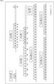
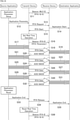
- FIG. 14 shows an example of a sequence of real-time application communication.
- FIG. 14 shows an example in which the transmitting side communication device 10Tx (Transmit Device) sets various transmission parameters when the application is started by the source application (SourceApplication).
- the process of setting the communication parameters of the real-time application is performed by the sender application on the sender side.
- the sender application when an application that delivers specific content is started, the communication parameters of the real-time application are acquired (ApplicationParameterSetup), and a series of real-time application communication request commands (ApplicationParameter) are sent side communication. It is sent to the device 10Tx (S12).
- a predetermined beacon signal is transmitted at a predetermined transmission timing (S11), but here, it indicates a state in which a real-time application is not set. It is configured to include information elements.
- the start command (ApplicationStart) is delivered to the destination application (DestinationApplication) (S14), and at the same time, the buffer capacity of the receiving side communication device 10Rx and the like.
- the processing capacity parameter is described in the start command (RTAStart) and returned (S15).
- the transmission interval (Interval) and transmission capacity (Capacity) described above are used as transmission parameters of the real-time application based on the information described in the start command (RTAStart). Is calculated, and a dedicated buffer space (for example, RTA buffer 103-1) is secured as needed (Set Real Time Operation).
- the predetermined transmission interval is determined by estimating the predetermined time interval from the time when the transmitting side communication device 10Tx receives the RTA data from the real-time application.
- the transmission capacity Capacity
- a predetermined transmission capacity is determined according to the available bandwidth at that time. do it.
- an information element indicating that these RTA parameters are set is constructed, and a beacon signal is transmitted at a predetermined transmission timing. It may be good (S16).
- These RTA parameters can be notified by transmitting a beacon signal including this information element to other communication devices existing in the vicinity.
- the transmission side communication device 10Tx stores the data in a dedicated buffer as needed, and has a predetermined transmission capacity at a predetermined transmission interval. It is transmitted as RTA data (RTA Data) of (S17, S18).
- the receiving side communication device 10Rx receives the transmitted RTA data (data for which an identifier is set), stores it in a dedicated buffer (for example, RTA receiving buffer 115-1), and stores these content data in the destination application. Is output (S19).
- the received data is RTA data
- it is stored in a dedicated buffer that preferentially outputs RTA data, and is output to the destination application according to the RTA data output format.
- the RTA data is output to the destination application before the maximum allowable delay time elapses.
- the receiving side communication device 10Rx outputs RTA data to the destination application and returns ACK information as needed (S20). If the RTA data cannot be decoded correctly, the NACK information requesting retransmission is returned.
- ACK information or NACK information is constructed based on the maximum allowable delay time.
- the transmitting side communication device 10Tx that has received the receipt confirmation (ACK / NACK) information, when the NACK information is returned, it may be retransmitted as necessary from the allowable delay time by the present technology, and the ACK information may be retransmitted. If, the transmission of RTA data at this transmission interval ends.
- the configuration is such that transmission of other communication devices and other data is performed until the next transmission interval arrives, and when the next transmission interval arrives, a series of these RTA data are transmitted. Is repeatedly carried out (S21 to S24, S25 to S28, S29 to S32).
- a real-time application opening command (ApplicationEnd) is sent to the transmitting communication device 10Tx in order to reset the RTA transmission. (S33).
- the transmitting side communication device 10Tx releases (cancels) the identifier that identifies the data (RTA data) of the real-time application, cancels the setting of the dedicated buffer space, and cancels the setting of the dedicated buffer space, and also releases the receiving side communication device 10Rx.
- a release command (RTA Release) is sent to (S34).
- the transmitting side communication device 10Tx operates as an access point, for example, in order to indicate that these RTA parameters have been released, the existing RTA information element settings are canceled and the transmission timing is determined. It may be configured to transmit a beacon signal (S36).
- the end command (ApplicationEnd) is delivered to the destination application (S35), and it is notified that the series of communication is completed.
- the release command RTA Release
- the identifier for identifying the RTA data may be released (released) and the setting of the dedicated buffer space may be released. No.
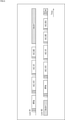
- FIG. 15 shows another example of a sequence of real-time application communication.
- FIG. 15 an example in which the transmitting side communication device 10Tx (Transmit Device) is specified and the transmitting side communication device 10Tx sets various transmission parameters when the application is started by the destination application (Destination Application). Shows.
- the process of setting the communication parameters of the real-time application is performed by the destination application on the receiving side.
- the communication parameters of the real-time application are acquired (ApplicationParameterSetup), and a series of real-time application request commands (ApplicationParameter) are sent to the receiving communication device. It is sent to 10Rx (ReceiveDevice) (S52).
- the transmitting side communication device 10Tx transmits a predetermined beacon signal at a predetermined transmission timing, for example, when operating as an access point (S51).
- the transmitting side communication device 10Tx In the receiving side communication device 10Rx that received this request command (ApplicationParameter) from the destination application, the transmitting side communication device 10Tx is specified, an identifier that identifies the data (RTA data) of the real-time application is set, and the receiving side communication is performed.
- a request command (RTARequest) including parameters of the buffer capacity and processing capacity of the device 10Rx is transmitted to the transmitting side communication device 10Tx (S53).
- a start command (ApplicationStart) is delivered to the sending application (S54), and the above-mentioned transmission interval and transmission are also used as transmission parameters of the real-time application.
- the capacity is calculated, and a dedicated buffer space (for example, RTA buffer 103-1) is secured as needed (Set Real Time Operation).
- the transmission side communication device 10Tx for example, when operating as an access point, an information element indicating that these RTA parameters are set is constructed, and a beacon signal is transmitted at a predetermined transmission timing. Good (S56). These RTA parameters can be notified by transmitting a beacon signal including this information element to other communication devices existing in the vicinity.
- the transmission side communication device 10Tx when content data arrives from the sender application at a predetermined cycle, the data is stored in a dedicated buffer as needed, and a predetermined transmission is performed at a predetermined transmission interval. It is configured to be transmitted as capacity RTA data (RTAData). Since the operation of RTA data transmission here is the same as that of FIG. 14 described above, details are omitted (S57 to S60, S61 to S64, S65 to S68, S69 to S72).
- a real-time application release command (ApplicationEnd) is sent to the receiving side communication device 10Rx in order to reset the RTA transmission (S73).
- the receiving side communication device 10Rx When the receiving side communication device 10Rx receives this notification, the identifier that identifies the data (RTA data) of the real-time application is released, and the release command (RTA Release) is transmitted to the transmitting side communication device 10Tx (S74). ).
- the transmitting side communication device 10Tx Upon receiving this release command (RTA Release), the transmitting side communication device 10Tx cancels the setting of the dedicated buffer space, and the end command (ApplicationEnd) is delivered to the sending application (S75), and a series of communication is performed. You will be notified that it has finished.
- the transmitting side communication device 10Tx operates as an access point, for example, in order to indicate that these RTA parameters have been released, the existing RTA information element settings are canceled and the transmission timing is determined. It may be configured to transmit a beacon signal (S76).
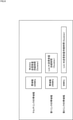
- FIG. 16 shows an example of the configuration of a communication device to which the present technology is applied.
- the communication device 10 shown in FIG. 16 is a wireless communication device configured as an access point AP10 or a communication terminal STA10 in the wireless LAN system 1-1 (FIG. 1), that is, a transmitting side communication device 10Tx or a receiving side communication device 10Rx. be.
- the communication device 10 includes a network connection module 11, an information input module 12, a device control module 13, an information output module 14, and a wireless communication module 15.
- the network connection module 11 is composed of, for example, a circuit having a function of connecting an optical fiber network or other communication line to an Internet network via a service provider as an access point AP10, peripheral circuits thereof, a microcontroller, a semiconductor memory, and the like. Will be done.
- the network connection module 11 performs various processes related to the Internet connection according to the control from the device control module 13.
- the network connection module 11 is configured to be equipped with a function such as a communication modem for connecting to the Internet network when the communication device 10 operates as an access point AP10.
- the information input module 12 is composed of input devices such as push buttons, a keyboard, and a touch panel, for example.
- the information input module 12 has a function of inputting instruction information corresponding to an instruction from the user to the device control module 13.
- the device control module 13 is composed of, for example, a microprocessor, a microcontroller, a semiconductor memory, or the like.
- the device control module 13 controls each part (module) in order to operate the communication device 10 as the access point AP10 or the communication terminal STA10.
- the device control module 13 performs various processes on the information supplied from the network connection module 11, the information input module 12, or the wireless communication module 15. Further, the device control module 13 supplies the information obtained as a result of its own processing to the network connection module 11, the information output module 14, or the wireless communication module 15.
- the device control module 13 supplies transmission data passed from an application in the upper layer of the protocol to the wireless communication module 15 when transmitting data, or receives data supplied from the wireless communication module 15 when receiving data. Is passed to applications in the upper layer of the protocol.
- the information output module 14 is composed of an output device including a display element such as a liquid crystal display, an organic EL display, and an LED (Light Emitting Diode) display, and a speaker that outputs voice or music.
- a display element such as a liquid crystal display, an organic EL display, and an LED (Light Emitting Diode) display
- a speaker that outputs voice or music.
- the information output module 14 has a function of displaying necessary information to the user based on the information supplied from the device control module 13.
- the information processed by the information output module 14 includes, for example, the operating state of the communication device 10 and information obtained via the Internet network.
- the wireless communication module 15 is composed of, for example, a wireless chip, a peripheral circuit, a microcontroller, a semiconductor memory, and the like.
- the wireless communication module 15 performs various processes related to wireless communication in accordance with the control from the device control module 13. Details of the configuration of the wireless communication module 15 will be described later with reference to FIG.
- a wireless communication module equipped with a wireless communication chip and peripheral circuits will be described as an example, but this technology is applied not only to the wireless communication module but also to, for example, a wireless communication chip and a wireless communication LSI. be able to. Further, in the wireless communication module, it is optional whether or not to include the antenna.
- the device control module 13 and the wireless communication module 15 are indispensable components, but the network connection module 11, the information input module 12, and the information output module 14 excluding them are configured. It is optional to include it in the element.
- each communication device 10 operating as an access point AP10 or a communication terminal STA10 can be configured to be composed of only required modules, and unnecessary parts are simplified or not incorporated. Can be.
- the network connection module 11 can be incorporated only in the access point AP10, and the information input module 12 and the information output module 14 can be incorporated only in the communication terminal STA10.
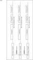
- FIG. 17 shows an example of the configuration of the wireless communication module 15 of FIG.
- the wireless communication module 15 is connected to another module, has an interface 101 for exchanging various information and data, an RTA data determination unit 102 for determining the attributes of transmission data from access categories, and temporary transmission data for each category. It is configured to include a transmission buffer 103 to be stored in.
- the transmission buffer 103 stores the RTA buffer 103-1 for storing RTA data for real-time applications, the AC_VO buffer 103-2 for storing audio data, the AC_VI buffer 103-3 for storing video data, and the best effort data.
- AC_BE buffer 103-4 and AC_BG buffer 103-5 for storing background data.
- the RTA operation management unit 104 that controls the transmission / reception operation for real-time applications, which is a characteristic configuration of the present technology
- the transmission control unit 105 that dequeues the order of transmission data
- the timing control that controls the transmission timing.
- a transmission frame construction unit 107 that constructs a data frame to be transmitted, an access control unit 108 that controls transmission and reception of data, and a transmission processing unit 109-1, 109- that performs a transmission operation at each link. 2 is included.
- the transmission processing unit 109-1 performs a transmission operation related to the first link (Link # 1).
- the transmission processing unit 109-2 performs a transmission operation related to the second link (Link # 2).
- an antenna control unit 110 is provided that controls transmission of a transmission signal from the antenna group 111 to another communication device 10 and reception of a transmission signal transmitted from the other communication device 10 via the antenna group 111. ..
- the antenna control unit 110 and the antenna group 111 may not be included in the wireless communication module 15.
- the wireless communication module 15 is configured to include reception processing units 112-1 and 112-2 at each link, which perform a reception operation using the received signal received by the antenna as a predetermined signal.
- the reception processing unit 111-1 performs a reception operation related to the first link (Link # 1).
- the reception processing unit 111-2 performs a reception operation related to the second link (Link # 2).
- It also includes a receive frame extraction unit 113 that extracts a predetermined data frame from the received signal, a data analysis unit 114 that analyzes the data included in the received data frame, and a receive buffer 115 that temporarily stores the received data. It is composed.
- the receive buffer 115 is a group of buffers composed of a receive buffer 115-2 for storing data excluding RTA data and an RTA receive buffer 115-1 as a dedicated buffer space for storing RTA data for real-time applications.
- an output data construction unit 116 that is constructed as data in the output format for delivery to a predetermined application, and finally passes data to an application of a connected device or the like via an interface 101. It has become.
- the RTA operation management unit 104 has an interface 101, a transmission control unit 105, and a timing control unit 106 in order to realize a function related to control of transmission of RTA data for a real-time application as a characteristic function of the present technology. , And in cooperation with each of the receive buffer 115.
- the access control unit 108 has a timing control unit 106, a transmission frame construction unit 107, and a transmission processing unit 109-in order to realize a function related to data transmission and reception control as a characteristic function of the present technology. It operates in cooperation with 1,109-2, the antenna control unit 110, and the reception processing units 112-1 and 112-2, respectively.
- the RTA operation management unit 104 and the access control unit 108 control the operation of each unit to perform, for example, the following processing.
- the wireless communication module 15 of the communication device 10 transmitter communication device 10Tx
- data of a specific attribute for example, RTA data
- a predetermined transmission interval (Interval) by the RTA operation management unit 104, the access control unit 108, or the like.
- the transmission capacity (Capacity) for repeatedly transmitting a predetermined amount of information is estimated, and when a transmission opportunity is acquired by random access control with another communication device (reception side communication device 10Rx), a predetermined transmission interval is obtained.
- Control is performed to determine a predetermined transmission capacity (Capacity) to be transmitted according to the elapsed time of (Interval) and transmit data of a specific attribute (for example, RTA data).
- the data transmission side communication device (sending side communication device 10Tx) and the reception side communication device are used by the RTA operation management unit 104, the access control unit 108, and the like.
- reception side communication device 10Rx and exchanging communication parameters, reception of data with specific attributes (for example, RTA data) is set, and a predetermined transmission capacity (division) is set for each predetermined transmission interval (Interval). Control is performed to periodically receive data of a specific attribute (for example, RTA data) that becomes Capacity).
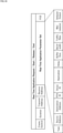
- FIG. 18 shows an example of the configuration of commands related to the setup of a real-time application.
- the configuration example shown in FIG. 18 shows a configuration according to the frame format used in the wireless LAN system, but the configuration is limited to this configuration. It does not have to be.
- This frame is configured to include Frame Control indicating the type of the frame, Duration indicating the duration, Transmit Address indicating the address of the transmitting side, and Receive Address indicating the address of the receiving side as predetermined header information. Furthermore, this frame contains a real-time application parameter set (RealTimeApplicationParameterSet), which is necessary for implementing control to which this technology is applied, and has a frame check sequence (FCS: Frame Check Sequence) at the end. It is added and configured.
- RealTimeApplicationParameterSet Real-time application parameter set
- FCS Frame Check Sequence
- This real-time application parameter set includes Type indicating the command format, Source Address indicating the source address of the sender, Destination Address indicating the destination address of the destination, RTA ID indicating the identifier of RTA, Group ID indicating the group, and application.
- Application indicating the type of, Delay indicating the allowable delay time, Buffer Size indicating the buffer size, Band-Width indicating the bandwidth information to be used, Traffic Rate indicating the transmission rate expected for traffic, Max indicating the maximum delay time. It consists of information such as Latency and Delayed Output, which indicates the data output when a delay occurs.
- the necessary parts are described and transmitted from the transmitting side, and the information is used by the receiving side.
- the example of the configuration of the real-time application parameter set shown in FIG. 18 is only an example, for example, information on the maximum allowable delay of data, information on the buffer capacity, information on the bandwidth used, and information on the bandwidth used as shown in FIG. If information such as information regarding the data output format is included as a parameter, other parameters (for example, parameters corresponding to the information shown in FIG. 19) may be included.
- FIG. 19 shows an example of the configuration of application parameters.
- the parameters of this application are the parameters exchanged between the application device and the communication device 10.
- An application device is a device equipped with a specific application such as a real-time application.
- FIG. 19 a configuration according to the frame format used in the wireless LAN system is shown, and as predetermined header information, Frame Control indicating the type of frame, Duration indicating the duration, and the address on the transmitting side are shown.
- the Transmit Address and Receive Address indicating the address of the receiving side are described, but they may be added or deleted as necessary.
- the parameters actually exchanged are described as an application parameter set (ApplicationParameterInformation), and FCS is further added.
- This parameter is the Type that indicates the notification of the application parameter (ApplicationParameter), the start of the application (ApplicationStart), or the end of the application (ApplicationEnd), the SourceAddress that indicates the address of the sender, and the destination side.
- the destination address which indicates the address of, is configured so that the parameters corresponding to each application are described.
- the parameters corresponding to this application are, for example, Application Type indicating the application format in the case of moving image information, Frame Size indicating the frame size of the data, Frame Rate indicating the frame rate, Max Latency indicating the maximum delay time, and buffer. It consists of BufferSize, which indicates the size, OutputType, which indicates the format for outputting data, OutputDelay, which indicates the output delay time, and RTAAttribute, which indicates the attributes of the real-time application.
- the transmission interval (Interval) and the transmission capacity (Capacity) regarding the RTA data transmitted by wireless communication are calculated with reference to these parameters. It has become.
- the maximum allowable delay time is calculated from information such as Application Type indicating the application format, Output Type indicating the data output format, and Output Delay indicating the output delay time, and the maximum allowable delay time is calculated in FIG.
- the configuration that determines the transmission interval (Interval) and transmission capacity (Capacity) from information such as Frame Size indicating the frame size and Frame Rate indicating the frame rate taking into account the indicated input processing delay time and output processing delay time. It has become.
- parameters may be estimated using other parameters or the like.
- parameters may be included as parameters according to the application.
- information such as information on the maximum allowable delay of data, information on the buffer capacity, and information on the output format of the data as shown in FIG. 19 is included as parameters, other parameters may be used. Parameters may be included.
- FIG. 20 shows an example of the configuration of an information element that notifies the settings of a real-time application.
- This information element is included in, for example, a beacon frame, etc., and is notified to transmit data related to a real-time application to other communication devices in the vicinity, and the transmission interval, transmission capacity, duration, and the like. Parameters can be notified.
- This information element is as follows: Element ID indicating the element identifier, Length indicating the information length, Type indicating the format, Maximum Latency indicating the maximum allowable delay time, Average Latency indicating the average delay time, and Available indicating the available channels. Various parameters such as Channel, Transmit Capacity indicating transmission capacity, Transmit Interval indicating transmission interval, and Maximum Duration indicating maximum duration are described.
- FIG. 21 shows an example of a frame configuration of real-time application data.
- an identifier or a flag for identifying real-time application data is stored in the header part of the data, so that a buffer (for example, RTA reception) for which priority processing is performed by the receiving side communication device 10Rx is performed. It is used to facilitate the storage of data in the buffer 115-1).
- a configuration is shown in which a flag for identifying RTA ID or RTA data is prepared in the SIG-A field of the PLCP (Physical Layer Convergence Protocol) header.
- DM Physical Layer Convergence Protocol
- the free bit of the delimiter (DM: Delimiter) added before the MPDU (MAC Protocol Data Unit) constituting the PPDU (PLCP Protocol Data Unit) is used, and the data of the MPDU is used. It may be possible to set a flag (ASAP) indicating that the data is processed promptly.
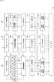
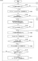
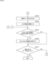
- step S101 the RTA operation management unit 104 determines whether the application that executes RTA communication is started and activates RTA communication, and if it is determined that the application that executes RTA communication is started (S101). "YES"), the process proceeds to step S102.
- step S102 the RTA operation management unit 104 acquires the parameters of the started application (for example, the parameters shown in FIG. 19).
- step S103 the RTA operation management unit 104 determines whether the own device is the transmitting side communication device 10Tx, and if the own device is determined to be the transmitting side communication device 10Tx (“YES” in S103), processing. Is advanced to step S104.
- step S104 the RTA operation management unit 104 identifies the receiving side communication device 10Rx and transmits an RTA Request command.
- step S105 when the RTA operation management unit 104 determines whether the RTA Start command has been received from the receiving side communication device 10Rx and determines that the RTA Start command has been received (“YES” in S105), the process is The process proceeds to step S106, and the processing of steps S106 and S107 is executed by the RTA operation management unit 104.
- the transmitting side communication device 10Tx (“YES” in S103) and receiving the RTA Start command (for example, the parameter information included in the command shown in FIG. 18) from the receiving side communication device 10Rx.
- the operating time of the real-time application is calculated (S106), and the parameters of these RTAs are set (S107). If the RTA Start command has not been received until a predetermined time (“NO” in S105), the parameters may be reset and the RTA Request command may be retransmitted.
- step S108 the RTA operation management unit 104 determines whether or not the RTA data transmission side communication device 10Tx is used, and if it is determined that the RTA data transmission side communication device 10Tx is used (“YES” in S108), processing is performed. Is advanced to step S109.
- step S109 the RTA operation management unit 104 sets the RTA ID identifier and the dedicated transmission buffer 103 (RTA buffer 103-1) as necessary.
- step S110 the RTA operation management unit 104 determines whether or not the own device is operating as an access point, and if it is determined that the own device is operating as an access point (“YES” in S110), the process is performed. , Step S111.
- step S111 the RTA operation management unit 104 sets the RTA IE in which these parameters are described, adds the RTA IE to the beacon frame, and transmits the RTA IE.
- step S111 If the process of step S111 is completed or the determination process of step S110 determines that the access point is not operating, the process returns to step S101, and the subsequent processes are repeated.
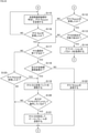
- step S101 determines whether RTA communication has been activated. If it is determined in the determination process of step S101 that RTA communication has not been activated, the process proceeds to step S112 of FIG.
- step S112 when the RTA operation management unit 104 determines whether the RTA Request command has been received from the receiving side communication device 10Rx and determines that the RTA Request command has been received (“YES” in S112), the process is The process proceeds to step S113, and the processing of steps S113 and S114 is executed by the RTA operation management unit 104.
- the transmitting side communication device 10Tx receives the RTA Request command from the receiving side communication device 10Rx (“YES” in S112), the request is made. If the RTA can be set with reference to the parameters (“YES” in S113), the parameters of the corresponding application (eg, the parameters shown in FIG. 19) are acquired (S114). Then, the process proceeds to step S106 of FIG. 22 described above, and the RTA parameters are set.
- step S103 If it is determined in the determination process of step S103 that the own device is the receiving side communication device 10Rx (“NO” in S103), the process proceeds to step S115 of FIG.
- step S115 the RTA operation management unit 104 identifies the transmitting side communication device 10Tx and transmits an RTA Request command.
- step S116 the RTA operation management unit 104 determines whether or not the RTA Start command has been received from the transmitting side communication device 10Tx, and if it is determined that the RTA Start command has been received (“YES” in S116), The process proceeds to step S117, and the process after step S117 is executed by the RTA operation management unit 104. If it is determined that the RTA Start command has not been received until a predetermined time (“NO” in S116), the parameter may be reset and the RTA Request command may be retransmitted.
- step S112 when it is determined in the determination process of step S112 that the RTA Request command has not been received (“NO” in S112), or when it is determined in the determination process of step S113 that the RTA cannot be set. (“NO” in S113), the process proceeds to step S117.
- RTA buffer 103-1 The set RTA ID identifier and the dedicated transmission buffer 103 (RTA buffer 103-1) are released as necessary (S119). If the own device is operating as an access point (“YES” in S120), RTAIE is set to describe that these parameters have been released, and is added to the beacon frame for transmission (“YES”). S121).
- the RTA Release command is transmitted to the transmitting side communication device 10Tx (S122). Further, when it is determined in the determination process of step S117 that the RTA communication is not terminated (“NO” in S117) and the RTA Release command is received (“YES” in S123), the communication on the receiving side is performed. Since the RTA Release command has been received from the device 10Rx, the process proceeds to step S119, and the RTA communication parameter is released.
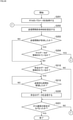
- step S201 the RTA operation management unit 104 acquires the transmission parameter of the real-time application, and sets the arrival time of the timing corresponding to the interval according to the transmission interval set as the acquired transmission parameter (S202).
- step S203 the RTA operation management unit 104 determines whether or not the set transmission interval has arrived, and if it is determined that the transmission interval has arrived (“YES” in S203), the process proceeds to step S204.
- step S204 the transmission control unit 105 determines whether the RTA data is stored in the predetermined transmission buffer 103 (RTA buffer 103-1), and if it is determined that the RTA data is stored (“S204”, “ YES ”), the process proceeds to step S205 of FIG.
- step S205 the access control unit 108 determines whether or not the wireless transmission line can be used, and the processes of steps S206 to S213 are executed according to the determination result.
- the transmission capacity duration of the entire band is acquired (S207).
- the transmission capacity duration of the part of the band is acquired (S209), and the transmission of another link is awaited. Time is acquired (S210), and based on the acquired information, the transmission capacity with only available links is calculated (S211).
- step S213 the process proceeds to step S214.
- step S215 the RTA operation management unit 104 determines whether or not the transmission of the transmission capacity is completed within the allowable transmission time based on the elapsed time in the acquired current transmission interval, and the transmission control is performed according to the determination result.
- the processing of steps S215 to S217 is executed by the unit 105, the access control unit 108, and the like.
- step S217 If it is determined that the process of step S217 is completed or that the data to be transmitted does not exist in the determination process of step S215 (“NO” in S215), the process returns to step S202 of FIG. 24. , Subsequent processing is repeated.
- step S203 determines whether the transmission control unit 105 determines whether the conventional access category data (voice data or the like), that is, predetermined data is stored in the transmission buffer 103, and the transmission control is performed according to the determination result.
- the processing of steps S219 to S221 is executed by the unit 105, the access control unit 108, and the like.
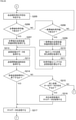
- step S301 the data analysis unit 114 acquires the received data obtained by the control of the access control unit 108 or the like, determines whether the acquired received data is the data addressed to itself (S302), and the self-addressed data. Performs determination processing (S303) as to whether the received data is RTA data.
- steps S302 and S303 if the received data is data addressed to itself (“YES” in S302) and is RTA data (“YES” in S303), the process is performed in step S304.
- the process is advanced, and the processes of steps S304 to S312 are executed by the RTA operation management unit 104, the data analysis unit 114, the access control unit 108, and the like.
- the parameters of the set real-time application are referenced (S304) and the data arrives within the allowable delay time (“YES” in S305), the receipt confirmation (ACK / NACK) information is displayed. It is constructed (S306). Then, when all the data of the transmission capacity at one time can be collected (“YES” in S307), the RTA data is output to the application after the output time of the data has arrived (“YES” in S308). (S309).
- delayed ACK information is constructed. (S311), and RTA data is output to the application (S309).
- the delayed NACK information is constructed and the RTA data is discarded without being output.
- step S313 the data analysis unit 114 determines whether or not the receipt confirmation (ACK / NACK) information needs to be returned, and when it is determined that the receipt confirmation (ACK / NACK) information needs to be returned (S313). "YES"), the process proceeds to step S314.
- step S314 the access control unit 108 or the like transmits the receipt confirmation (ACK / NACK) information.
- step S303 of FIG. 26 determines whether the data is RTA data in the determination process of step S303 of FIG. 26 is, for example, it is determined to be normal data (“NO” in S303).
- the process proceeds to step S315 of FIG. 27.
- RTA operation management unit 104, data analysis unit 114, access control unit 108, and the like execute the processes of steps S315 and S316.
- step S317 the data analysis unit 114 determines whether or not there is data to be retransmitted, and if there is no data to be retransmitted (“YES” in S317), a series of reception processes is terminated. If there is data to be retransmitted (“NO” in S317), the process returns to step S301 in FIG. 26, and the data reception process is continued.
- the transmitting side communication device 10Tx can be configured as, for example, an access point AP10 (base station), and the receiving side communication device 10Rx can be configured, for example, as a communication terminal STA10 (terminal station).
- the transmitting side communication device 10Tx or the receiving side communication device 10Rx is configured to be configured as a part (for example, a wireless communication module, a wireless chip, etc.) of the devices (parts) constituting the access point AP10 or the communication terminal STA10. May be good.
- the receiving side communication device 10Rx configured as the communication terminal STA10 may be a wireless device such as a smartphone, a tablet terminal, a game device, a mobile phone, a personal computer, a digital camera, a television receiver, a wearable terminal, or a speaker device. It can be configured as an electronic device having a communication function.
- the communication terminal STA10 supports only the reception of data such as a device such as a controller that transmits command data according to a user's operation and a display device that receives and displays video data. It may be a device.
- a wireless communication method in which a random access control delay occurs like a wireless LAN system so that the content specified by a user operating in a specific application such as a real-time application can be output with a short delay time. Also, in order to suppress the influence of delay as much as possible, we propose a priority transmission control method that can transmit a certain amount of information in a predetermined cycle.
- a wireless communication device and a wireless communication method that preferentially transmit data so that transmission opportunities can be obtained periodically. That is, in order to suppress the influence of delay as much as possible, we are proposing a wireless communication device and a wireless communication method in which a fixed amount of data is preferentially transmitted in a predetermined cycle.
- the data to be preferentially transmitted may be content data specified in advance by the user, may be data of a specific application, may be a predetermined data type, and may be within a specific time. It may be data directed from a specific communication device to a specific communication device, or it may be data for a group of these communication devices, and an identifier (flag) indicating that any of these data groups are output with a short delay time. ) Is set, and access control is implemented so that transmission opportunities are preferentially obtained at predetermined cycles.
- the frequency of priority transmission is controlled, and in order to avoid unnecessary transmission, the capacity of one transmission and the interval of priority transmission It is configured to set the transmission interval. If the data is transmitted within the transmission interval, the data is not transmitted until the next transmission interval arrives, but the data is used for transmission of another communication device, and the transmission path is used more than necessary. It is configured not to occupy.
- a predetermined transmission interval is determined in advance and data transmission is performed within the transmission interval, data transmission is not performed until the next transmission interval arrives, and the data is transmitted to another communication device. It is a communication control method that does not occupy the transmission line more than necessary.
- the maximum delay time information that allows the output of the content of a specific application the information of the reception cycle in which the data information of the content is delivered, and the communication on the receiving side. From the buffer capacity information of the device, the delay status of the access control of the transmission line, etc., the amount of one transmission information is set as the transmission capacity, calculated according to the bandwidth information of the link, and this is transmitted within the allowable delay time.
- the receiving status of the data to be transmitted is monitored by the transmitting communication device, and when the data addressed to a specific communication device is periodically transmitted, the above maximum It may be configured to estimate the allowable delay time.
- the data in which these identifiers are described may be stored in a dedicated transmission buffer, and by performing control for preferentially transmitting from the transmitting side communication device to the receiving side communication device based on the transmission parameter.
- the configuration may be such that the real-time communication desired by a specific application is realized.
- the transmission opportunity is prioritized in a predetermined cycle.
- the effect of delay due to access control can be suppressed as much as possible.
- a predetermined transmission interval is determined in advance and data transmission is performed within that transmission interval, data transmission is not performed until the next transmission interval arrives, and the data is transmitted to another communication device.
- data it is possible to obtain a method of using the transmission line fairly with other data without occupying the transmission line more than necessary.
- the allowable delay time is determined and data transmission cannot be started by the allowable delay time, access is performed by temporarily increasing the transmission capacity together with the data to be transmitted at the next transmission interval. Control delay can be suppressed.
- identifiers For data to be sent preferentially, content data specified in advance by the user, data of a specific application, content data defined by a predetermined attribute, within a specific time Any data group can be output with a short delay time according to the needs of the user, such as data directed from a specific communication device to a specific communication device, data for a group of these communication devices, and the like.
- the data can be distinguished from other data, and the transmission side communication device can be transferred to the reception side communication device based on a predetermined transmission parameter. It is possible to implement control for preferential transmission.
- the processes performed by the computer according to the program do not necessarily have to be performed in chronological order in the order described as the flowchart. That is, the processing performed by the computer according to the program includes processing executed in parallel or individually (for example, processing by parallel processing or processing by an object).
- the program may be processed by one computer (processor) or may be distributed processed by a plurality of computers.
- the program may be transferred to a distant computer for execution.
- system means a set of a plurality of components (devices, modules (parts), etc.), and it does not matter whether all the components are in the same housing.
- each step described in the above flowchart can be executed by one device or can be shared and executed by a plurality of devices. Further, when a plurality of processes are included in one step, the plurality of processes included in the one step can be executed by one device or shared by a plurality of devices.
- (1) Estimate the transmission capacity for repeatedly transmitting the data of a specific attribute at a predetermined transmission interval with a predetermined amount of information.
- a predetermined transmission capacity to be transmitted is determined according to the elapsed time of a predetermined transmission interval, and data of the specific attribute is controlled to be transmitted.
- a communication device equipped with a control unit. (2) The communication device according to (1) above, wherein the control unit stops the transmission of data having the specific attribute until a predetermined transmission interval arrives after transmission of data having a predetermined transmission capacity.
- the control unit adds the transmission capacity to be transmitted at the next transmission interval.
- the control unit sets a predetermined transmission interval and a predetermined transmission capacity by specifying a data transmission side communication device and a reception side communication device and exchanging communication parameters. Communication device described in Crab.
- the control unit transmits a request for the communication parameter including information on the maximum allowable delay of the data, information on the buffer capacity, information on the bandwidth used, and information on the output format of the data to the data receiving side communication device.
- the communication device according to (4).
- the control unit Set an identifier to identify data of a specific attribute, The communication device according to any one of (1) to (5), wherein the set identifier is added to the data of the specific attribute transmitted at a predetermined transmission interval.
- It also has a buffer to store data for specific attributes specified by the user.
- the communication device according to any one of (1) to (6), wherein the control unit transmits data of the specific attribute stored in the buffer when the transmission opportunity is acquired.
- the control unit determines a predetermined transmission interval by estimating a predetermined time interval from the time when the data transmitting side communication device receives data of a specific attribute from the application.
- the control unit estimates a predetermined amount of information that can be transmitted at a predetermined transmission interval based on information on the maximum allowable delay of data, information on the buffer capacity of the receiving side communication device, and information on the bandwidth used.
- the communication device according to any one of (1) to (8) above, which determines a predetermined transmission capacity.
- the communication device determines a predetermined transmission capacity.
- the control unit determines a predetermined transmission capacity according to the available bandwidth at that time.
- (11) The communication device according to (6) above, wherein the control unit cancels the setting of the identifier when the transmission of the data of the specific attribute is completed.
- the communication device Estimate the transmission capacity for repeatedly transmitting the data of a specific attribute at a predetermined transmission interval with a predetermined amount of information. Communication that controls the transmission of data of the specific attribute by determining a predetermined transmission capacity to be transmitted according to the elapsed time of a predetermined transmission interval when a transmission opportunity is acquired by random access control with another communication device. Method. (13) By specifying the data transmitting side communication device and the receiving side communication device and exchanging communication parameters, it is possible to set the reception of data with a specific attribute.
- a communication device including a control unit that controls to periodically receive data of the specific attribute having a predetermined transmission capacity at a predetermined transmission interval.
- control unit transmits a notification of the communication parameter including information on the maximum allowable delay of data, information on the buffer capacity, information on the bandwidth used, and information on the output format of the data. ..
- the control unit Of the received data the data for which a specific identifier is set is recognized as the data with the specific attribute, and the data is recognized.
- the communication device according to (14) above which stores the data of the specific attribute in a buffer that preferentially outputs the data.
- control unit outputs received data of the specific attribute to an application before the maximum allowable delay time elapses.
- the control unit outputs the data of the specific attribute to the application based on the output format of the data of the specific attribute when the data in which the specific identifier is set is received. Communication device.
- the communication device By specifying the data transmitting side communication device and the receiving side communication device and exchanging communication parameters, it is possible to set the reception of data with a specific attribute.
- a communication method for controlling periodic reception of data of the specific attribute having a predetermined transmission capacity at a predetermined transmission interval.
- 1-1 Wireless LAN system 10 communication device, 11 network connection module, 12 information input module, 13 device control module, 14 information output module, 15 wireless communication module, 101 interface, 102 RTA data judgment unit, 103 transmission buffer, 103 -1 RTA buffer, 103-2 AC_VO buffer, 103-3 AC_VI buffer, 103-4 AC_BE buffer, 103-5 AC_BG buffer, 104 RTA operation management unit, 105 transmission control unit, 106 timing control unit, 107 transmission frame construction unit.
- 108 access control unit, 109-1, 109-2 transmission processing unit, 110 antenna control unit, 111 antenna group, 112-1, 112-2 reception processing unit, 113 reception frame extraction unit, 114 data analysis unit, 115 reception Buffer, 115-1 RTA receive buffer, 115-2 receive buffer, 116 output data construction unit
Abstract
La présente technologie concerne un dispositif de communication et un procédé de communication qui permettent de transmettre des données sur un attribut spécifique de manière plus appropriée. L'invention concerne un dispositif de communication comprenant une unité de commande qui estime une capacité de transmission pour transmettre les données sur un attribut spécifique de manière répétée par une quantité prescrite d'informations pour chaque intervalle de transmission prescrit, et qui effectue une commande pour déterminer une capacité de transmission prescrite à transmettre en fonction d'un temps écoulé de l'intervalle de transmission prescrit, et pour transmettre les données sur l'attribut spécifique, lorsqu'une opportunité de transmission est acquise par une commande d'accès aléatoire avec un autre dispositif de communication. La présente technologie peut s'appliquer, par exemple, à un appareil constituant un système RL sans fil.
Priority Applications (4)
| Application Number | Priority Date | Filing Date | Title |
|---|---|---|---|
| US18/004,882 US20230247674A1 (en) | 2020-07-17 | 2021-07-02 | Communication device and communication method |
| JP2022536259A JPWO2022014367A1 (fr) | 2020-07-17 | 2021-07-02 | |
| EP21843008.0A EP4185000A4 (fr) | 2020-07-17 | 2021-07-02 | Dispositif de communication et procédé de communication |
| CN202180049020.6A CN115836543A (zh) | 2020-07-17 | 2021-07-02 | 通信设备和通信方法 |
Applications Claiming Priority (2)
| Application Number | Priority Date | Filing Date | Title |
|---|---|---|---|
| JP2020-123090 | 2020-07-17 | ||
| JP2020123090 | 2020-07-17 |
Publications (1)
| Publication Number | Publication Date |
|---|---|
| WO2022014367A1 true WO2022014367A1 (fr) | 2022-01-20 |
Family
ID=79555337
Family Applications (1)
| Application Number | Title | Priority Date | Filing Date |
|---|---|---|---|
| PCT/JP2021/025086 WO2022014367A1 (fr) | 2020-07-17 | 2021-07-02 | Dispositif de communication et procédé de communication |
Country Status (5)
| Country | Link |
|---|---|
| US (1) | US20230247674A1 (fr) |
| EP (1) | EP4185000A4 (fr) |
| JP (1) | JPWO2022014367A1 (fr) |
| CN (1) | CN115836543A (fr) |
| WO (1) | WO2022014367A1 (fr) |
Families Citing this family (1)
| Publication number | Priority date | Publication date | Assignee | Title |
|---|---|---|---|---|
| US20230134176A1 (en) * | 2020-03-17 | 2023-05-04 | Sony Group Corporation | Communication device and communication method |
Citations (7)
| Publication number | Priority date | Publication date | Assignee | Title |
|---|---|---|---|---|
| JPH10271140A (ja) * | 1997-03-27 | 1998-10-09 | Hitachi Ltd | リアルタイム通信方法 |
| JP2004248263A (ja) * | 2003-01-10 | 2004-09-02 | Matsushita Electric Ind Co Ltd | 無線通信ネットワークに渡る無線媒体を介してデータ・ストリームを送信するための方法と無線ネットワーク |
| JP2006086605A (ja) * | 2004-09-14 | 2006-03-30 | Toshiba Corp | 無線伝送システム、その無線端末及び無線伝送方法 |
| JP2011188451A (ja) | 2010-03-11 | 2011-09-22 | Hitachi Kokusai Electric Inc | 通信装置 |
| JP2019021992A (ja) | 2017-07-12 | 2019-02-07 | キヤノン株式会社 | 通信装置およびその制御方法 |
| JP2019512928A (ja) * | 2016-03-04 | 2019-05-16 | 電信科学技術研究院China Academy of Telecommunications Technology | アップリンク半永続スケジューリングを設定する方法、端末及びネットワーク側装置 |
| JP2019531632A (ja) * | 2016-08-11 | 2019-10-31 | フラウンホーファー−ゲゼルシャフト・ツール・フェルデルング・デル・アンゲヴァンテン・フォルシュング・アインゲトラーゲネル・フェライン | レイテンシ制約があり信頼性のある無線通信システムのスケジューリング強化 |
Family Cites Families (2)
| Publication number | Priority date | Publication date | Assignee | Title |
|---|---|---|---|---|
| US9094835B2 (en) * | 2013-03-15 | 2015-07-28 | Intel Mobile Communications GmbH | Radio communication device and method for operating a radio communication device |
| US9491712B2 (en) * | 2013-12-20 | 2016-11-08 | Qualcomm Incorporated | PUSCH and PUCCH power control under coverage enhancements in LTE |
-
2021
- 2021-07-02 JP JP2022536259A patent/JPWO2022014367A1/ja active Pending
- 2021-07-02 US US18/004,882 patent/US20230247674A1/en active Pending
- 2021-07-02 WO PCT/JP2021/025086 patent/WO2022014367A1/fr unknown
- 2021-07-02 EP EP21843008.0A patent/EP4185000A4/fr active Pending
- 2021-07-02 CN CN202180049020.6A patent/CN115836543A/zh active Pending
Patent Citations (7)
| Publication number | Priority date | Publication date | Assignee | Title |
|---|---|---|---|---|
| JPH10271140A (ja) * | 1997-03-27 | 1998-10-09 | Hitachi Ltd | リアルタイム通信方法 |
| JP2004248263A (ja) * | 2003-01-10 | 2004-09-02 | Matsushita Electric Ind Co Ltd | 無線通信ネットワークに渡る無線媒体を介してデータ・ストリームを送信するための方法と無線ネットワーク |
| JP2006086605A (ja) * | 2004-09-14 | 2006-03-30 | Toshiba Corp | 無線伝送システム、その無線端末及び無線伝送方法 |
| JP2011188451A (ja) | 2010-03-11 | 2011-09-22 | Hitachi Kokusai Electric Inc | 通信装置 |
| JP2019512928A (ja) * | 2016-03-04 | 2019-05-16 | 電信科学技術研究院China Academy of Telecommunications Technology | アップリンク半永続スケジューリングを設定する方法、端末及びネットワーク側装置 |
| JP2019531632A (ja) * | 2016-08-11 | 2019-10-31 | フラウンホーファー−ゲゼルシャフト・ツール・フェルデルング・デル・アンゲヴァンテン・フォルシュング・アインゲトラーゲネル・フェライン | レイテンシ制約があり信頼性のある無線通信システムのスケジューリング強化 |
| JP2019021992A (ja) | 2017-07-12 | 2019-02-07 | キヤノン株式会社 | 通信装置およびその制御方法 |
Non-Patent Citations (1)
| Title |
|---|
| See also references of EP4185000A4 |
Also Published As
| Publication number | Publication date |
|---|---|
| EP4185000A4 (fr) | 2023-11-22 |
| JPWO2022014367A1 (fr) | 2022-01-20 |
| EP4185000A1 (fr) | 2023-05-24 |
| US20230247674A1 (en) | 2023-08-03 |
| CN115836543A (zh) | 2023-03-21 |
Similar Documents
| Publication | Publication Date | Title |
|---|---|---|
| CN100438465C (zh) | 为时间受限数据提供无竞争服务质量 | |
| EP1233574B1 (fr) | Accès unifié au canal pour le support de la qualité de service dans un réseau local | |
| AU2004223363B2 (en) | A method for a simple 802.11e HCF implementation | |
| JP6212030B2 (ja) | フレームの確認に用いられている方法及び装置 | |
| CN107113782A (zh) | 用于数字通信中避免干扰的系统和方法 | |
| US7548531B2 (en) | Poll scheduling for periodic traffic sources | |
| CN102801591B (zh) | 基于局域网的实时数据传输方法 | |
| WO2022014367A1 (fr) | Dispositif de communication et procédé de communication | |
| US20050135317A1 (en) | Method and system for multicast scheduling in a WLAN | |
| US20040085993A1 (en) | Shared-medium contention algorithm exhibiting fairness | |
| CN104158712A (zh) | 局域网的时分工作方法 | |
| EP2498455A1 (fr) | Procédé et système permettant de coordonner l'accès à un canal de communication de manière indépendante de la technologie afin d'améliorer l'efficacité de canal et fournir des garanties QoS | |
| EP3316631B1 (fr) | Procédé et dispositif pour une émission compétitive | |
| KR20090078735A (ko) | 프레임들의 긴급 재전송을 수행하는 방법 및 장치 | |
| US7693085B2 (en) | Traffic specifications for polling requests of periodic sources | |
| WO2022014368A1 (fr) | Dispositif de communication et procédé de communication | |
| US9197482B1 (en) | Optimizing quality of service in wireless networks | |
| WO2021187094A1 (fr) | Dispositif de communication et procédé de communication | |
| US20040085992A1 (en) | Shared-medium contention algorithm exhibiting fairness | |
| US20220361194A1 (en) | Fairness for restricted twt operation | |
| KR20230144638A (ko) | Rta 트래픽과 edca txop 공유 | |
| Aslam et al. | Delay constrained resource allocation for wireless home networks | |
| CN102573088B (zh) | 一种ieee802.11网络的时隙分配方法 | |
| Achary et al. | Enhanced QoS by service differentiation in MAC-layer for WLAN | |
| EP4183207A1 (fr) | Procédé et appareil d'ordonnancement ofdma dans des réseaux sans fil |
Legal Events
| Date | Code | Title | Description |
|---|---|---|---|
| 121 | Ep: the epo has been informed by wipo that ep was designated in this application |
Ref document number: 21843008 Country of ref document: EP Kind code of ref document: A1 |
|
| ENP | Entry into the national phase |
Ref document number: 2022536259 Country of ref document: JP Kind code of ref document: A |
|
| NENP | Non-entry into the national phase |
Ref country code: DE |
|
| ENP | Entry into the national phase |
Ref document number: 2021843008 Country of ref document: EP Effective date: 20230217 |