WO2022014367A1 - Communication device and communication method - Google Patents
Communication device and communication method Download PDFInfo
- Publication number
- WO2022014367A1 WO2022014367A1 PCT/JP2021/025086 JP2021025086W WO2022014367A1 WO 2022014367 A1 WO2022014367 A1 WO 2022014367A1 JP 2021025086 W JP2021025086 W JP 2021025086W WO 2022014367 A1 WO2022014367 A1 WO 2022014367A1
- Authority
- WO
- WIPO (PCT)
- Prior art keywords
- data
- communication device
- transmission
- information
- control unit
- Prior art date
Links
- 238000004891 communication Methods 0.000 title claims abstract description 405
- 238000000034 method Methods 0.000 title claims abstract description 108
- 230000005540 biological transmission Effects 0.000 claims abstract description 423
- 239000000872 buffer Substances 0.000 claims description 95
- 230000000737 periodic effect Effects 0.000 claims description 2
- 238000005516 engineering process Methods 0.000 abstract description 49
- 238000012545 processing Methods 0.000 description 43
- 238000007726 management method Methods 0.000 description 27
- 101000741965 Homo sapiens Inactive tyrosine-protein kinase PRAG1 Proteins 0.000 description 9
- 102100038659 Inactive tyrosine-protein kinase PRAG1 Human genes 0.000 description 9
- 238000007405 data analysis Methods 0.000 description 7
- 238000012790 confirmation Methods 0.000 description 6
- 238000010276 construction Methods 0.000 description 5
- 238000004364 calculation method Methods 0.000 description 4
- 238000012937 correction Methods 0.000 description 4
- 230000003111 delayed effect Effects 0.000 description 4
- 230000000694 effects Effects 0.000 description 4
- 238000012986 modification Methods 0.000 description 3
- 230000004048 modification Effects 0.000 description 3
- 230000002093 peripheral effect Effects 0.000 description 3
- 239000004065 semiconductor Substances 0.000 description 3
- 241000209094 Oryza Species 0.000 description 2
- 235000007164 Oryza sativa Nutrition 0.000 description 2
- 238000010586 diagram Methods 0.000 description 2
- 238000000605 extraction Methods 0.000 description 2
- 239000000203 mixture Substances 0.000 description 2
- 235000009566 rice Nutrition 0.000 description 2
- 108700026140 MAC combination Proteins 0.000 description 1
- 238000004458 analytical method Methods 0.000 description 1
- 238000007796 conventional method Methods 0.000 description 1
- 230000001934 delay Effects 0.000 description 1
- 239000002360 explosive Substances 0.000 description 1
- 239000000284 extract Substances 0.000 description 1
- 239000004973 liquid crystal related substance Substances 0.000 description 1
- 239000013307 optical fiber Substances 0.000 description 1
- 230000001151 other effect Effects 0.000 description 1
Images


Classifications
-
- H—ELECTRICITY
- H04—ELECTRIC COMMUNICATION TECHNIQUE
- H04W—WIRELESS COMMUNICATION NETWORKS
- H04W74/00—Wireless channel access, e.g. scheduled or random access
- H04W74/08—Non-scheduled or contention based access, e.g. random access, ALOHA, CSMA [Carrier Sense Multiple Access]
- H04W74/0833—Non-scheduled or contention based access, e.g. random access, ALOHA, CSMA [Carrier Sense Multiple Access] using a random access procedure
-
- H—ELECTRICITY
- H04—ELECTRIC COMMUNICATION TECHNIQUE
- H04W—WIRELESS COMMUNICATION NETWORKS
- H04W74/00—Wireless channel access, e.g. scheduled or random access
- H04W74/08—Non-scheduled or contention based access, e.g. random access, ALOHA, CSMA [Carrier Sense Multiple Access]
- H04W74/0808—Non-scheduled or contention based access, e.g. random access, ALOHA, CSMA [Carrier Sense Multiple Access] using carrier sensing, e.g. as in CSMA
Definitions
- the present technology relates to a communication device and a communication method, and more particularly to a communication device and a communication method capable of preferentially transmitting data of a specific attribute.
- a network is constructed and operated between a plurality of communication devices, so that any communication device can transmit data after a predetermined random transmission waiting time has elapsed.
- An access control method that can be used was adopted.
- Patent Document 1 information on a new priority calculated by scheduling is added to the data again by the scheduling means, and information on the new priority given to the data stored in the transmission queue by the transmission control means.
- a configuration for setting the transmission waiting time based on the above is disclosed.
- attribute information is extracted from a plurality of packets received by a plurality of communication protocols, and a priority common to the plurality of communication protocols is determined for the plurality of packets based on the configuration of the extracted attribute information.
- a technique for processing a packet based on a determined priority is disclosed.
- This technology was made in view of such a situation, and makes it possible to more appropriately transmit data of a specific attribute with priority.
- the communication device of one aspect of the present technology estimates the transmission capacity for repeatedly transmitting a predetermined amount of information at a predetermined transmission interval, and transmits the data of a specific attribute with another communication device by random access control. It is a communication device including a control unit that controls to transmit data of the specific attribute by determining a predetermined transmission capacity to be transmitted according to an elapsed time of a predetermined transmission interval when an opportunity is acquired.
- the communication device estimates the transmission capacity for repeatedly transmitting the data of a specific attribute at a predetermined transmission interval with a predetermined amount of information, and is random with other communication devices. It is a communication method that controls the transmission of data of the specific attribute by determining a predetermined transmission capacity to be transmitted according to the elapsed time of a predetermined transmission interval when a transmission opportunity is acquired by access control.
- the transmission capacity for repeatedly transmitting a predetermined amount of information at a predetermined transmission interval is estimated, and other communication is performed.
- a transmission opportunity is acquired by the device and random access control, a predetermined transmission capacity to be transmitted is determined according to the elapsed time of a predetermined transmission interval, and data of the specific attribute is transmitted.
- the communication device of one aspect of the present technology sets the reception of data of a specific attribute by specifying the data transmission side communication device and the reception side communication device and exchanging communication parameters, and at predetermined transmission intervals.
- a communication device including a control unit that controls to periodically receive data of the specific attribute having a predetermined transmission capacity.
- the communication device sets the reception of data of a specific attribute by specifying the data transmission side communication device and the reception side communication device and exchanging communication parameters, and a predetermined value is provided. It is a communication method that controls periodical reception of data of the specific attribute having a predetermined transmission capacity for each transmission interval.
- the reception of data of a specific attribute is set and predetermined by specifying the data transmission side communication device and the reception side communication device and exchanging communication parameters.
- Data of the specific attribute having a predetermined transmission capacity is periodically received at each transmission interval of.
- the communication device on one side of the present technology may be an independent device or an internal block constituting one device.
- a network is constructed and operated between a plurality of communication devices, so that any communication device can transmit data after a predetermined random transmission waiting time has elapsed. The method was adopted.
- a method has been devised in which a wideband channel is secured in advance so that transmission on a communication channel does not cause congestion, and data is transmitted with a short transmission waiting time by using an arbitrary channel.
- frequency resources can be abundantly used, so by securing a communication channel for control in advance, a technology for setting a channel related to data transmission using this control channel is available. It was commonly used.
- the transmission path is connected to other wireless communication devices. It is required to use it fairly.
- the IEEE 802.11 standard document discloses a technology for setting the transmission waiting time based on the access category (AC: Access Category) of the data to be transmitted by EDCA (Enhanced Distributed Channel Access) control.
- AC Access Category
- EDCA Enhanced Distributed Channel Access
- next-generation technology of IEEE802.11 a technology that can store these data requiring low latency in a dedicated transmission buffer and transmit them with priority over other data is disclosed.
- the scheduling means again assigns information on the new priority calculated by scheduling to the data, and the transmission control means assigns the new priority to the data stored in the transmission queue.
- the technology for setting the transmission waiting time based on the information regarding the above is disclosed.
- attribute information is extracted from a plurality of packets received by a plurality of communication protocols, and a priority common to the plurality of communication protocols is given to the plurality of packets based on the configuration of the extracted attribute information.
- a technique for determining and processing a packet based on the determined priority is disclosed.
- Link Load is specified for each link, and for links with high Link Load (Link # 2), the latency is low.
- Link # 1 that transmit only data and have a low Link Load
- a technique for transmitting both low latency data and other data is disclosed.
- the order of priority for data transmission is determined by the access category of the data to be transmitted. Therefore, even data that requires a short latency by a real-time application is transmitted based on this mechanism. Control was in place.
- the transmission of the data is prioritized and there is a possibility that the desired latency request cannot be satisfied. rice field.
- the data is not stored in the transmission buffer, it will not be transmitted preferentially, and when the data used in the real-time application is received, it will be transmitted at the desired timing unless it is preferentially transmitted by the communication device on the transmitting side. There was a problem that I could not receive the data.
- the transmission waiting time is uniformly set in the data based on the information regarding the new priority set in the priority analysis processing unit, so that the priority is the highest.
- the data that was set high was transmitted first each time.
- Link Load is specified for each link, so only low latency data is transmitted for links with high Link Load (Link # 2), and other data is sent. The problem of not being able to send was left.
- a predetermined transmission capacity to be transmitted is determined according to the elapsed time of a predetermined transmission interval, and data of a real-time application or the like is determined. It proposes a configuration in which data of a specific attribute of is transmitted so that the above-mentioned problem can be solved.
- FIG. 1 shows an example of a configuration of a wireless communication network by a wireless communication system to which the present technology is applied.
- the configuration of a wireless LAN system is shown as an example of a wireless communication system.
- the communication device 10 constituting the wireless LAN system 1-1 is indicated by a white circle in the figure, and the communication terminal STA10-1 and the communication terminal STA10-2 are connected to the access point AP10.
- the solid lines A1 and A2 in the figure indicate that each of the communication devices 10 can communicate in this state.
- the access point AP20 and the communication terminal STA20 indicated by the shaded circles in the figure constitute another wireless LAN system 1-2, and each communication device 20 constitutes another wireless LAN system 1-2.
- the solid line arrow B1 in the figure indicates that communication is possible.
- the access point AP30 and the communication terminal STA30 indicated by the shaded circles in the figure further constitute another wireless LAN system 1-3, and their respective communications.
- the fact that the device 30 can communicate is indicated by the solid line arrow D1 in the figure.
- the access point AP10 exists at a position where it can receive signals from the access point AP20 and the communication terminal STA20, and the access point AP30 and the communication terminal STA30. Represents.
- the communication terminal STA10-1 exists at a position where signals from the access point AP20 and the access point AP30 can be received, and is represented by the broken line arrows C1 and E1 in the figure. Further, the communication terminal STA10-2 exists at a position where signals from the communication terminal STA20 and the communication terminal STA30 can be received, and is represented by the broken line arrows C4 and E4 in the figure.
- the access point AP10, the communication terminal STA10-1, and the communication terminal STA10-2 constituting the wireless LAN system 1-1 are combined with each other due to the existence of the wireless LAN system 1-2 and the wireless LAN system 1-3. It is necessary to carry out fair access to and from the communication equipment of.
- a communication device for transmitting data will be referred to as a transmitting side communication device
- a communication device for receiving data will be referred to as a receiving side communication device.
- the data transmitted from the transmitting side communication device 10Tx such as the access point AP10 is received by the receiving side communication device 10Rx such as the communication terminal STA10-1.
- FIG. 2 shows an example of frequency band and frequency channel allocation used in a wireless communication system to which the present technology is applied.
- 2.4GHz band when applied to an OFDM (Orthogonal Frequency Division Multiplexing) wireless signal with a 20MHz bandwidth of the IEEE802.11g standard, frequencies for at least two channels are set (the top row (first row) in the figure. ) "2.4GHz band").
- OFDM Orthogonal Frequency Division Multiplexing
- 5GHz band it is possible to secure multiple frequency channels applicable to OFDM wireless signals with a bandwidth of 20MHz for standards such as IEEE802.11a (1st and 2nd stages in the figure, "5GHz band A, B”. , C ").
- the operation in the 5 GHz band is subject to the conditions for determining the available frequency band, transmission power, and transmission possibility in the legal system of each country.
- Channel numbers such as 32, 36, 40, ... are attached to the first and second rows of Fig. 2, but in Japan, 8 channels of channels 36 to 64 and 11 of channels 100 to 140 are attached. It is possible to use the channel.
- channel 32, channel 68, channel 96, and channel 144 can be used, and in the frequency band above that, channels 149 to 173 can be used. ..
- 6GHz band A, B, C, D a usable frequency band
- 6GHz band A, B, C, D a usable frequency band
- -It is possible to arrange 12 channels in 8 bands.
- FIG. 3 shows a configuration in which frequency channels having a predetermined bandwidth are divided and used by combining freely available bands while avoiding the use of bands that are restricted in use.
- the bandwidth of 80 MHz is secured in 4 channels of the Unii-6 band of the 6 GHz band B to be the first link (Link # 1), and the Unii-8 band of the 6 GHz band D is used.
- An example is shown in which a bandwidth of 240 MHz is secured for 12 channels of the above and used as the second link (Link # 2), and links of these multiple bandwidths are combined to use a bandwidth of 320 MHz for a total of 16 channels.
- the wireless LAN system 1-1 when the wireless LAN system 1-1 performs communication using a plurality of links (multi-links) of the first link and the second link, the wireless LAN system 1-2 is the first.
- the links or when the wireless LAN system 1-3 is using the second link, fair access control must be separately implemented for each of these links.
- FIG. 4 shows a configuration using a transmit buffer for data requiring low latency by a real-time application.
- a transmission buffer 103 is configured for each access category in order to carry out predetermined EDCA control defined by the IEEE802.11 system.
- data is sequentially stored in the corresponding buffer according to the type of data, and transmission control is performed according to the priority of the data.
- AC_VO Voice
- AC_VI Video
- AC_BE Best effort
- AC_BG Background
- AC_VO represents a type corresponding to data such as voice data that requires low delay and bandwidth guarantee.
- AC_VI represents the type corresponding to data that requires bandwidth guarantee such as video data.
- AC_BE represents the type corresponding to normal data (best effort data).
- AC_BG represents a type corresponding to a large amount of data (background data) that is not restricted by time.
- audio data is stored in AC_VO buffer 103-2 corresponding to AC_VO
- video data is stored in AC_VI buffer 103-3 corresponding to AC_VI
- best effort data is stored in AC_BE. It is stored in the corresponding AC_BE buffer 103-4
- the background data is stored in the AC_BG buffer 103-5 corresponding to AC_BG.
- the priority order is AC_VO, AC_VI, AC_BE, AC_BG. ..
- low-latency data is stored in a dedicated buffer.
- low-latency data which is required to be transmitted with a short latency, is given an opportunity to be transmitted with priority over other data. Therefore, for example, the transmission waiting time is shorter than that of the conventional AC_VO voice data. It is configured to be able to send.
- an RTA buffer 103-1 for storing real-time application (RTA: RealTimeApplication) data (hereinafter, also referred to as RTA data) is added to the transmission buffer 103.
- RTA data is an example of low latency data.
- the communication device 10 is configured to take out data from each buffer and transmit the data based on the priority of the data when the transmission right is acquired by the transmission opportunity.
- FIG. 5 shows an example of transmission when the data of the real-time application is preferentially transmitted.
- FIG. 5 The upper part of FIG. 5 shows the data flow in the first link (Link # 1), and the lower part of FIG. 5 shows the data flow in the second link (Link # 2).
- the direction of time is the direction from the left side to the right side in the figure.
- RTA and AC_VO are ordered according to the priority of the data stored in the transmission buffer 103. , AC_VI, AC_BE, AC_BG, and then the data is transmitted in that order.
- BUSY a period during which transmission is not possible
- the RTA data from the RTA buffer 103-1 and AC_VO are sequentially transmitted.
- RTA data, audio data, and video data have passed after a predetermined short waiting time has elapsed. And, the best effort data and the background data are transmitted in order.
- FIG. 6 shows a modified example in which the data of the real-time application is preferentially transmitted.
- the first link (Link # 1) and the second link (Link # 2) are used in the above-mentioned multi-link configuration, but in the first link in the upper row, RTA data is used after a predetermined short waiting time has elapsed.
- RTA RTA
- audio data AC_VO
- video data AC_VI
- AC_BE best effort data
- the second link in the lower row is configured to transmit RTA data (RTA) at predetermined time intervals.
- RTA RTA data
- NAV Network Allocation Vector
- FIG. 7 shows a flow of processing for specifying the amount of data in a real-time application.
- the data of the real-time application (RTAData) is output from the application at an arbitrary reception interval (Interval) and arrives, and there is a high possibility that the timing has periodicity.
- RTA Data data of the real-time application
- Interval reception interval
- FIG. 7 the first arrival timing (RTA Output Timing # 1), the second arrival timing (RTA Output Timing # 2), and the third arrival timing (RTA Output Timing # 3) of the RTA data are shown. Is an arbitrary receipt interval (Interval).
- the data of the real-time application may be composed of data such as video data (RVideo), audio data (RAudio), and control information data (RControl), and all of these data or Some data is configured to arrive around the specified area.
- RVideo video data
- RAudio audio data
- RControl control information data
- FIG. 8 shows a flow of processing for estimating the transmit capacity (Capacity: Available Transmit Capacity).
- FIG. 8 when, for example, video data (RVideo), audio data (RAudio), and control information data (RControl) exist as RTA data arriving at each reception interval (Interval), A configuration is shown in which the amount of information obtained by adding a slight margin amount to those data is calculated as the transmission capacity (Capacity). That is, the receivable capacity can be calculated by adding a margin amount according to the transmission rate between communication devices to the amount of information per unit time of data such as video data.
- Capacity the transmission capacity
- FIG. 9 shows an example of a configuration for estimating the transmission capacity (Capacity) based on the used bandwidth.
- FIG. 9 shows a configuration in which the transmission capacity calculated in FIG. 8 described above is applied to the frequency bandwidth to be used to calculate the transmittable time in one transmission period.
- the upper row shows the configuration when multiple links (frequency bands) are used as multilinks, and the total transmission capacity of the bandwidths of all the links is calculated. For example, if the bandwidth is 320 MHz, the multilinks are calculated. The duration of the link's transmit capacity (Duration) is calculated.
- the middle stage shows the configuration when only the first link (frequency band) is used, and the transmission capacity obtained by adding the bands of the first link is calculated. For example, if the bandwidth of the first link is 240 MHz, the transmission capacity is calculated. The duration (Duration) of the transmission capacity of the first link is calculated.
- the lower row shows the configuration when only the second link (frequency band) is used, and the total transmission capacity of the second link band is calculated. For example, if the bandwidth of the second link is 80 MHz, the transmission capacity is calculated. The duration (Duration) of the transmission capacity of the second link is calculated.
- FIG. 10 shows an example of setting transmission parameters used for data transmission.
- the delay time required for input processing and access control are changed.
- the delay time is added each time, and the data is transmitted within the range of the transmission capacity duration (Duration) when the link of FIG. 9 described above is used.
- the receiving side communication device 10Rx since the receiving side communication device 10Rx requires time for output processing, these times are calculated and the actual data is actually recorded between the shortest state and the longest state of the transmission capacity duration. Is desired to be transmitted. Further, here, a series of processes on the transmitting side and the receiving side is considered as a configuration in which the series of processes arrives at regular transmission intervals (Interval).
- the access control delay shown in FIG. 10 is fixedly shown, but in reality, it is a time corresponding to the allowable delay time depending on the acquisition status of the transmission opportunity by the random access control. It can be seen that even if there is a delay up to, the effect is small.
- the transmission capacity (Capacity) is configured to be transmitted at the timing when one transmission opportunity is acquired.
- FIG. 11 shows an example of data transmission when an access control delay occurs.
- the transmitting side communication device 10Tx Transmit Device
- another communication device Other Device
- the receiving side communication device 10Rx Receive Device
- the transmission side communication device 10Tx has a predetermined transmission capacity (Capacity) with respect to the reception side communication device 10Rx.
- Data (“Data” in the figure) is performed.
- the transmission capacity (Capacity) of the next transmission interval (Interval) is added and transmitted together.
- a method of repeatedly transmitting data having a desired transmission capacity (Capacity) at a predetermined transmission interval (Interval) can be obtained without a lapse of time.
- the transmitting side communication device 10Tx transmits data of another communication device according to a predetermined access control procedure without causing an unnecessarily delayed delay in the data (RTA data, etc.) of a specific application such as a real-time application. It is configured to coexist and carry out.
- FIG. 12 shows an example of calculation when the transmission capacity (Capacity) is calculated by applying forward error correction (FEC) technology.
- FEC forward error correction
- FIG. 12 shows an example of applying forward error correction (FEC) technology to the data of a real-time application to calculate the transmission capacity at one time.
- FEC forward error correction
- TXOP Transmission Opportunity
- FIG. 13 shows an example of calculation when the transmission capacity is calculated by applying the ACK return and retransmission control technology according to the state of the transmission line.
- FIG. 13 shows an example of calculating the transmission capacity at one time by applying the ACK return after data transmission and the retransmission technology of undelivered data to the data of the real-time application.
- the transmitting side communication device 10Tx is configured to receive a receipt confirmation (ACK) from the receiving side communication device. Then, for example, if it is necessary to retransmit about half of the information of the video data (RVideo), the undelivered data is retransmitted.
- ACK receipt confirmation
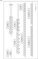
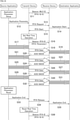
- FIG. 14 shows an example of a sequence of real-time application communication.
- FIG. 14 shows an example in which the transmitting side communication device 10Tx (Transmit Device) sets various transmission parameters when the application is started by the source application (SourceApplication).
- the process of setting the communication parameters of the real-time application is performed by the sender application on the sender side.
- the sender application when an application that delivers specific content is started, the communication parameters of the real-time application are acquired (ApplicationParameterSetup), and a series of real-time application communication request commands (ApplicationParameter) are sent side communication. It is sent to the device 10Tx (S12).
- a predetermined beacon signal is transmitted at a predetermined transmission timing (S11), but here, it indicates a state in which a real-time application is not set. It is configured to include information elements.
- the start command (ApplicationStart) is delivered to the destination application (DestinationApplication) (S14), and at the same time, the buffer capacity of the receiving side communication device 10Rx and the like.
- the processing capacity parameter is described in the start command (RTAStart) and returned (S15).
- the transmission interval (Interval) and transmission capacity (Capacity) described above are used as transmission parameters of the real-time application based on the information described in the start command (RTAStart). Is calculated, and a dedicated buffer space (for example, RTA buffer 103-1) is secured as needed (Set Real Time Operation).
- the predetermined transmission interval is determined by estimating the predetermined time interval from the time when the transmitting side communication device 10Tx receives the RTA data from the real-time application.
- the transmission capacity Capacity
- a predetermined transmission capacity is determined according to the available bandwidth at that time. do it.
- an information element indicating that these RTA parameters are set is constructed, and a beacon signal is transmitted at a predetermined transmission timing. It may be good (S16).
- These RTA parameters can be notified by transmitting a beacon signal including this information element to other communication devices existing in the vicinity.
- the transmission side communication device 10Tx stores the data in a dedicated buffer as needed, and has a predetermined transmission capacity at a predetermined transmission interval. It is transmitted as RTA data (RTA Data) of (S17, S18).
- the receiving side communication device 10Rx receives the transmitted RTA data (data for which an identifier is set), stores it in a dedicated buffer (for example, RTA receiving buffer 115-1), and stores these content data in the destination application. Is output (S19).
- the received data is RTA data
- it is stored in a dedicated buffer that preferentially outputs RTA data, and is output to the destination application according to the RTA data output format.
- the RTA data is output to the destination application before the maximum allowable delay time elapses.
- the receiving side communication device 10Rx outputs RTA data to the destination application and returns ACK information as needed (S20). If the RTA data cannot be decoded correctly, the NACK information requesting retransmission is returned.
- ACK information or NACK information is constructed based on the maximum allowable delay time.
- the transmitting side communication device 10Tx that has received the receipt confirmation (ACK / NACK) information, when the NACK information is returned, it may be retransmitted as necessary from the allowable delay time by the present technology, and the ACK information may be retransmitted. If, the transmission of RTA data at this transmission interval ends.
- the configuration is such that transmission of other communication devices and other data is performed until the next transmission interval arrives, and when the next transmission interval arrives, a series of these RTA data are transmitted. Is repeatedly carried out (S21 to S24, S25 to S28, S29 to S32).
- a real-time application opening command (ApplicationEnd) is sent to the transmitting communication device 10Tx in order to reset the RTA transmission. (S33).
- the transmitting side communication device 10Tx releases (cancels) the identifier that identifies the data (RTA data) of the real-time application, cancels the setting of the dedicated buffer space, and cancels the setting of the dedicated buffer space, and also releases the receiving side communication device 10Rx.
- a release command (RTA Release) is sent to (S34).
- the transmitting side communication device 10Tx operates as an access point, for example, in order to indicate that these RTA parameters have been released, the existing RTA information element settings are canceled and the transmission timing is determined. It may be configured to transmit a beacon signal (S36).
- the end command (ApplicationEnd) is delivered to the destination application (S35), and it is notified that the series of communication is completed.
- the release command RTA Release
- the identifier for identifying the RTA data may be released (released) and the setting of the dedicated buffer space may be released. No.
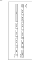
- FIG. 15 shows another example of a sequence of real-time application communication.
- FIG. 15 an example in which the transmitting side communication device 10Tx (Transmit Device) is specified and the transmitting side communication device 10Tx sets various transmission parameters when the application is started by the destination application (Destination Application). Shows.
- the process of setting the communication parameters of the real-time application is performed by the destination application on the receiving side.
- the communication parameters of the real-time application are acquired (ApplicationParameterSetup), and a series of real-time application request commands (ApplicationParameter) are sent to the receiving communication device. It is sent to 10Rx (ReceiveDevice) (S52).
- the transmitting side communication device 10Tx transmits a predetermined beacon signal at a predetermined transmission timing, for example, when operating as an access point (S51).
- the transmitting side communication device 10Tx In the receiving side communication device 10Rx that received this request command (ApplicationParameter) from the destination application, the transmitting side communication device 10Tx is specified, an identifier that identifies the data (RTA data) of the real-time application is set, and the receiving side communication is performed.
- a request command (RTARequest) including parameters of the buffer capacity and processing capacity of the device 10Rx is transmitted to the transmitting side communication device 10Tx (S53).
- a start command (ApplicationStart) is delivered to the sending application (S54), and the above-mentioned transmission interval and transmission are also used as transmission parameters of the real-time application.
- the capacity is calculated, and a dedicated buffer space (for example, RTA buffer 103-1) is secured as needed (Set Real Time Operation).
- the transmission side communication device 10Tx for example, when operating as an access point, an information element indicating that these RTA parameters are set is constructed, and a beacon signal is transmitted at a predetermined transmission timing. Good (S56). These RTA parameters can be notified by transmitting a beacon signal including this information element to other communication devices existing in the vicinity.
- the transmission side communication device 10Tx when content data arrives from the sender application at a predetermined cycle, the data is stored in a dedicated buffer as needed, and a predetermined transmission is performed at a predetermined transmission interval. It is configured to be transmitted as capacity RTA data (RTAData). Since the operation of RTA data transmission here is the same as that of FIG. 14 described above, details are omitted (S57 to S60, S61 to S64, S65 to S68, S69 to S72).
- a real-time application release command (ApplicationEnd) is sent to the receiving side communication device 10Rx in order to reset the RTA transmission (S73).
- the receiving side communication device 10Rx When the receiving side communication device 10Rx receives this notification, the identifier that identifies the data (RTA data) of the real-time application is released, and the release command (RTA Release) is transmitted to the transmitting side communication device 10Tx (S74). ).
- the transmitting side communication device 10Tx Upon receiving this release command (RTA Release), the transmitting side communication device 10Tx cancels the setting of the dedicated buffer space, and the end command (ApplicationEnd) is delivered to the sending application (S75), and a series of communication is performed. You will be notified that it has finished.
- the transmitting side communication device 10Tx operates as an access point, for example, in order to indicate that these RTA parameters have been released, the existing RTA information element settings are canceled and the transmission timing is determined. It may be configured to transmit a beacon signal (S76).
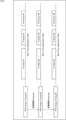
- FIG. 16 shows an example of the configuration of a communication device to which the present technology is applied.
- the communication device 10 shown in FIG. 16 is a wireless communication device configured as an access point AP10 or a communication terminal STA10 in the wireless LAN system 1-1 (FIG. 1), that is, a transmitting side communication device 10Tx or a receiving side communication device 10Rx. be.
- the communication device 10 includes a network connection module 11, an information input module 12, a device control module 13, an information output module 14, and a wireless communication module 15.
- the network connection module 11 is composed of, for example, a circuit having a function of connecting an optical fiber network or other communication line to an Internet network via a service provider as an access point AP10, peripheral circuits thereof, a microcontroller, a semiconductor memory, and the like. Will be done.
- the network connection module 11 performs various processes related to the Internet connection according to the control from the device control module 13.
- the network connection module 11 is configured to be equipped with a function such as a communication modem for connecting to the Internet network when the communication device 10 operates as an access point AP10.
- the information input module 12 is composed of input devices such as push buttons, a keyboard, and a touch panel, for example.
- the information input module 12 has a function of inputting instruction information corresponding to an instruction from the user to the device control module 13.
- the device control module 13 is composed of, for example, a microprocessor, a microcontroller, a semiconductor memory, or the like.
- the device control module 13 controls each part (module) in order to operate the communication device 10 as the access point AP10 or the communication terminal STA10.
- the device control module 13 performs various processes on the information supplied from the network connection module 11, the information input module 12, or the wireless communication module 15. Further, the device control module 13 supplies the information obtained as a result of its own processing to the network connection module 11, the information output module 14, or the wireless communication module 15.
- the device control module 13 supplies transmission data passed from an application in the upper layer of the protocol to the wireless communication module 15 when transmitting data, or receives data supplied from the wireless communication module 15 when receiving data. Is passed to applications in the upper layer of the protocol.
- the information output module 14 is composed of an output device including a display element such as a liquid crystal display, an organic EL display, and an LED (Light Emitting Diode) display, and a speaker that outputs voice or music.
- a display element such as a liquid crystal display, an organic EL display, and an LED (Light Emitting Diode) display
- a speaker that outputs voice or music.
- the information output module 14 has a function of displaying necessary information to the user based on the information supplied from the device control module 13.
- the information processed by the information output module 14 includes, for example, the operating state of the communication device 10 and information obtained via the Internet network.
- the wireless communication module 15 is composed of, for example, a wireless chip, a peripheral circuit, a microcontroller, a semiconductor memory, and the like.
- the wireless communication module 15 performs various processes related to wireless communication in accordance with the control from the device control module 13. Details of the configuration of the wireless communication module 15 will be described later with reference to FIG.
- a wireless communication module equipped with a wireless communication chip and peripheral circuits will be described as an example, but this technology is applied not only to the wireless communication module but also to, for example, a wireless communication chip and a wireless communication LSI. be able to. Further, in the wireless communication module, it is optional whether or not to include the antenna.
- the device control module 13 and the wireless communication module 15 are indispensable components, but the network connection module 11, the information input module 12, and the information output module 14 excluding them are configured. It is optional to include it in the element.
- each communication device 10 operating as an access point AP10 or a communication terminal STA10 can be configured to be composed of only required modules, and unnecessary parts are simplified or not incorporated. Can be.
- the network connection module 11 can be incorporated only in the access point AP10, and the information input module 12 and the information output module 14 can be incorporated only in the communication terminal STA10.
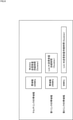
- FIG. 17 shows an example of the configuration of the wireless communication module 15 of FIG.
- the wireless communication module 15 is connected to another module, has an interface 101 for exchanging various information and data, an RTA data determination unit 102 for determining the attributes of transmission data from access categories, and temporary transmission data for each category. It is configured to include a transmission buffer 103 to be stored in.
- the transmission buffer 103 stores the RTA buffer 103-1 for storing RTA data for real-time applications, the AC_VO buffer 103-2 for storing audio data, the AC_VI buffer 103-3 for storing video data, and the best effort data.
- AC_BE buffer 103-4 and AC_BG buffer 103-5 for storing background data.
- the RTA operation management unit 104 that controls the transmission / reception operation for real-time applications, which is a characteristic configuration of the present technology
- the transmission control unit 105 that dequeues the order of transmission data
- the timing control that controls the transmission timing.
- a transmission frame construction unit 107 that constructs a data frame to be transmitted, an access control unit 108 that controls transmission and reception of data, and a transmission processing unit 109-1, 109- that performs a transmission operation at each link. 2 is included.
- the transmission processing unit 109-1 performs a transmission operation related to the first link (Link # 1).
- the transmission processing unit 109-2 performs a transmission operation related to the second link (Link # 2).
- an antenna control unit 110 is provided that controls transmission of a transmission signal from the antenna group 111 to another communication device 10 and reception of a transmission signal transmitted from the other communication device 10 via the antenna group 111. ..
- the antenna control unit 110 and the antenna group 111 may not be included in the wireless communication module 15.
- the wireless communication module 15 is configured to include reception processing units 112-1 and 112-2 at each link, which perform a reception operation using the received signal received by the antenna as a predetermined signal.
- the reception processing unit 111-1 performs a reception operation related to the first link (Link # 1).
- the reception processing unit 111-2 performs a reception operation related to the second link (Link # 2).
- It also includes a receive frame extraction unit 113 that extracts a predetermined data frame from the received signal, a data analysis unit 114 that analyzes the data included in the received data frame, and a receive buffer 115 that temporarily stores the received data. It is composed.
- the receive buffer 115 is a group of buffers composed of a receive buffer 115-2 for storing data excluding RTA data and an RTA receive buffer 115-1 as a dedicated buffer space for storing RTA data for real-time applications.
- an output data construction unit 116 that is constructed as data in the output format for delivery to a predetermined application, and finally passes data to an application of a connected device or the like via an interface 101. It has become.
- the RTA operation management unit 104 has an interface 101, a transmission control unit 105, and a timing control unit 106 in order to realize a function related to control of transmission of RTA data for a real-time application as a characteristic function of the present technology. , And in cooperation with each of the receive buffer 115.
- the access control unit 108 has a timing control unit 106, a transmission frame construction unit 107, and a transmission processing unit 109-in order to realize a function related to data transmission and reception control as a characteristic function of the present technology. It operates in cooperation with 1,109-2, the antenna control unit 110, and the reception processing units 112-1 and 112-2, respectively.
- the RTA operation management unit 104 and the access control unit 108 control the operation of each unit to perform, for example, the following processing.
- the wireless communication module 15 of the communication device 10 transmitter communication device 10Tx
- data of a specific attribute for example, RTA data
- a predetermined transmission interval (Interval) by the RTA operation management unit 104, the access control unit 108, or the like.
- the transmission capacity (Capacity) for repeatedly transmitting a predetermined amount of information is estimated, and when a transmission opportunity is acquired by random access control with another communication device (reception side communication device 10Rx), a predetermined transmission interval is obtained.
- Control is performed to determine a predetermined transmission capacity (Capacity) to be transmitted according to the elapsed time of (Interval) and transmit data of a specific attribute (for example, RTA data).
- the data transmission side communication device (sending side communication device 10Tx) and the reception side communication device are used by the RTA operation management unit 104, the access control unit 108, and the like.
- reception side communication device 10Rx and exchanging communication parameters, reception of data with specific attributes (for example, RTA data) is set, and a predetermined transmission capacity (division) is set for each predetermined transmission interval (Interval). Control is performed to periodically receive data of a specific attribute (for example, RTA data) that becomes Capacity).
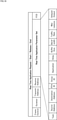
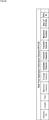
- FIG. 18 shows an example of the configuration of commands related to the setup of a real-time application.
- the configuration example shown in FIG. 18 shows a configuration according to the frame format used in the wireless LAN system, but the configuration is limited to this configuration. It does not have to be.
- This frame is configured to include Frame Control indicating the type of the frame, Duration indicating the duration, Transmit Address indicating the address of the transmitting side, and Receive Address indicating the address of the receiving side as predetermined header information. Furthermore, this frame contains a real-time application parameter set (RealTimeApplicationParameterSet), which is necessary for implementing control to which this technology is applied, and has a frame check sequence (FCS: Frame Check Sequence) at the end. It is added and configured.
- RealTimeApplicationParameterSet Real-time application parameter set
- FCS Frame Check Sequence
- This real-time application parameter set includes Type indicating the command format, Source Address indicating the source address of the sender, Destination Address indicating the destination address of the destination, RTA ID indicating the identifier of RTA, Group ID indicating the group, and application.
- Application indicating the type of, Delay indicating the allowable delay time, Buffer Size indicating the buffer size, Band-Width indicating the bandwidth information to be used, Traffic Rate indicating the transmission rate expected for traffic, Max indicating the maximum delay time. It consists of information such as Latency and Delayed Output, which indicates the data output when a delay occurs.
- the necessary parts are described and transmitted from the transmitting side, and the information is used by the receiving side.
- the example of the configuration of the real-time application parameter set shown in FIG. 18 is only an example, for example, information on the maximum allowable delay of data, information on the buffer capacity, information on the bandwidth used, and information on the bandwidth used as shown in FIG. If information such as information regarding the data output format is included as a parameter, other parameters (for example, parameters corresponding to the information shown in FIG. 19) may be included.
- FIG. 19 shows an example of the configuration of application parameters.
- the parameters of this application are the parameters exchanged between the application device and the communication device 10.
- An application device is a device equipped with a specific application such as a real-time application.
- FIG. 19 a configuration according to the frame format used in the wireless LAN system is shown, and as predetermined header information, Frame Control indicating the type of frame, Duration indicating the duration, and the address on the transmitting side are shown.
- the Transmit Address and Receive Address indicating the address of the receiving side are described, but they may be added or deleted as necessary.
- the parameters actually exchanged are described as an application parameter set (ApplicationParameterInformation), and FCS is further added.
- This parameter is the Type that indicates the notification of the application parameter (ApplicationParameter), the start of the application (ApplicationStart), or the end of the application (ApplicationEnd), the SourceAddress that indicates the address of the sender, and the destination side.
- the destination address which indicates the address of, is configured so that the parameters corresponding to each application are described.
- the parameters corresponding to this application are, for example, Application Type indicating the application format in the case of moving image information, Frame Size indicating the frame size of the data, Frame Rate indicating the frame rate, Max Latency indicating the maximum delay time, and buffer. It consists of BufferSize, which indicates the size, OutputType, which indicates the format for outputting data, OutputDelay, which indicates the output delay time, and RTAAttribute, which indicates the attributes of the real-time application.
- the transmission interval (Interval) and the transmission capacity (Capacity) regarding the RTA data transmitted by wireless communication are calculated with reference to these parameters. It has become.
- the maximum allowable delay time is calculated from information such as Application Type indicating the application format, Output Type indicating the data output format, and Output Delay indicating the output delay time, and the maximum allowable delay time is calculated in FIG.
- the configuration that determines the transmission interval (Interval) and transmission capacity (Capacity) from information such as Frame Size indicating the frame size and Frame Rate indicating the frame rate taking into account the indicated input processing delay time and output processing delay time. It has become.
- parameters may be estimated using other parameters or the like.
- parameters may be included as parameters according to the application.
- information such as information on the maximum allowable delay of data, information on the buffer capacity, and information on the output format of the data as shown in FIG. 19 is included as parameters, other parameters may be used. Parameters may be included.
- FIG. 20 shows an example of the configuration of an information element that notifies the settings of a real-time application.
- This information element is included in, for example, a beacon frame, etc., and is notified to transmit data related to a real-time application to other communication devices in the vicinity, and the transmission interval, transmission capacity, duration, and the like. Parameters can be notified.
- This information element is as follows: Element ID indicating the element identifier, Length indicating the information length, Type indicating the format, Maximum Latency indicating the maximum allowable delay time, Average Latency indicating the average delay time, and Available indicating the available channels. Various parameters such as Channel, Transmit Capacity indicating transmission capacity, Transmit Interval indicating transmission interval, and Maximum Duration indicating maximum duration are described.
- FIG. 21 shows an example of a frame configuration of real-time application data.
- an identifier or a flag for identifying real-time application data is stored in the header part of the data, so that a buffer (for example, RTA reception) for which priority processing is performed by the receiving side communication device 10Rx is performed. It is used to facilitate the storage of data in the buffer 115-1).
- a configuration is shown in which a flag for identifying RTA ID or RTA data is prepared in the SIG-A field of the PLCP (Physical Layer Convergence Protocol) header.
- DM Physical Layer Convergence Protocol
- the free bit of the delimiter (DM: Delimiter) added before the MPDU (MAC Protocol Data Unit) constituting the PPDU (PLCP Protocol Data Unit) is used, and the data of the MPDU is used. It may be possible to set a flag (ASAP) indicating that the data is processed promptly.
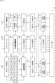
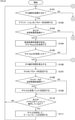
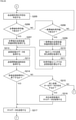
- step S101 the RTA operation management unit 104 determines whether the application that executes RTA communication is started and activates RTA communication, and if it is determined that the application that executes RTA communication is started (S101). "YES"), the process proceeds to step S102.
- step S102 the RTA operation management unit 104 acquires the parameters of the started application (for example, the parameters shown in FIG. 19).
- step S103 the RTA operation management unit 104 determines whether the own device is the transmitting side communication device 10Tx, and if the own device is determined to be the transmitting side communication device 10Tx (“YES” in S103), processing. Is advanced to step S104.
- step S104 the RTA operation management unit 104 identifies the receiving side communication device 10Rx and transmits an RTA Request command.
- step S105 when the RTA operation management unit 104 determines whether the RTA Start command has been received from the receiving side communication device 10Rx and determines that the RTA Start command has been received (“YES” in S105), the process is The process proceeds to step S106, and the processing of steps S106 and S107 is executed by the RTA operation management unit 104.
- the transmitting side communication device 10Tx (“YES” in S103) and receiving the RTA Start command (for example, the parameter information included in the command shown in FIG. 18) from the receiving side communication device 10Rx.
- the operating time of the real-time application is calculated (S106), and the parameters of these RTAs are set (S107). If the RTA Start command has not been received until a predetermined time (“NO” in S105), the parameters may be reset and the RTA Request command may be retransmitted.
- step S108 the RTA operation management unit 104 determines whether or not the RTA data transmission side communication device 10Tx is used, and if it is determined that the RTA data transmission side communication device 10Tx is used (“YES” in S108), processing is performed. Is advanced to step S109.
- step S109 the RTA operation management unit 104 sets the RTA ID identifier and the dedicated transmission buffer 103 (RTA buffer 103-1) as necessary.
- step S110 the RTA operation management unit 104 determines whether or not the own device is operating as an access point, and if it is determined that the own device is operating as an access point (“YES” in S110), the process is performed. , Step S111.
- step S111 the RTA operation management unit 104 sets the RTA IE in which these parameters are described, adds the RTA IE to the beacon frame, and transmits the RTA IE.
- step S111 If the process of step S111 is completed or the determination process of step S110 determines that the access point is not operating, the process returns to step S101, and the subsequent processes are repeated.
- step S101 determines whether RTA communication has been activated. If it is determined in the determination process of step S101 that RTA communication has not been activated, the process proceeds to step S112 of FIG.
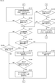
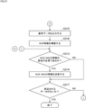
- step S112 when the RTA operation management unit 104 determines whether the RTA Request command has been received from the receiving side communication device 10Rx and determines that the RTA Request command has been received (“YES” in S112), the process is The process proceeds to step S113, and the processing of steps S113 and S114 is executed by the RTA operation management unit 104.
- the transmitting side communication device 10Tx receives the RTA Request command from the receiving side communication device 10Rx (“YES” in S112), the request is made. If the RTA can be set with reference to the parameters (“YES” in S113), the parameters of the corresponding application (eg, the parameters shown in FIG. 19) are acquired (S114). Then, the process proceeds to step S106 of FIG. 22 described above, and the RTA parameters are set.
- step S103 If it is determined in the determination process of step S103 that the own device is the receiving side communication device 10Rx (“NO” in S103), the process proceeds to step S115 of FIG.
- step S115 the RTA operation management unit 104 identifies the transmitting side communication device 10Tx and transmits an RTA Request command.
- step S116 the RTA operation management unit 104 determines whether or not the RTA Start command has been received from the transmitting side communication device 10Tx, and if it is determined that the RTA Start command has been received (“YES” in S116), The process proceeds to step S117, and the process after step S117 is executed by the RTA operation management unit 104. If it is determined that the RTA Start command has not been received until a predetermined time (“NO” in S116), the parameter may be reset and the RTA Request command may be retransmitted.
- step S112 when it is determined in the determination process of step S112 that the RTA Request command has not been received (“NO” in S112), or when it is determined in the determination process of step S113 that the RTA cannot be set. (“NO” in S113), the process proceeds to step S117.
- RTA buffer 103-1 The set RTA ID identifier and the dedicated transmission buffer 103 (RTA buffer 103-1) are released as necessary (S119). If the own device is operating as an access point (“YES” in S120), RTAIE is set to describe that these parameters have been released, and is added to the beacon frame for transmission (“YES”). S121).
- the RTA Release command is transmitted to the transmitting side communication device 10Tx (S122). Further, when it is determined in the determination process of step S117 that the RTA communication is not terminated (“NO” in S117) and the RTA Release command is received (“YES” in S123), the communication on the receiving side is performed. Since the RTA Release command has been received from the device 10Rx, the process proceeds to step S119, and the RTA communication parameter is released.
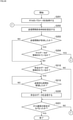
- step S201 the RTA operation management unit 104 acquires the transmission parameter of the real-time application, and sets the arrival time of the timing corresponding to the interval according to the transmission interval set as the acquired transmission parameter (S202).
- step S203 the RTA operation management unit 104 determines whether or not the set transmission interval has arrived, and if it is determined that the transmission interval has arrived (“YES” in S203), the process proceeds to step S204.
- step S204 the transmission control unit 105 determines whether the RTA data is stored in the predetermined transmission buffer 103 (RTA buffer 103-1), and if it is determined that the RTA data is stored (“S204”, “ YES ”), the process proceeds to step S205 of FIG.
- step S205 the access control unit 108 determines whether or not the wireless transmission line can be used, and the processes of steps S206 to S213 are executed according to the determination result.
- the transmission capacity duration of the entire band is acquired (S207).
- the transmission capacity duration of the part of the band is acquired (S209), and the transmission of another link is awaited. Time is acquired (S210), and based on the acquired information, the transmission capacity with only available links is calculated (S211).
- step S213 the process proceeds to step S214.
- step S215 the RTA operation management unit 104 determines whether or not the transmission of the transmission capacity is completed within the allowable transmission time based on the elapsed time in the acquired current transmission interval, and the transmission control is performed according to the determination result.
- the processing of steps S215 to S217 is executed by the unit 105, the access control unit 108, and the like.
- step S217 If it is determined that the process of step S217 is completed or that the data to be transmitted does not exist in the determination process of step S215 (“NO” in S215), the process returns to step S202 of FIG. 24. , Subsequent processing is repeated.
- step S203 determines whether the transmission control unit 105 determines whether the conventional access category data (voice data or the like), that is, predetermined data is stored in the transmission buffer 103, and the transmission control is performed according to the determination result.
- the processing of steps S219 to S221 is executed by the unit 105, the access control unit 108, and the like.
- step S301 the data analysis unit 114 acquires the received data obtained by the control of the access control unit 108 or the like, determines whether the acquired received data is the data addressed to itself (S302), and the self-addressed data. Performs determination processing (S303) as to whether the received data is RTA data.
- steps S302 and S303 if the received data is data addressed to itself (“YES” in S302) and is RTA data (“YES” in S303), the process is performed in step S304.
- the process is advanced, and the processes of steps S304 to S312 are executed by the RTA operation management unit 104, the data analysis unit 114, the access control unit 108, and the like.
- the parameters of the set real-time application are referenced (S304) and the data arrives within the allowable delay time (“YES” in S305), the receipt confirmation (ACK / NACK) information is displayed. It is constructed (S306). Then, when all the data of the transmission capacity at one time can be collected (“YES” in S307), the RTA data is output to the application after the output time of the data has arrived (“YES” in S308). (S309).
- delayed ACK information is constructed. (S311), and RTA data is output to the application (S309).
- the delayed NACK information is constructed and the RTA data is discarded without being output.
- step S313 the data analysis unit 114 determines whether or not the receipt confirmation (ACK / NACK) information needs to be returned, and when it is determined that the receipt confirmation (ACK / NACK) information needs to be returned (S313). "YES"), the process proceeds to step S314.
- step S314 the access control unit 108 or the like transmits the receipt confirmation (ACK / NACK) information.
- step S303 of FIG. 26 determines whether the data is RTA data in the determination process of step S303 of FIG. 26 is, for example, it is determined to be normal data (“NO” in S303).
- the process proceeds to step S315 of FIG. 27.
- RTA operation management unit 104, data analysis unit 114, access control unit 108, and the like execute the processes of steps S315 and S316.
- step S317 the data analysis unit 114 determines whether or not there is data to be retransmitted, and if there is no data to be retransmitted (“YES” in S317), a series of reception processes is terminated. If there is data to be retransmitted (“NO” in S317), the process returns to step S301 in FIG. 26, and the data reception process is continued.
- the transmitting side communication device 10Tx can be configured as, for example, an access point AP10 (base station), and the receiving side communication device 10Rx can be configured, for example, as a communication terminal STA10 (terminal station).
- the transmitting side communication device 10Tx or the receiving side communication device 10Rx is configured to be configured as a part (for example, a wireless communication module, a wireless chip, etc.) of the devices (parts) constituting the access point AP10 or the communication terminal STA10. May be good.
- the receiving side communication device 10Rx configured as the communication terminal STA10 may be a wireless device such as a smartphone, a tablet terminal, a game device, a mobile phone, a personal computer, a digital camera, a television receiver, a wearable terminal, or a speaker device. It can be configured as an electronic device having a communication function.
- the communication terminal STA10 supports only the reception of data such as a device such as a controller that transmits command data according to a user's operation and a display device that receives and displays video data. It may be a device.
- a wireless communication method in which a random access control delay occurs like a wireless LAN system so that the content specified by a user operating in a specific application such as a real-time application can be output with a short delay time. Also, in order to suppress the influence of delay as much as possible, we propose a priority transmission control method that can transmit a certain amount of information in a predetermined cycle.
- a wireless communication device and a wireless communication method that preferentially transmit data so that transmission opportunities can be obtained periodically. That is, in order to suppress the influence of delay as much as possible, we are proposing a wireless communication device and a wireless communication method in which a fixed amount of data is preferentially transmitted in a predetermined cycle.
- the data to be preferentially transmitted may be content data specified in advance by the user, may be data of a specific application, may be a predetermined data type, and may be within a specific time. It may be data directed from a specific communication device to a specific communication device, or it may be data for a group of these communication devices, and an identifier (flag) indicating that any of these data groups are output with a short delay time. ) Is set, and access control is implemented so that transmission opportunities are preferentially obtained at predetermined cycles.
- the frequency of priority transmission is controlled, and in order to avoid unnecessary transmission, the capacity of one transmission and the interval of priority transmission It is configured to set the transmission interval. If the data is transmitted within the transmission interval, the data is not transmitted until the next transmission interval arrives, but the data is used for transmission of another communication device, and the transmission path is used more than necessary. It is configured not to occupy.
- a predetermined transmission interval is determined in advance and data transmission is performed within the transmission interval, data transmission is not performed until the next transmission interval arrives, and the data is transmitted to another communication device. It is a communication control method that does not occupy the transmission line more than necessary.
- the maximum delay time information that allows the output of the content of a specific application the information of the reception cycle in which the data information of the content is delivered, and the communication on the receiving side. From the buffer capacity information of the device, the delay status of the access control of the transmission line, etc., the amount of one transmission information is set as the transmission capacity, calculated according to the bandwidth information of the link, and this is transmitted within the allowable delay time.
- the receiving status of the data to be transmitted is monitored by the transmitting communication device, and when the data addressed to a specific communication device is periodically transmitted, the above maximum It may be configured to estimate the allowable delay time.
- the data in which these identifiers are described may be stored in a dedicated transmission buffer, and by performing control for preferentially transmitting from the transmitting side communication device to the receiving side communication device based on the transmission parameter.
- the configuration may be such that the real-time communication desired by a specific application is realized.
- the transmission opportunity is prioritized in a predetermined cycle.
- the effect of delay due to access control can be suppressed as much as possible.
- a predetermined transmission interval is determined in advance and data transmission is performed within that transmission interval, data transmission is not performed until the next transmission interval arrives, and the data is transmitted to another communication device.
- data it is possible to obtain a method of using the transmission line fairly with other data without occupying the transmission line more than necessary.
- the allowable delay time is determined and data transmission cannot be started by the allowable delay time, access is performed by temporarily increasing the transmission capacity together with the data to be transmitted at the next transmission interval. Control delay can be suppressed.
- identifiers For data to be sent preferentially, content data specified in advance by the user, data of a specific application, content data defined by a predetermined attribute, within a specific time Any data group can be output with a short delay time according to the needs of the user, such as data directed from a specific communication device to a specific communication device, data for a group of these communication devices, and the like.
- the data can be distinguished from other data, and the transmission side communication device can be transferred to the reception side communication device based on a predetermined transmission parameter. It is possible to implement control for preferential transmission.
- the processes performed by the computer according to the program do not necessarily have to be performed in chronological order in the order described as the flowchart. That is, the processing performed by the computer according to the program includes processing executed in parallel or individually (for example, processing by parallel processing or processing by an object).
- the program may be processed by one computer (processor) or may be distributed processed by a plurality of computers.
- the program may be transferred to a distant computer for execution.
- system means a set of a plurality of components (devices, modules (parts), etc.), and it does not matter whether all the components are in the same housing.
- each step described in the above flowchart can be executed by one device or can be shared and executed by a plurality of devices. Further, when a plurality of processes are included in one step, the plurality of processes included in the one step can be executed by one device or shared by a plurality of devices.
- (1) Estimate the transmission capacity for repeatedly transmitting the data of a specific attribute at a predetermined transmission interval with a predetermined amount of information.
- a predetermined transmission capacity to be transmitted is determined according to the elapsed time of a predetermined transmission interval, and data of the specific attribute is controlled to be transmitted.
- a communication device equipped with a control unit. (2) The communication device according to (1) above, wherein the control unit stops the transmission of data having the specific attribute until a predetermined transmission interval arrives after transmission of data having a predetermined transmission capacity.
- the control unit adds the transmission capacity to be transmitted at the next transmission interval.
- the control unit sets a predetermined transmission interval and a predetermined transmission capacity by specifying a data transmission side communication device and a reception side communication device and exchanging communication parameters. Communication device described in Crab.
- the control unit transmits a request for the communication parameter including information on the maximum allowable delay of the data, information on the buffer capacity, information on the bandwidth used, and information on the output format of the data to the data receiving side communication device.
- the communication device according to (4).
- the control unit Set an identifier to identify data of a specific attribute, The communication device according to any one of (1) to (5), wherein the set identifier is added to the data of the specific attribute transmitted at a predetermined transmission interval.
- It also has a buffer to store data for specific attributes specified by the user.
- the communication device according to any one of (1) to (6), wherein the control unit transmits data of the specific attribute stored in the buffer when the transmission opportunity is acquired.
- the control unit determines a predetermined transmission interval by estimating a predetermined time interval from the time when the data transmitting side communication device receives data of a specific attribute from the application.
- the control unit estimates a predetermined amount of information that can be transmitted at a predetermined transmission interval based on information on the maximum allowable delay of data, information on the buffer capacity of the receiving side communication device, and information on the bandwidth used.
- the communication device according to any one of (1) to (8) above, which determines a predetermined transmission capacity.
- the communication device determines a predetermined transmission capacity.
- the control unit determines a predetermined transmission capacity according to the available bandwidth at that time.
- (11) The communication device according to (6) above, wherein the control unit cancels the setting of the identifier when the transmission of the data of the specific attribute is completed.
- the communication device Estimate the transmission capacity for repeatedly transmitting the data of a specific attribute at a predetermined transmission interval with a predetermined amount of information. Communication that controls the transmission of data of the specific attribute by determining a predetermined transmission capacity to be transmitted according to the elapsed time of a predetermined transmission interval when a transmission opportunity is acquired by random access control with another communication device. Method. (13) By specifying the data transmitting side communication device and the receiving side communication device and exchanging communication parameters, it is possible to set the reception of data with a specific attribute.
- a communication device including a control unit that controls to periodically receive data of the specific attribute having a predetermined transmission capacity at a predetermined transmission interval.
- control unit transmits a notification of the communication parameter including information on the maximum allowable delay of data, information on the buffer capacity, information on the bandwidth used, and information on the output format of the data. ..
- the control unit Of the received data the data for which a specific identifier is set is recognized as the data with the specific attribute, and the data is recognized.
- the communication device according to (14) above which stores the data of the specific attribute in a buffer that preferentially outputs the data.
- control unit outputs received data of the specific attribute to an application before the maximum allowable delay time elapses.
- the control unit outputs the data of the specific attribute to the application based on the output format of the data of the specific attribute when the data in which the specific identifier is set is received. Communication device.
- the communication device By specifying the data transmitting side communication device and the receiving side communication device and exchanging communication parameters, it is possible to set the reception of data with a specific attribute.
- a communication method for controlling periodic reception of data of the specific attribute having a predetermined transmission capacity at a predetermined transmission interval.
- 1-1 Wireless LAN system 10 communication device, 11 network connection module, 12 information input module, 13 device control module, 14 information output module, 15 wireless communication module, 101 interface, 102 RTA data judgment unit, 103 transmission buffer, 103 -1 RTA buffer, 103-2 AC_VO buffer, 103-3 AC_VI buffer, 103-4 AC_BE buffer, 103-5 AC_BG buffer, 104 RTA operation management unit, 105 transmission control unit, 106 timing control unit, 107 transmission frame construction unit.
- 108 access control unit, 109-1, 109-2 transmission processing unit, 110 antenna control unit, 111 antenna group, 112-1, 112-2 reception processing unit, 113 reception frame extraction unit, 114 data analysis unit, 115 reception Buffer, 115-1 RTA receive buffer, 115-2 receive buffer, 116 output data construction unit
Abstract
The present technology pertains to a communication device and a communication method which make it possible to preferably transmit data on a specific attribute more suitably. Provided is a communication device comprising a control unit which estimates a transmission capacity for transmitting the data on a specific attribute repeatedly by a prescribed amount of information for each prescribed transmission interval, and performs control for determining a prescribed transmission capacity to be transmitted according to an elapsed time of the prescribed transmission interval, and transmitting the data on the specific attribute, when a transmission opportunity is acquired by a random access control with another communication device. The present technology can be applied to, for example, an apparatus that constitutes a wireless LAN system.
Description
本技術は、通信装置、及び通信方法に関し、特に、より適切に、特定の属性のデータを優先的に送信することができるようにした通信装置、及び通信方法に関する。
The present technology relates to a communication device and a communication method, and more particularly to a communication device and a communication method capable of preferentially transmitting data of a specific attribute.
無線LAN(Local Area Network)システムでは、複数の通信装置の間でネットワークを構築して運用されることから、任意の通信装置は、所定のランダムな送信待ち時間の経過後にデータを送信することができるアクセス制御方法が採用されていた。
In a wireless LAN (Local Area Network) system, a network is constructed and operated between a plurality of communication devices, so that any communication device can transmit data after a predetermined random transmission waiting time has elapsed. An access control method that can be used was adopted.
また、リアルタイムアプリケーション向けのデータを送信する際には、より短いレイテンシが要求されるため、他のデータよりも優先的に送信することが求められる。このようなデータを優先的に送信するための技術としては、例えば、特許文献1,2に開示されている技術が知られている。
Also, when transmitting data for real-time applications, shorter latency is required, so it is required to send data with priority over other data. As a technique for preferentially transmitting such data, for example, the techniques disclosed in Patent Documents 1 and 2 are known.
特許文献1には、スケジューリングにより計算された新たな優先度に関する情報を、改めてスケジューリング手段がデータに付与し、送信制御手段が送信キューに記憶されたデータに付与されている新たな優先度に関する情報を基に送信待ち時間を設定する構成が開示されている。
In Patent Document 1, information on a new priority calculated by scheduling is added to the data again by the scheduling means, and information on the new priority given to the data stored in the transmission queue by the transmission control means. A configuration for setting the transmission waiting time based on the above is disclosed.
特許文献2には、複数の通信プロトコルで受信した複数のパケットから属性情報を抽出し、抽出された属性情報の構成に基づいて、複数のパケットについて複数の通信プロトコルに共通の優先順位を決定し、決定した優先順位に基づいてパケットを処理する技術が開示されている。
In Patent Document 2, attribute information is extracted from a plurality of packets received by a plurality of communication protocols, and a priority common to the plurality of communication protocols is determined for the plurality of packets based on the configuration of the extracted attribute information. , A technique for processing a packet based on a determined priority is disclosed.
ところで、無線LANシステムのようなランダムなアクセス制御遅延が生じる環境で、より短いレイテンシが要求されるデータを、優先すべきデータとして送信するに際して、優先して送信することができない場合があり、より適切に、特定の属性のデータを優先的に送信するための技術が求められていた。
By the way, in an environment where random access control delay occurs such as a wireless LAN system, when transmitting data that requires shorter latency as data that should be prioritized, it may not be possible to preferentially transmit it. Appropriately, there has been a demand for a technique for preferentially transmitting data of a specific attribute.
本技術はこのような状況に鑑みてなされたものであり、より適切に、特定の属性のデータを優先的に送信することができるようにするものである。
This technology was made in view of such a situation, and makes it possible to more appropriately transmit data of a specific attribute with priority.
本技術の一側面の通信装置は、特定の属性のデータを、所定の送信間隔ごとに、所定の情報量を繰り返して送信するための送信容量を見積もり、他の通信装置とランダムアクセス制御によって送信機会を獲得した場合、所定の送信間隔の経過時間に応じて送信すべき所定の送信容量を決定して、前記特定の属性のデータを送信する制御を行う制御部を備える通信装置である。
The communication device of one aspect of the present technology estimates the transmission capacity for repeatedly transmitting a predetermined amount of information at a predetermined transmission interval, and transmits the data of a specific attribute with another communication device by random access control. It is a communication device including a control unit that controls to transmit data of the specific attribute by determining a predetermined transmission capacity to be transmitted according to an elapsed time of a predetermined transmission interval when an opportunity is acquired.
本技術の一側面の通信方法は、通信装置が、特定の属性のデータを、所定の送信間隔ごとに、所定の情報量を繰り返して送信するための送信容量を見積もり、他の通信装置とランダムアクセス制御によって送信機会を獲得した場合、所定の送信間隔の経過時間に応じて送信すべき所定の送信容量を決定して、前記特定の属性のデータの送信を制御する通信方法である。
In the communication method of one aspect of the present technology, the communication device estimates the transmission capacity for repeatedly transmitting the data of a specific attribute at a predetermined transmission interval with a predetermined amount of information, and is random with other communication devices. It is a communication method that controls the transmission of data of the specific attribute by determining a predetermined transmission capacity to be transmitted according to the elapsed time of a predetermined transmission interval when a transmission opportunity is acquired by access control.
本技術の一側面の通信装置、及び通信方法においては、特定の属性のデータを、所定の送信間隔ごとに、所定の情報量を繰り返して送信するための送信容量が見積もられ、他の通信装置とランダムアクセス制御によって送信機会が獲得された場合、所定の送信間隔の経過時間に応じて送信すべき所定の送信容量が決定されて、前記特定の属性のデータが送信される。
In the communication device and communication method of one aspect of the present technology, the transmission capacity for repeatedly transmitting a predetermined amount of information at a predetermined transmission interval is estimated, and other communication is performed. When a transmission opportunity is acquired by the device and random access control, a predetermined transmission capacity to be transmitted is determined according to the elapsed time of a predetermined transmission interval, and data of the specific attribute is transmitted.
本技術の一側面の通信装置は、データの送信側通信装置と受信側通信装置を特定して通信パラメータを交換することで、特定の属性のデータの受信を設定し、所定の送信間隔ごとに、所定の送信容量となる前記特定の属性のデータを定期的に受信する制御を行う制御部を備える通信装置である。
The communication device of one aspect of the present technology sets the reception of data of a specific attribute by specifying the data transmission side communication device and the reception side communication device and exchanging communication parameters, and at predetermined transmission intervals. , A communication device including a control unit that controls to periodically receive data of the specific attribute having a predetermined transmission capacity.
本技術の一側面の通信方法は、通信装置が、データの送信側通信装置と受信側通信装置を特定して通信パラメータを交換することで、特定の属性のデータの受信を設定し、所定の送信間隔ごとに、所定の送信容量となる前記特定の属性のデータの定期的な受信を制御する通信方法である。
In the communication method of one aspect of the present technology, the communication device sets the reception of data of a specific attribute by specifying the data transmission side communication device and the reception side communication device and exchanging communication parameters, and a predetermined value is provided. It is a communication method that controls periodical reception of data of the specific attribute having a predetermined transmission capacity for each transmission interval.
本技術の一側面の通信装置、及び通信方法においては、データの送信側通信装置と受信側通信装置を特定して通信パラメータを交換することで、特定の属性のデータの受信が設定され、所定の送信間隔ごとに、所定の送信容量となる前記特定の属性のデータが定期的に受信される。
In the communication device and the communication method of one aspect of the present technology, the reception of data of a specific attribute is set and predetermined by specifying the data transmission side communication device and the reception side communication device and exchanging communication parameters. Data of the specific attribute having a predetermined transmission capacity is periodically received at each transmission interval of.
なお、本技術の一側面の通信装置は、独立した装置であってもよいし、1つの装置を構成している内部ブロックであってもよい。
The communication device on one side of the present technology may be an independent device or an internal block constituting one device.
<1.本技術の実施の形態>
<1. Embodiment of this technology>
従来から無線LANシステムでは、複数の通信装置の間でネットワークを構築して運用されることから、任意の通信装置は、所定のランダムな送信待ち時間の経過後にデータを送信することができるアクセス制御方法が採用されていた。
Conventionally, in a wireless LAN system, a network is constructed and operated between a plurality of communication devices, so that any communication device can transmit data after a predetermined random transmission waiting time has elapsed. The method was adopted.
あるいは、通信チャネルでの送信に輻輳が起きないように、予め広帯域のチャネルを確保しておき、任意のチャネルを利用することで、短い送信待ち時間でデータを送信する方法が考案されていた。
Alternatively, a method has been devised in which a wideband channel is secured in advance so that transmission on a communication channel does not cause congestion, and data is transmitted with a short transmission waiting time by using an arbitrary channel.
一方、3GPP(Third Generation Partnership Project)で規格化された公衆系通信システムでは、特定の通信事業者にその通信資源の管理が任されていることから、事業者が決めた所定の遅延時間内に所望のデータを滞りなく送信することが可能とされていた。
On the other hand, in public communication systems standardized by 3GPP (Third Generation Partnership Project), the management of communication resources is entrusted to a specific telecommunications carrier, so within the predetermined delay time determined by the telecommunications carrier. It has been possible to transmit desired data without delay.
これらの通信は、通信端末に対して基地局から周波数資源が割当てて利用するシステムになっているため、この周波数資源が割り当てられれば、特定の通信装置から遅延なくデータを送信する仕組みを提供することが容易であった。
Since these communications are systems in which frequency resources are allocated from the base station to the communication terminal and used, if these frequency resources are allocated, a mechanism for transmitting data from a specific communication device without delay is provided. It was easy.
つまり、公衆系通信システムでは、周波数資源が潤沢に利用できるため、予め制御用の通信チャネルを確保しておくことで、この制御チャネルを利用して、データ送信に係るチャネルの設定を行う技術が一般的に利用されていた。
In other words, in public communication systems, frequency resources can be abundantly used, so by securing a communication channel for control in advance, a technology for setting a channel related to data transmission using this control channel is available. It was commonly used.
IEEE802.11系の無線通信プロトコルが適用される無線LANシステムでは、リアルタイムアプリケーション向けのデータを送信する場合においても、従来の無線通信プロトコルで定義されたように、他の無線通信装置と伝送路を公平に利用することが求められている。
In a wireless LAN system to which the IEEE802.11 wireless communication protocol is applied, even when transmitting data for real-time applications, as defined by the conventional wireless communication protocol, the transmission path is connected to other wireless communication devices. It is required to use it fairly.
特に、IEEE802.11規格書では、EDCA(Enhanced Distributed Channel Access)制御によって、送信するデータのアクセスカテゴリ(AC:Access Category)に基づいて、送信待ち時間を設定する技術が開示されている。
In particular, the IEEE 802.11 standard document discloses a technology for setting the transmission waiting time based on the access category (AC: Access Category) of the data to be transmitted by EDCA (Enhanced Distributed Channel Access) control.
そのため、IEEE802.11の次世代技術として、これら低レイテンシが要求されるデータを専用の送信バッファに格納して、他のデータよりも優先的に送信することのできる技術が開示されている。
Therefore, as the next-generation technology of IEEE802.11, a technology that can store these data requiring low latency in a dedicated transmission buffer and transmit them with priority over other data is disclosed.
上述した特許文献1には、スケジューリングにより計算された新たな優先度に関する情報を、改めてスケジューリング手段がデータに付与し、送信制御手段が送信キューに記憶されたデータに付与されている新たな優先度に関する情報を基に送信待つ時間を設定する技術が開示されているのは先に述べた通りである。
In Patent Document 1 described above, the scheduling means again assigns information on the new priority calculated by scheduling to the data, and the transmission control means assigns the new priority to the data stored in the transmission queue. As mentioned above, the technology for setting the transmission waiting time based on the information regarding the above is disclosed.
上述した特許文献2には、複数の通信プロトコルで受信した複数のパケットから属性情報を抽出し、抽出された属性情報の構成に基づいて、複数のパケットについて複数の通信プロトコルに共通の優先順位を決定し、決定した優先順位に基づいてパケットを処理する技術が開示されているのは先に述べた通りである。
In Patent Document 2 described above, attribute information is extracted from a plurality of packets received by a plurality of communication protocols, and a priority common to the plurality of communication protocols is given to the plurality of packets based on the configuration of the extracted attribute information. As mentioned above, a technique for determining and processing a packet based on the determined priority is disclosed.
IEEE 802.11-19/1851r1に開示された技術によれば、複数のリンクを用いて伝送する場合に、リンクごとにLink Loadを規定し、Link Loadが高いリンク(Link #2)では、低いレイテンシのデータのみを送信し、Link Loadが低いリンク(Link #1)では、低いレイテンシのデータとそれ以外のデータの双方を送信する技術が開示されている。
According to the technology disclosed in IEEE 802.11-19 / 1851r1, when transmitting using multiple links, Link Load is specified for each link, and for links with high Link Load (Link # 2), the latency is low. For links (Link # 1) that transmit only data and have a low Link Load, a technique for transmitting both low latency data and other data is disclosed.
ところで、無線LANシステムの場合、自己の周囲に送信待ちをしている通信装置が多数存在する場合には、ランダムな送信待ち時間が経過しても、他の通信装置からの送信が行われており、自己の送信ができないケースが存在した。
By the way, in the case of a wireless LAN system, if there are many communication devices waiting for transmission around itself, transmission from other communication devices is performed even if a random transmission waiting time has elapsed. In some cases, it was not possible to send it by itself.
これより、所定の遅延時間内で送信することが求められる信頼性が必要とされるデータを、素早く送信することが難しいとされていた。
From this, it was considered difficult to quickly transmit data that requires reliability, which is required to be transmitted within a predetermined delay time.
特に、時間的な制約に基づいてパスワードの入力が求められる場合など、これらの高信頼性が必要とされるデータは極力短時間のうちに送信することが求められていた。
In particular, when password input was required due to time constraints, it was required to send these data requiring high reliability in the shortest possible time.
さらに、無線LANシステムでは、他の通信装置からのデータ送信を公平に実施させるために、一旦データ送信が終了した後には、所定の送信待ち時間を再設定しなければ、再度データを送信することができないために、この送信待ち時間の再設定によって、遅延が延々と収束しなくなる問題が存在していた。
Furthermore, in the wireless LAN system, in order to allow data transmission from other communication devices to be carried out fairly, once the data transmission is completed, the data is transmitted again unless the predetermined transmission waiting time is reset. There was a problem that the delay did not converge endlessly due to this resetting of the transmission waiting time.
また、無線LANシステムの場合、送信側通信装置の周囲でデータ伝送が行われていなければ、データが送信されるものであるが、受信側通信装置の周囲で通信が行われていると、このデータを正しく復号できなくなるという問題が存在していた。
Further, in the case of a wireless LAN system, data is transmitted if data is not transmitted around the transmitting side communication device, but if communication is performed around the receiving side communication device, this is the case. There was a problem that the data could not be decoded correctly.
一方、公衆系通信システムにおいては、特定の通信装置から遅延なくデータを送信する仕組みを提供することが容易であるが、その通信を実施するには、特定の通信事業者の提供するネットワークに組み込まれて、かつ、所定の利用費用を支払わなければならず、コストがかかるという問題があった。
On the other hand, in a public communication system, it is easy to provide a mechanism for transmitting data from a specific communication device without delay, but in order to carry out the communication, it is incorporated into a network provided by a specific communication carrier. In addition, there is a problem that a predetermined usage fee must be paid, which is costly.
また、近年、爆発的なデータ通信の需要によって、潤沢に存在した周波数資源の利用が増加してしまって、データ通信用のチャネルを確保しておくことが難しくなってきている。
Also, in recent years, due to the explosive demand for data communication, the use of abundant frequency resources has increased, and it has become difficult to secure a channel for data communication.
従来からの無線LANシステムにおける、データ送信の優先順序の規定では、送信するデータのアクセスカテゴリによって、順位が決定されていたため、リアルタイムアプリケーションによって短いレイテンシが求められるデータについても、この仕組みに基づいて送信制御が実施されていた。
In the conventional wireless LAN system, the order of priority for data transmission is determined by the access category of the data to be transmitted. Therefore, even data that requires a short latency by a real-time application is transmitted based on this mechanism. Control was in place.
そのため、リアルタイムアプリケーションで送信されるデータが、他のアクセスカテゴリで優先度の高いデータが存在した場合には、そのデータの送信が優先され、所望のレイテンシ要求を満たすことができなくなる可能性があった。
Therefore, if the data transmitted by the real-time application has high priority data in other access categories, the transmission of the data is prioritized and there is a possibility that the desired latency request cannot be satisfied. rice field.
これらを解決し得る技術提案においても、低レイテンシが要求されるデータを専用の送信バッファに格納して、他のデータよりも優先的に送信する技術では、そのバッファに格納されたデータばかりが短い送信待ち時間が設定されるため、それらのデータ以外のデータの送信機会が到来しなくなるという問題があった。
Even in the technical proposals that can solve these problems, in the technology of storing data requiring low latency in a dedicated transmission buffer and transmitting it with priority over other data, only the data stored in that buffer is short. Since the transmission waiting time is set, there is a problem that the opportunity to transmit data other than those data does not come.
また、送信バッファに格納されたデータでなければ、優先的に送信されずに、リアルタイムアプリケーションで利用するデータを受信する場合に、送信側の通信装置で優先的に送信されない限り、所望のタイミングでデータを受け取れないという問題があった。
In addition, if the data is not stored in the transmission buffer, it will not be transmitted preferentially, and when the data used in the real-time application is received, it will be transmitted at the desired timing unless it is preferentially transmitted by the communication device on the transmitting side. There was a problem that I could not receive the data.
逆に、リアルタイムアプリケーションで送信されるデータのみを優先的に送信してしまうと、従来からのアクセスカテゴリに基づいた優先順位に従って送信ができないという不公平が存在した。
On the contrary, if only the data transmitted by the real-time application is preferentially transmitted, there is an unfairness that the data cannot be transmitted according to the priority based on the conventional access category.
また、リアルタイムアプリケーションの音声データと映像データ、制御情報が混在した場合に、従来からのEDCA制御の優先順位に基づいて送信がなされると、音声データ、映像データ、制御情報の順に送信され、アプリケーションとしては、同じタイミングに送信要求を出しても、無線LANの伝送路において、送信順位が組み替えられてしまう問題があった。
In addition, when audio data, video data, and control information of a real-time application are mixed, if transmission is performed based on the priority of conventional EDCA control, audio data, video data, and control information are transmitted in this order, and the application. However, even if a transmission request is issued at the same timing, there is a problem that the transmission order is rearranged in the wireless LAN transmission line.
上述した特許文献1に記載の技術によれば、優先度解析処理部で設定された、新たな優先度に関する情報を基に、データに送信待ち時間が一律に設定されるため、優先度が最も高く設定されたデータから毎回先に送信が実施されてしまうという問題があった。
According to the technique described in Patent Document 1 described above, the transmission waiting time is uniformly set in the data based on the information regarding the new priority set in the priority analysis processing unit, so that the priority is the highest. There was a problem that the data that was set high was transmitted first each time.
上述した特許文献2に記載の技術では、共通優先順位決定部で決定された優先順位によって、上位層に受信データが転送されるため、一旦決めた優先順位を変更することができないという問題があった。
In the technique described in Patent Document 2 described above, since the received data is transferred to the upper layer according to the priority determined by the common priority determination unit, there is a problem that the once determined priority cannot be changed. rice field.
IEEE 802.11-19/1851r1に開示された技術では、リンクごとにLink Loadが規定されるため、Link Loadが高いリンク(Link #2)で、低いレイテンシのデータのみが送信され、それ以外のデータを送信できないという問題が残されていた。
In the technology disclosed in IEEE 802.11-19 / 1851r1, Link Load is specified for each link, so only low latency data is transmitted for links with high Link Load (Link # 2), and other data is sent. The problem of not being able to send was left.
そこで、本技術では、他の通信装置とランダムアクセス制御によって送信機会を獲得した場合に、所定の送信間隔の経過時間に応じて送信すべき所定の送信容量を決定して、リアルタイムアプリケーションのデータ等の特定の属性のデータが送信される構成を提案して、上述した問題を解決できるようにする。
Therefore, in the present technology, when a transmission opportunity is acquired by random access control with another communication device, a predetermined transmission capacity to be transmitted is determined according to the elapsed time of a predetermined transmission interval, and data of a real-time application or the like is determined. It proposes a configuration in which data of a specific attribute of is transmitted so that the above-mentioned problem can be solved.
以下、図面を参照しながら本技術の実施の形態について説明する。
Hereinafter, embodiments of the present technology will be described with reference to the drawings.
(ネットワークの構成)
図1は、本技術を適用した無線通信システムによる無線通信ネットワークの構成の例を示している。ここでは、無線通信システムの一例として、無線LANシステムの構成を示している。 (Network configuration)
FIG. 1 shows an example of a configuration of a wireless communication network by a wireless communication system to which the present technology is applied. Here, the configuration of a wireless LAN system is shown as an example of a wireless communication system.
図1において、無線LANシステム1-1を構成する通信装置10は、図中の白色の丸で示しており、アクセスポイントAP10に対し、通信端末STA10-1と通信端末STA10-2が接続されている状態で、それぞれの通信装置10が通信可能であることを、図中の実線の矢印A1,A2で示している。
In FIG. 1, the communication device 10 constituting the wireless LAN system 1-1 is indicated by a white circle in the figure, and the communication terminal STA10-1 and the communication terminal STA10-2 are connected to the access point AP10. The solid lines A1 and A2 in the figure indicate that each of the communication devices 10 can communicate in this state.
この無線LANシステム1-1の近傍に、図中の濃淡を付けた丸で示したアクセスポイントAP20と通信端末STA20が別の無線LANシステム1-2を構成しており、それぞれの通信装置20が通信可能であることを、図中の実線の矢印B1で示している。
In the vicinity of this wireless LAN system 1-1, the access point AP20 and the communication terminal STA20 indicated by the shaded circles in the figure constitute another wireless LAN system 1-2, and each communication device 20 constitutes another wireless LAN system 1-2. The solid line arrow B1 in the figure indicates that communication is possible.
また、無線LANシステム1-1の近傍には、図中の濃淡を付けた丸で示したアクセスポイントAP30と通信端末STA30がさらに別の無線LANシステム1-3を構成しており、それぞれの通信装置30が通信可能であることを、図中の実線の矢印D1で示している。
Further, in the vicinity of the wireless LAN system 1-1, the access point AP30 and the communication terminal STA30 indicated by the shaded circles in the figure further constitute another wireless LAN system 1-3, and their respective communications. The fact that the device 30 can communicate is indicated by the solid line arrow D1 in the figure.
アクセスポイントAP10は、アクセスポイントAP20と通信端末STA20、及びアクセスポイントAP30と通信端末STA30からの信号を受信できる位置に存在しており、図中の破線の矢印C2,C3と、矢印E2,E3により表している。
The access point AP10 exists at a position where it can receive signals from the access point AP20 and the communication terminal STA20, and the access point AP30 and the communication terminal STA30. Represents.
通信端末STA10-1は、アクセスポイントAP20とアクセスポイントAP30からの信号を受信できる位置に存在しており、図中の破線の矢印C1と矢印E1により表している。また、通信端末STA10-2は、通信端末STA20と通信端末STA30からの信号を受信できる位置に存在しており、図中の破線の矢印C4と矢印E4により表している。
The communication terminal STA10-1 exists at a position where signals from the access point AP20 and the access point AP30 can be received, and is represented by the broken line arrows C1 and E1 in the figure. Further, the communication terminal STA10-2 exists at a position where signals from the communication terminal STA20 and the communication terminal STA30 can be received, and is represented by the broken line arrows C4 and E4 in the figure.
このように、無線LANシステム1-1を構成するアクセスポイントAP10と、通信端末STA10-1と、通信端末STA10-2は、無線LANシステム1-2と無線LANシステム1-3の存在によって、これらの通信装置との間で公平なアクセスを実施する必要がある。
As described above, the access point AP10, the communication terminal STA10-1, and the communication terminal STA10-2 constituting the wireless LAN system 1-1 are combined with each other due to the existence of the wireless LAN system 1-2 and the wireless LAN system 1-3. It is necessary to carry out fair access to and from the communication equipment of.
なお、以下、データを送信する通信装置を、送信側通信装置と称し、データを受信する通信装置を、受信側通信装置と称して説明する。例えば、無線LANシステム1-1においては、アクセスポイントAP10等の送信側通信装置10Txから送信されたデータが、通信端末STA10-1等の受信側通信装置10Rxにより受信される。
Hereinafter, a communication device for transmitting data will be referred to as a transmitting side communication device, and a communication device for receiving data will be referred to as a receiving side communication device. For example, in the wireless LAN system 1-1, the data transmitted from the transmitting side communication device 10Tx such as the access point AP10 is received by the receiving side communication device 10Rx such as the communication terminal STA10-1.
(周波数帯域とチャネル割り当ての例)
図2は、本技術を適用した無線通信システムで利用される周波数帯域と周波数チャネル割り当ての例を示している。 (Example of frequency band and channel allocation)
FIG. 2 shows an example of frequency band and frequency channel allocation used in a wireless communication system to which the present technology is applied.
図2は、本技術を適用した無線通信システムで利用される周波数帯域と周波数チャネル割り当ての例を示している。 (Example of frequency band and channel allocation)
FIG. 2 shows an example of frequency band and frequency channel allocation used in a wireless communication system to which the present technology is applied.
2.4GHz帯域では、IEEE802.11g規格の20MHz帯域幅のOFDM(Orthogonal Frequency Division Multiplexing)方式の無線信号に適用した場合、少なくとも2チャネル分の周波数が設定される(図中の最上段(1段目)の「2.4GHz帯」)。
In the 2.4GHz band, when applied to an OFDM (Orthogonal Frequency Division Multiplexing) wireless signal with a 20MHz bandwidth of the IEEE802.11g standard, frequencies for at least two channels are set (the top row (first row) in the figure. ) "2.4GHz band").
5GHz帯域では、IEEE802.11a等の規格のための20MHz帯域幅のOFDM方式の無線信号に適用する周波数チャネルを複数確保することができる(図中の1,2段目の「5GHz帯 A ,B ,C」)。
In the 5GHz band, it is possible to secure multiple frequency channels applicable to OFDM wireless signals with a bandwidth of 20MHz for standards such as IEEE802.11a (1st and 2nd stages in the figure, "5GHz band A, B". , C ").
ここで、5GHz帯域での運用は、各国の法制度において、利用可能な周波数帯域や、送信電力、送信可能を判定する条件が付されている。
Here, the operation in the 5 GHz band is subject to the conditions for determining the available frequency band, transmission power, and transmission possibility in the legal system of each country.
図2の1,2段目には、32, 36, 40, ・・・等のチャネル番号を付しているが、日本国内では、チャネル36~64の8チャネルと、チャネル100~140の11チャネルの利用が可能とされている。
Channel numbers such as 32, 36, 40, ... are attached to the first and second rows of Fig. 2, but in Japan, 8 channels of channels 36 to 64 and 11 of channels 100 to 140 are attached. It is possible to use the channel.
なお、日本を除いた他の国や地域では、チャネル32や、チャネル68,チャネル96,チャネル144の利用も可能で、さらにその上の周波数帯域では、チャネル149からチャネル173まで利用可能とされる。
In countries and regions other than Japan, channel 32, channel 68, channel 96, and channel 144 can be used, and in the frequency band above that, channels 149 to 173 can be used. ..
また、現在、6GHz帯域が、利用可能な周波数帯域として規格化が進められている(図中の3,4段目の「6GHz帯 A ,B ,C ,D」)。この6GHz帯域の利用方法としては、6GHz帯 AのUnii-5バンドで25チャネル、6GHz帯 BのUnii-6バンドで5チャネル、6GHz帯 CのUnii-7バンドで17チャネル、6GHz帯 DのUnii-8バンドで12チャネルを配置することが可能とされている。
Currently, the 6GHz band is being standardized as a usable frequency band (“6GHz band A, B, C, D” in the 3rd and 4th stages in the figure). As for how to use this 6GHz band, 25 channels in the Unii-5 band of 6GHz band A, 5 channels in the Unii-6 band of 6GHz band B, 17 channels in the Unii-7 band of 6GHz band C, and Unii of 6GHz band D. -It is possible to arrange 12 channels in 8 bands.
図3は、利用に制約を受ける帯域の利用を避けて、自由に利用できる帯域を組合せて、所定の帯域幅の周波数チャネルを分割して利用する構成を示している。
FIG. 3 shows a configuration in which frequency channels having a predetermined bandwidth are divided and used by combining freely available bands while avoiding the use of bands that are restricted in use.
図3においては、自由に利用できる帯域として、6GHz帯BのUnii-6バンドの4チャネルで80MHzの帯域幅を確保して第1リンク(Link #1)とし、6GHz帯DのUnii-8バンドの12チャネルで240MHzの帯域幅を確保して第2リンク(Link #2)とし、これら複数の帯域幅のリンクを組み合わせて、合計16チャネルで320MHzの帯域幅を利用する例を示している。
In FIG. 3, as freely available bands, the bandwidth of 80 MHz is secured in 4 channels of the Unii-6 band of the 6 GHz band B to be the first link (Link # 1), and the Unii-8 band of the 6 GHz band D is used. An example is shown in which a bandwidth of 240 MHz is secured for 12 channels of the above and used as the second link (Link # 2), and links of these multiple bandwidths are combined to use a bandwidth of 320 MHz for a total of 16 channels.
このような周波数チャネルの利用構成の場合、第1リンク(Link #1)と第2リンク(Link #2)では、それぞれ異なるシステムが周辺で運用される可能性があり、それぞれ、個別にアクセス制御が実施される構成になっている。
In the case of such a frequency channel usage configuration, different systems may be operated in the periphery of the first link (Link # 1) and the second link (Link # 2), and access control is performed individually for each. Is configured to be implemented.
例えば、図1において、無線LANシステム1-1が、第1リンクと第2リンクの複数のリンク(マルチリンク)を利用して通信を実施する場合に、無線LANシステム1-2が、第1リンクを利用しているとき、又は無線LANシステム1-3が、第2リンクを利用しているときには、これらのリンクでそれぞれ、別々に公平なアクセス制御を実施しなければならない。
For example, in FIG. 1, when the wireless LAN system 1-1 performs communication using a plurality of links (multi-links) of the first link and the second link, the wireless LAN system 1-2 is the first. When using the links, or when the wireless LAN system 1-3 is using the second link, fair access control must be separately implemented for each of these links.
(バッファの構成)
図4は、リアルタイムアプリケーションによる低いレイテンシを要求されるデータのための送信バッファを用いた構成を示している。 (Buffer configuration)
FIG. 4 shows a configuration using a transmit buffer for data requiring low latency by a real-time application.
図4は、リアルタイムアプリケーションによる低いレイテンシを要求されるデータのための送信バッファを用いた構成を示している。 (Buffer configuration)
FIG. 4 shows a configuration using a transmit buffer for data requiring low latency by a real-time application.
図4に示すように、通信装置10においては、IEEE802.11システムで規定された、所定のEDCA制御を実施するために、アクセスカテゴリごとに送信バッファ103が構成されている。このアクセスカテゴリを用いた分類を行うことで、データの種類に応じて逐次該当するバッファにデータが格納され、データの優先度に応じて送信制御が実施される。
As shown in FIG. 4, in the communication device 10, a transmission buffer 103 is configured for each access category in order to carry out predetermined EDCA control defined by the IEEE802.11 system. By performing classification using this access category, data is sequentially stored in the corresponding buffer according to the type of data, and transmission control is performed according to the priority of the data.
従来からのEDCA制御では、データを、AC_VO(Voice),AC_VI(Video),AC_BE(Best effort),AC_BG(Background)の4つのアクセスカテゴリに分類している。
In the conventional EDCA control, data is classified into four access categories: AC_VO (Voice), AC_VI (Video), AC_BE (Best effort), and AC_BG (Background).
AC_VOは、音声データ等の低遅延かつ帯域保証が必要なデータに対応した種別を表している。AC_VIは、映像データ等の帯域保証が必要なデータに対応した種別を表している。AC_BEは、通常のデータ(ベストエフォートデータ)に対応した種別を表している。AC_BGは、時間に制約されない大容量のデータ(バックグラウンドデータ)に対応した種別を表している。
AC_VO represents a type corresponding to data such as voice data that requires low delay and bandwidth guarantee. AC_VI represents the type corresponding to data that requires bandwidth guarantee such as video data. AC_BE represents the type corresponding to normal data (best effort data). AC_BG represents a type corresponding to a large amount of data (background data) that is not restricted by time.
図4において、送信バッファ103では、音声データが、AC_VOに対応したAC_VOバッファ103-2に格納され、映像データが、AC_VIに対応したAC_VIバッファ103-3に格納され、ベストエフォートデータが、AC_BEに対応したAC_BEバッファ103-4に格納され、バックグラウンドデータが、AC_BGに対応したAC_BGバッファ103-5に格納されている。
In FIG. 4, in the transmission buffer 103, audio data is stored in AC_VO buffer 103-2 corresponding to AC_VO, video data is stored in AC_VI buffer 103-3 corresponding to AC_VI, and best effort data is stored in AC_BE. It is stored in the corresponding AC_BE buffer 103-4, and the background data is stored in the AC_BG buffer 103-5 corresponding to AC_BG.
そして、それぞれのアクセスカテゴリごとに規定された送信待ち時間とバックオフ時間が経過した場合に送信される構成になっており、その優先順位は、AC_VO,AC_VI,AC_BE,AC_BGの順位になっている。
Then, it is configured to be transmitted when the transmission waiting time and the backoff time specified for each access category have elapsed, and the priority order is AC_VO, AC_VI, AC_BE, AC_BG. ..
さらにここでは、これら従来のEDCA制御の送信バッファ103に加えて、低いレイテンシのデータは、専用のバッファに格納される構成になっている。
Furthermore, here, in addition to these conventional EDCA-controlled transmission buffers 103, low-latency data is stored in a dedicated buffer.
つまり、短いレイテンシで送信することが求められている低遅延データは、他のデータよりも優先的に送信する機会が与えられることから、例えば、従来のAC_VOの音声データよりも短い送信待ち時間で送信することができる構成になっている。
In other words, low-latency data, which is required to be transmitted with a short latency, is given an opportunity to be transmitted with priority over other data. Therefore, for example, the transmission waiting time is shorter than that of the conventional AC_VO voice data. It is configured to be able to send.
図4の例では、送信バッファ103に、リアルタイムアプリケーション(RTA:Real Time Application)のデータ(以下、RTAデータともいう)を格納するRTAバッファ103-1が追加されている。RTAデータは、低遅延データの一例である。
In the example of FIG. 4, an RTA buffer 103-1 for storing real-time application (RTA: RealTimeApplication) data (hereinafter, also referred to as RTA data) is added to the transmission buffer 103. RTA data is an example of low latency data.
これにより、通信装置10では、送信機会により送信権を獲得した場合に、そのデータの優先順位に基づいて、それぞれのバッファからデータを取り出して、送信する構成になっている。
As a result, the communication device 10 is configured to take out data from each buffer and transmit the data based on the priority of the data when the transmission right is acquired by the transmission opportunity.
(データ伝送の例)
図5は、リアルタイムアプリケーションのデータを優先的に送信する場合の送信の例を示している。 (Example of data transmission)
FIG. 5 shows an example of transmission when the data of the real-time application is preferentially transmitted.
図5は、リアルタイムアプリケーションのデータを優先的に送信する場合の送信の例を示している。 (Example of data transmission)
FIG. 5 shows an example of transmission when the data of the real-time application is preferentially transmitted.
図5の上段は、第1リンク(Link #1)におけるデータの流れを示し、図5の下段は、第2リンク(Link #2)におけるデータの流れを示している。なお、図5において、時間の方向は、図中の左側から右側に向かう方向とされる。
The upper part of FIG. 5 shows the data flow in the first link (Link # 1), and the lower part of FIG. 5 shows the data flow in the second link (Link # 2). In FIG. 5, the direction of time is the direction from the left side to the right side in the figure.
すなわち、ここでは、上述のマルチリンク構成において、第1リンクと第2リンクを用いて、それぞれデータ送信を実施する場合に、送信バッファ103に格納されたデータの優先順位に応じて、RTA,AC_VO,AC_VI,AC_BE,AC_BGの順に、データが順次送信される構成になっている。
That is, here, in the above-mentioned multi-link configuration, when data transmission is performed using the first link and the second link, respectively, RTA and AC_VO are ordered according to the priority of the data stored in the transmission buffer 103. , AC_VI, AC_BE, AC_BG, and then the data is transmitted in that order.
また、それぞれのリンクでは、他の無線LANシステムや他の無線通信システムが稼働していることから、これら他のシステムの送信によって、送信できない期間(BUSY)が設定されている場合がある。
Also, since other wireless LAN systems and other wireless communication systems are operating at each link, a period during which transmission is not possible (BUSY) may be set by transmission of these other systems.
これにより、第1リンクでは、図中のRTA,AC_VO,AC_VI,AC_BEが付された四角で示したように、所定の短い待ち時間の経過後、RTAバッファ103-1からのRTAデータと、AC_VOバッファ103-2からの音声データと、AC_VIバッファ103-3からの映像データと、AC_BEバッファ103-4からのベストエフォートデータとが順番に送信される構成になっている。
As a result, in the first link, as shown by the squares with RTA, AC_VO, AC_VI, and AC_BE in the figure, after a predetermined short waiting time has elapsed, the RTA data from the RTA buffer 103-1 and AC_VO The audio data from the buffer 103-2, the video data from the AC_VI buffer 103-3, and the best effort data from the AC_BE buffer 103-4 are sequentially transmitted.
同様に、第2リンクでも、図中のRTA,AC_VO,AC_VI,AC_BE,AC_BGが付された四角で示したように、所定の短い待ち時間の経過後、RTAデータと、音声データと、映像データと、ベストエフォートデータと、バックグラウンドデータとが順番に送信される構成になっている。
Similarly, in the second link, as shown by the squares with RTA, AC_VO, AC_VI, AC_BE, and AC_BG in the figure, RTA data, audio data, and video data have passed after a predetermined short waiting time has elapsed. And, the best effort data and the background data are transmitted in order.
このような構成の場合において、リアルタイムアプリケーションのデータ以外に他のデータが存在すると、これらのデータ送信を公平に実施しなければならないため、リアルタイムアプリケーションのデータがなかなか送信されないという問題が存在していた。
In the case of such a configuration, if there is other data other than the data of the real-time application, the data of the real-time application must be transmitted fairly because these data must be transmitted fairly, so that there is a problem that the data of the real-time application is not easily transmitted. ..
図6は、リアルタイムアプリケーションのデータを優先的に送信する場合の変形例を示している。
FIG. 6 shows a modified example in which the data of the real-time application is preferentially transmitted.
ここでは、上述のマルチリンク構成において、第1リンク(Link #1)と第2リンク(Link #2)を用いているが、上段の第1リンクでは所定の短い待ち時間の経過後、RTAデータ(RTA)と、音声データ(AC_VO)と、映像データ(AC_VI)データと、ベストエフォートデータ(AC_BE)とが順番に送信される構成となっている。
Here, the first link (Link # 1) and the second link (Link # 2) are used in the above-mentioned multi-link configuration, but in the first link in the upper row, RTA data is used after a predetermined short waiting time has elapsed. (RTA), audio data (AC_VO), video data (AC_VI) data, and best effort data (AC_BE) are transmitted in order.
他方、下段の第2リンクでは、RTAデータ(RTA)を所定の時間間隔で送信される構成となっている。この場合、第2リンクでは、RTAデータのみが送信されるため、RTAデータが存在しない場合に他のデータを送信することができず、結果として伝送路の利用効率が低下するという問題があった。
On the other hand, the second link in the lower row is configured to transmit RTA data (RTA) at predetermined time intervals. In this case, since only RTA data is transmitted on the second link, other data cannot be transmitted when the RTA data does not exist, and as a result, there is a problem that the utilization efficiency of the transmission line is lowered. ..
なお、図6において、「NAV」は、他の無線通信システムによるデータ送信によって、第1リンク又は第2リンクでのデータ送信を行うことができない期間(NAV:Network Allocation Vector)が設定されていることを表している。
In FIG. 6, "NAV" is set to a period (NAV: Network Allocation Vector) during which data transmission on the first link or the second link cannot be performed by data transmission by another wireless communication system. It represents that.
(RTAデータの伝送)
図7は、リアルタイムアプリケーションのデータ量を特定する処理の流れを示している。 (Transmission of RTA data)
FIG. 7 shows a flow of processing for specifying the amount of data in a real-time application.
図7は、リアルタイムアプリケーションのデータ量を特定する処理の流れを示している。 (Transmission of RTA data)
FIG. 7 shows a flow of processing for specifying the amount of data in a real-time application.
図7においては、リアルタイムアプリケーションのデータの到来がアプリケーションによって予め決まっていない場合など、特定のアプリケーションのデータを送信側通信装置10Txで受領したケースを想定している。
In FIG. 7, it is assumed that the data of a specific application is received by the transmitting communication device 10Tx, such as when the arrival of the data of the real-time application is not determined in advance by the application.
すなわち、リアルタイムアプリケーションのデータ(RTA Data)は、任意の受領間隔(Interval)で当該アプリケーションから出力されて到来し、そのタイミングは周期性が存在する可能性が高い。例えば、図7では、RTAデータの1回目の到来タイミング(RTA Output Timing #1)と、2回目の到来タイミング(RTA Output Timing #2)と、3回目の到来タイミング(RTA Output Timing #3)とは、任意の受領間隔(Interval)となっている。
That is, the data of the real-time application (RTAData) is output from the application at an arbitrary reception interval (Interval) and arrives, and there is a high possibility that the timing has periodicity. For example, in FIG. 7, the first arrival timing (RTA Output Timing # 1), the second arrival timing (RTA Output Timing # 2), and the third arrival timing (RTA Output Timing # 3) of the RTA data are shown. Is an arbitrary receipt interval (Interval).
また、リアルタイムアプリケーションのデータは、例えば、映像データ(R Video)、音声データ(R Audio)、及び制御情報データ(R Control)等のデータから構成されていてもよく、これらの全てのデータ、又は一部のデータが所定の周囲で届く構成になっている。
Further, the data of the real-time application may be composed of data such as video data (RVideo), audio data (RAudio), and control information data (RControl), and all of these data or Some data is configured to arrive around the specified area.
(送信容量の概要)
図8は、送信容量(Capacity:Available Transmit Capacity)を見積もる処理の流れを示している。 (Overview of transmission capacity)
FIG. 8 shows a flow of processing for estimating the transmit capacity (Capacity: Available Transmit Capacity).
図8は、送信容量(Capacity:Available Transmit Capacity)を見積もる処理の流れを示している。 (Overview of transmission capacity)
FIG. 8 shows a flow of processing for estimating the transmit capacity (Capacity: Available Transmit Capacity).
図8においては、受領間隔(Interval)ごとに到来したRTAデータとして、例えば、映像データ(R Video)、音声データ(R Audio)、及び制御情報データ(R Control)が存在していた場合に、それらのデータに若干のマージン量を付加した情報量を、送信容量(Capacity)として算出する構成を示している。すなわち、映像データ等のデータの単位時間当たりの情報量に、通信装置間の伝送レートに応じたマージン量を付加することで、送信可能な容量を算出することができる。
In FIG. 8, when, for example, video data (RVideo), audio data (RAudio), and control information data (RControl) exist as RTA data arriving at each reception interval (Interval), A configuration is shown in which the amount of information obtained by adding a slight margin amount to those data is calculated as the transmission capacity (Capacity). That is, the receivable capacity can be calculated by adding a margin amount according to the transmission rate between communication devices to the amount of information per unit time of data such as video data.
図9は、利用帯域幅に基づいた送信容量(Capacity)を見積もる構成の例を示している。
FIG. 9 shows an example of a configuration for estimating the transmission capacity (Capacity) based on the used bandwidth.
図9においては、上述した図8で算出した送信容量を、利用する周波数帯域幅に当てはめて、1回の送信期間で送信可能な時間を算出する構成を示している。
FIG. 9 shows a configuration in which the transmission capacity calculated in FIG. 8 described above is applied to the frequency bandwidth to be used to calculate the transmittable time in one transmission period.
上段は、マルチリンクとして複数のリンク(周波数帯域)を利用する場合の構成を示しており、その全てのリンクの帯域幅を合算した送信容量が算出され、例えば帯域幅が320MHzであれば、マルチリンクの送信容量の持続時間(Duration)が算出される。
The upper row shows the configuration when multiple links (frequency bands) are used as multilinks, and the total transmission capacity of the bandwidths of all the links is calculated. For example, if the bandwidth is 320 MHz, the multilinks are calculated. The duration of the link's transmit capacity (Duration) is calculated.
中段は、第1リンク(周波数帯域)のみを利用する場合の構成を示しており、その第1リンクの帯域を合算した送信容量が算出され、例えば第1リンクの帯域幅が240MHzであれば、第1リンクの送信容量の持続時間(Duration)が算出される。
The middle stage shows the configuration when only the first link (frequency band) is used, and the transmission capacity obtained by adding the bands of the first link is calculated. For example, if the bandwidth of the first link is 240 MHz, the transmission capacity is calculated. The duration (Duration) of the transmission capacity of the first link is calculated.
下段は、第2リンク(周波数帯域)のみを利用する場合の構成を示しており、その第2リンクの帯域を合算した送信容量が算出され、例えば第2リンクの帯域幅が80MHzであれば、第2リンクの送信容量の持続時間(Duration)が算出される。
The lower row shows the configuration when only the second link (frequency band) is used, and the total transmission capacity of the second link band is calculated. For example, if the bandwidth of the second link is 80 MHz, the transmission capacity is calculated. The duration (Duration) of the transmission capacity of the second link is calculated.
(パラメータの設定)
図10は、データ送信に用いられる送信パラメータの設定の例を示している。 (Parameter setting)
FIG. 10 shows an example of setting transmission parameters used for data transmission.
図10は、データ送信に用いられる送信パラメータの設定の例を示している。 (Parameter setting)
FIG. 10 shows an example of setting transmission parameters used for data transmission.
図10においては、図中の左側から右側に向かう方向の時間軸で表されたアプリケーションによる最大許容遅延時間(Maximum Latency)から、送信側通信装置10Txでは、入力処理にかかる遅延時間、アクセス制御にかかる遅延時間がその都度加算されて、上述した図9のリンクを使用した場合の送信容量持続時間(Duration)の範囲内でのデータ伝送が行われる構成になっている。
In FIG. 10, from the maximum allowable delay time (Maximum Latency) by the application represented by the time axis in the direction from the left side to the right side in the figure, in the transmitting side communication device 10Tx, the delay time required for input processing and access control are changed. The delay time is added each time, and the data is transmitted within the range of the transmission capacity duration (Duration) when the link of FIG. 9 described above is used.
これに、受信側通信装置10Rxでは、出力処理にかかる時間が必要になることから、これらの時間を算出して、送信容量持続時間の最短の状態から最長の状態までの間に、実際にデータを伝送することが望まれる。さらに、ここではこの送信側と受信側の一連の処理が、一定の送信間隔(Interval)ごとに到来する構成として考えられている。
In addition, since the receiving side communication device 10Rx requires time for output processing, these times are calculated and the actual data is actually recorded between the shortest state and the longest state of the transmission capacity duration. Is desired to be transmitted. Further, here, a series of processes on the transmitting side and the receiving side is considered as a configuration in which the series of processes arrives at regular transmission intervals (Interval).
つまり、1回の送信間隔(Interval)で送信機会を獲得した場合に、送信容量(Capacity)の持続時間に至るまでの期間に相当する所定のデータ送信がなされて、残りの時間は他のデータの通信に利用することができることを示している。
That is, when a transmission opportunity is acquired in one transmission interval (Interval), predetermined data transmission corresponding to the period until the duration of the transmission capacity (Capacity) is obtained, and the remaining time is other data. It shows that it can be used for communication.
なお、説明の都合上、図10に示したアクセス制御遅延は、固定的に示されているが、実際には、ランダムアクセス制御による送信機会の獲得状況に応じて、許容遅延時間に相当する時間まで遅延が生じても、影響が少ないことがわかる。
For convenience of explanation, the access control delay shown in FIG. 10 is fixedly shown, but in reality, it is a time corresponding to the allowable delay time depending on the acquisition status of the transmission opportunity by the random access control. It can be seen that even if there is a delay up to, the effect is small.
また、この許容遅延時間を越えて送信が可能となった場合には、次の送信間隔(Interval)が到来してしまうことから、今回の送信間隔(Interval)で送信すべき送信容量(Capacity)と次の送信容量(Capacity)とを合算した情報量を、1回の送信機会を獲得したタイミングで送信する構成としている。
In addition, if transmission becomes possible beyond this allowable delay time, the next transmission interval (Interval) will arrive, so the transmission capacity (Capacity) to be transmitted at this transmission interval (Interval). The amount of information obtained by adding the sum of and the next transmission capacity (Capacity) is configured to be transmitted at the timing when one transmission opportunity is acquired.
(アクセス制御の例)
図11は、アクセス制御遅延が生じる場合のデータ伝送の例を示している。 (Example of access control)
FIG. 11 shows an example of data transmission when an access control delay occurs.
図11は、アクセス制御遅延が生じる場合のデータ伝送の例を示している。 (Example of access control)
FIG. 11 shows an example of data transmission when an access control delay occurs.
図11においては、送信側通信装置10Tx(Transmit Device)と、他の通信装置(Other Device)と、受信側通信装置10Rx(Receive Device)とが存在している環境で、送信側通信装置10Txから受信側通信装置10Rxに、本技術を適用したデータ送信を実施する場合に、他の通信装置のデータ送信によって、伝送路が利用されBusy状態になるケースを表わしている。
In FIG. 11, in an environment in which the transmitting side communication device 10Tx (Transmit Device), another communication device (Other Device), and the receiving side communication device 10Rx (Receive Device) exist, the transmitting side communication device 10Tx When data transmission to which the present technology is applied to the receiving side communication device 10Rx, the transmission path is used by the data transmission of another communication device to enter the Busy state.
まず、所定の送信間隔(Interval)が到来した場合に、所定のアクセス制御に従い送信機会を獲得したとき、送信側通信装置10Txから受信側通信装置10Rxに対して、所定の送信容量(Capacity)のデータ送信(図中の「Data」)が行われる。
First, when a predetermined transmission interval (Interval) arrives and a transmission opportunity is acquired according to a predetermined access control, the transmission side communication device 10Tx has a predetermined transmission capacity (Capacity) with respect to the reception side communication device 10Rx. Data transmission (“Data” in the figure) is performed.
そのデータ送信が終了後、他の通信装置からのデータ送信(図中の「Other Data」)が行われ、これが次の送信間隔(Interval)にかかって実施されている。この場合、送信側通信装置10Txは、次の送信間隔(Interval)が到来しても、他の通信装置のデータ送信が終了した後に、遅れて送信間隔(Interval)のデータ送信(図中の「Busy」の後の「Data」)を実施する構成になっている。
After the data transmission is completed, data transmission from another communication device (“Other Data” in the figure) is performed, and this is carried out over the next transmission interval (Interval). In this case, even if the next transmission interval (Interval) arrives, the transmitting side communication device 10Tx delays the data transmission of the transmission interval (Interval) after the data transmission of the other communication device is completed (“Interval” in the figure. It is configured to execute "Data") after "Busy".
さらにその後に、他の通信装置のデータ送信(図中の「Other Data」)が行われ、送信側通信装置10Txでは、当該他の通信装置のデータ送信の終了によるその送信間隔(Interval)の残り時間が、送信容量(Capacity)のデータ送信に必要な時間よりも短い場合となったことを示している(図中の「送信容量」が示す矢印)。
Further, after that, data transmission of another communication device (“Other Data” in the figure) is performed, and in the transmitting side communication device 10Tx, the remaining transmission interval (Interval) due to the end of data transmission of the other communication device. It indicates that the time is shorter than the time required for data transmission of the transmission capacity (Capacity) (arrow indicated by "transmission capacity" in the figure).
このとき、送信側通信装置10Txでは、今回の送信容量(Capacity)にいたるデータ送信が、次の送信間隔(Interval)にかかってしまうことから、次回の送信間隔(Interval)の送信容量(Capacity)に至るデータを加算して、併せて送信する構成としている。
At this time, in the transmission side communication device 10Tx, since the data transmission up to the current transmission capacity (Capacity) depends on the next transmission interval (Interval), the transmission capacity (Capacity) of the next transmission interval (Interval) The data up to is added and transmitted together.
つまり、所定の送信間隔(Interval)におけるアクセス制御によって、送信機会を獲得したタイミングに応じて、送信すべきデータの送信容量(Capacity)を変化させることで、必要以上に送信機会を得るまでにかかる時間を経ることなく、所定の送信間隔(Interval)で、所望の送信容量(Capacity)のデータを繰り返し送信する方法が得られる。
In other words, it takes more time to obtain a transmission opportunity than necessary by changing the transmission capacity (Capacity) of the data to be transmitted according to the timing when the transmission opportunity is acquired by the access control at a predetermined transmission interval (Interval). A method of repeatedly transmitting data having a desired transmission capacity (Capacity) at a predetermined transmission interval (Interval) can be obtained without a lapse of time.
これより、送信側通信装置10Txでは、リアルタイムアプリケーション等の特定のアプリケーションのデータ(RTAデータ等)を必要以上に遅延を生じさせることなく、所定のアクセス制御手順に従って、他の通信装置のデータ送信と共存して実施する構成になっている。
As a result, the transmitting side communication device 10Tx transmits data of another communication device according to a predetermined access control procedure without causing an unnecessarily delayed delay in the data (RTA data, etc.) of a specific application such as a real-time application. It is configured to coexist and carry out.
図12は、前方誤り訂正(FEC:Forward Error Correction)技術を適用して送信容量(Capacity)を算出した場合の算出の例を示している。
FIG. 12 shows an example of calculation when the transmission capacity (Capacity) is calculated by applying forward error correction (FEC) technology.
図12では、リアルタイムアプリケーションのデータに、前方誤り訂正(FEC)技術を適用して、1回の送信容量を算出する例を示している。
FIG. 12 shows an example of applying forward error correction (FEC) technology to the data of a real-time application to calculate the transmission capacity at one time.
すなわち、送信側通信装置10Txでは、所定のパラメータを通知するヘッダ部(Head)に続く、映像データ(R Video)、音声データ(R Audio)、及び制御情報データ(R Control)にそれぞれ、前方誤り訂正(FEC)の情報を付加したデータの総量などから、必要最低限の送信機会(TXOP:Transmission Opportunity)を見積もり、これを送信容量としてもよいことを示している。
That is, in the transmitting side communication device 10Tx, forward errors occur in the video data (RVideo), the audio data (RAudio), and the control information data (RControl) following the header unit (Head) that notifies the predetermined parameters. From the total amount of data with correction (FEC) information added, the minimum necessary transmission opportunity (TXOP: Transmission Opportunity) is estimated, and this is shown to be acceptable as the transmission capacity.
図13は、伝送路の状態に応じてACK返送と再送制御技術を適用して送信容量を算出した場合の算出の例を示している。
FIG. 13 shows an example of calculation when the transmission capacity is calculated by applying the ACK return and retransmission control technology according to the state of the transmission line.
図13では、リアルタイムアプリケーションのデータに、データ送信後のACK返送と未達データの再送技術を適用して、1回の送信容量を算出する例を示している。
FIG. 13 shows an example of calculating the transmission capacity at one time by applying the ACK return after data transmission and the retransmission technology of undelivered data to the data of the real-time application.
まず、送信側通信装置10Txでは、所定のパラメータを通知するヘッダ(Head)部に、映像データ(R Video)、音声データ(R Audio)、及び制御情報データ(R Control)が、アグリゲートしたフレームとして構成されて送信される。
First, in the transmitting side communication device 10Tx, a frame in which video data (RVideo), audio data (RAudio), and control information data (RControl) are aggregated in a header (Head) portion for notifying a predetermined parameter. It is configured as and sent.
このデータ送信後、送信側通信装置10Txは、受信側通信装置から受領確認(ACK)の返送を受ける構成になっている。そして、例えば、映像データ(R Video)の半分程度の情報の再送が必要とされれば、その未達データの再送を実施する構成になっている。
After transmitting this data, the transmitting side communication device 10Tx is configured to receive a receipt confirmation (ACK) from the receiving side communication device. Then, for example, if it is necessary to retransmit about half of the information of the video data (RVideo), the undelivered data is retransmitted.
すなわち、送信側通信装置10Txでは、ACK返送と再送データを最適化して見積ることで、1回のデータ送信が完全に実行できるまでにかかる時間を、1回の送信機会(TXOP)として見積もった例を示している。
That is, in the transmission side communication device 10Tx, an example in which the time required for one data transmission to be completely executed is estimated as one transmission opportunity (TXOP) by optimizing and estimating the ACK return and retransmission data. Is shown.
(シーケンスの例)
図14は、リアルタイムアプリケーション通信のシーケンスの例を示している。 (Example of sequence)
FIG. 14 shows an example of a sequence of real-time application communication.
図14は、リアルタイムアプリケーション通信のシーケンスの例を示している。 (Example of sequence)
FIG. 14 shows an example of a sequence of real-time application communication.
図14においては、送り元アプリケーション(Source Application)によって、アプリケーションが起動された場合などに、送信側通信装置10Tx(Transmit Device)が各種送信パラメータを設定する例を示している。この例では、リアルタイムアプリケーションの通信パラメータを設定する処理が、送信側の送り元アプリケーションで実施される例を示している。
FIG. 14 shows an example in which the transmitting side communication device 10Tx (Transmit Device) sets various transmission parameters when the application is started by the source application (SourceApplication). In this example, the process of setting the communication parameters of the real-time application is performed by the sender application on the sender side.
送り元アプリケーションにおいて、特定のコンテンツを配信するアプリケーションが起動された場合など、リアルタイムアプリケーションの通信パラメータを取得して(Application Parameter Setup)、一連のリアルタイムアプリケーション通信の要求コマンド(Application Parameter)が送信側通信装置10Txへ送られる(S12)。
In the sender application, when an application that delivers specific content is started, the communication parameters of the real-time application are acquired (ApplicationParameterSetup), and a series of real-time application communication request commands (ApplicationParameter) are sent side communication. It is sent to the device 10Tx (S12).
送信側通信装置10Txでは、例えばアクセスポイントとして動作する場合に、所定の送信タイミングで、所定のビーコン信号を送信している(S11)が、ここでは、リアルタイムアプリケーションの設定がされていない状態を示す情報エレメントが含まれる構成としてある。
In the transmitting side communication device 10Tx, for example, when operating as an access point, a predetermined beacon signal is transmitted at a predetermined transmission timing (S11), but here, it indicates a state in which a real-time application is not set. It is configured to include information elements.
送り元アプリケーションから、この要求コマンド(Application Parameter)を受けた送信側通信装置10Txでは、リアルタイムアプリケーションのデータ(RTAデータ)を識別する識別子を設定するとともに、受信側通信装置10Rx(Receive Device)を特定して、要求コマンド(RTA Request)を送信する(S13)。
In the sender communication device 10Tx that received this request command (ApplicationParameter) from the sender application, an identifier that identifies the data (RTA data) of the real-time application is set, and the receiver communication device 10Rx (ReceiveDevice) is specified. Then, a request command (RTARequest) is transmitted (S13).
この要求コマンド(RTA Request)を受信した受信側通信装置10Rxでは、届け先アプリケーション(Destination Application)に、開始コマンド(Application Start)が届けられ(S14)、併せて、受信側通信装置10Rxのバッファ容量や処理能力のパラメータが開始コマンド(RTA Start)に記載されて返送される(S15)。
In the receiving side communication device 10Rx that has received this request command (RTARequest), the start command (ApplicationStart) is delivered to the destination application (DestinationApplication) (S14), and at the same time, the buffer capacity of the receiving side communication device 10Rx and the like. The processing capacity parameter is described in the start command (RTAStart) and returned (S15).
この開始コマンド(RTA Start)を受信した送信側通信装置10Txでは、開始コマンド(RTA Start)に記載された情報に基づき、リアルタイムアプリケーションの送信パラメータとして上述の送信間隔(Interval)や送信容量(Capacity)を算出し、さらに必要に応じて専用のバッファ空間(例えばRTAバッファ103-1)を確保する(Set Real Time Operation)。
In the transmitting side communication device 10Tx that has received this start command (RTAStart), the transmission interval (Interval) and transmission capacity (Capacity) described above are used as transmission parameters of the real-time application based on the information described in the start command (RTAStart). Is calculated, and a dedicated buffer space (for example, RTA buffer 103-1) is secured as needed (Set Real Time Operation).
なお、送信間隔(Interval)を算出する際には、送信側通信装置10Txが、リアルタイムアプリケーションからRTAデータを受領したときから、所定の時間間隔を見積もることで、所定の送信間隔が決定される。また、送信容量(Capacity)を算出するに際して、利用帯域幅のうち、いずれかの帯域幅で送信機会を獲得した場合には、その時点で利用可能な帯域幅に応じて所定の送信容量を決定すればよい。
When calculating the transmission interval (Interval), the predetermined transmission interval is determined by estimating the predetermined time interval from the time when the transmitting side communication device 10Tx receives the RTA data from the real-time application. In addition, when calculating the transmission capacity (Capacity), if a transmission opportunity is acquired in any of the available bandwidths, a predetermined transmission capacity is determined according to the available bandwidth at that time. do it.
併せて、送信側通信装置10Txでは、例えばアクセスポイントとして動作する場合には、これらRTAのパラメータが設定されたことを示す情報エレメントを構築して、所定の送信タイミングでビーコン信号を送信する構成としてもよい(S16)。この情報エレメントを含んだビーコン信号を、周囲に存在する他の通信装置に送信することで、これらRTAパラメータを通知することができる。
At the same time, in the transmission side communication device 10Tx, for example, when operating as an access point, an information element indicating that these RTA parameters are set is constructed, and a beacon signal is transmitted at a predetermined transmission timing. It may be good (S16). These RTA parameters can be notified by transmitting a beacon signal including this information element to other communication devices existing in the vicinity.
そして、送信側通信装置10Txは、送り元アプリケーションから、所定の周期でコンテンツデータが到来した場合は、それらのデータを必要に応じて専用バッファに格納して、所定の送信間隔で所定の送信容量のRTAデータ(RTA Data)として送信する(S17,S18)。
Then, when the content data arrives from the sender application at a predetermined cycle, the transmission side communication device 10Tx stores the data in a dedicated buffer as needed, and has a predetermined transmission capacity at a predetermined transmission interval. It is transmitted as RTA data (RTA Data) of (S17, S18).
ここで、受信側通信装置10Rxでは、送信されたRTAデータ(識別子が設定されたデータ)を受信して専用のバッファ(例えばRTA受信バッファ115-1)に格納し、届け先アプリケーションにこれらのコンテンツデータを出力する(S19)。
Here, the receiving side communication device 10Rx receives the transmitted RTA data (data for which an identifier is set), stores it in a dedicated buffer (for example, RTA receiving buffer 115-1), and stores these content data in the destination application. Is output (S19).
このように、受信されたデータがRTAデータである場合には、RTAデータを優先的に出力する専用のバッファに格納され、RTAデータの出力形式に従い、届け先アプリケーションに出力される。このとき、RTAデータは、最大許容遅延時間が経過するまでに、届け先アプリケーションに出力される。
In this way, when the received data is RTA data, it is stored in a dedicated buffer that preferentially outputs RTA data, and is output to the destination application according to the RTA data output format. At this time, the RTA data is output to the destination application before the maximum allowable delay time elapses.
また、受信側通信装置10Rxでは、RTAデータを届け先アプリケーションに出力するとともに、必要に応じてACK情報を返送する(S20)。なお、RTAデータを正しく復号できない場合は、再送を要求するNACK情報を返送する構成となっている。ここでは、最大許容遅延時間が経過するまでに、RTAデータを届け先アプリケーションに出力する必要があるため、最大許容遅延時間に基づき、ACK情報又はNACK情報が構築されることになる。
In addition, the receiving side communication device 10Rx outputs RTA data to the destination application and returns ACK information as needed (S20). If the RTA data cannot be decoded correctly, the NACK information requesting retransmission is returned. Here, since it is necessary to output RTA data to the destination application before the maximum allowable delay time elapses, ACK information or NACK information is constructed based on the maximum allowable delay time.
また、これら受領確認(ACK/NACK)情報を受信した送信側通信装置10Txでは、NACK情報が返送された場合は、本技術による許容遅延時間から必要に応じて再送を行なってもよく、ACK情報であった場合は、この送信間隔でのRTAデータの送信は終了する。
Further, in the transmitting side communication device 10Tx that has received the receipt confirmation (ACK / NACK) information, when the NACK information is returned, it may be retransmitted as necessary from the allowable delay time by the present technology, and the ACK information may be retransmitted. If, the transmission of RTA data at this transmission interval ends.
そして、次の送信間隔が到来するまで、他の通信装置や他のデータの送信が実施される構成になっており、さらに、次の送信間隔が到来した場合は、これら一連のRTAデータの送信が繰り返し実施される(S21乃至S24,S25乃至S28,S29乃至S32)。
Then, the configuration is such that transmission of other communication devices and other data is performed until the next transmission interval arrives, and when the next transmission interval arrives, a series of these RTA data are transmitted. Is repeatedly carried out (S21 to S24, S25 to S28, S29 to S32).
一方で、送り元アプリケーションにおいて、これらの特定のアプリケーションが終了したと判定された場合には、RTA送信をリセットするために、リアルタイムアプリケーションの開放コマンド(Application End)が送信側通信装置10Txに送られる(S33)。
On the other hand, when it is determined that these specific applications have ended in the sending application, a real-time application opening command (ApplicationEnd) is sent to the transmitting communication device 10Tx in order to reset the RTA transmission. (S33).
送信側通信装置10Txでは、この通知を受信した場合に、リアルタイムアプリケーションのデータ(RTAデータ)を識別する識別子を開放(解除)し、専用のバッファ空間の設定を解除するとともに、受信側通信装置10Rxに開放コマンド(RTA Release)を送信する(S34)。
When this notification is received, the transmitting side communication device 10Tx releases (cancels) the identifier that identifies the data (RTA data) of the real-time application, cancels the setting of the dedicated buffer space, and cancels the setting of the dedicated buffer space, and also releases the receiving side communication device 10Rx. A release command (RTA Release) is sent to (S34).
併せて、送信側通信装置10Txでは、例えばアクセスポイントとして動作する場合には、これらRTAのパラメータが開放されたことを示すため、既存のRTA情報エレメントの設定を解除して、所定の送信タイミングでビーコン信号を送信する構成としてもよい(S36)。
At the same time, when the transmitting side communication device 10Tx operates as an access point, for example, in order to indicate that these RTA parameters have been released, the existing RTA information element settings are canceled and the transmission timing is determined. It may be configured to transmit a beacon signal (S36).
また、開放コマンド(RTA Release)を受信した受信側通信装置10Rxでは、届け先アプリケーションに、終了コマンド(Application End)が届けられ(S35)、一連の通信が終了したことが通知される。なお、受信側通信装置10Rxにおいても、開放コマンド(RTA Release)を受信した場合に、RTAデータを識別する識別子が開放(解除)され、専用のバッファ空間の設定が解除されるようにしても構わない。
Further, in the receiving side communication device 10Rx that has received the release command (RTARelease), the end command (ApplicationEnd) is delivered to the destination application (S35), and it is notified that the series of communication is completed. Even in the receiving side communication device 10Rx, when the release command (RTA Release) is received, the identifier for identifying the RTA data may be released (released) and the setting of the dedicated buffer space may be released. No.
図15は、リアルタイムアプリケーション通信のシーケンスの他の例を示している。
FIG. 15 shows another example of a sequence of real-time application communication.
図15においては、届け先アプリケーション(Destination Application)によって、アプリケーションが起動された場合などに、送信側通信装置10Tx(Transmit Device)を特定して、送信側通信装置10Txが各種送信パラメータを設定する例を示している。この例では、まずリアルタイムアプリケーションの通信パラメータを設定する処理が、受信側の届け先アプリケーションで実施される例を示している。
In FIG. 15, an example in which the transmitting side communication device 10Tx (Transmit Device) is specified and the transmitting side communication device 10Tx sets various transmission parameters when the application is started by the destination application (Destination Application). Shows. In this example, first, the process of setting the communication parameters of the real-time application is performed by the destination application on the receiving side.
届け先アプリケーションにおいて、特定のコンテンツを配信するアプリケーションが起動された場合など、リアルタイムアプリケーションの通信パラメータを取得して(Application Parameter Setup)、一連のリアルタイムアプリケーションの要求コマンド(Application Parameter)が、受信側通信装置10Rx(Receive Device)に送られる(S52)。
In the destination application, when an application that delivers specific content is started, the communication parameters of the real-time application are acquired (ApplicationParameterSetup), and a series of real-time application request commands (ApplicationParameter) are sent to the receiving communication device. It is sent to 10Rx (ReceiveDevice) (S52).
なお、送信側通信装置10Txでは、例えばアクセスポイントとして動作する場合に、所定の送信タイミングで、所定のビーコン信号を送信している(S51)。
Note that the transmitting side communication device 10Tx transmits a predetermined beacon signal at a predetermined transmission timing, for example, when operating as an access point (S51).
届け先アプリケーションから、この要求コマンド(Application Parameter)を受けた受信側通信装置10Rxでは、送信側通信装置10Txを特定し、リアルタイムアプリケーションのデータ(RTAデータ)を識別する識別子を設定するとともに、受信側通信装置10Rxのバッファ容量や処理能力のパラメータを含んだ要求コマンド(RTA Request)を、送信側通信装置10Txに送信する(S53)。
In the receiving side communication device 10Rx that received this request command (ApplicationParameter) from the destination application, the transmitting side communication device 10Tx is specified, an identifier that identifies the data (RTA data) of the real-time application is set, and the receiving side communication is performed. A request command (RTARequest) including parameters of the buffer capacity and processing capacity of the device 10Rx is transmitted to the transmitting side communication device 10Tx (S53).
この要求コマンド(RTA Request)を受信した送信側通信装置10Txでは、送り元アプリケーションに、開始コマンド(Application Start)が届けられ(S54)、併せてリアルタイムアプリケーションの送信パラメータとして、上述の送信間隔や送信容量を算出し、さらに必要に応じて専用のバッファ空間(例えばRTAバッファ103-1)を確保する(Set Real Time Operation)。
In the transmitting side communication device 10Tx that has received this request command (RTARequest), a start command (ApplicationStart) is delivered to the sending application (S54), and the above-mentioned transmission interval and transmission are also used as transmission parameters of the real-time application. The capacity is calculated, and a dedicated buffer space (for example, RTA buffer 103-1) is secured as needed (Set Real Time Operation).
併せて、送信側通信装置10Txでは、例えばアクセスポイントとして動作する場合には、これらRTAのパラメータが設定されたことを示す情報エレメントを構築して、所定の送信タイミングでビーコン信号を送信する構成としてよい(S56)。この情報エレメントを含んだビーコン信号を、周囲に存在する他の通信装置に送信することで、これらRTAパラメータを通知することができる。
At the same time, in the transmission side communication device 10Tx, for example, when operating as an access point, an information element indicating that these RTA parameters are set is constructed, and a beacon signal is transmitted at a predetermined transmission timing. Good (S56). These RTA parameters can be notified by transmitting a beacon signal including this information element to other communication devices existing in the vicinity.
そして、送信側通信装置10Txでは、送り元アプリケーションから、所定の周期でコンテンツデータが到来した場合は、それらのデータを必要に応じて専用のバッファに格納して、所定の送信間隔で所定の送信容量のRTAデータ(RTA Data)として送信される構成になっている。ここでのRTAデータの送信の動作は、上述した図14と同様であるため、詳細は省略する(S57乃至S60,S61乃至S64,S65乃至S68,S69乃至S72)。
Then, in the transmission side communication device 10Tx, when content data arrives from the sender application at a predetermined cycle, the data is stored in a dedicated buffer as needed, and a predetermined transmission is performed at a predetermined transmission interval. It is configured to be transmitted as capacity RTA data (RTAData). Since the operation of RTA data transmission here is the same as that of FIG. 14 described above, details are omitted (S57 to S60, S61 to S64, S65 to S68, S69 to S72).
一方で、届け先アプリケーションにおいて、これらのアプリケーションが終了したと判定された場合には、RTA送信をリセットするために、リアルタイムアプリケーションの開放コマンド(Application End)が受信側通信装置10Rxに送られる(S73)。
On the other hand, when it is determined in the destination application that these applications have ended, a real-time application release command (ApplicationEnd) is sent to the receiving side communication device 10Rx in order to reset the RTA transmission (S73). ..
受信側通信装置10Rxでは、この通知を受信した場合に、リアルタイムアプリケーションのデータ(RTAデータ)を識別する識別子を開放するとともに、送信側通信装置10Txに、開放コマンド(RTA Release)を送信する(S74)。
When the receiving side communication device 10Rx receives this notification, the identifier that identifies the data (RTA data) of the real-time application is released, and the release command (RTA Release) is transmitted to the transmitting side communication device 10Tx (S74). ).
この開放コマンド(RTA Release)を受信した送信側通信装置10Txでは、専用のバッファ空間の設定を解除するとともに、送り元アプリケーションに、終了コマンド(Application End)が届けられ(S75)、一連の通信が終了したことが通知される。
Upon receiving this release command (RTA Release), the transmitting side communication device 10Tx cancels the setting of the dedicated buffer space, and the end command (ApplicationEnd) is delivered to the sending application (S75), and a series of communication is performed. You will be notified that it has finished.
併せて、送信側通信装置10Txでは、例えばアクセスポイントとして動作する場合には、これらRTAのパラメータが開放されたことを示すため、既存のRTA情報エレメントの設定を解除して、所定の送信タイミングでビーコン信号を送信する構成としてもよい(S76)。
At the same time, when the transmitting side communication device 10Tx operates as an access point, for example, in order to indicate that these RTA parameters have been released, the existing RTA information element settings are canceled and the transmission timing is determined. It may be configured to transmit a beacon signal (S76).
(通信装置の構成)
図16は、本技術を適用した通信装置の構成の例を示している。 (Communication device configuration)
FIG. 16 shows an example of the configuration of a communication device to which the present technology is applied.
図16は、本技術を適用した通信装置の構成の例を示している。 (Communication device configuration)
FIG. 16 shows an example of the configuration of a communication device to which the present technology is applied.
図16に示した通信装置10は、無線LANシステム1-1(図1)におけるアクセスポイントAP10又は通信端末STA10、すなわち、送信側通信装置10Tx又は受信側通信装置10Rxとして構成される無線通信装置である。
The communication device 10 shown in FIG. 16 is a wireless communication device configured as an access point AP10 or a communication terminal STA10 in the wireless LAN system 1-1 (FIG. 1), that is, a transmitting side communication device 10Tx or a receiving side communication device 10Rx. be.
図16において、通信装置10は、ネットワーク接続モジュール11、情報入力モジュール12、機器制御モジュール13、情報出力モジュール14、及び無線通信モジュール15を含んで構成される。
In FIG. 16, the communication device 10 includes a network connection module 11, an information input module 12, a device control module 13, an information output module 14, and a wireless communication module 15.
ネットワーク接続モジュール11は、例えば、アクセスポイントAP10として光ファイバ網やその他の通信回線からサービスプロバイダを介してインターネット網に接続するための機能を有する回路やその周辺回路、マイクロコントローラ、半導体メモリなどから構成される。
The network connection module 11 is composed of, for example, a circuit having a function of connecting an optical fiber network or other communication line to an Internet network via a service provider as an access point AP10, peripheral circuits thereof, a microcontroller, a semiconductor memory, and the like. Will be done.
ネットワーク接続モジュール11は、機器制御モジュール13からの制御に従い、インターネット接続に関する各種の処理を行う。例えば、ネットワーク接続モジュール11は、通信装置10がアクセスポイントAP10として動作する場合に、インターネット網へ接続するための通信モデム等の機能が実装される構成となっている。
The network connection module 11 performs various processes related to the Internet connection according to the control from the device control module 13. For example, the network connection module 11 is configured to be equipped with a function such as a communication modem for connecting to the Internet network when the communication device 10 operates as an access point AP10.
情報入力モジュール12は、例えば、押しボタンやキーボード、タッチパネル等の入力デバイスから構成される。情報入力モジュール12は、ユーザからの指示に対応する指示情報を、機器制御モジュール13に入力する機能を有する。
The information input module 12 is composed of input devices such as push buttons, a keyboard, and a touch panel, for example. The information input module 12 has a function of inputting instruction information corresponding to an instruction from the user to the device control module 13.
機器制御モジュール13は、例えばマイクロプロセッサやマイクロコントローラ、半導体メモリ等から構成される。機器制御モジュール13は、通信装置10をアクセスポイントAP10又は通信端末STA10として動作させるために各部(モジュール)の制御を行う。
The device control module 13 is composed of, for example, a microprocessor, a microcontroller, a semiconductor memory, or the like. The device control module 13 controls each part (module) in order to operate the communication device 10 as the access point AP10 or the communication terminal STA10.
機器制御モジュール13は、ネットワーク接続モジュール11、情報入力モジュール12、又は無線通信モジュール15から供給される情報に対する各種の処理を行う。また、機器制御モジュール13は、自己の処理の結果得られる情報を、ネットワーク接続モジュール11、情報出力モジュール14、又は無線通信モジュール15に供給する。
The device control module 13 performs various processes on the information supplied from the network connection module 11, the information input module 12, or the wireless communication module 15. Further, the device control module 13 supplies the information obtained as a result of its own processing to the network connection module 11, the information output module 14, or the wireless communication module 15.
例えば、機器制御モジュール13は、データの送信時に、プロトコル上位層のアプリケーション等から渡される送信データを、無線通信モジュール15に供給したり、データの受信時に、無線通信モジュール15から供給される受信データを、プロトコル上位層のアプリケーション等に渡したりする。
For example, the device control module 13 supplies transmission data passed from an application in the upper layer of the protocol to the wireless communication module 15 when transmitting data, or receives data supplied from the wireless communication module 15 when receiving data. Is passed to applications in the upper layer of the protocol.
情報出力モジュール14は、例えば、液晶ディスプレイ、有機ELディスプレイ、LED(Light Emitting Diode)表示器などの表示素子や、音声や音楽を出力するスピーカなどを含む出力デバイスから構成される。
The information output module 14 is composed of an output device including a display element such as a liquid crystal display, an organic EL display, and an LED (Light Emitting Diode) display, and a speaker that outputs voice or music.
情報出力モジュール14は、機器制御モジュール13から供給される情報に基づき、ユーザに対して必要な情報を表示する機能を有する。ここで、情報出力モジュール14で処理される情報には、例えば、通信装置10の動作状態やインターネット網を介して得られる情報などが含まれる。
The information output module 14 has a function of displaying necessary information to the user based on the information supplied from the device control module 13. Here, the information processed by the information output module 14 includes, for example, the operating state of the communication device 10 and information obtained via the Internet network.
無線通信モジュール15は、例えば、無線チップや周辺回路、マイクロコントローラ、半導体メモリなどから構成される。無線通信モジュール15は、機器制御モジュール13からの制御に従い、無線通信に関する各種の処理を行う。無線通信モジュール15の構成の詳細は、図17を参照して後述する。
The wireless communication module 15 is composed of, for example, a wireless chip, a peripheral circuit, a microcontroller, a semiconductor memory, and the like. The wireless communication module 15 performs various processes related to wireless communication in accordance with the control from the device control module 13. Details of the configuration of the wireless communication module 15 will be described later with reference to FIG.
なお、ここでは、無線通信チップや周辺回路などが搭載された無線通信モジュールを一例に説明するが、本技術は、無線通信モジュールに限らず、例えば、無線通信チップや無線通信LSIなどに適用することができる。さらに、無線通信モジュールにおいて、アンテナを含めるかどうかは任意である。
Here, a wireless communication module equipped with a wireless communication chip and peripheral circuits will be described as an example, but this technology is applied not only to the wireless communication module but also to, for example, a wireless communication chip and a wireless communication LSI. be able to. Further, in the wireless communication module, it is optional whether or not to include the antenna.
また、図16の通信装置10において、機器制御モジュール13及び無線通信モジュール15は、必須の構成要素となるが、それらを除いたネットワーク接続モジュール11、情報入力モジュール12、及び情報出力モジュール14を構成要素に含めるかどうかは任意である。
Further, in the communication device 10 of FIG. 16, the device control module 13 and the wireless communication module 15 are indispensable components, but the network connection module 11, the information input module 12, and the information output module 14 excluding them are configured. It is optional to include it in the element.
すなわち、アクセスポイントAP10又は通信端末STA10として動作する通信装置10ごとに、必要とされるモジュールのみで構成されるようにすることができ、不要な部分は簡素化されるか、又は組み込まれない構成とすることができる。
That is, each communication device 10 operating as an access point AP10 or a communication terminal STA10 can be configured to be composed of only required modules, and unnecessary parts are simplified or not incorporated. Can be.
より具体的には、例えば、ネットワーク接続モジュール11は、アクセスポイントAP10にのみ組み込まれ、情報入力モジュール12や情報出力モジュール14は、通信端末STA10にのみ組み込まれるようにすることができる。
More specifically, for example, the network connection module 11 can be incorporated only in the access point AP10, and the information input module 12 and the information output module 14 can be incorporated only in the communication terminal STA10.
図17は、図16の無線通信モジュール15の構成の例を示している。
FIG. 17 shows an example of the configuration of the wireless communication module 15 of FIG.
無線通信モジュール15は、他のモジュールと接続され、各種の情報やデータをやり取りするインターフェース101と、送信データの属性をアクセスカテゴリから判定するRTAデータ判定部102と、カテゴリごとに送信データを一時的に格納する送信バッファ103を含む構成とされる。
The wireless communication module 15 is connected to another module, has an interface 101 for exchanging various information and data, an RTA data determination unit 102 for determining the attributes of transmission data from access categories, and temporary transmission data for each category. It is configured to include a transmission buffer 103 to be stored in.
送信バッファ103は、リアルタイムアプリケーション向けのRTAデータを格納するRTAバッファ103-1と、音声データを格納するAC_VOバッファ103-2と、映像データを格納するAC_VIバッファ103-3と、ベストエフォートデータを格納するAC_BEバッファ103-4と、バックグラウンドデータを格納するAC_BGバッファ103-5から構成されるバッファ群である。
The transmission buffer 103 stores the RTA buffer 103-1 for storing RTA data for real-time applications, the AC_VO buffer 103-2 for storing audio data, the AC_VI buffer 103-3 for storing video data, and the best effort data. AC_BE buffer 103-4 and AC_BG buffer 103-5 for storing background data.
この構成に、本技術の特徴的な構成であるリアルタイムアプリケーション向けの送受信の動作を制御するRTA動作管理部104と、送信データの順番をデキューする送信制御部105と、送信タイミングを制御するタイミング制御部106と、送信するデータフレームを構築する送信フレーム構築部107と、データの送信及び受信の制御を行なうアクセス制御部108と、各リンクにおいて送信動作を実施する送信処理部109-1,109-2を含んで構成される。
In this configuration, the RTA operation management unit 104 that controls the transmission / reception operation for real-time applications, which is a characteristic configuration of the present technology, the transmission control unit 105 that dequeues the order of transmission data, and the timing control that controls the transmission timing. A transmission frame construction unit 107 that constructs a data frame to be transmitted, an access control unit 108 that controls transmission and reception of data, and a transmission processing unit 109-1, 109- that performs a transmission operation at each link. 2 is included.
送信処理部109-1は、第1リンク(Link #1)に関する送信動作を実施する。送信処理部109-2は、第2リンク(Link #2)に関する送信動作を実施する。また、送信信号をアンテナ群111から他の通信装置10に送信し、また他の通信装置10から送信された送信信号をアンテナ群111を介して受信する制御を実施するアンテナ制御部110が設けられる。なお、アンテナ制御部110及びアンテナ群111を、無線通信モジュール15に含めない構成としても構わない。
The transmission processing unit 109-1 performs a transmission operation related to the first link (Link # 1). The transmission processing unit 109-2 performs a transmission operation related to the second link (Link # 2). Further, an antenna control unit 110 is provided that controls transmission of a transmission signal from the antenna group 111 to another communication device 10 and reception of a transmission signal transmitted from the other communication device 10 via the antenna group 111. .. The antenna control unit 110 and the antenna group 111 may not be included in the wireless communication module 15.
一方で、無線通信モジュール15は、各リンクにおいて、アンテナで受け取った受信信号を所定の信号として受信動作を実施する受信処理部112-1,112-2を含む構成とされる。受信処理部111-1は、第1リンク(Link #1)に関する受信動作を実施する。受信処理部111-2は、第2リンク(Link #2)に関する受信動作を実施する。
On the other hand, the wireless communication module 15 is configured to include reception processing units 112-1 and 112-2 at each link, which perform a reception operation using the received signal received by the antenna as a predetermined signal. The reception processing unit 111-1 performs a reception operation related to the first link (Link # 1). The reception processing unit 111-2 performs a reception operation related to the second link (Link # 2).
また、受信信号から所定のデータフレームを抽出する受信フレーム抽出部113と、受信したデータフレームに含まれるデータを解析するデータ解析部114と、受信データを一時的に格納する受信バッファ115を含んで構成される。
It also includes a receive frame extraction unit 113 that extracts a predetermined data frame from the received signal, a data analysis unit 114 that analyzes the data included in the received data frame, and a receive buffer 115 that temporarily stores the received data. It is composed.
受信バッファ115は、RTAデータを除いたデータを格納する受信バッファ115-2とともに、リアルタイムアプリケーション向けのRTAデータを格納する専用のバッファ空間としてRTA受信バッファ115-1から構成されるバッファ群である。
The receive buffer 115 is a group of buffers composed of a receive buffer 115-2 for storing data excluding RTA data and an RTA receive buffer 115-1 as a dedicated buffer space for storing RTA data for real-time applications.
さらに、所定のアプリケーションに届けるためにその出力形式のデータとして構築する出力データ構築部116を含んで構成され、最終的にインターフェース101を介して、接続される機器のアプリケーションなどにデータを受け渡す構成になっている。
Further, it is configured to include an output data construction unit 116 that is constructed as data in the output format for delivery to a predetermined application, and finally passes data to an application of a connected device or the like via an interface 101. It has become.
なお、図17に示した構成において、各ブロック間の矢印は、データ(信号)の流れや制御を表しており、各ブロックは、自己の機能を実現するために、矢印で接続された他のブロックと協働して動作する。
In the configuration shown in FIG. 17, the arrows between the blocks represent the flow and control of data (signals), and each block is connected by an arrow in order to realize its own function. Works in collaboration with blocks.
すなわち、例えば、RTA動作管理部104は、本技術の特徴的な機能として、リアルタイムアプリケーション向けのRTAデータの送信の制御に関する機能を実現するために、インターフェース101、送信制御部105、タイミング制御部106、及び受信バッファ115のそれぞれと協働して動作する。
That is, for example, the RTA operation management unit 104 has an interface 101, a transmission control unit 105, and a timing control unit 106 in order to realize a function related to control of transmission of RTA data for a real-time application as a characteristic function of the present technology. , And in cooperation with each of the receive buffer 115.
また、例えば、アクセス制御部108は、本技術の特徴的な機能として、データの送信及び受信の制御に関する機能を実現するために、タイミング制御部106、送信フレーム構築部107、送信処理部109-1,109-2、アンテナ制御部110、及び受信処理部112-1,112-2のそれぞれと協働して動作する。
Further, for example, the access control unit 108 has a timing control unit 106, a transmission frame construction unit 107, and a transmission processing unit 109-in order to realize a function related to data transmission and reception control as a characteristic function of the present technology. It operates in cooperation with 1,109-2, the antenna control unit 110, and the reception processing units 112-1 and 112-2, respectively.
以上のように構成される無線通信モジュール15においては、特に、RTA動作管理部104とアクセス制御部108が、各部の動作を制御することによって、例えば、次のような処理が実施される。
In the wireless communication module 15 configured as described above, in particular, the RTA operation management unit 104 and the access control unit 108 control the operation of each unit to perform, for example, the following processing.
すなわち、通信装置10(送信側通信装置10Tx)の無線通信モジュール15では、RTA動作管理部104やアクセス制御部108等によって、特定の属性のデータ(例えばRTAデータ)を、所定の送信間隔(Interval)ごとに、所定の情報量を繰り返して送信するための送信容量(Capacity)を見積もり、他の通信装置(受信側通信装置10Rx)とランダムアクセス制御によって送信機会を獲得した場合、所定の送信間隔(Interval)の経過時間に応じて送信すべき所定の送信容量(Capacity)を決定して特定の属性のデータ(例えばRTAデータ)を送信する制御が行われる。
That is, in the wireless communication module 15 of the communication device 10 (transmitter communication device 10Tx), data of a specific attribute (for example, RTA data) is transmitted by a predetermined transmission interval (Interval) by the RTA operation management unit 104, the access control unit 108, or the like. ), The transmission capacity (Capacity) for repeatedly transmitting a predetermined amount of information is estimated, and when a transmission opportunity is acquired by random access control with another communication device (reception side communication device 10Rx), a predetermined transmission interval is obtained. Control is performed to determine a predetermined transmission capacity (Capacity) to be transmitted according to the elapsed time of (Interval) and transmit data of a specific attribute (for example, RTA data).
また、通信装置10(受信側通信装置10Rx)の無線通信モジュール15では、RTA動作管理部104やアクセス制御部108等によって、データの送信側通信装置(送信側通信装置10Tx)と受信側通信装置(受信側通信装置10Rx)を特定して通信パラメータを交換することで、特定の属性のデータ(例えばRTAデータ)の受信を設定し、所定の送信間隔(Interval)ごとに、所定の送信容量(Capacity)となる特定の属性のデータ(例えばRTAデータ)を定期的に受信する制御が行われる。
Further, in the wireless communication module 15 of the communication device 10 (reception side communication device 10Rx), the data transmission side communication device (sending side communication device 10Tx) and the reception side communication device are used by the RTA operation management unit 104, the access control unit 108, and the like. By specifying (reception side communication device 10Rx) and exchanging communication parameters, reception of data with specific attributes (for example, RTA data) is set, and a predetermined transmission capacity (division) is set for each predetermined transmission interval (Interval). Control is performed to periodically receive data of a specific attribute (for example, RTA data) that becomes Capacity).
(コマンドの構成)
図18は、リアルタイムアプリケーションのセットアップに係るコマンドの構成の例を示している。 (Command structure)
FIG. 18 shows an example of the configuration of commands related to the setup of a real-time application.
図18は、リアルタイムアプリケーションのセットアップに係るコマンドの構成の例を示している。 (Command structure)
FIG. 18 shows an example of the configuration of commands related to the setup of a real-time application.
これらのコマンドは、要求コマンド(RTA Request)、開始コマンド(RTA Start)、開放コマンド(RTA Release)、終了コマンド(RTA End)の各コマンドとして、パラメータ情報をそれぞれ通知するために利用される。
These commands are used to notify parameter information as each command of request command (RTARequest), start command (RTAStart), release command (RTARelease), and end command (RTAEnd).
なお、これらのコマンドは無線通信で送信されることから、図18に示した構成の例では、無線LANシステムで利用されるフレームフォーマットに準じた構成が示されているが、この構成に限定されなくてもよい。
Since these commands are transmitted by wireless communication, the configuration example shown in FIG. 18 shows a configuration according to the frame format used in the wireless LAN system, but the configuration is limited to this configuration. It does not have to be.
このフレームは、所定のヘッダ情報として、フレームの種類を示すFrame Control,持続時間を示すDuration,送信側のアドレスを示すTransmit Address,受信側のアドレスを示すReceive Addressを含んで構成される。さらに、このフレームには、本技術を適用した制御を実施するために必要となる、リアルタイムアプリケーションパラメータセット(Real Time Application Parameter Set)が含まれ、末尾にフレームチェックシーケンス(FCS:Frame Check Sequence)が付加されて構成される。
This frame is configured to include Frame Control indicating the type of the frame, Duration indicating the duration, Transmit Address indicating the address of the transmitting side, and Receive Address indicating the address of the receiving side as predetermined header information. Furthermore, this frame contains a real-time application parameter set (RealTimeApplicationParameterSet), which is necessary for implementing control to which this technology is applied, and has a frame check sequence (FCS: Frame Check Sequence) at the end. It is added and configured.
このリアルタイムアプリケーションパラメータセットとしては、コマンドの形式を示すType,送り元のソースアドレスを示すSource Address,届け先のディスティネーションアドレスを示すDestination Address,RTAの識別子を示すRTA ID,グループを示すGroup ID,アプリケーションの種類を示すApplication,許容遅延時間を示すDelay,バッファサイズを示すBuffer Size,利用する帯域幅の情報を示すBand-Width,トラフィックで想定される伝送レートを示すTraffic Rate,最大遅延時間を示すMax Latency,遅延発生時のデータ出力を示すDelayed Outputなどの情報から構成される。
This real-time application parameter set includes Type indicating the command format, Source Address indicating the source address of the sender, Destination Address indicating the destination address of the destination, RTA ID indicating the identifier of RTA, Group ID indicating the group, and application. Application indicating the type of, Delay indicating the allowable delay time, Buffer Size indicating the buffer size, Band-Width indicating the bandwidth information to be used, Traffic Rate indicating the transmission rate expected for traffic, Max indicating the maximum delay time. It consists of information such as Latency and Delayed Output, which indicates the data output when a delay occurs.
なお、これらの情報は、それぞれのコマンドにおいて、必要な部分が記載されて送信側から送信され、その情報を受信側で利用する構成になっている。また、図18に示したリアルタイムアプリケーションパラメータセットの構成の例は一例にすぎず、例えば、図18に示したようなデータの最大許容遅延に関する情報、バッファ容量に関する情報、利用帯域幅に関する情報、及びデータの出力形式に関する情報などの情報がパラメータとして含まれていれば、他のパラメータ(例えば図19に示した情報に対応するパラメータ等)が含まれてもよい。
It should be noted that, in each command, the necessary parts are described and transmitted from the transmitting side, and the information is used by the receiving side. Further, the example of the configuration of the real-time application parameter set shown in FIG. 18 is only an example, for example, information on the maximum allowable delay of data, information on the buffer capacity, information on the bandwidth used, and information on the bandwidth used as shown in FIG. If information such as information regarding the data output format is included as a parameter, other parameters (for example, parameters corresponding to the information shown in FIG. 19) may be included.
(アプリケーションのパラメータの構成)
図19は、アプリケーションのパラメータの構成の例を示している。 (Configuration of application parameters)
FIG. 19 shows an example of the configuration of application parameters.
図19は、アプリケーションのパラメータの構成の例を示している。 (Configuration of application parameters)
FIG. 19 shows an example of the configuration of application parameters.
このアプリケーションのパラメータは、アプリケーション機器と通信装置10の間で交換されるパラメータである。アプリケーション機器とは、リアルタイムアプリケーション等の特定のアプリケーションが搭載された機器である。
The parameters of this application are the parameters exchanged between the application device and the communication device 10. An application device is a device equipped with a specific application such as a real-time application.
図19の例では、無線LANシステムで利用されるフレームフォーマットに準じた構成を示しており、所定のヘッダ情報として、フレームの種類を示すFrame Control,持続時間を示すDuration,送信側のアドレスを示すTransmit Address,受信側のアドレスを示すReceive Addressが記載されているが、必要に応じて追加、削除されてもよい。実際に交換されるパラメータは、アプリケーションパラメータセット(Application Parameter Information)として記載され、さらにFCSが付加される。
In the example of FIG. 19, a configuration according to the frame format used in the wireless LAN system is shown, and as predetermined header information, Frame Control indicating the type of frame, Duration indicating the duration, and the address on the transmitting side are shown. The Transmit Address and Receive Address indicating the address of the receiving side are described, but they may be added or deleted as necessary. The parameters actually exchanged are described as an application parameter set (ApplicationParameterInformation), and FCS is further added.
このパラメータは、アプリケーションパラメータの通知(Application Parameter)や、アプリケーションの開始(Application Start)、又はアプリケーションの終了(Application End)などのそれぞれを示したType,送り元側のアドレスを示すSource Address,届け先側のアドレスを示すDestination Addressに個々のアプリケーションに応じたパラメータが記載される構成になっている。
This parameter is the Type that indicates the notification of the application parameter (ApplicationParameter), the start of the application (ApplicationStart), or the end of the application (ApplicationEnd), the SourceAddress that indicates the address of the sender, and the destination side. The destination address, which indicates the address of, is configured so that the parameters corresponding to each application are described.
このアプリケーションに応じたパラメータとしては、例えば動画像情報の場合にアプリケーション形式を示したApplication Type,データのフレームサイズを示すFrame Size,フレームレートを示すFrame Rate,最大遅延時間を示すMax Latency,バッファのサイズを示すBuffer Size,データを出力する形式を示すOutput Type,出力遅延時間を示すOutput Delay,リアルタイムアプリケーションの属性を示すRTA Attributeなどから構成される。
The parameters corresponding to this application are, for example, Application Type indicating the application format in the case of moving image information, Frame Size indicating the frame size of the data, Frame Rate indicating the frame rate, Max Latency indicating the maximum delay time, and buffer. It consists of BufferSize, which indicates the size, OutputType, which indicates the format for outputting data, OutputDelay, which indicates the output delay time, and RTAAttribute, which indicates the attributes of the real-time application.
本技術では、リアルタイムアプリケーションの送受信を実施する通信装置10において、これらのパラメータを参照して、無線通信により伝送されるRTAデータに関する送信間隔(Interval)や、送信容量(Capacity)を算出する構成になっている。
In the present technology, in the communication device 10 that performs transmission / reception of a real-time application, the transmission interval (Interval) and the transmission capacity (Capacity) regarding the RTA data transmitted by wireless communication are calculated with reference to these parameters. It has become.
つまり、通信装置10では、アプリケーション形式を示したApplication Type,データの出力形式を示すOutput Type,出力遅延時間を示すOutput Delayなどの情報から、最大許容遅延時間を算出し、これに、図10に示した入力処理遅延時間や出力処理遅延時間を加味して、フレームサイズを示すFrame Size,フレームレートを示すFrame Rateなどの情報から、送信間隔(Interval)や送信容量(Capacity)を決定する構成となっている。
That is, in the communication device 10, the maximum allowable delay time is calculated from information such as Application Type indicating the application format, Output Type indicating the data output format, and Output Delay indicating the output delay time, and the maximum allowable delay time is calculated in FIG. With the configuration that determines the transmission interval (Interval) and transmission capacity (Capacity) from information such as Frame Size indicating the frame size and Frame Rate indicating the frame rate, taking into account the indicated input processing delay time and output processing delay time. It has become.
なお、図19に示した構成の例は一例にすぎず、他のパラメータなどを用いて、これらのパラメータを見積もってもよい。例えば、アプリケーションに応じたパラメータとしては、図19に示したようなデータの最大許容遅延に関する情報、バッファ容量に関する情報、及びデータの出力形式に関する情報などの情報がパラメータとして含まれていれば、他のパラメータが含まれてもよい。
Note that the example of the configuration shown in FIG. 19 is only an example, and these parameters may be estimated using other parameters or the like. For example, as parameters according to the application, if information such as information on the maximum allowable delay of data, information on the buffer capacity, and information on the output format of the data as shown in FIG. 19 is included as parameters, other parameters may be used. Parameters may be included.
(情報エレメントの構成)
図20は、リアルタイムアプリケーションの設定を通知する情報エレメントの構成の例を示している。 (Structure of information element)
FIG. 20 shows an example of the configuration of an information element that notifies the settings of a real-time application.
図20は、リアルタイムアプリケーションの設定を通知する情報エレメントの構成の例を示している。 (Structure of information element)
FIG. 20 shows an example of the configuration of an information element that notifies the settings of a real-time application.
この情報エレメントは、例えばビーコンフレーム等に含まれて通知されることで、周囲の他の通信装置にリアルタイムアプリケーションに関するデータ伝送が実施されていることと、その送信間隔や送信容量や持続時間などのパラメータを通知することができる。
This information element is included in, for example, a beacon frame, etc., and is notified to transmit data related to a real-time application to other communication devices in the vicinity, and the transmission interval, transmission capacity, duration, and the like. Parameters can be notified.
この情報エレメントの構成としては、エレメントの識別子を示すElement ID,情報長を示すLength,形式を示すType,最大許容遅延時間を示すMaximum Latency,平均遅延時間を示すAverage Latency,利用可能チャネルを示すAvailable Channel,送信容量を示すTransmit Capacity,送信間隔を示すTransmit Interval,最大持続時間を示すMaximum Durationなどの各種パラメータが記載される。
The configuration of this information element is as follows: Element ID indicating the element identifier, Length indicating the information length, Type indicating the format, Maximum Latency indicating the maximum allowable delay time, Average Latency indicating the average delay time, and Available indicating the available channels. Various parameters such as Channel, Transmit Capacity indicating transmission capacity, Transmit Interval indicating transmission interval, and Maximum Duration indicating maximum duration are described.
なお、複数のRTA IDが設定できるように、RTA IDの数を示すNum of RTA IDs,そのRTAの識別子としてのRTA IDがそれぞれ記載されている。
In addition, Num of RTA IDs indicating the number of RTA IDs and RTA ID as an identifier of the RTA are described so that multiple RTA IDs can be set.
(フレームの構成)
図21は、リアルタイムアプリケーションデータのフレーム構成の例を示している。 (Frame composition)
FIG. 21 shows an example of a frame configuration of real-time application data.
図21は、リアルタイムアプリケーションデータのフレーム構成の例を示している。 (Frame composition)
FIG. 21 shows an example of a frame configuration of real-time application data.
このデータフレーム構成は、リアルタイムアプリケーションのデータ(RTAデータ)を識別するための識別子又はフラグをデータのヘッダ部分に格納しておくことで、受信側通信装置10Rxで優先処理をするバッファ(例えばRTA受信バッファ115-1)にデータを格納しやすくするために用いられる。
In this data frame configuration, an identifier or a flag for identifying real-time application data (RTA data) is stored in the header part of the data, so that a buffer (for example, RTA reception) for which priority processing is performed by the receiving side communication device 10Rx is performed. It is used to facilitate the storage of data in the buffer 115-1).
例えば、図21に示した構成では、PLCP(Physical Layer Convergence Protocol)ヘッダのSIG-Aフィールドに、RTA ID又はRTAデータを識別するフラグを用意しておく構成を示している。さらに、図21に示した構成では、PPDU(PLCP Protocol Data Unit)を構成するMPDU(MAC Protocol Data Unit)の前に付加されるデリミタ(DM:Delimiter)の空きビットを利用し、当該MPDUのデータを速やかに処理することを示すフラグ(ASAP)を設定できるようにしてもよい。
For example, in the configuration shown in FIG. 21, a configuration is shown in which a flag for identifying RTA ID or RTA data is prepared in the SIG-A field of the PLCP (Physical Layer Convergence Protocol) header. Further, in the configuration shown in FIG. 21, the free bit of the delimiter (DM: Delimiter) added before the MPDU (MAC Protocol Data Unit) constituting the PPDU (PLCP Protocol Data Unit) is used, and the data of the MPDU is used. It may be possible to set a flag (ASAP) indicating that the data is processed promptly.
(RTAの設定・解除)
次に、図22,図23のフローチャートを参照して、リアルタイムアプリケーションの設定と解除の処理の流れを説明する。 (RTA setting / cancellation)
Next, the flow of the process of setting and canceling the real-time application will be described with reference to the flowcharts of FIGS. 22 and 23.
次に、図22,図23のフローチャートを参照して、リアルタイムアプリケーションの設定と解除の処理の流れを説明する。 (RTA setting / cancellation)
Next, the flow of the process of setting and canceling the real-time application will be described with reference to the flowcharts of FIGS. 22 and 23.
ステップS101では、RTA動作管理部104が、RTA通信を実行するアプリケーションが起動され、RTA通信を起動しているかを判定し、RTA通信を実行するアプリケーションが起動されていると判定された場合(S101の「YES」)、処理は、ステップS102に進められる。ステップS102において、RTA動作管理部104は、起動されているアプリケーションのパラメータ(例えば図19に示したパラメータ)を取得する。
In step S101, the RTA operation management unit 104 determines whether the application that executes RTA communication is started and activates RTA communication, and if it is determined that the application that executes RTA communication is started (S101). "YES"), the process proceeds to step S102. In step S102, the RTA operation management unit 104 acquires the parameters of the started application (for example, the parameters shown in FIG. 19).
ステップS103では、RTA動作管理部104が、自装置が送信側通信装置10Txであるかを判定し、自装置が送信側通信装置10Txであると判定された場合(S103の「YES」)、処理は、ステップS104に進められる。ステップS104において、RTA動作管理部104は、受信側通信装置10Rxを特定し、RTA Requestコマンドを送信する。
In step S103, the RTA operation management unit 104 determines whether the own device is the transmitting side communication device 10Tx, and if the own device is determined to be the transmitting side communication device 10Tx (“YES” in S103), processing. Is advanced to step S104. In step S104, the RTA operation management unit 104 identifies the receiving side communication device 10Rx and transmits an RTA Request command.
ステップS105では、RTA動作管理部104が、受信側通信装置10RxからRTA Startコマンドを受信したかを判定し、RTA Startコマンドを受信したと判定された場合(S105の「YES」)、処理は、ステップS106に進められ、RTA動作管理部104によって、ステップS106,S107の処理が実行される。
In step S105, when the RTA operation management unit 104 determines whether the RTA Start command has been received from the receiving side communication device 10Rx and determines that the RTA Start command has been received (“YES” in S105), the process is The process proceeds to step S106, and the processing of steps S106 and S107 is executed by the RTA operation management unit 104.
すなわち、送信側通信装置10Txである場合(S103の「YES」)であって、受信側通信装置10RxからRTA Startコマンド(例えば図18に示したコマンドに含まれるパラメータ情報)を受信した場合には、リアルタイムアプリケーションの動作時間が算出され(S106)、これらのRTAのパラメータが設定される(S107)。なお、所定の時間までRTA Startコマンドを受信していない場合(S105の「NO」)には、パラメータを再設定してRTA Requestコマンドを再送信してもよい。
That is, in the case of the transmitting side communication device 10Tx (“YES” in S103) and receiving the RTA Start command (for example, the parameter information included in the command shown in FIG. 18) from the receiving side communication device 10Rx. , The operating time of the real-time application is calculated (S106), and the parameters of these RTAs are set (S107). If the RTA Start command has not been received until a predetermined time (“NO” in S105), the parameters may be reset and the RTA Request command may be retransmitted.
ステップS108では、RTA動作管理部104が、RTAデータの送信側通信装置10Txであるかを判定し、RTAデータの送信側通信装置10Txであると判定された場合(S108の「YES」)、処理は、ステップS109に進められる。ステップS109において、RTA動作管理部104は、RTA IDの識別子と、専用の送信バッファ103(RTAバッファ103-1)の設定を必要に応じて行う。
In step S108, the RTA operation management unit 104 determines whether or not the RTA data transmission side communication device 10Tx is used, and if it is determined that the RTA data transmission side communication device 10Tx is used (“YES” in S108), processing is performed. Is advanced to step S109. In step S109, the RTA operation management unit 104 sets the RTA ID identifier and the dedicated transmission buffer 103 (RTA buffer 103-1) as necessary.
ステップS110では、RTA動作管理部104が、自装置がアクセスポイントとして動作しているかを判定し、自装置がアクセスポイントとして動作していると判定された場合(S110の「YES」)、処理は、ステップS111に進められる。ステップS111において、RTA動作管理部104は、これらのパラメータを記載したRTA IEを設定して、ビーコンフレームに付加して送信する。
In step S110, the RTA operation management unit 104 determines whether or not the own device is operating as an access point, and if it is determined that the own device is operating as an access point (“YES” in S110), the process is performed. , Step S111. In step S111, the RTA operation management unit 104 sets the RTA IE in which these parameters are described, adds the RTA IE to the beacon frame, and transmits the RTA IE.
なお、ステップS111の処理が終了するか、又はステップS110の判定処理でアクセスポイントとして動作していないと判定された場合、処理は、ステップS101に戻り、それ以降の処理が繰り返される。
If the process of step S111 is completed or the determination process of step S110 determines that the access point is not operating, the process returns to step S101, and the subsequent processes are repeated.
一方で、ステップS101の判定処理で、RTA通信を起動していないと判定された場合、処理は、図23のステップS112に進められる。
On the other hand, if it is determined in the determination process of step S101 that RTA communication has not been activated, the process proceeds to step S112 of FIG.
ステップS112では、RTA動作管理部104が、受信側通信装置10RxからRTA Requestコマンドを受信したかを判定し、RTA Requestコマンドを受信したと判定された場合(S112の「YES」)、処理は、ステップS113に進められ、RTA動作管理部104によって、ステップS113,S114の処理が実行される。
In step S112, when the RTA operation management unit 104 determines whether the RTA Request command has been received from the receiving side communication device 10Rx and determines that the RTA Request command has been received (“YES” in S112), the process is The process proceeds to step S113, and the processing of steps S113 and S114 is executed by the RTA operation management unit 104.
すなわち、RTA通信が起動されていなくても(S101の「NO」)、送信側通信装置10Txが受信側通信装置10RxからRTA Requestコマンドを受信した場合(S112の「YES」)には、その要求パラメータを参照してRTAの設定が可能であれば(S113の「YES」)、該当するアプリケーションのパラメータ(例えば図19に示したパラメータ)が取得される(S114)。そして、処理は、上述した図22のステップS106に進められ、RTAのパラメータが設定される構成になっている。
That is, even if RTA communication is not activated (“NO” in S101), if the transmitting side communication device 10Tx receives the RTA Request command from the receiving side communication device 10Rx (“YES” in S112), the request is made. If the RTA can be set with reference to the parameters (“YES” in S113), the parameters of the corresponding application (eg, the parameters shown in FIG. 19) are acquired (S114). Then, the process proceeds to step S106 of FIG. 22 described above, and the RTA parameters are set.
また、ステップS103の判定処理で、自装置が受信側通信装置10Rxであると判定された場合(S103の「NO」)、処理は、図23のステップS115に進められる。ステップS115において、RTA動作管理部104は、送信側通信装置10Txを特定して、RTA Requestコマンドを送信する。
If it is determined in the determination process of step S103 that the own device is the receiving side communication device 10Rx (“NO” in S103), the process proceeds to step S115 of FIG. In step S115, the RTA operation management unit 104 identifies the transmitting side communication device 10Tx and transmits an RTA Request command.
続いて、ステップS116において、RTA動作管理部104は、送信側通信装置10TxからRTA Startコマンドを受信したかを判定し、RTA Startコマンドを受信したと判定された場合(S116の「YES」)、処理は、ステップS117に進められ、RTA動作管理部104によって、ステップS117以降の処理が実行される。なお、所定の時間までRTA Startコマンドを受信していないと判定された場合(S116の「NO」)には、パラメータを再設定してRTA Requestコマンドを再送信してもよい。
Subsequently, in step S116, the RTA operation management unit 104 determines whether or not the RTA Start command has been received from the transmitting side communication device 10Tx, and if it is determined that the RTA Start command has been received (“YES” in S116), The process proceeds to step S117, and the process after step S117 is executed by the RTA operation management unit 104. If it is determined that the RTA Start command has not been received until a predetermined time (“NO” in S116), the parameter may be reset and the RTA Request command may be retransmitted.
また、ステップS112の判定処理で、RTA Requestコマンドを受信していないと判定された場合(S112の「NO」)、又はステップS113の判定処理で、RTAの設定が可能ではないと判定された場合(S113の「NO」)にも、処理は、ステップS117に進められる。
Further, when it is determined in the determination process of step S112 that the RTA Request command has not been received (“NO” in S112), or when it is determined in the determination process of step S113 that the RTA cannot be set. (“NO” in S113), the process proceeds to step S117.
すなわち、RTA通信を実行するアプリケーションを終了してRTA通信を終了する場合(S117の「YES」)であって、自装置が送信側通信装置10Txである場合(S118の「YES」)には、設定されていたRTA IDの識別子と、専用の送信バッファ103(RTAバッファ103-1)が必要に応じて解除される(S119)。また、自装置がアクセスポイントとして動作している場合(S120の「YES」)には、これらのパラメータが開放されたことを記載したRTA IEが設定され、ビーコンフレームに付加されて送信される(S121)。
That is, when the application that executes RTA communication is terminated and RTA communication is terminated (“YES” in S117), and the own device is the transmitting side communication device 10Tx (“YES” in S118), The set RTA ID identifier and the dedicated transmission buffer 103 (RTA buffer 103-1) are released as necessary (S119). If the own device is operating as an access point (“YES” in S120), RTAIE is set to describe that these parameters have been released, and is added to the beacon frame for transmission ("YES"). S121).
一方で、自装置が受信側通信装置10Rxである場合(S118の「NO」)には、RTA Releaseコマンドが送信側通信装置10Txに送信される(S122)。また、ステップS117の判定処理で、RTA通信を終了しないと判定された場合(S117の「NO」)であって、RTA Releaseコマンドを受信した場合(S123の「YES」)には、受信側通信装置10RxからRTA Releaseコマンドを受け取ったことになるので、処理は、ステップS119に進められ、RTA通信のパラメータが解除される。
On the other hand, when the own device is the receiving side communication device 10Rx (“NO” in S118), the RTA Release command is transmitted to the transmitting side communication device 10Tx (S122). Further, when it is determined in the determination process of step S117 that the RTA communication is not terminated (“NO” in S117) and the RTA Release command is received (“YES” in S123), the communication on the receiving side is performed. Since the RTA Release command has been received from the device 10Rx, the process proceeds to step S119, and the RTA communication parameter is released.
図23のステップS121,S122,又はS123のいずれかを終了すると、処理は、図22のステップS101に戻り、上述した処理が繰り返される。
When any one of steps S121, S122, or S123 in FIG. 23 is completed, the process returns to step S101 in FIG. 22, and the above-mentioned process is repeated.
以上、リアルタイムアプリケーションの設定と解除の処理の流れを説明した。
The flow of the real-time application setting and cancellation process has been explained above.
(送信側の動作)
次に、図24,図25のフローチャートを参照して、送信側通信装置10Txの動作の処理を説明する。 (Operation on the sending side)
Next, processing of the operation of the transmitting side communication device 10Tx will be described with reference to the flowcharts of FIGS. 24 and 25.
次に、図24,図25のフローチャートを参照して、送信側通信装置10Txの動作の処理を説明する。 (Operation on the sending side)
Next, processing of the operation of the transmitting side communication device 10Tx will be described with reference to the flowcharts of FIGS. 24 and 25.
ステップS201では、RTA動作管理部104が、リアルタイムアプリケーションの送信パラメータを取得し、取得した送信パラメータとして設定された送信間隔に応じて、その間隔に該当するタイミングの到来時刻を設定する(S202)。
In step S201, the RTA operation management unit 104 acquires the transmission parameter of the real-time application, and sets the arrival time of the timing corresponding to the interval according to the transmission interval set as the acquired transmission parameter (S202).
ステップS203では、RTA動作管理部104が、設定した送信間隔が到来したかを判定し、送信間隔が到来したと判定された場合(S203の「YES」)、処理は、ステップS204に進められる。
In step S203, the RTA operation management unit 104 determines whether or not the set transmission interval has arrived, and if it is determined that the transmission interval has arrived (“YES” in S203), the process proceeds to step S204.
ステップS204では、送信制御部105が、所定の送信バッファ103(RTAバッファ103-1)にRTAデータが格納されているかを判定し、RTAデータが格納されていると判定された場合(S204の「YES」)、処理は、処理は、図25のステップS205に進められる。ステップS205において、アクセス制御部108は、無線伝送路の利用の可否を判定し、その判定結果に応じて、ステップS206乃至S213の処理が実行される。
In step S204, the transmission control unit 105 determines whether the RTA data is stored in the predetermined transmission buffer 103 (RTA buffer 103-1), and if it is determined that the RTA data is stored (“S204”, “ YES ”), the process proceeds to step S205 of FIG. In step S205, the access control unit 108 determines whether or not the wireless transmission line can be used, and the processes of steps S206 to S213 are executed according to the determination result.
すなわち、例えば、複数のリンクを用いた全帯域を利用した通信が可能である場合(S206の「YES」)、全帯域の送信容量持続時間が取得される(S207)。他方、一部のリンクの帯域のみ利用した通信が可能である場合(S208の「YES」)には、その一部の帯域の送信容量持続時間が取得され(S209)、他のリンクの送信待ち時間が取得され(S210)、それらの取得された情報に基づき、利用可能なリンクのみでの送信容量が算出される(S211)。
That is, for example, when communication using the entire band using a plurality of links is possible (“YES” in S206), the transmission capacity duration of the entire band is acquired (S207). On the other hand, when communication using only the band of a part of the link is possible (“YES” in S208), the transmission capacity duration of the part of the band is acquired (S209), and the transmission of another link is awaited. Time is acquired (S210), and based on the acquired information, the transmission capacity with only available links is calculated (S211).
そして、全帯域又は一部の帯域の送信容量のデータが取得される(S212)とともに、現在の送信間隔における経過時刻が取得される(S213)。
Then, the data of the transmission capacity of all bands or a part of the bands is acquired (S212), and the elapsed time in the current transmission interval is acquired (S213).
ステップS213の処理が終了すると、処理は、ステップS214に進められる。ステップS215では、RTA動作管理部104が、取得した現在の送信間隔における経過時刻に基づき、送信容量の送信が、許容送信時間内に終了するかを判定し、その判定結果に応じて、送信制御部105とアクセス制御部108等によって、ステップS215乃至S217の処理が実行される。
When the process of step S213 is completed, the process proceeds to step S214. In step S215, the RTA operation management unit 104 determines whether or not the transmission of the transmission capacity is completed within the allowable transmission time based on the elapsed time in the acquired current transmission interval, and the transmission control is performed according to the determination result. The processing of steps S215 to S217 is executed by the unit 105, the access control unit 108, and the like.
すなわち、送信容量の送信が、許容送信時間内に終了する場合(S214の「YES」)、そのRTAデータが送信される(S217)。他方、送信容量の送信が、許容送信時間内に終了しない場合(S214の「NO」)には、次の送信間隔で送信すべきデータが存在している場合(S215の「YES」)に、次の送信容量のRTAデータが取得され(S216)、そのRTAデータが送信される(S217)。
That is, when the transmission of the transmission capacity is completed within the allowable transmission time (“YES” in S214), the RTA data is transmitted (S217). On the other hand, when the transmission of the transmission capacity is not completed within the allowable transmission time (“NO” in S214), when there is data to be transmitted at the next transmission interval (“YES” in S215). The RTA data of the next transmission capacity is acquired (S216), and the RTA data is transmitted (S217).
なお、ステップS217の処理が終了するか、又はステップS215の判定処理で送信すべきデータが存在していないと判定された場合(S215の「NO」)、処理は、図24のステップS202に戻り、それ以降の処理が繰り返される。
If it is determined that the process of step S217 is completed or that the data to be transmitted does not exist in the determination process of step S215 (“NO” in S215), the process returns to step S202 of FIG. 24. , Subsequent processing is repeated.
一方で、上述したステップS203の判定処理で送信間隔が到来していないと判定された場合(S203の「NO」)、又はステップS204の判定処理でRTAデータが存在しないと判定された場合(S204の「NO」)、処理は、図24のステップS218に進められる。ステップS218において、送信制御部105は、従来からのアクセスカテゴリのデータ(音声データ等)、すなわち、所定のデータが送信バッファ103に格納されているかを判定し、その判定結果に応じて、送信制御部105とアクセス制御部108等によって、ステップS219乃至S221の処理が実行される。
On the other hand, when it is determined in the determination process of step S203 described above that the transmission interval has not arrived (“NO” in S203), or when it is determined in the determination process of step S204 that RTA data does not exist (S204). "NO"), the process proceeds to step S218 in FIG. In step S218, the transmission control unit 105 determines whether the conventional access category data (voice data or the like), that is, predetermined data is stored in the transmission buffer 103, and the transmission control is performed according to the determination result. The processing of steps S219 to S221 is executed by the unit 105, the access control unit 108, and the like.
すなわち、アクセスカテゴリのデータが格納されている場合(S218の「YES」)には、そのアクセスカテゴリで定義された送信待ち時間を経過した後に(S219の「YES」)、当該アクセスカテゴリのデータが送信される(S220)。そして、RTA通信の設定がなくなった場合(S221の「YES」)には、一連のRTAデータの送信処理は終了される。なお、RTA通信の設定が継続している場合(S221の「NO」)、処理はステップS202に戻り、RTAデータの送信処理が継続される。
That is, when the data of the access category is stored (“YES” in S218), the data of the access category is stored after the transmission waiting time defined in the access category has elapsed (“YES” in S219). It is transmitted (S220). Then, when the RTA communication setting is lost (“YES” in S221), the series of RTA data transmission processing is terminated. If the RTA communication setting is continued (“NO” in S221), the process returns to step S202, and the RTA data transmission process is continued.
以上、送信側通信装置10Txの動作の処理の流れを説明した。
The processing flow of the operation of the transmitting side communication device 10Tx has been explained above.
(受信側の動作)
次に、図26,図27のフローチャートを参照して、受信側通信装置10Rxの動作の処理を説明する。 (Operation on the receiving side)
Next, processing of the operation of the receiving side communication device 10Rx will be described with reference to the flowcharts of FIGS. 26 and 27.
次に、図26,図27のフローチャートを参照して、受信側通信装置10Rxの動作の処理を説明する。 (Operation on the receiving side)
Next, processing of the operation of the receiving side communication device 10Rx will be described with reference to the flowcharts of FIGS. 26 and 27.
ステップS301では、データ解析部114が、アクセス制御部108等の制御で得られる受信データを取得し、取得した受信データが、自己宛のデータであるかの判定処理(S302)と、自己宛の受信データがRTAデータであるかの判定処理(S303)を行う。
In step S301, the data analysis unit 114 acquires the received data obtained by the control of the access control unit 108 or the like, determines whether the acquired received data is the data addressed to itself (S302), and the self-addressed data. Performs determination processing (S303) as to whether the received data is RTA data.
ステップS302,S303の判定処理で、受信データが、自己宛のデータである場合(S302の「YES」)であって、RTAデータである場合(S303の「YES」)、処理は、ステップS304に進められ、RTA動作管理部104、データ解析部114、及びアクセス制御部108などによって、ステップS304乃至S312の処理が実行される。
In the determination process of steps S302 and S303, if the received data is data addressed to itself (“YES” in S302) and is RTA data (“YES” in S303), the process is performed in step S304. The process is advanced, and the processes of steps S304 to S312 are executed by the RTA operation management unit 104, the data analysis unit 114, the access control unit 108, and the like.
すなわち、設定されているリアルタイムアプリケーション(RTA)のパラメータが参照され(S304)、許容遅延時間内にデータが届いている場合(S305の「YES」)には、受領確認(ACK/NACK)情報が構築される(S306)。そして、1回の送信容量の全データを収集できている場合(S307の「YES」)には、そのデータの出力時間の到来後に(S308の「YES」)、RTAデータがアプリケーションに出力される(S309)。
That is, if the parameters of the set real-time application (RTA) are referenced (S304) and the data arrives within the allowable delay time (“YES” in S305), the receipt confirmation (ACK / NACK) information is displayed. It is constructed (S306). Then, when all the data of the transmission capacity at one time can be collected (“YES” in S307), the RTA data is output to the application after the output time of the data has arrived (“YES” in S308). (S309).
一方で、許容遅延時間を経過している場合(S305の「NO」)であって、遅延後RTAデータの出力に対応している場合(S310の「YES」)には、遅延ACK情報が構築され(S311)、RTAデータがアプリケーションに出力される(S309)。他方、遅延後RTAデータの出力に対応していない場合(S310の「NO」)、遅延NACK情報が構築され、RTAデータが出力せずに破棄される。
On the other hand, if the allowable delay time has elapsed (“NO” in S305) and the output of RTA data after delay is supported (“YES” in S310), delayed ACK information is constructed. (S311), and RTA data is output to the application (S309). On the other hand, when the output of RTA data after delay is not supported (“NO” in S310), the delayed NACK information is constructed and the RTA data is discarded without being output.
ステップS309又はS312の処理が終了すると、処理は、図27のステップS313に進められる。ステップS313では、データ解析部114が、受領確認(ACK/NACK)情報の返信が必要であるかを判定し、受領確認(ACK/NACK)情報の返信が必要であると判定された場合(S313の「YES」)、処理は、ステップS314に進められる。ステップS314では、アクセス制御部108等によって、受領確認(ACK/NACK)情報が送信される。
When the process of step S309 or S312 is completed, the process proceeds to step S313 of FIG. 27. In step S313, the data analysis unit 114 determines whether or not the receipt confirmation (ACK / NACK) information needs to be returned, and when it is determined that the receipt confirmation (ACK / NACK) information needs to be returned (S313). "YES"), the process proceeds to step S314. In step S314, the access control unit 108 or the like transmits the receipt confirmation (ACK / NACK) information.
また、上述した図26のステップS303の判定処理でRTAデータではない、すなわち、例えば通常のデータであると判定された場合(S303の「NO」)、処理は、図27のステップS315に進められ、RTA動作管理部104、データ解析部114、及びアクセス制御部108などによって、ステップS315,S316の処理が実行される。
Further, when it is determined that the data is not RTA data in the determination process of step S303 of FIG. 26 described above, that is, for example, it is determined to be normal data (“NO” in S303), the process proceeds to step S315 of FIG. 27. , RTA operation management unit 104, data analysis unit 114, access control unit 108, and the like execute the processes of steps S315 and S316.
すなわち、RTAデータではない通常のデータとして出力され(S315)、さらに、ACK情報が構築される(S316)。そして、上述した図27のステップS313,S314の処理が実行され、返信が必要である場合(S313の「YES」)には、ACK情報が送信される(S314)。
That is, it is output as normal data that is not RTA data (S315), and ACK information is further constructed (S316). Then, when the process of steps S313 and S314 of FIG. 27 described above is executed and a reply is required (“YES” in S313), ACK information is transmitted (S314).
ステップS314の処理が終了すると、処理は、ステップS317に進められる。ステップS317では、データ解析部114が、再送されるデータの有無を判定し、再送されるデータが存在しない場合(S317の「YES」)、一連の受信処理は終了される。なお、再送すべきデータがある場合(S317の「NO」)、処理は、図26のステップS301に戻り、データの受信処理が継続される。
When the process of step S314 is completed, the process proceeds to step S317. In step S317, the data analysis unit 114 determines whether or not there is data to be retransmitted, and if there is no data to be retransmitted (“YES” in S317), a series of reception processes is terminated. If there is data to be retransmitted (“NO” in S317), the process returns to step S301 in FIG. 26, and the data reception process is continued.
以上、受信側通信装置10Rxの動作の処理の流れを説明した。
The processing flow of the operation of the receiving side communication device 10Rx has been explained above.
<2.変形例>
<2. Modification example>
(他の構成の例)
上述したように、送信側通信装置10Txは、例えばアクセスポイントAP10(基地局)として構成され、受信側通信装置10Rxは、例えば通信端末STA10(端末局)として構成することができる。ただし、送信側通信装置10Tx又は受信側通信装置10Rxは、アクセスポイントAP10又は通信端末STA10を構成する装置(部品)の一部(例えば、無線通信モジュールや無線チップ等)として構成されるようにしてもよい。 (Example of other configurations)
As described above, the transmitting side communication device 10Tx can be configured as, for example, an access point AP10 (base station), and the receiving side communication device 10Rx can be configured, for example, as a communication terminal STA10 (terminal station). However, the transmitting side communication device 10Tx or the receiving side communication device 10Rx is configured to be configured as a part (for example, a wireless communication module, a wireless chip, etc.) of the devices (parts) constituting the access point AP10 or the communication terminal STA10. May be good.
また、例えば、通信端末STA10として構成される受信側通信装置10Rxは、例えば、スマートフォン、タブレット型端末、ゲーム機器、携帯電話機、パーソナルコンピュータ、デジタルカメラ、テレビ受像機、ウェアラブル端末、スピーカ装置などの無線通信機能を有する電子機器として構成することができる。
Further, for example, the receiving side communication device 10Rx configured as the communication terminal STA10 may be a wireless device such as a smartphone, a tablet terminal, a game device, a mobile phone, a personal computer, a digital camera, a television receiver, a wearable terminal, or a speaker device. It can be configured as an electronic device having a communication function.
さらに、通信端末STA10は、ユーザの操作に応じたコマンドデータを送信するコントローラ等のデータの送信にのみ対応した機器や、映像データを受信して表示するディスプレイ装置等のデータの受信にのみ対応した機器であっても構わない。
Further, the communication terminal STA10 supports only the reception of data such as a device such as a controller that transmits command data according to a user's operation and a display device that receives and displays video data. It may be a device.
(複数のリンク)
上述した説明では、マルチリンクを実現する際の複数のリンクとして、第1リンク(Link #1)と第2リンク(Link #2)の2つのリンクを利用した場合を例示したが、第3リンク(Link #3)をさらに含めた場合などの3つ以上のリンクを利用する場合も同様に制御を実施することができる。 (Multiple links)
In the above description, the case where two links, the first link (Link # 1) and the second link (Link # 2), are used as a plurality of links when realizing the multi-link is illustrated, but the third link is illustrated. Control can be similarly performed when three or more links are used, such as when (Link # 3) is further included.
以上のように、本技術では、リアルタイムアプリケーション等の特定のアプリケーションで動作するユーザの指定したコンテンツを短い遅延時間で出力できるように、無線LANシステムのようなランダムなアクセス制御遅延が生じる無線通信方法においても、遅延の影響を極力抑えるために、所定の周期で一定量の情報を送信できる優先送信制御方法を提案している。
As described above, in this technology, a wireless communication method in which a random access control delay occurs like a wireless LAN system so that the content specified by a user operating in a specific application such as a real-time application can be output with a short delay time. Also, in order to suppress the influence of delay as much as possible, we propose a priority transmission control method that can transmit a certain amount of information in a predetermined cycle.
すなわち、無線LANシステムのようなランダムなアクセス制御遅延が生じる環境で、特定のアプリケーションで動作するデータを短い遅延時間で出力するように、予め決められた送信容量のデータを、所定の送信間隔の周期で送信機会が得られるように優先的に送信する無線通信装置と無線通信方法を提案している。つまり、遅延の影響を極力抑えるために、所定の周期で一定量の情報量のデータが優先的に送信される無線通信装置と無線通信方法を提案している。
That is, in an environment where a random access control delay occurs such as a wireless LAN system, data of a predetermined transmission capacity is output at a predetermined transmission interval so that the data operating in a specific application is output with a short delay time. We are proposing a wireless communication device and a wireless communication method that preferentially transmit data so that transmission opportunities can be obtained periodically. That is, in order to suppress the influence of delay as much as possible, we are proposing a wireless communication device and a wireless communication method in which a fixed amount of data is preferentially transmitted in a predetermined cycle.
また、所定の送信間隔の周期で送信できなかった場合は、次の所定のデータを併せて送信することとし、また、これらのデータ群を短い遅延時間で出力することを示した識別子を設定しておく方法を提案している。さらに、許容遅延時間を決めておき、その許容遅延時間までにデータ送信を開始できない場合には、次の送信間隔で送信すべきデータとともに、送信容量を一時的に増加させて送信する制御方法を提案している。
In addition, if transmission cannot be performed in a predetermined transmission interval cycle, the following predetermined data will be transmitted together, and an identifier indicating that these data groups will be output with a short delay time will be set. I'm proposing a way to keep it. Furthermore, if the allowable delay time is determined and data transmission cannot be started by the allowable delay time, a control method for temporarily increasing the transmission capacity together with the data to be transmitted at the next transmission interval is used. is suggesting.
ここで、優先的に送信するデータは、ユーザが予め指定をしたコンテンツデータであってもよく、特定のアプリケーションのデータであってもよく、所定のデータ種類であってもよく、特定の時間内に特定の通信装置から特定の通信装置へ向けたデータであってもよく、これらの通信装置のグループに対するデータでもよく、これら任意のデータ群を短い遅延時間で出力することを示した識別子(フラグ)を設定して、所定の周期で送信機会が優先的に得られるようにアクセス制御が実施される。
Here, the data to be preferentially transmitted may be content data specified in advance by the user, may be data of a specific application, may be a predetermined data type, and may be within a specific time. It may be data directed from a specific communication device to a specific communication device, or it may be data for a group of these communication devices, and an identifier (flag) indicating that any of these data groups are output with a short delay time. ) Is set, and access control is implemented so that transmission opportunities are preferentially obtained at predetermined cycles.
また、優先的な送信を実施しても他の通信と共存させるために、優先送信を実施する頻度を制御し、不必要な送信を避けるために、1回の送信容量と、優先送信の間隔となる送信間隔を設定する構成としている。そして、その送信間隔内にデータ送信が行われた場合は、次の送信間隔が到来するまで、データ送信は実施せずに、他の通信装置の送信に利用させて、伝送路を必要以上に占有しない構成としている。
In addition, in order to coexist with other communications even if priority transmission is performed, the frequency of priority transmission is controlled, and in order to avoid unnecessary transmission, the capacity of one transmission and the interval of priority transmission It is configured to set the transmission interval. If the data is transmitted within the transmission interval, the data is not transmitted until the next transmission interval arrives, but the data is used for transmission of another communication device, and the transmission path is used more than necessary. It is configured not to occupy.
すなわち、予め所定の送信間隔を決めておき、その送信間隔内にデータ送信が行われた場合は、次の送信間隔が到来するまで、データ送信は実施せずに、他の通信装置の送信に利用させて、伝送路を必要以上に占有しない通信制御方法としている。
That is, if a predetermined transmission interval is determined in advance and data transmission is performed within the transmission interval, data transmission is not performed until the next transmission interval arrives, and the data is transmitted to another communication device. It is a communication control method that does not occupy the transmission line more than necessary.
優先的に送信制御を実施するパラメータについては、具体的には、特定のアプリケーションのコンテンツを出力することが許容される最大遅延時間情報、コンテンツのデータ情報が届けられる受領周期の情報、受信側通信装置のバッファ容量情報、伝送路のアクセス制御の遅延状況などから、1回の送信情報量を送信容量として、リンクの帯域幅情報に応じて算出し、これを許容遅延時間の中で送信する送信制御方法を提案している。
Regarding the parameters that preferentially execute transmission control, specifically, the maximum delay time information that allows the output of the content of a specific application, the information of the reception cycle in which the data information of the content is delivered, and the communication on the receiving side. From the buffer capacity information of the device, the delay status of the access control of the transmission line, etc., the amount of one transmission information is set as the transmission capacity, calculated according to the bandwidth information of the link, and this is transmitted within the allowable delay time. We are proposing a control method.
なお、コンテンツの出力が明確に規定されていない場合は、送信側通信装置で送信すべきデータの受領状況を監視し、特定の通信装置宛のデータが周期的に送信される場合に、上記最大許容遅延時間を見積もる構成としてもよい。
If the output of the content is not clearly specified, the receiving status of the data to be transmitted is monitored by the transmitting communication device, and when the data addressed to a specific communication device is periodically transmitted, the above maximum It may be configured to estimate the allowable delay time.
また、これらの識別子が記載されたデータを、専用の送信バッファに格納してもよく、送信パラメータに基づき、送信側通信装置から受信側通信装置へ、優先的に送信する制御を実施することで、特定のアプリケーションが所望するリアルタイム通信が実現される構成としてもよい。
Further, the data in which these identifiers are described may be stored in a dedicated transmission buffer, and by performing control for preferentially transmitting from the transmitting side communication device to the receiving side communication device based on the transmission parameter. , The configuration may be such that the real-time communication desired by a specific application is realized.
なお、従来方式による送信制御に基づいた優先順位に依存してデータ送信を実施している場合には、本技術によるリアルタイムアプリケーションが所望しないタイミングで、これらのデータ送信を実施し、本技術によるリアルタイムアプリケーションが所望するタイミングでは、その送信パラメータに基づいて通信を実施する。そして、これらの通信が終了した場合や、データが到来しなくなった場合には、これら設定されていた識別子と専用の送信バッファの設定を開放する構成としてある。
When data transmission is performed depending on the priority based on the transmission control by the conventional method, these data transmissions are performed at a timing undesired by the real-time application by the present technology, and the real-time by the present technology is performed. At the timing desired by the application, communication is performed based on the transmission parameter. Then, when these communications are terminated or when the data does not arrive, the settings of the identifier and the dedicated transmission buffer that have been set are released.
本技術では、以上のような構成を有することで、特定の属性のデータを優先的に送信することができ、さらに、例えば、次のような効果を得ることができる。
In this technology, by having the above configuration, it is possible to preferentially transmit data of a specific attribute, and further, for example, the following effects can be obtained.
すなわち、所定の周期で一定量の情報量のデータを優先的に送信する通信制御方法を提供することにより、ランダムなアクセス制御遅延が生じる無線LANシステムにおいても、所定の周期で送信機会が優先的に得られるようになり、アクセス制御による遅延の影響を極力抑えることができる。
That is, by providing a communication control method for preferentially transmitting a fixed amount of information data in a predetermined cycle, even in a wireless LAN system in which a random access control delay occurs, the transmission opportunity is prioritized in a predetermined cycle. The effect of delay due to access control can be suppressed as much as possible.
また、予め所定の送信間隔を決めておき、その送信間隔内にデータ送信が行われた場合は、次の送信間隔が到来するまで、データ送信は実施せずに、他の通信装置の送信に利用させることで、伝送路を必要以上に占有しないで、他のデータと公平に利用する方法が得られる。
In addition, if a predetermined transmission interval is determined in advance and data transmission is performed within that transmission interval, data transmission is not performed until the next transmission interval arrives, and the data is transmitted to another communication device. By using the data, it is possible to obtain a method of using the transmission line fairly with other data without occupying the transmission line more than necessary.
さらに許容遅延時間を決めておき、その許容遅延時間までにデータ送信を開始できない場合には、次の送信間隔で送信すべきデータとともに、送信容量を一時的に増加させて送信することで、アクセス制御の遅延を抑制することができる。
Furthermore, if the allowable delay time is determined and data transmission cannot be started by the allowable delay time, access is performed by temporarily increasing the transmission capacity together with the data to be transmitted at the next transmission interval. Control delay can be suppressed.
優先的に送信するデータに識別子(フラグ)を設定して管理することで、ユーザが予め指定をしたコンテンツデータや、特定のアプリケーションのデータ、所定の属性で定義されるコンテンツデータ、特定の時間内に特定の通信装置から特定の通信装置へ向けたデータ、これらの通信装置のグループに対するデータなど、ユーザのニーズに応じて、任意のデータ群を短い遅延時間で出力することができる。
By setting and managing identifiers (flags) for data to be sent preferentially, content data specified in advance by the user, data of a specific application, content data defined by a predetermined attribute, within a specific time Any data group can be output with a short delay time according to the needs of the user, such as data directed from a specific communication device to a specific communication device, data for a group of these communication devices, and the like.
なお、これらの識別子が記載されたデータを、専用の送信バッファに格納することで、他のデータと区別をして、所定の送信パラメータに基づいて、送信側通信装置から受信側通信装置へ、優先的に送信する制御を実施することができる。
By storing the data in which these identifiers are described in a dedicated transmission buffer, the data can be distinguished from other data, and the transmission side communication device can be transferred to the reception side communication device based on a predetermined transmission parameter. It is possible to implement control for preferential transmission.
また、従来方からのEDCA方式による送信制御に基づいた優先順位に依存してデータ送信を実施している場合には、本技術を適用したリアルタイムアプリケーションが所望しないタイミングで、これらのデータ送信を実施し、リアルタイムアプリケーションが所望するタイミングでは、その送信パラメータに基づいて通信を実施することができる。
In addition, when data transmission is performed depending on the priority based on the transmission control by the conventional EDCA method, these data transmissions are performed at a timing undesired by the real-time application to which this technology is applied. However, at the timing desired by the real-time application, communication can be performed based on the transmission parameter.
さらに、これら特定のアプリケーションのデータの通信が終了した場合や、データがなくなった場合には、これら設定されていた識別子や専用の送信バッファの設定を開放する構成とすることで、必要な時に優先送信を実施する無線通信方法が得られる。
Furthermore, when the communication of the data of these specific applications is completed or when the data is lost, the settings of the identifier and the dedicated transmission buffer that have been set are released, so that priority is given when necessary. A wireless communication method for carrying out transmission can be obtained.
(コンピュータの構成)
上述したフローチャートの各ステップの処理は、ハードウェアにより実行することもできるし、ソフトウェアにより実行することもできる。一連の処理をソフトウェアにより実行する場合には、そのソフトウェアを構成するプログラムが、各装置のコンピュータにインストールされる。 (Computer configuration)
The processing of each step of the above-mentioned flowchart can be executed by hardware or software. When a series of processes is executed by software, the programs constituting the software are installed in the computer of each device.
ここで、本明細書において、コンピュータがプログラムに従って行う処理は、必ずしもフローチャートとして記載された順序に沿って時系列に行われる必要はない。すなわち、コンピュータがプログラムに従って行う処理は、並列的あるいは個別に実行される処理(例えば、並列処理あるいはオブジェクトによる処理)も含む。
Here, in the present specification, the processes performed by the computer according to the program do not necessarily have to be performed in chronological order in the order described as the flowchart. That is, the processing performed by the computer according to the program includes processing executed in parallel or individually (for example, processing by parallel processing or processing by an object).
また、プログラムは、1のコンピュータ(プロセッサ)により処理されてもよいし、複数のコンピュータによって分散処理されてもよい。さらに、プログラムは、遠方のコンピュータに転送されて実行されてもよい。
Further, the program may be processed by one computer (processor) or may be distributed processed by a plurality of computers. In addition, the program may be transferred to a distant computer for execution.
さらに、本明細書において、システムとは、複数の構成要素(装置、モジュール(部品)等)の集合を意味し、全ての構成要素が同一筐体中にあるか否かは問わない。
Further, in the present specification, the system means a set of a plurality of components (devices, modules (parts), etc.), and it does not matter whether all the components are in the same housing.
なお、本技術の実施の形態は、上述した実施の形態に限定されるものではなく、本技術の要旨を逸脱しない範囲において種々の変更が可能である。
The embodiment of the present technology is not limited to the above-described embodiment, and various changes can be made without departing from the gist of the present technology.
また、上述のフローチャートで説明した各ステップは、1つの装置で実行するほか、複数の装置で分担して実行することができる。さらに、1つのステップに複数の処理が含まれる場合には、その1つのステップに含まれる複数の処理は、1つの装置で実行するほか、複数の装置で分担して実行することができる。
Further, each step described in the above flowchart can be executed by one device or can be shared and executed by a plurality of devices. Further, when a plurality of processes are included in one step, the plurality of processes included in the one step can be executed by one device or shared by a plurality of devices.
また、本明細書に記載された効果はあくまで例示であって限定されるものではなく、他の効果があってもよい。
Further, the effects described in the present specification are merely examples and are not limited, and other effects may be obtained.
なお、本技術は、以下のような構成をとることができる。
Note that this technology can have the following configuration.
(1)
特定の属性のデータを、所定の送信間隔ごとに、所定の情報量を繰り返して送信するための送信容量を見積もり、
他の通信装置とランダムアクセス制御によって送信機会を獲得した場合、所定の送信間隔の経過時間に応じて送信すべき所定の送信容量を決定して、前記特定の属性のデータを送信する
制御を行う制御部を備える
通信装置。
(2)
前記制御部は、所定の送信容量となるデータの送信後に、所定の送信間隔が到来するまで、前記特定の属性のデータの送信の実施を停止する
前記(1)に記載の通信装置。
(3)
前記制御部は、前記送信機会を獲得したタイミングにおいて、所定の送信容量のデータ送信の終了時間が、所定の送信間隔の終了時間を超過する場合、次の送信間隔で送信すべき送信容量を加算して前記特定の属性のデータを送信する
前記(1)又は(2)に記載の通信装置。
(4)
前記制御部は、データの送信側通信装置と受信側通信装置を特定して通信パラメータを交換することで、所定の送信間隔及び所定の送信容量を設定する
前記(1)乃至(3)のいずれかに記載の通信装置。
(5)
前記制御部は、データの受信側通信装置に、データの最大許容遅延に関する情報、バッファ容量に関する情報、利用帯域幅に関する情報、及びデータの出力形式に関する情報を含む前記通信パラメータの要求を送信する
前記(4)に記載の通信装置。
(6)
前記制御部は、
特定の属性のデータを識別する識別子を設定し、
設定した前記識別子を、所定の送信間隔で送信する前記特定の属性のデータに付加する
前記(1)乃至(5)のいずれかに記載の通信装置。
(7)
ユーザが指定した特定の属性のデータを格納するバッファをさらに備え、
前記制御部は、前記送信機会を獲得した場合、前記バッファに格納された前記特定の属性のデータを送信する
前記(1)乃至(6)のいずれかに記載の通信装置。
(8)
前記制御部は、データの送信側通信装置がアプリケーションから特定の属性のデータを受領した時刻から、所定の時間間隔を見積もることで、所定の送信間隔を決定する
前記(1)乃至(7)のいずれかに記載の通信装置。
(9)
前記制御部は、データの最大許容遅延に関する情報、受信側通信装置のバッファ容量に関する情報、及び利用帯域幅に関する情報に基づいて、所定の送信間隔における送信可能な所定の情報量を見積もることで、所定の送信容量を決定する
前記(1)乃至(8)のいずれかに記載の通信装置。
(10)
前記制御部は、利用帯域幅のうちいずれかで前記送信機会を獲得した場合、その時点で利用可能な帯域幅に応じて、所定の送信容量を決定する
前記(9)に記載の通信装置。
(11)
前記制御部は、前記特定の属性のデータの送信が終了した場合、前記識別子の設定を解除する
前記(6)に記載の通信装置。
(12)
通信装置が、
特定の属性のデータを、所定の送信間隔ごとに、所定の情報量を繰り返して送信するための送信容量を見積もり、
他の通信装置とランダムアクセス制御によって送信機会を獲得した場合、所定の送信間隔の経過時間に応じて送信すべき所定の送信容量を決定して、前記特定の属性のデータの送信を制御する
通信方法。
(13)
データの送信側通信装置と受信側通信装置を特定して通信パラメータを交換することで、特定の属性のデータの受信を設定し、
所定の送信間隔ごとに、所定の送信容量となる前記特定の属性のデータを定期的に受信する
制御を行う制御部を備える
通信装置。
(14)
前記制御部は、データの最大許容遅延に関する情報、バッファ容量に関する情報、利用帯域幅に関する情報、及びデータの出力形式に関する情報を含む前記通信パラメータの通知を送信する
前記(13)に記載の通信装置。
(15)
前記制御部は、
受信したデータのうち、特定の識別子が設定されたデータを前記特定の属性のデータとして認識し、
前記特定の属性のデータを優先的に出力するバッファに格納する
前記(14)に記載の通信装置。
(16)
前記制御部は、最大許容遅延時間が経過するまでに、受信した前記特定の属性のデータをアプリケーションに出力する
前記(14)に記載の通信装置。
(17)
前記制御部は、前記特定の識別子が設定されたデータを受信した場合、前記特定の属性のデータの出力形式に基づいて、前記特定の属性のデータをアプリケーションに出力する
前記(15)に記載の通信装置。
(18)
前記制御部は、前記特定の属性のデータの送信が終了した場合、前記識別子の設定と前記バッファの設定を解除する
前記(17)に記載の通信装置。
(19)
前記制御部は、最大許容遅延時間に基づいて、データの正常受信又は再送に関する情報を構築して送信する
前記(13)乃至(18)のいずれかに記載の通信装置。
(20)
通信装置が、
データの送信側通信装置と受信側通信装置を特定して通信パラメータを交換することで、特定の属性のデータの受信を設定し、
所定の送信間隔ごとに、所定の送信容量となる前記特定の属性のデータの定期的な受信を制御する
通信方法。 (1)
Estimate the transmission capacity for repeatedly transmitting the data of a specific attribute at a predetermined transmission interval with a predetermined amount of information.
When a transmission opportunity is acquired by random access control with another communication device, a predetermined transmission capacity to be transmitted is determined according to the elapsed time of a predetermined transmission interval, and data of the specific attribute is controlled to be transmitted. A communication device equipped with a control unit.
(2)
The communication device according to (1) above, wherein the control unit stops the transmission of data having the specific attribute until a predetermined transmission interval arrives after transmission of data having a predetermined transmission capacity.
(3)
When the end time of data transmission of a predetermined transmission capacity exceeds the end time of a predetermined transmission interval at the timing when the transmission opportunity is acquired, the control unit adds the transmission capacity to be transmitted at the next transmission interval. The communication device according to (1) or (2) above, wherein the data of the specific attribute is transmitted.
(4)
Any of the above (1) to (3), the control unit sets a predetermined transmission interval and a predetermined transmission capacity by specifying a data transmission side communication device and a reception side communication device and exchanging communication parameters. Communication device described in Crab.
(5)
The control unit transmits a request for the communication parameter including information on the maximum allowable delay of the data, information on the buffer capacity, information on the bandwidth used, and information on the output format of the data to the data receiving side communication device. The communication device according to (4).
(6)
The control unit
Set an identifier to identify data of a specific attribute,
The communication device according to any one of (1) to (5), wherein the set identifier is added to the data of the specific attribute transmitted at a predetermined transmission interval.
(7)
It also has a buffer to store data for specific attributes specified by the user.
The communication device according to any one of (1) to (6), wherein the control unit transmits data of the specific attribute stored in the buffer when the transmission opportunity is acquired.
(8)
The control unit determines a predetermined transmission interval by estimating a predetermined time interval from the time when the data transmitting side communication device receives data of a specific attribute from the application. The communication device described in any one.
(9)
The control unit estimates a predetermined amount of information that can be transmitted at a predetermined transmission interval based on information on the maximum allowable delay of data, information on the buffer capacity of the receiving side communication device, and information on the bandwidth used. The communication device according to any one of (1) to (8) above, which determines a predetermined transmission capacity.
(10)
The communication device according to (9) above, wherein when the control unit acquires the transmission opportunity in any of the available bandwidths, the control unit determines a predetermined transmission capacity according to the available bandwidth at that time.
(11)
The communication device according to (6) above, wherein the control unit cancels the setting of the identifier when the transmission of the data of the specific attribute is completed.
(12)
The communication device
Estimate the transmission capacity for repeatedly transmitting the data of a specific attribute at a predetermined transmission interval with a predetermined amount of information.
Communication that controls the transmission of data of the specific attribute by determining a predetermined transmission capacity to be transmitted according to the elapsed time of a predetermined transmission interval when a transmission opportunity is acquired by random access control with another communication device. Method.
(13)
By specifying the data transmitting side communication device and the receiving side communication device and exchanging communication parameters, it is possible to set the reception of data with a specific attribute.
A communication device including a control unit that controls to periodically receive data of the specific attribute having a predetermined transmission capacity at a predetermined transmission interval.
(14)
The communication device according to (13) above, wherein the control unit transmits a notification of the communication parameter including information on the maximum allowable delay of data, information on the buffer capacity, information on the bandwidth used, and information on the output format of the data. ..
(15)
The control unit
Of the received data, the data for which a specific identifier is set is recognized as the data with the specific attribute, and the data is recognized.
The communication device according to (14) above, which stores the data of the specific attribute in a buffer that preferentially outputs the data.
(16)
The communication device according to (14), wherein the control unit outputs received data of the specific attribute to an application before the maximum allowable delay time elapses.
(17)
The control unit outputs the data of the specific attribute to the application based on the output format of the data of the specific attribute when the data in which the specific identifier is set is received. Communication device.
(18)
The communication device according to (17), wherein the control unit cancels the setting of the identifier and the setting of the buffer when the transmission of the data of the specific attribute is completed.
(19)
The communication device according to any one of (13) to (18) above, wherein the control unit constructs and transmits information regarding normal reception or retransmission of data based on the maximum allowable delay time.
(20)
The communication device
By specifying the data transmitting side communication device and the receiving side communication device and exchanging communication parameters, it is possible to set the reception of data with a specific attribute.
A communication method for controlling periodic reception of data of the specific attribute having a predetermined transmission capacity at a predetermined transmission interval.
特定の属性のデータを、所定の送信間隔ごとに、所定の情報量を繰り返して送信するための送信容量を見積もり、
他の通信装置とランダムアクセス制御によって送信機会を獲得した場合、所定の送信間隔の経過時間に応じて送信すべき所定の送信容量を決定して、前記特定の属性のデータを送信する
制御を行う制御部を備える
通信装置。
(2)
前記制御部は、所定の送信容量となるデータの送信後に、所定の送信間隔が到来するまで、前記特定の属性のデータの送信の実施を停止する
前記(1)に記載の通信装置。
(3)
前記制御部は、前記送信機会を獲得したタイミングにおいて、所定の送信容量のデータ送信の終了時間が、所定の送信間隔の終了時間を超過する場合、次の送信間隔で送信すべき送信容量を加算して前記特定の属性のデータを送信する
前記(1)又は(2)に記載の通信装置。
(4)
前記制御部は、データの送信側通信装置と受信側通信装置を特定して通信パラメータを交換することで、所定の送信間隔及び所定の送信容量を設定する
前記(1)乃至(3)のいずれかに記載の通信装置。
(5)
前記制御部は、データの受信側通信装置に、データの最大許容遅延に関する情報、バッファ容量に関する情報、利用帯域幅に関する情報、及びデータの出力形式に関する情報を含む前記通信パラメータの要求を送信する
前記(4)に記載の通信装置。
(6)
前記制御部は、
特定の属性のデータを識別する識別子を設定し、
設定した前記識別子を、所定の送信間隔で送信する前記特定の属性のデータに付加する
前記(1)乃至(5)のいずれかに記載の通信装置。
(7)
ユーザが指定した特定の属性のデータを格納するバッファをさらに備え、
前記制御部は、前記送信機会を獲得した場合、前記バッファに格納された前記特定の属性のデータを送信する
前記(1)乃至(6)のいずれかに記載の通信装置。
(8)
前記制御部は、データの送信側通信装置がアプリケーションから特定の属性のデータを受領した時刻から、所定の時間間隔を見積もることで、所定の送信間隔を決定する
前記(1)乃至(7)のいずれかに記載の通信装置。
(9)
前記制御部は、データの最大許容遅延に関する情報、受信側通信装置のバッファ容量に関する情報、及び利用帯域幅に関する情報に基づいて、所定の送信間隔における送信可能な所定の情報量を見積もることで、所定の送信容量を決定する
前記(1)乃至(8)のいずれかに記載の通信装置。
(10)
前記制御部は、利用帯域幅のうちいずれかで前記送信機会を獲得した場合、その時点で利用可能な帯域幅に応じて、所定の送信容量を決定する
前記(9)に記載の通信装置。
(11)
前記制御部は、前記特定の属性のデータの送信が終了した場合、前記識別子の設定を解除する
前記(6)に記載の通信装置。
(12)
通信装置が、
特定の属性のデータを、所定の送信間隔ごとに、所定の情報量を繰り返して送信するための送信容量を見積もり、
他の通信装置とランダムアクセス制御によって送信機会を獲得した場合、所定の送信間隔の経過時間に応じて送信すべき所定の送信容量を決定して、前記特定の属性のデータの送信を制御する
通信方法。
(13)
データの送信側通信装置と受信側通信装置を特定して通信パラメータを交換することで、特定の属性のデータの受信を設定し、
所定の送信間隔ごとに、所定の送信容量となる前記特定の属性のデータを定期的に受信する
制御を行う制御部を備える
通信装置。
(14)
前記制御部は、データの最大許容遅延に関する情報、バッファ容量に関する情報、利用帯域幅に関する情報、及びデータの出力形式に関する情報を含む前記通信パラメータの通知を送信する
前記(13)に記載の通信装置。
(15)
前記制御部は、
受信したデータのうち、特定の識別子が設定されたデータを前記特定の属性のデータとして認識し、
前記特定の属性のデータを優先的に出力するバッファに格納する
前記(14)に記載の通信装置。
(16)
前記制御部は、最大許容遅延時間が経過するまでに、受信した前記特定の属性のデータをアプリケーションに出力する
前記(14)に記載の通信装置。
(17)
前記制御部は、前記特定の識別子が設定されたデータを受信した場合、前記特定の属性のデータの出力形式に基づいて、前記特定の属性のデータをアプリケーションに出力する
前記(15)に記載の通信装置。
(18)
前記制御部は、前記特定の属性のデータの送信が終了した場合、前記識別子の設定と前記バッファの設定を解除する
前記(17)に記載の通信装置。
(19)
前記制御部は、最大許容遅延時間に基づいて、データの正常受信又は再送に関する情報を構築して送信する
前記(13)乃至(18)のいずれかに記載の通信装置。
(20)
通信装置が、
データの送信側通信装置と受信側通信装置を特定して通信パラメータを交換することで、特定の属性のデータの受信を設定し、
所定の送信間隔ごとに、所定の送信容量となる前記特定の属性のデータの定期的な受信を制御する
通信方法。 (1)
Estimate the transmission capacity for repeatedly transmitting the data of a specific attribute at a predetermined transmission interval with a predetermined amount of information.
When a transmission opportunity is acquired by random access control with another communication device, a predetermined transmission capacity to be transmitted is determined according to the elapsed time of a predetermined transmission interval, and data of the specific attribute is controlled to be transmitted. A communication device equipped with a control unit.
(2)
The communication device according to (1) above, wherein the control unit stops the transmission of data having the specific attribute until a predetermined transmission interval arrives after transmission of data having a predetermined transmission capacity.
(3)
When the end time of data transmission of a predetermined transmission capacity exceeds the end time of a predetermined transmission interval at the timing when the transmission opportunity is acquired, the control unit adds the transmission capacity to be transmitted at the next transmission interval. The communication device according to (1) or (2) above, wherein the data of the specific attribute is transmitted.
(4)
Any of the above (1) to (3), the control unit sets a predetermined transmission interval and a predetermined transmission capacity by specifying a data transmission side communication device and a reception side communication device and exchanging communication parameters. Communication device described in Crab.
(5)
The control unit transmits a request for the communication parameter including information on the maximum allowable delay of the data, information on the buffer capacity, information on the bandwidth used, and information on the output format of the data to the data receiving side communication device. The communication device according to (4).
(6)
The control unit
Set an identifier to identify data of a specific attribute,
The communication device according to any one of (1) to (5), wherein the set identifier is added to the data of the specific attribute transmitted at a predetermined transmission interval.
(7)
It also has a buffer to store data for specific attributes specified by the user.
The communication device according to any one of (1) to (6), wherein the control unit transmits data of the specific attribute stored in the buffer when the transmission opportunity is acquired.
(8)
The control unit determines a predetermined transmission interval by estimating a predetermined time interval from the time when the data transmitting side communication device receives data of a specific attribute from the application. The communication device described in any one.
(9)
The control unit estimates a predetermined amount of information that can be transmitted at a predetermined transmission interval based on information on the maximum allowable delay of data, information on the buffer capacity of the receiving side communication device, and information on the bandwidth used. The communication device according to any one of (1) to (8) above, which determines a predetermined transmission capacity.
(10)
The communication device according to (9) above, wherein when the control unit acquires the transmission opportunity in any of the available bandwidths, the control unit determines a predetermined transmission capacity according to the available bandwidth at that time.
(11)
The communication device according to (6) above, wherein the control unit cancels the setting of the identifier when the transmission of the data of the specific attribute is completed.
(12)
The communication device
Estimate the transmission capacity for repeatedly transmitting the data of a specific attribute at a predetermined transmission interval with a predetermined amount of information.
Communication that controls the transmission of data of the specific attribute by determining a predetermined transmission capacity to be transmitted according to the elapsed time of a predetermined transmission interval when a transmission opportunity is acquired by random access control with another communication device. Method.
(13)
By specifying the data transmitting side communication device and the receiving side communication device and exchanging communication parameters, it is possible to set the reception of data with a specific attribute.
A communication device including a control unit that controls to periodically receive data of the specific attribute having a predetermined transmission capacity at a predetermined transmission interval.
(14)
The communication device according to (13) above, wherein the control unit transmits a notification of the communication parameter including information on the maximum allowable delay of data, information on the buffer capacity, information on the bandwidth used, and information on the output format of the data. ..
(15)
The control unit
Of the received data, the data for which a specific identifier is set is recognized as the data with the specific attribute, and the data is recognized.
The communication device according to (14) above, which stores the data of the specific attribute in a buffer that preferentially outputs the data.
(16)
The communication device according to (14), wherein the control unit outputs received data of the specific attribute to an application before the maximum allowable delay time elapses.
(17)
The control unit outputs the data of the specific attribute to the application based on the output format of the data of the specific attribute when the data in which the specific identifier is set is received. Communication device.
(18)
The communication device according to (17), wherein the control unit cancels the setting of the identifier and the setting of the buffer when the transmission of the data of the specific attribute is completed.
(19)
The communication device according to any one of (13) to (18) above, wherein the control unit constructs and transmits information regarding normal reception or retransmission of data based on the maximum allowable delay time.
(20)
The communication device
By specifying the data transmitting side communication device and the receiving side communication device and exchanging communication parameters, it is possible to set the reception of data with a specific attribute.
A communication method for controlling periodic reception of data of the specific attribute having a predetermined transmission capacity at a predetermined transmission interval.
1-1 無線LANシステム, 10 通信装置, 11 ネットワーク接続モジュール, 12 情報入力モジュール, 13 機器制御モジュール, 14 情報出力モジュール, 15 無線通信モジュール, 101 インターフェース, 102 RTAデータ判定部, 103 送信バッファ, 103-1 RTAバッファ, 103-2 AC_VOバッファ, 103-3 AC_VIバッファ, 103-4 AC_BEバッファ, 103-5 AC_BGバッファ, 104 RTA動作管理部, 105 送信制御部, 106 タイミング制御部, 107 送信フレーム構築部, 108 アクセス制御部, 109-1,109-2 送信処理部, 110 アンテナ制御部, 111 アンテナ群, 112-1,112-2 受信処理部, 113 受信フレーム抽出部, 114 データ解析部, 115 受信バッファ, 115-1 RTA受信バッファ, 115-2 受信バッファ, 116 出力データ構築部
1-1 Wireless LAN system, 10 communication device, 11 network connection module, 12 information input module, 13 device control module, 14 information output module, 15 wireless communication module, 101 interface, 102 RTA data judgment unit, 103 transmission buffer, 103 -1 RTA buffer, 103-2 AC_VO buffer, 103-3 AC_VI buffer, 103-4 AC_BE buffer, 103-5 AC_BG buffer, 104 RTA operation management unit, 105 transmission control unit, 106 timing control unit, 107 transmission frame construction unit. , 108 access control unit, 109-1, 109-2 transmission processing unit, 110 antenna control unit, 111 antenna group, 112-1, 112-2 reception processing unit, 113 reception frame extraction unit, 114 data analysis unit, 115 reception Buffer, 115-1 RTA receive buffer, 115-2 receive buffer, 116 output data construction unit
Claims (20)
- 特定の属性のデータを、所定の送信間隔ごとに、所定の情報量を繰り返して送信するための送信容量を見積もり、
他の通信装置とランダムアクセス制御によって送信機会を獲得した場合、所定の送信間隔の経過時間に応じて送信すべき所定の送信容量を決定して、前記特定の属性のデータを送信する
制御を行う制御部を備える
通信装置。 Estimate the transmission capacity for repeatedly transmitting the data of a specific attribute at a predetermined transmission interval with a predetermined amount of information.
When a transmission opportunity is acquired by random access control with another communication device, a predetermined transmission capacity to be transmitted is determined according to the elapsed time of a predetermined transmission interval, and data of the specific attribute is controlled to be transmitted. A communication device equipped with a control unit. - 前記制御部は、所定の送信容量となるデータの送信後に、所定の送信間隔が到来するまで、前記特定の属性のデータの送信の実施を停止する
請求項1に記載の通信装置。 The communication device according to claim 1, wherein the control unit stops transmission of data having the specific attribute until a predetermined transmission interval arrives after transmission of data having a predetermined transmission capacity. - 前記制御部は、前記送信機会を獲得したタイミングにおいて、所定の送信容量のデータ送信の終了時間が、所定の送信間隔の終了時間を超過する場合、次の送信間隔で送信すべき送信容量を加算して前記特定の属性のデータを送信する
請求項1に記載の通信装置。 When the end time of data transmission of a predetermined transmission capacity exceeds the end time of a predetermined transmission interval at the timing when the transmission opportunity is acquired, the control unit adds the transmission capacity to be transmitted at the next transmission interval. The communication device according to claim 1, wherein the data of the specific attribute is transmitted. - 前記制御部は、データの送信側通信装置と受信側通信装置を特定して通信パラメータを交換することで、所定の送信間隔及び所定の送信容量を設定する
請求項1に記載の通信装置。 The communication device according to claim 1, wherein the control unit identifies a data transmission side communication device and a reception side communication device, and exchanges communication parameters to set a predetermined transmission interval and a predetermined transmission capacity. - 前記制御部は、データの受信側通信装置に、データの最大許容遅延に関する情報、バッファ容量に関する情報、利用帯域幅に関する情報、及びデータの出力形式に関する情報を含む前記通信パラメータの要求を送信する
請求項4に記載の通信装置。 The control unit transmits a request for the communication parameter including information on the maximum allowable delay of the data, information on the buffer capacity, information on the bandwidth used, and information on the output format of the data to the data receiving side communication device. Item 4. The communication device according to Item 4. - 前記制御部は、
特定の属性のデータを識別する識別子を設定し、
設定した前記識別子を、所定の送信間隔で送信する前記特定の属性のデータに付加する
請求項1に記載の通信装置。 The control unit
Set an identifier to identify data of a specific attribute,
The communication device according to claim 1, wherein the set identifier is added to the data of the specific attribute transmitted at a predetermined transmission interval. - ユーザが指定した特定の属性のデータを格納するバッファをさらに備え、
前記制御部は、前記送信機会を獲得した場合、前記バッファに格納された前記特定の属性のデータを送信する
請求項1に記載の通信装置。 It also has a buffer to store data for specific attributes specified by the user.
The communication device according to claim 1, wherein the control unit transmits data of the specific attribute stored in the buffer when the transmission opportunity is acquired. - 前記制御部は、データの送信側通信装置がアプリケーションから特定の属性のデータを受領した時刻から、所定の時間間隔を見積もることで、所定の送信間隔を決定する
請求項1に記載の通信装置。 The communication device according to claim 1, wherein the control unit determines a predetermined transmission interval by estimating a predetermined time interval from the time when the data transmission side communication device receives data of a specific attribute from an application. - 前記制御部は、データの最大許容遅延に関する情報、受信側通信装置のバッファ容量に関する情報、及び利用帯域幅に関する情報に基づいて、所定の送信間隔における送信可能な所定の情報量を見積もることで、所定の送信容量を決定する
請求項1に記載の通信装置。 The control unit estimates a predetermined amount of information that can be transmitted at a predetermined transmission interval based on information on the maximum allowable delay of data, information on the buffer capacity of the receiving side communication device, and information on the bandwidth used. The communication device according to claim 1, which determines a predetermined transmission capacity. - 前記制御部は、利用帯域幅のうちいずれかで前記送信機会を獲得した場合、その時点で利用可能な帯域幅に応じて、所定の送信容量を決定する
請求項9に記載の通信装置。 The communication device according to claim 9, wherein when the control unit acquires the transmission opportunity in any of the available bandwidths, the control unit determines a predetermined transmission capacity according to the available bandwidth at that time. - 前記制御部は、前記特定の属性のデータの送信が終了した場合、前記識別子の設定を解除する
請求項6に記載の通信装置。 The communication device according to claim 6, wherein the control unit cancels the setting of the identifier when the transmission of the data of the specific attribute is completed. - 通信装置が、
特定の属性のデータを、所定の送信間隔ごとに、所定の情報量を繰り返して送信するための送信容量を見積もり、
他の通信装置とランダムアクセス制御によって送信機会を獲得した場合、所定の送信間隔の経過時間に応じて送信すべき所定の送信容量を決定して、前記特定の属性のデータの送信を制御する
通信方法。 The communication device
Estimate the transmission capacity for repeatedly transmitting the data of a specific attribute at a predetermined transmission interval with a predetermined amount of information.
Communication that controls the transmission of data of the specific attribute by determining a predetermined transmission capacity to be transmitted according to the elapsed time of a predetermined transmission interval when a transmission opportunity is acquired by random access control with another communication device. Method. - データの送信側通信装置と受信側通信装置を特定して通信パラメータを交換することで、特定の属性のデータの受信を設定し、
所定の送信間隔ごとに、所定の送信容量となる前記特定の属性のデータを定期的に受信する
制御を行う制御部を備える
通信装置。 By specifying the data transmitting side communication device and the receiving side communication device and exchanging communication parameters, it is possible to set the reception of data with a specific attribute.
A communication device including a control unit that controls to periodically receive data of the specific attribute having a predetermined transmission capacity at a predetermined transmission interval. - 前記制御部は、データの最大許容遅延に関する情報、バッファ容量に関する情報、利用帯域幅に関する情報、及びデータの出力形式に関する情報を含む前記通信パラメータの通知を送信する
請求項13に記載の通信装置。 The communication device according to claim 13, wherein the control unit transmits a notification of the communication parameter including information on the maximum allowable delay of data, information on the buffer capacity, information on the bandwidth used, and information on the output format of the data. - 前記制御部は、
受信したデータのうち、特定の識別子が設定されたデータを前記特定の属性のデータとして認識し、
前記特定の属性のデータを優先的に出力するバッファに格納する
請求項14に記載の通信装置。 The control unit
Of the received data, the data for which a specific identifier is set is recognized as the data of the specific attribute, and the data is recognized.
The communication device according to claim 14, wherein the data of the specific attribute is stored in a buffer for preferentially outputting. - 前記制御部は、最大許容遅延時間が経過するまでに、受信した前記特定の属性のデータをアプリケーションに出力する
請求項14に記載の通信装置。 The communication device according to claim 14, wherein the control unit outputs the received data of the specific attribute to the application before the maximum allowable delay time elapses. - 前記制御部は、前記特定の識別子が設定されたデータを受信した場合、前記特定の属性のデータの出力形式に基づいて、前記特定の属性のデータをアプリケーションに出力する
請求項15に記載の通信装置。 The communication according to claim 15, wherein when the control unit receives the data in which the specific identifier is set, the control unit outputs the data of the specific attribute to the application based on the output format of the data of the specific attribute. Device. - 前記制御部は、前記特定の属性のデータの送信が終了した場合、前記識別子の設定と前記バッファの設定を解除する
請求項17に記載の通信装置。 The communication device according to claim 17, wherein the control unit cancels the setting of the identifier and the setting of the buffer when the transmission of the data of the specific attribute is completed. - 前記制御部は、最大許容遅延時間に基づいて、データの正常受信又は再送に関する情報を構築して送信する
請求項13に記載の通信装置。 The communication device according to claim 13, wherein the control unit constructs and transmits information regarding normal reception or retransmission of data based on the maximum allowable delay time. - 通信装置が、
データの送信側通信装置と受信側通信装置を特定して通信パラメータを交換することで、特定の属性のデータの受信を設定し、
所定の送信間隔ごとに、所定の送信容量となる前記特定の属性のデータの定期的な受信を制御する
通信方法。 The communication device
By specifying the data transmitting side communication device and the receiving side communication device and exchanging communication parameters, it is possible to set the reception of data with a specific attribute.
A communication method for controlling periodic reception of data of the specific attribute having a predetermined transmission capacity at a predetermined transmission interval.
Priority Applications (4)
| Application Number | Priority Date | Filing Date | Title |
|---|---|---|---|
| JP2022536259A JPWO2022014367A1 (en) | 2020-07-17 | 2021-07-02 | |
| US18/004,882 US20230247674A1 (en) | 2020-07-17 | 2021-07-02 | Communication device and communication method |
| CN202180049020.6A CN115836543A (en) | 2020-07-17 | 2021-07-02 | Communication apparatus and communication method |
| EP21843008.0A EP4185000A4 (en) | 2020-07-17 | 2021-07-02 | Communication device and communication method |
Applications Claiming Priority (2)
| Application Number | Priority Date | Filing Date | Title |
|---|---|---|---|
| JP2020123090 | 2020-07-17 | ||
| JP2020-123090 | 2020-07-17 |
Publications (1)
| Publication Number | Publication Date |
|---|---|
| WO2022014367A1 true WO2022014367A1 (en) | 2022-01-20 |
Family
ID=79555337
Family Applications (1)
| Application Number | Title | Priority Date | Filing Date |
|---|---|---|---|
| PCT/JP2021/025086 WO2022014367A1 (en) | 2020-07-17 | 2021-07-02 | Communication device and communication method |
Country Status (5)
| Country | Link |
|---|---|
| US (1) | US20230247674A1 (en) |
| EP (1) | EP4185000A4 (en) |
| JP (1) | JPWO2022014367A1 (en) |
| CN (1) | CN115836543A (en) |
| WO (1) | WO2022014367A1 (en) |
Families Citing this family (1)
| Publication number | Priority date | Publication date | Assignee | Title |
|---|---|---|---|---|
| CN115245025A (en) * | 2020-03-17 | 2022-10-25 | 索尼集团公司 | Communication apparatus and communication method |
Citations (7)
| Publication number | Priority date | Publication date | Assignee | Title |
|---|---|---|---|---|
| JPH10271140A (en) * | 1997-03-27 | 1998-10-09 | Hitachi Ltd | Real time communication method |
| JP2004248263A (en) * | 2003-01-10 | 2004-09-02 | Matsushita Electric Ind Co Ltd | Method and radio network for transmitting data stream via radio media across radio communication network |
| JP2006086605A (en) * | 2004-09-14 | 2006-03-30 | Toshiba Corp | Wireless transmission system, wireless terminal thereof and wireless transmission method |
| JP2011188451A (en) | 2010-03-11 | 2011-09-22 | Hitachi Kokusai Electric Inc | Communication device |
| JP2019021992A (en) | 2017-07-12 | 2019-02-07 | キヤノン株式会社 | Communication device and control method thereof |
| JP2019512928A (en) * | 2016-03-04 | 2019-05-16 | 電信科学技術研究院China Academy of Telecommunications Technology | Method for setting uplink semi-persistent scheduling, terminal and network side apparatus |
| JP2019531632A (en) * | 2016-08-11 | 2019-10-31 | フラウンホーファー−ゲゼルシャフト・ツール・フェルデルング・デル・アンゲヴァンテン・フォルシュング・アインゲトラーゲネル・フェライン | Enhanced scheduling of latency-reliable and reliable wireless communication systems |
Family Cites Families (2)
| Publication number | Priority date | Publication date | Assignee | Title |
|---|---|---|---|---|
| US9094835B2 (en) * | 2013-03-15 | 2015-07-28 | Intel Mobile Communications GmbH | Radio communication device and method for operating a radio communication device |
| US9491712B2 (en) * | 2013-12-20 | 2016-11-08 | Qualcomm Incorporated | PUSCH and PUCCH power control under coverage enhancements in LTE |
-
2021
- 2021-07-02 EP EP21843008.0A patent/EP4185000A4/en active Pending
- 2021-07-02 CN CN202180049020.6A patent/CN115836543A/en active Pending
- 2021-07-02 JP JP2022536259A patent/JPWO2022014367A1/ja active Pending
- 2021-07-02 US US18/004,882 patent/US20230247674A1/en active Pending
- 2021-07-02 WO PCT/JP2021/025086 patent/WO2022014367A1/en unknown
Patent Citations (7)
| Publication number | Priority date | Publication date | Assignee | Title |
|---|---|---|---|---|
| JPH10271140A (en) * | 1997-03-27 | 1998-10-09 | Hitachi Ltd | Real time communication method |
| JP2004248263A (en) * | 2003-01-10 | 2004-09-02 | Matsushita Electric Ind Co Ltd | Method and radio network for transmitting data stream via radio media across radio communication network |
| JP2006086605A (en) * | 2004-09-14 | 2006-03-30 | Toshiba Corp | Wireless transmission system, wireless terminal thereof and wireless transmission method |
| JP2011188451A (en) | 2010-03-11 | 2011-09-22 | Hitachi Kokusai Electric Inc | Communication device |
| JP2019512928A (en) * | 2016-03-04 | 2019-05-16 | 電信科学技術研究院China Academy of Telecommunications Technology | Method for setting uplink semi-persistent scheduling, terminal and network side apparatus |
| JP2019531632A (en) * | 2016-08-11 | 2019-10-31 | フラウンホーファー−ゲゼルシャフト・ツール・フェルデルング・デル・アンゲヴァンテン・フォルシュング・アインゲトラーゲネル・フェライン | Enhanced scheduling of latency-reliable and reliable wireless communication systems |
| JP2019021992A (en) | 2017-07-12 | 2019-02-07 | キヤノン株式会社 | Communication device and control method thereof |
Non-Patent Citations (1)
| Title |
|---|
| See also references of EP4185000A4 |
Also Published As
| Publication number | Publication date |
|---|---|
| JPWO2022014367A1 (en) | 2022-01-20 |
| US20230247674A1 (en) | 2023-08-03 |
| EP4185000A4 (en) | 2023-11-22 |
| CN115836543A (en) | 2023-03-21 |
| EP4185000A1 (en) | 2023-05-24 |
Similar Documents
| Publication | Publication Date | Title |
|---|---|---|
| CN100438465C (en) | Method for providing contention free quality of service to time constrained data | |
| EP1233574B1 (en) | Unified Channel Access for Supporting Quality of Service (QoS) in a Local Area Network | |
| AU2004223363B2 (en) | A method for a simple 802.11e HCF implementation | |
| JP6212030B2 (en) | Method and apparatus used for frame confirmation | |
| CN107113782A (en) | System and method for avoiding interference in digital communication | |
| US7548531B2 (en) | Poll scheduling for periodic traffic sources | |
| CN102801591B (en) | Real-time data transmission method based on local area network | |
| WO2022014367A1 (en) | Communication device and communication method | |
| US20050135317A1 (en) | Method and system for multicast scheduling in a WLAN | |
| US20040085993A1 (en) | Shared-medium contention algorithm exhibiting fairness | |
| CN106332261B (en) | Compete transmission method and device | |
| CN104158712A (en) | Time division working method for local area network | |
| EP1690385A1 (en) | Preventative congestion control for application support | |
| EP2498455A1 (en) | Method and system to coordinate the communication channel access in a technology independent way in order to improve channel efficiency and to provide QoS guarantees | |
| KR20090078735A (en) | Method and apparatus performing express retransmission of frames | |
| US7693085B2 (en) | Traffic specifications for polling requests of periodic sources | |
| WO2022014368A1 (en) | Communication device and communication method | |
| US9197482B1 (en) | Optimizing quality of service in wireless networks | |
| WO2021187094A1 (en) | Communication device and communication method | |
| US20040085992A1 (en) | Shared-medium contention algorithm exhibiting fairness | |
| US20220361194A1 (en) | Fairness for restricted twt operation | |
| KR20230144638A (en) | Sharing RTA traffic and EDCA TXOP | |
| Aslam et al. | Delay constrained resource allocation for wireless home networks | |
| CN102573088B (en) | Time slot distribution method of IEEE802.11 network | |
| Achary et al. | Enhanced QoS by service differentiation in MAC-layer for WLAN |
Legal Events
| Date | Code | Title | Description |
|---|---|---|---|
| 121 | Ep: the epo has been informed by wipo that ep was designated in this application |
Ref document number: 21843008 Country of ref document: EP Kind code of ref document: A1 |
|
| ENP | Entry into the national phase |
Ref document number: 2022536259 Country of ref document: JP Kind code of ref document: A |
|
| NENP | Non-entry into the national phase |
Ref country code: DE |
|
| ENP | Entry into the national phase |
Ref document number: 2021843008 Country of ref document: EP Effective date: 20230217 |