WO2022014262A1 - 中空部材の製造方法 - Google Patents
中空部材の製造方法 Download PDFInfo
- Publication number
- WO2022014262A1 WO2022014262A1 PCT/JP2021/023260 JP2021023260W WO2022014262A1 WO 2022014262 A1 WO2022014262 A1 WO 2022014262A1 JP 2021023260 W JP2021023260 W JP 2021023260W WO 2022014262 A1 WO2022014262 A1 WO 2022014262A1
- Authority
- WO
- WIPO (PCT)
- Prior art keywords
- pipe
- curved
- cross
- bending
- hollow member
- Prior art date
Links
- 238000004519 manufacturing process Methods 0.000 title claims abstract description 47
- 238000005452 bending Methods 0.000 claims abstract description 136
- 238000003825 pressing Methods 0.000 claims abstract description 23
- 238000000034 method Methods 0.000 claims description 51
- 230000015572 biosynthetic process Effects 0.000 abstract 1
- 208000018999 crinkle Diseases 0.000 abstract 1
- XEEYBQQBJWHFJM-UHFFFAOYSA-N Iron Chemical compound [Fe] XEEYBQQBJWHFJM-UHFFFAOYSA-N 0.000 description 21
- 230000037303 wrinkles Effects 0.000 description 14
- 239000000463 material Substances 0.000 description 13
- 238000010586 diagram Methods 0.000 description 8
- 238000000465 moulding Methods 0.000 description 8
- 229910000831 Steel Inorganic materials 0.000 description 6
- 239000010959 steel Substances 0.000 description 6
- 230000000052 comparative effect Effects 0.000 description 5
- 230000007547 defect Effects 0.000 description 4
- 230000000694 effects Effects 0.000 description 3
- 238000002474 experimental method Methods 0.000 description 3
- 239000007858 starting material Substances 0.000 description 3
- FYYHWMGAXLPEAU-UHFFFAOYSA-N Magnesium Chemical compound [Mg] FYYHWMGAXLPEAU-UHFFFAOYSA-N 0.000 description 1
- RTAQQCXQSZGOHL-UHFFFAOYSA-N Titanium Chemical compound [Ti] RTAQQCXQSZGOHL-UHFFFAOYSA-N 0.000 description 1
- 229910000797 Ultra-high-strength steel Inorganic materials 0.000 description 1
- 229910052782 aluminium Inorganic materials 0.000 description 1
- XAGFODPZIPBFFR-UHFFFAOYSA-N aluminium Chemical compound [Al] XAGFODPZIPBFFR-UHFFFAOYSA-N 0.000 description 1
- 229910052742 iron Inorganic materials 0.000 description 1
- 229910052749 magnesium Inorganic materials 0.000 description 1
- 239000011777 magnesium Substances 0.000 description 1
- 229910052751 metal Inorganic materials 0.000 description 1
- 239000002184 metal Substances 0.000 description 1
- 238000013000 roll bending Methods 0.000 description 1
- 239000013589 supplement Substances 0.000 description 1
- 239000000725 suspension Substances 0.000 description 1
- 239000010936 titanium Substances 0.000 description 1
- 229910052719 titanium Inorganic materials 0.000 description 1
Images


Classifications
-
- B—PERFORMING OPERATIONS; TRANSPORTING
- B21—MECHANICAL METAL-WORKING WITHOUT ESSENTIALLY REMOVING MATERIAL; PUNCHING METAL
- B21D—WORKING OR PROCESSING OF SHEET METAL OR METAL TUBES, RODS OR PROFILES WITHOUT ESSENTIALLY REMOVING MATERIAL; PUNCHING METAL
- B21D22/00—Shaping without cutting, by stamping, spinning, or deep-drawing
- B21D22/02—Stamping using rigid devices or tools
- B21D22/025—Stamping using rigid devices or tools for tubular articles
-
- B—PERFORMING OPERATIONS; TRANSPORTING
- B21—MECHANICAL METAL-WORKING WITHOUT ESSENTIALLY REMOVING MATERIAL; PUNCHING METAL
- B21D—WORKING OR PROCESSING OF SHEET METAL OR METAL TUBES, RODS OR PROFILES WITHOUT ESSENTIALLY REMOVING MATERIAL; PUNCHING METAL
- B21D22/00—Shaping without cutting, by stamping, spinning, or deep-drawing
- B21D22/20—Deep-drawing
- B21D22/26—Deep-drawing for making peculiarly, e.g. irregularly, shaped articles
-
- B—PERFORMING OPERATIONS; TRANSPORTING
- B21—MECHANICAL METAL-WORKING WITHOUT ESSENTIALLY REMOVING MATERIAL; PUNCHING METAL
- B21D—WORKING OR PROCESSING OF SHEET METAL OR METAL TUBES, RODS OR PROFILES WITHOUT ESSENTIALLY REMOVING MATERIAL; PUNCHING METAL
- B21D51/00—Making hollow objects
- B21D51/02—Making hollow objects characterised by the structure of the objects
-
- B—PERFORMING OPERATIONS; TRANSPORTING
- B21—MECHANICAL METAL-WORKING WITHOUT ESSENTIALLY REMOVING MATERIAL; PUNCHING METAL
- B21D—WORKING OR PROCESSING OF SHEET METAL OR METAL TUBES, RODS OR PROFILES WITHOUT ESSENTIALLY REMOVING MATERIAL; PUNCHING METAL
- B21D7/00—Bending rods, profiles, or tubes
- B21D7/06—Bending rods, profiles, or tubes in press brakes or between rams and anvils or abutments; Pliers with forming dies
-
- B—PERFORMING OPERATIONS; TRANSPORTING
- B21—MECHANICAL METAL-WORKING WITHOUT ESSENTIALLY REMOVING MATERIAL; PUNCHING METAL
- B21D—WORKING OR PROCESSING OF SHEET METAL OR METAL TUBES, RODS OR PROFILES WITHOUT ESSENTIALLY REMOVING MATERIAL; PUNCHING METAL
- B21D47/00—Making rigid structural elements or units, e.g. honeycomb structures
- B21D47/01—Making rigid structural elements or units, e.g. honeycomb structures beams or pillars
Definitions
- This application discloses a method for manufacturing a hollow member.
- Patent Document 1 discloses a technique for bending a straight pipe and processing a cross section (processing for changing the shape of a cross section intersecting the longitudinal direction of the pipe) using a press die.
- a technique for bending a straight pipe and processing a cross section processing for changing the shape of a cross section intersecting the longitudinal direction of the pipe
- Patent Document 1 discloses a technique for bending a straight pipe and processing a cross section (processing for changing the shape of a cross section intersecting the longitudinal direction of the pipe) using a press die.
- high shape accuracy is ensured in the hollow member after processing by simultaneously performing cross-section processing and bending processing on the straight pipe.
- a hollow member can be obtained only by press working from the outside of the pipe without requiring a complicated process such as hydroforming, and the productivity of the hollow member is improved. be able to.
- Patent Document 1 when it is attempted to obtain a hollow member having a curved portion by simultaneously performing cross-sectional processing and bending processing on a straight pipe, the present invention is particularly relevant.
- the bending radius of the curved portion is small, molding defects such as wrinkles and buckling are likely to occur on the surface of the curved portion.
- the present application is one of the means for solving the above problems.
- the cross-sectional processing of the curved portion and the bending process of reducing the bending radius of the curved portion are performed.
- a method for manufacturing a hollow member including.
- the press die may have an upper die and a lower die.
- Each of the upper die and the lower die may have a press surface.
- the manufacturing method of the present disclosure is By at least bending the raw pipe, the curved pipe having the curved portion can be obtained. May include.
- the manufacturing method of the present disclosure is By performing at least bending and cross-sectional processing on the raw pipe, the curved pipe having the curved portion can be obtained. May include.
- the bending process applied to the raw pipe is performed.
- pressure is applied from the outside of the pipe to the inside of the pipe to obtain the curved pipe. May include.
- the bending process and the cross-section process performed on the raw pipe are referred to as the bending process and the cross section process.
- pressure is applied from the outside of the pipe to the inside of the pipe to obtain the curved pipe. May include.
- the raw pipe may be a straight pipe.
- the inner wall surface of the press die is inclined with respect to the outer wall surface of the hollow member in the cross-section orthogonal to the longitudinal direction of the hollow member. There may be a gap between the outer wall surface of the hollow member and the inner wall surface of the press die.
- a hollow member is obtained by pressing a curved tube having a curved portion and reducing the bending radius of the curved portion while performing cross-sectional processing on the curved portion.
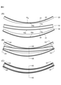
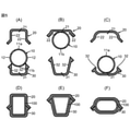
- FIG. 1 It is a schematic diagram for demonstrating an example of the longitudinal shape of a curved tube 10. It is a schematic diagram for demonstrating an example of the longitudinal shape of a hollow member 100. It is a schematic diagram for demonstrating an example of the cross-sectional shape of a curved pipe 10 and the cross-sectional shape of a hollow member 100.
- A) is the cross section of IIIA-IIIA in FIG. 1
- B) is the cross section of IIIB-IIIB in FIG. 1
- C is the cross section of IIIC-IIIC in FIG. 1
- (D) is the cross section of IIID in FIG. -IIID arrow cross section
- E shows the shape of the IIIE-IIIE arrow cross section of FIG.
- FIG. 2 schematically shows the shape of the IIIF-IIIF arrow cross section of FIG.
- FIG. 2 It is a schematic diagram for demonstrating an example of the process of pressing a curved tube 10 to obtain a hollow member 100.
- the shape of the cross section along the longitudinal direction of the pipe is shown.
- (A) is a state before the curved tube 10 is brought into contact with the dies 20 and 30,
- (B) is a state immediately after the curved tube 10 is brought into contact with the dies 20 and 30, and
- (C) is a press working completion. It is the later state.
- (A) is a VA-VA arrow cross section of FIG.
- FIG. 4 (B) is a VB-VB arrow cross section of FIG. 4 (B), and (C) is a VC-VC arrow cross section of FIG. 4 (B).
- (D) is the VD-VD arrow cross section of FIG. 4 (C)
- (E) is the VE-VE arrow cross section of FIG. 4 (C)
- (F) is the VF-VF arrow cross section of FIG. 4 (C).
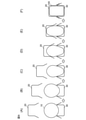
- the shape of the cross section is shown. It is a schematic diagram for demonstrating an example of the flow form in the circumferential direction of a pipe with respect to a press die in press working. It is a schematic diagram for demonstrating an example of the shape of a press die having an inclination.
- FIG. 8 It is a schematic diagram for demonstrating an example of the shape of a raw tube 1.
- A shows the shape in the longitudinal direction
- B shows the shape of the cross section of VIIIB-VIIIB in FIG. 8 (A).
- pressure is applied to the curved tube 10 having the curved portion 10a from the outside of the tube to the inside of the tube by using the press dies 20 and 30.
- This includes simultaneously performing cross-sectional processing of the curved portion 10a and bending processing to reduce the bending radius of the curved portion 10a.
- the curved tube 10 has a curved portion 10a at least in a part thereof.
- the "curved portion” means a bent portion in the longitudinal shape of the pipe.
- the "curved tube” may have a shape that satisfies the relationship of R ⁇ 250D from the bending R at the curved portion and the tube diameter D, for example.
- the curved tube 10 may be bent two-dimensionally or three-dimensionally at the curved portion 10a.
- FIG. 1 shows a form in which the curved tube 10 is bent in the vertical direction of the paper surface at the curved portion 10a, but the curved portion 10a may be further bent in the front direction of the paper surface.
- the bending shape of the curved portion 10a is not particularly limited.
- the curved tube 10 may be curved at the curved portion 10a. It is preferable that the curved tube 10 does not substantially have a discontinuity such as wrinkles or buckling in the curved portion 10a.
- the bending radius R 10 (inner bending radius) in the curved portion 10a is not particularly limited, and may be larger than the bending radius R 100 described later.
- the bending radius R 10 can be appropriately determined in consideration of the material, wall thickness and opening diameter (circle equivalent diameter) of the curved tube 10, the bending radius R 100 and the like described later.
- the bending shape (ridge line) in the longitudinal direction of the curved portion 10a may be composed of only one arc, or may be composed of a combination of a plurality of arcs. Further, in the curved portion 10a, the curvature may change continuously or discontinuously from one end in the longitudinal direction to the other end.
- the bent tube 10 showed a form having only one curved portion 10a
- the bent tube 10 radius R 10 bend may have the same or a different curved portions 10a.
- the press processing described later is performed on each of the plurality of curved portions 10a
- the press processing may be performed simultaneously by one die, or the press processing may be performed separately by a plurality of dies.
- the curved pipe 10 may have a straight pipe portion other than the curved portion 10a.
- the "straight pipe portion” refers to a straight portion having substantially no bending in the longitudinal shape of the pipe.
- the curved tube 10 may be composed of only one or a plurality of curved portions 10a.
- the curved tube 10 does not have to be completely tubular as a whole.
- the curved tube 10 may have a notch, a slit, a through hole, an intentional unevenness, or the like, depending on the intended use. These notches, slits, through holes, irregularities, etc. provided in the curved pipe 10 may remain in the hollow member 100.
- the cross-sectional shape of the curved portion 10a may be an annular shape without interruption.
- the length of the curved tube 10 is not particularly limited and may be appropriately determined depending on the intended use. However, if the length of the curved tube 10 is extremely short, it may be difficult to perform a further bending step described later. In the curved pipe 10, the length from one end to the other end in the longitudinal direction of the pipe (the length of the line continuously connecting the center of the opening (center of the figure)) L 10 rather than the opening diameter (diameter equivalent to a circle) D 10. It may be longer.
- the cross-sectional shape (opening shape) of the curved pipe 10 is not particularly limited.
- 3 (A), (B) and (C) show that the curved tube 10 has a circular cross-sectional shape, but in addition to the circular shape, it has an elliptical shape, a flat circular shape, a polygonal shape, and a rounded shape. There can be various shapes such as a polygonal shape and a combination of these shapes.
- the cross-sectional shape of the curved tube 10 can be appropriately determined in consideration of insertability into the press dies 20 and 30 and the like.
- the cross-sectional shape of the curved pipe 10 may be the same shape without change from one end in the longitudinal direction of the pipe to the other end, or may be continuously or discontinuously changed from one end in the longitudinal direction of the pipe to the other end. You may.
- the curved pipe 10 has a straight pipe portion together with the curved portion 10a
- the curved portion 10a and the straight pipe portion may have the same cross-sectional shape or may have different cross-sectional shapes.
- each curved portion 10a may have the same cross-sectional shape or may have a different cross-sectional shape.
- the thickness (thickness) of the curved tube 10 is not particularly limited and may be appropriately determined depending on the intended use.
- the thickness of the curved tube 10 may be different for each portion.
- the material of the curved tube 10 may be any material that can be pressed, and can be appropriately determined according to the intended use.
- it may be made of a metal such as steel, iron, aluminum, titanium, or magnesium.
- the manufacturing method of the present disclosure is a high-strength steel pipe made of high-strength steel having a tensile strength of 440 MPa or more and 590 MPa or more or 780 MPa or more measured at room temperature in accordance with JIS Z 2241: 2011, or a high-strength steel pipe having a tensile strength of 980 MPa or more. It is also applicable to high-strength steel pipes made of the above ultra-high-strength steel.
- a curved tube 10 having a curved portion 10a may be obtained by at least bending a starting material tube 1 as shown in FIGS. 8A and 8B. Further, the bent tube 10 having the curved portion 10a may be obtained by performing at least bending processing and cross-sectional processing on the raw tube 1.
- the shape of the raw tube 1 is not particularly limited.
- the raw pipe 1 may be a straight pipe.
- the raw pipe 1 may have a curved portion having a bending radius larger than that of the curved portion 10a of the curved pipe 10.
- the raw pipe 1 may have both a curved portion and a straight pipe portion.
- the cross-sectional shape of the raw tube 1 is not particularly limited, and in addition to the circular shape as shown in FIG. 8 (B), an elliptical shape, a flat circular shape, a polygonal shape, a rounded polygonal shape, and these shapes There can be various shapes such as combinations.
- the cross-sectional shape of the raw pipe 1 may be the same shape without change from one end in the longitudinal direction of the pipe toward the other end, or may be continuously or discontinuously changed from one end in the longitudinal direction of the pipe toward the other end. You may.
- the bending method of the raw pipe 1 is not particularly limited.
- the curved pipe 10 may be obtained by pressing the raw pipe 1 from the outside of the pipe. That is, the bending process applied to the raw tube 1 may include applying pressure from the outside of the tube toward the inside of the tube to obtain the curved tube 10 by using a press die.
- the raw pipe 1 may be cross-sectioned using a press die. That is, the bending process and the cross-section process performed on the raw tube 1 may include applying pressure from the outside of the tube toward the inside of the tube to obtain the curved tube 10 by using a press die.
- the bending radius of the press surface for forming the curved portion of the first die is larger than that of the second die. In this way, it is possible to perform the press working from the raw pipe 1 to the curved pipe 10 and the press working from the bent pipe 10 to the hollow member 100 by using the same press processing machine only by replacing the mold. That is, the manufacturing equipment of the curved pipe 10 and the manufacturing equipment of the hollow member 100 can be shared to improve the productivity.
- the curved tube 10 may be obtained by applying pressure to the raw tube 1 from the outside of the tube toward the inside of the tube using a press die and performing bending and cross-section processing at the same time. As a result, the shape accuracy when the curved tube 10 is used is further improved.
- the minimum amount of buckling or wrinkling does not occur by experiments, FEM analysis, etc. in advance before actually bending the raw pipe 1.
- the bending radius (R 10 min ) may be confirmed. That is, when performing the bending base tube 1, by performing the bending process so that the radius R 10 radius R 10min or more bending bending minimum confirmed in advance, the occurrence of buckling or wrinkles in bent tube 10 It can be further suppressed.
- the method for obtaining the curved tube 10 is not limited to the above-mentioned press working method from the outside of the tube using the press die.
- the curved pipe 10 may be obtained by subjecting conventionally known bending processes such as rotary pull bending (pipe bender), tensile bending, pressing bending, push-through bending, and roll bending.
- rotary pull bending pipe bender
- tensile bending pressing bending
- push-through bending push-through bending
- roll bending it is preferable to obtain the curved pipe 10 from the raw pipe 1 by a press working method from the outside of the pipe using a press die.
- the press die may be any as long as it can simultaneously perform cross-sectional processing of the curved portion 10a and bending processing to reduce the bending radius of the curved portion 10a.
- the material of the press die is not particularly limited, and a general material can be used as the die.
- the press die may be composed of a plurality of dies, and in this case, pressure is applied from the outside of the curved tube 10 toward the inside of the tube by relatively moving the plurality of dies. Can be done.
- the press die may have an upper die 20 and a lower die 30. In this case, it is assumed that each of the upper die 20 and the lower die 30 has press surfaces 20a and 30a.
- the curved pipe 10 is pressed from above and below by the upper mold 20 and the lower mold 30, and the pressed surface 20a is pressed against the curved portion 10a of the curved pipe 10.
- pressing 30a cross-section processing and bending processing can be performed at the same time.
- the shape of the press die corresponds to the shape of the hollow member 100.
- the upper die 20 is The lower mold 30 may have a bottom portion 21 facing the upper end portion 11a of the curved pipe 10 and a side wall portion 22 facing the side portion 12 of the curved pipe 10, and the lower mold 30 has a lower end portion 11b of the curved pipe 10. It may have a bottom portion 31 facing the surface and a side wall portion 32 facing the side portion 12 of the curved tube 10, as shown in FIGS. 5 (D) to 5 (F) and FIG. 6 (F). With the upper mold 20 and the lower mold 30 closed, the entire circumference of the hollow member 100 may be surrounded by the bottom portions 21, 31 and the side wall portions 22, 32.
- the inner wall surface of the press die is pressed against the outer wall surface of the hollow member 100 in the cross section orthogonal to the longitudinal direction of the hollow member 100. May have an inclination and a gap may be formed between the outer wall surface of the hollow member 100 and the inner wall surface of the press die.
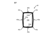
- a part of the inner wall of the press die may have a portion that is convex outward with respect to the outer wall of the hollow member 100. As shown in FIG.
- the cross-sectional processing and bending processing by the press die 40 are completed and the entire circumference of the hollow member 100 is surrounded by the inner wall of the press die 40.
- the inner wall of the press mold 40 may have a portion 40a that is convex outward with respect to the outer wall of the side portion 100y of the hollow member 100, with respect to the outer wall of the bottom portion 100z of the hollow member 100.
- the inner wall surface of the press die is inclined with respect to the outer wall surface of the hollow member 100 in the cross section orthogonal to the longitudinal direction of the hollow member 100, and the hollow member 100 A gap is created between the outer wall surface and the inner wall surface of the press die.
- the inner wall surface of the press die is inclined with respect to the outer wall surface of the hollow member 100, and the outer wall surface of the hollow member 100 and the inner wall surface of the press die are formed.
- the bending radius R M of the press surface of the press die may be smaller than the bending radius R 100 of the curved portion 100a of the hollow member 100.
- the curved tube 20 and the lower mold 30 each have a curved tube 10.
- the 10 is brought into contact with the lower mold 30
- At least one portion other than one end and the other end may be brought into contact with the upper mold 20.
- the pressing direction by the press die is not limited to the vertical direction as shown in FIGS. 4A to 4C, and may be, for example, a horizontal direction. However, in consideration of workability, productivity, etc., the pressing direction by the press die may be the vertical direction.
- a known press machine may be used as the press machine on which the press die is installed.
- cross-sectional processing is performed to change the cross-sectional shape of the curved portion 10a of the curved pipe 10 by applying pressure from the outside of the pipe to the inside of the pipe using the press dies 20 and 30. .. That is, by pressing the press surfaces 20a and 30a of the press dies 20 and 30 against the curved portion 10a from the outside, a material flow is generated in the curved portion 10a in the circumferential direction of the pipe, and the cross-sectional shape of the curved portion 10a is formed. Change. For example, as shown in FIGS.
- the cross-sectional shape of the curved portion 10a is changed from the first shape (for example, a circular shape) to the second shape (for example, an ellipse) by cross-sectional processing. It may be changed to a shape, a polygonal shape, a rounded polygonal shape, or a combination of these shapes).
- pressure is applied from the outside of the pipe to the inside of the pipe. That is, in the manufacturing method of the present disclosure, pressure is not applied from the inside of the pipe to the outside of the pipe as in hydroforming, and the cross-sectional shape of the curved portion 10a of the curved pipe 10 is obtained only by press working from the outside of the pipe. Change.
- a core mold or the like may be installed inside the pipe, for example, at the end of the pipe. This makes it possible to further suppress dents and crushes at the end of the pipe and the like.
- a gap may be formed between the outer wall of the hollow member 100 and the press die in the cross section orthogonal to the longitudinal direction of the hollow member 100, and no gap is generated. You may.
- the cross-sectional processing of the portion other than the portion to be bent to become the curved portion 100a is optional.
- the straight pipe portion may or may not be cross-sectional processed.
- the straight pipe portion is cross-sectioned, the curved portion 10a and the straight pipe portion may be cross-sectioned differently.
- the curved tube 10 has a plurality of curved portions 10a, one curved portion 10a and another curved portion 10a may be subjected to the same cross-sectional processing or different cross-sectional processing.
- Pressure is applied from the outside of the pipe to the inside of the pipe even in bending. That is, in the manufacturing method of the present disclosure, pressure is not applied from the inside of the pipe to the outside of the pipe as in hydroforming, and the bending radius of the curved portion 10a of the curved pipe 10 is obtained only by press working from the outside of the pipe. Make it smaller.
- a gap may or may not be generated between the outer wall of the hollow member 100 and the press die in the longitudinal direction of the hollow member 100.
- bending is optional for parts other than the curved portion 10a.
- the straight pipe portion may be gently bent as long as wrinkles and buckling do not occur.
- the above bending process is performed at the same time as the above cross section process. That is, during press working, the hollow member 100 ensures high shape accuracy by simultaneously advancing the material flow in the circumferential direction and the material flow in the longitudinal direction in the curved portion 10a of the curved tube 10.
- the cross-section processing and bending processing of the pipe using the press die are performed, for example, in the flow as shown in FIGS. 6A to 6F.
- the morphology shown in FIGS. 6 (A) to 6 (F) corresponds to the morphology shown in FIGS. 5 (A) and 5 (D), and the circular pipe cross section is changed to a rounded rectangular cross section. It shows the case of changing. As shown in FIGS.
- the pipe is brought into contact with at least one of the upper mold 20 and the lower mold 30 (FIG. 6A), and the upper mold 20 and the lower mold 30 are brought into contact with each other.
- the upper mold 20 and the lower mold 30 are brought close to each other, and a part of the pipe is inserted while flowing inside the upper mold 20 and the lower mold 30, and molding proceeds without biting the pipe in the gap between the upper mold 20 and the lower mold 30.
- FIGGS. 6 (B) to 6 (E) the cross-sectional processing and bending processing of the pipe can be completed by closing the upper mold 20 and the lower mold 30 (FIG. 6 (F)).
- the cross-section processing and the bending processing proceed at the same time at a certain point in time, and the timing of the start and completion of the cross-section processing and the timing of the start and completion of the bending processing are defined. It does not have to be exactly simultaneous.
- the minimum bending radius (R 100 min ) may be confirmed. That is, when the curved pipe 10 is pressed, buckling and wrinkles are generated in the hollow member 100 by performing the bending process so as to have a bending radius R 100 having a bending radius R 100 min or more, which is the minimum bending radius confirmed in advance. It can be further suppressed.
- the hollow member 100 has a curved portion 100a at least in a part thereof.
- the hollow member 100 may be expressed as a "press-formed tube" because the tube is stamped.
- the longitudinal direction of the hollow member 100 may correspond to the longitudinal direction of the pipe before press working.
- the hollow member 100 may be bent two-dimensionally or three-dimensionally at the curved portion 100a.
- the hollow member 100 is bent in the vertical direction of the paper surface at the curved portion 100a, but the hollow member 100 may be further bent in the front direction of the paper surface at the curved portion 100a.
- the bending shape of the curved portion 100a is not particularly limited.
- the hollow member 100 may be curved at the curved portion 100a.
- the bending radius R 100 (inner bending radius) in the curved portion 100a is not particularly limited, and may be smaller than the above-mentioned bending radius R 10.
- the bending shape (ridge line) in the longitudinal direction of the curved portion 100a may be composed of only one arc, or may be composed of a combination of a plurality of arcs. Further, in the curved portion 100a, the curvature may change continuously or discontinuously from one end in the longitudinal direction to the other end.
- the hollow member 100 showed a form having only one curved portion 100a, the hollow member 100 may be a radius R 100 bend have the same or different bending portion 100a.
- the hollow member 100 may have a straight pipe portion in addition to the curved portion 100a.
- the hollow member 100 may be composed of only one or a plurality of curved portions 100a.
- the hollow member 100 does not have to be completely tubular as a whole.
- the hollow member 100 may have a notch or a slit in a part thereof.
- the hollow member 100 may have a through hole or intentional unevenness in a part thereof.
- the length of the hollow member 100 is not particularly limited and may be appropriately determined depending on the intended use.
- the length of the hollow member 100 may be the same as or different from the length of the curved tube 10.
- the length of the hollow member 100 is larger than the length of the curved tube 10 by undergoing a step of expanding the opening diameter (diameter equivalent to a circle) with respect to the curved tube 10. It may be shorter.
- the length of the hollow member 100 may be longer than the length of the curved pipe 10 by reducing the thickness of the curved pipe 10 or reducing the diameter of the pipe.
- the cross-sectional shape (opening shape) of the hollow member 100 is not particularly limited.
- FIGS. 3 (D), (E), and (F) show that the hollow member 100 has a polygonal or elliptical cross-sectional shape, but in addition to these, a circular shape, a flat circular shape, and a rounded polygon. There can be various shapes such as shapes and combinations of these shapes.
- the cross-sectional shape of the hollow member 100 can be appropriately determined according to its application. By changing the shape of the press surface of the press dies 20 and 30 described above, the cross-sectional shape of the hollow member 100 can be easily changed.
- the cross-sectional shape of the hollow member 100 may be the same shape without change from one end in the longitudinal direction of the pipe toward the other end, or may be the same shape from one end in the longitudinal direction of the pipe as shown in FIGS. 3 (D) to 3 (F). It may change continuously or discontinuously toward the edge. Further, when the hollow member 100 has a straight pipe portion together with the curved portion 100a, the curved portion 100a and the straight pipe portion may have the same cross-sectional shape or may have different cross-sectional shapes. Further, when the hollow member 100 has a plurality of curved portions 100a, the curved portions 100a may have the same cross-sectional shape or may have different cross-sectional shapes.
- the thickness (thickness) of the hollow member 100 is not particularly limited and may be appropriately determined depending on the intended use. The thickness of the hollow member 100 may be different for each portion.
- the curved pipe 10 having the curved portion 10a is press-processed, and the curved portion 10a is cross-sectionally processed while the bending radius of the curved portion 10a is applied. To make it smaller. As a result, molding defects in the curved portion 100a can be suppressed as compared with the case where the hollow member 100 having the curved portion 100a is obtained by pressing from the straight pipe in one step.
- the manufacturing method of the present disclosure is also applicable to, for example, manufacturing a tapered tube. That is, the tapered tube as the hollow member 100 may be obtained by cross-sectional processing by the manufacturing method of the present disclosure, or the tapered tube may be used as the curved tube 10 for obtaining the hollow member 100.
- Example of use of hollow member The use of the hollow member 100 obtained by the manufacturing method of the present disclosure is wide-ranging.
- automobile parts such as bumper beams, suspension members, side rails, trailing arms, upper arms, pillars, torsion beams, door impact beams, and instrument panel beams.
- the method of the present disclosure bending and cross-sectional processing are simultaneously performed on a pre-bent curved tube 10 using a press mold, and the cross-sectional shape of the curved portion 10a of the curved tube 10 is performed.
- the method of the present disclosure may include a step of preparing a curved tube 10 in advance as a step different from the above-mentioned bending process and cross-section processing using a press die. For example, as shown in FIG.
- the raw tube 1 (which may be a straight tube as described above) is at least bent (pre-bent) to obtain a curved tube 10 having a curved portion 10a.
- the obtained curved tube 10 is placed inside the press die from the outside of the press die, and subsequently, the above-mentioned bending process and cross-section process are performed at the same time to form the curved portion 10a of the curved tube 10.
- a hollow member 100 having a predetermined curved portion 100a may be obtained by reducing the bending radius of the curved portion 10a while changing the cross-sectional shape (main molding).
- a curved tube having a small bending radius while suppressing wrinkles and buckling As in the method of the present disclosure, by simultaneously performing bending and cross-section processing on a pre-bent curved tube 10 using a press die, a curved tube having a small bending radius while suppressing wrinkles and buckling.
- the hollow member 100 having the portion 100a can be manufactured.
- Example 2 As shown in FIG. 12, a straight pipe similar to the comparative example is bent (pre-bent) using a press die to obtain a curved pipe having a bending radius of 700 mm, and then the bending is performed. This molding was performed by simultaneously performing cross-section processing and bending processing on the pipe using a press die, and the bending radius of the curved portion was reduced to 570 mm. No wrinkles or buckling were observed in the curved portion of the obtained hollow member.
- the above-mentioned wrinkles and buckling are suppressed by simultaneously performing bending and cross-section processing by press working on a pre-bent curved pipe instead of a straight pipe.
- the method of the present disclosure divides the bending process into, for example, obtaining a curved pipe from a raw pipe and further performing bending and cross-section processing on the curved pipe.
- the deformation is dispersed to the part different from the part bent in the previous step in the bending in the post-process. It is thought that it can be made to do. That is, it is considered that buckling and wrinkling in the finally obtained hollow member can be suppressed by dispersing the deformed portions during the bending process.
Landscapes
- Engineering & Computer Science (AREA)
- Mechanical Engineering (AREA)
- Bending Of Plates, Rods, And Pipes (AREA)
- Shaping Metal By Deep-Drawing, Or The Like (AREA)
Abstract
Description
曲部を有する曲管に対して、プレス金型を用いて管外側から管内側に向かって圧力を付与することで、前記曲部の断面加工と前記曲部の曲げ半径を小さくする曲げ加工とを同時に施すこと、
を含む、中空部材の製造方法
を開示する。
前記プレス金型が上金型と下金型とを有してもよく、
前記上金型及び前記下金型の各々がプレス面を有してもよく、
前記上金型と前記下金型とで前記曲管を上下からプレスして、前記曲管の前記曲部に対して前記プレス面を押し付けることで、前記断面加工と前記曲げ加工とを同時に施してもよい。
素管に対して、少なくとも曲げ加工を施すことで、前記曲部を有する前記曲管を得ること、
を含んでいてもよい。
素管に対して、少なくとも曲げ加工と断面加工とを施すことで、前記曲部を有する前記曲管を得ること、
を含んでいてもよい。
プレス金型を用いて管外側から管内側に向かって圧力を付与して前記曲管を得ること、
を含んでいてもよい。
プレス金型を用いて管外側から管内側に向かって圧力を付与して前記曲管を得ること、
を含んでいてもよい。
1.1 曲管の長手形状
図1に示されるように、曲管10は少なくとも一部に曲部10aを有する。「曲部」とは管長手形状において曲がった部分をいう。本願において、「曲管」とは、例えば、曲部における曲げRと管直径Dとから、R≦250Dなる関係を満たす形状を有するものであってよい。曲管10は曲部10aにおいて2次元的に曲がっていてもよいし、3次元的に曲がっていてもよい。図1には、曲管10が曲部10aにおいて紙面上下方向に曲がった形態を示したが、当該曲部10aにおいてさらに紙面奥手前方向に曲がっていてもよい。曲部10aにおける曲げ形状は特に限定されるものではない。例えば、曲管10は曲部10aにおいて湾曲していてもよい。尚、曲管10は曲部10aにおいて皺や座屈といった不連続面を実質的に有しないほうがよい。
曲管10の断面形状(開口形状)は特に限定されるものではない。図3(A)、(B)及び(C)には曲管10の断面形状が円形状のものを示したが、円形状の他、楕円形状、偏平円形状、多角形状、丸みを帯びた多角形状、これら形状の組み合わせ等、種々の形状があり得る。曲管10の断面形状は、プレス金型20、30への挿入性等を考慮して適宜決定され得る。
曲管10の材質は、プレス加工が可能な材質であればよく、用途に応じて適宜決定され得る。例えば、鋼、鉄、アルミニウム、チタン、マグネシウム等の金属製としてもよい。本開示の製造方法は、JIS Z 2241:2011に準拠して室温で測定される引張強さが440MPa以上、590MPa以上又は780MPa以上の高張力鋼からなる高強度鋼管や、当該引張強さが980MPa以上の超高張力鋼からなる高強度鋼管に対しても適用可能である。
曲管10を得る方法は特に限定されるものではない。例えば、図8(A)及び(B)に示されるような素管(starting material tube)1に対して、少なくとも曲げ加工を施すことで、曲部10aを有する曲管10を得てもよい。また、素管1に対して、少なくとも曲げ加工と断面加工とを施すことで、曲部10aを有する曲管10を得てもよい。
プレス金型は、曲部10aの断面加工と曲部10aの曲げ半径を小さくする曲げ加工とを同時に施すことが可能なものであればよい。プレス金型の材質は特に限定されるものではなく、金型として一般的な材質を採用可能である。プレス金型は複数の金型により構成されていてもよく、この場合、当該複数の金型を相対的に移動させることで、曲管10の管外側から管内側に向かって圧力を付与することができる。例えば、図4(A)に示されるように、プレス金型は、上金型20と下金型30とを有していてもよい。この場合、上金型20及び下金型30の各々がプレス面20a、30aを有するものとする。図4(B)及び(C)に示されるように、上金型20と下金型30とで曲管10を上下からプレスして、曲管10の曲部10aに対してプレス面20a、30aを押し付けることで、断面加工と曲げ加工とを同時に施すことができる。
本開示の製造方法においては、プレス金型20、30を用いて管外側から管内側へと圧力を付与することにより、曲管10の曲部10aの断面形状を変化させる断面加工を施す。すなわち、プレス金型20、30のプレス面20a、30aを曲部10aに対して外側から押し付けることで、曲部10aにおいて管の周方向への材料流動を生じさせ、曲部10aの断面形状を変化させる。例えば、図5(A)~(F)に示されるように、断面加工によって、曲部10aの断面形状を、第1の形状(例えば、円形状等)から、第2の形状(例えば、楕円形状、多角形状、丸みを帯びた多角形状、又は、これら形状の組み合わせ等)へと変化させてもよい。
本開示の製造方法においては、プレス加工により、曲管10の曲部10aの曲げ半径R10を小さくする曲げ加工を施す。すなわち、プレス金型20、30のプレス面20a、30aを曲部10aに対して管外側から押し付けることで、曲部10aにおいて管の長手方向への材料流動を生じさせ、曲部10aの曲げ半径R10を小さくする。例えば、図1及び2に示されるように、曲げ加工によって、曲げ半径R10の曲部10aを、曲げ半径R100の曲部100aへと変化させる。
5.1 中空部材の長手形状
図2に示されるように、中空部材100は少なくとも一部に曲部100aを有する。上述の通り、中空部材100は、管がプレス加工されてなるものであることから、「加工管(press-formed tube)」と表現されるものであってもよい。中空部材100の長手方向は、プレス加工前の管の長手方向と対応し得る。中空部材100は曲部100aにおいて2次元的に曲げられていてもよいし、3次元的に曲げられていてもよい。例えば、図2においては、中空部材100が曲部100aにおいて紙面上下方向に曲げられた形態を示したが、当該曲部100aにおいてさらに紙面奥手前方向に曲げられていてもよい。曲部100aにおける曲げ形状は特に限定されるものではない。例えば、中空部材100は曲部100aにおいて湾曲していてもよい。上述したプレス金型20、30のプレス面の形状を変更することで、中空部材100の曲げ形状を容易に変更できる。
中空部材100の断面形状(開口形状)は、特に限定されるものではない。図3(D)、(E)及び(F)には中空部材100の断面形状が多角形状又は楕円形状のものを示したが、これらの他、円形状、偏平円形状、丸みを帯びた多角形状、これら形状の組み合わせ等、種々の形状があり得る。中空部材100の断面形状は、その用途に応じて適宜決定され得る。上述したプレス金型20、30のプレス面の形状を変更することで、中空部材100の断面形状を容易に変更できる。
本開示の製造方法により得られる中空部材100の用途は多岐に亘る。例えば、バンパービーム、サスペンションメンバー、サイドレール、トレーリングアーム、アッパーアーム、ピラー、トーションビーム、ドアインパクトビーム、インストルメントパネルビーム等の自動車の部品等である。
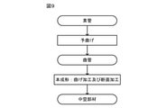
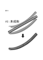
以上の通り、本開示の方法は、予め曲げられた曲管10に対して、プレス金型を用いて曲げ加工と断面加工とを同時に施して、当該曲管10の曲部10aの断面形状を変化させつつ当該曲部10aの曲げ半径を小さくすることで、曲げ半径の小さな曲部100aを有する中空部材100を製造するものである。上述したように、本開示の方法は、上記のプレス金型を用いた曲げ加工及び断面加工とは別の工程として、事前に曲管10を準備する工程を備えるものであってもよい。例えば、図9に示されるように、素管1(上述の通り、直管であってもよい)に対して少なくとも曲げ加工(予曲げ)を施すことで曲部10aを有する曲管10を得てもよい。その後、得られた曲管10を、プレス金型の外部からプレス金型の内部に配置し、続いて、上記の曲げ加工と断面加工とを同時に施して、当該曲管10の曲部10aの断面形状を変化させつつ、当該曲部10aの曲げ半径を小さくすること(本成形)で、所定の曲部100aを有する中空部材100を得てもよい。本開示の方法のように、予め曲げられた曲管10に対してプレス金型を用いて曲げ加工と断面加工とを同時に施すことで、皺や座屈を抑制しつつ、曲げ半径の小さな曲部100aを有する中空部材100を製造できる。
図10に示されるように、直管(980MPa級鋼管、φ38.1mm、厚み1.0mm、長さ600mm)に対してプレス金型を用いて断面加工と曲げ加工とを同時に施して、直管の断面形状を変化させつつ所定の曲げ半径で湾曲させることで、1工程の本成形のみで中空部材を得た。
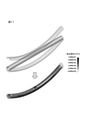
図12に示されるように、比較例と同様の直管に対してプレス金型を用いて曲げ加工(予曲げ)を施すことで、曲げ半径700mmの湾曲管を得た後、当該湾曲管に対してプレス金型を用いて断面加工と曲げ加工とを同時に施す本成形を行い、湾曲部の曲げ半径を570mmにまで小さくした。得られた中空部材の曲部に皺や座屈は認められなかった。
尚、比較例のように、直管に対してプレス加工を1度のみ施して、1工程で、曲げ半径の小さな曲部を有する中空部材を得る場合に、当該中空部材の曲部に皺や座屈といった成形不良が発生してしまう理由については、以下の通りと考えられる。すなわち、直管に対してプレス金型を用いて曲げ加工と断面加工とを同時に施そうとしても、プレス金型のプレス面の曲げ半径が小さ過ぎるため、管の長手方向中央部において、管の周方向に材料がうまく流動できずに内側に凹むような座屈変形が生じる(断面加工される前に曲げ加工のみが進行する)ためと考えられる。
10 曲管(bent tube)
10a 曲部
11a 上端部
11b 下端部
12 側部
20 上金型(プレス金型)
21 底部
22 側壁部
30 下金型(プレス金型)
31 底部
32 側壁部
100 中空部材(hollow shell part)
100a 曲部
Claims (8)
- 曲部を有する曲管に対して、プレス金型を用いて管外側から管内側に向かって圧力を付与することで、前記曲部の断面加工と前記曲部の曲げ半径を小さくする曲げ加工とを同時に施すこと、
を含む、中空部材の製造方法。 - 前記プレス金型が上金型と下金型とを有し、
前記上金型及び前記下金型の各々がプレス面を有し、
前記上金型と前記下金型とで前記曲管を上下からプレスして、前記曲管の前記曲部に対して前記プレス面を押し付けることで、前記断面加工と前記曲げ加工とを同時に施す、
請求項1に記載の製造方法。 - 素管に対して、少なくとも曲げ加工を施すことで、前記曲部を有する前記曲管を得ること、
を含む、請求項1又は2に記載の製造方法。 - 素管に対して、少なくとも曲げ加工と断面加工とを施すことで、前記曲部を有する前記曲管を得ること、
を含む、請求項1又は2に記載の製造方法。 - 前記素管に対して施す前記曲げ加工は、
プレス金型を用いて管外側から管内側に向かって圧力を付与して前記曲管を得ること、
を含む、請求項3に記載の製造方法。 - 前記素管に対して施す前記曲げ加工と前記断面加工とは、
プレス金型を用いて管外側から管内側に向かって圧力を付与して前記曲管を得ること、
を含む、請求項4に記載の製造方法。 - 前記素管が直管である、
請求項3~6のいずれか1項に記載の製造方法。 - 前記断面加工及び曲げ加工が終了した時点で、前記中空部材の長手方向と直交する断面において、前記中空部材の外壁面に対して前記プレス金型の内壁面が傾斜を有し、前記中空部材の外壁面と前記プレス金型の内壁面との間に隙間が生じている、
請求項1~7のいずれか1項に記載の製造方法。
Priority Applications (4)
| Application Number | Priority Date | Filing Date | Title |
|---|---|---|---|
| MX2022015473A MX2022015473A (es) | 2020-07-14 | 2021-06-18 | Metodo de fabricacion de pieza de carcasa hueca. |
| JP2022536195A JP7545071B2 (ja) | 2020-07-14 | 2021-06-18 | 中空部材の製造方法 |
| CN202180013803.9A CN115066301A (zh) | 2020-07-14 | 2021-06-18 | 中空部件的制造方法 |
| US17/923,525 US20230182191A1 (en) | 2020-07-14 | 2021-06-18 | Hollow shell part manufacturing method |
Applications Claiming Priority (2)
| Application Number | Priority Date | Filing Date | Title |
|---|---|---|---|
| JP2020120785 | 2020-07-14 | ||
| JP2020-120785 | 2020-07-14 |
Publications (1)
| Publication Number | Publication Date |
|---|---|
| WO2022014262A1 true WO2022014262A1 (ja) | 2022-01-20 |
Family
ID=79555233
Family Applications (1)
| Application Number | Title | Priority Date | Filing Date |
|---|---|---|---|
| PCT/JP2021/023260 WO2022014262A1 (ja) | 2020-07-14 | 2021-06-18 | 中空部材の製造方法 |
Country Status (5)
| Country | Link |
|---|---|
| US (1) | US20230182191A1 (ja) |
| JP (1) | JP7545071B2 (ja) |
| CN (1) | CN115066301A (ja) |
| MX (1) | MX2022015473A (ja) |
| WO (1) | WO2022014262A1 (ja) |
Cited By (1)
| Publication number | Priority date | Publication date | Assignee | Title |
|---|---|---|---|---|
| WO2023136172A1 (ja) * | 2022-01-13 | 2023-07-20 | 日本製鉄株式会社 | 中空部材の製造方法 |
Citations (3)
| Publication number | Priority date | Publication date | Assignee | Title |
|---|---|---|---|---|
| JPS5410265A (en) * | 1977-06-27 | 1979-01-25 | Kawasaki Heavy Ind Ltd | Sintered hard alloy bent pipe and its manufacture |
| WO2006106622A1 (ja) * | 2005-03-30 | 2006-10-12 | Infec Corporation | 金属管の扁平化加工装置及びその扁平化加工方法並びに金属管製品 |
| WO2016052644A1 (ja) * | 2014-10-03 | 2016-04-07 | 新日鐵住金株式会社 | プレス成形品の製造方法、及びプレス成形品 |
Family Cites Families (2)
| Publication number | Priority date | Publication date | Assignee | Title |
|---|---|---|---|---|
| JP3363975B2 (ja) * | 1993-12-24 | 2003-01-08 | 株式会社ユタカ技研 | 扁平断面をもつ湾曲管の成形方法及び成形装置 |
| JP2019181479A (ja) * | 2018-04-03 | 2019-10-24 | 有限会社山口製作所 | 偏平断面パイプの管端部精密加工方法 |
-
2021
- 2021-06-18 US US17/923,525 patent/US20230182191A1/en active Pending
- 2021-06-18 JP JP2022536195A patent/JP7545071B2/ja active Active
- 2021-06-18 MX MX2022015473A patent/MX2022015473A/es unknown
- 2021-06-18 WO PCT/JP2021/023260 patent/WO2022014262A1/ja active Application Filing
- 2021-06-18 CN CN202180013803.9A patent/CN115066301A/zh active Pending
Patent Citations (3)
| Publication number | Priority date | Publication date | Assignee | Title |
|---|---|---|---|---|
| JPS5410265A (en) * | 1977-06-27 | 1979-01-25 | Kawasaki Heavy Ind Ltd | Sintered hard alloy bent pipe and its manufacture |
| WO2006106622A1 (ja) * | 2005-03-30 | 2006-10-12 | Infec Corporation | 金属管の扁平化加工装置及びその扁平化加工方法並びに金属管製品 |
| WO2016052644A1 (ja) * | 2014-10-03 | 2016-04-07 | 新日鐵住金株式会社 | プレス成形品の製造方法、及びプレス成形品 |
Cited By (2)
| Publication number | Priority date | Publication date | Assignee | Title |
|---|---|---|---|---|
| WO2023136172A1 (ja) * | 2022-01-13 | 2023-07-20 | 日本製鉄株式会社 | 中空部材の製造方法 |
| JP7339592B1 (ja) * | 2022-01-13 | 2023-09-06 | 日本製鉄株式会社 | 中空部材の製造方法 |
Also Published As
| Publication number | Publication date |
|---|---|
| MX2022015473A (es) | 2023-01-16 |
| JPWO2022014262A1 (ja) | 2022-01-20 |
| JP7545071B2 (ja) | 2024-09-04 |
| CN115066301A (zh) | 2022-09-16 |
| US20230182191A1 (en) | 2023-06-15 |
Similar Documents
| Publication | Publication Date | Title |
|---|---|---|
| EP0195157B1 (en) | Method of forming box-section frame members | |
| US4148426A (en) | Method and apparatus for manufacturing metal pipe | |
| JP5868891B2 (ja) | 異径管状部品の製造方法 | |
| US10730092B2 (en) | Pressed article manufacturing method and press mold | |
| JP5191613B2 (ja) | 車両用ホイールリムの製造方法 | |
| TWI711498B (zh) | 成形材製造方法及該成形材 | |
| JP5515566B2 (ja) | 曲がり部材成形方法および曲がり部材ならびに曲がり部材製造方法 | |
| WO2022014262A1 (ja) | 中空部材の製造方法 | |
| WO2013153681A1 (ja) | 閉断面構造部品の製造方法及び装置 | |
| WO2013137086A1 (ja) | 保持器の製造方法及び保持器 | |
| JP2011045923A (ja) | 差厚金属板及びその製造方法 | |
| JP2003285117A (ja) | バルジ加工用素管の製造法、バルジ成形品及びその製造法 | |
| RU2601844C2 (ru) | Способ изготовления стальной трубы | |
| JPH08168814A (ja) | Al合金製自動車構造用中空部材の製造方法 | |
| US6766678B1 (en) | Process for deforming a piece of thin-walled metal tube | |
| JP2012152765A (ja) | 閉断面構造部品の製造方法及び装置 | |
| RU2635491C1 (ru) | Способ изготовления тройников (варианты) | |
| JP7364905B2 (ja) | 板金成形品の製造方法、板金成形品の製造装置、及びフランジアップ工具 | |
| JP6187213B2 (ja) | 自動車用ホイールリムの製造方法 | |
| JP7339592B1 (ja) | 中空部材の製造方法 | |
| JP2001300652A (ja) | 金属管の液圧バルジ加工におけるピアシング方法および金型 | |
| RU2528927C1 (ru) | Способ формообразования неравнопроходных тройников из трубной заготовки | |
| JPH08174047A (ja) | 中空押出形材を用いた自動車用構造部材の成形方法 | |
| RU2696120C1 (ru) | Способ изготовления тройника | |
| JP2003220419A (ja) | 成形ロール及び成形方法 |
Legal Events
| Date | Code | Title | Description |
|---|---|---|---|
| 121 | Ep: the epo has been informed by wipo that ep was designated in this application |
Ref document number: 21841652 Country of ref document: EP Kind code of ref document: A1 |
|
| ENP | Entry into the national phase |
Ref document number: 2022536195 Country of ref document: JP Kind code of ref document: A |
|
| WWE | Wipo information: entry into national phase |
Ref document number: 202217068355 Country of ref document: IN |
|
| NENP | Non-entry into the national phase |
Ref country code: DE |
|
| 122 | Ep: pct application non-entry in european phase |
Ref document number: 21841652 Country of ref document: EP Kind code of ref document: A1 |