WO2022014261A1 - 蓄電装置 - Google Patents
蓄電装置 Download PDFInfo
- Publication number
- WO2022014261A1 WO2022014261A1 PCT/JP2021/023253 JP2021023253W WO2022014261A1 WO 2022014261 A1 WO2022014261 A1 WO 2022014261A1 JP 2021023253 W JP2021023253 W JP 2021023253W WO 2022014261 A1 WO2022014261 A1 WO 2022014261A1
- Authority
- WO
- WIPO (PCT)
- Prior art keywords
- bus bar
- power storage
- main body
- wall portion
- storage device
- Prior art date
- Legal status (The legal status is an assumption and is not a legal conclusion. Google has not performed a legal analysis and makes no representation as to the accuracy of the status listed.)
- Ceased
Links
Images





Classifications
-
- H—ELECTRICITY
- H01—ELECTRIC ELEMENTS
- H01M—PROCESSES OR MEANS, e.g. BATTERIES, FOR THE DIRECT CONVERSION OF CHEMICAL ENERGY INTO ELECTRICAL ENERGY
- H01M50/00—Constructional details or processes of manufacture of the non-active parts of electrochemical cells other than fuel cells, e.g. hybrid cells
- H01M50/50—Current conducting connections for cells or batteries
- H01M50/502—Interconnectors for connecting terminals of adjacent batteries; Interconnectors for connecting cells outside a battery casing
- H01M50/514—Methods for interconnecting adjacent batteries or cells
- H01M50/516—Methods for interconnecting adjacent batteries or cells by welding, soldering or brazing
-
- H—ELECTRICITY
- H01—ELECTRIC ELEMENTS
- H01M—PROCESSES OR MEANS, e.g. BATTERIES, FOR THE DIRECT CONVERSION OF CHEMICAL ENERGY INTO ELECTRICAL ENERGY
- H01M50/00—Constructional details or processes of manufacture of the non-active parts of electrochemical cells other than fuel cells, e.g. hybrid cells
- H01M50/50—Current conducting connections for cells or batteries
- H01M50/502—Interconnectors for connecting terminals of adjacent batteries; Interconnectors for connecting cells outside a battery casing
- H01M50/505—Interconnectors for connecting terminals of adjacent batteries; Interconnectors for connecting cells outside a battery casing comprising a single busbar
-
- H—ELECTRICITY
- H01—ELECTRIC ELEMENTS
- H01M—PROCESSES OR MEANS, e.g. BATTERIES, FOR THE DIRECT CONVERSION OF CHEMICAL ENERGY INTO ELECTRICAL ENERGY
- H01M50/00—Constructional details or processes of manufacture of the non-active parts of electrochemical cells other than fuel cells, e.g. hybrid cells
- H01M50/20—Mountings; Secondary casings or frames; Racks, modules or packs; Suspension devices; Shock absorbers; Transport or carrying devices; Holders
- H01M50/204—Racks, modules or packs for multiple batteries or multiple cells
-
- H—ELECTRICITY
- H01—ELECTRIC ELEMENTS
- H01M—PROCESSES OR MEANS, e.g. BATTERIES, FOR THE DIRECT CONVERSION OF CHEMICAL ENERGY INTO ELECTRICAL ENERGY
- H01M50/00—Constructional details or processes of manufacture of the non-active parts of electrochemical cells other than fuel cells, e.g. hybrid cells
- H01M50/20—Mountings; Secondary casings or frames; Racks, modules or packs; Suspension devices; Shock absorbers; Transport or carrying devices; Holders
- H01M50/204—Racks, modules or packs for multiple batteries or multiple cells
- H01M50/207—Racks, modules or packs for multiple batteries or multiple cells characterised by their shape
- H01M50/209—Racks, modules or packs for multiple batteries or multiple cells characterised by their shape adapted for prismatic or rectangular cells
-
- H—ELECTRICITY
- H01—ELECTRIC ELEMENTS
- H01M—PROCESSES OR MEANS, e.g. BATTERIES, FOR THE DIRECT CONVERSION OF CHEMICAL ENERGY INTO ELECTRICAL ENERGY
- H01M50/00—Constructional details or processes of manufacture of the non-active parts of electrochemical cells other than fuel cells, e.g. hybrid cells
- H01M50/50—Current conducting connections for cells or batteries
-
- H—ELECTRICITY
- H01—ELECTRIC ELEMENTS
- H01M—PROCESSES OR MEANS, e.g. BATTERIES, FOR THE DIRECT CONVERSION OF CHEMICAL ENERGY INTO ELECTRICAL ENERGY
- H01M50/00—Constructional details or processes of manufacture of the non-active parts of electrochemical cells other than fuel cells, e.g. hybrid cells
- H01M50/50—Current conducting connections for cells or batteries
- H01M50/502—Interconnectors for connecting terminals of adjacent batteries; Interconnectors for connecting cells outside a battery casing
- H01M50/503—Interconnectors for connecting terminals of adjacent batteries; Interconnectors for connecting cells outside a battery casing characterised by the shape of the interconnectors
-
- H—ELECTRICITY
- H01—ELECTRIC ELEMENTS
- H01M—PROCESSES OR MEANS, e.g. BATTERIES, FOR THE DIRECT CONVERSION OF CHEMICAL ENERGY INTO ELECTRICAL ENERGY
- H01M50/00—Constructional details or processes of manufacture of the non-active parts of electrochemical cells other than fuel cells, e.g. hybrid cells
- H01M50/50—Current conducting connections for cells or batteries
- H01M50/502—Interconnectors for connecting terminals of adjacent batteries; Interconnectors for connecting cells outside a battery casing
- H01M50/507—Interconnectors for connecting terminals of adjacent batteries; Interconnectors for connecting cells outside a battery casing comprising an arrangement of two or more busbars within a container structure, e.g. busbar modules
-
- H—ELECTRICITY
- H01—ELECTRIC ELEMENTS
- H01M—PROCESSES OR MEANS, e.g. BATTERIES, FOR THE DIRECT CONVERSION OF CHEMICAL ENERGY INTO ELECTRICAL ENERGY
- H01M50/00—Constructional details or processes of manufacture of the non-active parts of electrochemical cells other than fuel cells, e.g. hybrid cells
- H01M50/50—Current conducting connections for cells or batteries
- H01M50/502—Interconnectors for connecting terminals of adjacent batteries; Interconnectors for connecting cells outside a battery casing
- H01M50/521—Interconnectors for connecting terminals of adjacent batteries; Interconnectors for connecting cells outside a battery casing characterised by the material
- H01M50/522—Inorganic material
-
- H—ELECTRICITY
- H01—ELECTRIC ELEMENTS
- H01M—PROCESSES OR MEANS, e.g. BATTERIES, FOR THE DIRECT CONVERSION OF CHEMICAL ENERGY INTO ELECTRICAL ENERGY
- H01M50/00—Constructional details or processes of manufacture of the non-active parts of electrochemical cells other than fuel cells, e.g. hybrid cells
- H01M50/50—Current conducting connections for cells or batteries
- H01M50/543—Terminals
- H01M50/547—Terminals characterised by the disposition of the terminals on the cells
- H01M50/55—Terminals characterised by the disposition of the terminals on the cells on the same side of the cell
-
- H—ELECTRICITY
- H01—ELECTRIC ELEMENTS
- H01M—PROCESSES OR MEANS, e.g. BATTERIES, FOR THE DIRECT CONVERSION OF CHEMICAL ENERGY INTO ELECTRICAL ENERGY
- H01M50/00—Constructional details or processes of manufacture of the non-active parts of electrochemical cells other than fuel cells, e.g. hybrid cells
- H01M50/50—Current conducting connections for cells or batteries
- H01M50/543—Terminals
- H01M50/552—Terminals characterised by their shape
- H01M50/553—Terminals adapted for prismatic, pouch or rectangular cells
-
- H—ELECTRICITY
- H01—ELECTRIC ELEMENTS
- H01M—PROCESSES OR MEANS, e.g. BATTERIES, FOR THE DIRECT CONVERSION OF CHEMICAL ENERGY INTO ELECTRICAL ENERGY
- H01M2220/00—Batteries for particular applications
- H01M2220/20—Batteries in motive systems, e.g. vehicle, ship, plane
-
- Y—GENERAL TAGGING OF NEW TECHNOLOGICAL DEVELOPMENTS; GENERAL TAGGING OF CROSS-SECTIONAL TECHNOLOGIES SPANNING OVER SEVERAL SECTIONS OF THE IPC; TECHNICAL SUBJECTS COVERED BY FORMER USPC CROSS-REFERENCE ART COLLECTIONS [XRACs] AND DIGESTS
- Y02—TECHNOLOGIES OR APPLICATIONS FOR MITIGATION OR ADAPTATION AGAINST CLIMATE CHANGE
- Y02E—REDUCTION OF GREENHOUSE GAS [GHG] EMISSIONS, RELATED TO ENERGY GENERATION, TRANSMISSION OR DISTRIBUTION
- Y02E60/00—Enabling technologies; Technologies with a potential or indirect contribution to GHG emissions mitigation
- Y02E60/10—Energy storage using batteries
Definitions
- the present invention relates to a power storage device including a power storage element.
- Patent Document 1 discloses an assembled battery including a plurality of elementary batteries.
- a metal line is joined to the electrode terminals of a plurality of adjacent elementary batteries, whereby the plurality of elementary batteries are connected in series or in parallel. Ultrasonic bonding is used to bond this metal line to the electrode terminals of the elementary battery.
- the present invention has been made by the inventor of the present application with a new focus on the above-mentioned problems, and an object of the present invention is to provide a power storage device having a simple configuration and improved quality.
- the power storage device includes a power storage element having an electrode terminal arranged in the first direction and a bus bar joined to the electrode terminal, and the bus bar is joined to the electrode terminal.
- a bus bar main body having a portion, a first wall portion erected in the first direction from the bus bar main body portion, and at least a part thereof overlap with the bus bar main body portion when viewed from the first direction.
- it has a second wall portion arranged in a posture facing the bus bar main body portion.
- FIG. 1 is a perspective view showing the appearance of the power storage device according to the embodiment.
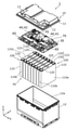
- FIG. 2 is an exploded perspective view of the power storage device according to the embodiment.
- FIG. 3 is a perspective view showing the structural relationship between the bus bar frame, the bus bar, and the electric device according to the embodiment.
- FIG. 4 is a perspective view showing a state in which the power storage element and the electric device according to the embodiment are connected via a bus bar.
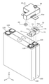
- FIG. 5 is an exploded perspective view corresponding to FIG.
- FIG. 6 is a partially enlarged view showing a method of joining the bus bar and the electrode terminal of the power storage element according to the embodiment.
- FIG. 7 is a partially enlarged view showing the configuration of the bus bar and its surroundings according to the first modification of the embodiment.
- FIG. 8 is a partially enlarged view showing the configuration of the bus bar and its surroundings according to the second modification of the embodiment.
- FIG. 9 is a perspective view showing the appearance of the bus bar according to the third modification of the embodiment.
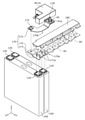
- FIG. 10 is an exploded perspective view showing the connection relationship between the bus bar, the power storage element, and the electric device according to the third modification of the embodiment.
- the power storage device includes a power storage element having an electrode terminal arranged in the first direction and a bus bar joined to the electrode terminal, and the bus bar is joined to the electrode terminal.
- a bus bar main body having a portion, a first wall portion erected in the first direction from the bus bar main body portion, and at least a part thereof overlap with the bus bar main body portion when viewed from the first direction.
- it has a second wall portion arranged in a posture facing the bus bar main body portion.
- the first wall portion functions as a wall that suppresses the scattering of spatter that occurs when the bus bar main body portion and the electrode terminal are joined.
- the second wall portion is arranged directly above the bus bar main body portion, for example, and can be used as a terminal connected to an electric device such as a relay or a control circuit. Therefore, it is possible to obtain the effects of suppressing the path resistance between the electrode terminal and the electric device, or reducing the size of the power storage device.
- the power storage device according to this embodiment is a power storage device having a simple configuration and improved quality.
- the second wall portion is an opening penetrating in the first direction, and has an opening portion arranged at a position where at least a part overlaps with the joint portion when viewed from the first direction. May be.
- the bus bar main body and the electrode terminal can be joined by irradiating the laser beam from the position facing the bus bar main body through the opening. That is, the laser beam can be efficiently irradiated to the bus bar main body through the opening of the second wall, and the scattering of spatter can be suppressed in the portion other than the opening of the second wall. As a result, a highly reliable joint can be efficiently formed.
- the second wall portion may be erected from the end of the first wall portion on the opposite side of the bus bar main body portion in a direction intersecting the first wall portion.
- a bus bar having a configuration in which the bus bar main body portion, the first wall portion, and the second wall portion are connected in this order is realized.
- the effect of reducing the space volume required for arranging the bus bar or further suppressing the path resistance between the electrode terminal and the electric device can be obtained.
- the power storage device may further include an insulating member arranged between the bus bar main body portion and the second wall portion.
- the insulating member functions as a member that suppresses contact between a part of the bus bar and another conductive member. Therefore, the possibility of a short circuit occurring at the time of a collision or the like is reduced.
- bus bar main body portion has a protruding portion that is provided at a position that does not overlap with the second wall portion and protrudes in the second direction that intersects the first direction when viewed from the first direction. good.
- the bus bar main body portion has a protruding portion that protrudes sideways, so that the joining work by laser welding or the like is performed.
- the protruding portion can be used as a holding portion for holding the bus bar main body. As a result, a highly reliable joint can be obtained.
- the bus bar main body may be joined to the electrode terminal of each of the two power storage elements arranged side by side.
- the bus bar functions as a conductive member connected to an electric device such as a relay or a control circuit, and also as a conductive member for connecting at least two energy storage elements arranged side by side in series or in parallel. Also works. This contributes to the suppression of the path resistance, the miniaturization of the power storage device, and the like, and as a result, the quality of the power storage device is improved.
- the longitudinal direction of the exterior body of the power storage device, the arrangement direction of a plurality of power storage elements, or the facing direction of the long side surface of the container of the power storage element is defined as the X-axis direction.
- the short side direction of the exterior body of the power storage device, the opposite direction of the short side surface of the container of the power storage element, or the arrangement direction of the pair of electrode terminals in one power storage element is defined as the Y-axis direction.
- the alignment direction between the main body and the lid of the exterior body of the power storage device, the arrangement direction between the bus bar frame and the power storage element unit, or the vertical direction is defined as the Z-axis direction.
- X-axis directions, Y-axis directions, and Z-axis directions intersect each other (orthogonally in the present embodiment).
- the Z-axis direction may not be the vertical direction, but for convenience of explanation, the Z-axis direction will be described below as the vertical direction.
- the X-axis plus direction indicates the arrow direction of the X-axis
- the X-axis minus direction indicates the direction opposite to the X-axis plus direction.
- the term "X-axis direction" simply means bidirectional or either direction parallel to the X-axis. The same applies to terms relating to the Y-axis and the Z-axis.
- expressions indicating relative directions or postures such as parallel and orthogonal include cases where the direction or posture is not strictly speaking.
- the fact that two directions are orthogonal not only means that the two directions are completely orthogonal, but also that they are substantially orthogonal, that is, a difference of, for example, about several percent. It also means to include.
- FIG. 1 is a perspective view showing the appearance of the power storage device 1 according to the embodiment.
- FIG. 2 is an exploded perspective view of the power storage device 1 according to the embodiment.
- FIG. 3 is a perspective view showing the structural relationship between the bus bar frame 30, the bus bars 60 and 70, and the electric device 40 according to the embodiment.
- FIG. 3 shows a state in which the bus bars 60 and 70 and the electric device 40 are separated from the bus bar frame 30.
- FIG. 3 shows a member such as a bus bar frame 30 in a state of being rotated by 180 ° around the Z axis from the posture shown in FIG.
- a bus bar connecting the electric device 40 and the external terminal 13 is housed, and a spacer arranged along the power storage element 100.
- a restraining member or the like that restrains the plurality of power storage elements 100 may be arranged.
- the illustration and description of these members will be omitted as appropriate.
- the power storage device 1 is a device capable of charging electricity from the outside and discharging electricity to the outside, and has a substantially rectangular parallelepiped shape in the present embodiment.
- the power storage device 1 is, for example, a battery module (assembled battery) used for power storage, power supply, and the like.
- the power storage device 1 is for driving or starting an engine of a moving body such as an automobile, a motorcycle, a watercraft, a ship, a snowmobile, an agricultural machine, a construction machine, or a railroad vehicle for an electric railway. It is used as a battery or the like.
- Examples of the above-mentioned vehicle include an electric vehicle (EV), a hybrid electric vehicle (HEV), a plug-in hybrid electric vehicle (PHEV), and a gasoline vehicle.
- Examples of the above-mentioned railway vehicle for electric railways include trains, monorails, linear motor cars, and hybrid trains including both diesel engines and electric motors.
- the power storage device 1 can also be used as a stationary battery or the like used for home use, a generator, or the like.
- the power storage device 1 includes an exterior body 10, a power storage element unit 50 housed in the exterior body 10, and a bus bar frame 30.
- the exterior body 10 is a box-shaped (substantially rectangular parallelepiped) container (module case) that constitutes the housing of the power storage device 1. That is, the exterior body 10 is arranged outside the power storage element unit 50 and the bus bar frame 30, and these power storage element units 50 and the bus bar frame 30 are fixed at predetermined positions to protect them from impacts and the like.
- the exterior body 10 includes, for example, polycarbonate (PC), polypropylene (PP), polyethylene (PE), polystyrene (PS), polyphenylene sulfide resin (PPS), polyphenylene ether (PPE (including modified PPE)), polyethylene terephthalate (including modified PPE). PET), polybutylene terephthalate (PBT), polyetheretherketone (PEEK), tetrafluoroethylene / perfluoroalkylvinyl ether (PFA), polytetrafluoroethylene (PTFE), polyethersulfon (PES), ABS resin, or , These composite materials and other insulating members, or insulatingly coated metal and the like.
- PC polycarbonate
- PP polypropylene
- PE polyethylene
- PS polystyrene
- PPS polyphenylene sulfide resin
- PPE polyphenylene ether
- PET polybutylene terephthalate
- PEEK polyetheretherketone
- the exterior body 10 prevents the power storage element unit 50 and the like from coming into contact with an external metal member and the like.
- the exterior body 10 may be formed of a conductive member such as metal as long as the electrical insulation between the exterior body 10 and the power storage element unit 50 or the like is maintained.
- the exterior body 10 has an exterior body main body 12 constituting the main body of the exterior body 10 and a lid body 11.
- the exterior body body 12 is a bottomed rectangular tubular housing having an opening 12a formed on the Z-axis plus direction side, and accommodates a power storage element unit 50, a bus bar frame 30, and the like.
- the lid 11 is a rectangular member that closes the opening 12a of the exterior body 12.
- the lid 11 is preferably airtightly or watertightly bonded to the exterior body 12 by an adhesive, heat seal, ultrasonic welding, laser welding, or the like.
- a pair of external terminals 13 which are a pair of module terminals on the positive electrode side and the negative electrode side are arranged on the lid 11.
- the power storage device 1 charges electricity from the outside and discharges electricity to the outside through the pair of external terminals 13.
- the external terminal 13 is formed of, for example, a conductive member made of a metal such as aluminum, an aluminum alloy, copper, or a copper alloy.
- the power storage element unit 50 is an aggregate of power storage elements 100 composed of one or more power storage elements 100.
- the power storage element unit 50 according to the present embodiment is composed of a plurality of power storage elements 100, and the plurality of power storage elements 100 are arranged in the X-axis direction with the long side surface 110a facing the X-axis direction. There is.
- the power storage element unit 50 may have a spacer (not shown) arranged between adjacent power storage elements 100, or may have a restraint member (not shown) that restrains a plurality of power storage elements 100.
- the power storage element 100 is a secondary battery (single battery) capable of charging electricity and discharging electricity, and more specifically, a non-aqueous electrolyte secondary battery such as a lithium ion secondary battery.
- the power storage element 100 has a flat rectangular parallelepiped (square) container 110 and a pair of electrode terminals 120 (positive electrode side and negative electrode side) fixed to the container 110.
- An electrode body, a current collector, an electrolytic solution, and the like are housed inside the container 110.
- Examples of the electrode body included in the power storage element 100 include a wound type electrode body formed by winding a layered electrode body in which a separator is sandwiched between a positive electrode plate and a negative electrode plate.
- the power storage element 100 is provided with a laminated type (stack type) electrode body formed by laminating a plurality of flat plate-shaped electrode plates or a bellows type electrode body obtained by folding the electrode plates into a bellows shape. good.
- laminated type (stack type) electrode body formed by laminating a plurality of flat plate-shaped electrode plates or a bellows type electrode body obtained by folding the electrode plates into a bellows shape. good.
- the power storage element 100 is not limited to the non-aqueous electrolyte secondary battery, and may be a secondary battery other than the non-aqueous electrolyte secondary battery, or may be a capacitor.
- the power storage element 100 may be a primary battery that can use the stored electricity without being charged by the user, instead of the secondary battery.
- the power storage element 100 may be a battery using a solid electrolyte.
- the power storage element 100 may be a pouch-type power storage element.
- the shape of the power storage element 100 is not limited to the above-mentioned square shape, and may be a polygonal pillar shape, a cylindrical shape, an elliptical pillar shape, a long cylindrical shape, or the like.
- the container 110 has a pair of long side surfaces 110a, a pair of short side surfaces 110b, and a terminal arrangement surface 110c.
- the terminal arrangement surface 110c is a surface on which the electrode terminals 120 on the positive electrode side and the negative electrode side are arranged.
- the gas discharge valve 105 is further arranged on the terminal arrangement surface 110c. When the internal pressure of the container 110 rises excessively, the gas discharge valve 105 receives the internal pressure and opens the gas discharge valve 105, whereby the gas inside the container 110 is discharged to the outside.
- the bus bar frame 30 is a flat rectangular insulating member arranged facing the terminal arrangement surface 110c of the power storage element 100 and holding the bus bars 60 and 70 and the electric device 40.
- the bus bar frame 30 is made of, for example, any electrically insulating resin material that can be used for the exterior body 10.
- the bus bar frame 30 has a plurality of bus bar openings 30a for holding a part of each of the bus bars 60 and 70 in a state of being exposed to the power storage element 100 side.
- Each of the bus bars 60 and 70 arranged in the bus bar opening 30a is positioned with respect to the electrode terminal 120 which is a joining partner, and in that state, is joined to the electrode terminal 120 by, for example, laser welding.
- the power storage element unit 50 has eight power storage elements 100. In these eight power storage elements 100, two adjacent power storage elements 100 are connected in parallel by a bus bar 60, whereby four groups of power storage elements 100 connected in parallel are formed. Further, these four power storage element 100 groups are connected in series by three bus bars 60.
- a bus bar 70 is joined to each of the total plus terminal 121 and the total minus terminal 122 of the power storage element unit 50 having eight power storage elements 100 electrically connected in this way.
- the electrode terminals 120 on the positive electrode side of the two power storage elements 100 at the ends in the plus direction of the X axis are the total plus terminals 121, and the end 2 in the minus direction of the X axis.
- the electrode terminal 120 on the negative electrode side of the two power storage elements 100 is a total negative terminal 122.
- the electric device 40 arranged on the bus bar frame 30 is electrically connected to the power storage element unit 50 via the bus bar 70.
- the electric devices 41 and 42 are provided in the power storage device 1 as the electric devices 40 arranged in the bus bar frame 30.
- the electric device 42 is, for example, a control device called a BMU (Battery Management unit), detects the voltage of each of the plurality of power storage elements 100, the temperature of the power storage element unit 50, and the like, and controls the charging state of the plurality of power storage elements 100. ..
- the connection terminal 42a of the electric device 42 is connected to the bus bar 70 with a screw 48, whereby the electric device 42 and the two electrode terminals 120 which are the total negative terminals 122 are electrically and mechanically connected by the bus bar 70. Will be done.
- the electric device 42 is electrically connected to the external terminal 13 on the negative electrode side fixed to the lid 11 of the exterior body 10 via a bus bar (not shown).
- the electric device 41 is, for example, a relay unit having an electromagnetic switch, and has a function of switching on and off of charging or discharging of the power storage device 1.
- the connection terminal 41a of the electric device 41 is connected to the bus bar 70 with a screw 48, whereby the electric device 41 and the two electrode terminals 120 which are the total positive terminals 121 are electrically and mechanically connected by the bus bar 70. Be connected.
- the electric device 41 is electrically connected to the external terminal 13 on the positive electrode side fixed to the lid 11 of the exterior body 10 via a bus bar (not shown).
- the bus bar 70 connecting the electric device 40 and the power storage element unit 50 is three-dimensionally arranged as shown in FIG. 3, a bus bar main body 71 and a first wall portion. It has 72 and a second wall portion 73.
- the configuration of the bus bar 70 having such a characteristic shape and its surroundings will be described below.
- bus bar 70 and its surroundings in the power storage device 1 will be described with reference to FIGS. 4 to 6.
- two bus bars 70 for connecting the power storage element unit 50 and the electric device 40 are provided, and these two bus bars 70 have common features. Therefore, in the following, the bus bar 70 connected to the electric device 41 will be focused on and described, and the illustration and description of the bus bar 70 connected to the electric device 42 will be omitted.
- FIG. 4 is a perspective view showing a state in which the power storage element 100 and the electric device 41 according to the embodiment are connected via the bus bar 70.
- FIG. 4 only the bus bar 70 and the two power storage elements 100 and the electric device 41 connected to the bus bar 70 are shown, and the other members such as the other power storage element 100 and the bus bar frame 30 are not shown.
- FIG. 5 is an exploded perspective view corresponding to FIG.
- FIG. 6 is a partially enlarged view showing a method of joining the bus bar 70 and the electrode terminal 120 of the power storage element 100 according to the embodiment.
- the power storage element 100 has an electrode terminal 120 in the Z-axis plus direction, which is an example of the first direction.
- the electrode terminal 120 and the bus bar 70 are joined at a joint portion 71a formed in the bus bar main body portion 71 of the bus bar 70.
- the joint portion 71a is formed by laser welding in this embodiment.
- the bus bar main body 71 is formed with a through hole through which the bolt is penetrated so that the bus bar main body 71 can be joined to the bolt terminal.
- the bus bar main body 71 is joined to the bolt terminal. It is not necessary to have a through hole for the purpose.
- the bus bar 70 further has a first wall portion 72 erected from the bus bar main body portion 71 in the Z-axis plus direction. That is, the first wall portion 72 exists as a metal shielding wall that partitions the space on the Y-axis plus direction side when viewed from the joint portion 71a. Therefore, even if spatter occurs during laser welding for forming the joint portion 71a, at least the scattering of the spatter on the Y-axis plus direction side of the bus bar 70 is suppressed. Since laser welding is performed in a state where the power storage element unit 50 is housed in the exterior body body 12, the first wall portion 72 is located on the Y-axis plus direction side of the bus bar 70 in the exterior body body 12 and the bus bar frame 30. Damage to the part due to spatter is suppressed.
- the second wall portion 73 is fixed to the first wall portion 72 in a posture facing the bus bar main body portion 71.
- the second wall portion 73 is formed with a mounting hole 73a for connecting to the electrical device 41, and the screw 48 and the nut 49 inserted into the mounting hole 73a through the connection terminal 41a of the electrical device 41.
- the bus bar 70 and the electric device 41 are connected. That is, the electric device 41 is connected to the electrode terminal 120 in a state where the conduction path between the electrode terminal 120 and the electric device terminal 120 is relatively short.
- An opening 74 is further formed in the second wall portion 73. As shown in FIG.
- the opening 74 is used as a hole for passing laser light La in laser welding between the bus bar main body 71 and the electrode terminal 120 of the power storage element 100. That is, since the opening 74 is provided in the second wall 73, the laser beam La can be irradiated to the bus bar 71 from a position opposite to the bus bar 71 across the second wall 73. ..
- the power storage device 1 includes a power storage element 100 having an electrode terminal 120 arranged in the plus direction of the Z axis, and a bus bar 70 joined to the electrode terminal 120.
- the bus bar 70 has a bus bar main body portion 71 having a joint portion 71a joined to the electrode terminal 120, a first wall portion 72, and a second wall portion 73.
- the first wall portion 72 is erected from the bus bar main body portion 71 in the Z-axis plus direction. At least a part of the second wall portion 73 overlaps with the bus bar main body 71 when viewed from the Z-axis plus direction, and is arranged in a posture facing the bus bar main body 71.
- the first wall portion 72 functions as a wall that suppresses scattering of spatter generated when the bus bar main body portion 71 and the electrode terminal 120 are joined.
- the second wall portion 73 is arranged directly above the bus bar main body portion 71 (Z-axis plus direction side), and can be used as a terminal for connecting to the electric device 41. Therefore, the effect of suppressing the path resistance between the electrode terminal 120 and the electric device 41, or reducing the size of the power storage device 1 can be obtained.
- the bus bar 70 is a member that directly connects the power storage element unit 50 and the electric device 40 (41, 42) in the main current path through which the current flows during discharging and charging of the power storage element unit 50. Is. Therefore, since the path resistance in the bus bar 70 is relatively small, for example, the charge / discharge efficiency of the power storage device 1 is improved. As described above, the quality of the power storage device 1 according to this embodiment can be improved with a simple configuration.
- the first wall portion 72 when viewed from the center of the power storage element 100 in the top view, the first wall portion 72 is located on the outside of the joint portion 71a (on the Y-axis plus direction side in FIGS. 4 to 6). However, the first wall portion 72 may be located inside the joint portion 71a (on the Y-axis minus direction side in FIGS. 4 to 6). However, the fact that the first wall portion 72 is located outside the joint portion 71a is advantageous from the viewpoint of protecting the peripheral portion (see FIG. 2) of the opening 12a of the exterior body main body 12.
- the first wall portion 72 when the first wall portion 72 is located outside the joint portion 71a, the first wall portion is located between the portion of the peripheral edge portion of the opening 12a closest to the joint portion 71a and the joint portion 71a. 72 is arranged. Thereby, the first wall portion 72 can protect the peripheral edge portion of the opening 12a before being joined to the lid 11 from the spatter generated during the formation of the joining portion 71a. Therefore, the possibility that the peripheral edge of the opening 12a is deformed or damaged by spatter is reduced. As a result, the lid 11 and the exterior body 12 can be accurately joined by welding or the like.
- the second wall portion 73 is an opening 74 penetrating in the Z-axis plus direction, and is arranged at a position where at least a part overlaps with the joint portion 71a when viewed from the Z-axis plus direction. It has an opening 74 that has been made.
- the joint portion 71a is formed inside the projection region (opening region 74a) on the bus bar main body 71 of the opening in the opening 74. That is, when viewed from the Z-axis plus direction, a part of the opening 74 overlaps with the joint portion 71a.
- the bus bar main body 71 and the electrode terminal 120 can be joined by irradiating the laser beam from the position facing the bus bar main body 71 through the opening 74. That is, the laser beam can be irradiated from a direction parallel to the thickness direction of the bus bar main body 71 (direction perpendicular to the surface of the bus bar main body 71). That is, the laser beam can be efficiently irradiated to the bus bar main body 71 through the opening 74 of the second wall 73. Further, scattering of spatter can be suppressed at a portion other than the opening 74 of the second wall portion 73. As a result, a highly reliable joint portion 71a can be efficiently formed.
- the second wall portion 73 is in the direction intersecting the first wall portion 72 from the end portion (the end portion in the Z-axis plus direction) of the first wall portion 72 opposite to the bus bar main body portion 71. It is erected in.
- the bus bar 70 having a configuration in which the bus bar main body portion 71, the first wall portion 72, and the second wall portion 73 are connected in this order is realized. As a result, the effect of reducing the space volume required for arranging the bus bar 70 or further suppressing the path resistance between the electrode terminal 120 and the electric device 40 can be obtained.
- the bus bar main body 71 is joined to the electrode terminals 120 of each of the two power storage elements 100 arranged side by side, as shown in FIGS. 2 to 6.
- the bus bar 70 functions as a conductive member connected to the electric device 40, and at least two power storage elements 100 arranged side by side are connected in series or in parallel (parallel in the present embodiment). It also functions as a conductive member for connection. This contributes to the suppression of the path resistance, the miniaturization of the power storage device 1, and the like, and as a result, the quality of the power storage device 1 is improved.
- the power storage device 1 may have a configuration different from the configurations shown in FIGS. 4 to 6 with respect to the configuration of the bus bar 70 and its surroundings. Therefore, a modified example of the configuration of the bus bar 70 and its surroundings will be described below, focusing on the difference from the above embodiment.
- FIG. 7 is a partially enlarged view showing the configuration of the bus bar 70 and its surroundings according to the first modification of the embodiment.
- the electric device 40 connected to the bus bar 70 is not shown, and the insulating member 80 is shown by shifting it from its original position in the minus direction of the Y-axis.
- the insulating member 80 is attached to the bus bar 70, and this point is different from the power storage device 1 according to the embodiment.
- the power storage device 1a includes an insulating member 80 arranged between the bus bar main body portion 71 and the second wall portion 73.
- the bus bar main body 71 in the bus bar 70 having a structure that easily receives an external force in the event of a collision or the like by having a wall (first wall portion 72) rising from the bus bar main body 71, the bus bar main body 71 and the second An insulating member 80 is provided between the wall portion 73 and the wall portion 73.
- the insulating member 80 suppresses contact between a part of the bus bar 70 and another conductive member such as the container 110 of the power storage element 100. Functions as a member. Therefore, the possibility of a short circuit occurring at the time of a collision or the like is reduced.
- the insulating member 80 has a nut holding portion 81 for holding the nut 49.
- the nut holding portion 81 is a non-circular recess that covers the outer periphery of the nut 49 having a non-circular outer shape when viewed from the axial direction (Z-axis direction) of the nut 49, and therefore can also serve as a rotation stopper for the nut 49. Function. This makes it possible to easily and reliably attach the electric device 40 to the bus bar 70 using the screws 48 and the nuts 49. Further, the outer peripheral surface and the lower surface of the nut 49 (the surface on the power storage element 100 side (Z-axis minus direction side)) are covered with the insulating member 80.
- the insulating member 80 functions as a member for improving safety and also as a member for improving the manufacturing efficiency of the power storage device 1a.
- the first wall portion 72 is arranged at the end of the bus bar main body 71 on the outside (Y-axis plus direction side in FIG. 7) when viewed from the center of the power storage element 100 in the top view. Therefore, as shown in FIG. 7, the insulating member 80 can be easily arranged from the inside with respect to the bus bar 70.
- the first wall portion 72 is erected at the end of the inside (Y-axis minus direction side) of the bus bar main body 71, it is not possible to arrange the insulating member 80 from the outside of the bus bar 70. Have difficulty. Specifically, since the peripheral edge portion (see FIG.
- the peripheral edge portion may interfere with the arrangement of the insulating member 80. Is high. That is, the fact that the first wall portion 72 is erected at the outer end of the bus bar main body 71 makes it easier to arrange the insulating member 80 between the bus bar main body 71 and the second wall 73. It is advantageous from the viewpoint of busbar.
- FIG. 8 is a partially enlarged view showing the configuration of the bus bar 70a and its surroundings according to the second modification of the embodiment. In FIG. 8, the electric device 40 connected to the bus bar 70a is not shown.
- the bus bar 70a included in the power storage device 1b according to the second modification is erected from the bus bar main body 71 joined to the electrode terminal 120 of the power storage element 100 and the bus bar main body 71 in the Z-axis plus direction. It has a first wall portion 72 that has been formed, and a second wall portion 73 that is arranged so as to face the bus bar main body portion 71.
- the bus bar 70a according to the present modification and the bus bar 70 according to the embodiment are common.
- the first wall portion 72 has a thickness direction oriented toward the arrangement direction (X-axis direction) of the power storage elements 100, and is located at the end of the bus bar main body 71 in the minus direction of the X-axis. It is erected. Further, the second wall portion 73 is erected in the X-axis plus direction from the end of the first wall portion 72 in the Z-axis plus direction. That is, the bus bar 70 according to the embodiment is U-shaped as a whole when viewed from the X-axis direction, whereas the bus bar 70a according to the present modification is U-shaped as a whole when viewed from the Y-axis direction. It is in the shape of a letter.
- the first wall portion 72 functions as a wall for suppressing scattering of spatter generated when the bus bar main body portion 71 and the electrode terminal 120 are joined. Since the second wall portion 73 can be connected to the electric device 40 at a position close to the bus bar main body portion 71, the path resistance between the power storage element 100 and the electric device 40 is relatively small. Further, since the second wall portion 73 has the opening portion 74, the bus bar main body portion 71 can be efficiently irradiated with the laser beam through the opening portion 74.
- the bus bar main body 71 is provided at a position that does not overlap with the second wall portion 73 when viewed from the Z-axis plus direction, and is provided in a second direction (this deformation) that intersects the Z-axis plus direction.
- it has a protruding portion 77 that protrudes in the Y-axis direction).
- the bus bar main body 71 has a protruding portion 77 that protrudes to the side, so that the joining work by laser welding or the like is performed.
- the protruding portion 77 can be used as a holding portion for holding the bus bar main body 71.
- the protrusion 77 can also be used, for example, as a mounting portion for attaching an electric wire for voltage measurement.
- the number and position of the protrusions 77 are not particularly limited.
- the bus bar body 71 may further have a protrusion 77 that is located at the end of the X-axis plus direction and projects in the X-axis plus direction.
- FIG. 9 is a perspective view showing the appearance of the bus bar 170 according to the third modification of the embodiment.
- FIG. 10 is an exploded perspective view showing the connection relationship between the bus bar 170, the power storage element 100, and the electric device 41 according to the third modification of the embodiment.
- the bus bar 60 joined to the other power storage element 100 is shown by a dotted line, and the drawing of other members such as the bus bar frame is omitted.
- the bus bar 170 includes a bus bar main body portion 171 having a joint portion 171a joined to the electrode terminal 120, a first wall portion 172, and a second wall portion 173.
- the first wall portion 172 is erected from the bus bar main body portion 171 in the Z-axis plus direction.
- At least a part of the second wall portion 173 overlaps with the bus bar main body portion 171 when viewed from the Z-axis plus direction, and is arranged in a posture facing the bus bar main body portion 171.
- the bus bar 170 according to this modification is different from the bus bar 70 according to the embodiment in that it is formed by joining two bus bars.
- the bus bar 170 has a first bus bar 170a forming the bus bar main body portion 171 and the first wall portion 172, and a second bus bar 170b forming the second wall portion 173.
- the first bus bar 170a and the second bus bar 170b are joined by a joining member 175 composed of bolts and nuts (not shown).
- the first wall portion 172 serves as a wall for suppressing scattering of spatter generated when the bus bar main body portion 171 and the electrode terminal 120 are joined.
- the second wall portion 173 is arranged directly above the bus bar main body portion 171 (Z-axis plus direction side), and can be used as a terminal for connecting to the electric device 41. Therefore, the effect of suppressing the path resistance between the electrode terminal 120 and the electric device 41, or reducing the size of the power storage device 1 can be obtained.
- the second bus bar 170b has a screw shaft portion 178 for connecting to the electric device 41, and as shown in FIG.
- the second bus bar 170b is connected to the connection terminal 41a of the electric device 41.
- the bus bar 170 and the electric device 41 are connected by screwing the inserted screw shaft portion 178 and the nut 49.
- the method of joining the second bus bar 170b and the electric device 41 is not particularly limited.
- the second bus bar 170b and the electric device 41 may be joined by welding or caulking.
- the insulating member 180 is arranged between the bus bar main body portion 171 and the second wall portion 173, as in the modification example 1.
- the insulating member 180 suppresses contact between the second bus bar 170b and another conductive member such as the container 110 of the power storage element 100. Functions as a member. Therefore, the possibility of a short circuit occurring at the time of a collision or the like is reduced.
- the insulating member 180 according to this modification is a bus bar cover that collectively covers the bus bar main body 171 and the bus bar 60.
- the insulating member 180 can protect not only the bus bar main body 171 which is a part of the bus bar 170 but also one or more bus bars 60.
- the reliability of electrical insulation between the second bus bar 170b and other conductive members such as the container 110 of the power storage element 100 is improved. I'm letting you.
- the first wall portion 172 of the bus bar 170 may be formed by a part of the second bus bar 170b instead of the first bus bar 170a.
- the position of the first wall portion 172 does not have to be the end portion inside the bus bar main body portion 171 (on the negative direction side of the Y axis in FIG. 10).
- the first wall portion 172 may be provided at an end portion on the outside (Y-axis plus direction side) of the bus bar main body portion 171.
- the first wall portion 172 may be provided on one of both ends in the width direction (X-axis direction) of the bus bar main body portion 171.
- the joining method between the first bus bar 170a and the second bus bar 170b does not have to be fastening with bolts and nuts.
- first bus bar 170a and the second bus bar 170b may be joined by another joining method such as welding or caulking.
- the number of separate bus bars constituting the bus bar 170 is not limited to two.
- One bus bar 170 may be configured by connecting three or more bus bars.
- the bus bar 70 and the electric device 40 do not have to be directly connected.
- the electric wire connected to the electric device 42 which is a BMU, may be connected to the mounting hole 73a provided in the second wall portion 73 of the bus bar 70 by a screw or the like.
- a member (energization member) that is premised on energization, such as an electric device 40 is connected to the second wall portion 73 of the bus bar 70.
- a non-energized member such as a lid 11 may be connected to the second wall portion 73 of the bus bar 70 by engaging, fitting, gluing, screwing, or the like.
- the bus bar 70 can function as a member that supports the non-energized member.
- the first wall portion 72 may be used as a connection portion with the energizing member.
- the first wall 72 is further connected to a current-carrying member such as an electric wire for voltage measurement, or , A non-energized member such as a lid 11 may be connected.
- the first wall portion 72 may be provided with a hole, a notch, a convex portion, or the like for attaching an energized member or a non-energized member.
- the bus bar 70 has the same size as the bus bar main body 71 in the top view (when viewed from the Z-axis plus direction), but the first wall portion 72 and the first wall portion 72. It has an additional connection allowance (connectable area) by the two-wall portion 73. Therefore, according to the bus bar 70, a plurality of power storage elements 100 can be electrically and mechanically connected in a relatively small space, and a conduction path between the plurality of power storage elements 100 and the electric device 40 and the like can be provided. It is possible to form and support other members by mechanical connection.
- the number of power storage elements 100 directly connected to the bus bar main body 71 of the bus bar 70 is not limited to 2, and one or more electrode terminals 120 of the power storage element 100 may be joined to the bus bar main body 71.
- the bus bar 60 (see FIG. 3) connecting the four power storage elements 100 has a first wall portion standing upright in the plus direction of the Z axis and a second wall portion arranged in a posture facing the bus bar 60.
- the three-dimensional structure formed by the combination of the three plate-shaped portions (bus bar main body portion, first wall portion, and second wall portion), which is a feature of the bus bar 70, is connected to any of the plurality of power storage elements 100.
- Any bus bar may be used as long as it is a bus bar. Which bus bar the three-dimensional structure is applied to may be appropriately determined according to the number, type, size, or arrangement position of the electric devices 40 included in the power storage device 1, the size or shape of the exterior body 10, and the like. ..
- the present invention can be applied to a power storage device provided with a power storage element such as a lithium ion secondary battery.
- Power storage device 30 Bus bar frame 40, 41, 42 Electrical equipment 50 Power storage element unit 60, 70, 70a, 170 Bus bar 71, 171 Bus bar main body 71a, 171a Joint 72, 172 First wall 73, 173 Second wall 73a Mounting hole 74 Opening 74a Opening area 77 Protruding parts 80, 180 Insulation member 100 Power storage element 120 Electrode terminal
Landscapes
- Chemical & Material Sciences (AREA)
- Chemical Kinetics & Catalysis (AREA)
- Electrochemistry (AREA)
- General Chemical & Material Sciences (AREA)
- Inorganic Chemistry (AREA)
- Connection Of Batteries Or Terminals (AREA)
Abstract
蓄電装置(1)は、Z軸プラス方向に配置された電極端子(120)を有する蓄電素子(100)と、電極端子(120)と接合されたバスバー(70)とを備える。バスバー(70)は、電極端子(120)と接合された接合部(71a)を有するバスバー本体部(71)と、第一壁部(72)と、第二壁部(73)とを有する。第一壁部(72)は、バスバー本体部(71)から、Z軸プラス方向に立設されている。第二壁部(73)は、Z軸プラス方向から見た場合に少なくとも一部がバスバー本体部(71)と重複し、かつ、バスバー本体部(71)と対向する姿勢で配置されている。
Description
本発明は、蓄電素子を備える蓄電装置に関する。
特許文献1には、複数の素電池を備える組電池が開示されている。この組電池では、隣接する複数の素電池の電極端子に金属ラインを接合し、これにより複数の素電池を直列または並列に接続している。この金属ラインと素電池の電極端子との接合には超音波接合が用いられている。
上記従来の組電池(蓄電装置)のように、素電池(蓄電素子)の電極端子と金属ライン(バスバー)との接合に超音波接合を用いた場合、接合時の加圧力によってバスバーに歪みが生じる可能性がある。そこで、バスバーと電極端子との接合に、非接触で接合対象物を接合できるレーザー溶接が採用される場合がある。レーザー溶接は、溶接歪が少なく、異種材料間の溶接が比較的に容易等のメリットがある。しかしながら、レーザー溶接の際に、溶融した金属粉であるスパッタが飛散する可能性があり、飛散したスパッタは、蓄電装置が有する樹脂部材の損傷等の不具合の要因となる。スパッタの飛散を防ぐための立体的な構造物をバスバーの付近に配置することが考えられるが、このことは、例えば蓄電装置の構成を複雑化させる要因となる。
本発明は、本願発明者が上記課題に新たに着目してなされたものであり、簡易な構成で品質が向上された蓄電装置を提供することを目的とする。
本発明の一態様に係る蓄電装置は、第一方向に配置された電極端子を有する蓄電素子と、前記電極端子と接合されたバスバーとを備え、前記バスバーは、前記電極端子と接合された接合部を有するバスバー本体部と、前記バスバー本体部から、前記第一方向に立設された第一壁部と、前記第一方向から見た場合に少なくとも一部が前記バスバー本体部と重複し、かつ、前記バスバー本体部と対向する姿勢で配置された第二壁部と、を有する。
本発明によれば、簡易な構成で品質が向上された蓄電装置を提供できる。
本発明の一態様に係る蓄電装置は、第一方向に配置された電極端子を有する蓄電素子と、前記電極端子と接合されたバスバーとを備え、前記バスバーは、前記電極端子と接合された接合部を有するバスバー本体部と、前記バスバー本体部から、前記第一方向に立設された第一壁部と、前記第一方向から見た場合に少なくとも一部が前記バスバー本体部と重複し、かつ、前記バスバー本体部と対向する姿勢で配置された第二壁部と、を有する。
この構成によれば、第一壁部が、バスバー本体部と電極端子との接合時に生じるスパッタの飛散を抑制する壁として機能する。これにより、スパッタの飛散による他の部材の損傷等の不具合の発生が抑制される。第二壁部は、例えばバスバー本体部の直上に配置され、かつ、リレーまたは制御回路等の電気機器に接続する端子として利用できる。そのため、電極端子と電気機器との間における経路抵抗の抑制、または、蓄電装置の小型化等の効果が得られる。このように、本態様に係る蓄電装置は、簡易な構成で品質が向上された蓄電装置である。
前記第二壁部は、前記第一方向に貫通する開口部であって、前記第一方向から見た場合に、少なくとも一部が前記接合部と重複する位置に配置された開口部を有する、としてもよい。
この構成によれば、例えば、バスバー本体部に対向する位置から開口部を介してレーザー光を照射することで、バスバー本体部と電極端子とを接合できる。つまり、第二壁部の開口部を介して、バスバー本体部に効率よくレーザー光を照射でき、かつ、第二壁部の開口部以外の部分で、スパッタの飛散を抑制できる。これにより、信頼性の高い接合部を効率よく形成できる。
前記第二壁部は、前記第一壁部の前記バスバー本体部とは反対側の端部から、前記第一壁部と交差する方向に立設されている、としてもよい。
この構成によれば、バスバー本体部、第一壁部、及び第二壁部がこの順に連結された構成のバスバーが実現される。その結果、バスバーの配置に必要な空間容積の低減、または、電極端子と電気機器との間における経路抵抗のさらなる抑制等の効果が得られる。
前記蓄電装置はさらに、前記バスバー本体部と前記第二壁部との間に配置された絶縁部材を備える、としてもよい。
この構成によれば、バスバー本体部から立ち上がった壁(第一壁部)を有することで、衝突時などにおいて外力を受けやすい構造のバスバーにおいて、バスバー本体部と第二壁部との間に絶縁部材が設けられる。これにより、例えば第一壁部が大きな外力を受けることで変形した場合において、絶縁部材が、バスバーの一部と、他の導電部材との接触を抑制する部材として機能する。従って、衝突時等において、短絡が生じる可能性が低減される。
前記バスバー本体部は、前記第一方向から見た場合に、前記第二壁部と重複しない位置に設けられた、前記第一方向と交差する第二方向に突出する突出部を有する、としてもよい。
この構成によれば、例えば、バスバー本体部の直上に第二壁部がある構造において、バスバー本体部が側方に突出する突出部を有することで、レーザー溶接等による接合作業を行う場合に、突出部を、バスバー本体部を押さえる押さえ部として利用できる。これにより、信頼性の高い接合部が得られる。
前記バスバー本体部は、並んで配置された2つの前記蓄電素子それぞれの前記電極端子に接合されている、としてもよい。
この構成によれば、バスバーは、リレーまたは制御回路等の電気機器に接続する導電部材として機能し、かつ、並んで配置された少なくとも2つの蓄電素子を直列または並列に接続するための導電部材としても機能する。このことは、経路抵抗の抑制、または、蓄電装置の小型化等に寄与し、その結果、蓄電装置の品質が向上される。
以下、図面を参照しながら、本発明の実施の形態(その変形例も含む)に係る蓄電装置について説明する。以下で説明する実施の形態は、いずれも包括的または具体的な例を示すものである。以下の実施の形態で示される数値、形状、材料、構成要素、構成要素の配置位置及び接続形態、製造工程、製造工程の順序などは、一例であり、本発明を限定する主旨ではない。各図において、寸法等は厳密に図示したものではない。さらに、各図において、同一または同様な構成要素については同じ符号を付している。
以下の説明及び図面中において、蓄電装置の外装体の長手方向、複数の蓄電素子の並び方向、または、蓄電素子の容器の長側面の対向方向を、X軸方向と定義する。蓄電装置の外装体の短手方向、蓄電素子の容器の短側面の対向方向、または、1つの蓄電素子における一対の電極端子の並び方向を、Y軸方向と定義する。蓄電装置の外装体の本体と蓋体との並び方向、バスバーフレームと蓄電素子ユニットとの並び方向、または、上下方向を、Z軸方向と定義する。これらX軸方向、Y軸方向及びZ軸方向は、互いに交差(本実施の形態では直交)する方向である。使用態様によってはZ軸方向が上下方向にならない場合も考えられるが、以下では説明の便宜のため、Z軸方向を上下方向として説明する。
以下の説明において、例えば、X軸プラス方向とは、X軸の矢印方向を示し、X軸マイナス方向とは、X軸プラス方向とは反対方向を示す。Y軸方向及びZ軸方向についても同様である。単に、「X軸方向」という場合は、X軸に平行な双方向またはいずれか一方の方向を意味する。Y軸及びZ軸に関する用語についても同様である。
さらに、平行及び直交などの、相対的な方向または姿勢を示す表現は、厳密には、その方向または姿勢ではない場合も含む。例えば、2つの方向が直交している、とは、当該2つの方向が完全に直交していることを意味するだけでなく、実質的に直交していること、すなわち、例えば数%程度の差異を含むことも意味する。
(実施の形態)
[1.蓄電装置の全般的な説明]
まず、実施の形態に係る蓄電装置1の概略構成について説明する。図1は、実施の形態に係る蓄電装置1の外観を示す斜視図である。図2は、実施の形態に係る蓄電装置1の分解斜視図である。図3は、実施の形態に係るバスバーフレーム30、バスバー60及び70、並びに電気機器40の構造上の関係を示す斜視図である。図3では、バスバーフレーム30からバスバー60及び70並びに電気機器40を分離した状態が図示されている。図3では、バスバーフレーム30等の部材を、図2に示す姿勢からZ軸周りに180°回転した状態で図示している。
[1.蓄電装置の全般的な説明]
まず、実施の形態に係る蓄電装置1の概略構成について説明する。図1は、実施の形態に係る蓄電装置1の外観を示す斜視図である。図2は、実施の形態に係る蓄電装置1の分解斜視図である。図3は、実施の形態に係るバスバーフレーム30、バスバー60及び70、並びに電気機器40の構造上の関係を示す斜視図である。図3では、バスバーフレーム30からバスバー60及び70並びに電気機器40を分離した状態が図示されている。図3では、バスバーフレーム30等の部材を、図2に示す姿勢からZ軸周りに180°回転した状態で図示している。
外装体10の内部には、図2以降の図に示される部材に加え、電気機器40と外部端子13とを接続するバスバーが収容されており、さらに、蓄電素子100に沿って配置されるスペーサ、及び、複数の蓄電素子100を拘束する拘束部材等が配置され得る。しかし、これらの部材の図示及び説明は適宜省略する。
蓄電装置1は、外部からの電気を充電し、また外部へ電気を放電できる装置であり、本実施の形態では、略直方体形状を有している。蓄電装置1は、例えば、電力貯蔵用途または電源用途等に使用される電池モジュール(組電池)である。具体的には、蓄電装置1は、例えば、自動車、自動二輪車、ウォータークラフト、船舶、スノーモービル、農業機械、建設機械、または、電気鉄道用の鉄道車両等の移動体の駆動用またはエンジン始動用等のバッテリ等として用いられる。上記の自動車としては、電気自動車(EV)、ハイブリッド電気自動車(HEV)、プラグインハイブリッド電気自動車(PHEV)及びガソリン自動車が例示される。上記の電気鉄道用の鉄道車両としては、電車、モノレール、リニアモーターカー、並びに、ディーゼル機関及び電気モーターの両方を備えるハイブリッド電車が例示される。蓄電装置1は、家庭用または発電機用等に使用される定置用のバッテリ等としても用いることができる。
図1及び図2に示すように、蓄電装置1は、外装体10と、外装体10に収容された蓄電素子ユニット50及びバスバーフレーム30と、を備えている。外装体10は、蓄電装置1の筐体を構成する箱形(略直方体形状)の容器(モジュールケース)である。つまり、外装体10は、蓄電素子ユニット50及びバスバーフレーム30の外方に配置され、これら蓄電素子ユニット50及びバスバーフレーム30を所定の位置で固定し、衝撃等から保護する。外装体10は、例えば、ポリカーボネート(PC)、ポリプロピレン(PP)、ポリエチレン(PE)、ポリスチレン(PS)、ポリフェニレンサルファイド樹脂(PPS)、ポリフェニレンエーテル(PPE(変性PPEを含む))、ポリエチレンテレフタラート(PET)、ポリブチレンテレフタレート(PBT)、ポリエーテルエーテルケトン(PEEK)、テトラフルオロエチレン・パーフルオロアルキルビニルエーテル(PFA)、ポリテトラフルオロエチレン(PTFE)、ポリエーテルサルフォン(PES)、ABS樹脂、若しくは、それらの複合材料等の絶縁部材、または、絶縁塗装をした金属等により形成されている。外装体10は、これにより、蓄電素子ユニット50等が外部の金属部材等に接触することを回避する。外装体10と、蓄電素子ユニット50等との間における電気的絶縁性が保たれる構成であれば、外装体10は、金属等の導電部材で形成されていてもよい。
外装体10は、外装体10の本体を構成する外装体本体12と、蓋体11とを有している。外装体本体12は、Z軸プラス方向側に開口12aが形成された有底矩形筒状のハウジングであり、蓄電素子ユニット50及びバスバーフレーム30等を収容する。
蓋体11は、外装体本体12の開口12aを閉塞する矩形状の部材である。蓋体11は、外装体本体12と、接着剤、ヒートシール、超音波溶着、またはレーザー溶着等によって、好ましくは気密または水密に接合される。蓋体11には、正極側及び負極側の一対のモジュール端子である一対の外部端子13が配置されている。蓄電装置1は、この一対の外部端子13を介して、外部からの電気を充電し、また外部へ電気を放電する。外部端子13は、例えば、アルミニウム、アルミニウム合金、銅、銅合金等の金属製の導電部材で形成されている。
蓄電素子ユニット50は、1以上の蓄電素子100で構成された、蓄電素子100の集合体である。本実施の形態に係る蓄電素子ユニット50は複数の蓄電素子100で構成されており、複数の蓄電素子100は、それぞれが長側面110aをX軸方向に向けた状態でX軸方向に並べられている。蓄電素子ユニット50は、隣り合う蓄電素子100の間に配置された、図示しないスペーサを有してもよく、複数の蓄電素子100を拘束する、図示しない拘束部材を有してもよい。
蓄電素子100は、電気を充電し、電気を放電することのできる二次電池(単電池)であり、より具体的には、リチウムイオン二次電池等の非水電解質二次電池である。蓄電素子100は、図2に示すように、扁平な直方体形状(角形)の容器110と容器110に固定された一対の(正極側及び負極側の)電極端子120とを有している。容器110の内方には図示しない電極体、集電体及び電解液等が収容されている。蓄電素子100が有する電極体としては、正極板と負極板との間にセパレータが挟み込まれるように層状に配置されたものが巻回されて形成された巻回型の電極体が例示される。その他、複数の平板状の極板が積層されて形成された積層型(スタック型)の電極体、または、極板を蛇腹状に折り畳んだ蛇腹型の電極体が蓄電素子100に備えられてもよい。
蓄電素子100は、非水電解質二次電池には限定されず、非水電解質二次電池以外の二次電池であってもよいし、キャパシタであってもよい。蓄電素子100は、二次電池ではなく、使用者が充電をしなくても蓄えられている電気を使用できる一次電池であってもよい。蓄電素子100は、固体電解質を用いた電池であってもよい。蓄電素子100は、パウチタイプの蓄電素子であってもよい。蓄電素子100の形状は、上記角形には限定されず、それ以外の多角柱形状、円柱形状、楕円柱形状、長円柱形状等であってもよい。
本実施の形態では、容器110は、図2に示すように、一対の長側面110aと、一対の短側面110bと、端子配置面110cとを有する。端子配置面110cは、正極側及び負極側の電極端子120が配置された面である。本実施の形態では、端子配置面110cにはさらに、ガス排出弁105が配置されている。ガス排出弁105は、容器110の内圧が過度に上昇した場合に、その内圧を受けて開放し、これにより容器110内部のガスを外部に排出する部位である。
バスバーフレーム30は、蓄電素子100の端子配置面110cに対向して配置され、バスバー60及び70並びに電気機器40を保持する扁平な矩形状の絶縁部材である。バスバーフレーム30は、例えば、上記の外装体10に使用可能ないずれかの電気的絶縁性の樹脂材料等で形成されている。
バスバーフレーム30は、図3に示すように、バスバー60及び70それぞれの一部を蓄電素子100側に露出させた状態で保持するバスバー用開口部30aを複数有している。バスバー用開口部30aに配置されたバスバー60及び70のそれぞれは、接合相手である電極端子120に対して位置決めされ、その状態で、例えばレーザー溶接によって電極端子120に接合される。本実施の形態では、蓄電素子ユニット50は8個の蓄電素子100を有している。これら8個の蓄電素子100において、隣り合う2つの蓄電素子100は、バスバー60により並列接続され、これにより、並列接続された蓄電素子100群が4つ形成されている。さらに、これら4つの蓄電素子100群は、3つのバスバー60により直列に接続されている。このように電気的に接続された8つの蓄電素子100を有する蓄電素子ユニット50の総プラス端子121及び総マイナス端子122のそれぞれには、バスバー70が接合されている。本実施の形態では、図2に示すように、X軸プラス方向の端部の2つの蓄電素子100の正極側の電極端子120が総プラス端子121であり、X軸マイナス方向の端部の2つの蓄電素子100の負極側の電極端子120が総マイナス端子122である。
バスバーフレーム30に配置された電気機器40は、バスバー70を介して蓄電素子ユニット50と電気的に接続されている。本実施の形態では、図2に示すように、電気機器41及び42が、バスバーフレーム30に配置された電気機器40として、蓄電装置1に備えられている。
電気機器42は、例えばBMU(Battery Management unit)と呼ばれる制御装置であり、複数の蓄電素子100それぞれの電圧及び蓄電素子ユニット50の温度等を検出し、複数の蓄電素子100の充電状態を制御する。電気機器42の接続端子42aはバスバー70にネジ48で接続されており、これにより、電気機器42と、総マイナス端子122である2つの電極端子120とがバスバー70によって電気的及び機械的に接続される。電気機器42は、図示しないバスバーを介して、外装体10の蓋体11に固定された負極側の外部端子13と電気的に接続される。
電気機器41は、例えば電磁開閉器を有するリレーユニットであり、蓄電装置1の充電または放電のオン及びオフを切り替える機能を有する。電気機器41の接続端子41aはバスバー70にネジ48で接続されており、これにより、電気機器41と、総プラス端子121である2つの電極端子120とが、バスバー70によって電気的及び機械的に接続される。電気機器41は、図示しないバスバーを介して、外装体10の蓋体11に固定された正極側の外部端子13と電気的に接続される。
このように構成された蓄電装置1において、電気機器40と蓄電素子ユニット50とを接続するバスバー70は、図3に示すように、立体的に配置された、バスバー本体部71、第一壁部72、及び第二壁部73を有している。このような特徴的な形状を有するバスバー70及びその周辺の構成について以下に説明する。
[2.バスバーその周辺の構成]
次に、図4~図6を参照しながら、蓄電装置1におけるバスバー70及びその周辺の構成について説明する。本実施の形態では、蓄電素子ユニット50と電気機器40とを接続するバスバー70は2つ備えられており、これら2つのバスバー70は共通する特徴を有している。そこで、以下では、電気機器41に接続されるバスバー70に着目しその説明を行い、電気機器42に接続されるバスバー70についての図示及び説明は省略する。
次に、図4~図6を参照しながら、蓄電装置1におけるバスバー70及びその周辺の構成について説明する。本実施の形態では、蓄電素子ユニット50と電気機器40とを接続するバスバー70は2つ備えられており、これら2つのバスバー70は共通する特徴を有している。そこで、以下では、電気機器41に接続されるバスバー70に着目しその説明を行い、電気機器42に接続されるバスバー70についての図示及び説明は省略する。
図4は、実施の形態に係る蓄電素子100と電気機器41とがバスバー70を介して接続された状態を示す斜視図である。図4では、バスバー70並びにバスバー70に接続された2つの蓄電素子100及び電気機器41のみを図示し、他の蓄電素子100及びバスバーフレーム30等の他の部材の図示は省略している。図5は、図4に対応する分解斜視図である。図6は、実施の形態に係るバスバー70と蓄電素子100の電極端子120との接合方法を示す部分拡大図である。
図4~図6に示すように、本実施の形態に係る蓄電装置1において、蓄電素子100は、第一方向の一例であるZ軸プラス方向に電極端子120を有している。電極端子120とバスバー70とは、バスバー70のバスバー本体部71に形成された接合部71aにおいて接合されている。接合部71aは、本実施の形態ではレーザー溶接によって形成されている。本実施の形態では、バスバー本体部71には、ボルト端子との接合も可能とするために、ボルトを貫通させる貫通孔が形成されているが、バスバー本体部71は、ボルト端子との接合のための貫通孔を有しなくてもよい。
バスバー70はさらに、バスバー本体部71からZ軸プラス方向に立設された第一壁部72を有している。つまり、第一壁部72は、接合部71aから見た場合、Y軸プラス方向側の空間との間を仕切る金属製の遮蔽壁として存在する。そのため、接合部71aの形成のためのレーザー溶接時にスパッタが発生した場合であっても、少なくとも、バスバー70のY軸プラス方向側へのスパッタの飛散が抑制される。レーザー溶接は、蓄電素子ユニット50が外装体本体12に収容された状態で行われるため、第一壁部72により、外装体本体12及びバスバーフレーム30におけるバスバー70のY軸プラス方向側に位置する部分の、スパッタによる損傷が抑制される。
さらに、第一壁部72には、バスバー本体部71に対向する姿勢で第二壁部73が固定されている。第二壁部73には、電気機器41との接続するための取付孔73aが形成されており、電気機器41の接続端子41aを貫通して取付孔73aに挿入されたネジ48とナット49とが螺合することで、バスバー70と電気機器41とが接続される。すなわち、電極端子120との間における導通路が比較的に短い状態で電気機器41が電極端子120と接続されている。第二壁部73にはさらに、開口部74が形成されている。開口部74は、図6に示すように、バスバー本体部71と、蓄電素子100の電極端子120とのレーザー溶接におけるレーザー光Laの通過用の孔として用いられる。つまり、第二壁部73に開口部74が設けられていることで、第二壁部73を挟んでバスバー本体部71とは反対側の位置から、バスバー本体部71にレーザー光Laを照射できる。
このように、本実施の形態に係る蓄電装置1は、Z軸プラス方向に配置された電極端子120を有する蓄電素子100と、電極端子120と接合されたバスバー70とを備える。バスバー70は、電極端子120と接合された接合部71aを有するバスバー本体部71と、第一壁部72と、第二壁部73とを有する。第一壁部72は、バスバー本体部71からZ軸プラス方向に立設されている。第二壁部73は、Z軸プラス方向から見た場合に少なくとも一部がバスバー本体部71と重複し、かつ、バスバー本体部71と対向する姿勢で配置されている。
この構成によれば、例えば、第一壁部72が、バスバー本体部71と電極端子120との接合時に生じるスパッタの飛散を抑制する壁として機能する。これにより、スパッタの飛散による、バスバーフレーム30及び外装体本体12等の他の部材の損傷等の不具合の発生が抑制される。第二壁部73は、バスバー本体部71の直上(Z軸プラス方向側)に配置され、かつ、電気機器41に接続する端子として利用できる。そのため、電極端子120と電気機器41との経路抵抗の抑制、または、蓄電装置1の小型化等の効果が得られる。本実施の形態では、バスバー70は、蓄電素子ユニット50の放電及び充電の際の電流が流れる主電流経路における、蓄電素子ユニット50と電気機器40(41、42)とを直接的に接続する部材である。従って、バスバー70における経路抵抗が比較的に小さいことにより、例えば、蓄電装置1の充放電効率が向上する。このように、本態様に係る蓄電装置1は、簡易な構成で品質を向上させることができる。
本実施の形態では、上面視における蓄電素子100の中心から見た場合、第一壁部72は、接合部71aの外側(図4~図6におけるY軸プラス方向側)に位置している。しかし、第一壁部72は、接合部71aの内側(図4~図6におけるY軸マイナス方向側)に位置していてもよい。ただし、第一壁部72が、接合部71aの外側に位置していることは、外装体本体12の開口12aの周縁部(図2参照)の保護の観点から有利である。具体的には、第一壁部72が接合部71aの外側に位置する場合、開口12aの周縁部のうちの接合部71aに最も近い部分と、接合部71aにとの間に第一壁部72が配置される。これにより、第一壁部72は、蓋体11と接合される前の開口12aの周縁部を、接合部71aの形成の際に発生するスパッタから保護できる。従って、開口12aの周縁部がスパッタによって変形または損傷する可能性が低減する。その結果、蓋体11と外装体本体12とを、溶着等によって精度よく接合できる。
本実施の形態では、第二壁部73は、Z軸プラス方向に貫通する開口部74であって、Z軸プラス方向から見た場合に、少なくとも一部が接合部71aと重複する位置に配置された開口部74を有する。具体的には、図6に示すように、開口部74における開口の、バスバー本体部71上の投影領域(開口部領域74a)の内側に、接合部71aが形成されている。つまり、Z軸プラス方向から見た場合に、開口部74の一部が接合部71aと重複している。
この構成によれば、バスバー本体部71に対向する位置から開口部74を介してレーザー光を照射することで、バスバー本体部71と電極端子120とを接合できる。つまり、バスバー本体部71に対しその厚み方向に平行な方向(バスバー本体部71の表面に垂直な方向)からレーザー光を照射できる。すなわち、第二壁部73の開口部74を介して、バスバー本体部71に効率よくレーザー光を照射できる。さらに、第二壁部73の開口部74以外の部分で、スパッタの飛散を抑制できる。これにより、信頼性の高い接合部71aを効率よく形成できる。
本実施の形態では、第二壁部73は、第一壁部72のバスバー本体部71とは反対側の端部(Z軸プラス方向の端部)から、第一壁部72と交差する方向に立設されている。
この構成によれば、バスバー本体部71、第一壁部72、及び第二壁部73がこの順に連結された構成のバスバー70が実現される。その結果、バスバー70の配置に必要な空間容積の低減、または、電極端子120と電気機器40との間における経路抵抗のさらなる抑制等の効果が得られる。
本実施の形態では、バスバー本体部71は、図2~図6に示すように、並んで配置された2つの蓄電素子100それぞれの電極端子120に接合されている。
つまり、本実施の形態では、バスバー70は、電気機器40に接続する導電部材として機能し、かつ、並んで配置された少なくとも2つの蓄電素子100を直列または並列(本実施の形態では並列)に接続するための導電部材としても機能する。このことは、経路抵抗の抑制、または、蓄電装置1の小型化等に寄与し、その結果、蓄電装置1の品質が向上される。
以上、実施の形態に係る蓄電装置1について説明したが、蓄電装置1は、バスバー70及びその周辺の構成に関し、図4~6に示す構成とは異なる構成を有してもよい。そこで、以下に、バスバー70及びその周辺の構成についての変形例を、上記実施の形態との差分を中心に説明する。
(変形例1)
図7は、実施の形態の変形例1に係るバスバー70及びその周辺の構成を示す部分拡大図である。図7では、バスバー70に接続される電気機器40の図示は省略されており、絶縁部材80を、本来の位置からY軸マイナス方向にずらして図示している。
図7は、実施の形態の変形例1に係るバスバー70及びその周辺の構成を示す部分拡大図である。図7では、バスバー70に接続される電気機器40の図示は省略されており、絶縁部材80を、本来の位置からY軸マイナス方向にずらして図示している。
図7に示すように、変形例1に係る蓄電装置1aでは、バスバー70に対して絶縁部材80が取り付けられており、この点が実施の形態に係る蓄電装置1と異なる。具体的には、蓄電装置1aは、バスバー本体部71と第二壁部73との間に配置された絶縁部材80を備えている。
このように、本変形例では、バスバー本体部71から立ち上がった壁(第一壁部72)を有することで、衝突時などにおいて外力を受けやすい構造のバスバー70において、バスバー本体部71と第二壁部73との間に絶縁部材80が設けられている。これにより、例えば第一壁部72が大きな外力を受けることで変形した場合において、絶縁部材80が、バスバー70の一部と、蓄電素子100の容器110等の他の導電部材との接触を抑制する部材として機能する。従って、衝突時等において、短絡が生じる可能性が低減される。
本実施の形態では、絶縁部材80は、ナット49を保持するナット保持部81を有している。ナット保持部81は、ナット49の軸方向(Z軸方向)から見た場合に、非円形の外形を有するナット49の外周を覆う非円形の凹部であり、そのため、ナット49の回転止めとしても機能する。これにより、ネジ48及びナット49を用いた、バスバー70に対する電気機器40の取付作業を容易かつ確実に行うことができる。さらに、ナット49の外周面及び下面(蓄電素子100側(Z軸マイナス方向側)の面)は、絶縁部材80に覆われる。そのため、衝突時等においてバスバー70が変形することでナット49が移動した場合であっても、金属体であるナット49によって他の部材が損傷する可能性が低減される。つまり、本変形例に係る絶縁部材80は、安全性を向上させるための部材として機能し、かつ、蓄電装置1aの製造効率を向上させる部材としても機能する。
本変形例では、上面視における蓄電素子100の中心から見た場合、バスバー本体部71の外側(図7におけるY軸プラス方向側)の端部に、第一壁部72が配置されている。そのため、図7に示すように、バスバー70に対して、内側から絶縁部材80を容易に配置できる。これに対し、第一壁部72がバスバー本体部71の内側(Y軸マイナス方向側)の端部に立設されている場合を想定すると、バスバー70の外側から絶縁部材80を配置することは困難である。具体的には、バスバー70の外側の近傍には、外装体本体12の開口12aの周縁部(図2参照)が存在するため、当該周縁部が、絶縁部材80の配置の邪魔になる可能性が高い。すなわち、第一壁部72が、バスバー本体部71の外側の端部に立設されていることは、バスバー本体部71と第二壁部73との間への絶縁部材80の配置のしやすさという観点から有利である。
(変形例2)
図8は、実施の形態の変形例2に係るバスバー70a及びその周辺の構成を示す部分拡大図である。図8では、バスバー70aに接続される電気機器40の図示は省略されている。
図8は、実施の形態の変形例2に係るバスバー70a及びその周辺の構成を示す部分拡大図である。図8では、バスバー70aに接続される電気機器40の図示は省略されている。
図8に示すように、変形例2に係る蓄電装置1bが備えるバスバー70aは、蓄電素子100の電極端子120に接合されたバスバー本体部71と、バスバー本体部71からZ軸プラス方向に立設された第一壁部72と、バスバー本体部71に対向する姿勢で配置された第二壁部73とを有する。この構成において本変形例に係るバスバー70aと実施の形態に係るバスバー70とは共通する。本変形例に係るバスバー70aでは、第一壁部72は、厚み方向を、蓄電素子100の並び方向(X軸方向)に向けた姿勢で、バスバー本体部71のX軸マイナス方向の端部に立設されている。さらに、第二壁部73は、第一壁部72のZ軸プラス方向の端部から、X軸プラス方向に立設されている。つまり、実施の形態に係るバスバー70は、X軸方向から見た場合に全体としてU字状であるのに対し、本変形例に係るバスバー70aは、Y軸方向から見た場合に全体としてU字状である。この場合であっても、第一壁部72は、バスバー本体部71と電極端子120との接合時に生じるスパッタの飛散を抑制する壁として機能する。第二壁部73は、バスバー本体部71に近い位置において電気機器40と接続できるため、蓄電素子100と電気機器40との間における経路抵抗が比較的に小さい。さらに、第二壁部73は、開口部74を有しているため、開口部74を介して、バスバー本体部71に効率よくレーザー光を照射できる。
さらに、本変形例では、バスバー本体部71は、Z軸プラス方向から見た場合に、第二壁部73と重複しない位置に設けられた、Z軸プラス方向と交差する第二方向(本変形例ではY軸方向)に突出する突出部77を有している。
このように、バスバー本体部71の直上に第二壁部73がある構造において、バスバー本体部71が、側方に突出する突出部77を有することで、レーザー溶接等による接合作業を行う場合に、突出部77を、バスバー本体部71を押さえる押さえ部として利用できる。これにより、信頼性の高い接合部71aが得られる。突出部77は、例えば、電圧計測用の電線を取り付ける取付部として利用することも可能である。突出部77の数及び位置に特に限定はない。例えば、バスバー本体部71はさらに、X軸プラス方向の端部に配置され、かつ、X軸プラス方向に突出する突出部77を有してもよい。
(変形例3)
図9は、実施の形態の変形例3に係るバスバー170の外観を示す斜視図である。図10は、実施の形態の変形例3に係るバスバー170と蓄電素子100及び電気機器41との接続関係を示す分解斜視図である。図10では、蓄電素子100については、バスバー170が接合される2つの蓄電素子100のみを図示し、他の蓄電素子100の図示は省略されている。図10では、当該他の蓄電素子100に接合されるバスバー60については点線で図示されており、バスバーフレーム等の他の部材の図示は省略されている。
図9は、実施の形態の変形例3に係るバスバー170の外観を示す斜視図である。図10は、実施の形態の変形例3に係るバスバー170と蓄電素子100及び電気機器41との接続関係を示す分解斜視図である。図10では、蓄電素子100については、バスバー170が接合される2つの蓄電素子100のみを図示し、他の蓄電素子100の図示は省略されている。図10では、当該他の蓄電素子100に接合されるバスバー60については点線で図示されており、バスバーフレーム等の他の部材の図示は省略されている。
図9及び図10に示すように、本変形例に係るバスバー170は、電極端子120と接合された接合部171aを有するバスバー本体部171と、第一壁部172と、第二壁部173とを有する。第一壁部172は、バスバー本体部171からZ軸プラス方向に立設されている。第二壁部173は、Z軸プラス方向から見た場合に少なくとも一部がバスバー本体部171と重複し、かつ、バスバー本体部171と対向する姿勢で配置されている。これらの構成は、実施の形態に係るバスバー70と共通する。
本変形例に係るバスバー170は、2つのバスバーが接合されて形成されている点で、実施の形態に係るバスバー70と異なる。具体的には、バスバー170は、バスバー本体部171及び第一壁部172を形成する第一バスバー170aと、第二壁部173を形成する第二バスバー170bとを有する。第一バスバー170aと第二バスバー170bとは、ボルト及びナット(図示せず)からなる接合部材175によって接合されている。
このように、バスバー170が、複数の部材によって構成されている場合であっても、第一壁部172が、バスバー本体部171と電極端子120との接合時に生じるスパッタの飛散を抑制する壁として機能する。第二壁部173は、バスバー本体部171の直上(Z軸プラス方向側)に配置され、かつ、電気機器41に接続する端子として利用できる。そのため、電極端子120と電気機器41との経路抵抗の抑制、または、蓄電装置1の小型化等の効果が得られる。具体的には、本変形例では、第二バスバー170bが、電気機器41との接続のためのネジ軸部178を有しており、図10に示すように、電気機器41の接続端子41aに挿通されたネジ軸部178とナット49とが螺合することで、バスバー170と電気機器41とが接続される。第二バスバー170bと電気機器41とを接合する手法に特に限定はない。第二バスバー170bと電気機器41とは、溶接またはかしめによって接合されてもよい。
さらに、本変形例では、上記変形例1と同様に、バスバー本体部171と第二壁部173との間に、絶縁部材180が配置される。これにより、例えば第一壁部172が大きな外力を受けることで変形した場合において、絶縁部材180が、第二バスバー170bと、蓄電素子100の容器110等の他の導電部材との接触を抑制する部材として機能する。従って、衝突時等において短絡が生じる可能性が低減される。本変形例に係る絶縁部材180は、図10に示すように、バスバー本体部171及びバスバー60を一括して覆うバスバーカバーである。つまり、絶縁部材180は、バスバー170の一部であるバスバー本体部171だけでなく、1以上のバスバー60も保護できる。言い換えると、1以上のバスバー60を保護するバスバーカバーの一部を利用して、第二バスバー170bと、蓄電素子100の容器110等の他の導電部材との電気的な絶縁の確実性を向上させている。
バスバー170における第一壁部172は、第一バスバー170aではなく第二バスバー170bの一部によって形成されていてもよい。第一壁部172の位置は、バスバー本体部171の内側(図10におけるY軸マイナス方向側)の端部である必要はない。第一壁部172は、バスバー本体部171の外側(Y軸プラス方向側)の端部に設けられてもよい。第一壁部172は、バスバー本体部171の幅方向(X軸方向)の両端部の一方に設けられてもよい。第一バスバー170aと第二バスバー170bとの接合手法は、ボルト及びナットによる締結でなくてもよい。例えば、溶接またはかしめ等の他の接合手法によって第一バスバー170aと第二バスバー170bとが接合されてもよい。バスバー170を構成する、互いに別体のバスバーの数は2には限定されない。3以上のバスバーが連結されることで、1つのバスバー170が構成されてもよい。
(他の実施の形態)
以上、本発明の実施の形態に係る蓄電装置1について説明したが、本発明は、この実施の形態に限定されるものではない。つまり、今回開示された実施の形態は、全ての点で例示であって制限的なものではなく、本発明の範囲は、請求の範囲と均等の意味及び範囲内での全ての変更が含まれる。
以上、本発明の実施の形態に係る蓄電装置1について説明したが、本発明は、この実施の形態に限定されるものではない。つまり、今回開示された実施の形態は、全ての点で例示であって制限的なものではなく、本発明の範囲は、請求の範囲と均等の意味及び範囲内での全ての変更が含まれる。
例えば、バスバー70と電気機器40とは直接的に接続されなくてもよい。例えば、BMUである電気機器42に接続された電線が、バスバー70の第二壁部73に設けられた取付孔73aにネジ等によって接続されてもよい。バスバー70の第二壁部73に、電気機器40等の、通電を前提とする部材(通電部材)が接続されることは必須ではない。例えば、バスバー70の第二壁部73に、蓋体11等の非通電部材を、係合、嵌合、接着、またはネジ留め等によって接続してもよい。これにより、バスバー70を、当該非通電部材を支持する部材として機能させることができる。第一壁部72が、通電部材との接続部分として利用されてもよい。例えば、バスバー本体部71に電極端子120が接合され、第二壁部73に電気機器40が取り付けられた状態において、さらに、第一壁部72に、電圧計測用の電線等の通電部材、または、蓋体11等の非通電部材が接続されてもよい。この場合、第一壁部72に、通電部材または非通電部材を取り付けるための孔、切り欠き、または凸部等が設けられてもよい。
すなわち、本実施の形態に係るバスバー70は、上面視(Z軸プラス方向から見た場合)における大きさは、バスバー本体部71とほぼ同一の大きさでありながら、第一壁部72及び第二壁部73による追加的な接続代(接続可能な領域)を有している。従って、バスバー70によれば、比較的に小さい空間内において、複数の蓄電素子100を電気的及び機械的に接続でき、さらに、複数の蓄電素子100と電気機器40等との間の導通路を形成すること、及び、機械的な接続により他の部材を支持すること等が可能である。
バスバー70のバスバー本体部71に直接的に接続される蓄電素子100の数は2には限定されず、バスバー本体部71には1以上の蓄電素子100の電極端子120が接合されればよい。例えば、4つの蓄電素子100を接続するバスバー60(図3参照)が、Z軸プラス方向に立設する第一壁部と、バスバー60に対向する姿勢で配置された第二壁部とを有してもよい。つまり、バスバー70の特徴である、3つの板状部分(バスバー本体部、第一壁部、及び、第二壁部)の組み合わせによる立体構造は、複数の蓄電素子100のいずれかに接続されるバスバーであれば、どのバスバーに採用されてもよい。当該立体構造をどのバスバーに適用するかは、蓄電装置1が備える電気機器40の数、種類、サイズ、若しくは配置位置、または、外装体10のサイズ若しくは形状等に応じて適宜決定されてもよい。
上記実施の形態及びその変形例に含まれる構成要素を任意に組み合わせて構築される形態も、本発明の範囲内に含まれる。
本発明は、リチウムイオン二次電池等の蓄電素子を備えた蓄電装置に適用できる。
1、1a、1b 蓄電装置
30 バスバーフレーム
40、41、42 電気機器
50 蓄電素子ユニット
60、70、70a、170 バスバー
71、171 バスバー本体部
71a、171a 接合部
72、172 第一壁部
73、173 第二壁部
73a 取付孔
74 開口部
74a 開口部領域
77 突出部
80、180 絶縁部材
100 蓄電素子
120 電極端子
30 バスバーフレーム
40、41、42 電気機器
50 蓄電素子ユニット
60、70、70a、170 バスバー
71、171 バスバー本体部
71a、171a 接合部
72、172 第一壁部
73、173 第二壁部
73a 取付孔
74 開口部
74a 開口部領域
77 突出部
80、180 絶縁部材
100 蓄電素子
120 電極端子
Claims (6)
- 第一方向に配置された電極端子を有する蓄電素子と、
前記電極端子と接合されたバスバーとを備え、
前記バスバーは、
前記電極端子と接合された接合部を有するバスバー本体部と、
前記バスバー本体部から、前記第一方向に立設された第一壁部と、
前記第一方向から見た場合に少なくとも一部が前記バスバー本体部と重複し、かつ、前記バスバー本体部と対向する姿勢で配置された第二壁部と、を有する、
蓄電装置。 - 前記第二壁部は、前記第一方向に貫通する開口部であって、前記第一方向から見た場合に、少なくとも一部が前記接合部と重複する位置に配置された開口部を有する、
請求項1記載の蓄電装置。 - 前記第二壁部は、前記第一壁部の前記バスバー本体部とは反対側の端部から、前記第一壁部と交差する方向に立設されている、
請求項1または2記載の蓄電装置。 - さらに、前記バスバー本体部と前記第二壁部との間に配置された絶縁部材を備える、
請求項1~3のいずれか一項に記載の蓄電装置。 - 前記バスバー本体部は、前記第一方向から見た場合に、前記第二壁部と重複しない位置に設けられた、前記第一方向と交差する第二方向に突出する突出部を有する、
請求項1~4のいずれか一項に記載の蓄電装置。 - 前記バスバー本体部は、並んで配置された2つの前記蓄電素子それぞれの前記電極端子に接合されている、
請求項1~5のいずれか一項に記載の蓄電装置。
Priority Applications (4)
| Application Number | Priority Date | Filing Date | Title |
|---|---|---|---|
| US18/015,948 US20230275327A1 (en) | 2020-07-13 | 2021-06-18 | Energy storage apparatus |
| JP2022536194A JP7670058B2 (ja) | 2020-07-13 | 2021-06-18 | 蓄電装置 |
| CN202180062091.XA CN116075973A (zh) | 2020-07-13 | 2021-06-18 | 蓄电装置 |
| DE112021003760.9T DE112021003760T5 (de) | 2020-07-13 | 2021-06-18 | Energiespeichervorrichtung |
Applications Claiming Priority (2)
| Application Number | Priority Date | Filing Date | Title |
|---|---|---|---|
| JP2020-119853 | 2020-07-13 | ||
| JP2020119853 | 2020-07-13 |
Publications (1)
| Publication Number | Publication Date |
|---|---|
| WO2022014261A1 true WO2022014261A1 (ja) | 2022-01-20 |
Family
ID=79555223
Family Applications (1)
| Application Number | Title | Priority Date | Filing Date |
|---|---|---|---|
| PCT/JP2021/023253 Ceased WO2022014261A1 (ja) | 2020-07-13 | 2021-06-18 | 蓄電装置 |
Country Status (5)
| Country | Link |
|---|---|
| US (1) | US20230275327A1 (ja) |
| JP (1) | JP7670058B2 (ja) |
| CN (1) | CN116075973A (ja) |
| DE (1) | DE112021003760T5 (ja) |
| WO (1) | WO2022014261A1 (ja) |
Cited By (1)
| Publication number | Priority date | Publication date | Assignee | Title |
|---|---|---|---|---|
| JP2025525480A (ja) * | 2022-07-08 | 2025-08-05 | エルジー エナジー ソリューション リミテッド | ベンティング構造が改善した電池モジュール |
Families Citing this family (1)
| Publication number | Priority date | Publication date | Assignee | Title |
|---|---|---|---|---|
| US12308464B2 (en) * | 2019-09-03 | 2025-05-20 | Gs Yuasa International Ltd. | Energy storage apparatus |
Citations (3)
| Publication number | Priority date | Publication date | Assignee | Title |
|---|---|---|---|---|
| WO2014178130A1 (ja) * | 2013-05-01 | 2014-11-06 | 日立オートモティブシステムズ株式会社 | 角形電池及び組電池 |
| JP2018110084A (ja) * | 2017-01-05 | 2018-07-12 | 株式会社Gsユアサ | 蓄電装置及び蓄電装置の製造方法 |
| JP2018206471A (ja) * | 2017-05-30 | 2018-12-27 | 株式会社Gsユアサ | 蓄電装置 |
Family Cites Families (3)
| Publication number | Priority date | Publication date | Assignee | Title |
|---|---|---|---|---|
| JP6045802B2 (ja) * | 2012-03-21 | 2016-12-14 | 株式会社東芝 | 二次電池装置 |
| US9397328B2 (en) * | 2014-01-22 | 2016-07-19 | Ford Global Technologies, Llc | Flexible busbar holder for welded cells |
| JP5794362B2 (ja) | 2014-08-22 | 2015-10-14 | 株式会社Gsユアサ | 蓄電装置 |
-
2021
- 2021-06-18 WO PCT/JP2021/023253 patent/WO2022014261A1/ja not_active Ceased
- 2021-06-18 CN CN202180062091.XA patent/CN116075973A/zh active Pending
- 2021-06-18 DE DE112021003760.9T patent/DE112021003760T5/de active Pending
- 2021-06-18 JP JP2022536194A patent/JP7670058B2/ja active Active
- 2021-06-18 US US18/015,948 patent/US20230275327A1/en active Pending
Patent Citations (3)
| Publication number | Priority date | Publication date | Assignee | Title |
|---|---|---|---|---|
| WO2014178130A1 (ja) * | 2013-05-01 | 2014-11-06 | 日立オートモティブシステムズ株式会社 | 角形電池及び組電池 |
| JP2018110084A (ja) * | 2017-01-05 | 2018-07-12 | 株式会社Gsユアサ | 蓄電装置及び蓄電装置の製造方法 |
| JP2018206471A (ja) * | 2017-05-30 | 2018-12-27 | 株式会社Gsユアサ | 蓄電装置 |
Cited By (1)
| Publication number | Priority date | Publication date | Assignee | Title |
|---|---|---|---|---|
| JP2025525480A (ja) * | 2022-07-08 | 2025-08-05 | エルジー エナジー ソリューション リミテッド | ベンティング構造が改善した電池モジュール |
Also Published As
| Publication number | Publication date |
|---|---|
| JP7670058B2 (ja) | 2025-04-30 |
| CN116075973A (zh) | 2023-05-05 |
| JPWO2022014261A1 (ja) | 2022-01-20 |
| US20230275327A1 (en) | 2023-08-31 |
| DE112021003760T5 (de) | 2023-04-27 |
Similar Documents
| Publication | Publication Date | Title |
|---|---|---|
| JP7484178B2 (ja) | 蓄電装置 | |
| WO2022009564A1 (ja) | 蓄電装置 | |
| WO2022255161A1 (ja) | 蓄電装置 | |
| JP6926712B2 (ja) | 蓄電装置 | |
| WO2022014261A1 (ja) | 蓄電装置 | |
| WO2021145272A1 (ja) | 蓄電装置 | |
| WO2023013466A1 (ja) | 蓄電装置 | |
| WO2022030121A1 (ja) | 蓄電装置 | |
| WO2021187219A1 (ja) | 蓄電装置 | |
| JP2022123240A (ja) | 蓄電装置 | |
| WO2021187114A1 (ja) | 蓄電装置 | |
| WO2022255162A1 (ja) | 蓄電装置 | |
| JP7427903B2 (ja) | 蓄電装置 | |
| WO2020184068A1 (ja) | 蓄電装置 | |
| WO2022030122A1 (ja) | 蓄電装置及びその製造方法 | |
| WO2022239559A1 (ja) | 蓄電装置 | |
| JP7275677B2 (ja) | 蓄電装置 | |
| WO2022059319A1 (ja) | 蓄電装置 | |
| JP7183540B2 (ja) | 蓄電装置 | |
| JP2022123244A (ja) | 蓄電装置 | |
| WO2021010049A1 (ja) | 蓄電装置 | |
| JP2022029069A (ja) | 蓄電装置 | |
| WO2022196479A1 (ja) | 蓄電装置 | |
| JP7838568B2 (ja) | 蓄電装置 | |
| EP4525013A1 (en) | Electric power storage device |
Legal Events
| Date | Code | Title | Description |
|---|---|---|---|
| 121 | Ep: the epo has been informed by wipo that ep was designated in this application |
Ref document number: 21841276 Country of ref document: EP Kind code of ref document: A1 |
|
| ENP | Entry into the national phase |
Ref document number: 2022536194 Country of ref document: JP Kind code of ref document: A |
|
| 122 | Ep: pct application non-entry in european phase |
Ref document number: 21841276 Country of ref document: EP Kind code of ref document: A1 |