WO2022014135A1 - 車両システム及び振動発生装置 - Google Patents
車両システム及び振動発生装置 Download PDFInfo
- Publication number
- WO2022014135A1 WO2022014135A1 PCT/JP2021/018276 JP2021018276W WO2022014135A1 WO 2022014135 A1 WO2022014135 A1 WO 2022014135A1 JP 2021018276 W JP2021018276 W JP 2021018276W WO 2022014135 A1 WO2022014135 A1 WO 2022014135A1
- Authority
- WO
- WIPO (PCT)
- Prior art keywords
- vibration generator
- seat
- vibration
- diaphragm
- housing
- Prior art date
- Legal status (The legal status is an assumption and is not a legal conclusion. Google has not performed a legal analysis and makes no representation as to the accuracy of the status listed.)
- Ceased
Links
Images










Classifications
-
- B—PERFORMING OPERATIONS; TRANSPORTING
- B60—VEHICLES IN GENERAL
- B60R—VEHICLES, VEHICLE FITTINGS, OR VEHICLE PARTS, NOT OTHERWISE PROVIDED FOR
- B60R11/00—Arrangements for holding or mounting articles, not otherwise provided for
- B60R11/02—Arrangements for holding or mounting articles, not otherwise provided for for radio sets, television sets, telephones, or the like; Arrangement of controls thereof
- B60R11/0217—Arrangements for holding or mounting articles, not otherwise provided for for radio sets, television sets, telephones, or the like; Arrangement of controls thereof for loud-speakers
-
- G—PHYSICS
- G06—COMPUTING OR CALCULATING; COUNTING
- G06F—ELECTRIC DIGITAL DATA PROCESSING
- G06F3/00—Input arrangements for transferring data to be processed into a form capable of being handled by the computer; Output arrangements for transferring data from processing unit to output unit, e.g. interface arrangements
- G06F3/01—Input arrangements or combined input and output arrangements for interaction between user and computer
- G06F3/016—Input arrangements with force or tactile feedback as computer generated output to the user
-
- A—HUMAN NECESSITIES
- A47—FURNITURE; DOMESTIC ARTICLES OR APPLIANCES; COFFEE MILLS; SPICE MILLS; SUCTION CLEANERS IN GENERAL
- A47C—CHAIRS; SOFAS; BEDS
- A47C7/00—Parts, details, or accessories of chairs or stools
- A47C7/62—Accessories for chairs
- A47C7/72—Adaptations for incorporating lamps, radio sets, bars, telephones, ventilation, heating or cooling arrangements or the like
-
- B—PERFORMING OPERATIONS; TRANSPORTING
- B06—GENERATING OR TRANSMITTING MECHANICAL VIBRATIONS IN GENERAL
- B06B—METHODS OR APPARATUS FOR GENERATING OR TRANSMITTING MECHANICAL VIBRATIONS OF INFRASONIC, SONIC, OR ULTRASONIC FREQUENCY, e.g. FOR PERFORMING MECHANICAL WORK IN GENERAL
- B06B1/00—Methods or apparatus for generating mechanical vibrations of infrasonic, sonic, or ultrasonic frequency
- B06B1/02—Methods or apparatus for generating mechanical vibrations of infrasonic, sonic, or ultrasonic frequency making use of electrical energy
- B06B1/04—Methods or apparatus for generating mechanical vibrations of infrasonic, sonic, or ultrasonic frequency making use of electrical energy operating with electromagnetism
-
- B—PERFORMING OPERATIONS; TRANSPORTING
- B60—VEHICLES IN GENERAL
- B60N—SEATS SPECIALLY ADAPTED FOR VEHICLES; VEHICLE PASSENGER ACCOMMODATION NOT OTHERWISE PROVIDED FOR
- B60N2/00—Seats specially adapted for vehicles; Arrangement or mounting of seats in vehicles
- B60N2/002—Seats provided with an occupancy detection means mounted therein or thereon
- B60N2/0021—Seats provided with an occupancy detection means mounted therein or thereon characterised by the type of sensor or measurement
-
- B—PERFORMING OPERATIONS; TRANSPORTING
- B60—VEHICLES IN GENERAL
- B60N—SEATS SPECIALLY ADAPTED FOR VEHICLES; VEHICLE PASSENGER ACCOMMODATION NOT OTHERWISE PROVIDED FOR
- B60N2/00—Seats specially adapted for vehicles; Arrangement or mounting of seats in vehicles
- B60N2/002—Seats provided with an occupancy detection means mounted therein or thereon
- B60N2/0021—Seats provided with an occupancy detection means mounted therein or thereon characterised by the type of sensor or measurement
- B60N2/003—Seats provided with an occupancy detection means mounted therein or thereon characterised by the type of sensor or measurement characterised by the sensor mounting location in or on the seat
-
- B—PERFORMING OPERATIONS; TRANSPORTING
- B60—VEHICLES IN GENERAL
- B60N—SEATS SPECIALLY ADAPTED FOR VEHICLES; VEHICLE PASSENGER ACCOMMODATION NOT OTHERWISE PROVIDED FOR
- B60N2/00—Seats specially adapted for vehicles; Arrangement or mounting of seats in vehicles
- B60N2/90—Details or parts not otherwise provided for
-
- B—PERFORMING OPERATIONS; TRANSPORTING
- B60—VEHICLES IN GENERAL
- B60N—SEATS SPECIALLY ADAPTED FOR VEHICLES; VEHICLE PASSENGER ACCOMMODATION NOT OTHERWISE PROVIDED FOR
- B60N2/00—Seats specially adapted for vehicles; Arrangement or mounting of seats in vehicles
- B60N2/90—Details or parts not otherwise provided for
- B60N2/976—Details or parts not otherwise provided for massaging systems
-
- B—PERFORMING OPERATIONS; TRANSPORTING
- B60—VEHICLES IN GENERAL
- B60R—VEHICLES, VEHICLE FITTINGS, OR VEHICLE PARTS, NOT OTHERWISE PROVIDED FOR
- B60R11/00—Arrangements for holding or mounting articles, not otherwise provided for
- B60R11/02—Arrangements for holding or mounting articles, not otherwise provided for for radio sets, television sets, telephones, or the like; Arrangement of controls thereof
-
- B—PERFORMING OPERATIONS; TRANSPORTING
- B60—VEHICLES IN GENERAL
- B60R—VEHICLES, VEHICLE FITTINGS, OR VEHICLE PARTS, NOT OTHERWISE PROVIDED FOR
- B60R16/00—Electric or fluid circuits specially adapted for vehicles and not otherwise provided for; Arrangement of elements of electric or fluid circuits specially adapted for vehicles and not otherwise provided for
- B60R16/02—Electric or fluid circuits specially adapted for vehicles and not otherwise provided for; Arrangement of elements of electric or fluid circuits specially adapted for vehicles and not otherwise provided for electric constitutive elements
-
- G—PHYSICS
- G06—COMPUTING OR CALCULATING; COUNTING
- G06F—ELECTRIC DIGITAL DATA PROCESSING
- G06F3/00—Input arrangements for transferring data to be processed into a form capable of being handled by the computer; Output arrangements for transferring data from processing unit to output unit, e.g. interface arrangements
- G06F3/01—Input arrangements or combined input and output arrangements for interaction between user and computer
- G06F3/048—Interaction techniques based on graphical user interfaces [GUI]
-
- H—ELECTRICITY
- H03—ELECTRONIC CIRCUITRY
- H03K—PULSE TECHNIQUE
- H03K17/00—Electronic switching or gating, i.e. not by contact-making and –breaking
- H03K17/94—Electronic switching or gating, i.e. not by contact-making and –breaking characterised by the way in which the control signals are generated
- H03K17/945—Proximity switches
- H03K17/955—Proximity switches using a capacitive detector
-
- H—ELECTRICITY
- H04—ELECTRIC COMMUNICATION TECHNIQUE
- H04R—LOUDSPEAKERS, MICROPHONES, GRAMOPHONE PICK-UPS OR LIKE ACOUSTIC ELECTROMECHANICAL TRANSDUCERS; ELECTRIC HEARING AIDS; PUBLIC ADDRESS SYSTEMS
- H04R1/00—Details of transducers, loudspeakers or microphones
-
- H—ELECTRICITY
- H04—ELECTRIC COMMUNICATION TECHNIQUE
- H04R—LOUDSPEAKERS, MICROPHONES, GRAMOPHONE PICK-UPS OR LIKE ACOUSTIC ELECTROMECHANICAL TRANSDUCERS; ELECTRIC HEARING AIDS; PUBLIC ADDRESS SYSTEMS
- H04R1/00—Details of transducers, loudspeakers or microphones
- H04R1/02—Casings; Cabinets ; Supports therefor; Mountings therein
-
- H—ELECTRICITY
- H04—ELECTRIC COMMUNICATION TECHNIQUE
- H04R—LOUDSPEAKERS, MICROPHONES, GRAMOPHONE PICK-UPS OR LIKE ACOUSTIC ELECTROMECHANICAL TRANSDUCERS; ELECTRIC HEARING AIDS; PUBLIC ADDRESS SYSTEMS
- H04R9/00—Transducers of moving-coil, moving-strip, or moving-wire type
- H04R9/02—Details
- H04R9/025—Magnetic circuit
-
- H—ELECTRICITY
- H04—ELECTRIC COMMUNICATION TECHNIQUE
- H04R—LOUDSPEAKERS, MICROPHONES, GRAMOPHONE PICK-UPS OR LIKE ACOUSTIC ELECTROMECHANICAL TRANSDUCERS; ELECTRIC HEARING AIDS; PUBLIC ADDRESS SYSTEMS
- H04R9/00—Transducers of moving-coil, moving-strip, or moving-wire type
- H04R9/06—Loudspeakers
-
- B—PERFORMING OPERATIONS; TRANSPORTING
- B60—VEHICLES IN GENERAL
- B60N—SEATS SPECIALLY ADAPTED FOR VEHICLES; VEHICLE PASSENGER ACCOMMODATION NOT OTHERWISE PROVIDED FOR
- B60N2/00—Seats specially adapted for vehicles; Arrangement or mounting of seats in vehicles
- B60N2/90—Details or parts not otherwise provided for
- B60N2002/981—Warning systems, e.g. the seat or seat parts vibrates to warn the passenger when facing a danger
-
- B—PERFORMING OPERATIONS; TRANSPORTING
- B60—VEHICLES IN GENERAL
- B60N—SEATS SPECIALLY ADAPTED FOR VEHICLES; VEHICLE PASSENGER ACCOMMODATION NOT OTHERWISE PROVIDED FOR
- B60N2210/00—Sensor types, e.g. for passenger detection systems or for controlling seats
- B60N2210/10—Field detection presence sensors
- B60N2210/12—Capacitive; Electric field
-
- H—ELECTRICITY
- H03—ELECTRONIC CIRCUITRY
- H03K—PULSE TECHNIQUE
- H03K17/00—Electronic switching or gating, i.e. not by contact-making and –breaking
- H03K17/94—Electronic switching or gating, i.e. not by contact-making and –breaking characterised by the way in which the control signals are generated
- H03K17/96—Touch switches
- H03K17/962—Capacitive touch switches
-
- H—ELECTRICITY
- H03—ELECTRONIC CIRCUITRY
- H03K—PULSE TECHNIQUE
- H03K2217/00—Indexing scheme related to electronic switching or gating, i.e. not by contact-making or -breaking covered by H03K17/00
- H03K2217/94—Indexing scheme related to electronic switching or gating, i.e. not by contact-making or -breaking covered by H03K17/00 characterised by the way in which the control signal is generated
- H03K2217/96—Touch switches
- H03K2217/96062—Touch switches with tactile or haptic feedback
-
- H—ELECTRICITY
- H04—ELECTRIC COMMUNICATION TECHNIQUE
- H04R—LOUDSPEAKERS, MICROPHONES, GRAMOPHONE PICK-UPS OR LIKE ACOUSTIC ELECTROMECHANICAL TRANSDUCERS; ELECTRIC HEARING AIDS; PUBLIC ADDRESS SYSTEMS
- H04R2400/00—Loudspeakers
- H04R2400/11—Aspects regarding the frame of loudspeaker transducers
Definitions
- the present invention relates to a vehicle system and a vibration generator.
- a thin-film diaphragm installed at least in front of the vehicle interior and an operation unit that is integrated with or close to the thin-film diaphragm and is operated by being touched by an occupant, and this operation unit are operated.
- a vehicle operation unit provided with a detection means for detecting that the vehicle has been used.
- the occupant is notified that the operation has been accepted by vibrating at least the area of the operation unit of the thin film diaphragm.
- the thin film diaphragm is vibrated to output the acoustic (see, for example, Patent Document 1).
- the vehicle system of one embodiment includes a vehicle seat and a first vibration generator provided on the seat, and the first vibration generator is supported by a first housing and the first housing.
- a first vibration plate, a first actuator attached to at least one of the first housing and the first vibration plate, and a first detection electrode are provided to detect the proximity of a seated person to the first detection electrode.
- the first vibration plate and the first detection electrode are the same member.
- the vibration generator of one embodiment is a vibration generator provided on a vehicle seat, and is provided on at least one of a housing, a vibration plate supported by the housing, and the housing and the vibration plate. It has an actuator to be attached and a sensor provided with a detection electrode to detect the proximity to the detection electrode, and the vibrating plate and the detection electrode are the same member.
- FIG. 6 is a plan view of FIG. 6 excluding the movable yoke and the permanent magnet. It is sectional drawing which shows the structure of the actuator 220. It is a figure which shows the relationship between the direction of electric current and the direction of motion in the 1st combination. It is a figure which shows the relationship between the direction of electric current and the direction of motion in the 2nd combination.
- FIG. 1 is a diagram showing the inside of the vehicle 10.
- a seat 11 is arranged in the interior of the vehicle 10.
- the seat 11 has a backrest portion (seat back) 11A and a seat portion (seat cushion) 11B.
- the backrest portion 11A and the seat portion 11B are covered with the seat fabric 11C.
- the seat 11 may be a seat provided in the vehicle 10, for example, a passenger seat or a rear seat. It may be a sheet of.
- the vehicle 10 is equipped with the vehicle system 300 of the present embodiment.
- the vehicle system 300 includes a vehicle seat system 300A and a controller 320.
- the vehicle seat system 300A includes a seat 11 and a vibration generator 200 (200A, 200B, 200C). Since the vibration generators 200A, 200B, and 200C have the same configuration, they are simply referred to as vibration generators 200 unless otherwise specified.
- the backrest portion 11A contains six vibration generators 200A and three vibration generators 200C
- the seat portion 11B contains six vibration generators 200B.
- the six vibration generators 200A are arranged in the middle stage and the lower stage (bottom stage) of the nine vibration generators 200 arranged in three stages in the vertical direction and three stages in the left-right direction on the backrest portion 11A.
- the three vibration generators 200C are arranged at the uppermost stage of the six backrest portions 11A. That is, the vibration generator 200C is provided in a region of the backrest portion 11A above the region where the vibration generator 200A is provided.
- the vibration generator 200A is an example of the first vibration generator
- the vibration generator 200B is an example of the second vibration generator
- the vibration generator 200C is an example of the third vibration generator.
- the region where the vibration generator 200A is arranged is the first region 11A1
- the region where the vibration generator 200C is arranged is the second region 11A2.
- the vibration generator 200 (200A, 200B, 200C) is a device that is driven by the controller 320 to generate vibration or sound when a predetermined notification condition is satisfied. All vibration generators 200 are connected to the controller 320 via a communication cable, and drive control is performed by the controller 320.
- the controller 320 is arranged on the back side of the dashboard as an example.
- the communication cable is, for example, a communication cable of a standard such as CAN (Controller Area Network).
- the communication between the vibration generator 200 and the controller 320 is not limited to wired communication using a communication cable, and may be wireless communication.
- FIG. 2 is a diagram showing the configuration of the vehicle system 300.
- the sheet 11 is omitted, and the vibration generator 200 shows both a planar configuration and a cross-sectional configuration.
- the cross-sectional configuration of the vibration generator 200 shown in FIG. 2 is a cross section obtained along a plane passing through the center of the circular vibration generator 200 in a plan view.
- the vibration generator 200 and the controller 320 are connected via the communication cable 330A, and the ECU (Electronic Control Unit) 12 is connected to the controller 320 via the communication cable 330B.
- FIG. 2 shows one vibration generator 200, but in reality, a plurality of vibration generators 200 are connected to the controller 320 via a plurality of communication cables 330A.
- the vibration generator 200 has an actuator 220, a diaphragm 240, and a housing 260 as main components.
- the actuator 220 is arranged inside the housing 260, and the diaphragm 240 is provided on the upper part of the housing 260.
- the actuator 220, the diaphragm 240, and the housing 260 of the vibration generator 200A shown in FIG. 1 are examples of the first actuator, the first diaphragm, and the first housing, respectively. Further, the diaphragm 240 of the vibration generator 200A shown in FIG. 1 is also an example of the first detection electrode of the first sensor.
- the actuator 220, the diaphragm 240, and the housing 260 of the vibration generator 200B shown in FIG. 1 are examples of the second actuator, the second diaphragm, and the second housing, respectively.
- the diaphragm 240 of the vibration generator 200B shown in FIG. 1 is also an example of the second detection electrode of the second sensor.
- the actuator 220, the diaphragm 240, and the housing 260 of the vibration generator 200C shown in FIG. 1 are examples of the third actuator, the third diaphragm, and the third housing, respectively.
- the diaphragm 240 of the vibration generator 200C shown in FIG. 1 is also an example of the third detection electrode of the third sensor.
- the diaphragm 240 is a thin plate containing a conductor, and is made of a metal such as aluminum.
- the diaphragm 240 vibrates in response to the drive of the actuator 220 to vibrate the surrounding air and generate sound. That is, the diaphragm 240 behaves like the diaphragm of a speaker.
- the diaphragm 240 is also a detection electrode of a sensor such as a self-capacitance type capacitance sensor. When the capacitance between the diaphragm 240 and the human body changes as the human body approaches the diaphragm 240, the controller 320 determines whether or not the seated person is in close contact with the seat 11.
- the diaphragm 240 is also used as the detection electrode of the sensor.
- the diaphragm 240 and the detection electrode of the sensor are the same member.
- the sensor is realized by the diaphragm 240 as the detection electrode, but may be configured to include a component other than the diaphragm 240 as the detection electrode.
- the vibration generator 200 is driven and controlled by the controller 320 to generate vibration or sound. More specifically, the vibration generated by driving the actuator 220 propagates to the housing 260, and the housing 260 vibrates the seat 11. Further, the vibration generated by driving the actuator 220 propagates to the diaphragm 240, and the vibration of the diaphragm 240 vibrates the surrounding air to generate sound.
- the controller 320 drives the vibration generator 200 when a notification indicating that a predetermined notification condition is satisfied is received from the ECU 12.
- the predetermined notification condition is, for example, a condition necessary for issuing an alert or the like to a seated person. Specifically, for example, when the ECU 12 issues an alert for lane departure, overspeed, etc., the controller 320 may be notified that a predetermined notification condition has been satisfied. Further, the ECU 12 is predetermined on the premise that the seating sensor or the like senses that the user of the vehicle is seated, or that the ignition is turned on if the seat 11 is the driver's seat. It may be determined whether or not the notification condition of the above is satisfied, and the controller 320 may be notified that the predetermined notification condition is satisfied. The details of the vibration generator 200 will be described later with reference to FIGS. 3 to 12.
- a cover 310 is attached to the vibration generator 200.
- the cover 310 is included in the vehicle seat system 300A (see FIG. 1) together with the seat 11 and the vibration generator 200.
- the cover 310 is attached to the surface of the vibration generator 200 and has an annular frame 311 and a mesh portion 312.
- the mesh portion 312 is attached to the frame 311 and has a plurality of holes arranged in a plane. The holes in the mesh portion 312 communicate with both sides of the cover 310.
- the cover 310 is arranged on the back side of a mesh-like opening provided in the sheet fabric 11C of the sheet 11 to protect the vibration generator 200.
- the controller 320 has a determination unit 321, a control unit 322, and a memory 323.
- the controller 320 is realized by a computer including a CPU (Central Processing Unit), a RAM (Random Access Memory), a ROM (Read Only Memory), an input / output interface, an internal bus, and the like.
- the determination unit 321 and the control unit 322 show the function of the program executed by the controller 320 as a functional block. Further, the memory 323 functionally represents the memory of the controller 320.
- the determination unit 321 determines whether or not the seated person is in close contact with the seat 11 based on the output of the diaphragm 240 as the sensor of the vibration generator 200. For example, when the diaphragm 240 is the detection electrode of the capacitance sensor, the determination unit 321 determines whether or not the seated person is in close contact with the seat 11 based on the change in the capacitance of the diaphragm 240. .. The method for determining whether or not the seated person is in close contact with the seat 11 will be described later with reference to FIGS. 13A to 13C.
- the determination units 321 it is determined whether or not the seated person is in close contact with the second region 11A2 of the backrest portion 11A of the seat 11 based on the change in the capacitance of the diaphragm 240 of the vibration generator 200C shown in FIG.
- the part to be used is an example of the third determination unit.
- the determination unit 321 may be configured as a separate determination unit by dividing the parts corresponding to the vibration generators 200A, 200B, and 200C.
- the control unit 322 controls the drive of the vibration generator 200 based on the determination result of the determination unit 321.
- the part that controls the drive of the vibration generator 200A is an example of the first control unit
- the part that controls the drive of the vibration generator 200B is an example of the second control unit
- the vibration generator 200C is an example of the third control unit.
- the parts that perform drive control of the vibration generators 200A, 200B, and 200C are included in one control unit 322, and each other's data can be referred to. If the mutual data can be referred to, control or the like using the determination result of the vibration generator 200 of another type becomes possible.
- the control unit 322 may be configured as a separate control unit by dividing the parts corresponding to the vibration generators 200A, 200B, and 200C. Even in this case, the separate control units 322 may be configured to be able to refer to each other's data. This is because control or the like using the determination result of the vibration generator 200 of another type becomes possible. The specific control contents of the control unit 322 will be described later with reference to FIGS. 13A to 13C.
- the memory 323 stores programs, data, and the like necessary for the determination unit 321 and the control unit 322 to perform control.
- FIG. 4 and FIG. 5 are diagrams showing the configuration of the vibration generator 200.
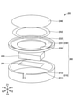
- 3 is an exploded perspective view
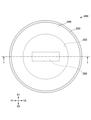
- FIG. 4 is a plan view
- FIG. 5 is a cross-sectional view taken along the line I-I in FIG.
- X1 is on the left
- X2 is on the right
- Y1 is in front
- Y2 is behind
- Z1 is up
- Z2 is down.
- the vibration generator 200 includes a lower case 210, an actuator 220, an upper case 230, and a diaphragm 240.
- the lower case 210 and the upper case 230 are included in the housing 260.
- the lower case 210 has a disk-shaped bottom plate 211 and a cylindrical side plate 212 extending upward from the edge of the bottom plate 211.
- the actuator 220 is fixed to the upper surface of the bottom plate 211 by, for example, double-sided tape 251.
- the upper case 230 has an annular bottom plate 231 having an opening 232 formed in the center, and a guide portion 233 provided on the edge of the bottom plate 231 to guide the diaphragm 240.
- the diaphragm 240 has a disk shape, is fixed to the upper surface of the bottom plate 231 by an annular double-sided tape 252 inside the guide portion 233, and is held by the upper case 230.
- the upper case 230 is fixed to the lower case 210 so that the diaphragm 240 is located above the upper case 230.
- the upper case 230 may be fixed to the lower case 210 so that the diaphragm 240 is located below the upper case 230.
- the upper case 230 is an example of a holding portion.
- the diaphragm 240 is supported by the housing 260 and generates sound by vibrating in the first direction (Z1-Z2 direction).
- the actuator 220 is attached to the housing 260 and vibrates the housing 260.
- the actuator 220 vibrates the housing 260 in the first direction at the first frequency f1 and the housing 260 in the second direction at a second frequency f2 lower than the first frequency f1.
- the second direction is a direction different from the first direction, and is preferably a direction (X1-X2 direction or Y1-Y2 direction) orthogonal to the first direction (Z1-Z2 direction).
- the diaphragm 240 is held in the upper case 230 of the housing 260.
- the diaphragm 240 is made of metal
- the housing 260 is made of synthetic resin.
- the diaphragm 240 vibrates in the first direction due to the vibration of the housing 260 in the first direction, and the diaphragm 240 vibrates the surrounding air to generate sound.
- the first frequency f1 is not particularly limited, and may be, for example, 200 Hz or more and 6 kHz or less, and particularly preferably a range that is easily detected by humans, for example, 500 Hz or more and 4 kHz or less. Even if the housing 260 vibrates at a frequency within a range that is easily detected by humans, it is difficult for humans to detect it by touch. Therefore, the vibration at the first frequency f1 in the first direction can present the sound to the human without substantially feeling the vibration.
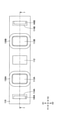
- FIG. 6 is a plan view showing the configuration of the actuator 220
- FIG. 7 is a plan view of FIG. 6 excluding the movable yoke and the permanent magnet
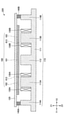
- FIG. 8 is a cross-sectional view showing the configuration of the actuator 220.
- FIG. 6 corresponds to a cross-sectional view taken along the line I-I in FIGS. 4 and 5.
- the actuator 220 includes a fixed yoke 110, a movable yoke 120, a first exciting coil 130A, a second exciting coil 130B, a first rubber 140A, a second rubber 140B, and a permanent magnet.
- the fixed yoke 110 has a plate-shaped base 111 having a substantially rectangular planar shape. The axial direction of the first exciting coil 130A and the second exciting coil 130B is parallel to the Z1-Z2 direction.
- the movable yoke 120 is an example of the first yoke
- the fixed yoke 110 is an example of the second yoke
- the first rubber 140A and the second rubber 140B are examples of the elastic support portion.
- the fixed yoke 110 further has a central protrusion 112 protruding upward (Z1 side) from the center of the base 111, and a first side protruding upward from the end (front end) on the Y1 side in the longitudinal direction of the base 111. It has a side protrusion 114A and a second side protrusion 114B that protrudes upward from the end (rear end) on the Y2 side in the longitudinal direction of the base 111.
- the first lateral protrusion 114A and the second lateral protrusion 114B are provided at positions sandwiching the central protrusion 112 in the X1-X2 direction.
- the movable yoke 120 is plate-shaped and has a substantially rectangular planar shape.
- the movable yoke 120 is in contact with the first rubber 140A and the second rubber 140B at its longitudinal end.
- a permanent magnet 160 is attached to the surface of the movable yoke 120 on the fixed yoke 110 side.
- the permanent magnet 160 has a first region 161, a second region 162 located on the Y1 side of the first region 161 and a third region 163 located on the Y2 side of the first region 161.
- the first region 161 is magnetized so as to have an S pole
- the second region 162 and the third region 163 are magnetized so as to have an N pole.
- the first region 161 faces the central protrusion 112, and the boundary 612 between the first region 161 and the second region 162 faces the first exciting coil 130A.
- the boundary 613 between the region 161 and the third region 163 is attached to the center of the movable yoke 120 in a plan view so that the boundary 613 faces the second exciting coil 130B.
- the boundary 612 is located on the Y2 side of the axis of the first exciting coil 130A
- the boundary 613 is located on the Y1 side of the axis of the second exciting coil 130B.
- the boundary 612 is located on the Y2 side of the center of the first iron core 113A
- the boundary 613 is located on the Y1 side of the center of the second iron core 113B.
- the permanent magnet 160 magnetizes the fixed yoke 110 and the movable yoke 120, and the movable yoke 120 is urged in the Z1-Z2 direction toward the fixed yoke 110 by magnetic attraction. Further, both ends of the movable yoke 120 are urged to approach each of the first lateral protrusion 114A and the second lateral protrusion 114B in the Y1-Y2 direction by the magnetic attraction force.
- the actuator 220 When generating vibration in the housing 260, the actuator 220 is driven so that the directions of the currents flowing through each of the first exciting coil 130A and the second exciting coil 130B are alternately reversed. That is, by alternately reversing the directions of the currents flowing through each of the first exciting coil 130A and the second exciting coil 130B, the magnetic poles on the surface of the first iron core 113A on the movable yoke 120 side and the second iron core 113B The magnetic poles on the surface of the movable yoke 120 side are independently inverted from each other and alternately inverted.
- the permanent magnet 160 and the movable yoke 120 reciprocate in the Y1-Y2 direction or the Z1-Z2 direction depending on the direction of the current flowing through the first exciting coil 130A and the direction of the current flowing through the second exciting coil 130B.
- Exercise The relationship between the direction of the electric current and the direction of motion will be described later.
- the first rubber 140A and the second rubber 140B have a rectangular planar shape with the X1-X2 direction as the longitudinal direction.
- the first rubber 140A is sandwiched between the first lateral protrusion 114A and the movable yoke 120
- the second rubber 140B is sandwiched between the second lateral protrusion 114B and the movable yoke 120.
- the first rubber 140A and the second rubber 140B are sandwiched between the fixed yoke 110 and the movable yoke 120. Therefore, the first rubber 140A and the second rubber 140B are held between the fixed yoke 110 and the movable yoke 120 unless they are intentionally disassembled.
- the first rubber 140A may be fixed to the upper surface of the first lateral protrusion 114A, the lower surface of the movable yoke 120, or both of them, and the second rubber 140B may be fixed to the second lateral protrusion 114B. It may be fixed to the upper surface of the rubber, the lower surface of the movable yoke 120, or both of them.
- FIG. 9 is a diagram showing the relationship between the direction of current and the direction of motion in the first combination.
- the magnetic poles on the surface of the first iron core 113A on the movable yoke 120 side are N poles
- the magnetic poles on the surface of the second iron core 113B on the movable yoke 120 side are also N poles.
- the magnetic poles on the surfaces of the central protrusion 112, the first side protrusion 114A, and the second side protrusion 114B on the movable yoke 120 side are S poles.
- a repulsive force acts between the central protrusion 112 and the first region 161
- a repulsive force acts between the first iron core 113A and the second region 162
- a repulsive force acts between the area 163 and the area 163. Therefore, a force 190U facing Z1 acts on the movable yoke 120.
- FIG. 10 is a diagram showing the relationship between the direction of current and the direction of motion in the second combination.
- the magnetic pole on the surface of the first iron core 113A on the movable yoke 120 side is the S pole
- the magnetic pole on the surface of the second iron core 113B on the movable yoke 120 side is also the S pole.
- the magnetic poles on the surfaces of the central protrusion 112, the first side protrusion 114A, and the second side protrusion 114B on the movable yoke 120 side are N poles.
- an attractive force acts between the central protrusion 112 and the first region 161 and an attractive force acts between the first iron core 113A and the second region 162, and the second iron core 113B and the third region 162.
- An attractive force acts between the region 163 and the region 163. Therefore, a force 190D facing Z2 acts on the movable yoke 120.
- the movable yoke 120 reciprocates in the Z1-Z2 direction. Exercise. That is, by energizing the first exciting coil 130A and the second exciting coil 130B, the movable yoke 120 vibrates in the Z1-Z2 direction with the position in the initial state as the neutral position. As a result, the actuator 220 vibrates in the Z1-Z2 direction as a whole.
- FIG. 11 is a diagram showing the relationship between the direction of current and the direction of motion in the third combination.
- the magnetic pole on the surface of the first iron core 113A on the movable yoke 120 side is the N pole
- the magnetic pole on the surface of the second iron core 113B on the movable yoke 120 side is the S pole.
- the magnetic pole on the surface of the first lateral protrusion 114A on the movable yoke 120 side is the S pole
- the magnetic pole on the surface of the second lateral protrusion 114B on the movable yoke 120 side is the N pole.
- FIG. 12 is a diagram showing the relationship between the direction of current and the direction of motion in the fourth combination.
- the magnetic pole on the surface of the first iron core 113A on the movable yoke 120 side is the S pole
- the magnetic pole on the surface of the second iron core 113B on the movable yoke 120 side is the N pole.
- the magnetic pole on the surface of the first lateral protrusion 114A on the movable yoke 120 side is the N pole
- the magnetic pole on the surface of the second lateral protrusion 114B on the movable yoke 120 side is the S pole.
- a repulsive force acts between the first lateral protrusion 114A and the second region 162
- a repulsive force acts between the first iron core 113A and the first region 161
- the second iron core acts.
- An attractive force acts between 113B and the first region 161 and an attractive force acts between the second lateral protrusion 114B and the third region 163. Therefore, a force 190R facing Y2 acts on the movable yoke 120.
- the movable yoke 120 reciprocates in the Y1-Y2 direction. Exercise. That is, by energizing the first exciting coil 130A and the second exciting coil 130B, the movable yoke 120 vibrates in the Y1-Y2 direction with the position in the initial state as the neutral position. As a result, the actuator 220 vibrates in the Y1-Y2 directions as a whole.
- Such an actuator 220 can be used, for example, by attaching the Z2 side surface of the fixed yoke 110 to the bottom plate 211 of the housing 260. By vibrating the actuator 220 in the Z1-Z2 direction as described above, the housing 260 vibrates in the Z1-Z2 direction, and the diaphragm 240 vibrates in the Z1-Z2 direction accordingly. Sound is generated by vibrating the air. Further, by vibrating the actuator 220 in the Y1-Y2 direction, the housing 260 vibrates in the Y1-Y2 direction, so that the vibration can be presented to the seated person through the seat 11.
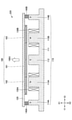
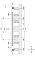
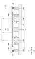
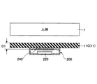
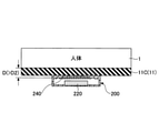
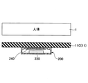
- 13A, 13B, and 13C are diagrams for explaining a non-contact state, a close contact state, and a contact state, respectively.
- 13A, 13B, and 13C show a non-contact state, a close contact state, and a contact state, respectively.
- the non-contact state is a state in which the seated person 1 (human body) is not in contact with the surface of the seat 11 (seat cloth 11C).
- the capacitance value when no one is seated on the seat 11 is smaller than that when the human body is approaching the seat 11 and when there is a seated person on the seat 11.
- the close contact state is a state in which the body of the seated person 1 is pressed against the seat 11. More specifically, the seat 11 is in a state of elastic deformation in which the seat 11 is in close contact with the seat 11 to the extent that the vibration generated by the vibration generator 200 is transmitted to the seat. If the user is seated on the seat 11, it is considered that the human body is in close contact with the diaphragm 240 of the vibration generator 200B of the seat portion 11B. Further, in the vibration generator 200A of the backrest portion 11A, the capacitance of the diaphragm 240 differs between the state in which the human body leans against the backrest portion 11A and the state in which the back is lifted.
- the distance D1 is an example of the first distance, and is the distance from the surface of the diaphragm 240 to the surface of the seat 11 in a state where no one is seated as shown in FIG. 13A.
- the distance D2 is an example of the second distance, and is shorter than the distance D1.
- the distance D2 is the distance from the surface of the diaphragm 240 to the surface of the seat 11 when there is a seated person on the seat 11. In the close contact state, the distance between the surface of the sheet 11 and the diaphragm 240 is shorter than the distance in the non-contact state, and as shown in FIG.
- the human body is in contact with the surface of the sheet 11 but is not in close contact (contact). State) shorter than. Therefore, the capacitance of the diaphragm 240 in the close contact state is larger than the capacitance in the non-contact state and the contact state.
- the determination unit 321 may determine that the diaphragm 240 is in close contact if the capacitance of the diaphragm 240 is equal to or higher than the threshold value TH2 indicating the close contact state.
- the contact state is a state in which the human body is in contact with the surface of the sheet 11 but is not in close contact with the surface as shown in FIG. 13C.
- the distance D between the surface of the sheet 11 and the surface of the diaphragm 240 in the contact state is longer than D2. Therefore, if the capacitance of the diaphragm 240 is larger than the threshold value TH1 of the capacitance and less than the threshold value TH2 when a predetermined notification condition is satisfied, the determination unit 321 determines that it is in a contact state. good.
- the determination of the close contact state and the contact state is not limited to the form of determination based on the capacitance of the diaphragm 240, but is based on the value calculated from the pressure by the pressure sensor and the elastic modulus of the backrest portion 11A.
- the determination may be made, or another sensor may be used.
- 14A to 14C are diagrams illustrating the generation of vibration or sound by the vibration generator 200.
- 14A, 14B, and 14C show the driving states of the vibration generator 200 in the non-contact state, the close contact state, and the contact state, respectively.
- the control unit 322 in the non-contact state, the control unit 322 generates a sound with a weak output level in the vibration generator 200.
- vibration cannot be transmitted to the user, the human body is not in contact with the surface of the sheet 11, and the diaphragm 240 is not covered by the human body, so that the output level is weak. This is because information can be transmitted with.
- the control unit 322 in the close contact state, the control unit 322 generates vibration in the vibration generator 200. This is because the human body is in close contact with the surface of the sheet 11 in the close contact state, so that information can be transmitted by vibration.
- the control unit 322 in the contact state, the control unit 322 generates a sound (loud sound) with a strong output level in the vibration generator 200.
- the human body In the contact state, the human body is not in close contact with the surface of the sheet 11, so it is difficult to transmit information by vibration, and since the human body covers the diaphragm 240, it is difficult to transmit sound, so the sound is more difficult than in the non-contact state. This is to raise the output level of the body and make it easier to transmit information with a stronger sound (loud sound).
- FIG. 15 is a flowchart showing an example of the process executed by the control unit 322.
- the control unit 322 determines whether or not the predetermined notification condition is satisfied (step S1).
- the predetermined notification condition is satisfied when the control unit 322 receives a notification from the ECU 12 indicating that the predetermined notification condition is satisfied.
- the control unit 322 causes the determination unit 321 to determine the state based on the capacitance of the diaphragm 240 (step S2). As a result, the determination unit 321 determines whether the contact state, the contact state, or the contact state is based on the capacitance of the diaphragm 240, and notifies the control unit 322 of the determination result.
- step S3 determines whether or not it is in the close contact state (S3: NO)
- step S5 determines whether or not it is in the contact state
- step S6 the control unit 322 generates a strong sound in the vibration generator 200
- step S5 determines in step S5 that the determination result is not in the contact state (S5: NO)
- the control unit 322 generates a weak sound in the vibration generator 200 (step S7). This completes a series of processes.
- the control unit 322 performs the above-mentioned processing individually for all the vibration generators 200.
- control unit 322 may perform the following control. Determining the three states as described above is particularly effective for the vibration generators 200A and 200C of the backrest portion 11A.
- the seated person may lean strongly against the backrest portion 11A, may lean lightly against the backrest portion 11A, or may not lean against the backrest portion 11A. When it is strongly leaning against the backrest portion 11A, it is in a close contact state, when it is lightly leaning against the backrest portion 11A, it is in a contact state, and when it is not leaning against the backrest portion 11A, it is in a non-contact state.
- the backrest portion 11A is likely to have three states of non-contact state, close contact state, and contact state, the three states are distinguished and determined, and the vibration generators 200A and 200C are driven according to the determination result. It is effective to do.
- the vibration generator 200B arranged in the seat portion 11B may be configured to determine only whether or not it is in close contact, without necessarily determining three states. Since either the sitting state or the non-sitting state is likely to occur for the seat portion 11B, the control unit 322 generates a sound in the vibration generator 200B if it is not in close contact. If it is in close contact, the vibration generator 200B may generate vibration. That is, the vibration generator 200B does not need to determine the contact state and the non-contact state.
- the vibration generator 200B arranged on the seat portion 11B can simplify the determination process as long as it has a configuration for determining only whether or not the determination unit 321 is in close contact.
- the vibration generator 200B may be configured to determine whether it is in a contact state including a close contact state or a non-contact state, instead of determining whether or not it is in a close contact state.
- the notification received from the ECU 12 may include the following data to control the seated person to notify the direction. For example, when a lane deviation occurs and the left side of the vehicle straddles the lane, the seated person by driving the vibration generators 200A, 200B, 200C provided on the left side of the seat 11 to generate vibration or sound. May be informed that a lane departure to the left has occurred. In this case, among the vibration generators 200A, 200B, and 200C, the vibration generator 200 in which the seated person's body is in close contact generates vibration, and the vibration generator 200 in contact state generates sound. Notification with direction is possible regardless of the posture of the seated person.
- vibration generators 200A are arranged in the middle stage and the lowermost stage (lower part) of the backrest portion 11A, and three vibration generators 200C are arranged in the uppermost stage (upper part). If the back of the seated person is in close contact with the upper part of the backrest portion 11A, there is a high possibility that even if sound is generated from the vibration generator 200A in the lower part, the sound is blocked by the back and does not reach the ears of the seated person. Therefore, when the determination unit 321 determines the close contact state based on the capacitance of the diaphragm 240 of the vibration generator 200C, it does not depend on the determination result based on the capacitance of the diaphragm 240 of the vibration generator 200A. In addition, the control unit 322 may not generate sound in the vibration generator 200A. Power can be saved by not generating sound in the vibration generator 200A.
- the vibration generator 200 can present vibration or sound at the position where the proximity of the seated person is detected by the diaphragm 240. Therefore, it is possible to provide a vehicle seat system 300A, a vehicle system 300, and a vibration generator 200 capable of exhibiting vibration or sound at the detected position. Further, since the diaphragm 240 that generates sound is used as the detection electrode of the capacitance sensor, space can be saved.
- the actuator 220 is not attached to the diaphragm 240 but is attached only to the housing 260. However, the actuator 220 is attached to the diaphragm 240 and the housing 260. May be good. In that case, sound can be generated by directly vibrating the diaphragm 240 due to the vibration of the actuator 220. Further, the actuator 220 may be attached only to the diaphragm 240. In that case, the vibration of the actuator 220 causes the diaphragm 240 and the housing 260 to vibrate, so that the seat can be presented with vibration through the seat 11.
- FIG. 16A is a diagram showing a vibration generator 200D of a modified example of the embodiment.
- FIG. 16B is a diagram showing a vibration generator 200E of a modified example of the embodiment.
- the diaphragm 240 is provided on the outside of the upper surface of the housing 260.
- the vibration generator 200D having such a configuration allows the body of the seated person to come into contact with the diaphragm 240 via the seat fabric 11C. Since the sound quality may change when the seated person's body is touching the diaphragm 240, it is suitable for use in which the vibration generator 200D generates vibration when the seated person's body is touching the diaphragm 240. ing.
- the diaphragm 240 is provided inside the upper surface of the housing 260, and the surface of the diaphragm 240 is offset inside the housing 260 from the upper surface of the housing 260. ..
- the vibration generator 200E having such a configuration has a configuration in which the seated person's body does not easily come into contact with the diaphragm 240 via the seat fabric 11C. Since the diaphragm 240 is offset by the thickness of the housing 260, it is configured to detect the capacitance in a non-contact manner.
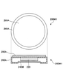
- the vibration generator 200M1 shown in FIG. 17A includes an actuator 220, a diaphragm 240M, a housing 260A, and a detection electrode 280A.
- the actuator 220 is the same as the actuator 220 shown in FIG. 2, but is attached to the top surface inside the housing 260.
- the diaphragm 240M is attached to an opening provided on the lower surface of the housing 260A and generates sound. Since the diaphragm 240M does not function as a detection electrode of the capacitance sensor, it may not contain a conductor, and may be made of, for example, a resin.
- the housing 260A is different from the housing 260 shown in FIG. 2 in that it has an opening provided with a diaphragm 240M on the lower surface and does not have an opening on the upper surface, but the other configurations are the same.
- the detection electrode 280A is a detection electrode of a sensor such as a capacitance sensor, and can detect the capacitance between the human body and the human body by, for example, a self-capacitance method.
- the detection electrode 280A has a disk shape and is provided on the upper surface of the housing 260A.
- the determination unit 321 of the controller 320 can determine the close contact state, the contact state, and the non-contact state based on the capacitance of the detection electrode 280A.
- the sensor is not limited to the capacitance sensor, and instead of the detection electrode 280A, a resistance-type pressure-sensitive sensor or the like is used to acquire physical quantities such as pressure to detect the proximity of the seated person. May be good.
- the determination unit 321 may determine the contact state, the contact state, and the non-contact state based on the physical quantity data output from the sensor.
- the vibration generator 200M2 shown in FIG. 17B includes an actuator 220, a diaphragm 240M, a housing 260, and a detection electrode 280B.
- the actuator 220 is the same as the actuator 220 shown in FIG. 2, and is provided at the bottom inside the housing 260.
- the diaphragm 240M is attached to an opening provided on the upper surface of the housing 260 and generates sound. Since the diaphragm 240M does not function as a detection electrode of the capacitance sensor, it may not contain a conductor, and may be made of, for example, a resin.
- the housing 260 is the same as the housing 260 shown in FIG.
- the detection electrode 280B is a detection electrode of a sensor such as a capacitance sensor, and can detect the capacitance between the human body and the human body by, for example, a self-capacitance method.
- the detection electrode 280B has an annular shape and is provided on the upper surface of the housing 260.
- the upper surface of the diaphragm 240M is exposed from the central opening of the annular detection electrode 280B.
- the determination unit 321 of the controller 320 can determine the close contact state, the contact state, and the non-contact state based on the capacitance of the detection electrode 280B.
- the sensor is not limited to the capacitance sensor, and instead of the detection electrode 280B, a resistance-type pressure-sensitive sensor or the like is used to acquire physical quantities such as pressure to detect the proximity of the seated person. May be good.
- the determination unit 321 may determine the contact state, the contact state, and the non-contact state based on the physical quantity data output from the sensor.
- FIG. 18A is a diagram showing a vibration generator 200M3.
- FIG. 18B is a diagram showing a vibration generator 200M4.
- FIG. 18C is a diagram showing a vibration generator 200M5.
- the vibration generator 200M3 shown in FIG. 18A has a configuration in which the detection electrode 280B of the vibration generator 200M2 shown in FIG. 17B is moved from the upper surface of the housing 260 to the top surface inside the housing 260.
- the detection electrode 280B can be configured so as not to come into direct contact with the sheet cloth 11C or the human body.
- the vibration generator 200M4 shown in FIG. 18B includes an optical sensor 280C instead of the detection electrode 280B of the vibration generator 200M2 shown in FIG. 17B.
- the optical sensor 280C is, for example, an IR (infrared) sensor, and has a light emitting unit and a light receiving unit.
- the optical sensor 280C is provided on the upper surface of the housing 260, and the seat fabric 11C is provided with a hole 11C1 in accordance with the position of the optical sensor 280C.
- the optical sensor 280C emits infrared rays from the light emitting unit through the hole 11C1 and receives the reflected wave at the light receiving unit, thereby outputting a signal according to the amount of received light to the determination unit 321.
- the determination unit 321 determines that the light receiving amount represented by the signal input from the optical sensor 280C is a non-contact state when the light receiving amount is reflected farther than the surface of the seat fabric 11C in the non-seating state. Further, when the light receiving amount represented by the signal input from the optical sensor 280C is the light receiving amount reflected at the position of the surface of the seat cloth 11C in the non-seating state, the determination unit 321 determines that the contact state is reached. Further, the determination unit 321 is in close contact when the light receiving amount represented by the signal input from the optical sensor 280C is the light receiving amount reflected at a position in front of the surface position of the seat fabric 11C in the non-seating state. Is determined.
- the light emitting unit and the light receiving unit may be integrated or may be provided separately.
- the vibration generator 200M5 shown in FIG. 18C has a configuration in which the optical sensor 280C of the vibration generator 200M4 shown in FIG. 18B is provided inside the housing 260B.
- the housing 260B of the vibration generator 200M5 has an opening 260B1 next to the opening for the diaphragm 240 on the upper surface.
- the opening 260B1 is provided to pass the infrared rays of the optical sensor 280C.
- Such a vibration generator 200M5 may be used instead of the vibration generator 200M4.
- the vibration generators 200M1 to 200M5 shown in FIGS. 17 and 18 do not have to include the diaphragm 240.
- a sound such as a notification sound may be generated from a speaker (sound generation unit) in the vehicle 10.
- the vibration generators 200M1 to 200M3 may not include the detection electrodes 280A and 280B, and the vehicle 10 may be provided with a sensor detection electrode such as a capacitance sensor provided separately from the vibration generators 200M1 to 200M3.
- the vibration generators 200M4 and 200M5 may not include the optical sensor 280C, and the vehicle 10 may be provided with an electrode of a capacitance sensor provided separately from the vibration generators 200M4 and 200M5. In these cases, the state of the seated person can be determined regardless of the posture of the seated person and the positional relationship between the vibration generators 200M1 to M5 and the seated person.
- the controller 320 is arranged on the back side of the dashboard, but the position where the controller 320 is arranged is not limited, and for example, the controller 320 may be built in the seat 11. .. Further, the controller 320 is not limited to being arranged outside the vibration generator 200, and a part or all of the controller 320 may be arranged inside the vibration generator 200.
- the actuator 220 vibrates in the first direction to generate sound from the vibrating plate 240, and the actuator 220 vibrates in the second direction to the seated person through the housing 260 and the seat 11.
- the actuator 220 may vibrate in only one direction, and may be configured to switch between sound generation and vibration presentation by switching the vibration frequency. In that case, instead of the actuator 220, an actuator capable of vibrating in only one direction may be used.
Landscapes
- Engineering & Computer Science (AREA)
- Mechanical Engineering (AREA)
- Aviation & Aerospace Engineering (AREA)
- Transportation (AREA)
- Physics & Mathematics (AREA)
- General Engineering & Computer Science (AREA)
- Theoretical Computer Science (AREA)
- Acoustics & Sound (AREA)
- Signal Processing (AREA)
- Human Computer Interaction (AREA)
- General Physics & Mathematics (AREA)
- Electromagnetism (AREA)
- Apparatuses For Generation Of Mechanical Vibrations (AREA)
- Fittings On The Vehicle Exterior For Carrying Loads, And Devices For Holding Or Mounting Articles (AREA)
- Details Of Audible-Bandwidth Transducers (AREA)
- User Interface Of Digital Computer (AREA)
- Seats For Vehicles (AREA)
Abstract
Description
図1は、車両10の内部を示す図である。車両10の室内にはシート11が配置されている。シート11は、背もたれ部(シートバック)11Aと座部(シートクッション)11Bとを有する。背もたれ部11Aと座部11Bとは、シート生地11Cに覆われている。本実施形態では、シート11が運転席のシートである例を用いて説明するが、シート11は車両10に設けられるシートであればよく、例えば助手席のシートであってもよいし、後部座席のシートであってもよい。
11 シート
11A 背もたれ部
11A1 第1領域
11A2 第2領域
11B 座部
11C シート生地
110 固定ヨーク
111 基部
112 中央突出部
113A 第1の鉄心
113B 第2の鉄心
114A 第1の側方突出部
114B 第2の側方突出部
120 可動ヨーク
130A 第1の励磁コイル
130B 第2の励磁コイル
140A 第1のラバー
140B 第2のラバー
160 永久磁石
200、200A、200B、200C 振動発生装置
210 下ケース
220 アクチュエータ
230 上ケース
240、240M 振動板
260、260A、260B 筐体
300 車両システム
300A 車両用シートシステム
320 コントローラ
321 判定部
322 制御部
Claims (11)
- 車両のシートと、
前記シートに設けられる第1振動発生装置と、を含み、
前記第1振動発生装置は、
第1筐体と、
前記第1筐体に支持される第1振動板と、
前記第1筐体及び前記第1振動板の少なくともいずれか一方に取り付けられる第1アクチュエータと、
第1検出電極を備え、当該第1検出電極への着座者の近接を検出する第1センサと
を有し、
前記第1振動板と、前記第1検出電極とが同一部材である、車両システム。 - 前記第1センサの出力に基づいて、前記シートに着座者が密着しているか否かを判定する第1判定部をさらに含む、請求項1に記載の車両システム。
- 前記第1判定部は、前記第1センサの出力に基づいて、前記第1センサから所定距離以下の位置に前記着座者がいることを検出すると、前記シートに着座者が密着していると判定する、請求項2に記載の車両システム。
- 所定の通知条件が成立した場合に、前記第1判定部によって前記シートに前記着座者が密着していると判定されていれば前記第1振動発生装置の振動によって前記シートを振動させ、前記第1判定部によって前記シートに前記着座者が密着していないと判定されていれば前記第1振動発生装置に音を発生させる第1制御部をさらに含む、請求項2又は3に記載の車両システム。
- 前記第1筐体は、前記第1アクチュエータの振動に応じて振動することで前記シートを振動させ、
前記第1振動板は、前記第1アクチュエータの振動に応じて振動することで音を発生する、請求項4に記載の車両システム。 - 前記第1判定部は、前記シートの表面に前記着座者が密着しておらず、かつ当該表面に前記着座者が接触している接触状態と、当該表面に前記着座者が接触していない非接触状態とをさらに判定し、
前記第1制御部は、前記所定の通知条件が成立した場合に、前記第1判定部が前記接触状態と判定しているときに、前記第1判定部が前記非接触状態と判定しているときよりも大きな音を前記第1振動発生装置に発生させる、請求項4又は5に記載の車両システム。 - 前記シートの座部に設けられる第2振動発生装置をさらに含み、
前記第1振動発生装置は前記シートの背もたれ部に設けられており、
前記第2振動発生装置は、
第2筐体と、
前記第2筐体に支持される第2振動板と、
前記第2筐体及び前記第2振動板の少なくともいずれか一方に取り付けられる第2アクチュエータと、
第2検出電極を備え、当該第2検出電極への前記着座者の近接を検出する第2センサと
を有し、
前記第2センサの出力に基づいて、前記座部に前記着座者が密着しているか否かを判定する第2判定部と、
前記所定の通知条件が成立した場合に、前記第2判定部によって前記座部に前記着座者が密着していると判定されていれば前記第2振動発生装置の振動によって前記座部を振動させ、前記第2判定部によって前記座部に前記着座者が密着していないと判定されていれば前記第2振動発生装置に音を発生させる第2制御部とをさらに含む、請求項6に記載の車両システム。 - 前記第2判定部は、前記座部に前記着座者が密着しているか否かのみを判定する、請求項7に記載の車両システム。
- 前記第1振動発生装置を複数含み、
前記第1判定部は、前記複数の第1振動発生装置が設けられる前記シートのそれぞれの位置に前記着座者が密着しているか否かを判定する、
請求項2乃至8のいずれか1項に記載の車両システム。 - 前記第1振動発生装置は、前記シートの背もたれ部の第1領域に設けられており、
前記背もたれ部の前記第1領域より上方の第2領域に設けられる第3振動発生装置をさらに含み、
前記第3振動発生装置は、
第3筐体と、
前記第3筐体に支持される第3振動板と、
前記第3筐体及び前記第3振動板の少なくともいずれか一方に取り付けられる第3アクチュエータと、
第3検出電極を備え、当該第3検出電極への前記着座者の近接を検出する第3センサと
を有し、
前記第3センサの出力に基づいて、前記背もたれ部の前記第2領域に前記着座者が密着しているか否かを判定する第3判定部と、
前記所定の通知条件が成立した場合に、前記第3判定部によって前記背もたれ部の前記第2領域に前記着座者が密着していると判定されていれば、前記第1判定部の判定結果によらず、前記第3振動発生装置の振動によって前記シートを振動させつつ前記第1制御部に前記第1振動発生装置には音を発生させない、第3制御部と
をさらに含む、請求項4乃至8のいずれか1項に記載の車両システム。 - 車両のシートに設けられる振動発生装置であって、
筐体と、
前記筐体に支持される振動板と、
前記筐体及び前記振動板の少なくともいずれか一方に取り付けられるアクチュエータと、
検出電極を備え、当該検出電極への近接を検出するセンサと
を有し、
前記振動板と前記検出電極とが同一部材である、振動発生装置。
Priority Applications (5)
| Application Number | Priority Date | Filing Date | Title |
|---|---|---|---|
| CN202510886393.9A CN120730227A (zh) | 2020-07-14 | 2021-05-13 | 车辆系统及振动产生装置 |
| CN202180042108.5A CN115699800B (zh) | 2020-07-14 | 2021-05-13 | 车辆系统及振动产生装置 |
| JP2022536148A JP7407290B2 (ja) | 2020-07-14 | 2021-05-13 | 車両システム及び振動発生装置 |
| US18/054,240 US12128805B2 (en) | 2020-07-14 | 2022-11-10 | Vehicle system and vibration generation device |
| US18/889,895 US20250010778A1 (en) | 2020-07-14 | 2024-09-19 | Vehicle system and vibration generation device |
Applications Claiming Priority (2)
| Application Number | Priority Date | Filing Date | Title |
|---|---|---|---|
| JP2020-120777 | 2020-07-14 | ||
| JP2020120777 | 2020-07-14 |
Related Child Applications (1)
| Application Number | Title | Priority Date | Filing Date |
|---|---|---|---|
| US18/054,240 Continuation US12128805B2 (en) | 2020-07-14 | 2022-11-10 | Vehicle system and vibration generation device |
Publications (1)
| Publication Number | Publication Date |
|---|---|
| WO2022014135A1 true WO2022014135A1 (ja) | 2022-01-20 |
Family
ID=79554664
Family Applications (1)
| Application Number | Title | Priority Date | Filing Date |
|---|---|---|---|
| PCT/JP2021/018276 Ceased WO2022014135A1 (ja) | 2020-07-14 | 2021-05-13 | 車両システム及び振動発生装置 |
Country Status (4)
| Country | Link |
|---|---|
| US (2) | US12128805B2 (ja) |
| JP (1) | JP7407290B2 (ja) |
| CN (2) | CN120730227A (ja) |
| WO (1) | WO2022014135A1 (ja) |
Cited By (3)
| Publication number | Priority date | Publication date | Assignee | Title |
|---|---|---|---|---|
| WO2023171078A1 (ja) * | 2022-03-07 | 2023-09-14 | アルプスアルパイン株式会社 | 触覚提示装置、シートシステム、及び触覚提示方法 |
| JP2023132331A (ja) * | 2022-03-10 | 2023-09-22 | 株式会社デンソーテン | 振動シートおよび再生システム |
| WO2024209841A1 (ja) * | 2023-04-07 | 2024-10-10 | アルプスアルパイン株式会社 | 振動発生装置、触覚提示装置、及び、シートシステム |
Families Citing this family (3)
| Publication number | Priority date | Publication date | Assignee | Title |
|---|---|---|---|---|
| EP4289313B1 (en) * | 2021-02-04 | 2025-11-19 | TS Tech Co., Ltd. | Seat device for vehicle |
| KR20250025245A (ko) * | 2023-08-14 | 2025-02-21 | 현대자동차주식회사 | 차량의 주행 감성 제공 시스템 및 방법 |
| CN120101927B (zh) * | 2025-05-08 | 2025-07-15 | 西华大学 | 一种新能源汽车噪音测试系统 |
Citations (3)
| Publication number | Priority date | Publication date | Assignee | Title |
|---|---|---|---|---|
| JP2002017513A (ja) * | 2000-07-10 | 2002-01-22 | Beat Sonic:Kk | 音響用シート |
| JP2019077432A (ja) * | 2017-10-20 | 2019-05-23 | クラリオン株式会社 | 報知装置および報知方法 |
| WO2019244755A1 (ja) * | 2018-06-21 | 2019-12-26 | ソニー株式会社 | 振動提示装置及び振動提示方法 |
Family Cites Families (16)
| Publication number | Priority date | Publication date | Assignee | Title |
|---|---|---|---|---|
| JP2006007919A (ja) | 2004-06-24 | 2006-01-12 | Mazda Motor Corp | 車両用操作ユニット |
| US8274383B2 (en) * | 2008-03-31 | 2012-09-25 | The Boeing Company | Methods and systems for sensing activity using energy harvesting devices |
| US8339285B2 (en) * | 2009-07-27 | 2012-12-25 | The Boeing Company | Tactile pilot alerting system and method |
| JP2016068667A (ja) * | 2014-09-29 | 2016-05-09 | アイシン精機株式会社 | 車両用の情報伝達装置 |
| WO2016158758A1 (ja) * | 2015-03-27 | 2016-10-06 | テイ・エス テック株式会社 | 検出器付きのシート |
| WO2018027168A1 (en) * | 2016-08-05 | 2018-02-08 | Subpac, Inc. | Transducer system providing tactile sensations |
| JP6356882B1 (ja) * | 2017-07-31 | 2018-07-11 | テイ・エス テック株式会社 | シートへのセンサーの配置構造 |
| JP6879169B2 (ja) * | 2017-11-02 | 2021-06-02 | 株式会社デンソー | 超音波センサ |
| CN108040316A (zh) * | 2017-11-24 | 2018-05-15 | 维沃移动通信有限公司 | 一种振幅检测方法及移动终端 |
| US11052223B2 (en) * | 2017-12-21 | 2021-07-06 | Lear Corporation | Seat assembly and method |
| US11279265B2 (en) * | 2018-09-06 | 2022-03-22 | Honda Motor Co., Ltd | System and method for counteracting vibrations within a vehicle |
| EP3939709B1 (en) * | 2019-03-14 | 2024-10-23 | Alps Alpine Co., Ltd. | Vibration generation device |
| US20210038435A1 (en) * | 2019-08-07 | 2021-02-11 | Subpac, Inc. | Contextualized equalization |
| CN110839196B (zh) * | 2019-10-28 | 2021-06-08 | 华为终端有限公司 | 一种电子设备及其播放控制方法 |
| FR3122129B1 (fr) * | 2021-04-22 | 2025-05-30 | Faurecia Sieges Dautomobile | Garniture d’élément de siège de véhicule intégrant un dispositif vibrant |
| US11618361B2 (en) * | 2021-04-30 | 2023-04-04 | Aac Microtech (Changzhou) Co., Ltd. | Bass automobile seat module and automobile |
-
2021
- 2021-05-13 JP JP2022536148A patent/JP7407290B2/ja active Active
- 2021-05-13 CN CN202510886393.9A patent/CN120730227A/zh active Pending
- 2021-05-13 WO PCT/JP2021/018276 patent/WO2022014135A1/ja not_active Ceased
- 2021-05-13 CN CN202180042108.5A patent/CN115699800B/zh active Active
-
2022
- 2022-11-10 US US18/054,240 patent/US12128805B2/en active Active
-
2024
- 2024-09-19 US US18/889,895 patent/US20250010778A1/en active Pending
Patent Citations (3)
| Publication number | Priority date | Publication date | Assignee | Title |
|---|---|---|---|---|
| JP2002017513A (ja) * | 2000-07-10 | 2002-01-22 | Beat Sonic:Kk | 音響用シート |
| JP2019077432A (ja) * | 2017-10-20 | 2019-05-23 | クラリオン株式会社 | 報知装置および報知方法 |
| WO2019244755A1 (ja) * | 2018-06-21 | 2019-12-26 | ソニー株式会社 | 振動提示装置及び振動提示方法 |
Cited By (4)
| Publication number | Priority date | Publication date | Assignee | Title |
|---|---|---|---|---|
| WO2023171078A1 (ja) * | 2022-03-07 | 2023-09-14 | アルプスアルパイン株式会社 | 触覚提示装置、シートシステム、及び触覚提示方法 |
| JP2023132331A (ja) * | 2022-03-10 | 2023-09-22 | 株式会社デンソーテン | 振動シートおよび再生システム |
| JP7837182B2 (ja) | 2022-03-10 | 2026-03-30 | 株式会社デンソーテン | 振動シート |
| WO2024209841A1 (ja) * | 2023-04-07 | 2024-10-10 | アルプスアルパイン株式会社 | 振動発生装置、触覚提示装置、及び、シートシステム |
Also Published As
| Publication number | Publication date |
|---|---|
| US20250010778A1 (en) | 2025-01-09 |
| CN115699800B (zh) | 2025-07-11 |
| US20230075857A1 (en) | 2023-03-09 |
| CN120730227A (zh) | 2025-09-30 |
| CN115699800A (zh) | 2023-02-03 |
| JPWO2022014135A1 (ja) | 2022-01-20 |
| US12128805B2 (en) | 2024-10-29 |
| JP7407290B2 (ja) | 2023-12-28 |
Similar Documents
| Publication | Publication Date | Title |
|---|---|---|
| JP7407290B2 (ja) | 車両システム及び振動発生装置 | |
| US20130201127A1 (en) | Input device | |
| JP6833835B2 (ja) | タクト・インターフェースモジュール、及び触覚フィードバックを生成するための方法 | |
| JP2013540328A (ja) | 触覚フィードバック接触感知式インタフェースモジュール | |
| JP2014132452A (ja) | ハプティックフィードバックデバイス | |
| JP6828029B2 (ja) | タクト・インターフェースモジュールのアクチュエータ、タクト・インターフェースモジュール、及び触覚フィードバックを生成する方法 | |
| JP2012524506A (ja) | 電磁アクチュエータ及び触感フィードバックを有する関連制御装置 | |
| WO2020044632A1 (ja) | 操作装置及び振動発生装置 | |
| US20220300078A1 (en) | Operation device | |
| JP6117075B2 (ja) | 触覚呈示装置 | |
| WO2019181378A1 (ja) | 運転支援装置 | |
| CN113396019B (zh) | 电磁驱动装置以及操作装置 | |
| EP3939709B1 (en) | Vibration generation device | |
| JP6777497B2 (ja) | 力覚呈示装置 | |
| WO2020044631A1 (ja) | 操作装置及び振動発生装置 | |
| JP2021114122A (ja) | 操作装置 | |
| JP2017004264A (ja) | 触覚呈示装置 | |
| WO2026014274A1 (ja) | シート装置 | |
| JP2024106492A (ja) | 振動デバイス、及び振動シート | |
| JP2025012216A (ja) | 触覚呈示装置 | |
| WO2019202814A1 (ja) | 電子機器 | |
| JP2012109041A (ja) | 入力装置 | |
| JP2020184154A (ja) | 力覚提示装置 |
Legal Events
| Date | Code | Title | Description |
|---|---|---|---|
| 121 | Ep: the epo has been informed by wipo that ep was designated in this application |
Ref document number: 21843426 Country of ref document: EP Kind code of ref document: A1 |
|
| ENP | Entry into the national phase |
Ref document number: 2022536148 Country of ref document: JP Kind code of ref document: A |
|
| NENP | Non-entry into the national phase |
Ref country code: DE |
|
| 122 | Ep: pct application non-entry in european phase |
Ref document number: 21843426 Country of ref document: EP Kind code of ref document: A1 |
|
| WWG | Wipo information: grant in national office |
Ref document number: 202180042108.5 Country of ref document: CN |