WO2022013988A1 - 通信装置、通信方法、通信システムおよび通信プログラム - Google Patents
通信装置、通信方法、通信システムおよび通信プログラム Download PDFInfo
- Publication number
- WO2022013988A1 WO2022013988A1 PCT/JP2020/027564 JP2020027564W WO2022013988A1 WO 2022013988 A1 WO2022013988 A1 WO 2022013988A1 JP 2020027564 W JP2020027564 W JP 2020027564W WO 2022013988 A1 WO2022013988 A1 WO 2022013988A1
- Authority
- WO
- WIPO (PCT)
- Prior art keywords
- wavelength
- transmission
- communication device
- communication
- amount
- Prior art date
- Legal status (The legal status is an assumption and is not a legal conclusion. Google has not performed a legal analysis and makes no representation as to the accuracy of the status listed.)
- Ceased
Links
Images


Classifications
-
- H—ELECTRICITY
- H04—ELECTRIC COMMUNICATION TECHNIQUE
- H04J—MULTIPLEX COMMUNICATION
- H04J14/00—Optical multiplex systems
- H04J14/02—Wavelength-division multiplex systems
- H04J14/0227—Operation, administration, maintenance or provisioning [OAMP] of WDM networks, e.g. media access, routing or wavelength allocation
-
- H—ELECTRICITY
- H04—ELECTRIC COMMUNICATION TECHNIQUE
- H04J—MULTIPLEX COMMUNICATION
- H04J14/00—Optical multiplex systems
- H04J14/02—Wavelength-division multiplex systems
- H04J14/0201—Add-and-drop multiplexing
-
- H—ELECTRICITY
- H04—ELECTRIC COMMUNICATION TECHNIQUE
- H04J—MULTIPLEX COMMUNICATION
- H04J14/00—Optical multiplex systems
- H04J14/02—Wavelength-division multiplex systems
- H04J14/0227—Operation, administration, maintenance or provisioning [OAMP] of WDM networks, e.g. media access, routing or wavelength allocation
- H04J14/0254—Optical medium access
- H04J14/0256—Optical medium access at the optical channel layer
- H04J14/0257—Wavelength assignment algorithms
-
- H—ELECTRICITY
- H04—ELECTRIC COMMUNICATION TECHNIQUE
- H04L—TRANSMISSION OF DIGITAL INFORMATION, e.g. TELEGRAPHIC COMMUNICATION
- H04L12/00—Data switching networks
- H04L12/28—Data switching networks characterised by path configuration, e.g. LAN [Local Area Networks] or WAN [Wide Area Networks]
- H04L12/42—Loop networks
-
- H—ELECTRICITY
- H04—ELECTRIC COMMUNICATION TECHNIQUE
- H04J—MULTIPLEX COMMUNICATION
- H04J14/00—Optical multiplex systems
- H04J14/02—Wavelength-division multiplex systems
-
- H—ELECTRICITY
- H04—ELECTRIC COMMUNICATION TECHNIQUE
- H04J—MULTIPLEX COMMUNICATION
- H04J14/00—Optical multiplex systems
- H04J14/02—Wavelength-division multiplex systems
- H04J14/0278—WDM optical network architectures
- H04J14/0283—WDM ring architectures
-
- H—ELECTRICITY
- H04—ELECTRIC COMMUNICATION TECHNIQUE
- H04J—MULTIPLEX COMMUNICATION
- H04J14/00—Optical multiplex systems
- H04J14/08—Time-division multiplex systems
Definitions
- the present invention relates to a technique for performing time division multiplexing and communication of optical signals for each wavelength in a wavelength division multiplexing optical ring network constituting a communication system.
- optical signals of wavelengths assigned in advance to each of a plurality of optical transmission devices connected to the optical ring network are multiplexed and communicated by OADM (Optical add-drop multiplexer) technology.
- OADM Optical add-drop multiplexer
- a burst optical ring network technology that transmits an optical signal by time division multiplexing instead of an OADM is known.
- one optical transmission device operates as a master device and the other optical transmission device operates as a child device among a plurality of optical transmission devices connected to an optical ring network.
- the parent device controls the data transmission timing of all the devices including the own device.
- DBA Dynamic Bandwidth Allocation
- priority control are being studied as band allocation technology in GE-PON (Gigabit Ethernet (registered trademark) -Passive Optical Network) (see, for example, Non-Patent Document 2).
- GE-PON Gigabit Ethernet (registered trademark) -Passive Optical Network
- TDM Time Division Multiplexing
- the child device When multiple optical transmission devices connected to a wavelength division multiplexing optical ring network perform DBA, the child device notifies the amount of data to be transmitted stored in the buffer and requests a transmission band. To the parent device (transmission request amount). The parent device transmits a Gate message for allocating a transmission band to each child device based on a Report message received from a plurality of child devices (transmission permission amount). This makes it possible to allocate the transmission band according to the amount of data in the buffer of the child device.
- the present invention improves the communication efficiency of the entire system by leveling the band utilization rate between wavelengths when connected to an optical ring network having wavelength division multiplexing and communication is performed by time-dividing and multiplexing optical signals for each wavelength. It is an object of the present invention to provide a communication device, a communication method, a communication system and a communication program which can be used.
- the communication device of the present invention is connected to a wavelength-division-multiplexed optical ring network, and performs communication by time-dividing and multiplexing optical signals for each wavelength, and also obtains a transmission request amount for requesting a transmission band from a parent communication device. Based on the communication unit that transmits and receives the transmission permission amount for allocating the transmission band from the parent communication device, the transmission request amount, and the transmission permission amount, the band utilization rate for each wavelength is estimated, and the bandwidth between wavelengths is estimated. It is characterized by having a control unit that distributes data to each wavelength so that the band utilization rate of the above is leveled.
- the present invention is a communication used in a communication system in which optical signals are time-divided and multiplexed for each wavelength via a wavelength-multiplexed optical ring network in which a parent communication device and a child communication device are connected.
- the parent communication device receives a transmission request amount for requesting a transmission band from a plurality of the child communication devices, and is a transmission permission for allocating a transmission band to each of the child communication devices.
- the child communication device transmits the amount, and the child communication device determines the band utilization rate for each wavelength based on the transmission request amount transmitted to the parent communication device and the transmission permission amount received from the parent communication device. It is characterized by estimating and distributing data to each wavelength so that the band utilization rate between wavelengths is leveled.
- the present invention also relates to a communication system in which optical signals are time-divided and multiplexed for each wavelength via a wavelength-multiplexed optical ring network in which a parent communication device and a child communication device are connected.
- the parent communication device receives a transmission request amount for requesting a transmission band from a plurality of the child communication devices, and transmits a transmission permission amount for allocating the transmission band to each of the child communication devices.
- the child communication device estimates the band utilization rate for each wavelength based on the transmission request amount transmitted to the parent communication device and the transmission permission amount received from the parent communication device, and the band utilization rate between wavelengths is estimated. It is characterized in that data is distributed to each wavelength so that the band utilization rate is leveled.
- the communication program of the present invention is characterized in that a computer or an integrated circuit is made to execute a process performed by the control unit of the communication device.
- the communication device, communication method, communication system, and communication program according to the present invention are connected to an optical ring network in which wavelengths are multiplexed, and band utilization between wavelengths is used when optical signals are time-divided and multiplexed for each wavelength for communication.
- the rate can be leveled and the communication efficiency of the entire system can be improved.
- an optical ring network system (corresponding to a communication system) in which a plurality of optical transmission devices (corresponding to a communication device) are connected by an optical ring network will be described.
- FIG. 1 shows an example of an optical ring network system 100 according to an embodiment.
- the optical transmission device 101-A, the optical transmission device 101-B, the optical transmission device 101-C, and the optical transmission device 101-D are ring-shaped networks (optical ring network 102) composed of optical fibers. ) Is connected.
- the alphabet at the end of the reference numeral is omitted and the optical transmission device is omitted. It is described as 101.
- an alphabet is added to the end of the reference numeral and the description is made, for example, optical transmission device 101-A.
- An external NW 103 is connected to each optical transmission device 101, and communication between these external NW 103s is possible via the optical ring network 102.
- the data received from the external NW 103 is distributed to optical signals having a plurality of wavelengths to be wavelength-multiplexed and transmitted to the optical transmission device 101 of the communication destination.
- the external NW 103 is a NW connected to the above-mentioned optical ring network system 100, and a NW device or the like is connected to the external NW 103.
- the optical ring network system 100 performs wavelength division multiplexing of optical signals for communication.
- n optical signals having n wavelengths of ⁇ 1-n are wavelength-multiplexed.
- the optical ring network system 100 uses burst optical ring network technology.
- the plurality of optical transmission devices 101 perform time division multiplexing (optical TDMA (Time Division Multiple Access)) of optical signals for each wavelength and communicate on the optical ring network 102.
- time division multiplexing optical TDMA (Time Division Multiple Access)
- one optical transmission device 101 is a parent device (corresponding to a parent communication device), and the other optical transmission device 101 is a child device (corresponding to a child communication device).
- the parent device controls the transmission timing of optical signals of all devices for each wavelength.
- the parent device in the initial state is predetermined. For example, when the optical transmission device 101-A is the parent device, the optical transmission device 101-B, the optical transmission device 101-C, and the optical transmission device 101-D are used. It becomes a child device.
- the child device may have a function that one of the child devices operates as a new parent device when the parent device fails.
- the optical transmission device 101 (for example, optical transmission device 101-B) of the child device transmits a report message for requesting a transmission band to the optical transmission device 101 (for example, optical transmission device 101-A) of the parent device. (Transmission request amount). Then, the optical transmission device 101 (for example, optical transmission device 101-A) of the parent device transmits (transmission) a Gate message for allocating the transmission band to the optical transmission device 101 (for example, optical transmission device 101-B) of the child device. Allowed amount).
- the optical transmission device 101 of the child device estimates the band utilization rate for each wavelength based on the transmission request amount transmitted to the parent device for each wavelength and the transmission permission amount received from the parent device.
- the optical transmission device 101 of the slave device distributes the data received from the external NW 103 to the buffer corresponding to each wavelength so that the band utilization rate between wavelengths is leveled.
- the optical transmission device 101 of the slave device estimates the band utilization rate for each wavelength based on the transmission request amount and the transmission permission amount, so that the band utilization rate between wavelengths is leveled.
- the amount of data to be distributed to the buffer of each wavelength is weighted.
- the optical ring network system 100 according to the embodiment can distribute data preferentially to a buffer having a wavelength having a low band utilization rate, aim at leveling the band utilization rate between wavelengths, and communicate efficiency of the entire system. Can be improved.
- optical transmission device 101 (Configuration example of optical transmission device 101)
- the four optical transmission devices 101 described with reference to FIG. 1 have both functions of a parent device and a child device, and one of the functions can be selected to operate as a parent device or a child device.
- the optical transmission device 101-A when the function of the master device is selected, the optical transmission device 101-A operates as a master device, and when the function of the child device is selected, the optical transmission device 101-A operates as a child device.
- the optical transmission device 101-A is in operation as a master device
- the optical transmission device 101-B, the optical transmission device 101-C, and the optical transmission device 101-D are in operation as child devices.
- FIG. 2 shows a configuration example of an optical transmission device 101-B that operates as a child device shown in FIG.
- the optical transmission device 101-C and the optical transmission device 101-D which operate as the same child devices as the optical transmission device 101-B, operate in the same manner as the optical transmission device 101-B.
- the optical transmission device 101-B has a layer 1 processing unit (L1 unit) 201, a layer 2 processing unit (L2 unit) 202, a switch unit (SW unit) 203, and an optical transmission unit (B-Tx unit) 204. It has an optical receiving unit (B-Rx unit) 205, an optical coupler 206, an optical coupler 207, a difference calculation unit 215, a sorting unit 216, and a distribution control unit 221.
- L1 unit layer 1 processing unit
- L2 unit layer 2 processing unit
- SW unit switch unit
- B-Tx unit optical transmission unit
- the L1 unit 201 has a function of processing the first layer (physical layer) of the OSI reference model.
- the L2 unit 202 has a function of processing the second layer (data link layer) of the OSI reference model. Further, the L2 unit 202 has a function for operating as a parent device and a function for operating as a child device, and either function can be selected by setting. For example, the L2 unit 202 of the optical transmission device 101-A of the parent device operates as a parent device, and the L2 unit 202 of the optical transmission device 101-B of the child device operates as a child device. In the case of the child device, a function for detecting the failure of the parent device may be provided so that the child device operates as a new parent device when the failure of the parent device is detected.
- the SW unit 203 is an electric packet switch such as an L2-SW connected to the external NW103-B, and has a function of processing a packet transfer between the L2 unit 202 and the external NW103-B according to a preset rule. Have. The configuration of the SW unit 203 will be described in detail later.
- the B-Tx unit 204 is a transmission unit that intermittently outputs an optical signal, and transmits the signal transferred from the L1 unit 201 as an optical signal to the optical fiber via an optical coupler in a burst manner. Further, the B-Tx unit 204 has a transmission unit (Tx) for each of a plurality of wavelengths. For example, it has Tx204 (1) having a wavelength ⁇ 1 and Tx204 (2) having a wavelength ⁇ 2, ... Tx204 (n) having a wavelength ⁇ n (not shown). For example, Tx204 (1) bursts the signal transferred from the L1 unit 201 as an optical signal having a wavelength of ⁇ 1.
- the B-Rx unit 205 is a receiving unit that receives an intermittent optical signal, receives an optical signal in a burst from an optical fiber via an optical coupler, and transfers the signal to the L1 unit 201. Further, the B-Rx unit 205 has a receiving unit (Rx) for each of a plurality of wavelengths. For example, it has Rx205 (1) having a wavelength ⁇ 1 and Rx205 (2) having a wavelength ⁇ 2, ... Rx205 (n) having a wavelength ⁇ n (not shown). For example, Rx205 (1) receives an optical signal from an optical fiber in a burst and transfers the signal to the L1 unit 201.
- the B-Tx unit 204 and the B-Rx unit 205 correspond to the communication unit.
- the optical coupler 206 and the optical coupler 207 have a function of branching the power of the input optical signal.
- the SW unit 203 includes a scheduler unit 251, a buffer unit 252, a distribution unit 253, a Gate reception unit 254, and a Report transmission unit 255.
- the scheduler unit 251 has a scheduler 261 for each wavelength, and transmits the data stored in the buffer unit 252 based on the Gate message received from the parent device by the Gate receiving unit 254 described later. Specifically, the scheduler 261 transmits data stored in the buffer 262 of the wavelength in charge at the transmission timing and transmission time specified by the Gate message from the B-Tx unit 204.
- the transmission at the wavelength ⁇ 1 corresponds to the scheduler 261 (1)
- the transmission at the wavelength ⁇ 2 corresponds to the scheduler 261 (2).
- transmission speed ⁇ transmission time transmission permission amount
- the child device can obtain the transmission permission amount based on the transmission timing and transmission time notified by the parent device in the Gate message.
- the parent device may notify the child device of the transmission permission amount itself.
- the buffer unit 252 has a buffer 262 for each wavelength, and stores data distributed to each wavelength by the distribution unit 253.
- the wavelength ⁇ 1 corresponds to the buffer 262 (1)
- the wavelength ⁇ 2 corresponds to the buffer 262 (2).
- the amount of data stored in the buffer 262 for each wavelength is acquired by the Report transmission unit 255 described later.
- the distribution unit 253 distributes the transmission data input from the external NW103-B to the buffer 262 for each wavelength.
- the distribution unit 253 distributes the transmission data input from the external NW103-B to the buffer 262 of each wavelength at a ratio weighted by the distribution control unit 221.
- WRR Weighted RR
- a distribution method other than WRR may be used.
- the Gate receiving unit 254 receives the Gate message transmitted from the optical transmission device 101-A of the parent device to the child device, and outputs the Gate message to the scheduler unit 251 and the difference calculation unit 215.
- the parent device may transmit a Gate message for each wavelength, or may transmit each Gate message of a plurality of wavelengths as one Gate message.
- the Gate message is output to the scheduler unit 251 and the difference calculation unit 215.
- the Report transmission unit 255 acquires the amount of data stored in the buffer 262 for each wavelength, notifies the parent device as a transmission request amount by a Report message, and outputs the data to the difference calculation unit 215.
- the Report transmission unit 255 may transmit a Report message for each wavelength to the parent device, or may transmit each Report message of a plurality of wavelengths to the parent device as one Report message.
- the Report message is transmitted to the parent device via the buffer unit 252 and the scheduler unit 251.
- the difference calculation unit 215 calculates the difference ⁇ between the transmission request amount of the Report message transmitted to the parent device for each wavelength and the transmission permission amount of the Gate message received from the parent device (Equation (1)).
- the difference ⁇ 1 of the wavelength ⁇ 1 when using three wavelengths, for example, the difference ⁇ 1 of the wavelength ⁇ 1, the difference ⁇ 2 of the wavelength ⁇ 2, and the difference ⁇ 3 of the wavelength ⁇ 3, the following list can be created in order of wavelength for the difference ⁇ for each wavelength. be.
- the sorting unit 216 has a function of rearranging the list based on the size of the difference ⁇ calculated by the difference calculation unit 215. For example, in the above list, it is assumed that the magnitude of the difference ⁇ has a relationship of ⁇ 3> ⁇ 2> ⁇ 1. In this case, the sorting unit 216 sorts the list in order of wavelength from the one with the largest difference ⁇ in descending order as follows.
- the wavelength having a large difference ⁇ is a state in which a sufficient transmission permission amount is not allocated to the transmission request amount, and a large amount of data is accumulated in the buffer 262 of the wavelength, and the wavelength having a small difference ⁇ .
- Band utilization is lower than. That is, the larger the difference ⁇ is, the lower the band utilization rate is, and the smaller the difference ⁇ is, the higher the band utilization rate is.
- the distribution control unit 221 weights the data received from the external NW 103 by the distribution unit 253 when it distributes the data received from the external NW 103 to the buffer 262 for each wavelength according to the order in which the sorting unit 216 rearranges.
- the weighting is light for wavelengths with a small difference ⁇ (high band utilization rate) and heavy for wavelengths with a large difference ⁇ (low band utilization rate).
- the total weighting factor is 1, the weighting factor of the wavelength ⁇ 3 with the largest difference ⁇ 3 is 0.6, the weighting factor of the second largest wavelength ⁇ 2 is 0.3, and the wavelength with the smallest difference ⁇ .
- Each weighting is performed so that the weighting coefficient of ⁇ 1 is 0.1.
- the data received from the external NW103 is distributed to each buffer 262 having wavelengths ⁇ 3, ⁇ 2, and ⁇ 1 at a ratio of, for example, 6 packets: 3 packets: 1 packet.
- the optical transmission device 101 operating as a child device estimates the band utilization rate for each wavelength based on the transmission request amount and the transmission permission amount, so that the band utilization rate between wavelengths is leveled. , The amount of data to be distributed to the buffer 262 of each wavelength is weighted. As a result, the amount of data to be distributed to the buffer 262 having a high bandwidth utilization rate is reduced, and the amount of data to be distributed to the buffer 262 having a low bandwidth utilization rate is increased. The overall communication efficiency is improved.
- the parent device calculates the difference ⁇ between the amount of data stored in the buffer of the own device and the transmission permission amount allocated to the own device for each wavelength, and receives the data received from the external NW103 connected to the own device. Weight and distribute to the buffer for each wavelength.
- FIG. 3 shows an example of weighting processing of data distribution in the optical transmission device 101 operating as a child device.
- the processing of FIG. 3 includes, for example, the difference calculation unit 215, the sorting unit 216, the distribution control unit 221 and the Gate receiving unit 254 and the Report transmission unit 255 in the optical transmission device 101-B of the child device described with reference to FIG. Is executed by.
- the program corresponding to the process described with reference to FIG. 3 may be executed by a computer or an integrated circuit such as an FPGA (Field Programmable Gate Array). Further, the program may be recorded on a storage medium and provided, or may be provided through a network.
- FPGA Field Programmable Gate Array
- step S101 the optical transmission device 101 operating as a child device starts a process of weighting when distributing data received from the external NW 103.
- step S102 the Report transmission unit 255 notifies the parent device of the amount of data to be transmitted (transmission request amount) stored in the buffer 262 and transmits a Report message for requesting the transmission band. Since the Report message is transmitted to the parent device at a predetermined transmission timing, it waits until the transmission timing is reached. After transmitting the Report message, the process proceeds to step S103.
- step S103 the Gate receiving unit 254 determines whether or not a Gate message for notifying each child device of the transmission band (transmission permitted amount) has been received from the parent device.
- the Gate message is received (Y)
- the process proceeds to the process of step S104, and when the Gate message is not received (N), the process waits in step S103 until the Gate message is received.
- step S104 the difference calculation unit 215 describes the transmission request amount transmitted to the parent device in step S102 and the transmission permission amount received from the parent device in step S103 as described in the above equation (1).
- the difference ⁇ is calculated for each wavelength.
- step S105 the sorting unit 216 sorts the list of the difference ⁇ in the order of wavelength in descending order from the one with the largest difference ⁇ .
- step S106 the distribution control unit 221 determines the weighting for the distribution unit 253 when the data received from the external NW 103 is distributed to the buffer 262 for each wavelength according to the order sorted in step S105. Then, the distribution control unit 221 instructs the distribution unit 253 to distribute the data received from the external NW 103 to the buffer 262 for each wavelength based on the determined weighting.
- step S107 the optical transmission device 101 operating as a child device ends the process of weighting when distributing the data received from the external NW 103.
- step S102 While the optical transmission device 101 is in operation, the processes from step S102 to step S106 are repeatedly executed, and the weighting is changed as the difference ⁇ changes.
- the band utilization rate is 80% and the difference ⁇ is 20.
- the band utilization rate is 20%, and the difference ⁇ is 80. That is, the bandwidth utilization rate is low when the difference ⁇ is large, and the bandwidth utilization rate is high when the difference ⁇ is small. Therefore, in the optical transmission device 101 according to the embodiment, in order to equalize the band utilization rate between wavelengths, the weight is increased as the wavelength has a lower band utilization rate, and the weight is decreased as the wavelength has a higher band utilization rate.
- the optical transmission device 101 operating as the child device calculates the difference ⁇ between the transmission request amount and the transmission permission amount for each wavelength, and receives from the external NW 103 based on the magnitude of the difference ⁇ .
- the data to be used is weighted and distributed to the buffer 262 for each wavelength.
- the distribution of data to the buffer 262 having a wavelength with a large difference ⁇ (low band utilization rate) is prioritized, and the amount of data distributed to the buffer 262 having a wavelength with a small difference ⁇ (high band utilization rate) is reduced. ..
- the band utilization rate between wavelengths is leveled, and the communication efficiency of the entire system is improved.
- FIG. 4 shows a comparative example optical ring network system 800.
- the blocks having the same reference numerals as those in FIG. 1 operate in the same manner as in FIG.
- the optical transmission device 801-A, the optical transmission device 801-B, the optical transmission device 801-C, and the optical transmission device 801-D are connected by the optical ring network 102. Further, an external NW 103 is connected to each optical transmission device 801.
- the wavelength-multiplexed optical ring network 102 and the external NW 103 are the same as the optical ring network system 100 of the embodiment described with reference to FIG.
- the optical ring network system 800 of the comparative example is a burst optical ring network system that time-divides and multiplexes optical signals for each wavelength, like the optical ring network system 100 of FIG. 1, and can dynamically allocate bands.
- the data received from the external NW 103 is distributed to the buffer for each wavelength by the optical transmission device 801 regardless of the band utilization rate for each wavelength, so that there is a possibility that a wasteful part is generated in the communication efficiency.
- the band utilization rate of the wavelength ⁇ 1 is higher than the band utilization rate of the wavelength ⁇ 2
- the data received from the external NW103 is divided into the buffer of the wavelength ⁇ 1 and the buffer of the wavelength ⁇ 2, so that the band utilization rate is higher than that of the wavelength ⁇ 2.
- the load of the high wavelength ⁇ 1 becomes large.
- the optical transmission device 101 estimates the band utilization rate and determines the weighting when the data received from the external NW 103 is distributed to the buffer for each wavelength. For example, when the band utilization rate of the wavelength ⁇ 1 is higher than the band utilization rate of the wavelength ⁇ 2, the data received from the external NW 103 is weighted so as to be distributed to the buffer of the wavelength ⁇ 2 having a low band utilization rate. As a result, the band utilization rates of the wavelength ⁇ 1 and the wavelength ⁇ 2 are leveled, so that the communication efficiency of the entire system is improved.
- FIG. 5 shows the configuration of the optical transmission device 801-B of the comparative example that operates as the child device shown in FIG.
- the optical transmission device 801-C and the optical transmission device 801-D also operate in the same manner as the optical transmission device 801-B.
- the optical transmission device 801-A is in operation as a master device
- the optical transmission device 801-B, the optical transmission device 801-C, and the optical transmission device 801-D are in operation as child devices.
- the optical transmission device 801-B of the child device sends and receives a Report message and a Gate message to and from the parent device, similarly to the optical transmission device 101-B of the child device described with reference to FIG.
- the optical transmission device 801-B of the child device transmits the data stored in the buffer of each wavelength with the transmission permission amount notified by the parent device by the Gate message.
- the optical transmission device 801-B has an L1 unit 901, an L2 unit 902, a SW unit 903, a B-Tx unit 904, a B-Rx unit 905, an optical coupler 906, and an optical coupler 907.
- the basic functions of the optical transmission device 801-B are L1 section 201, L2 section 202, SW section 203, B-Tx section 204, of the optical transmission device 101-B according to the embodiment described with reference to FIG. It is the same as the B-Rx unit 205, the optical coupler 206 and the optical coupler 207.
- the parts different from the optical transmission device 101-B according to the embodiment are as follows.
- the optical transmission device 101-B according to the embodiment includes a difference calculation unit 215, a sorting unit 216, and a distribution control unit 221, but the optical transmission device 801-B of the comparative example does not. Therefore, the operations of the distribution unit 953, the Gate reception unit 954, and the Report transmission unit 955 of the SW unit 903 are slightly different from those of the SW unit 203 according to the embodiment of FIG.
- the distribution unit 953 only distributes the transmission data input from the external NW103-B to the buffer 962 for each wavelength of the buffer unit 952 in order.
- the distribution unit 253 weights the transmission data input from the external NW103-B at the ratio instructed by the distribution control unit 221 and distributes the transmission data to the buffer 262 for each wavelength.
- the Gate receiving unit 954 receives a Gate message transmitted by the parent device to the child device for each wavelength, and outputs the transmission timing and transmission time notified by the Gate message to the scheduler unit 251.
- the Report transmission unit 955 reads the amount of data stored in the buffer 262 for each wavelength, and transmits a Report message having the amount of data for each wavelength as the transmission request amount to the parent device.
- the optical transmission device 801-B of the comparative example notifies the parent device of the amount of data of the buffer 962 for each wavelength by a Report message, and stores the data amount in the buffer 962 of each wavelength based on the Gate message received from the parent device. It just sends the data. Therefore, data received from the external NW103-B is distributed to the buffer 962 of each wavelength regardless of the band utilization rate for each wavelength. Therefore, if the band utilization rates between wavelengths are different, communication efficiency is wasted. There is a problem.
- the optical transmission device 101 operating as a slave device uses the band for each wavelength based on the transmission request amount and the transmission permission amount. Estimate the rate. Then, the optical transmission device 101 weights when distributing data to the buffer 262 of each wavelength so that the band utilization rate between wavelengths is leveled, so that the communication efficiency of the entire system is improved.
- the communication device, communication method, communication system, and communication program according to the present invention can equalize the band utilization rate between wavelengths and improve the communication efficiency of the entire system.
Landscapes
- Engineering & Computer Science (AREA)
- Computer Networks & Wireless Communication (AREA)
- Signal Processing (AREA)
- Optical Communication System (AREA)
- Small-Scale Networks (AREA)
Abstract
波長多重された光リングネットワークに接続され、波長ごとに光信号を時分割多重して通信を行うとともに、親の通信装置に送信帯域を要求するための送信要求量を送信し、親の通信装置から送信帯域を割り当てるための送信許可量を受信する通信部と、送信要求量と送信許可量とに基づいて、波長ごとの帯域利用率を推定し、波長間の帯域利用率が平準化するように各波長にデータを振り分ける制御部とを有する。これにより、波長間の帯域利用率の平準化を図り、システム全体の通信効率を向上することができる。
Description
本発明は、通信システムを構成する波長多重された光リングネットワークにおいて、波長ごとに光信号を時分割多重して通信を行う技術に関する。
従来の光リングネットワークシステムは、光リングネットワークに接続される複数の光伝送装置のそれぞれに予め割り当てられた波長の光信号をOADM(Optical add-drop multiplexer)技術により多重して通信を行っている(例えば非特許文献1参照)。
一方、OADMではなく、時分割多重により光信号を伝送するバースト光リングネットワーク技術が知られている。この技術では、光リングネットワークに接続される複数の光伝送装置のうち、1台の光伝送装置が親装置、他の光伝送装置が子装置、としてそれぞれ動作する。親装置は、自装置を含む全装置のデータ送信タイミングなどを制御する。
また、GE-PON(Gigabit Ethernet(登録商標)-Passive Optical Network)における帯域割当技術として、DBA(Dynamic Bandwidth Allocation)や優先制御などが検討されている(例えば非特許文献2参照)。さらに、TDM(Time Division Multiplexing)-PONにおける低遅延のDBA技術が検討されている(例えば非特許文献3参照)。
坂巻他,"より柔軟な光ノードを実現する光スイッチ技術",NTT技術ジャーナル,2013.11.(https://www.ntt.co.jp/journal/1311/files/jn201311016.pdf)
T.Tatsuta et al., "Design philosophy and performance of a GE-PON system for mass Deployment", Journal of Optical Networking, vol.6, no.6, pp689-700, 2007.
S.Hatta et al., "Implementation of ultra-low latency dynamic bandwidth allocation method for TDM-PON",IEICE Communication Express, vol.5, no.11, pp418-423, 2016.
波長多重された光リングネットワークに接続される複数の光伝送装置がDBAを行う場合、子装置は、バッファに蓄積されている送信予定のデータ量を通知して送信帯域を要求するためのReportメッセージを親装置に送信する(送信要求量)。親装置は、複数の子装置から受信するReportメッセージに基づいて、各子装置に送信帯域を割り当てるためのGateメッセージを送信する(送信許可量)。これにより、子装置のバッファのデータ量に応じた送信帯域の割り当てが可能になる。
ところが、波長ごとに設けられた各バッファには、波長ごとの帯域利用率に関係なく、外部NWから受信するデータが振り分けられる。このため、波長間の帯域利用率が平準化されず、通信効率に無駄が生じるという問題がある。
本発明は、波長多重された光リングネットワークに接続され、波長ごとに光信号を時分割多重して通信を行う場合に、波長間の帯域利用率を平準化してシステム全体の通信効率を向上することができる通信装置、通信方法、通信システムおよび通信プログラムを提供することを目的とする。
本発明の通信装置は、波長多重された光リングネットワークに接続され、波長ごとに光信号を時分割多重して通信を行うとともに、親の通信装置に送信帯域を要求するための送信要求量を送信し、親の通信装置から送信帯域を割り当てるための送信許可量を受信する通信部と、前記送信要求量と前記送信許可量とに基づいて、波長ごとの帯域利用率を推定し、波長間の帯域利用率が平準化するように各波長にデータを振り分ける制御部とを有することを特徴とする。
また、本発明は、親の通信装置と子の通信装置とが接続される波長多重された光リングネットワークを介して、波長ごとに光信号を時分割多重して通信を行う通信システムで用いる通信方法であって、前記親の通信装置は、複数の前記子の通信装置から送信帯域を要求するための送信要求量を受信し、それぞれの前記子の通信装置に送信帯域を割り当てるための送信許可量を送信し、前記子の通信装置は、前記親の通信装置に送信する前記送信要求量と、前記親の通信装置から受信する前記送信許可量とに基づいて、波長ごとの帯域利用率を推定し、波長間の帯域利用率が平準化するように各波長にデータを振り分けることを特徴とする。
また、本発明は、親の通信装置と子の通信装置とが接続される波長多重された光リングネットワークを介して、波長ごとに光信号を時分割多重して通信を行う通信システムにおいて、前記親の通信装置は、複数の前記子の通信装置から送信帯域を要求するための送信要求量を受信し、それぞれの前記子の通信装置に送信帯域を割り当てるための送信許可量を送信し、前記子の通信装置は、前記親の通信装置に送信する前記送信要求量と、前記親の通信装置から受信する前記送信許可量とに基づいて、波長ごとの帯域利用率を推定し、波長間の帯域利用率が平準化するように各波長にデータを振り分けることを特徴とする。
また、本発明の通信プログラムは、前記通信装置の前記制御部が行う処理をコンピュータもしくは集積回路に実行させることを特徴とする。
本発明に係る通信装置、通信方法、通信システムおよび通信プログラムは、波長多重された光リングネットワークに接続され、波長ごとに光信号を時分割多重して通信を行う場合に、波長間の帯域利用率を平準化してシステム全体の通信効率を向上することができる。
以下、図面を参照して本発明に係る通信装置、通信方法、通信システムおよび通信プログラムの実施形態について説明する。なお、実施形態では、複数の光伝送装置(通信装置に対応)が光リングネットワークで接続される光リングネットワークシステム(通信システムに対応)について説明する。
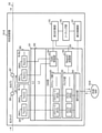
図1は、実施形態に係る光リングネットワークシステム100の一例を示す。
図1の例では、光伝送装置101-A、光伝送装置101-B、光伝送装置101-Cおよび光伝送装置101-Dが、光ファイバで構成されるリング型のネットワーク(光リングネットワーク102)で接続されている。
ここで、光伝送装置101-A、光伝送装置101-B、光伝送装置101-Cおよび光伝送装置101-Dに共通する説明を行う場合は、符号末尾のアルファベットを省略して光伝送装置101と記載する。複数の光伝送装置101のうち、特定の装置を指す場合は、符号末尾にアルファベットを付加して、例えば光伝送装置101-Aと記載する。外部NW(NetWork)103-A、外部NW103-B、外部NW103-Cおよび外部NW103-Dについても同様に記載する。
各光伝送装置101には、外部NW103がそれぞれ接続され、光リングネットワーク102を介して、これらの外部NW103間での通信が可能である。ここで、外部NW103から受信するデータは、波長多重される複数の波長の光信号に振り分けられ、通信先の光伝送装置101に送信される。
外部NW103は、上述の光リングネットワークシステム100に接続されるNWであり、NW装置などが接続される。
ここで、実施形態に係る光リングネットワークシステム100は、光信号を波長多重して通信を行う。例えば、図1では、λ1-nのn個(nは正の整数)の波長の光信号が波長多重されている。
さらに、光リングネットワークシステム100は、バースト光リングネットワーク技術を用いる。これにより、複数の光伝送装置101は、波長ごとに光信号を時分割多重(光TDMA(Time Division Multiple Access))して、光リングネットワーク102上で通信を行う。
図1において、複数の光伝送装置101のうち、1台の光伝送装置101が親装置(親の通信装置に対応)、他の光伝送装置101が子装置(子の通信装置に対応)として動作する。親装置は、波長ごとに全装置の光信号の送信タイミングなどを制御する。ここで、初期状態における親装置は予め決められており、例えば光伝送装置101-Aが親装置である場合、光伝送装置101-B、光伝送装置101-Cおよび光伝送装置101-Dは子装置となる。なお、子装置は、親装置が故障した場合に、子装置のいずれかが新たな親装置として動作する機能を有してもよい。
図1において、子装置の光伝送装置101(例えば光伝送装置101-B)は、親装置の光伝送装置101(例えば光伝送装置101-A)に送信帯域を要求するためのReportメッセージを送信する(送信要求量)。そして、親装置の光伝送装置101(例えば光伝送装置101-A)は、子装置の光伝送装置101(例えば光伝送装置101-B)に送信帯域を割り当てるためのGateメッセージを送信する(送信許可量)。
そして、子装置の光伝送装置101は、波長ごとに親装置に送信した送信要求量と、親装置から受信した送信許可量とに基づいて、波長ごとの帯域利用率を推定する。子装置の光伝送装置101は、波長間の帯域利用率が平準化するように、外部NW103から受信するデータを各波長に対応するバッファに振り分ける。
このようにして、実施形態に係る子装置の光伝送装置101は、送信要求量と送信許可量とに基づいて波長ごとの帯域利用率を推定し、波長間の帯域利用率が平準化するように、各波長のバッファに振り分けるデータ量の重みづけを行う。これにより、実施形態に係る光リングネットワークシステム100は、帯域利用率の低い波長のバッファに優先してデータを振り分けることができ、波長間の帯域利用率の平準化を図り、システム全体の通信効率を向上することができる。
(光伝送装置101の構成例)
図1で説明した4つの光伝送装置101は、親装置と子装置の両方の機能を有し、いずれか一方の機能を選択して親装置または子装置として動作できる。例えば親装置の機能が選択された場合は、光伝送装置101-Aは親装置として動作し、子装置の機能が選択された場合は、光伝送装置101-Aは子装置として動作する。
図1で説明した4つの光伝送装置101は、親装置と子装置の両方の機能を有し、いずれか一方の機能を選択して親装置または子装置として動作できる。例えば親装置の機能が選択された場合は、光伝送装置101-Aは親装置として動作し、子装置の機能が選択された場合は、光伝送装置101-Aは子装置として動作する。
ここで、以降の説明では、光伝送装置101-Aが親装置、光伝送装置101-B、光伝送装置101-Cおよび光伝送装置101-Dが子装置として運用中であるものとする。
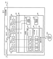
図2は、図1に示す子装置として動作する光伝送装置101-Bの構成例を示す。なお、光伝送装置101-Bと同じ子装置として動作する光伝送装置101-Cおよび光伝送装置101-Dは、光伝送装置101-Bと同様に動作する。
図2において、光伝送装置101-Bは、レイヤ1処理部(L1部)201、レイヤ2処理部(L2部)202、スイッチ部(SW部)203、光送信部(B-Tx部)204、光受信部(B-Rx部)205、光カプラ206、光カプラ207、差分計算部215、ソーティング部216および振分制御部221を有する。
L1部201は、OSI参照モデル第1層(物理層)を処理する機能を有する。
L2部202は、OSI参照モデル第2層(データリンク層)を処理する機能を有する。また、L2部202は、親装置として動作するための機能と子装置として動作するための機能とを有し、いずれかの機能を設定により選択することができる。例えば親装置の光伝送装置101-AのL2部202は親装置として動作し、子装置の光伝送装置101-BのL2部202は子装置として動作する。なお、子装置の場合に、親装置の故障を検知する機能を設け、親装置の故障を検知した場合に、新たな親装置として動作するようにしてもよい。
SW部203は、外部NW103-Bに接続されるL2-SWなどの電気パケットスイッチであり、予め設定されたルールに従い、L2部202と外部NW103-Bとの間のパケット転送を処理する機能を有する。なお、SW部203の構成については、後で詳しく説明する。
B-Tx部204は、光信号を断続的に出力する送信部で、光カプラを介して光ファイバに対して、L1部201から転送された信号を光信号としてバースト的に送信する。また、B-Tx部204は、複数の波長ごとに送信部(Tx)を有する。例えば波長λ1のTx204(1)、波長λ2のTx204(2)、・・・波長λnのTx204(n)(不図示)を有する。例えばTx204(1)は、L1部201から転送された信号を波長λ1の光信号としてバースト的に送信する。
B-Rx部205は、断続的な光信号を受信する受信部で、光カプラを介して、光ファイバから光信号をバースト的に受信し、L1部201に信号を転送する。また、B-Rx部205は、複数の波長ごとに受信部(Rx)を有する。例えば波長λ1のRx205(1)、波長λ2のRx205(2)、・・・波長λnのRx205(n)(不図示)を有する。例えばRx205(1)は、光ファイバから光信号をバースト的に受信し、L1部201に信号を転送する。ここで、B-Tx部204およびB-Rx部205は、通信部に対応する。
光カプラ206および光カプラ207は、入力される光信号のパワーを分岐する機能を有する。
(SW部203の構成例)
図2において、実施形態に係るSW部203の構成例について説明する。SW部203は、スケジューラ部251、バッファ部252および振り分け部253、Gate受信部254およびReport送信部255を有する。
図2において、実施形態に係るSW部203の構成例について説明する。SW部203は、スケジューラ部251、バッファ部252および振り分け部253、Gate受信部254およびReport送信部255を有する。
スケジューラ部251は、波長ごとにスケジューラ261を有し、後述のGate受信部254が親装置から受信するGateメッセージに基づいて、バッファ部252に蓄積されたデータを送信する。具体的には、スケジューラ261は、Gateメッセージにより指定された送信タイミングおよび送信時間で担当する波長のバッファ262に蓄積されたデータをB-Tx部204から送信する。例えば、波長λ1での送信はスケジューラ261(1)、波長λ2での送信はスケジューラ261(2)がそれぞれ対応する。ここで、伝送速度×送信時間=送信許可量であり、子装置は、親装置からGateメッセージで通知される送信タイミングおよび送信時間に基づいて、送信許可量を求めることができる。あるいは、親装置が送信許可量そのものを子装置に通知するようにしてもよい。
バッファ部252は、波長ごとにバッファ262を有し、振り分け部253により各波長に振り分けられたデータを蓄積する。例えば、波長λ1はバッファ262(1)、波長λ2はバッファ262(2)がそれぞれ対応する。ここで、波長ごとのバッファ262に蓄積されているデータ量は、後述のReport送信部255により取得される。
振り分け部253は、外部NW103-Bから入力する送信データを波長ごとのバッファ262に振り分ける。実施形態では、振り分け部253は、外部NW103-Bから入力する送信データを振分制御部221により重みづけされた比率で各波長のバッファ262に振り分ける。ここで、外部NW103-Bから受信するデータの振り分け方法として、例えば重みづけしてデータの振り分けを行うWRR(Weighted RR)などが用いられる。あるいは、WRR以外の他の振り分け方法が用いられてもよい。
Gate受信部254は、親装置の光伝送装置101-Aから子装置に送信されるGateメッセージを受信し、スケジューラ部251および差分計算部215に出力する。ここで、親装置は、波長ごとにGateメッセージを送信してもよいし、複数の波長のそれぞれのGateメッセージを1つのGateメッセージで送信してもよい。なお、Gateメッセージは、スケジューラ部251および差分計算部215に出力される。
Report送信部255は、波長ごとのバッファ262に蓄積されているデータ量を取得し、送信要求量としてReportメッセージにより親装置に通知するとともに、差分計算部215に出力する。なお、Report送信部255は、波長ごとにReportメッセージを親装置に送信してもよいし、複数の波長のそれぞれのReportメッセージを1つのReportメッセージで親装置に送信してもよい。Reportメッセージは、バッファ部252およびスケジューラ部251を介して親装置に送信される。
差分計算部215は、波長ごとに親装置に送信したReportメッセージの送信要求量と、親装置から受信したGateメッセージの送信許可量との差分Δを計算する(式(1))。
差分Δ=送信要求量-送信許可量 …(1)
ここで、例えば波長λ1の差分Δ1、波長λ2の差分Δ2、波長λ3の差分Δ3とする3つの波長を使用する場合、波長ごとの差分Δについて、波長順に下記のようなリストの作成が可能である。
(波長) (差分)
λ1 Δ1
λ2 Δ2
λ3 Δ3
λ1 Δ1
λ2 Δ2
λ3 Δ3
ソーティング部216は、差分計算部215で計算した差分Δの大きさに基づいてリストを並び替える機能を有する。例えば、上記リストにおいて、差分Δの大きさがΔ3>Δ2>Δ1の関係であったと仮定する。この場合、ソーティング部216は、波長順のリストを差分Δの大きい方から降順に下記のように並べ替える。
(波長) (差分)
λ3 Δ3(大)
λ2 Δ2(中)
λ1 Δ1(小)
λ3 Δ3(大)
λ2 Δ2(中)
λ1 Δ1(小)
ここで、差分Δが大きい波長は、送信要求量に対して十分な送信許可量が割り当てられておらず、当該波長のバッファ262に多くのデータが溜まっている状態であり、差分Δが小さい波長よりも帯域利用率が低い。つまり、差分Δが大きい波長ほど帯域利用率が低く、差分Δが小さい波長ほど帯域利用率が高くなる。
振分制御部221は、ソーティング部216が並び替えた順序に従い、振り分け部253が外部NW103から受信するデータを波長ごとのバッファ262に振り分けるときの重みづけを行う。重みづけは、差分Δが小さい(帯域利用率が高い)波長に軽く、差分Δが大きい(帯域利用率が低い)波長に重くする。下記の例では、重み係数の合計は1として、差分Δが一番大きい波長λ3の重み係数が0.6、二番目に大きい波長λ2の重み係数が0.3、差分Δが一番小さい波長λ1の重み係数が0.1のように、それぞれ重みづけが行われる。
(波長) (差分) (重み係数)
λ3 Δ3 0.6
λ2 Δ2 0.3
λ1 Δ1 0.1
λ3 Δ3 0.6
λ2 Δ2 0.3
λ1 Δ1 0.1
ここで、上記の例では、外部NW103から受信するデータは、例えば6パケット:3パケット:1パケットの比率で、それぞれ波長λ3、λ2、λ1の各バッファ262に振り分けられる。
このようにして、子装置として動作する光伝送装置101は、送信要求量と送信許可量とに基づいて波長ごとの帯域利用率を推定し、波長間の帯域利用率が平準化されるように、各波長のバッファ262に振り分けるデータ量の重みづけを行う。これにより、帯域利用率が高い波長のバッファ262に振り分けるデータ量が減少し、帯域利用率が低い波長のバッファ262に振り分けるデータ量が増加するので、波長間の帯域利用率が平準化され、システム全体の通信効率が向上する。
なお、上述の実施形態では、子装置として動作する光伝送装置101の場合について説明したが、親装置として動作する光伝送装置101への適用も可能である。この場合、親装置は、波長ごとに自装置のバッファに蓄積されたデータ量と自装置に割り当てる送信許可量との差分Δを計算して、自装置に接続される外部NW103から受信するデータを重みづけして波長ごとにバッファに振り分ける。
(データ振り分けの重みづけ処理)
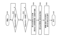
図3は、子装置として動作する光伝送装置101におけるデータ振り分けの重みづけ処理例を示す。ここで、図3の処理は、例えば図2で説明した子装置の光伝送装置101-Bにおける差分計算部215、ソーティング部216、振分制御部221、Gate受信部254およびReport送信部255などにより実行される。なお、図3で説明する処理に対応するプログラムをコンピュータもしくはFPGA(Field Programmable Gate Array)などの集積回路で実行するようにしてもよい。また、プログラムは、記憶媒体に記録して提供されてもよいし、ネットワークを通して提供されてもよい。
図3は、子装置として動作する光伝送装置101におけるデータ振り分けの重みづけ処理例を示す。ここで、図3の処理は、例えば図2で説明した子装置の光伝送装置101-Bにおける差分計算部215、ソーティング部216、振分制御部221、Gate受信部254およびReport送信部255などにより実行される。なお、図3で説明する処理に対応するプログラムをコンピュータもしくはFPGA(Field Programmable Gate Array)などの集積回路で実行するようにしてもよい。また、プログラムは、記憶媒体に記録して提供されてもよいし、ネットワークを通して提供されてもよい。
ステップS101において、子装置として動作中の光伝送装置101は、外部NW103から受信するデータを振り分けるときに重みづけを行う処理を開始する。
ステップS102において、Report送信部255は、バッファ262に蓄積されている送信予定のデータ量(送信要求量)を通知して送信帯域を要求するためのReportメッセージを親装置に送信する。Reportメッセージは、予め決められた送信タイミングで親装置に送信されるので、送信タイミングになるまで待機する。Reportメッセージの送信後、ステップS103の処理に進む。
ステップS103において、Gate受信部254は、親装置から各子装置に送信帯域(送信許可量)を通知するためのGateメッセージを受信したか否かを判別する。Gateメッセージを受信した場合(Y)は、ステップS104の処理に進み、Gateメッセージを受信していない場合(N)は、Gateメッセージを受信するまでステップS103で待機する。
ステップS104において、差分計算部215は、ステップS102で親装置に送信した送信要求量と、ステップS103で親装置から受信した送信許可量とに基づいて、先述の式(1)で説明したように、差分Δを波長ごとに計算する。
ステップS105において、ソーティング部216は、波長順の差分Δのリストを差分Δの大きい方から降順に並べ替える。
ステップS106において、振分制御部221は、ステップS105で並び替えた順序に従い、振り分け部253に対して、外部NW103から受信するデータを波長ごとのバッファ262に振り分けるときの重みづけを決定する。そして、振分制御部221は、決定した重みづけに基づいて、外部NW103から受信するデータを波長ごとのバッファ262に振り分けるように、振り分け部253に指令する。
ステップS107において、子装置として動作中の光伝送装置101は、外部NW103から受信するデータを振り分けるときに重みづけを行う処理を終了する。
なお、光伝送装置101が稼働している間、ステップS102からステップS106までの処理が繰り返し実行されており、差分Δの変化に伴って重みづけの変更が行われる。
ここで、帯域利用率と差分Δの関係について、例えば送信要求量が100、送信許可量が80の場合の帯域利用率は80%であり、差分Δは20である。同様に、送信要求量が100、送信許可量が20の場合の帯域利用率は20%であり、差分Δは80である。つまり、差分Δが大きい場合の帯域利用率は低く、差分Δが小さい場合の帯域利用率は高くなる。そこで、実施形態に係る光伝送装置101は、波長間の帯域利用率の平準化を図るため、帯域利用率の低い波長ほど重みを大きくし、帯域利用率の高い波長ほど重みを小さくする。
このように、実施形態に係る子装置として動作する光伝送装置101は、波長ごとに送信要求量と送信許可量との差分Δを計算して、差分Δの大きさに基づいて外部NW103から受信するデータを重みづけし、波長ごとのバッファ262に振り分ける。これにより、差分Δが大きい(帯域利用率が低い)波長のバッファ262へのデータの振り分けが優先され、差分Δが小さい(帯域利用率が高い)波長のバッファ262に振り分けられるデータ量が減少する。この結果、波長間の帯域利用率が平準化され、システム全体の通信効率が向上する。
[比較例]
図4は、比較例の光リングネットワークシステム800を示す。なお、図4において、図1と同符号のブロックは図1と同様に動作する。
図4は、比較例の光リングネットワークシステム800を示す。なお、図4において、図1と同符号のブロックは図1と同様に動作する。
図4の比較例では、光伝送装置801-A、光伝送装置801-B、光伝送装置801-Cおよび光伝送装置801-Dが、光リングネットワーク102で接続されている。また、各光伝送装置801には、外部NW103がそれぞれ接続されている。ここで、波長多重される光リングネットワーク102および外部NW103は、図1で説明した実施形態の光リングネットワークシステム100と同じである。
比較例の光リングネットワークシステム800は、図1の光リングネットワークシステム100と同様に、波長ごとに光信号を時分割多重するバースト光リングネットワークシステムであり、動的に帯域を割り当てることができる。
比較例の光リングネットワークシステム800では、波長ごとの帯域利用率に関係なく、光伝送装置801が外部NW103から受信するデータを波長ごとのバッファに振り分けるため、通信効率に無駄な部分が生じる可能性がある。例えば波長λ1の帯域利用率が波長λ2の帯域利用率よりも高い場合でも、外部NW103から受信するデータが波長λ1のバッファと波長λ2のバッファとに振り分けられるので、波長λ2よりも帯域利用率が高い波長λ1の負荷が大きくなるという問題が生じる。
これに対して、実施形態に係る光リングネットワークシステム100では、光伝送装置101が帯域利用率を推定し、外部NW103から受信するデータを波長ごとのバッファに振り分けるときの重み付けを決定する。例えば波長λ1の帯域利用率が波長λ2の帯域利用率よりも高い場合、外部NW103から受信するデータが帯域利用率の低い波長λ2のバッファに多く振り分けられるように重み付けする。これにより、波長λ1と波長λ2の帯域利用率が平準化されるので、システム全体の通信効率が向上する。
図5は、図4に示す子装置として動作する比較例の光伝送装置801-Bの構成を示す。なお、光伝送装置801-Cおよび光伝送装置801-Dについても光伝送装置801-Bと同様に動作する。ここで、図4において、光伝送装置801-Aが親装置、光伝送装置801-B、光伝送装置801-Cおよび光伝送装置801-Dが子装置として運用中であるものとする。そして、子装置の光伝送装置801-Bは、図2で説明した子装置の光伝送装置101-Bと同様に、親装置との間でReportメッセージおよびGateメッセージを送受信する。そして、子装置の光伝送装置801-Bは、親装置からGateメッセージで通知された送信許可量で各波長のバッファに蓄積されたデータを送信する。
図5において、光伝送装置801-Bは、L1部901、L2部902、SW部903、B-Tx部904、B-Rx部905、光カプラ906および光カプラ907を有する。ここで、光伝送装置801-Bの基本的な機能は、図2で説明した実施形態に係る光伝送装置101-BのL1部201、L2部202、SW部203、B-Tx部204、B-Rx部205、光カプラ206および光カプラ207と同じである。
実施形態に係る光伝送装置101-Bと異なる部分は、以下の通りである。実施形態に係る光伝送装置101-Bには、差分計算部215、ソーティング部216および振分制御部221があるが、比較例の光伝送装置801-Bにはない。このため、SW部903の振り分け部953、Gate受信部954およびReport送信部955の動作が図2の実施形態に係るSW部203と少し異なる。
振り分け部953は、外部NW103-Bから入力する送信データをバッファ部952の波長ごとのバッファ962に順番に振り分けるだけである。これに対して、図2の実施形態では、振り分け部253は、振分制御部221の指令される比率で外部NW103-Bから入力する送信データを重みづけし、波長ごとのバッファ262に振り分ける。
Gate受信部954は、波長ごとに親装置が子装置に送信するGateメッセージを受信して、Gateメッセージで通知される送信タイミングおよび送信時間をスケジューラ部251に出力する。
Report送信部955は、波長ごとのバッファ262に蓄積されているデータ量を読み取り、波長ごとのデータ量を送信要求量とするReportメッセージを親装置に送信する。
このように、比較例の光伝送装置801-Bは、波長ごとのバッファ962のデータ量をReportメッセージで親装置に通知し、親装置から受信するGateメッセージに基づいて各波長のバッファ962に蓄積されたデータを送信するだけである。このため、各波長のバッファ962には、波長ごとの帯域利用率に関係なく、外部NW103-Bから受信するデータが振り分けられるため、波長間の帯域利用率が異なる場合、通信効率に無駄が生じるという問題がある。
これに対して、図1から図3で説明した実施形態に係る光リングネットワークシステム100では、子装置として動作する光伝送装置101が送信要求量と送信許可量とに基づいて波長ごとの帯域利用率を推定する。そして、光伝送装置101は、波長間の帯域利用率が平準化されるように、各波長のバッファ262にデータを振り分けるときの重み付けを行うので、システム全体の通信効率が向上する。
以上、説明したように、本発明に係る通信装置、通信方法、通信システムおよび通信プログラムは、波長間の帯域利用率の平準化を図り、システム全体の通信効率を向上することができる。
100,800・・・光リングネットワークシステム;101,801・・・光伝送装置;102・・・光リングネットワーク;103・・・外部NW;201,901・・・L1部;202,902・・・L2部;203,903・・・SW部;204,904・・・B-Tx部;205,905・・・B-Rx部;206,207,906,907・・・光カプラ;215・・・差分計算部;216・・・ソーティング部;221・・・振分制御部;251,951・・・スケジューラ部;252,952・・・バッファ部;253,953・・・振り分け部;254,954・・・Gate受信部;255,955・・・Report送信部;261,961・・・スケジューラ;262,962・・・バッファ
Claims (7)
- 波長多重された光リングネットワークに接続され、波長ごとに光信号を時分割多重して通信を行うとともに、親の通信装置に送信帯域を要求するための送信要求量を送信し、親の通信装置から送信帯域を割り当てるための送信許可量を受信する通信部と、
前記送信要求量と前記送信許可量とに基づいて、波長ごとの帯域利用率を推定し、波長間の帯域利用率が平準化するように各波長にデータを振り分ける制御部と
を有することを特徴とする通信装置。 - 請求項1に記載の通信装置において、
前記制御部は、
前記送信要求量と前記送信許可量との差分を波長ごとに計算する差分計算部と、
波長ごとの前記差分のリストを前記差分が大きい順に並べ替えるソーティング部と、
前記ソーティング部が並べ替えた前記差分が大きい順に各波長のバッファへ振り分けるデータ量の重みづけを行い、各波長のバッファにデータを振り分ける振り分け制御部と
を有することを特徴とする通信装置。 - 親の通信装置と子の通信装置とが接続される波長多重された光リングネットワークを介して、波長ごとに光信号を時分割多重して通信を行う通信システムで用いる通信方法であって、
前記親の通信装置は、複数の前記子の通信装置から送信帯域を要求するための送信要求量を受信し、それぞれの前記子の通信装置に送信帯域を割り当てるための送信許可量を送信し、
前記子の通信装置は、前記親の通信装置に送信する前記送信要求量と、前記親の通信装置から受信する前記送信許可量とに基づいて、波長ごとの帯域利用率を推定し、波長間の帯域利用率が平準化するように各波長にデータを振り分ける
ことを特徴とする通信方法。 - 請求項3に記載の通信方法において、
前記子の通信装置は、
前記送信要求量と前記送信許可量との差分を波長ごとに計算し、
波長ごとの前記差分のリストを前記差分が大きい順に並べ替えを行い、
並べ替えた前記差分が大きい順に各波長のバッファへ振り分けるデータ量の重みづけを行い、各波長のバッファにデータを振り分ける
ことを特徴とする通信方法。 - 親の通信装置と子の通信装置とが接続される波長多重された光リングネットワークを介して、波長ごとに光信号を時分割多重して通信を行う通信システムにおいて、
前記親の通信装置は、複数の前記子の通信装置から送信帯域を要求するための送信要求量を受信し、それぞれの前記子の通信装置に送信帯域を割り当てるための送信許可量を送信し、
前記子の通信装置は、前記親の通信装置に送信する前記送信要求量と、前記親の通信装置から受信する前記送信許可量とに基づいて、波長ごとの帯域利用率を推定し、波長間の帯域利用率が平準化するように各波長にデータを振り分ける
ことを特徴とする通信システム。 - 請求項5に記載の通信システムにおいて、
前記子の通信装置は、
前記送信要求量と前記送信許可量との差分を波長ごとに計算し、
波長ごとの前記差分のリストを前記差分が大きい順に並べ替えを行い、
並べ替えた前記差分が大きい順に各波長のバッファへ振り分けるデータ量の重みづけを行い、各波長のバッファにデータを振り分ける
ことを特徴とする通信システム。 - 請求項1または請求項2に記載の前記通信装置の前記制御部が行う処理をコンピュータもしくは集積回路に実行させることを特徴とする通信プログラム。
Priority Applications (3)
| Application Number | Priority Date | Filing Date | Title |
|---|---|---|---|
| JP2022536054A JPWO2022013988A1 (ja) | 2020-07-15 | 2020-07-15 | |
| US18/015,680 US20230318730A1 (en) | 2020-07-15 | 2020-07-15 | Communication device, communication method, communication system and communication program |
| PCT/JP2020/027564 WO2022013988A1 (ja) | 2020-07-15 | 2020-07-15 | 通信装置、通信方法、通信システムおよび通信プログラム |
Applications Claiming Priority (1)
| Application Number | Priority Date | Filing Date | Title |
|---|---|---|---|
| PCT/JP2020/027564 WO2022013988A1 (ja) | 2020-07-15 | 2020-07-15 | 通信装置、通信方法、通信システムおよび通信プログラム |
Publications (1)
| Publication Number | Publication Date |
|---|---|
| WO2022013988A1 true WO2022013988A1 (ja) | 2022-01-20 |
Family
ID=79554596
Family Applications (1)
| Application Number | Title | Priority Date | Filing Date |
|---|---|---|---|
| PCT/JP2020/027564 Ceased WO2022013988A1 (ja) | 2020-07-15 | 2020-07-15 | 通信装置、通信方法、通信システムおよび通信プログラム |
Country Status (3)
| Country | Link |
|---|---|
| US (1) | US20230318730A1 (ja) |
| JP (1) | JPWO2022013988A1 (ja) |
| WO (1) | WO2022013988A1 (ja) |
Citations (1)
| Publication number | Priority date | Publication date | Assignee | Title |
|---|---|---|---|---|
| JP2007228378A (ja) * | 2006-02-24 | 2007-09-06 | Haneron:Kk | 光波長選択型可変adm装置およびそれを用いた波長多重光通信システム |
Family Cites Families (18)
| Publication number | Priority date | Publication date | Assignee | Title |
|---|---|---|---|---|
| FR2838005B1 (fr) * | 2002-03-28 | 2004-12-24 | Cit Alcatel | Methode dynamique d'insertion de donnees aux noeuds d'un reseau de transmission optique |
| US7009991B2 (en) * | 2002-03-28 | 2006-03-07 | Matisse Networks | Reservation-based media access controller and reservation-based optical network |
| US7483631B2 (en) * | 2002-12-24 | 2009-01-27 | Intel Corporation | Method and apparatus of data and control scheduling in wavelength-division-multiplexed photonic burst-switched networks |
| KR100506209B1 (ko) * | 2003-06-16 | 2005-08-05 | 삼성전자주식회사 | 이더넷 수동 광 가입자망에서 다중 서비스를 고려한 동적대역폭 할당방법 |
| FR2857530B1 (fr) * | 2003-07-11 | 2005-09-23 | Cit Alcatel | Reseau optique en anneau a protocole de remplissage de trous independant du debit |
| JP4188368B2 (ja) * | 2005-09-28 | 2008-11-26 | 韓國電子通信研究院 | イーサネット受動光加入者網(EPON)においてQoS保障のための帯域割当装置及び方法 |
| KR100737523B1 (ko) * | 2005-12-05 | 2007-07-10 | 한국전자통신연구원 | 이더넷 수동 광 가입자망에서 QoS보장을 위한 대역 할당장치 및 방법 |
| US20070147837A1 (en) * | 2005-12-07 | 2007-06-28 | Yoo Jeong J | Method of increasing number of subscribers using time division duplexing technology in wavelength division multiplexing/Ethernet passive optical network system |
| KR100775427B1 (ko) * | 2005-12-12 | 2007-11-12 | 삼성전자주식회사 | Gpon 시스템 및 gpon 시스템에서의 대역 할당 방법 |
| US7706688B2 (en) * | 2006-07-17 | 2010-04-27 | University Of Ottawa | Wavelength reconfigurable optical network |
| EP2375773A1 (en) * | 2010-03-29 | 2011-10-12 | Intune Networks Limited | Random GAP insertion in an optical ring network |
| JP5728274B2 (ja) * | 2011-04-05 | 2015-06-03 | 沖電気工業株式会社 | 動的通信帯域割当方法、動的通信帯域割当プログラム、ponシステム及び局側終端装置 |
| EP2863589B1 (en) * | 2012-06-13 | 2020-03-11 | Nippon Telegraph and Telephone Corporation | Optical network system, optical switch node, master node, and node |
| US9794123B2 (en) * | 2013-02-01 | 2017-10-17 | Nippon Telegraph And Telephone Corporation | Highly reliable path accommodation design apparatus and method |
| US9130691B2 (en) * | 2013-02-25 | 2015-09-08 | Verizon Patent And Licensing Inc. | Optical burst switched network nodes |
| CN104348754B (zh) * | 2013-07-26 | 2019-08-23 | 中兴通讯股份有限公司 | 一种光突发环网的带宽分配方法和装置 |
| JP2017118463A (ja) * | 2015-12-25 | 2017-06-29 | 富士通株式会社 | 光端局装置、通信システム、及び通信制御方法 |
| WO2017138550A1 (ja) * | 2016-02-12 | 2017-08-17 | 日本電気株式会社 | 光ネットワーク制御装置および光パス設定方法 |
-
2020
- 2020-07-15 WO PCT/JP2020/027564 patent/WO2022013988A1/ja not_active Ceased
- 2020-07-15 US US18/015,680 patent/US20230318730A1/en not_active Abandoned
- 2020-07-15 JP JP2022536054A patent/JPWO2022013988A1/ja active Pending
Patent Citations (1)
| Publication number | Priority date | Publication date | Assignee | Title |
|---|---|---|---|---|
| JP2007228378A (ja) * | 2006-02-24 | 2007-09-06 | Haneron:Kk | 光波長選択型可変adm装置およびそれを用いた波長多重光通信システム |
Also Published As
| Publication number | Publication date |
|---|---|
| US20230318730A1 (en) | 2023-10-05 |
| JPWO2022013988A1 (ja) | 2022-01-20 |
Similar Documents
| Publication | Publication Date | Title |
|---|---|---|
| US7751713B2 (en) | Communication network with skew path monitoring and adjustment | |
| JP5669613B2 (ja) | 動的帯域割当方法、光通信ネットワーク及び局側装置 | |
| JP6321985B2 (ja) | 局側装置、及び、通信方法 | |
| JP5725226B1 (ja) | 動的波長割当制御方法及び局側装置 | |
| JP6340143B2 (ja) | 伝送システム及び伝送方法 | |
| CN108141403B (zh) | 中继传输系统、中继传输方法以及中继传输装置 | |
| JP5283592B2 (ja) | 光通信システム、光通信方法、制御装置、プログラム、および記録媒体 | |
| JP2019169804A (ja) | 局側装置及び局側装置制御プログラム | |
| CN107534597B (zh) | 站侧装置以及波长切换方法 | |
| JP6310534B2 (ja) | スケジューラ | |
| US11424847B2 (en) | Time and wavelength division multiplexing | |
| JP5378899B2 (ja) | 光通信システム及び光通信方法 | |
| JP5068781B2 (ja) | 通信システム,局側装置および上位通信装置並びに帯域制御方法 | |
| JP2017175578A (ja) | 光伝送装置及び光波長デフラグ方法 | |
| JP2009535949A (ja) | 通信システムを作動させる方法と、このような方法を実施する通信システム | |
| JP4553238B2 (ja) | 光通信方法、光伝送装置、プログラム、および記録媒体。 | |
| JP5853823B2 (ja) | ネットワークの制御方法 | |
| JP5879776B2 (ja) | 局側装置、光通信ネットワーク、及び電源制御方法 | |
| JP5487055B2 (ja) | Onu、光通信システム及びonuの休止方法 | |
| JP5567748B2 (ja) | 信号を送信ノードから複数の受信ノードに送信する通信システム、ノード、及び方法 | |
| JP6852957B2 (ja) | 加入者側光終端装置 | |
| US20230318730A1 (en) | Communication device, communication method, communication system and communication program | |
| WO2022013986A1 (ja) | 通信装置、通信方法、通信システムおよび通信プログラム | |
| JP2017139643A (ja) | 光アクセスネットワークシステム、局側装置、及びその制御プログラム | |
| JP4553236B2 (ja) | 光通信方法および光伝送装置 |
Legal Events
| Date | Code | Title | Description |
|---|---|---|---|
| 121 | Ep: the epo has been informed by wipo that ep was designated in this application |
Ref document number: 20944917 Country of ref document: EP Kind code of ref document: A1 |
|
| ENP | Entry into the national phase |
Ref document number: 2022536054 Country of ref document: JP Kind code of ref document: A |
|
| NENP | Non-entry into the national phase |
Ref country code: DE |
|
| 122 | Ep: pct application non-entry in european phase |
Ref document number: 20944917 Country of ref document: EP Kind code of ref document: A1 |