WO2022013977A1 - ヒートポンプシステム - Google Patents
ヒートポンプシステム Download PDFInfo
- Publication number
- WO2022013977A1 WO2022013977A1 PCT/JP2020/027525 JP2020027525W WO2022013977A1 WO 2022013977 A1 WO2022013977 A1 WO 2022013977A1 JP 2020027525 W JP2020027525 W JP 2020027525W WO 2022013977 A1 WO2022013977 A1 WO 2022013977A1
- Authority
- WO
- WIPO (PCT)
- Prior art keywords
- heat pump
- heated
- heat
- temperature
- fluid
- Prior art date
- Legal status (The legal status is an assumption and is not a legal conclusion. Google has not performed a legal analysis and makes no representation as to the accuracy of the status listed.)
- Ceased
Links
Images

Classifications
-
- B—PERFORMING OPERATIONS; TRANSPORTING
- B01—PHYSICAL OR CHEMICAL PROCESSES OR APPARATUS IN GENERAL
- B01D—SEPARATION
- B01D61/00—Processes of separation using semi-permeable membranes, e.g. dialysis, osmosis or ultrafiltration; Apparatus, accessories or auxiliary operations specially adapted therefor
- B01D61/02—Reverse osmosis; Hyperfiltration ; Nanofiltration
- B01D61/06—Energy recovery
-
- B—PERFORMING OPERATIONS; TRANSPORTING
- B01—PHYSICAL OR CHEMICAL PROCESSES OR APPARATUS IN GENERAL
- B01D—SEPARATION
- B01D61/00—Processes of separation using semi-permeable membranes, e.g. dialysis, osmosis or ultrafiltration; Apparatus, accessories or auxiliary operations specially adapted therefor
- B01D61/02—Reverse osmosis; Hyperfiltration ; Nanofiltration
- B01D61/12—Controlling or regulating
-
- C—CHEMISTRY; METALLURGY
- C02—TREATMENT OF WATER, WASTE WATER, SEWAGE, OR SLUDGE
- C02F—TREATMENT OF WATER, WASTE WATER, SEWAGE, OR SLUDGE
- C02F1/00—Treatment of water, waste water, or sewage
- C02F1/44—Treatment of water, waste water, or sewage by dialysis, osmosis or reverse osmosis
-
- F—MECHANICAL ENGINEERING; LIGHTING; HEATING; WEAPONS; BLASTING
- F24—HEATING; RANGES; VENTILATING
- F24H—FLUID HEATERS, e.g. WATER OR AIR HEATERS, HAVING HEAT-GENERATING MEANS, e.g. HEAT PUMPS, IN GENERAL
- F24H4/00—Fluid heaters characterised by the use of heat pumps
- F24H4/02—Water heaters
-
- F—MECHANICAL ENGINEERING; LIGHTING; HEATING; WEAPONS; BLASTING
- F25—REFRIGERATION OR COOLING; COMBINED HEATING AND REFRIGERATION SYSTEMS; HEAT PUMP SYSTEMS; MANUFACTURE OR STORAGE OF ICE; LIQUEFACTION SOLIDIFICATION OF GASES
- F25B—REFRIGERATION MACHINES, PLANTS OR SYSTEMS; COMBINED HEATING AND REFRIGERATION SYSTEMS; HEAT PUMP SYSTEMS
- F25B30/00—Heat pumps
- F25B30/02—Heat pumps of the compression type
Definitions
- the present invention relates to a heat pump system that heats a fluid using a heat pump.
- the water supply temperature is set to about 25 ° C. in order to maintain the amount of treated water (increased flux due to decrease in water viscosity and improvement in recovery rate due to increase in silica saturation solubility). It is warming up. Steam, hot water, electric heaters, etc. are used to heat this water supply, which consumes energy.
- Claim 7 of Japanese Patent Application Laid-Open No. 2012-91118 describes that the water supply of the RO device is heated to 23 to 25 ° C. by a heat pump.
- the heat pump automatically stops after a predetermined time (for example, 1 hour) regardless of the load on the heat source side. It has an automatic stop function. Therefore, when the water temperature of the water to be heated becomes equal to or less than the allowable value, the heat pump is stopped, so that the water to be heated cannot be continuously heated by the heat pump.
- This automatic stop function is provided to prevent an excessive load on the compressor of the heat pump and to maintain the life of the heat pump.
- An object of the present invention is to provide a heat pump system capable of efficiently heating a fluid to be heated by a heat pump.
- the heat pump system of the present invention circulates a heat medium between the evaporator and the condenser, and heats the heated fluid in the condenser, and sends and receives the heated fluid from the first tank to the condenser.
- a heat pump system having a line, a return line for sending the fluid to be heated from the condenser to the first tank, and a delivery line for sending the fluid heated from the first tank to a demand destination, the condensation.
- a temperature detecting means for detecting the temperature of the fluid to be heated flowing into the vessel, and a transport line for at least a part of the fluid to be heated from the return line when the temperature detected by the temperature detecting means falls below a predetermined temperature. It is characterized by being provided with a circulation means for supplying to.
- the circulation means includes at least a relay tank provided in the forwarding line, a relay line connecting the forwarding line and the relay tank, and a fluid to be heated from the condenser. It has a switching means for flowing a part of the switching means to the relay line, and a control means for controlling the switching means according to the detection temperature of the temperature detecting means.
- control means controls so that when the detection temperature is lower than the predetermined temperature, the flow rate of the heated fluid flowing through the relay line increases as the difference between the two increases. be.
- the heated fluid is water supply to the RO device.
- a warm medium from a freezing system is supplied as a heat source fluid to the evaporator of the heat pump.
- the refrigerating system includes a refrigerator main body and a heat exchanger into which a refrigerant body from the refrigerator main body is introduced and a hot medium flows out, and the heat exchanger flows out.
- a part of the warm medium is returned to the main body of the refrigerator, the rest is introduced into the evaporator of the heat pump, and the medium cooled by the evaporator is returned to the refrigerant body inflow side of the heat exchanger.
- the temperature of the fluid to be heated flowing into the heat pump is prevented from falling below the permissible value. This makes it possible to continuously and efficiently heat the fluid to be heated by the heat pump.
- the water supply to the RO device can be efficiently heated by a heat pump using a heat medium flowing out from the heat exchanger of the refrigeration system as a heat source.
- FIG. 2 shows a heat pump system according to a reference example, which is a heat pump system that heats the water supply of the RO device with a heat pump, and shows a heat pump system in which the heat source of the heat pump is the exhaust heat of the refrigeration system.
- the raw water to be RO-treated flows from the raw water tank 1 into the raw water tank (first tank) 2, is supplied from the raw water tank 2 to the condenser 13 of the heat pump 10 by the pump 31 and the pipe 32, is heated, and then is the pipe 33. It is returned to the raw water tank 2 via.
- the heated raw water in the raw water tank 2 is sent by a pump 3, passes through a heat exchanger 4 using steam as a heat source, and is supplied to the RO device 6 via a pipe 5.
- the permeated water of the RO device 6 is taken out from the pipe 7 as treated water, and the concentrated water flows out to the pipe 8.
- the type of boiler for supplying steam to the heat exchanger 4 is not particularly limited, and may be any of a small once-through boiler, a water pipe boiler, a round boiler, an exhaust heat boiler, and the like. Although heating by steam is not necessary during normal operation, it is used for heating when the refrigerator main body 21 described later is stopped or when the RO device 6 is started. However, if necessary, the RO water supply may be heated by the heat exchanger 4 even during normal operation.
- the heat pump 10 has a well-known configuration, and a heat medium such as an alternative fron from the evaporator 11 is introduced into the condenser 13 at a high temperature by adiabatic compression by the compressor 12, and the heat medium from the condenser 13 is introduced into the expansion valve 14. It is configured to be introduced into the evaporator 11 via an adiabatic expansion to lower the temperature.
- Raw water is passed through a heat transfer tube 13a provided in the condenser 13 via a pump 31 and a pipe 32, exchanges heat with a high-temperature heat medium to be heated, and then returns to the raw water tank 2 through the pipe 33. ..
- a part of the heat medium flowing out of the heat exchanger 24 of the refrigerating system 20 is introduced into the heat transfer tube 11a provided in the evaporator 11 via the second header 25, the pipe 27, and the pump 27a.
- the refrigerant body whose temperature has been lowered by heat exchange with the low temperature heat medium in the evaporator 11 is returned to the first header 23 via the pipe 28 and is introduced again into the heat exchanger 24.
- the refrigerating system 20 sends the refrigerant body cooled by the refrigerator main body 21 such as the turbo type refrigerator and the absorption type refrigerator from the medium delivery unit 21a of the refrigerator main body 21 to the pipe 22 and the first header 23, and the first header 23.
- the header 23 supplies heat to a heat exchanger 24 such as an air conditioner via a pump 23a, absorbs heat from the surroundings, and cools the surroundings.
- a part of the warm medium that has been heated by absorbing the ambient heat by the heat exchanger 24 returns from the second header 25 to the medium return portion 21b of the refrigerator main body 21 via the pipe 26 and the medium circulation pump 26a. ..
- the rest of the heat medium flowing out of the heat exchanger 24 is circulated from the second header 25 to the heat transfer tube 11a of the evaporator 11 via the pipe 27 and the valve 27a, exchanges heat with the heat pump heat medium, and lowers the temperature. It becomes a refrigerant body, returns from the pipe 28 to the first header 23, joins the refrigerant body from the refrigerator main body 21, and flows into the heat exchanger 24.
- a warm medium flowing out of the heat exchanger 24 is used as the heat source fluid distributed in the heat transfer tube 11a of the evaporator 11 of the heat pump 10. Further, the cooled refrigerant body is returned to the heat exchanger 24 by passing through the heat transfer tube 11a of the evaporator 11 of the heat pump 10.
- the refrigerator main body 21 of the refrigerating system 20 uses cold water from the cooling tower 40 as a low-temperature fluid for cooling.
- the cooling water sprinkled from the sprinkler pipe 41 comes into contact with the air introduced from the louver 43 while flowing down the filler layer 42, and is cooled by the latent heat of evaporation to become cold water, and becomes pit 44 (cooling tower). It is stored in the lower water tank).
- the air containing steam is exhausted into the atmosphere by the fan 48.
- the cold water in the pit 44 is supplied to the refrigerator main body 21 via the pump 45 and the pipe 46, and heat is exchanged to raise the temperature.
- the warming water from the refrigerator main body 21 is returned to the sprinkler pipe 41 via the pipe 47.
- the raw water in the raw water tank 2 is heated by the heat pump 10, then heated from the raw water tank 2 by the heat exchanger 4 as needed, and then to the RO device 6. Be supplied.
- the refrigerating system 20 when the temperature of the raw water flowing into the condenser 13 through the pipe 32 becomes equal to or lower than the allowable value (for example, 16 ° C.) of the heat pump 10, the refrigerating system 20 is loaded for a certain period of time (for example, 16 ° C.) or less. After 1 hour) has elapsed, it has an automatic stop function of automatically stopping in order to prevent an excessive load on the compressor 12 of the heat pump 10. Therefore, when the temperature of the raw water flowing into the condenser 13 is equal to or lower than the allowable value, the heat pump system is stopped by the automatic stop function, so that the RO water supply cannot be heated by the heat pump 10.
- the allowable value for example, 16 ° C.
- the raw water in the raw water tank 2 is sent to the relay tank (second tank) 34 via the pump 33a and the valve 33b.
- the relay tank 34 is provided with a water level sensor (not shown), and the pump 33a and the valve 33b are operated in conjunction with the water level sensor so that the water level in the relay tank 34 is maintained at a predetermined water level.
- the water in the relay tank 34 is sent to the condenser 13 via the pump 31 and the pipe 32, heated by flowing through the heat transfer tube 13a, and flows out to the pipe 33.
- the end of the pipe 33 is connected to the inflow port of the switching valve 37 as the flow path switching means.
- the first outflow port of the switching valve 37 is connected to the relay tank 34 via the pipe 38, and the second outflow port is connected to the raw water tank 2 via the pipe 39.
- the switching valve 37 is a three-way valve type, a two-way type valve may be provided in the pipes 38 and 39.
- a temperature sensor 35 for measuring the inflow water temperature to the condenser 13 is installed in the pipe 32, and this detection signal is input to the valve controller 36.
- Valve controller 36 when the detected temperature T of the temperature sensor 35 is lower than the predetermined temperature T 0 causes communication between the pipe 33 pipe 38, the relay tank through the pipe 38 at least part of the effluent of the condenser 13 Water is sent to 34.
- the pipes 33 and 39 are communicated with each other, and most or all of the outflow water of the condenser 13 is returned to the raw water tank 2.
- the ratio of water sent from the pipe 33 to the relay tank 34 is reduced as the T-T 0 becomes larger, and the preset predetermined temperature TH ( TH > T 0 ) is reached. If so, it is preferable to send the entire amount of water from the pipe 33 to the raw water tank 2.
- T H a slightly higher temperature (e.g., 21 ⁇ 25 ° C.) automatic stop reference temperature (in this case 16 ° C.) or more even in the heat pump 10 is preferred.
- T H -T 0 is preferably about 5 ⁇ 9 °C.
- the capacity of the relay tank 34 is smaller than that of the raw water tank 2, and further, the capacity satisfies the following conditions in which the automatic stop function due to the temperature of the heat pump does not operate.
- V Relay tank capacity (m 3 )
- C p Specific heat of water (Mcal / m 3 )
- TL Automatic stop reference temperature (° C)
- t L Time from automatic stop reference temperature detection to automatic designation operation (hr)
- T min Minimum temperature condition (° C) for make-up water to the heat pump
- Q Heat pump heating capacity (Mcal / h)
- the heating capacity (Q) of the heat pump is 400 Mcal / h
- the relay tank may be omitted.
- the heat pump 10 is automatically stopped because the temperature of the water supplied to the heat transfer tube 13a of the condenser 13 of the heat pump 10 is controlled to be equal to or higher than the reference temperature T 0. It is possible to continuously and stably heat the water supply to the RO device 6 without any problem.
- a warm medium flowing out from the heat exchanger 24 such as an air conditioner installed in the refrigerating system 20 is used, and the refrigerating machine is used.
- the freezing load of the main body 21 can be reduced.
- the steam heat exchanger 4 is used in FIG. 1, a heat exchanger using a heat source other than steam may be installed instead of the steam heat exchanger 4.
- the present invention can also be applied to applications for heating fluids other than RO device water supply.
- the heat source of the heat pump 10 may be a heat source other than the waste heat of the refrigeration system.
Landscapes
- Engineering & Computer Science (AREA)
- Chemical & Material Sciences (AREA)
- Water Supply & Treatment (AREA)
- General Engineering & Computer Science (AREA)
- Mechanical Engineering (AREA)
- Physics & Mathematics (AREA)
- Nanotechnology (AREA)
- Thermal Sciences (AREA)
- Chemical Kinetics & Catalysis (AREA)
- Combustion & Propulsion (AREA)
- Life Sciences & Earth Sciences (AREA)
- Hydrology & Water Resources (AREA)
- Environmental & Geological Engineering (AREA)
- Organic Chemistry (AREA)
- Heat-Pump Type And Storage Water Heaters (AREA)
Abstract
原水は原水タンク2から中継タンク34を経てヒートポンプ10の凝縮器13で加熱された後、原水タンク2に戻り、RO装置6に供給される。ヒートポンプ10の蒸発器11の伝熱チューブ11aには、冷凍システム20の熱交換器24から流出する温媒体の一部が流通される。凝縮器13に供給される原水の温度が所定温度よりも低い場合、凝縮器13で加熱された原水の一部を切替弁37から中継タンク34に循環させる。
Description
本発明は、ヒートポンプを用いて流体を加熱するヒートポンプシステムに関する。
逆浸透膜装置(以下、RO装置ということがある。)にあっては、処理水量維持(水の粘度低下によるフラックス上昇、シリカ飽和溶解度上昇による回収率向上)の為、給水温度を25℃程度に加温している。この給水の加熱には蒸気、温水、電気ヒーターなどが使用され、エネルギーを消費している。
特開2012-91118号公報の請求項7には、RO装置の給水をヒートポンプによって23~25℃に加熱することが記載されている。
ヒートポンプは、凝縮器に流入する被加熱水の水温がヒートポンプの許容値(例えば16℃)以下になった場合、熱源側の負荷にかかわらず所定時間(例えば1時間)経過後に自動的に停止する自動停止機能を有する。このため、被加熱水の水温が許容値以下になる場合には、ヒートポンプが停止するので、被加熱水をヒートポンプで継続して加熱することができない。この自動停止機能は、ヒートポンプの圧縮機への過剰な負荷を防止してヒートポンプの寿命を保持する等のために設けられている。
本発明は、ヒートポンプによって被加熱流体を効率よく加熱することができるヒートポンプシステムを提供することを目的とする。
本発明のヒートポンプシステムは、蒸発器と凝縮器との間を熱媒体を循環させ、該凝縮器において被加熱流体を加熱するヒートポンプと、第1タンクから該凝縮器に被加熱流体を送る往送ラインと、該凝縮器から加熱された被加熱流体を該第1タンクに送る復送ラインと、該第1タンクから加熱された流体を需要先へ送る送出ラインとを有するヒートポンプシステムにおいて、前記凝縮器に流入する被加熱流体の温度を検出する温度検出手段と、該温度検出手段で検出される温度が所定温度を下回るときに前記復送ラインから被加熱流体の少なくとも一部を該往送ラインに供給する循環手段とを備えたことを特徴とするものである。
本発明の一態様では、前記循環手段は、前記往送ラインに設けられた中継タンクと、前記復送ラインと該中継タンクとを接続する中継ラインと、前記凝縮器からの被加熱流体の少なくとも一部を該中継ラインに流す切替手段と、前記温度検出手段の検出温度に応じて該切替手段を制御する制御手段とを有する。
本発明の一態様では、前記制御手段は、前記検出温度が前記所定温度を下回る場合、両者の差が大きくなるほど、前記中継ラインに流す被加熱流体の流量を多くするように制御を行うものである。
本発明の一態様では、前記被加熱流体は、RO装置への給水である。
本発明の一態様では、前記ヒートポンプの前記蒸発器に対し、熱源流体として冷凍システムからの温媒体が供給される。
本発明の一態様では、前記冷凍システムは、冷凍機本体と、該冷凍機本体からの冷媒体が導入され、温媒体が流出する熱交換器とを備えており、該熱交換器から流出する温媒体の一部を該冷凍機本体に戻し、残部を前記ヒートポンプの蒸発器に導入し、該蒸発器で降温した媒体を該熱交換器の冷媒体流入側に戻す。
本発明のヒートポンプシステムによると、ヒートポンプに流入する被加熱流体の温度が許容値を下回ることが防止される。これにより、ヒートポンプによって被加熱流体を継続的に効率よく加熱することが可能となる。
本発明の一態様によると、冷凍システムの熱交換器から流出する温媒体を熱源としたヒートポンプでRO装置への給水を効率よく加熱することができる。
以下、図面を参照して参考例及び実施の形態について説明する。
図2は参考例に係るヒートポンプシステムを示すものであり、RO装置の給水をヒートポンプで加熱するヒートポンプシステムであって、ヒートポンプの熱源を冷凍システムの排熱としたヒートポンプシステムを示している。
RO処理される原水は、配管1から原水タンク(第1タンク)2に流入し、該原水タンク2からポンプ31及び配管32によってヒートポンプ10の凝縮器13に供給され、加熱された後、配管33を介して原水タンク2に戻される。原水タンク2内の加温された原水は、ポンプ3によって送水され、蒸気を熱源とした熱交換器4を通り、配管5を介してRO装置6に供給される。RO装置6の透過水は配管7から処理水として取り出され、濃縮水は配管8へ流出する。
熱交換器4に蒸気を供給するためのボイラの形式は特に限定されるものではなく、小型貫流ボイラ、水管ボイラ、丸ボイラ、排熱ボイラなどのいずれでもよい。なお、通常運転時には蒸気による加温は必要ないが、後述の冷凍機本体21の停止時や、RO装置6の起動時などの加温等に使用する。ただし、必要に応じ、通常運転時においても熱交換器4でRO給水を加熱するようにしてもよい。
ヒートポンプ10は、周知構成のものであり、蒸発器11からの代替フロン等の熱媒体を圧縮機12で断熱圧縮により高温として凝縮器13に導入し、凝縮器13からの熱媒体を膨張弁14を介して蒸発器11に導入し、断熱膨張させて降温させるように構成されている。凝縮器13内に設けられた伝熱チューブ13aに原水がポンプ31及び配管32を介して通水され、高温熱媒体と熱交換して加熱された後、配管33を通って原水タンク2に戻る。
蒸発器11内に設けられた伝熱チューブ11aに、冷凍システム20の熱交換器24から流出した温媒体の一部が第2ヘッダー25、配管27及びポンプ27aを介して導入される。蒸発器11内の低温熱媒体との熱交換により降温した冷媒体は、配管28を介して第1ヘッダー23に戻され、熱交換器24に再度導入される。
冷凍システム20は、ターボ式冷凍機、吸収式冷凍機などの冷凍機本体21で冷却された冷媒体を、冷凍機本体21の媒体送出部21aから配管22、第1ヘッダー23に送り、該第1ヘッダー23からポンプ23aを介して空調機などの熱交換器24に供給し、周囲の熱を吸収させて該周囲を冷却する。熱交換器24で該周囲の熱を吸収して昇温した温媒体の一部は、第2ヘッダー25から配管26及び媒体循環用ポンプ26aを介して冷凍機本体21の媒体戻り部21bに戻る。
熱交換器24から流出した温媒体の残部は、第2ヘッダー25から、配管27、バルブ27aを介して蒸発器11の伝熱チューブ11aに流通され、ヒートポンプ熱媒体と熱交換して降温して冷媒体となり、配管28から第1ヘッダー23に戻り、前記冷凍機本体21からの冷媒体と合流して熱交換器24に流入する。
この参考例では、上述の通り、ヒートポンプ10の蒸発器11の伝熱チューブ11aに流通される熱源流体として、熱交換器24から流出する温媒体を利用している。また、ヒートポンプ10の蒸発器11の伝熱チューブ11aを通ることによって降温した冷媒体を熱交換器24に戻すようにしている。
この冷凍システム20の冷凍機本体21は、冷却用の低温流体として冷却塔40からの冷水を用いている。
この冷却塔40では、散水管41から散水された冷却水が充填材層42を流下する間にルーバ43から導入される空気と接触し、蒸発潜熱により冷却されて冷水となり、ピット44(冷却塔下部水槽)に貯留される。蒸気を含む空気はファン48により大気中に排気される。ピット44の冷水は、ポンプ45、配管46を介して冷凍機本体21に供給され、熱交換して昇温する。冷凍機本体21からの温戻り水が配管47を介して散水管41に返送される。
このように構成された図2のヒートポンプシステムでは、原水タンク2内の原水は、ヒートポンプ10で加熱された後、原水タンク2から必要に応じ熱交換器4で加熱された後、RO装置6に供給される。
この参考例では、配管32を介して凝縮器13に流入する原水の水温が該ヒートポンプ10の許容値(例えば16℃)以下になった場合に、冷凍システム20の負荷にかかわらず一定時間(例えば1時間)経過後は、ヒートポンプ10の圧縮機12への過剰な負荷を防止するために、自動的に停止する自動停止機能を有する。このため、凝縮器13に流入する原水の水温が許容値以下の場合には、自動停止機能によりヒートポンプシステムが停止するので、RO給水をヒートポンプ10で加熱することができない。
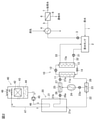
そこで、本形態では、次に説明する図1の通り、凝縮器13に流入する原水の水温を高くする手段を設けることにより、かかる自動停止機能を作動させないようにし、RO給水を常時ヒートポンプで加熱できるようにした。
図1のヒートポンプシステムでは、原水タンク2内の原水をポンプ33a及びバルブ33bを介して中継タンク(第2タンク)34に送水する。中継タンク34には水位センサ(図示略)が設けられており、ポンプ33a及びバルブ33bは、中継タンク34内の水位が所定水位に維持されるように水位センサに連動して操作される。
中継タンク34内の水は、前記ポンプ31及び配管32を介して凝縮器13に送水され、伝熱チューブ13aを流通することにより加熱され、配管33に流出する。
この実施の形態では、配管33の末端は、流路切替手段としての切替弁37の流入ポートに接続されている。切替弁37の第1流出ポートは配管38を介して中継タンク34に接続され、第2流出ポートは配管39を介して原水タンク2に接続されている。なお、切替弁37は三方弁型となっているが、二方型の弁を配管38,39に設けてもよい。
配管32に、凝縮器13への流入水温を測定するための温度センサ35が設置されており、この検出信号がバルブ制御器36に入力されている。バルブ制御器36は、温度センサ35の検出水温Tが所定温度T0よりも低いときには、配管33と配管38を連通させ、凝縮器13の流出水の少なくとも一部を配管38を介して中継タンク34に送水する。検出水温Tが該所定温度T0よりも高いときには、配管33,39を連通させ、凝縮器13の流出水の大部分又は全量を原水タンク2に戻す。
検出水温Tが所定温度T0よりも低い場合、T0-Tが大きくなるほど配管33から中継タンク34に送水する割合を増加させることが好ましい。
検出水温Tが所定温度T0よりも高い場合、T-T0が大きくなるほど配管33から中継タンク34に送水する割合を減少させ、予め設定した所定温度TH(TH>T0)に達したならば、配管33からの水の全量を原水タンク2に送水することが好ましい。
上記所定温度THとしては、ヒートポンプ10の自動停止基準温度(この場合16℃)又はそれよりも若干高い温度(例えば21~25℃)が好適である。TH-T0は5~9℃程度が好ましい。
中継タンク34の容量は、原水タンク2よりも小さい容量であり、更に、ヒートポンプの温度による自動停止機能が動作しない以下の条件を満たす容量であることが好ましい。
V<(tL・Q)/(Cp・(TL-Tmin))
V:中継タンク容量(m3)
Cp:水の比熱(Mcal/m3)
TL:自動停止基準温度(℃)
tL:自動停止基準温度検知から自動指定が動作するまでの時間(hr)
Tmin:ヒートポンプへの補給水の最低温度条件(℃)
Q:ヒートポンプの加熱能力(Mcal/h)
V<(tL・Q)/(Cp・(TL-Tmin))
V:中継タンク容量(m3)
Cp:水の比熱(Mcal/m3)
TL:自動停止基準温度(℃)
tL:自動停止基準温度検知から自動指定が動作するまでの時間(hr)
Tmin:ヒートポンプへの補給水の最低温度条件(℃)
Q:ヒートポンプの加熱能力(Mcal/h)
例えば、ヒートポンプの加熱能力(Q)が400Mcal/hで、0.5時間以内に5℃から16℃まで加温できる最大の中継タンク34の容量は、水の比熱Cp=1Mcal/m3とするとV=(0.5×400)/[1×(16-5)]=18m3となる。
なお、上記条件においては、原水タンクが18m3未満の場合は、中継タンクを省略してもよい。
この実施の形態によると、ヒートポンプ10の凝縮器13の伝熱チューブ13aに供給される水の水温が前記基準温度T0以上となるように制御が行われているため、ヒートポンプ10が自動停止することがなく、RO装置6への給水を継続して安定して加熱することができる。
この実施の形態においても、図2の参考例と同様に、ヒートポンプ10の温熱源として、冷凍システム20に設置された空調機等の熱交換器24から流出する温媒体を用いており、冷凍機本体21の冷凍負荷を低減することができる。
なお、図1では、蒸気式熱交換器4を用いているが、蒸気式熱交換器4の代わりに蒸気以外を熱源とする熱交換器を設置してもよい。本発明は、RO装置給水以外の流体を加熱する用途にも適用することができる。また、ヒートポンプ10の熱源は冷凍システム排熱以外の熱源であってもよい。
本発明を特定の態様を用いて詳細に説明したが、本発明の意図と範囲を離れることなく様々な変更が可能であることは当業者に明らかである。
本出願は、2019年7月8日付で出願された日本特許出願2019-127091に基づいており、その全体が引用により援用される。
本出願は、2019年7月8日付で出願された日本特許出願2019-127091に基づいており、その全体が引用により援用される。
2 原水タンク
4 蒸気式熱交換器
6 RO装置
10 ヒートポンプ
11 蒸発器
12 圧縮機
13 凝縮器
14 膨張弁
20 冷凍システム
21 冷凍機本体
24 熱交換器
34 中継タンク
35 温度センサ
37 切替弁
40 冷却塔
4 蒸気式熱交換器
6 RO装置
10 ヒートポンプ
11 蒸発器
12 圧縮機
13 凝縮器
14 膨張弁
20 冷凍システム
21 冷凍機本体
24 熱交換器
34 中継タンク
35 温度センサ
37 切替弁
40 冷却塔
Claims (6)
- 蒸発器と凝縮器との間を熱媒体を循環させ、該凝縮器において被加熱流体を加熱するヒートポンプと、
第1タンクから該凝縮器に被加熱流体を送る往送ラインと、
該凝縮器から加熱された被加熱流体を該第1タンクに送る復送ラインと、
該第1タンクから加熱された流体を需要先へ送る送出ラインと
を有するヒートポンプシステムにおいて、
前記凝縮器に流入する被加熱流体の温度を検出する温度検出手段と、
該温度検出手段で検出される温度が所定温度を下回るときに前記復送ラインから被加熱流体の少なくとも一部を該往送ラインに供給する循環手段と
を備えたことを特徴とするヒートポンプシステム。 - 前記循環手段は、
前記往送ラインに設けられた中継タンクと、
前記復送ラインと該中継タンクとを接続する中継ラインと、
前記凝縮器からの被加熱流体の少なくとも一部を該中継ラインに流す切替手段と、
前記温度検出手段の検出温度に応じて該切替手段を制御する制御手段と
を有する請求項1のヒートポンプシステム。 - 前記制御手段は、前記検出温度が前記所定温度を下回る場合、両者の差が大きくなるほど、前記中継ラインに流す被加熱流体の流量を多くするように制御を行うものである請求項2のヒートポンプシステム。
- 前記被加熱流体は、RO装置への給水である請求項1~3のいずれかのヒートポンプシステム。
- 前記ヒートポンプの前記蒸発器に対し、熱源流体として冷凍システムからの温媒体が供給される請求項1~4のいずれかのヒートポンプシステム。
- 前記冷凍システムは、冷凍機本体と、該冷凍機本体からの冷媒体が導入され、温媒体が流出する熱交換器とを備えており、
該熱交換器から流出する温媒体の一部を該冷凍機本体に戻し、残部を前記ヒートポンプの蒸発器に導入し、該蒸発器で降温した媒体を該熱交換器の冷媒体流入側に戻すことを特徴とする請求項5のヒートポンプシステム。
Priority Applications (1)
| Application Number | Priority Date | Filing Date | Title |
|---|---|---|---|
| PCT/JP2020/027525 WO2022013977A1 (ja) | 2020-07-15 | 2020-07-15 | ヒートポンプシステム |
Applications Claiming Priority (1)
| Application Number | Priority Date | Filing Date | Title |
|---|---|---|---|
| PCT/JP2020/027525 WO2022013977A1 (ja) | 2020-07-15 | 2020-07-15 | ヒートポンプシステム |
Publications (1)
| Publication Number | Publication Date |
|---|---|
| WO2022013977A1 true WO2022013977A1 (ja) | 2022-01-20 |
Family
ID=79555376
Family Applications (1)
| Application Number | Title | Priority Date | Filing Date |
|---|---|---|---|
| PCT/JP2020/027525 Ceased WO2022013977A1 (ja) | 2020-07-15 | 2020-07-15 | ヒートポンプシステム |
Country Status (1)
| Country | Link |
|---|---|
| WO (1) | WO2022013977A1 (ja) |
Cited By (2)
| Publication number | Priority date | Publication date | Assignee | Title |
|---|---|---|---|---|
| JP7531248B1 (ja) | 2023-11-30 | 2024-08-09 | リバーエレテック株式会社 | 原水と循環冷却水との熱交換システム |
| JP2025129586A (ja) * | 2024-02-26 | 2025-09-05 | 三菱ケミカルアクア・ソリューションズ株式会社 | 水処理装置および水処理方法 |
Citations (4)
| Publication number | Priority date | Publication date | Assignee | Title |
|---|---|---|---|---|
| JP2003139392A (ja) * | 2001-11-05 | 2003-05-14 | Denso Corp | 給湯装置 |
| JP2011242039A (ja) * | 2010-05-17 | 2011-12-01 | Miura Co Ltd | 廃熱回収システムおよびコージェネレーションシステム |
| JP2018027256A (ja) * | 2016-08-19 | 2018-02-22 | 日本ウォーターシステム株式会社 | 水処理装置 |
| WO2020008884A1 (ja) * | 2018-07-06 | 2020-01-09 | 栗田工業株式会社 | 逆浸透処理方法及びシステム |
-
2020
- 2020-07-15 WO PCT/JP2020/027525 patent/WO2022013977A1/ja not_active Ceased
Patent Citations (4)
| Publication number | Priority date | Publication date | Assignee | Title |
|---|---|---|---|---|
| JP2003139392A (ja) * | 2001-11-05 | 2003-05-14 | Denso Corp | 給湯装置 |
| JP2011242039A (ja) * | 2010-05-17 | 2011-12-01 | Miura Co Ltd | 廃熱回収システムおよびコージェネレーションシステム |
| JP2018027256A (ja) * | 2016-08-19 | 2018-02-22 | 日本ウォーターシステム株式会社 | 水処理装置 |
| WO2020008884A1 (ja) * | 2018-07-06 | 2020-01-09 | 栗田工業株式会社 | 逆浸透処理方法及びシステム |
Cited By (3)
| Publication number | Priority date | Publication date | Assignee | Title |
|---|---|---|---|---|
| JP7531248B1 (ja) | 2023-11-30 | 2024-08-09 | リバーエレテック株式会社 | 原水と循環冷却水との熱交換システム |
| JP2025088255A (ja) * | 2023-11-30 | 2025-06-11 | リバーエレテック株式会社 | 原水と循環冷却水との熱交換システム |
| JP2025129586A (ja) * | 2024-02-26 | 2025-09-05 | 三菱ケミカルアクア・ソリューションズ株式会社 | 水処理装置および水処理方法 |
Similar Documents
| Publication | Publication Date | Title |
|---|---|---|
| US7913501B2 (en) | Water-cooled air conditioning system using condenser water regeneration for precise air reheat in dehumidifying mode | |
| JP5855279B2 (ja) | 空気調和装置 | |
| JPH10197088A (ja) | 吸収式冷暖房装置 | |
| US5259202A (en) | Absorption air-conditioning system | |
| JP6689801B2 (ja) | 太陽熱空調システム | |
| JP5955409B2 (ja) | 空気調和装置 | |
| JP6819735B1 (ja) | ヒートポンプシステム | |
| TWI781329B (zh) | 逆滲透處理方法及系統 | |
| JP2009264714A (ja) | ヒートポンプ温水システム | |
| JP3932378B2 (ja) | 空気調和装置 | |
| JP2001099474A (ja) | 空調装置 | |
| JPH062982A (ja) | 吸収冷暖房システムとその制御方法 | |
| JP2004150664A (ja) | 冷却装置 | |
| JP6969223B2 (ja) | ヒートポンプ熱源機 | |
| JP3939214B2 (ja) | ヒートポンプ式給湯装置 | |
| KR100585352B1 (ko) | 흡수 냉동기 | |
| JP2020197340A (ja) | ヒートポンプシステム | |
| JP3594426B2 (ja) | 空調装置 | |
| JP3143251B2 (ja) | 吸収式冷凍機 | |
| JP4183345B2 (ja) | 空調装置 | |
| JP3788391B2 (ja) | 氷蓄熱装置 | |
| JP4519825B2 (ja) | 冷凍サイクル | |
| JP2002156168A (ja) | 吸収式冷凍機 | |
| JP2007127341A (ja) | 吸収ヒートポンプおよび蒸気供給システム | |
| JPH10318585A (ja) | 冷媒循環式空調システム |
Legal Events
| Date | Code | Title | Description |
|---|---|---|---|
| 121 | Ep: the epo has been informed by wipo that ep was designated in this application |
Ref document number: 20945539 Country of ref document: EP Kind code of ref document: A1 |
|
| NENP | Non-entry into the national phase |
Ref country code: DE |
|
| 122 | Ep: pct application non-entry in european phase |
Ref document number: 20945539 Country of ref document: EP Kind code of ref document: A1 |
|
| NENP | Non-entry into the national phase |
Ref country code: JP |