WO2022013965A1 - 浴室乾燥システム - Google Patents
浴室乾燥システム Download PDFInfo
- Publication number
- WO2022013965A1 WO2022013965A1 PCT/JP2020/027472 JP2020027472W WO2022013965A1 WO 2022013965 A1 WO2022013965 A1 WO 2022013965A1 JP 2020027472 W JP2020027472 W JP 2020027472W WO 2022013965 A1 WO2022013965 A1 WO 2022013965A1
- Authority
- WO
- WIPO (PCT)
- Prior art keywords
- bathroom
- temperature
- mobile terminal
- drying system
- dryer
- Prior art date
- Legal status (The legal status is an assumption and is not a legal conclusion. Google has not performed a legal analysis and makes no representation as to the accuracy of the status listed.)
- Ceased
Links
Images

Classifications
-
- H—ELECTRICITY
- H04—ELECTRIC COMMUNICATION TECHNIQUE
- H04Q—SELECTING
- H04Q9/00—Arrangements in telecontrol or telemetry systems for selectively calling a substation from a main station, in which substation desired apparatus is selected for applying a control signal thereto or for obtaining measured values therefrom
Definitions
- the present disclosure relates to a bathroom drying system having a bathroom dryer that can be remotely controlled from a mobile terminal.
- Patent Document 1 has a home network in which a home gateway as an interface and various electric devices are connected to each other, and by connecting the home gateway to an external communication line, a terminal outside the home network and each electric device can be connected.
- a system that enables communication is disclosed.
- each electric device is operated by sending an instruction from a mobile terminal used indoors in which a home network is constructed or a mobile terminal used outdoors to each electric device. can do.
- a bathroom dryer which is one of the electric devices used in a home, receives an instruction from a mobile terminal to start operation, switch operation, or operate. It is possible to perform an operation such as stopping and detecting the temperature in the bathroom.
- the temperature in the bathroom is displayed on the operation unit of the bathroom dryer.
- the operation unit of the bathroom dryer is installed in the bathroom or a dressing room adjacent to the bathroom.
- the temperature detected by the bathroom dryer cannot be confirmed on the mobile terminal. If the user of the bathroom dryer wants to know the temperature in the bathroom, he / she cannot check the temperature in the bathroom at a place away from the bathroom, and he / she needs to go to the place where the operation unit is located and check the display of the operation unit. was there.
- the present disclosure has been made in view of the above, and an object thereof is to obtain a bathroom drying system capable of confirming the temperature in the bathroom at a place away from the bathroom.
- the bathroom drying system can communicate with a bathroom dryer that takes in air from the bathroom and circulates the taken-in air to the bathroom, and a bathroom dryer. Equipped with an information processing device.
- the bathroom dryer has a detection unit that detects the temperature of the air taken in from the bathroom, and a communication unit that transmits temperature information indicating the detected temperature to the information processing apparatus.
- the information processing device holds the received temperature information and transmits the held temperature information.
- the bathroom drying system according to the present disclosure has the effect of being able to check the temperature inside the bathroom at a place away from the bathroom.
- the operation unit 8 is a dedicated operation terminal for operating the bathroom dryer 2.
- the operation unit 8 is connected to the main body unit 7 via wiring.
- the operation unit 8 is installed in the same room as the bathroom 10.
- the operation unit 8 is installed in, for example, a dressing room 11 adjacent to the bathroom 10.
- the operation unit 8 may be installed in a space other than the dressing room 11, or may be installed in the bathroom 10.
- the operation unit 8 is installed at a position where the user can easily operate the bathroom 10.
- the operation unit 8 may be a remote controller.
- the bathroom dryer 2, the wireless LAN adapter 3, and the broadband router 4 constitute a home network system.
- the broadband router 4 is an interface for connecting a home network to the Internet line 9.
- An electric device other than the bathroom dryer 2 may be connected to the home network system.
- the damper 13 is divided into a first air passage for flowing the air taken into the main body 7 to the exhaust duct and a second air passage for flowing the air taken into the main body 7 to the bathroom 10. It is provided.
- the damper 13 adjusts the opening degree of the first air passage and the opening degree of the second air passage by rotational driving.
- the bathroom dryer 2 takes in the air of the bathroom 10 into the main body 7 by driving the blower 12.
- the bathroom dryer 2 blows the air heated by the heater 14 to the bathroom 10 through the second air passage.
- the bathroom dryer 2 sends air from the first air passage to the exhaust duct in the ventilation operation.
- the air taken into the inside of the main body 7 is divided into a first air passage and a second air passage.
- the bathroom dryer 2 sends the air passing through the first air passage to the exhaust duct, and at the same time, blows the air heated by the heater 14 through the second air passage to the bathroom 10.
- the bathroom dryer 2 may blow cool air to the bathroom 10 instead of warm air.
- the control device 15 switches between a heating operation, a ventilation operation, and a drying operation by controlling the damper 13 and the heater 14.
- the temperature sensor 16 which is a detection unit is provided inside the main body unit 7.
- the temperature sensor 16 is arranged in the air passage through which the air from the bathroom 10 to the blower 12 passes.
- the temperature sensor 16 detects the temperature of the bathroom 10 by detecting the temperature of the air taken in from the bathroom 10.
- the motion sensor 17 is provided on the lower surface of the main body 7 located in the bathroom 10. The motion sensor 17 detects the position and movement of a person in the bathroom 10.
- FIG. 3 is a diagram showing a bathroom dryer, a bathroom water heater, and a dressing room heater included in the bathroom drying system according to the first embodiment.
- the water heater 20 and the undressing room heater 30 are electrical devices connected to the home network system.
- the water heater 20 supplies the hot water used in the bathroom 10.
- the water heater 20 performs hot water filling of the bathtub 23 installed in the bathroom 10.
- Hot water beam refers to storing hot water in the bathtub 23 so that the user can take a bath.
- the water heater 20 has a communication unit 21 for the water heater 20 to communicate with an external device of the water heater 20, and an operation unit 22 which is a dedicated operation terminal for operating the water heater 20.
- the communication unit 21 is a wireless LAN adapter similar to the wireless LAN adapter 3.
- the communication unit 21 and the operation unit 22 are installed in the dressing room 11.
- the communication unit 21 and the broadband router 4 are connected to each other via a wireless LAN.
- the undressing room heater 30 heats the undressing room 11.
- the undressing room heater 30 is installed on the ceiling of the undressing room 11.
- the undressing room heater 30 has a blower 33 that generates an air flow, a heater 34 that heats the air, a temperature sensor 35 that detects the temperature, and a motion sensor 36 that detects the location of a person in the undressing room 11.
- the undressing room heater 30 takes in air from the undressing room 11 by driving the blower 33, and blows out the air heated by the heater 34 to the undressing room 11.
- the undressing room heater 30 warms the air taken in from the undressing room 11 and circulates the warm air to the undressing room 11.
- the undressing room heater 30 includes a communication unit 31 for the undressing room heater 30 to communicate with an external device of the undressing room heater 30, and an operation unit 32 which is a dedicated operation terminal for operating the undressing room heater 30. And have.
- the communication unit 31 is a wireless LAN adapter similar to the wireless LAN adapter 3.
- the communication unit 31 and the operation unit 32 are installed in the dressing room 11.
- the communication unit 31 and the broadband router 4 are connected to each other via a wireless LAN.
- the mobile terminal 6 accepts an operation for hot water and an operation for the undressing room heater 30. Further, when the mobile terminal 6 receives the notification indicating the completion of the hot water, the mobile terminal 6 displays the message of the completion of the hot water.
- the bathroom dryer 2, the water heater 20, and the undressing room heater 30 have an operation unit independent of each other and a control adapter independent of each other.
- the operation unit 8 and the control adapter are connected to the control device 15.
- the operation unit 22 and the control adapter are connected to a control device provided in the water heater 20 main body.
- the operation unit 32 and the control adapter are connected to the control device provided in the undressing room heater 30 main body.
- Individual identification of the bathroom dryer 2, the water heater 20, and the undressing room heater 30 on the network is performed by the control adapter. Illustration of each control adapter of the bathroom dryer 2, the water heater 20 and the undressing room heater 30, the control device of the water heater 20, and the control device of the undressing room heater 30 is omitted.
- the water heater 20 starts hot water filling according to the operation of the operation unit 22 by the user. Alternatively, when the user operates the mobile terminal 6, the instruction to start hot water is transmitted to the water heater 20 via the cloud server 5. The water heater 20 starts hot water filling when the communication unit 21 receives an instruction to start hot water filling.
- the bathroom drying system 1 instructs the bathroom dryer 2 to start the heating operation from the cloud server 5.
- the bathroom dryer 2 starts the heating operation when the wireless LAN adapter 3 receives an instruction to start the heating operation.
- the heating of the bathroom 10 may not be completed even if the hot water is completed.
- the bathroom drying system 1 transmits the temperature information indicating the temperature of the bathroom 10 to the mobile terminal 6 together with the notification of the completion of the hot water.
- the user can check the temperature of the bathroom 10 at a place away from the bathroom 10.
- the user can determine that the bathing is waited until the temperature of the bathroom 10 rises.
- the water heater 20 receives an instruction to start hot water from the cloud server 5. In step S1, the water heater 20 starts the hot water beam according to the instruction for starting the hot water beam.
- the bathroom dryer 2 receives the start of the heating operation from the cloud server 5. In step S2, the bathroom dryer 2 starts the heating operation.
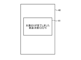
- FIG. 5 is a diagram showing an example of a notification screen displayed on the mobile terminal of the bathroom drying system according to the first embodiment.
- FIG. 5 shows an example of the notification screen 40 displayed in step S13 shown in FIG.
- the notification screen 40 contains a message 41 including a character string of "hot water beam is completed” indicating that the hot water beam is completed and a character string of "room temperature (bathroom) XX ° C" indicating the latest temperature information. Is displayed. From the message 41, the user can confirm that the hot water has been completed and can confirm the current temperature of the bathroom 10.
- the cloud server 5 notifies the mobile terminal 6 that the heating of the bathroom 10 is completed when the temperature of the bathroom 10 reaches a preset temperature after the heating operation by the bathroom dryer 2 is started. You may send it. By such notification, the user can confirm that the heating of the bathroom 10 is completed at a place away from the bathroom 10.
- the bathroom drying system 1 transmits the temperature information to the cloud server 5 by the wireless LAN adapter 3, and transmits the temperature information to the mobile terminal 6 by the cloud server 5.
- the user can confirm the current temperature of the bathroom 10 by the notification screen 40 displayed on the mobile terminal 6.
- the bathroom drying system 1 has an effect that the temperature of the bathroom 10 can be confirmed at a place away from the bathroom 10.
- the bathroom drying system 1 can realize high convenience by automatically transmitting the notification indicating the completion of the hot water filling and the temperature of the bathroom 10 at the time of the completion of the hot water filling to the mobile terminal 6.
- the bathroom dryer 2 stops the heating operation started with the start of the hot water beam when a preset time, for example, one hour has elapsed from the start. As a result, the bathroom dryer 2 prevents the heating operation from being continued more than necessary due to the user forgetting to turn off the heating operation.
- a preset time for example, one hour has elapsed from the start.
- the bathroom dryer 2 prevents the heating operation from being continued more than necessary due to the user forgetting to turn off the heating operation.
- the cloud server 5 transmits a notification for confirming the necessity of the heating operation to the mobile terminal 6.
- the user can confirm that the temperature of the bathroom 10 has dropped at a place away from the bathroom 10.
- the user can cause the bathroom dryer 2 to perform the heating operation again by operating the mobile terminal 6.
- the detection result of the location of the person by the motion sensor 17 is sent to the operation unit 8.
- the operation unit 8 detects that the first bather has started bathing by detecting the position and movement of a person in the bathroom 10 after the hot water is completed. After the start of bathing is detected, the operation unit 8 completes the bathing of the bather when the position and movement of the person in the bathroom 10 are not detected for a preset time, for example, 5 minutes. Is detected.
- the operation unit 8 detects that the bathing by the first bather is completed after the hot water beam is completed, based on the detection result.
- the operation unit 8 transmits a notification indicating that the bather has completed bathing to the cloud server 5.
- the cloud server 5 raises the temperature of the bathroom 10 when the temperature detected by the temperature sensor 16 does not rise to a preset reference value even if the heating operation is continued for a certain period of time or longer.
- Information indicating not to be transmitted is transmitted to the mobile terminal 6.
- the user can know that the temperature of the bathroom 10 does not rise even if the heating operation is continued. In this way, by transmitting information indicating that the temperature of the bathroom 10 does not rise to the mobile terminal 6, the bathroom drying system 1 prompts the user to confirm the status of the bathroom 10.
- the temperature detection result by the temperature sensor 16 is sent to the operation unit 8. If the detection result does not reach the preset reference value even if the heating operation is continued for a certain period of time, for example, one hour or more, the operation unit 8 does not raise the temperature of the bathroom 10 even if the heating operation is performed. judge.
- the bathroom dryer 2 transmits information indicating that the temperature of the bathroom 10 does not rise to the cloud server 5.
- the determination that the temperature of the bathroom 10 does not rise even if the heating operation is performed may be performed by the control device 15 that receives the temperature detection result from the temperature sensor 16. By receiving the temperature information after the hot water is completed, the cloud server 5 may determine that the temperature of the bathroom 10 does not rise.
- the cloud server 5 When the cloud server 5 receives the information indicating that the temperature of the bathroom 10 does not rise, the cloud server 5 transmits the information to the mobile terminal 6. Further, the cloud server 5 transmits the latest temperature information indicating the temperature of the bathroom 10 to the mobile terminal 6.
- FIG. 7 is a diagram showing an example of a notification screen displayed on the mobile terminal of the bathroom drying system according to the third embodiment.
- FIG. 7 shows an example of a notification screen 60 displayed when the mobile terminal 6 receives information indicating that the temperature of the bathroom 10 does not rise and temperature information.
- the character string "bathroom temperature does not rise” indicating that the temperature of the bathroom 10 does not rise
- the character string "please check the bathroom” and the "room temperature (room temperature) indicating the latest temperature information”
- Bathroom A message 61 including the character string " ⁇ °C" is displayed.
- the bathroom drying system 1 also confirms the necessity of the heating operation when the temperature drop of the bathroom 10 is detected after the heating operation is stopped.
- the notification may be sent to the mobile terminal 6.
- each of the above embodiments shows an example of the contents of the present disclosure.
- the configurations of each embodiment can be combined with other known techniques.
- the configurations of the respective embodiments may be appropriately combined. It is possible to omit or change a part of the configuration of each embodiment without departing from the gist of the present disclosure.
- 1 Bathroom drying system 1 Bathroom dryer, 2 Bathroom dryer, 3 Wireless LAN adapter, 4 Broadband router, 5 Cloud server, 6 Mobile terminal, 7 Main unit, 8, 22, 32 Operation unit, 9 Internet line, 10 Bathroom, 11 Dressing room, 12,33 blower, 13 damper, 14,34 heater, 15 control device, 16,35 temperature sensor, 17,36 human sensor, 20 water heater, 21,31 communication unit, 23 bathtub, 30 undressing room heater, 40 , 50, 60 Notification screen, 41, 51, 61 messages.
Landscapes
- Engineering & Computer Science (AREA)
- Computer Networks & Wireless Communication (AREA)
- Central Heating Systems (AREA)
- Selective Calling Equipment (AREA)
- Drying Of Solid Materials (AREA)
- Control Of Washing Machine And Dryer (AREA)
Abstract
浴室乾燥システム(1)は、浴室(10)から空気を取り込み、取り込まれた空気を浴室(10)へ循環させる浴室乾燥機(2)と、浴室乾燥機(2)と通信可能な情報処理装置であるクラウドサーバ(5)とを備える。浴室乾燥機(2)は、浴室(10)から取り込まれた空気の温度を検出する検出部と、検出された温度を示す温度情報を情報処理装置へ送信する通信部である無線LANアダプタ(3)とを有する。情報処理装置は、受信した温度情報を保持し、かつ保持された温度情報を送信する。
Description
本開示は、携帯端末からの遠隔操作が可能な浴室乾燥機を有する浴室乾燥システムに関する。
家庭において使用されるさまざまな電気機器について、携帯端末からの操作を可能としたシステムが知られている。特許文献1には、インタフェースであるホームゲートウェイとさまざまな電気機器とを互いに接続したホームネットワークを有し、ホームゲートウェイを外部通信回線に接続することによって、ホームネットワーク外の端末と各電気機器との通信を可能としたシステムが開示されている。特許文献1にかかるシステムによると、ホームネットワークが構築されている屋内において使用される携帯端末、または屋外において使用される携帯端末からの指示が各電気機器へ送られることによって、各電気機器を操作することができる。
上記特許文献1にかかる従来のシステムによると、家庭において使用される電気機器の1つである浴室乾燥機は、携帯端末からの指示を受信することによって、運転の開始、運転の切り換え、または運転の停止といった動作と、浴室内の温度検出とを行い得る。浴室内の温度は、浴室乾燥機の操作部にて表示される。浴室乾燥機の操作部は、浴室、あるいは浴室に隣接する脱衣室等に設置される。
上記特許文献1にかかる従来のシステムでは、浴室乾燥機によって検出された温度を携帯端末において確認することができない。浴室乾燥機のユーザは、浴室内の温度を知りたい場合、浴室から離れた場所では浴室内の温度を確認することができず、操作部がある場所へ行って操作部の表示を確認する必要があった。
本開示は、上記に鑑みてなされたものであって、浴室から離れた場所において浴室内の温度を確認可能とする浴室乾燥システムを得ることを目的とする。
上述した課題を解決し、目的を達成するために、本開示にかかる浴室乾燥システムは、浴室から空気を取り込み、取り込まれた空気を浴室へ循環させる浴室乾燥機と、浴室乾燥機と通信可能な情報処理装置とを備える。浴室乾燥機は、浴室から取り込まれた空気の温度を検出する検出部と、検出された温度を示す温度情報を情報処理装置へ送信する通信部とを有する。情報処理装置は、受信した温度情報を保持し、かつ保持された温度情報を送信する。
本開示にかかる浴室乾燥システムは、浴室から離れた場所において浴室内の温度を確認することができるという効果を奏する。
以下に、実施の形態にかかる浴室乾燥システムを図面に基づいて詳細に説明する。
実施の形態1.
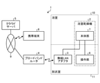
図1は、実施の形態1にかかる浴室乾燥システムの構成を示す図である。実施の形態1にかかる浴室乾燥システム1は、浴室乾燥機2と、無線LAN(Local Area Network)アダプタ3と、ブロードバンドルータ4と、クラウドサーバ5と、携帯端末6とを有する。
図1は、実施の形態1にかかる浴室乾燥システムの構成を示す図である。実施の形態1にかかる浴室乾燥システム1は、浴室乾燥機2と、無線LAN(Local Area Network)アダプタ3と、ブロードバンドルータ4と、クラウドサーバ5と、携帯端末6とを有する。
浴室乾燥機2は、家庭において使用される電気機器の1つである。浴室乾燥機2は、浴室乾燥機2の本体である本体部7と、本体部7への操作を受け付ける操作部8とを有する。本体部7は、浴室10から空気を取り込み、取り込まれた空気を浴室10へ循環させる。また、本体部7は、浴室10から取り込まれた空気を浴室10の外へ排出させる。本体部7は、浴室10の天井に設置される。本体部7は、浴室10の天井裏に設置されている排気ダクトに接続されている。浴室10から排出された空気は、図示しない排気ダクトを通じて屋外へ排出される。なお、浴室乾燥機2が設置されている家屋の中を屋内、当該家屋の外を屋外と称する。
操作部8は、浴室乾燥機2の操作のための専用操作端末である。操作部8は、配線を介して本体部7に接続されている。操作部8は、浴室10と同じ屋内に設置される。操作部8は、例えば、浴室10に隣接する脱衣室11に設置される。なお、操作部8は、脱衣室11以外のスペースに設置されても良く、浴室10に設置されても良い。操作部8は、浴室10を使用する際にユーザが操作し易い位置に設置される。操作部8は、リモートコントローラであっても良い。
浴室乾燥機2は、換気運転と、暖房運転と、乾燥運転とを行うことができる。浴室乾燥機2は、換気運転により、浴室10から取り込まれた空気を浴室10の外へ排出させる。浴室乾燥機2は、暖房運転により、浴室10から取り込まれた空気を温めて浴室10へ温風を循環させる。浴室乾燥機2は、乾燥運転により、浴室10から取り込まれた空気を浴室10の外へ排出すると同時に、浴室10へ温風または涼風を循環させる。
無線LANアダプタ3は、浴室乾燥機2が浴室乾燥機2の外部の機器と通信するための外付けの通信アダプタである。無線LANアダプタ3は、浴室乾燥機2の通信部として機能する。無線LANアダプタ3は、脱衣室11に設置される。無線LANアダプタ3は、本体部7に接続されている。なお、無線LANアダプタ3は、脱衣室11以外のスペースに設置されても良い。無線LANアダプタ3とブロードバンドルータ4とは、無線LANを介して互いに接続される。ブロードバンドルータ4は、屋内に設置される。ブロードバンドルータ4は、インターネット回線9に接続される。
浴室乾燥機2、無線LANアダプタ3およびブロードバンドルータ4は、ホームネットワークシステムを構成する。ブロードバンドルータ4は、インターネット回線9にホームネットワークを接続するためのインタフェースである。なお、ホームネットワークシステムには、浴室乾燥機2以外の電気機器が接続されても良い。
クラウドサーバ5は、情報処理と情報の保持とを担う情報処理装置である。クラウドサーバ5は、ホームネットワークシステムの利用によるサービスを提供する事業者によって運用される。クラウドサーバ5は、ホームネットワークシステムを管理するためのアプリケーションがインストールされたコンピュータシステムである。クラウドサーバ5は、インターネット回線9に接続されている。浴室乾燥機2は、インターネット回線9を介してクラウドサーバ5と通信する。
携帯端末6は、スマートフォンまたはタブレット端末といった、携帯可能な情報端末である。携帯端末6には、ホームネットワークシステムを利用するためのアプリケーションがインストールされている。携帯端末6は、アクセスポイントまたは基地局を介してインターネット回線9に接続される。アクセスポイントおよび基地局の図示は省略する。携帯端末6は、インターネット回線9を介してクラウドサーバ5と通信する。なお、携帯端末6とブロードバンドルータ4とが無線LANを介して互いに接続可能である場合、携帯端末6は、屋内において、ブロードバンドルータ4を介してインターネット回線9へ接続されても良い。携帯端末6は、浴室乾燥機2に対する操作を受け付ける。また、携帯端末6は、浴室乾燥機2の運転についての各種情報を表示する。
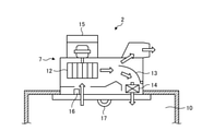
図2は、実施の形態1にかかる浴室乾燥システムが有する浴室乾燥機の構成を示す模式図である。浴室乾燥機2の本体部7は、浴室10の天井に形成されている開口において浴室10から天井裏のほうへ通されて設置される。本体部7は、空気流を発生させる送風機12と、風路を切り換えるためのダンパー13と、空気を温めるヒーター14と、浴室乾燥機2を制御する制御装置15と、温度を検出する温度センサ16と、浴室10における人の所在を検出する人感センサ17とを有する。
ダンパー13は、本体部7の内部へ取り込まれた空気を排気ダクトへ流す第1の風路と、本体部7の内部へ取り込まれた空気を浴室10へ流す第2の風路との分岐に設けられている。ダンパー13は、回転駆動によって、第1の風路の開度と第2の風路の開度とを調節する。
ヒーター14は、第2の風路に配置されている。ヒーター14は、加熱強度を「強」と「弱」の二段階に切り換えて運転可能である。実施の形態1において、ヒーター14は、電気式のヒーターである。ヒーター14は、本体部7の内部へ取り込まれた空気を加熱可能であれば良く、電気式のヒーター以外のヒーターであっても良い。
浴室乾燥機2は、送風機12を駆動することによって浴室10の空気を本体部7の内部へ取り込む。暖房運転において、浴室乾燥機2は、第2の風路を通りヒーター14によって加熱された空気を浴室10へ吹き出す。浴室乾燥機2は、換気運転において、第1の風路から排気ダクトへ空気を送り出す。乾燥運転において、本体部7の内部へ取り込まれた空気は、第1の風路と第2の風路とへ分けられる。乾燥運転において、浴室乾燥機2は、第1の風路を通った空気を排気ダクトへ送り出すとともに、第2の風路を通りヒーター14によって加熱された空気を浴室10へ吹き出す。乾燥運転において、浴室乾燥機2は、温風ではなく涼風を浴室10へ吹き出しても良い。制御装置15は、ダンパー13とヒーター14とを制御することによって、暖房運転と換気運転と乾燥運転との切り換えを行う。
検出部である温度センサ16は、本体部7の内部に設けられている。温度センサ16は、浴室10から送風機12へ向かう空気が通る風路に配置されている。温度センサ16は、浴室10から取り込まれた空気の温度を検出することによって、浴室10の温度を検出する。人感センサ17は、本体部7のうち浴室10内に位置する下面に設けられている。人感センサ17は、浴室10に居る人の位置と動きとを検出する。
操作部8は、浴室乾燥機2の現在の運転状態と、温度センサ16によって検出された温度とを表示する。運転状態とは、換気運転、暖房運転、乾燥運転および運転停止の各状態とする。無線LANアダプタ3は、浴室乾燥機2の運転状態を示す運転状態情報と、温度センサ16によって検出された温度を示す温度情報をクラウドサーバ5へ送信する。クラウドサーバ5は、受信した運転状態情報と受信した温度情報とを保持する。クラウドサーバ5は、保持された運転状態情報と保持された温度情報とを携帯端末6へ送信する。携帯端末6は、受信された運転状態情報と受信された温度情報とを表示する。
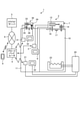
図3は、実施の形態1にかかる浴室乾燥システムが有する浴室乾燥機、浴室の給湯器および脱衣室暖房機を示す図である。給湯器20と脱衣室暖房機30とは、ホームネットワークシステムに接続された電気機器である。
給湯器20は、浴室10において使用される湯を供給する。給湯器20は、浴室10に設置された浴槽23の湯はりを行う。湯はりとは、ユーザが入浴できるように、浴槽23に湯を溜めることを指す。
給湯器20は、給湯器20が給湯器20の外部の機器と通信するための通信部21と、給湯器20の操作のための専用操作端末である操作部22とを有する。通信部21は、無線LANアダプタ3と同様の無線LANアダプタである。通信部21と操作部22とは、脱衣室11に設置される。通信部21とブロードバンドルータ4とは、無線LANを介して互いに接続される。通信部21は、給湯器20による湯はりが完了した場合に、湯はりの完了を示す通知をクラウドサーバ5へ送信する。クラウドサーバ5は、湯はりの完了を示す通知を受信すると、当該通知を携帯端末6へ送信する。
脱衣室暖房機30は、脱衣室11の暖房を行う。脱衣室暖房機30は、脱衣室11の天井に設置される。脱衣室暖房機30は、空気流を発生させる送風機33と、空気を温めるヒーター34と、温度を検出する温度センサ35と、脱衣室11における人の所在を検出する人感センサ36とを有する。脱衣室暖房機30は、送風機33の駆動によって脱衣室11から空気を取り込み、ヒーター34によって加熱された空気を脱衣室11へ吹き出す。脱衣室暖房機30は、脱衣室11から取り込まれた空気を温めて脱衣室11へ温風を循環させる。
温度センサ35は、脱衣室11から送風機33へ取り込まれる空気が通る風路に配置されている。温度センサ35は、脱衣室11から取り込まれた空気の温度を検出することによって、脱衣室11内の温度を検出する。人感センサ36は、脱衣室11に居る人の位置と動きとを検出する。
脱衣室暖房機30は、脱衣室暖房機30が脱衣室暖房機30の外部の機器と通信するための通信部31と、脱衣室暖房機30の操作のための専用操作端末である操作部32とを有する。通信部31は、無線LANアダプタ3と同様の無線LANアダプタである。通信部31と操作部32とは、脱衣室11に設置される。通信部31とブロードバンドルータ4とは、無線LANを介して互いに接続される。
携帯端末6は、湯はりのための操作と、脱衣室暖房機30に対する操作とを受け付ける。また、携帯端末6は、湯はりの完了を示す通知を受信すると、湯はり完了のメッセージを表示する。
実施の形態1において、浴室乾燥機2と給湯器20と脱衣室暖房機30とは、互いに独立した操作部と、互いに独立した制御アダプタとを有する。浴室乾燥機2において、操作部8および制御アダプタは、制御装置15に接続されている。給湯器20において、操作部22および制御アダプタは、給湯器20本体に設けられている制御装置に接続されている。脱衣室暖房機30において、操作部32および制御アダプタは、脱衣室暖房機30本体に設けられている制御装置に接続されている。ネットワーク上における浴室乾燥機2と給湯器20と脱衣室暖房機30との個体識別は、制御アダプタによって行われる。浴室乾燥機2、給湯器20および脱衣室暖房機30の各制御アダプタと、給湯器20の制御装置と、脱衣室暖房機30の制御装置との図示は省略する。
給湯器20は、ユーザによる操作部22の操作に従って湯はりを開始する。または、ユーザが携帯端末6を操作することによって、湯はり開始の指示は、クラウドサーバ5を経由して給湯器20へ送信される。給湯器20は、湯はり開始の指示を通信部21が受信することによって、湯はりを開始する。
携帯端末6の操作によって湯はり開始が指示されると、浴室乾燥システム1は、クラウドサーバ5から浴室乾燥機2へ暖房運転の開始を指示する。浴室乾燥機2は、暖房運転開始の指示を無線LANアダプタ3が受信することによって、暖房運転を開始する。
冬期においては、湯はりが完了しても、浴室10の暖房が完了していない場合がある。実施の形態1では、浴室乾燥システム1は、湯はり完了時において、湯はり完了の通知とともに、浴室10の温度を示す温度情報を携帯端末6へ送信する。ユーザは、携帯端末6の表示を確認することによって、浴室10から離れた場所において浴室10の温度を確認することができる。ユーザは、浴室10の温度が、快適な入浴が可能な温度に達していない場合に、浴室10の温度が上昇するまで入浴を待つといった判断が可能となる。
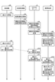
次に、携帯端末6の操作によって湯はりが指示された場合における浴室乾燥システム1の動作について説明する。図4は、実施の形態1にかかる浴室乾燥システムの動作について説明するためのシーケンス図である。図4には、携帯端末6の操作によって湯はりが指示された場合における、浴室乾燥機2、クラウドサーバ5、携帯端末6および給湯器20の動作手順を示している。
給湯器20は、クラウドサーバ5から湯はり開始の指示を受信する。ステップS1において、給湯器20は、湯はり開始の指示に従って湯はりを開始する。浴室乾燥機2は、クラウドサーバ5から暖房運転の開始を受信する。ステップS2において、浴室乾燥機2は、暖房運転を開始する。
ステップS3において、浴室乾燥機2は、運転状態情報と温度情報をクラウドサーバ5へ送信する。ステップS4において、クラウドサーバ5は、運転状態情報と温度情報を受信し、受信された運転状態情報と温度情報を格納する。なお、浴室乾燥機2は、湯はりを開始してから、温度情報を定期的にクラウドサーバ5へ送信する。クラウドサーバ5は、定期的に受信された温度情報を格納する。
ステップS5において、クラウドサーバ5は、運転状態情報を携帯端末6へ送信する。ステップS6において、携帯端末6は、運転状態情報を受信し、受信された運転状態情報を格納する。ステップS7において、携帯端末6は、運転状態情報を表示するための通知画面を生成し、生成された通知画面を表示する。ユーザは、表示された通知画面を見ることによって、浴室乾燥機2の現在の運転状態を確認することができる。
ステップS8において給湯器20による湯はりが完了すると、給湯器20は、ステップS9において、湯はり完了通知をクラウドサーバ5へ送信する。ステップS10において、クラウドサーバ5は、湯はり完了通知を受信する。ステップS11において、クラウドサーバ5は、受信された湯はり完了通知と温度情報を携帯端末6へ送信する。クラウドサーバ5は、湯はり完了通知を受信したときに、クラウドサーバ5に格納されている最新の温度情報を携帯端末6へ送信する。
ステップS12において、携帯端末6は、湯はり完了通知と温度情報を受信する。ステップS13において、携帯端末6は、湯はり完了のメッセージと温度情報を表示するための通知画面を生成し、生成された通知画面を表示する。
図5は、実施の形態1にかかる浴室乾燥システムの携帯端末に表示される通知画面の例を示す図である。図5には、図4に示すステップS13において表示される通知画面40の例を示している。通知画面40には、湯はりが完了したことを示す「お湯はりが完了しました」の文字列と、最新の温度情報を示す「室温(浴室)○○℃」の文字列とを含むメッセージ41が表示される。ユーザは、かかるメッセージ41から、湯はりが完了したことを確認するとともに、浴室10の現在の温度を確認することができる。
なお、クラウドサーバ5は、浴室乾燥機2による暖房運転が開始されてから浴室10の温度があらかじめ設定された温度に達したときに、浴室10の暖房が完了したことの通知を携帯端末6へ送信しても良い。ユーザは、かかる通知により、浴室10の暖房が完了したことを、浴室10から離れた場所において確認することができる。
実施の形態1によると、浴室乾燥システム1は、無線LANアダプタ3によって温度情報をクラウドサーバ5へ送信し、クラウドサーバ5によって温度情報を携帯端末6へ送信する。ユーザは、携帯端末6に表示される通知画面40によって、浴室10の現在の温度を確認することができる。以上により、浴室乾燥システム1は、浴室10から離れた場所において浴室10の温度を確認することができるという効果を奏する。浴室乾燥システム1は、湯はり完了を示す通知と、湯はり完了時の浴室10の温度とを自動的に携帯端末6へ送信することによって、高い利便性を実現できる。
実施の形態2.
実施の形態2では、浴室乾燥システム1は、暖房運転を停止した後における浴室10の温度低下が検知された場合に、暖房運転の要否を確認するための通知を携帯端末6へ送信する。実施の形態2にかかる浴室乾燥システム1は、実施の形態1にかかる浴室乾燥システム1と同様の構成を有する。実施の形態2では、上記の実施の形態1と同一の構成要素には同一の符号を付し、実施の形態1とは異なる動作について主に説明する。
実施の形態2では、浴室乾燥システム1は、暖房運転を停止した後における浴室10の温度低下が検知された場合に、暖房運転の要否を確認するための通知を携帯端末6へ送信する。実施の形態2にかかる浴室乾燥システム1は、実施の形態1にかかる浴室乾燥システム1と同様の構成を有する。実施の形態2では、上記の実施の形態1と同一の構成要素には同一の符号を付し、実施の形態1とは異なる動作について主に説明する。
浴室乾燥機2は、湯はりの開始に伴って開始された暖房運転を、開始からあらかじめ設定された時間、例えば1時間が経過したときに停止する。これにより、浴室乾燥機2は、ユーザが暖房運転を消し忘れることによって暖房運転が必要以上に継続されることを防ぐ。湯はりが完了してから浴室10を利用する入浴者が1人のみである場合、通常、暖房運転を開始してから1時間のうちに入浴は完了すると推定される。湯はりが完了してから複数の入浴者が順次浴室10を利用する場合、全ての入浴者が入浴を完了するまでの時間は、暖房運転を開始してから1時間を超えることがある。この場合、2人目以降の入浴者が浴室10を利用する際に、浴室10の温度が、快適な入浴が可能な温度よりも低下していることがあり得る。
実施の形態2では、クラウドサーバ5は、暖房運転を停止した後における浴室10の温度低下が検知された場合に、暖房運転の要否を確認するための通知を携帯端末6へ送信する。ユーザは、携帯端末6の表示を確認することによって、浴室10の温度が低下したことを、浴室10から離れた場所において確認することができる。ユーザは、浴室10の温度が低下している場合に、携帯端末6への操作によって浴室乾燥機2に暖房運転を再度行わせることができる。
次に、実施の形態2にかかる浴室乾燥システム1の動作について説明する。クラウドサーバ5は、複数の入浴者のうち最初の入浴者の浴室10からの退出が検知された後において浴室10の温度の低下が検知された場合に、携帯端末6へ通知を送信する。
温度センサ16による温度の検出結果は、操作部8へ送られる。操作部8は、かかる検出結果を基に、浴室10の温度を表示する。また、操作部8は、かかる検出結果が、あらかじめ設定された温度よりも低い場合に、浴室10の温度が低下したと判定する。浴室乾燥機2は、このように浴室10の温度低下が検知された場合に、浴室10の温度低下を示す通知をクラウドサーバ5へ送信する。なお、浴室10の温度が低下したか否かの判定は、温度センサ16から温度の検出結果を受けた制御装置15により行われても良い。湯はりが完了した後における温度情報をクラウドサーバ5が受信することによって、クラウドサーバ5が、浴室10の温度が低下したか否かを判定しても良い。
また、人感センサ17による人の所在の検出結果は、操作部8へ送られる。操作部8は、湯はりが完了した後に、浴室10内における人の位置および人の動きを検出することによって、最初の入浴者による入浴が開始されたことを検知する。操作部8は、かかる入浴開始が検知された後に、浴室10内における人の位置および人の動きがあらかじめ設定された時間、例えば5分間検出されなかった場合に、当該入浴者の入浴が完了したと検知する。操作部8は、湯はりが完了した後に最初の入浴者による入浴が完了したことを、かかる検出結果に基づいて検知する。操作部8は、最初の入浴者による入浴が完了したことを検知すると、入浴者の入浴完了を示す通知をクラウドサーバ5へ送信する。
操作部8は、人感センサ17による検出結果と併せて、脱衣室暖房機30からの情報、あるいは給湯器20からの情報を用いることによって、入浴完了を検知しても良い。操作部8は、脱衣室暖房機30の人感センサ36による人の所在の検出結果を、入浴完了の検知に用いても良い。入浴者が入浴する際、脱衣室11内の人感センサ36によって入浴者が5分間程度検出され、その後、浴室10内の人感センサ17によって10分から30分程度入浴者が検出される。さらに、その後、脱衣室11内の人感センサ36によって5分程度入浴者が検出される。入浴を終えた入浴者が脱衣室11から退出することにより、次の入浴者が入浴するまでの間、双方の人感センサ17,36にて入浴者は検出されない。このような双方の人感センサ17,36による一連の検出結果を総合して、操作部8は、入浴完了を検知しても良い。操作部8は、複数の情報に基づいて入浴完了を検知することによって、入浴完了を正確に検知することができる。
なお、操作部8は、給湯器20による給湯量の変化に基づいて、入浴者の入浴が完了したことを検知しても良い。入浴者の入浴が完了したことの検知は、人感センサ17から人の所在の検出結果を受けた制御装置15により行われても良い。人感センサ17から人の所在の検出結果をクラウドサーバ5が受信することによって、クラウドサーバ5が、入浴者の入浴が完了したことを検知しても良い。
最初の入浴者の浴室10からの退出が検知された後において浴室10の温度の低下が検知されると、クラウドサーバ5は、暖房運転の要否を確認するための通知を携帯端末6へ送信する。また、クラウドサーバ5は、浴室10の温度を示す最新の温度情報を携帯端末6へ送信する。
携帯端末6は、暖房運転の要否を確認するための通知と温度情報とを受信する。携帯端末6は、暖房運転の要否を確認するためのメッセージと温度情報を表示するための通知画面を生成し、生成された通知画面を表示する。
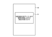
図6は、実施の形態2にかかる浴室乾燥システムの携帯端末に表示される通知画面の例を示す図である。図6には、暖房運転の要否を確認するための通知と温度情報とを携帯端末6が受信した場合において表示される通知画面50の例を示している。通知画面50には、「浴室温度が低下しています」の文字列と、暖房運転の要否を確認するための「暖房を開始しますか」の文字列と、最新の温度情報を示す「室温(浴室)○○℃」の文字列とを含むメッセージ51が表示される。
実施の形態2によると、浴室乾燥システム1は、暖房運転を停止した後における浴室10の温度低下が検知された場合に、暖房運転の要否を確認するための通知を携帯端末6へ送信する。浴室乾燥システム1は、浴室10の温度が低下したことをユーザに通知するとともに、後続の入浴者のための暖房開始をユーザに促すことができる。
実施の形態3.
実施の形態3では、浴室乾燥システム1は、暖房運転が一定時間以上継続されても浴室10の温度があらかじめ設定された基準値にまで上昇しない場合に、浴室10の温度が上昇しないことを示す情報を携帯端末6へ送信する。実施の形態3にかかる浴室乾燥システム1は、実施の形態1または2にかかる浴室乾燥システム1と同様の構成を有する。実施の形態3では、上記の実施の形態1または2と同一の構成要素には同一の符号を付し、実施の形態1または2とは異なる動作について主に説明する。
実施の形態3では、浴室乾燥システム1は、暖房運転が一定時間以上継続されても浴室10の温度があらかじめ設定された基準値にまで上昇しない場合に、浴室10の温度が上昇しないことを示す情報を携帯端末6へ送信する。実施の形態3にかかる浴室乾燥システム1は、実施の形態1または2にかかる浴室乾燥システム1と同様の構成を有する。実施の形態3では、上記の実施の形態1または2と同一の構成要素には同一の符号を付し、実施の形態1または2とは異なる動作について主に説明する。
暖房運転を開始してから時間が経過しても浴室10の温度が上昇しない場合、浴室10に設けられている窓が空いていることによって外気が浴室10に入り込んでいるか、浴室10への出入りのための扉が空いていることによって屋内の空気が浴室10に入り込んでいることが考えられる。または、浴室乾燥機2による暖房運転に異常が生じていることが考えられる。
実施の形態3では、クラウドサーバ5は、暖房運転が一定時間以上継続されても、温度センサ16によって検出された温度があらかじめ設定された基準値にまで上昇しない場合に、浴室10の温度が上昇しないことを示す情報を携帯端末6へ送信する。ユーザは、携帯端末6の表示を確認することによって、暖房運転が継続されても浴室10の温度が上昇しない状況であることを知ることができる。このように、浴室10の温度が上昇しないことを示す情報を携帯端末6へ送信することによって、浴室乾燥システム1は、浴室10の状況確認をユーザに促す。
次に、実施の形態3にかかる浴室乾燥システム1の動作について説明する。温度センサ16による温度の検出結果は、操作部8へ送られる。操作部8は、暖房運転が一定時間、例えば1時間以上継続されても、かかる検出結果が、あらかじめ設定された基準値に到達しない場合、暖房運転を行っても浴室10の温度が上昇しないと判定する。浴室乾燥機2は、浴室10の温度が上昇しないことを示す情報をクラウドサーバ5へ送信する。なお、暖房運転を行っても浴室10の温度が上昇しないことの判定は、温度センサ16から温度の検出結果を受けた制御装置15により行われても良い。湯はりが完了した後における温度情報をクラウドサーバ5が受信することによって、クラウドサーバ5が、浴室10の温度が上昇しないことの判定を行っても良い。
クラウドサーバ5は、浴室10の温度が上昇しないことを示す情報を受信すると、当該情報を携帯端末6へ送信する。また、クラウドサーバ5は、浴室10の温度を示す最新の温度情報を携帯端末6へ送信する。
携帯端末6は、浴室10の温度が上昇しないことを示す情報と温度情報とを受信する。携帯端末6は、浴室10の温度が上昇しないことを示す情報と温度情報とを表示するための通知画面を生成し、生成された通知画面を表示する。
図7は、実施の形態3にかかる浴室乾燥システムの携帯端末に表示される通知画面の例を示す図である。図7には、浴室10の温度が上昇しないことを示す情報と温度情報とを携帯端末6が受信した場合において表示される通知画面60の例を示している。通知画面60には、浴室10の温度が上昇しないことを示す「浴室温度が上昇しません」の文字列と、「浴室をご確認ください」の文字列と、最新の温度情報を示す「室温(浴室)○○℃」の文字列とを含むメッセージ61が表示される。
実施の形態3によると、浴室乾燥システム1は、暖房運転が一定時間以上継続されても、検出された浴室10の温度があらかじめ設定された基準値にまで上昇しない場合に、浴室10の温度が上昇しないことを示す情報を携帯端末6へ送信する。浴室乾燥システム1は、浴室10の温度が上昇しないことをユーザに通知するとともに、浴室10の状況確認をユーザに促すことができる。
浴室乾燥システム1は、実施の形態3においても、実施の形態2と同様に、暖房運転を停止した後において浴室10の温度低下が検知された場合に、暖房運転の要否を確認するための通知を携帯端末6へ送信しても良い。
以上の各実施の形態に示した構成は、本開示の内容の一例を示すものである。各実施の形態の構成は、別の公知の技術と組み合わせることが可能である。各実施の形態の構成同士が適宜組み合わせられても良い。本開示の要旨を逸脱しない範囲で、各実施の形態の構成の一部を省略または変更することが可能である。
1 浴室乾燥システム、2 浴室乾燥機、3 無線LANアダプタ、4 ブロードバンドルータ、5 クラウドサーバ、6 携帯端末、7 本体部、8,22,32 操作部、9 インターネット回線、10 浴室、11 脱衣室、12,33 送風機、13 ダンパー、14,34 ヒーター、15 制御装置、16,35 温度センサ、17,36 人感センサ、20 給湯器、21,31 通信部、23 浴槽、30 脱衣室暖房機、40,50,60 通知画面、41,51,61 メッセージ。
Claims (7)
- 浴室から空気を取り込み、取り込まれた空気を前記浴室へ循環させる浴室乾燥機と、
前記浴室乾燥機と通信可能な情報処理装置と、を備え、
前記浴室乾燥機は、
前記浴室から取り込まれた空気の温度を検出する検出部と、
検出された前記温度を示す温度情報を前記情報処理装置へ送信する通信部と、を有し、
前記情報処理装置は、受信した前記温度情報を保持し、かつ保持された前記温度情報を送信することを特徴とする浴室乾燥システム。 - 前記浴室乾燥機が設置される屋内、または屋外において使用され、前記情報処理装置と通信可能な携帯端末を備え、
前記情報処理装置は、保持された前記温度情報を前記携帯端末へ送信することを特徴とする請求項1に記載の浴室乾燥システム。 - 前記情報処理装置は、前記浴室に設置されている浴槽への湯はりが完了したときに前記湯はりの完了を示す通知を受信し、前記通知を受信したときに最新の前記温度情報を前記携帯端末へ送信することを特徴とする請求項2に記載の浴室乾燥システム。
- 前記浴室乾燥機は、前記浴室から取り込まれた空気を温めて前記浴室へ循環させる暖房運転を行い、
前記情報処理装置は、前記暖房運転を停止した後における前記温度の低下が検知された場合に、前記暖房運転の要否を確認するための通知を前記携帯端末へ送信することを特徴とする請求項2または3に記載の浴室乾燥システム。 - 前記情報処理装置は、前記浴室からの入浴者の退出が検知された後において前記温度の低下が検知された場合に、前記携帯端末へ前記通知を送信することを特徴とする請求項4に記載の浴室乾燥システム。
- 前記浴室乾燥機は、前記浴室から取り込まれた空気を温めて前記浴室へ循環させる暖房運転を行い、
前記暖房運転が一定時間以上継続されても、検出された前記温度があらかじめ設定された基準値にまで上昇しない場合に、前記情報処理装置は、前記浴室の温度が上昇しないことを示す情報を前記携帯端末へ送信することを特徴とする請求項2または3に記載の浴室乾燥システム。 - 前記情報処理装置は、前記暖房運転が開始されてから前記浴室の温度があらかじめ設定された温度に達したときに、前記浴室の暖房が完了したことの通知を前記携帯端末へ送信することを特徴とする請求項4から6のいずれか1つに記載の浴室乾燥システム。
Priority Applications (2)
| Application Number | Priority Date | Filing Date | Title |
|---|---|---|---|
| PCT/JP2020/027472 WO2022013965A1 (ja) | 2020-07-15 | 2020-07-15 | 浴室乾燥システム |
| JP2022536035A JP7361926B2 (ja) | 2020-07-15 | 2020-07-15 | 浴室乾燥システム |
Applications Claiming Priority (1)
| Application Number | Priority Date | Filing Date | Title |
|---|---|---|---|
| PCT/JP2020/027472 WO2022013965A1 (ja) | 2020-07-15 | 2020-07-15 | 浴室乾燥システム |
Publications (1)
| Publication Number | Publication Date |
|---|---|
| WO2022013965A1 true WO2022013965A1 (ja) | 2022-01-20 |
Family
ID=79555748
Family Applications (1)
| Application Number | Title | Priority Date | Filing Date |
|---|---|---|---|
| PCT/JP2020/027472 Ceased WO2022013965A1 (ja) | 2020-07-15 | 2020-07-15 | 浴室乾燥システム |
Country Status (2)
| Country | Link |
|---|---|
| JP (1) | JP7361926B2 (ja) |
| WO (1) | WO2022013965A1 (ja) |
Cited By (1)
| Publication number | Priority date | Publication date | Assignee | Title |
|---|---|---|---|---|
| WO2024252623A1 (ja) * | 2023-06-08 | 2024-12-12 | 三菱電機株式会社 | 浴室暖房乾燥換気システム |
Citations (3)
| Publication number | Priority date | Publication date | Assignee | Title |
|---|---|---|---|---|
| JP2009115367A (ja) * | 2007-11-06 | 2009-05-28 | Panasonic Corp | 浴室換気乾燥装置 |
| JP2016125665A (ja) * | 2014-12-26 | 2016-07-11 | 株式会社ハーマン | 浴室暖房装置 |
| JP2019015444A (ja) * | 2017-07-06 | 2019-01-31 | リンナイ株式会社 | 浴室システム |
Family Cites Families (6)
| Publication number | Priority date | Publication date | Assignee | Title |
|---|---|---|---|---|
| JP6175910B2 (ja) * | 2013-05-31 | 2017-08-09 | マックス株式会社 | 設備機器及び設備機器管理システム |
| JP6655876B2 (ja) * | 2015-01-14 | 2020-03-04 | 大阪瓦斯株式会社 | 浴室乾燥機及び乾燥方法 |
| JP2018063084A (ja) * | 2016-10-14 | 2018-04-19 | 東京瓦斯株式会社 | 情報処理装置、情報処理方法、及びプログラム |
| JP2018113605A (ja) * | 2017-01-12 | 2018-07-19 | 株式会社デンソー | 機器制御装置 |
| JP6832721B2 (ja) * | 2017-01-25 | 2021-02-24 | 日立ジョンソンコントロールズ空調株式会社 | 冷凍サイクル機器の遠隔制御システムおよび家電機器の遠隔制御システム |
| JP6921681B2 (ja) * | 2017-08-10 | 2021-08-18 | リンナイ株式会社 | 暖房システム |
-
2020
- 2020-07-15 JP JP2022536035A patent/JP7361926B2/ja active Active
- 2020-07-15 WO PCT/JP2020/027472 patent/WO2022013965A1/ja not_active Ceased
Patent Citations (3)
| Publication number | Priority date | Publication date | Assignee | Title |
|---|---|---|---|---|
| JP2009115367A (ja) * | 2007-11-06 | 2009-05-28 | Panasonic Corp | 浴室換気乾燥装置 |
| JP2016125665A (ja) * | 2014-12-26 | 2016-07-11 | 株式会社ハーマン | 浴室暖房装置 |
| JP2019015444A (ja) * | 2017-07-06 | 2019-01-31 | リンナイ株式会社 | 浴室システム |
Cited By (1)
| Publication number | Priority date | Publication date | Assignee | Title |
|---|---|---|---|---|
| WO2024252623A1 (ja) * | 2023-06-08 | 2024-12-12 | 三菱電機株式会社 | 浴室暖房乾燥換気システム |
Also Published As
| Publication number | Publication date |
|---|---|
| JP7361926B2 (ja) | 2023-10-16 |
| JPWO2022013965A1 (ja) | 2022-01-20 |
Similar Documents
| Publication | Publication Date | Title |
|---|---|---|
| CN110057033B (zh) | 空调系统及计算机可读取的存储介质 | |
| JP7033703B2 (ja) | 機器管理システム | |
| JP7481643B2 (ja) | 風呂装置、風呂システムおよび安否確認プログラム | |
| JP7035517B2 (ja) | 給湯装置 | |
| JP6209050B2 (ja) | 空気調和機 | |
| JP2018191100A (ja) | 熱源システムの遠隔操作システム | |
| JP7361926B2 (ja) | 浴室乾燥システム | |
| JP7459999B2 (ja) | 浴室換気乾燥暖房機 | |
| JP2021071251A (ja) | 制御装置、空調システム、空調制御方法及びプログラム | |
| JP7394744B2 (ja) | 遠隔操作システム | |
| JP2014236282A (ja) | 設備機器及び設備機器管理システム | |
| JP2021082175A (ja) | 風呂システム | |
| JP7321203B2 (ja) | 通信制御装置及び情報処理システム | |
| JP2021032533A (ja) | 浴室空調システム | |
| JP2002236983A (ja) | 人体異常検出装置 | |
| JP2021071236A (ja) | 浴室空調システム、浴室空調装置、サーバおよびプログラム | |
| JP2012016249A (ja) | 通電制御システム | |
| JP7810749B2 (ja) | ゲートウェイ、情報処理システム、及び制御方法 | |
| KR20180126316A (ko) | 스마트 비데 및 이를 포함하는 제어 시스템 | |
| JP2023159662A (ja) | 浴室換気システム | |
| JP3745236B2 (ja) | 床暖房装置 | |
| JP7400210B2 (ja) | サニタリ空調装置 | |
| JP7341347B2 (ja) | 機器管理システム | |
| JP6046928B2 (ja) | 警報システム | |
| KR101125546B1 (ko) | 공기조화기용 제어장치 |
Legal Events
| Date | Code | Title | Description |
|---|---|---|---|
| 121 | Ep: the epo has been informed by wipo that ep was designated in this application |
Ref document number: 20945366 Country of ref document: EP Kind code of ref document: A1 |
|
| ENP | Entry into the national phase |
Ref document number: 2022536035 Country of ref document: JP Kind code of ref document: A |
|
| NENP | Non-entry into the national phase |
Ref country code: DE |
|
| 122 | Ep: pct application non-entry in european phase |
Ref document number: 20945366 Country of ref document: EP Kind code of ref document: A1 |