WO2022009895A1 - 電制スロットル装置 - Google Patents
電制スロットル装置 Download PDFInfo
- Publication number
- WO2022009895A1 WO2022009895A1 PCT/JP2021/025497 JP2021025497W WO2022009895A1 WO 2022009895 A1 WO2022009895 A1 WO 2022009895A1 JP 2021025497 W JP2021025497 W JP 2021025497W WO 2022009895 A1 WO2022009895 A1 WO 2022009895A1
- Authority
- WO
- WIPO (PCT)
- Prior art keywords
- motor
- throttle
- gear
- electronically controlled
- pigtail
- Prior art date
- Legal status (The legal status is an assumption and is not a legal conclusion. Google has not performed a legal analysis and makes no representation as to the accuracy of the status listed.)
- Ceased
Links
Images

Classifications
-
- F—MECHANICAL ENGINEERING; LIGHTING; HEATING; WEAPONS; BLASTING
- F02—COMBUSTION ENGINES; HOT-GAS OR COMBUSTION-PRODUCT ENGINE PLANTS
- F02D—CONTROLLING COMBUSTION ENGINES
- F02D11/00—Arrangements for, or adaptations to, non-automatic engine control initiation means, e.g. operator initiated
- F02D11/06—Arrangements for, or adaptations to, non-automatic engine control initiation means, e.g. operator initiated characterised by non-mechanical control linkages, e.g. fluid control linkages or by control linkages with power drive or assistance
- F02D11/10—Arrangements for, or adaptations to, non-automatic engine control initiation means, e.g. operator initiated characterised by non-mechanical control linkages, e.g. fluid control linkages or by control linkages with power drive or assistance of the electric type
-
- H—ELECTRICITY
- H02—GENERATION; CONVERSION OR DISTRIBUTION OF ELECTRIC POWER
- H02K—DYNAMO-ELECTRIC MACHINES
- H02K11/00—Structural association of dynamo-electric machines with electric components or with devices for shielding, monitoring or protection
- H02K11/02—Structural association of dynamo-electric machines with electric components or with devices for shielding, monitoring or protection for suppression of electromagnetic interference
-
- H—ELECTRICITY
- H02—GENERATION; CONVERSION OR DISTRIBUTION OF ELECTRIC POWER
- H02K—DYNAMO-ELECTRIC MACHINES
- H02K23/00—DC commutator motors or generators having mechanical commutator; Universal AC/DC commutator motors
- H02K23/66—Structural association with auxiliary electric devices influencing the characteristic of, or controlling, the machine, e.g. with impedances or switches
-
- F—MECHANICAL ENGINEERING; LIGHTING; HEATING; WEAPONS; BLASTING
- F02—COMBUSTION ENGINES; HOT-GAS OR COMBUSTION-PRODUCT ENGINE PLANTS
- F02D—CONTROLLING COMBUSTION ENGINES
- F02D9/00—Controlling engines by throttling air or fuel-and-air induction conduits or exhaust conduits
- F02D9/08—Throttle valves specially adapted therefor; Arrangements of such valves in conduits
- F02D9/10—Throttle valves specially adapted therefor; Arrangements of such valves in conduits having pivotally-mounted flaps
- F02D9/1065—Mechanical control linkage between an actuator and the flap, e.g. including levers, gears, springs, clutches, limit stops of the like
-
- F—MECHANICAL ENGINEERING; LIGHTING; HEATING; WEAPONS; BLASTING
- F02—COMBUSTION ENGINES; HOT-GAS OR COMBUSTION-PRODUCT ENGINE PLANTS
- F02D—CONTROLLING COMBUSTION ENGINES
- F02D9/00—Controlling engines by throttling air or fuel-and-air induction conduits or exhaust conduits
- F02D9/08—Throttle valves specially adapted therefor; Arrangements of such valves in conduits
- F02D9/10—Throttle valves specially adapted therefor; Arrangements of such valves in conduits having pivotally-mounted flaps
- F02D9/107—Manufacturing or mounting details
Definitions
- the present invention relates to an electronically controlled throttle device.
- an inductor is mounted in a motor of an electronically controlled throttle body. Specifically, the middle of the conductive passage from the pair of terminals of the motor connected to the gear cover to the pair of terminals connected to the brush of the motor is divided and exposed, and the pair of ends of each divided conductive passage is exposed. One end and the other end of each of the two inductors are connected to the portion.
- the inductor is intended to reduce the radiation noise by blunting the current fluctuation per unit time by the inductance, but it also aims to suppress the generation of high frequency noise during switching. Therefore, the inductor was selected in a size that can be mounted inside the motor.
- This embodiment relates to a valve body that regulates the flow rate of fluid in an internal combustion engine, an electronically controlled throttle body, a motor-driven throttle body, and a valve device.
- this embodiment is a motor-driven valve device in which a DC motor (direct current motor) is used as an actuator and the DC motor is driven by a PWM (pulse width modulator) signal which is a square wave pulse signal, and is an inductor that reduces radiation noise.
- a DC motor direct current motor
- PWM pulse width modulator
- the motor-driven valve device of this embodiment is an electronically controlled throttle device, which is attached to an intake passage of an internal combustion engine and is sucked into a cylinder in a gasoline engine vehicle by variably controlling the cross-sectional area of the intake passage. It is used to adjust the amount of air and to control the pressure in the intake pipe in a diesel engine.
- the electronically controlled throttle device is used for both the so-called in-cylinder direct fuel injection type engine that injects fuel directly into the cylinder and the so-called port injection type engine that injects fuel into the intake pipe. ..
- the object of this embodiment partially overlaps with the object of the invention, but for example, it aims to increase the value of inductance within the limited space of the electronically controlled throttle device as a valve device.
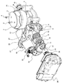
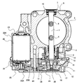
- the electronically controlled throttle device is a DC motor (hereinafter referred to as a DC motor) whose rotation is controlled by PWM control of a throttle valve (hereinafter referred to as a throttle valve 2) provided in an intake passage 1 for supplying air to an engine. It is driven by a motor 20) to control the amount of intake air.
- the motor 20 is mounted on the motor housing 20A integrally formed with the throttle body 5.
- the reduction gear mechanism (composed of 22, 23A, 23B, 13) that transmits the rotational force of the motor 20 to the rotation shaft of the throttle valve 2 (hereinafter referred to as the throttle shaft 3) is the throttle body 5.
- the cover 26 is provided with a resin connector portion in which positive and negative electric terminals (not shown) for supplying electric power to the motor 20 are formed.
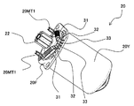
- the inductor holder 31H (FIG. 4) is integrally molded with the resin portion of the brush holder 20BH (FIG. 3) that holds the brush 20BR (FIG. 5) of the motor 20.
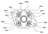
- the inductor holder 31H has a motor external connection terminal 20MT1 connected to a terminal arranged on the cover 26 and a pigtail 20PG (FIG. 5) arranged in the motor 20 for connection to the motor brush 20BR. It is provided between the connection terminal 20MT2 in the motor to be connected.
- the electronically controlled throttle device includes a throttle body 5 (body) having a throttle valve 2, a motor 20 with a brush for driving the throttle valve 2, a bracket 20F for attaching the motor 20 to the throttle body 5, and a motor.
- a filter circuit (inductor 31, inductor 31) that is electrically connected to the brush 20BR (brush) and electrically connected to the pigtail 20PG provided on the surface of the bracket 20F on the side of the motor 20 and electrically connected to the pigtail 20PG to reduce motor noise.
- a capacitor 32 and a resistor 33 are provided.
- the filter circuit is provided on the surface of the bracket opposite to the motor 20.
- a resistor 33 and a capacitor 32 are also connected to the in-motor connection terminal 20MT2 to which the inductor 31 is connected, and by being grounded via the motor bracket 20F, the effect of noise reduction is exhibited together with the inductor 31.
- connection position of the capacitor 32 is connected to the connection terminal 20MT2 in the motor in front of the inductor 31 rather than to the connection terminal 20MT1 outside the motor behind the inductor 31 with respect to the motor (pigtail 20PG).
- the noise reduction effect is high because the length of the wiring on which the noise is placed is shortened.
- the filter circuit includes a capacitor 32 electrically connected to the pigtail 20PG and a resistor 33 electrically connected to the pigtail 20PG.
- the capacitor 32 and the resistor 33 are provided on the surface of the bracket 20F on the side of the motor 20, but may be provided on the surface of the bracket 20F on the opposite side of the motor 20.
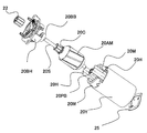
- a spring holder 20SH is arranged on the brush holder 20BH, and the motor spring 20BS held by the spring holder 20SH presses the motor brush 20BR in the direction of the motor shaft 20S (FIG. 3).
- the brush holder 20BH is provided with a pigtail retainer 20PH for holding the pigtail 20PG for connecting the motor brush 20BR and the motor internal connection terminal 20MT2, and holds the pigtail 20PG. Since the pigtail 20PG needs to move as the motor brush 20BR wears, it is held in a state where there is a margin in length.
- a ball bearing 20BB is held in the brush holder 20BH and supports one end of the motor shaft 20S.
- a commutator 20C and an armature 20AM are fixed to the motor shaft 20S.
- the brush holder 20BH is fixed to the tubular yoke 20Y, and a plain bearing 20PB is held on the side opposite to the side where the brush holder 20BH of the tubular yoke 20Y is held, and holds the other end of the motor shaft 20S. ..
- the magnet 20M is held by the magnet stay 20H in the cylindrical yoke 20Y.
- the aluminum die-cast throttle valve assembly (throttle body 5) includes an intake passage 1 (hereinafter referred to as a bore portion 1A) and a motor housing 20A for accommodating the motor 20. It is molded.
- a metal rotation shaft (hereinafter referred to as a throttle shaft 3) is arranged on the throttle body 5 along one diameter line of the bore portion 1A. Both ends of the throttle shaft 3 are rotationally supported by needle bearings as bearings 8 and 9. The bearings 8 and 9 are press-fitted and fixed to the bearing boss portions 6 and 7 provided in the throttle body 5.
- the bearing 9 is press-fitted into the throttle body 5 after being press-fitted into the throttle shaft 3. After that, the amount of movement in the axial direction of the throttle shaft 3 is regulated by being pressed by the cap 10 press-fitted into the throttle body 5.
- the throttle shaft 3 is rotatably supported with respect to the throttle body 5.
- a throttle valve (hereinafter referred to as a throttle valve 2) made of a metal disk is inserted into the slit provided in the throttle shaft 3 and fixed to the throttle shaft 3 with a screw 4.
- a throttle valve 2 rotates, and as a result, the cross-sectional area of the intake passage 1 changes and the intake air flow rate to the engine is controlled.
- the motor housing 20A is formed substantially in parallel with the throttle shaft 3, and the motor 20 composed of a brush-type DC motor is inserted into the motor housing 20A, and the throttle body 5 is inserted.
- the flange portion of the motor bracket 20F (FIG. 7) is fixed to the side wall of the motor bracket by screwing it with a screw 21.
- a wave washer 25 is arranged at the end of the motor 20 to hold the motor 20.
- the openings of the bearing boss portions 6 and 7 are sealed by the bearing 8 and the cap 10, forming a shaft seal portion and being configured to maintain airtightness. Further, the cap 10 on the bearing boss portion 7 side prevents the end portion of the throttle shaft 3 and the bearing 9 from being exposed. This prevents air from leaking from the bearings 8 and 9, or grease for lubricating the bearings 8 and 9 from leaking into the outside air or into the sensor chamber described later.
- a metal gear 22 having the smallest number of teeth is fixed to the end of the rotating shaft of the motor 20.
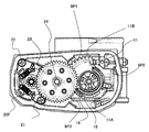
- a reduction gear mechanism and a spring mechanism for rotationally driving the throttle shaft 3 are collectively arranged on the side surface of the throttle body on the side where the gear 22 is provided. These mechanical parts are covered with a resin cover (hereinafter referred to as a gear cover) 26 fixed to the side surface of the throttle body 5.
- the throttle gear 11 is fixed to the end of the throttle shaft 3 on the gear cover 26 side.
- the throttle gear 11 is composed of a metal plate 12 and a resin gear portion 13 resin-molded on the metal plate 12.
- the resin gear portion 13 is molded on the metal plate 12 by resin molding.
- the metal plate 12 has a hole in the center.
- the tip of the throttle shaft 3 is inserted into the hole of the metal plate 12, and the nut 17 is screwed into the threaded portion to fix the metal plate 12 to the throttle shaft 3.
- the metal plate 12 and the resin gear portion 13 formed therein rotate integrally with the throttle shaft 3.
- a default spring 15 formed of a string-wound spring is sandwiched between the back surface of the throttle gear 11 and the default lever 16. Further, a return spring 14 formed of a string-wound spring is sandwiched between the back surface of the default lever 16 and the side surface of the throttle body 5.
- the initial position of the throttle valve 2 that is, the throttle valve 2 is the initial position when the power of the motor 20 is turned off, and the given opening position is the default open position. Degree. Therefore, when the throttle valve 2 is opened more than the default opening, the load in the closing direction toward the default opening is applied by the return spring 14, and when the throttle valve 2 is closed than the default opening, the default spring 15 is used. The load in the opening direction toward the default opening works.
- the gear shaft 24 made of a metal material press-fitted and fixed to the side surface of the throttle body 5 is rotatably supported.
- the intermediate gear 23 (FIG. 7) is engaged.
- the intermediate gear 23 includes a large-diameter gear 23A that meshes with the gear 22 and a small-diameter gear 23B that meshes with the throttle gear 11.
- Both gears 23A and 23B are integrally molded by resin molding.
- These gears 22, 23A, 23B, 11 constitute a two-stage reduction gear mechanism.
- the rotation of the motor 20 is transmitted to the throttle shaft 3 via the reduction gear mechanism.
- the inductor 31 is mounted at a position opposite to the gear 23A with respect to the motor shaft 20S.
- at least one of the pigtails 20PG inside the motor 20 is arranged on the side opposite to the gear 23A with respect to the motor shaft 20S, so that the inductor 31 and the pigtail 20PG are arranged at overlapping positions with the bracket 20F interposed therebetween.
- the filter circuit is arranged so as to overlap the pigtail 20PG in the axial direction of the motor 20 via the bracket 20F.
- the filter circuit includes an inductor 31 that is electrically connected to the pigtail 20PG, and the inductor 31 is arranged so as to overlap the pigtail 20PG in the axial direction of the motor 20 via the bracket 20F.
- the electronically controlled throttle device includes a gear 22 (first gear) attached to one end of the shaft of the motor 20, a throttle shaft 3 to which the throttle valve 2 is attached, and a throttle gear 11 (second gear) attached to one end of the throttle shaft 3. ), And a gear 23 (third gear) that transmits the rotation of the gear 22 (first gear) to the throttle gear 11 (second gear).
- the inductor 31 is located on the side opposite to the gear 23 (third gear) with the shaft of the motor 20 interposed therebetween. Since the inductor 31 is separated from the gear 23, the inductor 31 can be enlarged without interfering with the gear 23.
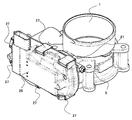
- a resin gear cover 26 A groove for inserting the seal member 30 is formed on the peripheral edge of the gear cover 26 on the opening end side, and when the gear cover 26 is put on the throttle body 5 with the seal member 30 mounted in this groove, the seal member 30 is formed. Is in close contact with the end surface of the frame around the gear storage chamber formed on the side surface of the throttle body 5 to shield the gear storage chamber from the outside air. As shown in FIG. 8, in this state, the gear cover 26 is fixed to the throttle body 5 with six clips 27.
- the rotation angle detection device that is, the throttle sensor, formed between the reduction gear mechanism configured as described above and the gear cover 26 covering the reduction gear mechanism will be specifically described below.
- the resin holder 19 is fixed to the end of the throttle shaft 3 on the gear cover side by press fitting via the inserter 29.
- a conductor 18 (FIG. 7) formed by press working is attached to the flat surface portion of the tip of the resin holder 19 by integral molding. Therefore, when the motor 20 rotates and the throttle valve 2 rotates, the conductor 18 also rotates integrally.
- the TPS substrate 28 (FIG. 6) is fixed to the gear cover 26 at a position facing the conductor 18.
- the ASIC arranged on the TPS substrate 28 detects the opening degree of the throttle valve 2 by detecting the angle of the conductor 18, and supplies the sensor output to the ECU.
- 5P1 to 5P3 arranged on the throttle body 5 are walls for positioning the gear cover 26, and the positioning projections of the gear cover 26 are engaged with the three walls so that the TPS board 28 and the conductor 18 on the rotating side are engaged. Can be positioned and output a signal within the required tolerance.
- the fully open stopper 11A mechanically determines the fully open position of the throttle gear 11, and is composed of protrusions integrally formed on the side wall of the throttle body.
- the present invention is not limited to the above-described embodiment, but includes various modifications.
- the above-mentioned examples have been described in detail in order to explain the present invention in an easy-to-understand manner, and are not necessarily limited to those having all the described configurations.
- it is possible to replace a part of the configuration of one embodiment with the configuration of another embodiment and it is also possible to add the configuration of another embodiment to the configuration of one embodiment.
- the embodiment of the present invention may have the following aspects.
- the bracket comprises a body having a throttle valve, a motor with a brush, a bracket in contact with the motor and connected to the body, and a circuit element for suppressing noise transmitted from the motor.
- the circuit element has a pigtail portion connected to the brush and provided on the side where the motor is arranged, and when viewed from the axial direction of the rotation axis of the motor, the circuit element has the motor with the pigtail portion as a boundary.
- An electronically controlled throttle device provided on the side opposite to the arranged side and arranged at a position overlapping the pigtail portion.
- the inductor was mounted on the opposite side of the motor coil, that is, on the outside of the motor, with respect to the bracket for fixing the motor to the valve device, not inside the motor.
- an inductor having a larger inductance can be provided, and an inductor sufficient to reduce radiation noise of the motor can be mounted. ..
Landscapes
- Engineering & Computer Science (AREA)
- Chemical & Material Sciences (AREA)
- Combustion & Propulsion (AREA)
- Mechanical Engineering (AREA)
- General Engineering & Computer Science (AREA)
- Power Engineering (AREA)
- Physics & Mathematics (AREA)
- Electromagnetism (AREA)
- Control Of Throttle Valves Provided In The Intake System Or In The Exhaust System (AREA)
- Dc Machiner (AREA)
- Connection Of Motors, Electrical Generators, Mechanical Devices, And The Like (AREA)
Abstract
Description
図1~図6に基づき本実施例の電制スロットル装置の構成を説明する。
Claims (6)
- スロットル弁を有するボディと、
前記スロットル弁を駆動するブラシ付きのモータと、
前記モータを前記ボディに取り付けるブラケットと、
前記ブラシと電気的に接続され、かつ前記モータの側の前記ブラケットの面に設けられるピグテールと、
前記ピグテールに電気的に接続され、前記モータのノイズを低減するフィルタ回路と、を備え、
前記フィルタ回路は、
前記モータとは反対側の前記ブラケットの面に設けられる
ことを特徴とする電制スロットル装置。 - 請求項1に記載の電制スロットル装置であって、
前記フィルタ回路は、
前記モータの軸方向に前記ブラケットを介して前記ピグテールと重なるように配置される
ことを特徴とする電制スロットル装置。 - 請求項2に記載の電制スロットル装置であって、
前記フィルタ回路は、
前記ピグテールに電気的に接続されるインダクタを含み、
前記インダクタは、
前記モータの軸方向に前記ブラケットを介して前記ピグテールと重なるように配置される
ことを特徴とする電制スロットル装置。 - 請求項3に記載の電制スロットル装置であって、
前記フィルタ回路は、
前記ピグテールに電気的に接続されるコンデンサ、及び前記ピグテールに電気的に接続される抵抗体を含み、
前記コンデンサと抵抗体は、
前記モータの側の前記ブラケットの面に設けられる
ことを特徴とする電制スロットル装置。 - 請求項3に記載の電制スロットル装置であって、
前記フィルタ回路は、
前記ピグテールに電気的に接続されるコンデンサ、及び前記ピグテールに電気的に接続される抵抗体を含み、
前記コンデンサと抵抗体は、
前記モータとは反対側の前記ブラケットの面に設けられる
ことを特徴とする電制スロットル装置。 - 請求項3に記載の電制スロットル装置であって、
前記モータの軸の一端に取り付けられる第1ギアと、
前記スロットル弁が取り付けられるスロットルシャフトと、
前記スロットルシャフトの一端に取り付けられる第2ギアと、
前記第1ギアの回転を前記第2ギアへ伝達する第3ギアと、を備え、
前記インダクタは、
前記モータの軸を挟んで前記第3ギアと反対側に位置する
ことを特徴とする電制スロットル装置。
Priority Applications (3)
| Application Number | Priority Date | Filing Date | Title |
|---|---|---|---|
| US18/002,315 US11946431B2 (en) | 2020-07-09 | 2021-07-06 | Electronically controlled throttle device |
| JP2022535355A JP7377360B2 (ja) | 2020-07-09 | 2021-07-06 | 電制スロットル装置 |
| CN202180042590.2A CN115803513B (zh) | 2020-07-09 | 2021-07-06 | 电控节气门装置 |
Applications Claiming Priority (2)
| Application Number | Priority Date | Filing Date | Title |
|---|---|---|---|
| JP2020118587 | 2020-07-09 | ||
| JP2020-118587 | 2020-07-09 |
Publications (1)
| Publication Number | Publication Date |
|---|---|
| WO2022009895A1 true WO2022009895A1 (ja) | 2022-01-13 |
Family
ID=79553182
Family Applications (1)
| Application Number | Title | Priority Date | Filing Date |
|---|---|---|---|
| PCT/JP2021/025497 Ceased WO2022009895A1 (ja) | 2020-07-09 | 2021-07-06 | 電制スロットル装置 |
Country Status (4)
| Country | Link |
|---|---|
| US (1) | US11946431B2 (ja) |
| JP (1) | JP7377360B2 (ja) |
| CN (1) | CN115803513B (ja) |
| WO (1) | WO2022009895A1 (ja) |
Citations (5)
| Publication number | Priority date | Publication date | Assignee | Title |
|---|---|---|---|---|
| JP2000184661A (ja) * | 1998-12-15 | 2000-06-30 | Jidosha Denki Kogyo Co Ltd | モータ |
| JP2002315274A (ja) * | 2001-02-06 | 2002-10-25 | Asmo Co Ltd | モータ |
| JP2003189542A (ja) * | 2001-12-18 | 2003-07-04 | Mitsuba Corp | 変速機付きモータアクチュエータ |
| JP2013155650A (ja) * | 2012-01-30 | 2013-08-15 | Hitachi Automotive Systems Ltd | モータ駆動式絞り弁制御装置 |
| JP2017208947A (ja) * | 2016-05-19 | 2017-11-24 | 日立オートモティブシステムズエンジニアリング株式会社 | 直流電動機 |
Family Cites Families (5)
| Publication number | Priority date | Publication date | Assignee | Title |
|---|---|---|---|---|
| JP4376017B2 (ja) * | 2003-08-01 | 2009-12-02 | 株式会社デンソー | 電子制御式スロットル制御装置 |
| JP2006097500A (ja) * | 2004-09-28 | 2006-04-13 | Honda Motor Co Ltd | 汎用エンジンのスロットル装置 |
| JP5877100B2 (ja) * | 2012-03-23 | 2016-03-02 | アスモ株式会社 | ブラシホルダ、ブラシ装置、モータ及びブラシ装置の製造方法 |
| DE102012103928A1 (de) * | 2012-05-04 | 2013-11-07 | Pierburg Gmbh | Gleichstrommotor zum Antrieb von Aggregaten eines Kraftfahrzeugs |
| JP6379782B2 (ja) * | 2013-07-26 | 2018-08-29 | 株式会社デンソー | モータ |
-
2021
- 2021-07-06 JP JP2022535355A patent/JP7377360B2/ja active Active
- 2021-07-06 CN CN202180042590.2A patent/CN115803513B/zh active Active
- 2021-07-06 WO PCT/JP2021/025497 patent/WO2022009895A1/ja not_active Ceased
- 2021-07-06 US US18/002,315 patent/US11946431B2/en active Active
Patent Citations (5)
| Publication number | Priority date | Publication date | Assignee | Title |
|---|---|---|---|---|
| JP2000184661A (ja) * | 1998-12-15 | 2000-06-30 | Jidosha Denki Kogyo Co Ltd | モータ |
| JP2002315274A (ja) * | 2001-02-06 | 2002-10-25 | Asmo Co Ltd | モータ |
| JP2003189542A (ja) * | 2001-12-18 | 2003-07-04 | Mitsuba Corp | 変速機付きモータアクチュエータ |
| JP2013155650A (ja) * | 2012-01-30 | 2013-08-15 | Hitachi Automotive Systems Ltd | モータ駆動式絞り弁制御装置 |
| JP2017208947A (ja) * | 2016-05-19 | 2017-11-24 | 日立オートモティブシステムズエンジニアリング株式会社 | 直流電動機 |
Also Published As
| Publication number | Publication date |
|---|---|
| US20230243312A1 (en) | 2023-08-03 |
| CN115803513B (zh) | 2024-12-27 |
| CN115803513A (zh) | 2023-03-14 |
| JPWO2022009895A1 (ja) | 2022-01-13 |
| JP7377360B2 (ja) | 2023-11-09 |
| US11946431B2 (en) | 2024-04-02 |
Similar Documents
| Publication | Publication Date | Title |
|---|---|---|
| EP1191210B1 (en) | Throttle device of internal combustion engine | |
| US6591809B2 (en) | Throttle device for internal-combustion engine | |
| US9546606B2 (en) | Electronic throttle body assembly | |
| JP3848275B2 (ja) | 内燃機関の絞り弁制御装置 | |
| JP3945680B2 (ja) | 内燃機関のスロットル装置 | |
| US20120304964A1 (en) | Motor-Driven Throttle Valve Control Device Having Inductance-Based Noncontact Rotation Angle Detecting Device, and Rotation Angle Detecting Device Used for the Same | |
| CN103375277B (zh) | 具有电子定位线圈的节流回复弹簧 | |
| US20050109315A1 (en) | Electronically controlled throttle device | |
| CN105121827B (zh) | 用于驱动内燃机阀单元的致动器 | |
| KR20050062410A (ko) | 하우징 내에 수용된 액츄에이터를 위한 지지 장치 | |
| JP4376017B2 (ja) | 電子制御式スロットル制御装置 | |
| US20040103882A1 (en) | Throttle control heat dissipation device | |
| JP7377360B2 (ja) | 電制スロットル装置 | |
| CN102667108A (zh) | 具有连接器的电路模块 | |
| JP5450511B2 (ja) | インダクタンス式回転角度検出装置及びそれを備えたモータ駆動式の絞り弁制御装置 | |
| EP1164279A1 (en) | Exhaust gas recirculating valve device | |
| JP3948016B2 (ja) | スロットル装置 | |
| CN1383601A (zh) | 带可调电位器的变速驱动装置 | |
| JP2014136964A (ja) | 電子制御スロットル装置 | |
| JP2013155650A (ja) | モータ駆動式絞り弁制御装置 | |
| WO2019138672A1 (ja) | 車載用dcモータのノイズ低減構造及びモータ駆動式弁装置 | |
| EP1571313A1 (en) | Integrated supply unit for internal combustion engines | |
| JP2020200765A (ja) | 電動スロットル装置のカバー構造及びそれを備える電動スロットル装置 | |
| KR20040032773A (ko) | 스로틀 제어 장치 및 모터 장착 방법 | |
| JP2021095895A (ja) | スロットル装置 |
Legal Events
| Date | Code | Title | Description |
|---|---|---|---|
| 121 | Ep: the epo has been informed by wipo that ep was designated in this application |
Ref document number: 21837410 Country of ref document: EP Kind code of ref document: A1 |
|
| ENP | Entry into the national phase |
Ref document number: 2022535355 Country of ref document: JP Kind code of ref document: A |
|
| NENP | Non-entry into the national phase |
Ref country code: DE |
|
| 122 | Ep: pct application non-entry in european phase |
Ref document number: 21837410 Country of ref document: EP Kind code of ref document: A1 |
|
| WWG | Wipo information: grant in national office |
Ref document number: 202180042590.2 Country of ref document: CN |