WO2022009804A1 - 電子機器保持装置 - Google Patents
電子機器保持装置 Download PDFInfo
- Publication number
- WO2022009804A1 WO2022009804A1 PCT/JP2021/025181 JP2021025181W WO2022009804A1 WO 2022009804 A1 WO2022009804 A1 WO 2022009804A1 JP 2021025181 W JP2021025181 W JP 2021025181W WO 2022009804 A1 WO2022009804 A1 WO 2022009804A1
- Authority
- WO
- WIPO (PCT)
- Prior art keywords
- electronic device
- accommodating portion
- accommodating
- cup
- vehicle
- Prior art date
- Legal status (The legal status is an assumption and is not a legal conclusion. Google has not performed a legal analysis and makes no representation as to the accuracy of the status listed.)
- Ceased
Links
Images







Classifications
-
- B—PERFORMING OPERATIONS; TRANSPORTING
- B60—VEHICLES IN GENERAL
- B60R—VEHICLES, VEHICLE FITTINGS, OR VEHICLE PARTS, NOT OTHERWISE PROVIDED FOR
- B60R11/00—Arrangements for holding or mounting articles, not otherwise provided for
- B60R11/02—Arrangements for holding or mounting articles, not otherwise provided for for radio sets, television sets, telephones, or the like; Arrangement of controls thereof
-
- B—PERFORMING OPERATIONS; TRANSPORTING
- B60—VEHICLES IN GENERAL
- B60N—SEATS SPECIALLY ADAPTED FOR VEHICLES; VEHICLE PASSENGER ACCOMMODATION NOT OTHERWISE PROVIDED FOR
- B60N3/00—Arrangements or adaptations of other passenger fittings, not otherwise provided for
- B60N3/10—Arrangements or adaptations of other passenger fittings, not otherwise provided for of receptacles for food or beverages, e.g. refrigerated
- B60N3/101—Arrangements or adaptations of other passenger fittings, not otherwise provided for of receptacles for food or beverages, e.g. refrigerated fixed
-
- B—PERFORMING OPERATIONS; TRANSPORTING
- B60—VEHICLES IN GENERAL
- B60R—VEHICLES, VEHICLE FITTINGS, OR VEHICLE PARTS, NOT OTHERWISE PROVIDED FOR
- B60R11/00—Arrangements for holding or mounting articles, not otherwise provided for
- B60R2011/0001—Arrangements for holding or mounting articles, not otherwise provided for characterised by position
- B60R2011/0003—Arrangements for holding or mounting articles, not otherwise provided for characterised by position inside the vehicle
- B60R2011/0007—Mid-console
-
- B—PERFORMING OPERATIONS; TRANSPORTING
- B60—VEHICLES IN GENERAL
- B60R—VEHICLES, VEHICLE FITTINGS, OR VEHICLE PARTS, NOT OTHERWISE PROVIDED FOR
- B60R11/00—Arrangements for holding or mounting articles, not otherwise provided for
- B60R2011/0042—Arrangements for holding or mounting articles, not otherwise provided for characterised by mounting means
- B60R2011/0049—Arrangements for holding or mounting articles, not otherwise provided for characterised by mounting means for non integrated articles
- B60R2011/0064—Connection with the article
- B60R2011/0075—Connection with the article using a containment or docking space
-
- B—PERFORMING OPERATIONS; TRANSPORTING
- B60—VEHICLES IN GENERAL
- B60R—VEHICLES, VEHICLE FITTINGS, OR VEHICLE PARTS, NOT OTHERWISE PROVIDED FOR
- B60R11/00—Arrangements for holding or mounting articles, not otherwise provided for
- B60R11/02—Arrangements for holding or mounting articles, not otherwise provided for for radio sets, television sets, telephones, or the like; Arrangement of controls thereof
- B60R2011/0294—Apparatus with multi-functionalities, e.g. radio and telephone
Definitions
- the present invention relates to an electronic device holding device.
- Patent Document 1 An electronic device holding device for holding an electronic device such as a smartphone via an attachment arranged in a cup holder provided in a center cluster of a vehicle has been proposed (see, for example, Patent Document 1).
- This electronic device holding device is installed as a pull-out cup holder in the center cluster of the vehicle.
- An attachment can be inserted into this cup holder.
- the attachment is composed of an insert body formed in a columnar shape and a case body formed on the upper portion of the insert body.
- the case body is formed so that a smartphone can be stored.
- the surface of the case is notched so that the stored smartphone can be operated.
- the smartphone can be stored in the attachment that can be inserted into the cup holder, and the smartphone can be placed in the cup holder.
- the electronic device holding device described in Patent Document 1 also serves as a cup holder for holding an electronic device such as a smartphone. For this reason, the device may not have a containment structure in which the relationship between the cup holder and the containment of the electronic device is optimized.
- An object of the present invention is to provide an electronic device holding device having a housing structure in which the relationship between the cup holder and the storage portion of the electronic device is optimized.
- the electronic device holding device includes a first housing unit for holding an electronic device provided with a display unit, and a communication unit which is partially cut out and communicates with the first storage unit. It has a second accommodating portion that has a wall portion and is adjacent to the first accommodating portion, and the display unit can be visually recognized from the side of the second accommodating portion through the communication portion, and the first accommodating portion. And the second accommodating portion are integrally configured and arranged.
- the electronic device holding device may be arranged on the center console of the vehicle, and the display unit may be visually recognized from the driver's seat side of the vehicle more easily than from the passenger seat side.
- the first accommodating unit may be an electronic device holding device having a power feeding device for supplying power to the electronic device.
- the power feeding device may be an electronic device holding device, which is a non-contact power feeding device.
- the first accommodating portion may be an electronic device holding device having an inclined wall portion on which the electronic device is tilted and leaned against.
- the first accommodating portion may be an electronic device holding device having a holding mechanism (center lining mechanism) for holding the electronic device at a predetermined position.
- An electronic device holding device may have a groove (tunnel structure) that can be wired at the bottom of the first accommodating portion and the second accommodating portion.
- An electronic device holding device capable of accommodating a cup in the second accommodating portion, and the first accommodating portion and the second accommodating portion are mounted in the passenger compartment of the vehicle as an integrally configured cup holder. There may be.
- the second accommodating portion may be two, and the electronic device holding device may be provided with the communication portion between the two second accommodating portions.
- the cup holder may be an electronic device holding device arranged on the armrest of the seat of the vehicle.
- the cup holder may be an electronic device holding device in which a plurality of cup holders are arranged side by side. 12)
- the cup holder may be arranged on the upper surface of the instrument panel of the vehicle.
- an electronic device holding device having a housing structure in which the relationship between the cup holder and the storage portion of the electronic device is optimized.
- FIG. 1 is a perspective view showing an overall configuration of an electronic device holding device according to a first embodiment of the present invention.
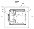
- FIG. 2A is a plan view of the electronic device holding device according to the first embodiment.
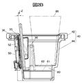
- FIG. 2B is a cross-sectional view taken along the line AA of FIG. 2A.
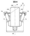
- FIG. 3A is a plan view of an electronic device holding device obtained by rotating FIG. 2A by 90 °.
- FIG. 3B is a cross-sectional view taken along the line BB of FIG. 3A.
- FIG. 4 shows an example in which the electronic device holding device is mounted on the vehicle, and is a perspective view of the inside of the vehicle showing the case where the electronic device holding device is mounted on the center console.
- FIG. 5A is a plan view of the electronic device holding device according to the second embodiment.
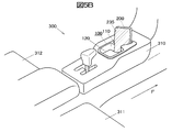
- FIG. 5B shows an example in which the electronic device holding device is mounted on the vehicle, and is a perspective view of the inside of the vehicle showing the case where the electronic device holding device is mounted on the center console.
- FIG. 6 is a perspective view of the electronic device holding device according to the third embodiment.
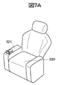
- FIG. 7A is a perspective view showing the entire seat of the vehicle to which the electronic device holding device according to the fourth embodiment is applied.
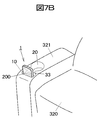
- FIG. 7B is a perspective view showing a state in which the electronic device holding device is arranged on the armrest of the seat of the vehicle.
- FIG. 8 is a perspective view showing a state in which the electronic device holding device according to the fifth embodiment is arranged on the armrest at the center of the rear seat of the vehicle.
- FIG. 9 is a perspective view showing a state in which the electronic device holding device according to the sixth embodiment is arranged on the instrument panel of the vehicle.
- FIG. 1 is a perspective view showing the overall configuration of the electronic device holding device 1 according to the first embodiment of the present invention.
- the electronic device holding device 1 includes an electronic device accommodating unit 10 as a first accommodating unit for holding an electronic device 200 provided with a display unit 235, and a part thereof.
- a cup accommodating portion 20 as a second accommodating portion having a wall portion 30 having a communication portion 33 communicating with the first accommodating portion 10 and capable of accommodating a cup adjacent to the electronic device accommodating portion 10.
- the display unit 235 can be visually recognized from the side of the cup accommodating unit 20 through the communication unit 33, and the electronic device accommodating unit 10 and the cup accommodating unit 20 are configured to be integrally configured and arranged. ..
- the electronic device holding device 1 can be arranged in the vehicle interior of the vehicle 300.
- the electronic device 200 is a smartphone, a mobile phone, a mobile terminal, or the like, but in the present embodiment, the electronic device 200 is an electronic device assuming a smartphone.
- the electronic device accommodating unit 10 accommodates an electronic device 200 such as a smartphone, but in the present embodiment, the electronic device 200 is accommodated in a leaning state.
- the cup accommodating portion 20 is configured to accommodate a cup, a bottle, etc. containing a drink or the like, but is used for accommodating other things such as a pen, glasses, etc. other than the cup and the bottle. It is also possible.
- FIG. 2A is a plan view of the electronic device holding device according to the first embodiment
- FIG. 2B is a cross-sectional view taken along the line AA of FIG. 2A
- FIG. 3A is a plan view of the electronic device holding device obtained by rotating FIG. 2A by 90 °
- FIG. 3B is a cross-sectional view taken along the line BB of FIG. 3A.
- the electronic device holding device 1 has a cup accommodating portion 20 that accommodates an electronic device accommodating portion 10 as a first accommodating portion, a cup 80 as a second accommodating portion, and the like in a housing 40. It is configured to have and.
- the housing 40 is composed of a flange portion 42 that serves as a mounting flange for the center console 310 of the vehicle 300, and a main body portion 44 that has an electronic device accommodating portion 10 and a cup accommodating portion 20 as internal spaces.
- the flange portion 42 can be formed of, for example, a designed design member, and the main body portion 44 can be formed of, for example, a hard resin or the like.
- a wall portion 30 is formed between the electronic device accommodating portion 10 as the first accommodating portion and the cup accommodating portion 20 as the adjacent second accommodating portion. .. As shown in FIG. 2A, the wall portion 30 partitions between the electronic device accommodating portion 10 and the cup accommodating portion 20.
- the vicinity of the central portion of the wall portion 30 is cut out to form a communication portion 33 in which the electronic device accommodating portion 10 and the cup accommodating portion 20 communicate with each other.
- the display unit 235 of the electronic device 200 housed in the electronic device accommodating unit 10 can be visually recognized from the side of the cup accommodating unit 20 through the communication unit 33.
- the display unit 235 of the electronic device 200 can be clearly seen through the communication unit 33.
- the communication portion 33 is provided on the wall portion 30.
- the electronic device accommodating unit 10 as the first accommodating unit has a power feeding device for supplying power to the electronic device 200. It should be noted that the power supply includes charging.
- the power supply device is a non-contact power supply device.
- the power feeding device 50 is attached to the outer wall portion 36 of the back wall portion 35 on which the electronic device accommodating portion 10 is leaned.
- the power feeding coil 52 is arranged to face the power receiving coil (not shown) mounted inside the electronic device 200 housed inside the electronic device accommodating portion 10. ing.
- the power feeding coil 52 feeds power in a state of being electromagnetically coupled to a power receiving coil (not shown) mounted inside the electronic device 200 housed in the electronic device accommodating unit 10. It can be charged.
- the power feeding device 50 can feed and charge the electronic device 200 in a non-contact manner via the power receiving coil of the electronic device 200 by electromagnetic induction.
- the power feeding device 50 can be powered and charged by, for example, when the vehicle 300 is in the operation mode or the ACC mode, so that the power can be supplied only by inserting the electronic device 200 into the electronic device holding device 1 and mounting the electronic device 200. It can also be charged.
- the electronic device accommodating portion 10 as the first accommodating portion has a back wall portion 35 as an inclined wall portion on which the electronic device 200 is tilted and leaned against.
- the back wall portion 35 shown in FIG. 2B is formed as an inclined wall portion having an inclination angle ⁇ with respect to the vertical direction Z.
- this inclination angle ⁇ is an angle exceeding zero in FIG. 2B, and can be set in consideration of the inclination angle of the cup having a conical shape.
- the space between the electronic device accommodating portion 10 and the cup accommodating portion 20 can be optimized and minimized.
- the electronic device 200 can be stably held. Further, when the electronic device holding device 1 is mounted on a vehicle, the electronic device 200 can be stably held against acceleration when the vehicle starts, deceleration when the vehicle is stopped, vibration during traveling, and the like.
- the bottom 60 of the electronic device accommodating portion 10 as the first accommodating portion and the cup accommodating portion 20 as the second accommodating portion has a groove portion 61 that can be wired.
- the groove 61 forms a tunnel structure under the bottom plate 62, as shown in FIG. 2B.
- a USB cable or the like for feeding and charging the electronic device 200 by wire is arranged in this groove 61.
- a connector such as a USB cable can be attached to the electronic device 200, and power can be supplied and charged by wire.
- the electronic device accommodating unit 10 has a holding mechanism 70 (center alignment mechanism) that holds the electronic device 200 in a predetermined position. As shown in FIGS. 3A and 3B, the holding mechanism 70 is supported by two members, the right side holding member 71 and the left side holding member 75, so as to sandwich the electronic device 200 from the left and right.
- a holding mechanism 70 center alignment mechanism
- the right side holding member 71 and the left side holding member 75 have an arm shape rotatably supported by rotation fulcrums 72 and 76, respectively.
- the contact portion 73 abuts on the side surface 201 of the electronic device 200 with the rotation fulcrum 72 as the center.
- the right side holding member 71 is provided with a spring or the like that generates an urging force in which the contact portion 73 is urged to the side surface 201 of the electronic device 200.
- the contact portion 77 abuts on the side surface 202 of the electronic device 200 with the rotation fulcrum 76 as the center.
- the holding structure can be any means of mechanism such as rotation support, slide, etc. as long as the electronic device can be aligned in the center.
- the electronic device 200 is center-aligned with the central axis CL. Since the positional relationship between the electronic device 200 and the feeding coil 52 is stably determined, the charging efficiency is good and stable feeding and charging are possible in the above-mentioned non-contact type feeding and charging.
- the right side holding member 71 and the left side holding member 75 are provided with inclined contact portions 74 and 78, respectively.
- the inclined contact portion 74 of the right side holding member 71 abuts on the side surface 201 of the electronic device 200 and presses the electronic device 200 against the back wall portion 35.
- the inclined contact portion 78 of the left side holding member 75 abuts on the side surface 202 of the electronic device 200 and presses the electronic device 200 against the back wall portion 35.
- the electronic device 200 is pressed against the back wall portion 35, and the positional relationship between the electronic device 200 and the feeding coil 52 is stably determined. Therefore, in the above-mentioned non-contact type feeding and charging, the charging efficiency is good. Stable power supply and charging are possible. Further, when the electronic device holding device 1 is attached to the vehicle 300, the electronic device 200 can be stably held against acceleration when the vehicle starts, deceleration when the vehicle is stopped, vibration during traveling, and the like.
- FIG. 4 shows an example in which the electronic device holding device is mounted on the vehicle 300, and is a perspective view of the inside of the vehicle showing the case where the electronic device holding device is mounted on the center console 310.
- the electronic device holding device 1 can hold the electronic device 200, and also functions as a cup holder for holding the cup. That is, the cup can be accommodated in the cup accommodating portion 20 as the second accommodating portion, and the electronic device accommodating portion 10 and the cup accommodating portion 20 as the first accommodating portion are the passenger compartment of the vehicle 300 as an integrally configured cup holder. It is attached to.
- the electronic device 200 can be accommodated in the electronic device accommodating portion 10 so as to lean the electronic device 200 in the front direction (F direction) of the vehicle 300.
- the electronic device 200 can be stably held, and the electronic device 200 can be stably held against acceleration when the vehicle 300 starts, deceleration when the vehicle is stopped, vibration during traveling, and the like.
- the electronic device holding device 1 when the electronic device holding device 1 is mounted on the center console 310, the electronic device 200 can be placed in the electronic device accommodating portion 10 from either the driver's seat 311 side or the passenger seat 312 side.
- the display unit 235 of the electronic device 200 can be clearly seen through the communication unit 33.
- a wall portion 30 is formed between the electronic device accommodating portion 10 as the first accommodating portion and the cup accommodating portion 20 as the adjacent second accommodating portion, and the wall is formed. The vicinity of the central portion of the portion 30 is cut out to form a communication portion 33 in which the electronic device accommodating portion 10 and the cup accommodating portion 20 communicate with each other. As a result, the display unit 235 of the electronic device 200 housed in the electronic device accommodating unit 10 can be visually recognized from the side of the cup accommodating unit 20 through the communication unit 33.
- the electronic device accommodating portion 10 as the first accommodating portion has an inclined wall portion on which the electronic device 200 is inclined and leaned against. Thereby, the space between the electronic device accommodating portion 10 and the cup accommodating portion 20 can be minimized.
- the bottom 60 of the electronic device accommodating portion 10 as the first accommodating portion and the cup accommodating portion 20 as the second accommodating portion has a groove portion 61 that can be wired.
- a USB cable or the like can be arranged in the groove portion 61, and a connector such as a USB cable can be attached to the electronic device 200 to enable wired power supply and charging.
- the electronic device accommodating unit 10 has a holding mechanism 70 (center alignment mechanism) for holding the electronic device 200 at a predetermined position.
- the electronic device 200 is center-aligned with the central axis CL. Further, the electronic device 200 is pressed against the back wall portion 35. This enables stable power supply and charging with good charging efficiency in non-contact power supply and charging. Further, when the electronic device holding device 1 is attached to the vehicle 300, the electronic device 200 can be stably held against acceleration when the vehicle 300 starts, deceleration when the vehicle is stopped, vibration during traveling, and the like.
- FIG. 5A is a plan view of the electronic device holding device according to the second embodiment
- FIG. 5B shows an example in which the electronic device holding device is mounted on a vehicle and is mounted on a center console. It is a perspective view of the inside of a vehicle which showed.
- the electronic device holding device 100 has a predetermined angle ⁇ so that the display unit 235 of the electronic device 200 faces the driver's seat side when mounted on the vehicle 300, and is the first.
- An electronic device accommodating unit 10 as an accommodating unit is arranged.
- the electronic device accommodating unit 110 in the second embodiment has the same configuration as the electronic device accommodating unit 10 in the first embodiment, but as shown in FIG. 5A, the cup of the first embodiment. It is arranged so as to be inclined by a predetermined angle ⁇ with respect to the cup accommodating portion 120 similar to the accommodating portion 20.
- the predetermined angle ⁇ can be set to an arbitrary value exceeding zero (0 °) and 90 ° or less, but as an example in which the display unit 235 of the electronic device 200 is easily visible from the driver's seat 311 side, one example is given. , 30 °.
- the second embodiment has the following effects in addition to the effects of the first embodiment. (1) When visually recognizing the display unit 235 of the electronic device 200, it is easier to visually recognize the vehicle 300 from the driver's seat 311 side than from the passenger seat 312 side. (2) It becomes difficult to visually recognize the display unit 235 of the electronic device 200 from the passenger seat 312 side. Therefore, when the driver places the electronic device 200 on the electronic device accommodating unit 110, it is possible to protect the privacy from the passenger seat 312 side. (3) As shown in FIGS. 5A and 5B, since the electronic device accommodating portion 110 is arranged at an angle with respect to the front direction (F direction) of the vehicle 300, it is laterally arranged as compared with the first embodiment. The width dimension W can be small, and the space can be reduced in the lateral direction.
- the cup in the electronic device holding device 1 shown in the first embodiment, the cup can be accommodated in the cup accommodating portion 20 as the second accommodating portion, and the electronic device accommodating portion 10 and the cup accommodating portion 20 as the first accommodating unit It is mounted in the passenger compartment of the vehicle 300 as an integrally configured cup holder.
- the third embodiment there are two cup accommodating portions 20, and a communication portion 33 is provided between the two cup accommodating portions 20.
- FIG. 6 is a perspective view of the electronic device holding device according to the third embodiment.
- cups can be placed from the driver's seat 311 side and the passenger seat 312 side, respectively, and the display unit 235 of the electronic device 200 can be easily visually recognized through the communication unit 33.
- the display unit 235 of the electronic device 200 can be clearly seen through the communication unit 33.
- the cup in the electronic device holding device 1 shown in the first embodiment, the cup can be accommodated in the cup accommodating portion 20 as the second accommodating portion, and the electronic device accommodating portion 10 and the cup accommodating portion 20 as the first accommodating unit It is mounted in the passenger compartment of the vehicle 300 as an integrally configured cup holder.
- the cup holder is configured to be arranged on the armrest 321 of the seat 320 of the vehicle 300.
- FIG. 7A is a perspective view showing the entire seat of the vehicle to which the electronic device holding device according to the fourth embodiment is applied
- FIG. 7B is a state in which the electronic device holding device is arranged on the armrest of the vehicle seat. It is a perspective view which shows.
- a dedicated electronic device holding device 1 can be arranged in each seat 320, which can be used as a cup holder. Further, the electronic device 200 can be placed in the electronic device accommodating section 10, which has an effect that the display section 235 of the electronic device 200 can be easily visually recognized through the communication section 33. In particular, when the cup is not placed in the cup accommodating portion 20, the display portion of the electronic device 200 can be clearly seen through the communication portion 33.
- the cup in the electronic device holding device 1 shown in the first embodiment, the cup can be accommodated in the cup accommodating portion 20 as the second accommodating portion, and the electronic device accommodating portion 10 and the cup accommodating portion 20 as the first accommodating unit It is mounted in the passenger compartment of the vehicle 300 as an integrally configured cup holder.
- a plurality of cup holders are arranged side by side.
- FIG. 8 is a perspective view showing a state in which the electronic device holding device according to the fifth embodiment is arranged on the armrest at the center of the rear seat of the vehicle.
- the cup holder is configured to be arranged on the armrest 331 in the central portion of the rear seat 330 of the vehicle 300.
- Each person seated in the backseat 330 can be used as a cup holder.
- each electronic device 200 can be placed in the electronic device accommodating section 10, which has an effect that the display section of the electronic device 200 can be easily visually recognized through the communication section.
- the cup 80 is not placed in the cup accommodating portion 20, there is an effect that the display portion of the electronic device 200 can be clearly seen through the communication portion.
- the cup in the electronic device holding device 1 shown in the first embodiment, the cup can be accommodated in the cup accommodating portion 20 as the second accommodating portion, and the electronic device accommodating portion 10 and the cup accommodating portion 20 as the first accommodating unit It is mounted in the passenger compartment of the vehicle 300 as an integrally configured cup holder.
- the cup holder is configured to be arranged on the instrument panel.
- FIG. 9 is a perspective view showing a state in which the electronic device holding device according to the sixth embodiment is arranged on the instrument panel of the vehicle.
- the cup holder is arranged on the upper surface portion 355 of the instrument panel 350 in front of the vehicle of the front seat 312 of the vehicle 300.
- Each person seated in the front seat 312 can use it as a cup holder.
- each electronic device 200 can be placed in the electronic device accommodating section 10, which has an effect that the display section of the electronic device 200 can be easily visually recognized through the communication section.
- the cup 80 is not placed in the cup accommodating portion 20, there is an effect that the display portion of the electronic device 200 can be clearly seen through the communication portion.
Landscapes
- Engineering & Computer Science (AREA)
- Mechanical Engineering (AREA)
- Physics & Mathematics (AREA)
- Thermal Sciences (AREA)
- Transportation (AREA)
- Vehicle Step Arrangements And Article Storage (AREA)
- Passenger Equipment (AREA)
- Fittings On The Vehicle Exterior For Carrying Loads, And Devices For Holding Or Mounting Articles (AREA)
Abstract
電子機器保持装置(1)は、表示部(235)を備えた電子機器(200)を保持する電子機器収容部(第1収容部(10))と、一部が切り欠かれて第1収容部(10)と連通する連通部(33)を備えた壁部(30)を有して第1収容部(10)に隣接するカップ収容部(第2収容部(20))と、を有し、表示部(235)は、第2収容部(20)の側から連通部(33)を通して視認でき、第1収容部(10)と第2収容部(20)は一体的に構成されて配置される。
Description
本発明は、電子機器保持装置に関する。
車両のセンタークラスターに設けられたカップホルダに配置されたアタッチメントを介してスマートフォン等の電子機器を保持する電子機器保持装置が提案されている(例えば、特許文献1参照)。
この電子機器保持装置は、車両のセンタークラスターに、引き出し式のカップホルダとして設けられている。このカップホルダには、アタッチメントが差し込み可能となっている。アタッチメントは、円柱状に形成された差込体と、この差込体の上部に形成されたケース体とから構成されている。ケース体は、スマートフォンを収納できるように形成されている。また、ケース体、収納したスマートフォンを操作可能となるように、その表面が大きく切り欠かれている。これにより、カップホルダに差し込み可能なアタッチメントにスマートフォンを収納でき、カップホルダにスマートフォンを配置できるとされている。
特許文献1に記載の電子機器保持装置は、カップホルダをスマートフォン等の電子機器の保持に兼用するものである。このため、この装置は、カップホルダと電子機器の収容部の関係が最適化された収容構造を有さない可能性がある。
本発明の目的は、カップホルダと電子機器の収容部の関係が最適化された収容構造を有する電子機器保持装置を提供することにある。
1)本発明の一実施例による電子機器保持装置は、表示部を備えた電子機器を保持する第1収容部と、一部が切り欠かれて前記第1収容部と連通する連通部を備えた壁部を有して前記第1収容部に隣接する第2収容部と、を有し、前記表示部は、前記第2収容部の側から前記連通部を通して視認でき、前記第1収容部と前記第2収容部は一体的に構成されて配置される。
2)車両のセンターコンソールに配置され、前記表示部の視認は、前記車両の運転席側からの方が助手席側からよりも視認しやすい、電子機器保持装置であってもよい。
3)前記第1収容部は、前記電子機器に給電する給電装置を有する、電子機器保持装置であってもよい。
4)前記給電装置は、非接触式の給電装置である、電子機器保持装置であってもよい。
5)前記第1収容部は、前記電子機器を傾斜して立てかける傾斜壁部を有する、電子機器保持装置であってもよい。
6)前記第1収容部には、前記電子機器を所定の位置に保持する保持機構(センターアライニング機構)を有する、電子機器保持装置であってもよい。
7)前記第1収容部及び前記第2収容部の底部には、配線可能な溝部(トンネル構造)を有する、電子機器保持装置であってもよい。
8)前記第2収容部にはカップが収容でき、前記第1収容部と前記第2収容部は一体的に構成されたカップホルダとして前記車両の車室内に装着される、電子機器保持装置であってもよい。
9)前記第2収容部は2つあり、前記2つの第2収容部の間に前記連通部を備える、電子機器保持装置であってもよい。
10)前記カップホルダは、前記車両の座席のアームレストに配置される、電子機器保持装置であってもよい。
11)前記カップホルダは、複数並べて配置される、電子機器保持装置であってもよい。
12)前記カップホルダは、前記車両のインストルメントパネルの上面部に配置されるものであってもよい。
2)車両のセンターコンソールに配置され、前記表示部の視認は、前記車両の運転席側からの方が助手席側からよりも視認しやすい、電子機器保持装置であってもよい。
3)前記第1収容部は、前記電子機器に給電する給電装置を有する、電子機器保持装置であってもよい。
4)前記給電装置は、非接触式の給電装置である、電子機器保持装置であってもよい。
5)前記第1収容部は、前記電子機器を傾斜して立てかける傾斜壁部を有する、電子機器保持装置であってもよい。
6)前記第1収容部には、前記電子機器を所定の位置に保持する保持機構(センターアライニング機構)を有する、電子機器保持装置であってもよい。
7)前記第1収容部及び前記第2収容部の底部には、配線可能な溝部(トンネル構造)を有する、電子機器保持装置であってもよい。
8)前記第2収容部にはカップが収容でき、前記第1収容部と前記第2収容部は一体的に構成されたカップホルダとして前記車両の車室内に装着される、電子機器保持装置であってもよい。
9)前記第2収容部は2つあり、前記2つの第2収容部の間に前記連通部を備える、電子機器保持装置であってもよい。
10)前記カップホルダは、前記車両の座席のアームレストに配置される、電子機器保持装置であってもよい。
11)前記カップホルダは、複数並べて配置される、電子機器保持装置であってもよい。
12)前記カップホルダは、前記車両のインストルメントパネルの上面部に配置されるものであってもよい。
本発明の一実施例によれば、カップホルダと電子機器の収容部の関係が最適化された収容構造を有する電子機器保持装置を提供することができる。
図1は、本発明の第1の実施の形態に係る電子機器保持装置1の全体構成を示す斜視図である。図1に示されるように、本発明の実施の形態に係る電子機器保持装置1は、表示部235を備えた電子機器200を保持する第1収容部としての電子機器収容部10と、一部が切り欠かれて第1収容部10と連通する連通部33を備えた壁部30を有して電子機器収容部10に隣接するカップを収容できる第2収容部としてのカップ収容部20と、を有し、表示部235は、カップ収容部20の側から連通部33を通して視認でき、電子機器収容部10とカップ収容部20は一体的に構成されて配置される、ように構成されている。
本実施の形態に係る電子機器保持装置1は、車両300の車室内に配置されることができる。また、電子機器200は、スマートフォン、携帯電話、携帯端末等であるが、本実施の形態では、スマートフォンを想定した電子機器とする。
電子機器収容部10は、スマートフォン等の電子機器200を収容するが、本実施の形態は、電子機器200を立て掛けた状態で収容する。
また、カップ収容部20は、飲み物等が入るカップ、ボトル等を収容できる形状に構成されたものであるが、カップ、ボトル以外でも、ペン、メガネ等の他のものを収容するために使用することも可能である。
〔第1の実施の形態〕
図2Aは、第1の実施の形態に係る電子機器保持装置の平面図であり、図2Bは、図2AのA-A線に沿う断面図である。また、図3Aは、図2Aを90°回転させた電子機器保持装置の平面図であり、図3Bは、図3AのB-B線に沿う断面図である。
図2Aは、第1の実施の形態に係る電子機器保持装置の平面図であり、図2Bは、図2AのA-A線に沿う断面図である。また、図3Aは、図2Aを90°回転させた電子機器保持装置の平面図であり、図3Bは、図3AのB-B線に沿う断面図である。
電子機器保持装置1は、図1~図3Bに示されるように、筐体40に第1収容部としての電子機器収容部10と第2収容部としてのカップ80等を収容するカップ収容部20とを有して構成されている。本実施の形態では、筐体40は、車両300のセンターコンソール310への取り付けフランジとなるフランジ部42と、電子機器収容部10、カップ収容部20を内部空間として有する本体部44で構成されている。フランジ部42は、例えば、意匠を施した意匠部材で形成でき、また、本体部44は、例えば、硬質樹脂等により形成できる。
図1~図3Bに示されるように、第1収容部としての電子機器収容部10と、隣接する第2収容部としてのカップ収容部20との間には、壁部30が形成されている。この壁部30は、図2Aに示されるように、電子機器収容部10とカップ収容部20の間を仕切るものである。
しかし、壁部30の中央部付近は切り欠かれて、電子機器収容部10とカップ収容部20が連通する連通部33が形成されている。図1、図2Aに示されるように、電子機器収容部10に収容された電子機器200の表示部235は、カップ収容部20の側から連通部33を通して視認できる。特に、カップ収容部20にカップ80を置かない状態では、連通部33を通して、電子機器200の表示部235をよく見ることができる。
これにより、スマートフォン等の電子機器200を収容する電子機器収容部10とカップ80を収容するカップ収容部20が一体的に構成された構成であっても、上記の壁部30に連通部33を形成することにより、スマートフォン等の電子機器200を収容できるカップホルダとすることができ、最適な収容構造が可能となる。
図2A、2Bに示されるように、第1収容部としての電子機器収容部10は、電子機器200に給電する給電装置を有する。なお、給電には充電も含まれるものとする。
例えば、給電装置は、非接触式の給電装置である。図2Aに示されるように、給電装置50は、電子機器収容部10が立て掛けられる背面壁部35の外壁部36に取り付けられている。この電子機器収容部10が立て掛けられた状態において、給電コイル52は、電子機器収容部10の内部に収容された電子機器200の内部に実装された受電コイル(図示省略)と対向して配置されている。
図2A、2Bに示されるように、給電コイル52は、電子機器収容部10に収容された電子機器200の内部に実装された受電コイル(図示省略)と電磁的に結合された状態で給電、充電を行なうことができる。給電装置50は、給電コイル52に通電することにより、電磁誘導により、電子機器200の受電コイルを介して電子機器200へ非接触式で給電、充電することが可能となる。なお、給電装置50は、例えば、車両300が運転モード、ACCモードの時に給電、充電可能な状態としておくことにより、電子機器200を電子機器保持装置1に挿入して載置するだけで給電、充電を可能とすることもできる。
第1収容部としての電子機器収容部10は、電子機器200を傾斜して立て掛ける傾斜壁部としての背面壁部35を有する。図2Bに示す背面壁部35は、上下方向Zに対して傾斜角θを有した傾斜壁部として形成されている。例えば、この傾斜角θは、図2Bにおいてゼロを超える角度であり、円錐形状を有するカップの傾斜角を考慮して設定することができる。これにより、電子機器収容部10とカップ収容部20との間のスペースを最適化して最小化することができる。
また、電子機器200を傾斜して、傾斜壁部である背面壁部35に立て掛けることにより、電子機器200を安定して保持することができる。また、電子機器保持装置1を車両に装着した場合において、車両の発進時の加速、停車時の減速、走行時の振動等に対して安定して電子機器200を保持することができる。
第1収容部としての電子機器収容部10及び第2収容部としてのカップ収容部20の底部60には、配線可能な溝部61を有する。溝部61は、図2Bに示されるように、底板62の下にトンネル構造を形成する。
この溝部61には、例えば、電子機器200に有線で給電、充電するための、例えば、USBケーブル等が配策される。これにより、電子機器200にUSBケーブル等のコネクタを装着して、有線での給電、充電が可能となる。
電子機器収容部10には、電子機器200を所定の位置に保持する保持機構70(センターアライニング機構)を有する。図3A、3Bに示されるように、保持機構70は、右側保持部材71と左側保持部材75の2つの部材で、電子機器200を左右から挟むように支持する。
右側保持部材71、左側保持部材75は、それぞれ、回転支点72、76で回転可能に支持されたアーム形状とされている。右側保持部材71は、回転支点72を中心にして、当接部73が電子機器200の側面201に当接する。なお、図示は省略するが、右側保持部材71は、当接部73が電子機器200の側面201に付勢される付勢力を発生させるバネ等を備えている。同様に、左側保持部材75は、回転支点76を中心にして、当接部77が電子機器200の側面202に当接する。また、保持構造は回転支持、スライド等、電子機器を中央にアライニングする事ができれば機構の手段は選ばない。
これにより、電子機器200は、中心軸CLにセンターアライニングされる。電子機器200と給電コイル52との位置関係が安定して決まるので、上記した非接触式の給電、充電において、充電効率がよく安定した給電、充電が可能となる。
また、図3Aに示されるように、右側保持部材71、左側保持部材75は、それぞれ、傾斜当接部74、78を備える。右側保持部材71の傾斜当接部74は、電子機器200の側面201に当接して、電子機器200を背面壁部35に押し付ける。同様に、左側保持部材75の傾斜当接部78は、電子機器200の側面202に当接して、電子機器200を背面壁部35に押し付ける。
これにより、電子機器200は、背面壁部35に押し付けられて、電子機器200と給電コイル52との位置関係が安定して決まるので、上記した非接触式の給電、充電において、充電効率がよく安定した給電、充電が可能となる。また、電子機器保持装置1を車両300に装着した場合において、車両の発進時の加速、停車時の減速、走行時の振動等に対して安定して電子機器200を保持することができる。
図4は、電子機器保持装置が車両300に装着される一例を示し、センターコンソール310に装着された場合を示した車両内部の斜視図である。電子機器保持装置1は、電子機器200を保持することができ、また、カップを保持するカップホルダとしても機能する。すなわち、第2収容部としてのカップ収容部20にはカップが収容でき、第1収容部としての電子機器収容部10とカップ収容部20は一体的に構成されたカップホルダとして車両300の車室内に装着される。
図4に示されるように、車両300の前方方向(F方向)に電子機器200を立て掛けるように電子機器収容部10に収容することができる。これにより、電子機器200を安定して保持することができ、車両300の発進時の加速、停車時の減速、走行時の振動等に対して安定して電子機器200を保持することができる。
また、電子機器保持装置1がセンターコンソール310に装着されている場合は、運転席311側からでも、助手席312側からでも、電子機器収容部10に電子機器200を置くことができる。カップ収容部20にカップを置かない状態では、連通部33を通して、電子機器200の表示部235をよく見ることができる。
(第1の実施の形態の効果)
(1)第1の実施の形態は、第1収容部としての電子機器収容部10と、隣接する第2収容部としてのカップ収容部20との間には、壁部30が形成され、壁部30の中央部付近は切り欠かれて、電子機器収容部10とカップ収容部20が連通する連通部33が形成されている。これにより、電子機器収容部10に収容された電子機器200の表示部235は、カップ収容部20の側から連通部33を通して視認できる。
(2)第1収容部としての電子機器収容部10は、電子機器200を傾斜して立て掛ける傾斜壁部を有する。これにより、電子機器収容部10とカップ収容部20との間のスペースを最小化することができる。また、電子機器200を傾斜して、傾斜壁部である背面壁部35に立て掛けることにより、電子機器200を安定して保持することができる。また、電子機器保持装置1を車両300に装着した場合において、車両300の発進時の加速、停車時の減速、走行時の振動等に対して安定して電子機器200を保持することができる。
(3)第1収容部としての電子機器収容部10及び第2収容部としてのカップ収容部20の底部60には、配線可能な溝部61を有する。この溝部61には、例えば、USBケーブル等が配策でき、電子機器200にUSBケーブル等のコネクタを装着して、有線での給電、充電が可能となる。
(4)電子機器収容部10には、電子機器200を所定の位置に保持する保持機構70(センターアライニング機構)を有する。電子機器200は、中心軸CLにセンターアライニングされる。また、電子機器200は、背面壁部35に押し付けられる。これにより、非接触式の給電、充電において、充電効率がよく安定した給電、充電が可能となる。また、電子機器保持装置1を車両300に装着した場合において、車両300の発進時の加速、停車時の減速、走行時の振動等に対して安定して電子機器200を保持することができる。
(1)第1の実施の形態は、第1収容部としての電子機器収容部10と、隣接する第2収容部としてのカップ収容部20との間には、壁部30が形成され、壁部30の中央部付近は切り欠かれて、電子機器収容部10とカップ収容部20が連通する連通部33が形成されている。これにより、電子機器収容部10に収容された電子機器200の表示部235は、カップ収容部20の側から連通部33を通して視認できる。
(2)第1収容部としての電子機器収容部10は、電子機器200を傾斜して立て掛ける傾斜壁部を有する。これにより、電子機器収容部10とカップ収容部20との間のスペースを最小化することができる。また、電子機器200を傾斜して、傾斜壁部である背面壁部35に立て掛けることにより、電子機器200を安定して保持することができる。また、電子機器保持装置1を車両300に装着した場合において、車両300の発進時の加速、停車時の減速、走行時の振動等に対して安定して電子機器200を保持することができる。
(3)第1収容部としての電子機器収容部10及び第2収容部としてのカップ収容部20の底部60には、配線可能な溝部61を有する。この溝部61には、例えば、USBケーブル等が配策でき、電子機器200にUSBケーブル等のコネクタを装着して、有線での給電、充電が可能となる。
(4)電子機器収容部10には、電子機器200を所定の位置に保持する保持機構70(センターアライニング機構)を有する。電子機器200は、中心軸CLにセンターアライニングされる。また、電子機器200は、背面壁部35に押し付けられる。これにより、非接触式の給電、充電において、充電効率がよく安定した給電、充電が可能となる。また、電子機器保持装置1を車両300に装着した場合において、車両300の発進時の加速、停車時の減速、走行時の振動等に対して安定して電子機器200を保持することができる。
〔第2の実施の形態〕
第2の実施の形態は、電子機器保持装置100が車両300のセンターコンソール310に配置された場合に、電子機器200の表示部235を視認する場合において、車両300の運転席311側からの方が助手席312側からよりも視認しやすいように構成されている。ここで、図5Aは、第2の実施の形態に係る電子機器保持装置の平面図であり、図5Bは、電子機器保持装置が車両に装着される一例を示し、センターコンソールに装着された場合を示した車両内部の斜視図である。
第2の実施の形態は、電子機器保持装置100が車両300のセンターコンソール310に配置された場合に、電子機器200の表示部235を視認する場合において、車両300の運転席311側からの方が助手席312側からよりも視認しやすいように構成されている。ここで、図5Aは、第2の実施の形態に係る電子機器保持装置の平面図であり、図5Bは、電子機器保持装置が車両に装着される一例を示し、センターコンソールに装着された場合を示した車両内部の斜視図である。
第2の実施の形態に係る電子機器保持装置100は、車両300に装着した場合において、電子機器200の表示部235が運転席側を向くように、所定の角度φを有して、第1収容部としての電子機器収容部10が配置されているものである。
第2の実施の形態における電子機器収容部110は、第1の実施の形態の電子機器収容部10と同様の構成であるが、図5Aに示されるように、第1の実施の形態のカップ収容部20と同様のカップ収容部120に対して所定の角度φだけ傾斜して配置されている。所定の角度φは、ゼロ(0°)を超え90°以下の任意の値に設定可能であるが、運転席311側から電子機器200の表示部235が視認しやすい例として、一例を挙げれば、30°である。
図5Bに示されるように、電子機器保持装置100が車両300のセンターコンソール10に装着された場合、電子機器200の表示部235は、所定の角度だけ運転席311側を向いて載置される。これにより、電子機器200の表示部235を視認する場合において、車両300の運転席311側からの方が助手席312側からよりも視認しやすいことになる。
(第2の実施の形態の効果)
第2の実施の形態では、第1の実施の形態の効果に加えて、次のような効果を有する。
(1)電子機器200の表示部235を視認する場合において、車両300の運転席311側からの方が助手席312側からよりも視認しやすい。
(2)助手席312側から電子機器200の表示部235の視認がしにくいことになる。したがって、運転者が電子機器200を電子機器収容部110に載置した場合には、助手席312側からのプライベートを守ることができる。
(3)図5A、5Bに示されるように、電子機器収容部110を車両300の前方方向(F方向)に対して傾けて配置することから、第1の実施の形態に比べて横方向の幅寸法Wが小さくてすみ、横方向のスペース縮小が可能となる。
第2の実施の形態では、第1の実施の形態の効果に加えて、次のような効果を有する。
(1)電子機器200の表示部235を視認する場合において、車両300の運転席311側からの方が助手席312側からよりも視認しやすい。
(2)助手席312側から電子機器200の表示部235の視認がしにくいことになる。したがって、運転者が電子機器200を電子機器収容部110に載置した場合には、助手席312側からのプライベートを守ることができる。
(3)図5A、5Bに示されるように、電子機器収容部110を車両300の前方方向(F方向)に対して傾けて配置することから、第1の実施の形態に比べて横方向の幅寸法Wが小さくてすみ、横方向のスペース縮小が可能となる。
〔第3の実施の形態〕
第1の実施の形態で示した電子機器保持装置1において、第2収容部としてのカップ収容部20にはカップが収容でき、第1収容部としての電子機器収容部10とカップ収容部20は一体的に構成されたカップホルダとして車両300の車室内に装着される。第3の実施の形態では、カップ収容部20は2つあり、2つのカップ収容部20の間に連通部33を備える構成とされている。図6は、第3の実施の形態に係る電子機器保持装置の斜視図である。
第1の実施の形態で示した電子機器保持装置1において、第2収容部としてのカップ収容部20にはカップが収容でき、第1収容部としての電子機器収容部10とカップ収容部20は一体的に構成されたカップホルダとして車両300の車室内に装着される。第3の実施の形態では、カップ収容部20は2つあり、2つのカップ収容部20の間に連通部33を備える構成とされている。図6は、第3の実施の形態に係る電子機器保持装置の斜視図である。
第3の実施の形態によれば、例えば、運転席311側と助手席312側からそれぞれカップを置くことができ、また、連通部33を通して電子機器200の表示部235の視認がしやすいという効果を有する。特に、カップ収容部20にカップを置かない状態では、連通部33を通して、電子機器200の表示部235をよく見ることができる。
〔第4の実施の形態〕
第1の実施の形態で示した電子機器保持装置1において、第2収容部としてのカップ収容部20にはカップが収容でき、第1収容部としての電子機器収容部10とカップ収容部20は一体的に構成されたカップホルダとして車両300の車室内に装着される。第4の実施の形態では、カップホルダは、車両300の座席320のアームレスト321に配置される構成とされている。図7Aは、第4の実施の形態に係る電子機器保持装置が適用される車両の座席全体を示す斜視図であり、図7Bは、電子機器保持装置が車両の座席のアームレストに配置された状態を示す斜視図である。
第1の実施の形態で示した電子機器保持装置1において、第2収容部としてのカップ収容部20にはカップが収容でき、第1収容部としての電子機器収容部10とカップ収容部20は一体的に構成されたカップホルダとして車両300の車室内に装着される。第4の実施の形態では、カップホルダは、車両300の座席320のアームレスト321に配置される構成とされている。図7Aは、第4の実施の形態に係る電子機器保持装置が適用される車両の座席全体を示す斜視図であり、図7Bは、電子機器保持装置が車両の座席のアームレストに配置された状態を示す斜視図である。
第4の実施の形態によれば、それぞれの座席320に専用の電子機器保持装置1が配置でき、これは、カップホルダとして使用できる。また、電子機器収容部10には電子機器200を置くことができ、連通部33を通して電子機器200の表示部235の視認がしやすいという効果を有する。特に、カップ収容部20にカップを置かない状態では、連通部33を通して、電子機器200の表示部をよく見ることができる。
〔第5の実施の形態〕
第1の実施の形態で示した電子機器保持装置1において、第2収容部としてのカップ収容部20にはカップが収容でき、第1収容部としての電子機器収容部10とカップ収容部20は一体的に構成されたカップホルダとして車両300の車室内に装着される。第5の実施の形態では、カップホルダは、複数並べて配置される構成とされている。図8は、第5の実施の形態に係る電子機器保持装置が車両の後部座席中央のアームレストに配置された状態を示す斜視図である。
第1の実施の形態で示した電子機器保持装置1において、第2収容部としてのカップ収容部20にはカップが収容でき、第1収容部としての電子機器収容部10とカップ収容部20は一体的に構成されたカップホルダとして車両300の車室内に装着される。第5の実施の形態では、カップホルダは、複数並べて配置される構成とされている。図8は、第5の実施の形態に係る電子機器保持装置が車両の後部座席中央のアームレストに配置された状態を示す斜視図である。
第5の実施の形態によれば、例えば、カップホルダは、車両300の後部座席330の中央部にあるアームレスト331に配置される構成とされている。後部座席330に着座したそれぞれの人がカップホルダとして使用できる。また、電子機器収容部10にはそれぞれの電子機器200を置くことができ、連通部を通して電子機器200の表示部の視認がしやすいという効果を有する。特に、カップ収容部20にカップ80を置かない状態では、連通部を通して、電子機器200の表示部をよく見ることができるという効果を有する。
〔第6の実施の形態〕
第1の実施の形態で示した電子機器保持装置1において、第2収容部としてのカップ収容部20にはカップが収容でき、第1収容部としての電子機器収容部10とカップ収容部20は一体的に構成されたカップホルダとして車両300の車室内に装着される。第6の実施の形態では、カップホルダは、インストルメントパネルに配置される構成とされている。図9は、第6の実施の形態に係る電子機器保持装置が車両のインストルメントパネルに配置された状態を示す斜視図である。
第1の実施の形態で示した電子機器保持装置1において、第2収容部としてのカップ収容部20にはカップが収容でき、第1収容部としての電子機器収容部10とカップ収容部20は一体的に構成されたカップホルダとして車両300の車室内に装着される。第6の実施の形態では、カップホルダは、インストルメントパネルに配置される構成とされている。図9は、第6の実施の形態に係る電子機器保持装置が車両のインストルメントパネルに配置された状態を示す斜視図である。
第6の実施の形態によれば、例えば、カップホルダは、車両300の前部座席312の車両前方にあるインストルメントパネル350の上面部355に配置される構成とされている。前部座席312に着座したそれぞれの人がカップホルダとして使用できる。また、電子機器収容部10にはそれぞれの電子機器200を置くことができ、連通部を通して電子機器200の表示部の視認がしやすいという効果を有する。特に、カップ収容部20にカップ80を置かない状態では、連通部を通して、電子機器200の表示部をよく見ることができるという効果を有する。
以上、本発明の実施の形態を説明したが、本発明は、上記の実施の形態に限定されず、発明の主旨を逸脱しない範囲内において種々変形実施が可能である。また、上記の実施の形態は特許請求の範囲に係る発明を限定するものではない。また、実施の形態の中で説明した特徴の組合せの全てが発明の課題を解決するための手段に必須であるとは限らない点に留意すべきである。
1 電子機器保持装置
10 電子機器収容部
20 カップ収容部
30 壁部
33 連通部
35 背面壁部
36 外壁部
40 筐体
42 フランジ部
44 本体部
50 給電装置
52 給電コイル
60 底部
61 溝部
62 底板
70 保持機構
71 右側保持部材
72、76 回転支点
73、77 当接部
74、78 傾斜当接部
75 左側保持部材
80 カップ
100 電子機器保持装置
110 電子機器収容部
120 カップ収容部
200 電子機器
201、202 側面
235 表示部
300 車両
310 センターコンソール
311 運転席
312 助手席
320 座席
321、331 アームレスト
330 後部座席
350 インストルメントパネル
355 上面部
CL 中心軸
W 幅寸法
Z 上下方向
θ 傾斜角
φ 角度
10 電子機器収容部
20 カップ収容部
30 壁部
33 連通部
35 背面壁部
36 外壁部
40 筐体
42 フランジ部
44 本体部
50 給電装置
52 給電コイル
60 底部
61 溝部
62 底板
70 保持機構
71 右側保持部材
72、76 回転支点
73、77 当接部
74、78 傾斜当接部
75 左側保持部材
80 カップ
100 電子機器保持装置
110 電子機器収容部
120 カップ収容部
200 電子機器
201、202 側面
235 表示部
300 車両
310 センターコンソール
311 運転席
312 助手席
320 座席
321、331 アームレスト
330 後部座席
350 インストルメントパネル
355 上面部
CL 中心軸
W 幅寸法
Z 上下方向
θ 傾斜角
φ 角度
Claims (12)
- 表示部を備えた電子機器を保持する第1収容部と、
一部が切り欠かれて前記第1収容部と連通する連通部を備えた壁部を有して前記第1収容部に隣接する第2収容部と、を有し、
前記表示部は、前記第2収容部の側から前記連通部を通して視認でき、前記第1収容部と前記第2収容部は一体的に構成されて配置される、電子機器保持装置。 - 車両のセンターコンソールに配置され、前記表示部の視認は、前記車両の運転席側からの方が助手席側からよりも視認しやすい、請求項1に記載の電子機器保持装置。
- 前記第1収容部は、前記電子機器に給電する給電装置を有する、請求項1又は2に記載の電子機器保持装置。
- 前記給電装置は、非接触式の給電装置である、請求項3に記載の電子機器保持装置。
- 前記第1収容部は、前記電子機器を傾斜して立てかける傾斜壁部を有する、請求項1~4のいずれか1項に記載の電子機器保持装置。
- 前記第1収容部には、前記電子機器を所定の位置に保持する保持機構を有する、請求項1~5のいずれか1項に記載の電子機器保持装置。
- 前記第1収容部及び前記第2収容部の底部には、配線可能な溝部を有する、請求項1~6のいずれか1項に記載の電子機器保持装置。
- 前記第2収容部にはカップが収容でき、前記第1収容部と前記第2収容部は一体的に構成されたカップホルダとして前記車両の車室内に装着される、請求項2~7のいずれか1項に記載の電子機器保持装置。
- 前記第2収容部は2つあり、前記2つの第2収容部の間に前記連通部を備える、請求項8に記載の電子機器保持装置。
- 前記カップホルダは、前記車両の座席のアームレストに配置される、請求項8又は9に記載の電子機器保持装置。
- 前記カップホルダは、複数並べて配置される、請求項8に記載の電子機器保持装置。
- 前記カップホルダは、前記車両のインストルメントパネルの上面部に配置される、請求項8又は9に記載の電子機器保持装置。
Applications Claiming Priority (2)
| Application Number | Priority Date | Filing Date | Title |
|---|---|---|---|
| JP2020-116517 | 2020-07-06 | ||
| JP2020116517A JP2022014276A (ja) | 2020-07-06 | 2020-07-06 | 電子機器保持装置 |
Publications (1)
| Publication Number | Publication Date |
|---|---|
| WO2022009804A1 true WO2022009804A1 (ja) | 2022-01-13 |
Family
ID=79167377
Family Applications (1)
| Application Number | Title | Priority Date | Filing Date |
|---|---|---|---|
| PCT/JP2021/025181 Ceased WO2022009804A1 (ja) | 2020-07-06 | 2021-07-02 | 電子機器保持装置 |
Country Status (3)
| Country | Link |
|---|---|
| US (1) | US20220001810A1 (ja) |
| JP (1) | JP2022014276A (ja) |
| WO (1) | WO2022009804A1 (ja) |
Families Citing this family (3)
| Publication number | Priority date | Publication date | Assignee | Title |
|---|---|---|---|---|
| JP7800819B2 (ja) * | 2022-03-24 | 2026-01-16 | トヨタ紡織株式会社 | 乗物用スマートフォン保持構造 |
| DE102022125658A1 (de) * | 2022-10-05 | 2024-04-11 | Bayerische Motoren Werke Aktiengesellschaft | Haltevorrichtung für ein fahrzeug |
| DE102022212868A1 (de) * | 2022-11-30 | 2024-06-06 | Stellantis Auto Sas | Halterung für den Innenraum eines Kraftfahrzeugs |
Citations (4)
| Publication number | Priority date | Publication date | Assignee | Title |
|---|---|---|---|---|
| CN203496728U (zh) * | 2013-10-11 | 2014-03-26 | 观致汽车有限公司 | 一种杯架组件 |
| JP2015077944A (ja) * | 2013-10-18 | 2015-04-23 | 槌屋ヤック株式会社 | ドリンクホルダー |
| US20180029537A1 (en) * | 2016-08-01 | 2018-02-01 | Ford Global Technologies, Llc | Integrated electronic device holder for cup holder |
| JP2019094027A (ja) * | 2017-11-27 | 2019-06-20 | 三菱自動車工業株式会社 | ドアトリム構造 |
Family Cites Families (25)
| Publication number | Priority date | Publication date | Assignee | Title |
|---|---|---|---|---|
| GB2528837A (en) * | 2014-07-17 | 2016-02-10 | Jaguar Land Rover Ltd | Cellular telephone charger |
| CN106794805B (zh) * | 2014-08-06 | 2019-06-28 | 上海延锋金桥汽车饰件系统有限公司 | 用于车辆内的移动设备托架 |
| US20180126919A1 (en) * | 2016-11-09 | 2018-05-10 | Ford Global Technologies, Llc | Versatile cup and device holder |
| US10315551B2 (en) * | 2017-02-09 | 2019-06-11 | Ford Global Technologies, Llc | Item holder having a self-adjusting air bladder system |
| US10493922B2 (en) * | 2017-09-28 | 2019-12-03 | Nissan North America, Inc. | Re-configurable center console assembly |
| US10377319B2 (en) * | 2017-10-04 | 2019-08-13 | Ford Global Technologies, Llc | Holder for mobile device |
| KR200488080Y1 (ko) * | 2017-11-23 | 2018-12-12 | 주식회사 니프코코리아 | 자동차용 컵홀더 |
| JP6500295B1 (ja) * | 2018-03-27 | 2019-04-17 | 三菱ロジスネクスト株式会社 | 車両用ホルダー |
| US20190315287A1 (en) * | 2018-04-16 | 2019-10-17 | Calsonic Kansei North America, Inc. | Cup holder structure with integrated electronic device holder |
| EP3560754B1 (en) * | 2018-04-26 | 2025-02-19 | Volvo Car Corporation | Cup holder for vehicle |
| EP3576248B1 (en) * | 2018-05-31 | 2023-05-31 | STMicroelectronics Austria GmbH | Nfc reader |
| KR20200010002A (ko) * | 2018-07-20 | 2020-01-30 | 주식회사 아모센스 | 무선 전력 전송 모듈을 구비한 컵 홀더 |
| US10940785B2 (en) * | 2018-07-31 | 2021-03-09 | Nissan North America, Inc. | Vehicle holding unit |
| US10442367B1 (en) * | 2018-08-01 | 2019-10-15 | Ford Global Technologies, Llc | Electronic device holder |
| JP7147437B2 (ja) * | 2018-09-28 | 2022-10-05 | 豊田合成株式会社 | 収納ホルダ |
| JP7053521B2 (ja) * | 2019-02-27 | 2022-04-12 | 森六テクノロジー株式会社 | 飲料容器保持装置及びコンソールボックス |
| JP7159961B2 (ja) * | 2019-04-15 | 2022-10-25 | 豊田合成株式会社 | 回転式ホルダ装置 |
| US10793083B1 (en) * | 2019-04-30 | 2020-10-06 | Ford Global Technologies, Llc | Item holding assembly for a vehicle |
| US11192486B2 (en) * | 2019-05-15 | 2021-12-07 | Ningbo Motorman E-commerce Co., Ltd. | Cup holder for a vehicle with wireless charging capability |
| US11541784B2 (en) * | 2019-09-18 | 2023-01-03 | Lear Corporation | Seat console assembly |
| US11148599B2 (en) * | 2019-10-14 | 2021-10-19 | Toyota Motor Engineering & Manufacturing North America, Inc. | Cup holders within console assemblies for vehicles |
| JP7447544B2 (ja) * | 2020-02-27 | 2024-03-12 | 豊田合成株式会社 | ワイヤレス給電ホルダ |
| US20220014613A1 (en) * | 2020-07-13 | 2022-01-13 | Clifford M. Cobb, JR. | Holder for Flat Screen Electronic Devices |
| JP7290618B2 (ja) * | 2020-09-15 | 2023-06-13 | トヨタ自動車株式会社 | カップホルダユニット |
| US11572020B2 (en) * | 2020-12-08 | 2023-02-07 | Nissan North America, Inc. | Passenger compartment storage assembly |
-
2020
- 2020-07-06 JP JP2020116517A patent/JP2022014276A/ja active Pending
-
2021
- 2021-05-28 US US17/333,357 patent/US20220001810A1/en not_active Abandoned
- 2021-07-02 WO PCT/JP2021/025181 patent/WO2022009804A1/ja not_active Ceased
Patent Citations (4)
| Publication number | Priority date | Publication date | Assignee | Title |
|---|---|---|---|---|
| CN203496728U (zh) * | 2013-10-11 | 2014-03-26 | 观致汽车有限公司 | 一种杯架组件 |
| JP2015077944A (ja) * | 2013-10-18 | 2015-04-23 | 槌屋ヤック株式会社 | ドリンクホルダー |
| US20180029537A1 (en) * | 2016-08-01 | 2018-02-01 | Ford Global Technologies, Llc | Integrated electronic device holder for cup holder |
| JP2019094027A (ja) * | 2017-11-27 | 2019-06-20 | 三菱自動車工業株式会社 | ドアトリム構造 |
Also Published As
| Publication number | Publication date |
|---|---|
| US20220001810A1 (en) | 2022-01-06 |
| JP2022014276A (ja) | 2022-01-19 |
Similar Documents
| Publication | Publication Date | Title |
|---|---|---|
| WO2022009804A1 (ja) | 電子機器保持装置 | |
| JP5351988B2 (ja) | 携帯電子機器用の外付け触覚発生器 | |
| US5492068A (en) | Desk system for van type vehicles | |
| JP7311797B2 (ja) | 乗物用シート | |
| US9296325B2 (en) | Vehicle USB port | |
| JP6500295B1 (ja) | 車両用ホルダー | |
| US9283876B2 (en) | Head restraint with storage | |
| US20210300210A1 (en) | Vehicle | |
| US9199581B2 (en) | Vehicle storage tray | |
| US10906469B2 (en) | Vehicle console assembly | |
| KR20140146854A (ko) | 차량의 무선 충전 장치 | |
| JP7547995B2 (ja) | 車両のセンターコンソール構造 | |
| KR101937238B1 (ko) | 후열 시트용 암레스트 | |
| CN104144822A (zh) | 中控台、物体托架和在中控台和物体托架中的划分设备 | |
| CN113492745B (zh) | 高度可调杯架 | |
| US10518712B1 (en) | Vehicle storage system and vehicle including the vehicle storage system | |
| KR101673875B1 (ko) | 스마트기기 거치대가 구성된 자동차용 컵홀더 | |
| JP7031219B2 (ja) | 内装トリム | |
| JP7132149B2 (ja) | シートサイドテーブル | |
| JP5792042B2 (ja) | 車両用カップホルダ装置 | |
| CN215361191U (zh) | 用于车辆的电子设备保持器以及用于车辆的内部设备 | |
| KR101501470B1 (ko) | 차량용 도어의 맵 포켓 | |
| JP6570394B2 (ja) | 車載ドリンクホルダー構造 | |
| US20250256661A1 (en) | Support for an Electronic Device | |
| KR20200137233A (ko) | 무선 충전이 가능한 차량시트용 컵홀더 |
Legal Events
| Date | Code | Title | Description |
|---|---|---|---|
| 121 | Ep: the epo has been informed by wipo that ep was designated in this application |
Ref document number: 21838764 Country of ref document: EP Kind code of ref document: A1 |
|
| NENP | Non-entry into the national phase |
Ref country code: DE |
|
| 122 | Ep: pct application non-entry in european phase |
Ref document number: 21838764 Country of ref document: EP Kind code of ref document: A1 |