WO2022009729A1 - 電動パーキングブレーキ制御装置 - Google Patents
電動パーキングブレーキ制御装置 Download PDFInfo
- Publication number
- WO2022009729A1 WO2022009729A1 PCT/JP2021/024497 JP2021024497W WO2022009729A1 WO 2022009729 A1 WO2022009729 A1 WO 2022009729A1 JP 2021024497 W JP2021024497 W JP 2021024497W WO 2022009729 A1 WO2022009729 A1 WO 2022009729A1
- Authority
- WO
- WIPO (PCT)
- Prior art keywords
- electric actuator
- apply
- operation request
- request
- time
- Prior art date
- Legal status (The legal status is an assumption and is not a legal conclusion. Google has not performed a legal analysis and makes no representation as to the accuracy of the status listed.)
- Ceased
Links
Images



Classifications
-
- B—PERFORMING OPERATIONS; TRANSPORTING
- B60—VEHICLES IN GENERAL
- B60T—VEHICLE BRAKE CONTROL SYSTEMS OR PARTS THEREOF; BRAKE CONTROL SYSTEMS OR PARTS THEREOF, IN GENERAL; ARRANGEMENT OF BRAKING ELEMENTS ON VEHICLES IN GENERAL; PORTABLE DEVICES FOR PREVENTING UNWANTED MOVEMENT OF VEHICLES; VEHICLE MODIFICATIONS TO FACILITATE COOLING OF BRAKES
- B60T13/00—Transmitting braking action from initiating means to ultimate brake actuator with power assistance or drive; Brake systems incorporating such transmitting means, e.g. air-pressure brake systems
- B60T13/74—Transmitting braking action from initiating means to ultimate brake actuator with power assistance or drive; Brake systems incorporating such transmitting means, e.g. air-pressure brake systems with electrical assistance or drive
-
- B—PERFORMING OPERATIONS; TRANSPORTING
- B60—VEHICLES IN GENERAL
- B60T—VEHICLE BRAKE CONTROL SYSTEMS OR PARTS THEREOF; BRAKE CONTROL SYSTEMS OR PARTS THEREOF, IN GENERAL; ARRANGEMENT OF BRAKING ELEMENTS ON VEHICLES IN GENERAL; PORTABLE DEVICES FOR PREVENTING UNWANTED MOVEMENT OF VEHICLES; VEHICLE MODIFICATIONS TO FACILITATE COOLING OF BRAKES
- B60T8/00—Arrangements for adjusting wheel-braking force to meet varying vehicular or ground-surface conditions, e.g. limiting or varying distribution of braking force
Definitions
- the present disclosure relates to an electric parking brake control device that controls an electric actuator so as to move a friction member in a direction of pressing and a direction of releasing a friction member against a rotating body that rotates integrally with a wheel.
- a release process for controlling an electric actuator can be executed (see Patent No. 6466473).
- the electric parking brake control device receives a release process request before the pad and the rotor come into contact with each other during the apply process, and performs the release process until the pad and the rotor come into contact with each other. Do not execute, but execute the release process after the pad and rotor come into contact with each other.
- the electric parking brake control device receives a request for the apply process before the pad is separated from the rotor during the release process, the electric parking brake control device does not execute the apply process until the pad and the rotor are separated from each other. After the rotors are separated, the apply process is executed.
- the electric parking brake control device receives a new operation request for operating the electric actuator for a first predetermined time after starting the apply process, but the electric actuator based on the new operation request is received.
- the operation change prohibition process that does not execute the operation change of the above and the operation change of the electric actuator based on the new operation request after the lapse of the first predetermined time from the start of the apply process are changed to the new operation request.
- the first predetermined time is longer than the time from the start of the apply process to the start of operation of the electric actuator, and the friction member comes into contact with the rotating body after the apply process is started. It is set to a shorter time than the time until.
- the first predetermined time is set to be shorter than the time from the start of the apply process to the contact of the friction member with the rotating body, a new operation request is received. It is possible to shorten the time until the process based on the operation request is executed, and it is possible to increase the responsiveness of the electric actuator to the new operation request received during the apply process. Further, by setting the first predetermined time to a time longer than the time from the start of the apply process to the start of the operation of the electric actuator, while the inrush current is generated before the start of the operation of the electric actuator.
- the electric parking brake control device includes an apply process for controlling the electric actuator so as to move the friction member in a direction of pressing the friction member against the rotating body rotating integrally with the wheel, and the friction member from the rotating body. It is possible to execute a release process for controlling the electric actuator so as to move the electric actuator in a direction in which the wheel is released.
- the electric parking brake control device receives a new operation request for operating the electric actuator for a second predetermined time after starting the release process, but the electric actuator based on the new operation request is received.
- the operation change prohibition process that does not execute the operation change of the above and the operation change of the electric actuator based on the new operation request after the lapse of the second predetermined time from the start of the release process are changed to the new operation request.
- the second predetermined time is longer than the time from the start of the release process to the start of operation of the electric actuator, and from the start of the release process until the friction member separates from the rotating body. It is set to a shorter time than the time of.
- the second predetermined time is set to be shorter than the time from the start of the release process to the time when the friction member separates from the rotating body, a new operation is performed after receiving a new operation request.
- the time required to execute the request-based process can be shortened, and the responsiveness of the electric actuator to a new operation request received during the release process can be improved.
- the second predetermined time is set to a time longer than the time from the start of the release process to the start of operation of the electric actuator, while the inrush current is generated before the start of operation of the electric actuator.
- the electric parking brake control device may execute the operation change process when the new operation request received during the operation change prohibition process is different from the process currently being executed.
- the electric parking brake control device does not execute the operation change process and is currently performing. The processing being executed may be continued.
- the electric parking brake control device receives a plurality of new operation requests during the operation change prohibition process
- the electric parking brake control device receives the last of the plurality of new operation requests after the operation change prohibition process.
- the electric actuator may be controlled based on the operation request.
- the electric actuator is controlled based on the operation request received last among the plurality of new operation requests received during the operation change prohibition process, so that the electric actuator can be adjusted according to the user's intention. Can be controlled.
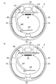
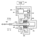
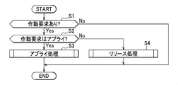
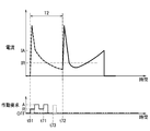
- FIG. 1 It is a block diagram of the vehicle provided with the electric parking brake control device which concerns on one Embodiment. It is a figure which shows the drum brake and the parking brake mechanism, and is the figure (a) which shows the state which a brake is not applied, and the figure (b) which shows the state which a brake is applied by a parking brake mechanism. It is sectional drawing which shows the electric actuator of the parking brake mechanism. It is a flowchart which shows the processing of a control part. It is a flowchart which shows the apply process. It is a flowchart which shows the release process. 6 is a time chart showing an example of the operation of the control unit when a new operation request received during the first predetermined time from the start of the apply process is a request for the apply process.
- the vehicle CR includes a drum brake D, a parking brake mechanism 200, and a vehicle brake fluid pressure control device 100.
- the drum brake D is provided on each of the four wheels W.
- the parking brake mechanism 200 is a mechanism for mechanically operating the drum brake D, and is provided for the drum brake D provided on the two rear wheels W.
- the vehicle brake fluid pressure control device 100 is for appropriately controlling the braking force applied to each wheel W of the vehicle CR.
- the vehicle brake fluid pressure control device 100 mainly includes a hydraulic pressure unit 10 provided with an oil passage (hydraulic passage) and various parts, and a control unit 20 for appropriately controlling various parts in the hydraulic pressure unit 10. Be prepared for.
- the hydraulic pressure unit 10 is connected to the master cylinder MC that generates brake hydraulic pressure by depressing the brake pedal BP via an oil passage, and is connected to the wheel cylinder D4 of each drum brake D via an oil passage. ..
- the hydraulic pressure unit 10 includes a valve, a pump, and the like for controlling the brake hydraulic pressure applied to the foil cylinder D4.
- the control unit 20 is an example of an electric parking brake control device.
- the control unit 20 has a function of controlling the drive and stop of the electric actuator 240 that operates the parking brake mechanism 200, and also has a function of controlling a valve or a pump in the hydraulic pressure unit 10.
- a wheel speed sensor 91 and a parking switch 92 are connected to the control unit 20.
- the wheel speed sensor 91 detects the wheel speed of the wheel W.
- the parking switch 92 is for switching the state of the parking brake mechanism 200 between the apply state and the release state.
- the apply state means a state in which the parking brake mechanism 200 generates a braking force.
- the release state means a state in which the parking brake mechanism 200 releases the braking force.
- the parking switch 92 can be switched between the apply position and the release position.
- the parking switch 92 outputs an apply signal for setting the parking brake mechanism 200 to the apply state when the parking switch 92 is located at the apply position, and releases the parking brake mechanism 200 when the parking brake mechanism 200 is located at the release position. Is output to the control unit 20.
- the control unit 20 includes, for example, a CPU, RAM, ROM, and an input / output circuit, and performs each arithmetic processing based on an input from a wheel speed sensor 91, a parking switch 92, or the like, and a program or data stored in the ROM. By doing so, control is performed.
- the drum brake D includes a drum D1 as an example of a rotating body, a brake shoe D2 as an example of a friction member, a return spring D3, and a wheel cylinder D4. I have.
- the drum D1 is a member having a cylindrical portion that rotates integrally with the wheel W.
- the brake shoe D2 is an arcuate member extending along the inner peripheral surface of the drum D1 and is pressed against the inner peripheral surface of the drum D1 to give a braking force to the wheel W.
- Two brake shoes D2 are provided along the inner peripheral surface of the drum D1. One end of each of the two brake shoes D2 is rotatably supported by the support member D5, so that the two brake shoes D2 can rotate in directions toward and away from each other.
- the return spring D3 is urging the other ends of the two brake shoes D2 in a direction to bring them closer to each other.
- the foil cylinder D4 urges the two brake shoes D2 toward the inner peripheral surface of the drum D1 by the brake hydraulic pressure supplied from the hydraulic pressure unit 10.
- the parking brake mechanism 200 includes a strut 210, a parking lever 220, a wire 230, and an electric actuator 240 shown in FIG.
- the strut 210 is engaged with the other end of each of the two brake shoes D2.
- One end of the parking lever 220 is rotatably supported by one brake shoe D2 by a pin 221.
- a wire 230 is connected to the other end of the parking lever 220. The portion between one end and the other end of the parking lever 220, which is closer to one end, is engaged with the strut 210.
- the parking lever 220 rotates about the pin 221 so that the parking lever 220 presses the other brake shoe D2 against the inner peripheral surface of the drum D1 via the strut 210. Further, when the wire 230 is pulled, the parking lever 220 rotates about the engagement portion with the strut 210, so that the parking lever 220 uses the pin 221 to move one brake shoe D2 to the inner peripheral surface of the drum D1. Press on.
- each brake shoe D2 is pressed against the inner peripheral surface of the drum D1 by the pulling operation of the wire 230.
- the wire 230 is loosened in the left direction in the drawing, each brake shoe D2 is separated from the inner peripheral surface of the drum D1 by the urging force of the return spring D3.
- the electric actuator 240 is a device for towing the wire 230.
- the electric actuator 240 includes a motor 241, a plurality of gears 242, a nut 243, a screw shaft 244, a housing 245, a retainer 246, and a plurality of disc springs 247.
- the nut 243 is connected to the motor 241 via a plurality of gears 242.
- the nut 243 has a female screw portion 243A that meshes with the male screw portion 244A of the screw shaft 244.
- the screw shaft 244 is supported by the housing 245 so as to be movable in the axial direction, and the wire 230 is fixed to the tip thereof.
- a flange portion 244B protruding in the radial direction is formed at an end portion of the screw shaft 244 opposite to the tip end.
- the retainer 246 is a member of a disk having a hole in the center, and is engaged with the flange portion 244B of the screw shaft 244 from the tip end side of the screw shaft 244.
- a plurality of disc springs 247 are arranged between the flange portion 244B and the nut 243 in the axial direction of the screw shaft 244.
- the position of the screw shaft 244 when the parking brake mechanism 200 is in the apply state is also referred to as an "apply position", and the position of the screw shaft 244 when the parking brake mechanism 200 is in the release state. Is also referred to as a "release position”. Specifically, the release position is the position shown in FIG. 3, and the apply position is the position where the screw shaft 244 shown in FIG. 3 is moved to the right side of the drawing from the position shown in the figure.
- the control unit 20 controls forward rotation, reverse rotation, and stop of the motor 241 based on the signal from the parking switch 92.
- the control unit 20 has a function of executing an apply process and a release process.
- the output of the apply signal from the parking switch 92 is also referred to as "request for apply processing”
- the output of the release signal from the parking switch 92 is also referred to as “request for release processing”. Requests are also collectively referred to as "operation requests”.
- the apply process is a process of driving the electric actuator 240 so that the parking brake mechanism 200 is in the apply state.
- the apply process is a process of controlling the electric actuator 240 so as to move the brake shoe D2 in the direction of pressing the brake shoe D2 against the drum D1.
- the control unit 20 rotates the motor 241 in the forward direction to move the screw shaft 244 to the apply position, thereby putting the parking brake mechanism 200 in the apply state.
- the control unit 20 when the control unit 20 receives the request (A) for the apply process, the control unit 20 starts the apply process by supplying a current for rotating the motor 241 in the forward direction to the motor 241. Time t1). An inrush current is generated when the motor 241 is energized, but the inrush current converges after a predetermined time (time t2). When the inrush current converges, the motor 241 begins to rotate.
- the screw shaft 244 starts moving from the release position to the apply position.
- the load applied from the disc spring 247 to the screw shaft 244 gradually decreases, so that the current gradually decreases.
- the screw shaft 244 is separated from the retainer 246, the load is not applied to the screw shaft 244 (time t3), and then the current becomes constant.
- the release process is a process of driving the electric actuator 240 so that the parking brake mechanism 200 is in the released state.
- the release process is a process of controlling the electric actuator 240 so as to move the brake shoe D2 away from the drum D1.
- the control unit 20 when the control unit 20 receives a request for release processing, the control unit 20 reversely rotates the motor 241 to move the screw shaft 244 to the release position, thereby putting the parking brake mechanism 200 in the release state.
- the control unit 20 when the control unit 20 receives the release processing request (R), the control unit 20 starts the release processing by supplying a current for rotating the motor 241 in the reverse direction to the motor 241 (). Time t51). When the energization of the motor 241 is started, an inrush current is generated, but the inrush current converges after a predetermined time (time t52). When the inrush current converges, the motor 241 begins to rotate.
- the screw shaft 244 moves from the apply position to the release position, and the brake shoe D2 moves away from the drum D1.
- the load applied from the brake shoe D2 to the screw shaft 244 gradually decreases, so that the current gradually decreases.
- the brake shoe D2 is separated from the drum D1, the load is not applied to the screw shaft 244 (time t53), and then the current becomes constant.
- the control unit 20 stops the energization and completes the release process.
- the control unit 20 can execute the operation change prohibition process and the operation change process during the apply process or the release process.
- the operation change prohibition process is a process in which the operation change of the electric actuator 240 based on a new operation request is not executed for a predetermined time from the start of the apply process or the release process.
- the control unit 20 when the apply process is started, the control unit 20 newly operates the electric actuator 240 for the first predetermined time T1 after the start of the apply process. Even if the request is received, the operation change of the electric actuator 240 based on the new operation request is not executed.
- the first predetermined time T1 is longer than the time T11 from the start of the apply process to the start of operation of the electric actuator 240, and from the start of the apply process to the contact of the brake shoe D2 with the drum D1.
- the time is set to be shorter than the time T12.
- the control unit 20 when the release process is started, the control unit 20 requests a new operation for operating the electric actuator 240 during the second predetermined time T2 after the release process is started. Even if it receives, the operation change of the electric actuator 240 based on the new operation request is not executed.
- the second predetermined time T2 is longer than the time T21 from the start of the release process to the start of operation of the electric actuator 240, and the time from the start of the release process until the brake shoe D2 separates from the drum D1. It is set to a shorter time than T22.
- the operation change processing after a predetermined time has elapsed from the start of the apply processing or the release processing, more specifically, after the operation change prohibition processing is completed, the operation change of the electric actuator 240 based on the new operation request is performed in response to the new operation request.
- This is the process to be executed. Specifically, when the control unit 20 starts the apply process, as shown in FIG. 8, after the lapse of the first predetermined time T1 from the start of the apply process, the control unit 20 of the electric actuator 240 based on the new operation request. The operation change is executed in response to a new operation request.
- control unit 20 operates the electric actuator 240 based on a new operation request after the second predetermined time T2 has elapsed from the start of the release process, as shown in FIG. Make changes in response to new actuation requests.
- the control unit 20 has a function of determining whether or not to execute the operation change process in response to a new operation request received during the operation change prohibition process. Specifically, the control unit 20 executes the operation change process when the new operation request received during the operation change prohibition process is different from the process currently being executed (see FIG. 8 and the like). Further, when the new operation request received during the operation change prohibition process is the same process as the process currently being executed, the control unit 20 does not execute the operation change process but performs the process currently being executed. Continue (see Fig. 7 etc.).
- control unit 20 when a plurality of new operation requests are received during the operation change prohibition process, the control unit 20 is based on the operation request last received among the plurality of new operation requests after the operation change prohibition process. , It is configured to control the electric actuator 240. Further, when the control unit 20 does not execute the operation change processing after the operation change prohibition processing and receives a new operation request between the end of the operation change prohibition processing and the completion of the processing. Is configured to control the motorized actuator 240 based on new actuation requirements.
- the control unit 20 when the new operation request received between the end of the operation change prohibition process and the completion of the process is different from the process currently being executed, the control unit 20 is new. Immediately after receiving the operation request, the operation change of the electric actuator 240 based on the new operation request is executed. Further, when the new operation request received from the end of the operation change prohibition process to the completion of the process is the same process as the process currently being executed, the control unit 20 changes the operation of the electric actuator 240. Continues the processing currently being executed without executing.
- control unit 20 constantly and repeatedly executes the process shown in FIG.
- control unit 20 first determines whether or not there is an operation request for operating the electric actuator 240 (S1). If it is determined in step S1 that there is no operation request (No), the control unit 20 ends this process.
- step S1 determines whether or not the operation request is a request for apply processing (S2). If it is determined in step S2 that the request is for the apply process (Yes), the control unit 20 executes the apply process (S3).
- step S2 If it is determined in step S2 that the request is not an apply process (No), the control unit 20 executes the release process (S4). After step S3 or step S4, the control unit 20 ends this process.
- the control unit 20 first starts energization for the apply process (S11). Specifically, in step S11, the control unit 20 supplies the motor 241 with a current for rotating the motor 241 in the forward direction.
- the control unit 20 determines whether or not the current after the first time T13 (see FIG. 7) has elapsed from the start of the apply process is equal to or higher than the apply threshold value IA (S12). Specifically, in step S12, the control unit 20 satisfies both the condition that the first time T13 has elapsed from the start of the apply process and the condition that the current becomes equal to or higher than the apply threshold value IA. Is determined.
- the first time T13 is the time from the start of the apply process to the time after the inrush current generated at the start has converged until the current becomes sufficiently smaller than the apply threshold value IA, and is an experiment or a simulation. It is set appropriately by such factors.
- step S12 determines whether or not the current after the lapse of the first time T13 is not equal to or higher than the apply threshold value IA (No)
- the control unit 20 determines whether or not the first predetermined time T1 has elapsed from the start of the apply process. (S13). If it is determined in step S13 that the first predetermined time T1 has not elapsed (No), the control unit 20 determines whether or not there is a new operation request (S14).
- step S14 If it is determined in step S14 that there is a new operation request (Yes), the control unit 20 stores the new operation request (S15). After step S15, or when it is determined in step S14 that there is no new operation request (No), the control unit 20 returns to the process of step S12.
- step S16 it is determined whether or not there is a new operation request during the first predetermined time T1 (S16). If it is determined in step S16 that there is a new operation request (Yes), the control unit 20 determines whether or not the new operation request is a request for release processing (S17). Specifically, when there is one new operation request received during the first predetermined time T1, the control unit 20 determines whether or not the operation request is a request for release processing (S17). Further, when the control unit 20 receives a plurality of operation requests during the first predetermined time T1, whether or not the last operation request received among the plurality of new operation requests is a release processing request. Is determined (S17).
- any method may be used as a method for specifying the last received operation request from a plurality of new operation requests.
- a new operation request and a plurality of times when the operation request is received may be stored in association with each other, and the last operation request received may be specified based on the time.
- the last received operation request may be specified by overwriting the new operation request with the new operation request stored last time.
- the stored new operation request may be reset, for example, at the start of the apply process or the release process.
- step S17 If it is determined in step S17 that the new operation request is a request for release processing (Yes), the control unit 20 executes release processing (S18) and ends this processing. If No is determined in step S16 or step S17, the control unit 20 determines whether or not a new release processing request has been received after the lapse of the first predetermined time T1 (S19).
- step S19 If it is determined in step S19 that a new release request has been received (Yes), the control unit 20 executes a release process (S18) and ends this process. If it is determined in step S19 that a new release request has not been received (No), the control unit 20 returns to the process of step S12 and determines whether or not the application process is completed.
- step S12 If it is determined in step S12 that the current after the lapse of the first time T13 has exceeded the apply threshold value IA (Yes), the control unit 20 turns off the energization (S20) and ends this process.
- the control unit 20 first starts energization for the release process (S31). Specifically, in step S31, the control unit 20 supplies the motor 241 with a current for rotating the motor 241 in the reverse direction.
- the control unit 20 determines whether or not the current after the second time T23 (see FIG. 10) has elapsed from the start of the release process has reached the release threshold IR or higher (S32). Specifically, in step S32, the control unit 20 satisfies both the condition that the second time T23 has elapsed from the start of the release process and the condition that the current becomes equal to or higher than the release threshold IR. Is determined.
- the second time T23 is the time from the start of the release process to the time after the inrush current generated at the start has converged until the current becomes sufficiently smaller than the release threshold IR, and is an experiment or a simulation. It is set appropriately by such factors.
- step S32 determines whether or not the current after the lapse of the second time T23 is not equal to or greater than the release threshold IR (No)
- the control unit 20 determines whether or not the second predetermined time T2 has elapsed from the start of the release process. (S33). If it is determined in step S33 that the second predetermined time T2 has not elapsed (No), the control unit 20 determines whether or not there is a new operation request (S34).
- step S34 If it is determined in step S34 that there is a new operation request (Yes), the control unit 20 stores the new operation request (S35). After step S35 or when it is determined in step S34 that there is no new operation request (No), the control unit 20 returns to the process of step S32.
- step S36 determines whether or not there is a new operation request during the second predetermined time T2 (S36). If it is determined in step S36 that there is a new operation request (Yes), the control unit 20 determines whether or not the new operation request is a request for apply processing (S37). Specifically, when there is one new operation request received during the second predetermined time T2, the control unit 20 determines whether or not the operation request is a request for apply processing (S37). Further, when the control unit 20 receives a plurality of operation requests during the second predetermined time T2, whether or not the last operation request received among the plurality of new operation requests is a request for apply processing. Is determined (S37).
- the method of specifying the last received operation request from a plurality of new operation requests and the method of resetting the new operation request may be performed by the same method as the apply process.
- step S37 If it is determined in step S37 that the new operation request is a request for the apply process (Yes), the control unit 20 executes the apply process (S38) and ends this process. If No is determined in step S36 or S37, the control unit 20 determines whether or not a new apply processing request has been received after the lapse of the second predetermined time T2 (S39).
- step S39 If it is determined in step S39 that a new apply request has been received (Yes), the control unit 20 executes the apply process (S38) and ends this process. If it is determined in step S39 that a new apply request has not been received (No), the control unit 20 returns to the process of step S32 and determines whether or not the release process is completed.
- step S32 If it is determined in step S32 that the current after the lapse of the second time T23 is equal to or higher than the release threshold IR (Yes), the control unit 20 turns off the energization (S40) and ends this process.
- the control unit 20 when the control unit 20 receives the request (A) for the apply process, the control unit 20 starts the apply process (time t1).
- the apply processing request (A) time t11
- the control unit 20 does not start a new apply process based on the request for a new apply process (A), and continues the currently executing apply process. ..
- the control unit 20 does not start a new apply process based on the request for a new apply process (A) even after the lapse of the first predetermined time T1 (time t12), and continues the currently executing apply process.
- the control unit 20 does not receive a new operation request during the first predetermined time T1 and receives a new apply processing request after the lapse of the first predetermined time T1. , Continues the currently executing apply process without starting a new apply process based on the request of the new apply process.
- the control unit 20 cancels the currently executing apply process and executes the release process (time t22). Further, during the first predetermined time T1, as shown by the two-dot chain line in the figure, even when only one release processing request (R) is received as a new operation request (time t23), the control unit 20 Cancels the currently executing apply process and executes the release process after the lapse of the first predetermined time T1 (time t22).
- the control unit 20 when a new operation request (R) is received after the lapse of the first predetermined time T1 without receiving a new operation request during the first predetermined time T1, the control unit 20 immediately stops the apply process and executes the release process (time t31).
- the control unit 20 when the control unit 20 receives the release processing request (R), the control unit 20 starts the release processing (time t51).
- the second predetermined time T2 as shown by the solid line in the figure, when a plurality of new operation requests are received and the last operation request received is the release processing request (R) (time t61).
- the control unit 20 does not start a new release process based on a new release process request (R) even after the second predetermined time T2 has elapsed (time t62), and continues the currently executing release process. ..
- the control unit 20 does not start a new release process based on a new release process request (R) even after the second predetermined time T2 has elapsed (time t62), and continues the currently executing release process.
- the control unit 20 does not receive a new operation request during the second predetermined time T2, and also receives a new release processing request after the lapse of the second predetermined time T2. , Continues the currently running release process without starting a new release process based on the new release process request (R).
- the control unit 20 cancels the release process currently being executed and executes the apply process (time t72). Further, during the second predetermined time T2, as shown by the two-dot chain line in the figure, even when only one request for apply processing (A) is received as a new operation request (time t73), the control unit 20 Cancels the release process currently being executed and executes the apply process after the lapse of the second predetermined time T2 (time t72).
- the control unit 20 when a new operation request (A) is received after the lapse of the second predetermined time T2 without receiving a new operation request during the second predetermined time T2, the control unit 20 immediately stops the release process and executes the apply process (time t81).
- the following effects can be obtained in the present embodiment.
- the first predetermined time T1 is set to a time shorter than the time T12 from the start of the apply process to the contact of the brake shoe D2 with the drum D1
- a new operation request is received.
- the time from the time until the process based on the new operation request is executed can be shortened, and the responsiveness of the electric actuator 240 to the new operation request received during the apply process can be improved.
- an inrush current is generated before the start of the operation of the electric actuator 240.
- the new operation request is not executed during this period, it is possible to suppress the inrush current at the start of the release process based on the new operation request from overlapping with the inrush current at the start of the apply process, and by extension, the electric motor.
- the operation of the actuator 240 can be accurately determined.
- the operation change process is executed before the currently executed process is completed. , It is possible to promptly respond to the user's request.
- the electric actuator 240 Since the electric actuator 240 is controlled based on the operation request received last among the plurality of new operation requests received during the operation change prohibition process, the electric actuator 240 can be controlled so as to correspond to the intention of the user. can.
- the embodiment can be transformed into various forms as illustrated below.
- control unit 20 of the vehicle brake hydraulic pressure control device 100 is exemplified as the electric parking brake control device, but a control device different from the vehicle brake hydraulic pressure control device, for example, an ECU (Electronic Control Unit) of the vehicle is exemplified. ) May be used as an electric parking brake control device.
- ECU Electronic Control Unit
- the parking brake mechanism 200 installed on the drum brake D is exemplified, but for example, the parking brake mechanism installed on the disc brake may be used.
- the rotor that rotates integrally with the wheel corresponds to the rotating body, and the pad pressed against the rotor corresponds to the friction member.
Landscapes
- Engineering & Computer Science (AREA)
- Transportation (AREA)
- Mechanical Engineering (AREA)
- Regulating Braking Force (AREA)
- Braking Systems And Boosters (AREA)
Abstract
アプライ処理等の実行中に受けた新たな作動要求に対する電動アクチュエータの応答性を高くし、電動アクチュエータの動作判定を正確に行う電動パーキングブレーキ制御装置を開示する。電動パーキングブレーキ制御装置は、車輪と一体回転する回転体に対して摩擦部材を押し付けるアプライ処理と、回転体から摩擦部材を離すリリース処理と、アプライ処理の開始から所定時間(T1)の間、新たな作動要求を受けても、新たな作動要求に基づく電動アクチュエータの動作変更を実行しない動作変更禁止処理と、アプライ処理の開始から所定時間(T1)の経過後に、新たな作動要求に基づく電動アクチュエータの動作変更を実行する動作変更処理を実行可能である。所定時間(T1)は、アプライ処理の開始から電動アクチュエータが動作し始めるまでの時間(T11)よりも長く、アプライ処理の開始から摩擦部材が回転体に接触するまでの時間(T12)よりも短い。
Description
本開示は、車輪と一体に回転する回転体に対して摩擦部材を押し付ける方向と離す方向に移動させるように電動アクチュエータを制御する電動パーキングブレーキ制御装置に関する。
従来、電動パーキングブレーキ制御装置として、回転体であるロータに対して摩擦部材であるパッドを押し付ける方向に移動させるように電動アクチュエータを制御するアプライ処理と、ロータからパッドを離す方向に移動させるように電動アクチュエータを制御するリリース処理と、を実行可能なものが知られている(特許第6466473号公報参照)。具体的に、この技術では、電動パーキングブレーキ制御装置は、アプライ処理の実行中において、パッドとロータが当接する前に、リリース処理の要求を受けると、パッドとロータが当接するまではリリース処理を実行せず、パッドとロータが当接した後に、リリース処理を実行する。
また、電動パーキングブレーキ制御装置は、リリース処理の実行中において、パッドがロータから離間する前に、アプライ処理の要求を受けると、パッドとロータが離間するまではアプライ処理を実行せず、パッドとロータが離間した後に、アプライ処理を実行する。
従来技術では、所定の処理(アプライ処理またはリリース処理)中において新たな作動要求(リリース要求またはアプライ要求)がなされても、パッドとロータが当接または離間するまでは、新たな作動要求に基づく処理が実行されないため、新たな作動要求から処理の実行まで時間がかかって応答性が悪くなるおそれがある。一方、応答性を高くするために、所定の処理中に新たな作動要求を受けるとすぐに新たな作動要求に基づく処理を実行する場合には、例えば所定の処理の開始時に発生する突入電流と、新たな作動要求に基づく処理の開始時に発生する突入電流が重なってしまい、電動アクチュエータの動作判定を正確に行えなくなるおそれがある。
アプライ処理またはリリース処理中に受けた新たな作動要求に対する電動アクチュエータの応答性を高くすることができるとともに、電動アクチュエータの動作判定を正確に行うことができる電動パーキングブレーキ制御装置を提供することが望まれている。
上述の背景に鑑み、車輪と一体に回転する回転体に対して摩擦部材を押し付ける方向に移動させるように電動アクチュエータを制御するアプライ処理と、前記回転体から前記摩擦部材を離す方向に移動させるように前記電動アクチュエータを制御するリリース処理と、を実行可能である電動パーキングブレーキ制御装置を開示する。
前記電動パーキングブレーキ制御装置は、前記アプライ処理を開始してから第1所定時間の間、前記電動アクチュエータを作動させるための新たな作動要求を受けても、当該新たな作動要求に基づく前記電動アクチュエータの動作変更を実行しない動作変更禁止処理と、前記アプライ処理を開始してから前記第1所定時間の経過後に、前記新たな作動要求に基づく前記電動アクチュエータの動作変更を、前記新たな作動要求に応じて実行する動作変更処理と、を実行可能である。
前記第1所定時間は、前記アプライ処理を開始してから、前記電動アクチュエータが動作し始めるまでの時間よりも長く、かつ、前記アプライ処理を開始してから前記摩擦部材が前記回転体に接触するまでの時間よりも短い時間に設定されている。
この構成によれば、第1所定時間がアプライ処理を開始してから摩擦部材が回転体に接触するまでの時間よりも短い時間に設定されているので、新たな作動要求を受けてから新たな作動要求に基づく処理を実行するまでの時間を短くすることができ、アプライ処理中に受けた新たな作動要求に対する電動アクチュエータの応答性を高くすることができる。また、第1所定時間を、アプライ処理を開始してから、電動アクチュエータが動作し始めるまでの時間よりも長い時間に設定することで、電動アクチュエータの動作開始前において突入電流が発生している間は、新たな作動要求が実行されないので、アプライ処理開始時の突入電流に、新たな作動要求に基づく処理開始時の突入電流が重なるのを抑制することができ、ひいては、電動アクチュエータの動作判定を正確に行うことができる。
また、本開示に係る電動パーキングブレーキ制御装置は、車輪と一体に回転する回転体に対して摩擦部材を押し付ける方向に移動させるように電動アクチュエータを制御するアプライ処理と、前記回転体から前記摩擦部材を離す方向に移動させるように前記電動アクチュエータを制御するリリース処理と、を実行可能である。
前記電動パーキングブレーキ制御装置は、前記リリース処理を開始してから第2所定時間の間、前記電動アクチュエータを作動させるための新たな作動要求を受けても、当該新たな作動要求に基づく前記電動アクチュエータの動作変更を実行しない動作変更禁止処理と、前記リリース処理を開始してから前記第2所定時間の経過後に、前記新たな作動要求に基づく前記電動アクチュエータの動作変更を、前記新たな作動要求に応じて実行する動作変更処理と、を実行可能である。
前記第2所定時間は、前記リリース処理を開始してから、前記電動アクチュエータが動作し始めるまでの時間よりも長く、かつ、前記リリース処理を開始してから前記摩擦部材が前記回転体から離れるまでの時間よりも短い時間に設定されている。
この構成によれば、第2所定時間がリリース処理を開始してから摩擦部材が回転体から離れるまでの時間よりも短い時間に設定されているので、新たな作動要求を受けてから新たな作動要求に基づく処理を実行するまでの時間を短くすることができ、リリース処理中に受けた新たな作動要求に対する電動アクチュエータの応答性を高くすることができる。また、第2所定時間を、リリース処理を開始してから、電動アクチュエータが動作し始めるまでの時間よりも長い時間に設定することで、電動アクチュエータの動作開始前において突入電流が発生している間は、新たな作動要求が実行されないので、リリース処理開始時の突入電流に、新たな作動要求に基づく処理開始時の突入電流が重なるのを抑制することができ、ひいては、電動アクチュエータの動作判定を正確に行うことができる。
また、前記電動パーキングブレーキ制御装置は、前記動作変更禁止処理中に受けた新たな作動要求が、現在実行中の処理と異なる処理である場合には、前記動作変更処理を実行してもよい。
この構成によれば、動作変更禁止処理中において、現在実行中の処理とは異なる処理を実行するための新たな作動要求がなされた場合には、現在実行中の処理が完了する前に動作変更処理が実行されるので、ユーザの要求に速やかに応えることができる。
また、前記電動パーキングブレーキ制御装置は、前記動作変更禁止処理中に受けた新たな作動要求が、現在実行中の処理と同じ処理である場合には、前記動作変更処理を実行せずに、現在実行中の処理を継続させてもよい。
この構成によれば、動作変更禁止処理中において、現在実行中の処理と同じ処理を実行するための新たな作動要求がなされた場合には、動作変更処理を実行せずに、現在実行中の処理を継続させるので、新たに同じ処理を開始し直すことなく、実行中の処理を滞りなく完了させることができる。
また、前記電動パーキングブレーキ制御装置は、前記動作変更禁止処理中に複数の新たな作動要求を受けた場合には、前記動作変更禁止処理の後に、前記複数の新たな作動要求のうち最後に受けた作動要求に基づいて、前記電動アクチュエータを制御してもよい。
この構成によれば、動作変更禁止処理中において受けた複数の新たな作動要求のうち最後に受けた作動要求に基づいて電動アクチュエータが制御されるので、ユーザの意思に対応するように電動アクチュエータを制御することができる。
電動パーキングブレーキ制御装置の一実施形態について、適宜図面を参照しながら詳細に説明する。
図1に示すように、車両CRは、ドラムブレーキDと、パーキングブレーキ機構200と、車両用ブレーキ液圧制御装置100とを備えている。
図1に示すように、車両CRは、ドラムブレーキDと、パーキングブレーキ機構200と、車両用ブレーキ液圧制御装置100とを備えている。
ドラムブレーキDは、4つの車輪Wにそれぞれ設けられている。パーキングブレーキ機構200は、ドラムブレーキDを機械的に動作させる機構であり、後側の2つの車輪Wに設けられたドラムブレーキDに対して設けられている。
車両用ブレーキ液圧制御装置100は、車両CRの各車輪Wに付与する制動力を適宜制御するためのものである。車両用ブレーキ液圧制御装置100は、油路(液圧路)や各種部品が設けられた液圧ユニット10と、液圧ユニット10内の各種部品を適宜制御するための制御部20とを主に備えている。液圧ユニット10は、ブレーキペダルBPの踏み込みによりブレーキ液圧を発生するマスタシリンダMCに油路を介して接続されるとともに、各ドラムブレーキDのホイルシリンダD4に油路を介して接続されている。液圧ユニット10は、ホイルシリンダD4に付与されるブレーキ液圧を制御するための弁やポンプなどを備えている。
制御部20は、電動パーキングブレーキ制御装置の一例である。制御部20は、パーキングブレーキ機構200を動作させる電動アクチュエータ240の駆動および停止を制御する機能を有する他、液圧ユニット10内の弁やポンプを制御する機能を有している。制御部20には、車輪速センサ91と、パーキングスイッチ92とが接続されている。車輪速センサ91は、車輪Wの車輪速度を検出する。パーキングスイッチ92は、パーキングブレーキ機構200の状態をアプライ状態とリリース状態とに切り替えるためのものである。ここで、アプライ状態とは、パーキングブレーキ機構200が制動力を発生させる状態をいう。また、リリース状態とは、パーキングブレーキ機構200が制動力を解除する状態をいう。
パーキングスイッチ92は、アプライ位置とリリース位置とに切替可能となっている。パーキングスイッチ92は、アプライ位置に位置するときにパーキングブレーキ機構200をアプライ状態にするためのアプライ信号を制御部20に出力し、リリース位置に位置するときにパーキングブレーキ機構200をリリース状態にするためのリリース信号を制御部20に出力する。
制御部20は、例えば、CPU、RAM、ROMおよび入出力回路を備えており、車輪速センサ91やパーキングスイッチ92などからの入力と、ROMに記憶されたプログラムやデータに基づいて各演算処理を行うことによって、制御を実行する。
図2(a),(b)に示すように、ドラムブレーキDは、回転体の一例としてのドラムD1と、摩擦部材の一例としてのブレーキシューD2と、リターンスプリングD3と、ホイルシリンダD4とを備えている。ドラムD1は、車輪Wと一体に回転する円筒状の部位を有する部材である。
ブレーキシューD2は、ドラムD1の内周面に沿って延びる円弧状の部材であり、ドラムD1の内周面に押し付けられることで、車輪Wに制動力を与える。ブレーキシューD2は、ドラムD1の内周面に沿って2つ設けられている。2つのブレーキシューD2は、それぞれ一端部が支持部材D5によって回動可能に支持されることで、互いに近づく方向と離れる方向に回動可能となっている。
リターンスプリングD3は、2つのブレーキシューD2の他端部を互いに近づける方向に付勢している。ホイルシリンダD4は、液圧ユニット10から供給されるブレーキ液圧によって、2つのブレーキシューD2をドラムD1の内周面に向けて付勢する。
パーキングブレーキ機構200は、ストラット210と、パーキングレバー220と、ワイヤ230と、図3に示す電動アクチュエータ240とを備えている。ストラット210は、2つのブレーキシューD2のそれぞれの他端部に係合している。
パーキングレバー220の一端部は、一方のブレーキシューD2にピン221によって回動可能に支持されている。パーキングレバー220の他端部には、ワイヤ230が連結されている。パーキングレバー220の一端部と他端部の間の部位であって、一端部寄りの部位は、ストラット210に係合している。
ワイヤ230が図示右方向に引っ張られると、パーキングレバー220がピン221を中心に回動することで、パーキングレバー220がストラット210を介して他方のブレーキシューD2をドラムD1の内周面に押し付ける。さらに、ワイヤ230が引っ張られると、パーキングレバー220がストラット210との係合部分を中心に回動することで、パーキングレバー220がピン221を介して一方のブレーキシューD2をドラムD1の内周面に押し付ける。
これにより、ワイヤ230の引張動作によって、各ブレーキシューD2がドラムD1の内周面に押し付けられる。なお、ワイヤ230を図示左方向に緩めると、リターンスプリングD3の付勢力によって、各ブレーキシューD2がドラムD1の内周面から離れる。
図3に示すように、電動アクチュエータ240は、ワイヤ230を牽引するための装置である。電動アクチュエータ240は、モータ241と、複数のギヤ242と、ナット243と、ネジ軸244と、ハウジング245と、リテーナ246と、複数の皿バネ247とを備えている。
ナット243は、複数のギヤ242を介してモータ241に連結されている。ナット243は、ネジ軸244の雄ネジ部244Aと噛み合う雌ネジ部243Aを有している。ネジ軸244は、ハウジング245に軸方向に移動可能に支持されており、先端にワイヤ230が固定されている。ネジ軸244の先端とは反対側の端部には、径方向に突出する鍔部244Bが形成されている。
リテーナ246は、中心に穴を有する円板の部材であり、ネジ軸244の鍔部244Bにネジ軸244の先端側から係合している。複数の皿バネ247は、ネジ軸244の軸方向において、鍔部244Bとナット243の間に配置されている。
この電動アクチュエータ240では、モータ241を正回転させると、ネジ軸244がハウジング245内に収容される方向に移動することで、ワイヤ230が引っ張られ、パーキングブレーキ機構200が、パーキングブレーキの効いたアプライ状態となる。また、モータ241を逆回転させると、ネジ軸244がハウジング245から突出する方向に移動することで、ワイヤ230が緩められて、パーキングブレーキ機構200が、パーキングブレーキが解除されたリリース状態となる。なお、リリース状態においては、リテーナ246とナット243の間で、複数の皿バネ247が変形した状態で挟持されている。
以下の説明では、パーキングブレーキ機構200がアプライ状態となっているときのネジ軸244の位置を、「アプライ位置」とも称し、パーキングブレーキ機構200がリリース状態となっているときのネジ軸244の位置を、「リリース位置」とも称する。具体的に、リリース位置は、図3に示す位置であり、アプライ位置は、図3に示すネジ軸244が図の位置よりも図示右側に移動した位置である。
制御部20は、パーキングスイッチ92からの信号に基づいて、モータ241の正回転・逆回転・停止を制御している。制御部20は、アプライ処理と、リリース処理と、を実行する機能を有している。以下の説明では、パーキングスイッチ92からのアプライ信号の出力を、「アプライ処理の要求」とも称し、パーキングスイッチ92からのリリース信号の出力を、「リリース処理の要求」とも称し、これらの各処理の要求を総称して「作動要求」とも称する。
アプライ処理は、パーキングブレーキ機構200がアプライ状態となるように電動アクチュエータ240を駆動させる処理である。言い換えると、アプライ処理は、ドラムD1に対してブレーキシューD2を押し付ける方向に移動させるように電動アクチュエータ240を制御する処理である。具体的に、制御部20は、アプライ処理の要求を受けると、モータ241を正回転させてネジ軸244をアプライ位置まで移動させることで、パーキングブレーキ機構200をアプライ状態にする。
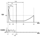
詳しくは、図7に示すように、制御部20は、アプライ処理の要求(A)を受けると、モータ241を正回転させるための電流をモータ241に供給することで、アプライ処理を開始する(時刻t1)。モータ241への通電開始時には、突入電流が発生するが、突入電流は所定時間後に収束する(時刻t2)。突入電流が収束すると、モータ241が回転し始める。
これにより、ネジ軸244がリリース位置からアプライ位置に向けて移動を開始する。ネジ軸244がリリース位置からアプライ位置に向けて移動していくと、皿バネ247からネジ軸244にかかる負荷が徐々に小さくなっていくため、電流は徐々に小さくなる。ネジ軸244がリテーナ246から離れると、ネジ軸244に負荷がかからなくなり(時刻t3)、その後、電流が一定となる。
その後、ブレーキシューD2がドラムD1に接触すると(時刻t4)、ネジ軸244にかかる負荷が徐々に大きくなっていき、モータ241に供給する電流が上昇していく。その後、制御部20は、電流がアプライ閾値IA以上になると(時刻t5)、通電を停止して、アプライ処理を完了させる。
リリース処理は、パーキングブレーキ機構200がリリース状態となるように電動アクチュエータ240を駆動させる処理である。言い換えると、リリース処理は、ドラムD1からブレーキシューD2を離す方向に移動させるように電動アクチュエータ240を制御する処理である。具体的に、制御部20は、リリース処理の要求を受けると、モータ241を逆回転させてネジ軸244をリリース位置まで移動させることで、パーキングブレーキ機構200をリリース状態にする。
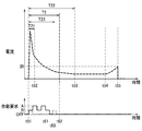
詳しくは、図10に示すように、制御部20は、リリース処理の要求(R)を受けると、モータ241を逆回転させるための電流をモータ241に供給することで、リリース処理を開始する(時刻t51)。モータ241への通電開始時には、突入電流が発生するが、突入電流は所定時間後に収束する(時刻t52)。突入電流が収束すると、モータ241が回転し始める。
これにより、ネジ軸244がアプライ位置からリリース位置に向けて移動していき、ブレーキシューD2がドラムD1から離れる方向に移動する。ネジ軸244がアプライ位置からリリース位置に向けて移動していくと、ブレーキシューD2からネジ軸244にかかる負荷が徐々に小さくなっていくため、電流は徐々に小さくなる。ブレーキシューD2がドラムD1から離間すると、ネジ軸244に負荷がかからなくなり(時刻t53)、その後、電流が一定となる。
その後、ネジ軸244がリテーナ246に接触すると(時刻t54)、皿バネ247からネジ軸244にかかる負荷が徐々に大きくなっていき、モータ241に供給する電流が上昇していく。その後、制御部20は、電流がリリース閾値IR以上になると(時刻t55)、通電を停止して、リリース処理を完了させる。
制御部20は、アプライ処理中またはリリース処理中において、動作変更禁止処理と、動作変更処理と、を実行可能となっている。動作変更禁止処理は、アプライ処理またはリリース処理の開始から所定時間の間、新たな作動要求に基づく電動アクチュエータ240の動作変更を実行しない処理である。
詳しくは、制御部20は、図7に示すように、アプライ処理を開始した場合には、アプライ処理を開始してから第1所定時間T1の間、電動アクチュエータ240を作動させるための新たな作動要求を受けても、当該新たな作動要求に基づく電動アクチュエータ240の動作変更を実行しない。第1所定時間T1は、アプライ処理を開始してから、電動アクチュエータ240が動作し始めるまでの時間T11よりも長く、かつ、アプライ処理を開始してからブレーキシューD2がドラムD1に接触するまでの時間T12よりも短い時間に設定されている。
また、制御部20は、図10に示すように、リリース処理を開始した場合には、リリース処理を開始してから第2所定時間T2の間、電動アクチュエータ240を作動させるための新たな作動要求を受けても、当該新たな作動要求に基づく電動アクチュエータ240の動作変更を実行しない。第2所定時間T2は、リリース処理を開始してから、電動アクチュエータ240が動作し始めるまでの時間T21よりも長く、かつ、リリース処理を開始してからブレーキシューD2がドラムD1から離れるまでの時間T22よりも短い時間に設定されている。
動作変更処理は、アプライ処理またはリリース処理の開始から所定時間の経過後、詳しくは動作変更禁止処理の終了後に、新たな作動要求に基づく電動アクチュエータ240の動作変更を、新たな作動要求に応じて実行する処理である。詳しくは、制御部20は、アプライ処理を開始した場合には、図8に示すように、アプライ処理を開始してから第1所定時間T1の経過後に、新たな作動要求に基づく電動アクチュエータ240の動作変更を、新たな作動要求に応じて実行する。また、制御部20は、リリース処理を開始した場合には、図11に示すように、リリース処理を開始してから第2所定時間T2の経過後に、新たな作動要求に基づく電動アクチュエータ240の動作変更を、新たな作動要求に応じて実行する。
制御部20は、動作変更禁止処理中に受けた新たな作動要求に応じて、動作変更処理の実行の可否を決定する機能を有している。詳しくは、制御部20は、動作変更禁止処理中に受けた新たな作動要求が、現在実行中の処理と異なる処理である場合には、動作変更処理を実行する(図8等参照)。また、制御部20は、動作変更禁止処理中に受けた新たな作動要求が、現在実行中の処理と同じ処理である場合には、動作変更処理を実行せずに、現在実行中の処理を継続させる(図7等参照)。
また、制御部20は、動作変更禁止処理中に複数の新たな作動要求を受けた場合には、動作変更禁止処理の後に、複数の新たな作動要求のうち最後に受けた作動要求に基づいて、電動アクチュエータ240を制御するように構成されている。さらに、制御部20は、動作変更禁止処理の後に動作変更処理を実行しない場合であって、かつ、動作変更禁止処理の終了から処理が完了するまでの間に新たな作動要求を受けた場合には、新たな作動要求に基づいて電動アクチュエータ240を制御するように構成されている。
具体的には、制御部20は、動作変更禁止処理の終了から処理が完了するまでの間に受けた新たな作動要求が、現在実行中の処理とは異なる処理である場合には、新たな作動要求を受け付けた直後に、新たな作動要求に基づく電動アクチュエータ240の動作変更を実行する。また、制御部20は、動作変更禁止処理の終了から処理が完了するまでの間に受けた新たな作動要求が、現在実行中の処理と同じ処理である場合には、電動アクチュエータ240の動作変更を実行せずに、現在実行中の処理を継続させる。
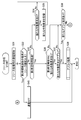
次に、制御部20の処理について、図4~図6を参照して詳細に説明する。制御部20は、図4に示す処理を常時繰り返し実行している。
図4の処理において、制御部20は、まず、電動アクチュエータ240を作動させるための作動要求があるか否かを判定する(S1)。ステップS1において作動要求がないと判定した場合には(No)、制御部20は、本処理を終了する。
ステップS1において作動要求があると判定した場合には(Yes)、制御部20は、作動要求がアプライ処理の要求であるか否かを判定する(S2)。ステップS2においてアプライ処理の要求であると判定した場合には(Yes)、制御部20は、アプライ処理を実行する(S3)。
ステップS2においてアプライ処理の要求でないと判定した場合には(No)、制御部20は、リリース処理を実行する(S4)。ステップS3またはステップS4の後、制御部20は、本処理を終了する。
図5に示すように、アプライ処理において、制御部20は、まず、アプライ処理用の通電を開始する(S11)。詳しくは、ステップS11において、制御部20は、モータ241を正回転させるための電流をモータ241に供給する。
ステップS11の後、制御部20は、アプライ処理の開始から第1時間T13(図7参照)が経過した後の電流がアプライ閾値IA以上になったか否かを判定する(S12)。具体的に、制御部20は、ステップS12において、アプライ処理の開始から第1時間T13が経過したという条件と、電流がアプライ閾値IA以上になったという条件とが、ともに満たされているか否かを判定する。ここで、第1時間T13は、アプライ処理を開始してから、開始時に発生した突入電流が収束した後であって、電流がアプライ閾値IAより充分に小さくなるまでの時間であり、実験やシミュレーション等により適宜設定されている。
ステップS12において第1時間T13経過後の電流がアプライ閾値IA以上でないと判定した場合には(No)、制御部20は、アプライ処理の開始から第1所定時間T1が経過したか否かを判定する(S13)。ステップS13において第1所定時間T1が経過していないと判定した場合には(No)、制御部20は、新たな作動要求があるか否かを判定する(S14)。
ステップS14において新たな作動要求があると判定した場合には(Yes)、制御部20は、新たな作動要求を記憶する(S15)。ステップS15の後、または、ステップS14において新たな作動要求がないと判定した場合には(No)、制御部20は、ステップS12の処理に戻る。
ステップS13において第1所定時間T1が経過したと判定した場合には(Yes)、第1所定時間T1の間において新たな作動要求があったか否かを判定する(S16)。ステップS16において新たな作動要求があったと判定した場合には(Yes)、制御部20は、新たな作動要求がリリース処理の要求であるか否かを判定する(S17)。詳しくは、制御部20は、第1所定時間T1の間に受けた新たな作動要求が1つの場合には、当該作動要求がリリース処理の要求であるか否かを判定する(S17)。また、制御部20は、第1所定時間T1の間に複数の作動要求を受けた場合には、複数の新たな作動要求のうち最後に受けた作動要求がリリース処理の要求であるか否かを判定する(S17)。
なお、複数の新たな作動要求の中から最後に受けた作動要求を特定する方法としては、どのような方法であってもよい。例えば、ステップS15において、新たな作動要求と当該作動要求を受信した時刻を対応づけて複数記憶していき、時刻に基づいて最後に受けた作動要求を特定してもよい。また、ステップS15において、新たな作動要求を、前回記憶した新たな作動要求に上書きしていくことで、最後に受けた作動要求を特定してもよい。なお、記憶した新たな作動要求は、例えば、アプライ処理の開始時またはリリース処理の開始時にリセットすればよい。
ステップS17において新たな作動要求がリリース処理の要求であると判定した場合には(Yes)、制御部20は、リリース処理を実行して(S18)、本処理を終了する。また、ステップS16またはステップS17においてNoと判定した場合には、制御部20は、第1所定時間T1の経過後において、新たなリリース処理の要求を受けたか否かを判定する(S19)。
ステップS19において新たなリリース要求を受けたと判定した場合には(Yes)、制御部20は、リリース処理を実行して(S18)、本処理を終了する。ステップS19において新たなリリース要求を受けていないと判定した場合には(No)、制御部20は、ステップS12の処理に戻って、アプライ処理の完了の適否を判定する。
ステップS12において第1時間T13経過後の電流がアプライ閾値IA以上になったと判定した場合には(Yes)、制御部20は、通電をOFFにして(S20)、本処理を終了する。
図6に示すように、リリース処理において、制御部20は、まず、リリース処理用の通電を開始する(S31)。詳しくは、ステップS31において、制御部20は、モータ241を逆回転させるための電流をモータ241に供給する。
ステップS31の後、制御部20は、リリース処理の開始から第2時間T23(図10参照)が経過した後の電流がリリース閾値IR以上になったか否かを判定する(S32)。具体的に、制御部20は、ステップS32において、リリース処理の開始から第2時間T23が経過したという条件と、電流がリリース閾値IR以上になったという条件とが、ともに満たされているか否かを判定する。ここで、第2時間T23は、リリース処理を開始してから、開始時に発生した突入電流が収束した後であって、電流がリリース閾値IRより充分に小さくなるまでの時間であり、実験やシミュレーション等により適宜設定されている。
ステップS32において第2時間T23経過後の電流がリリース閾値IR以上でないと判定した場合には(No)、制御部20は、リリース処理の開始から第2所定時間T2が経過したか否かを判定する(S33)。ステップS33において第2所定時間T2が経過していないと判定した場合には(No)、制御部20は、新たな作動要求があるか否かを判定する(S34)。
ステップS34において新たな作動要求があると判定した場合には(Yes)、制御部20は、新たな作動要求を記憶する(S35)。ステップS35の後、または、ステップS34において新たな作動要求がないと判定した場合には(No)、制御部20は、ステップS32の処理に戻る。
ステップS33において第2所定時間T2が経過したと判定した場合には(Yes)、第2所定時間T2の間において新たな作動要求があったか否かを判定する(S36)。ステップS36において新たな作動要求があったと判定した場合には(Yes)、制御部20は、新たな作動要求がアプライ処理の要求であるか否かを判定する(S37)。詳しくは、制御部20は、第2所定時間T2の間に受けた新たな作動要求が1つの場合には、当該作動要求がアプライ処理の要求であるか否かを判定する(S37)。また、制御部20は、第2所定時間T2の間に複数の作動要求を受けた場合には、複数の新たな作動要求のうち最後に受けた作動要求がアプライ処理の要求であるか否かを判定する(S37)。
なお、複数の新たな作動要求の中から最後に受けた作動要求を特定する方法や新たな作動要求をリセットする方法は、アプライ処理と同様の方法で行えばよい。
ステップS37において新たな作動要求がアプライ処理の要求であると判定した場合には(Yes)、制御部20は、アプライ処理を実行して(S38)、本処理を終了する。また、ステップS36またはステップS37においてNoと判定した場合には、制御部20は、第2所定時間T2の経過後において、新たなアプライ処理の要求を受けたか否かを判定する(S39)。
ステップS39において新たなアプライ要求を受けたと判定した場合には(Yes)、制御部20は、アプライ処理を実行して(S38)、本処理を終了する。ステップS39において新たなアプライ要求を受けていないと判定した場合には(No)、制御部20は、ステップS32の処理に戻って、リリース処理の完了の適否を判定する。
ステップS32において第2時間T23経過後の電流がリリース閾値IR以上になったと判定した場合には(Yes)、制御部20は、通電をOFFにして(S40)、本処理を終了する。
次に、制御部20の動作の一例について、図7~図12を参照して詳細に説明する。
図7に示すように、制御部20は、アプライ処理の要求(A)を受けると、アプライ処理を開始する(時刻t1)。第1所定時間T1の間において、図に実線で示すように、複数の新たな作動要求を受け、最後に受けた作動要求がアプライ処理の要求(A)である場合には(時刻t11)、制御部20は、第1所定時間T1が経過しても(時刻t12)、新たなアプライ処理の要求(A)に基づく新たなアプライ処理を開始せずに、現在実行中のアプライ処理を継続する。また、第1所定時間T1の間において、図に2点鎖線で示すように、新たな作動要求としてアプライ処理(A)の要求を1つだけ受けた場合にも(時刻t13)、制御部20は、第1所定時間T1が経過しても(時刻t12)、新たなアプライ処理の要求(A)に基づく新たなアプライ処理を開始せずに、現在実行中のアプライ処理を継続する。なお、図示は省略するが、第1所定時間T1の間では新たな作動要求を受けずに、第1所定時間T1の経過後に新たなアプライ処理の要求を受けた場合にも、制御部20は、新たなアプライ処理の要求に基づく新たなアプライ処理を開始せずに、現在実行中のアプライ処理を継続する。
図7に示すように、制御部20は、アプライ処理の要求(A)を受けると、アプライ処理を開始する(時刻t1)。第1所定時間T1の間において、図に実線で示すように、複数の新たな作動要求を受け、最後に受けた作動要求がアプライ処理の要求(A)である場合には(時刻t11)、制御部20は、第1所定時間T1が経過しても(時刻t12)、新たなアプライ処理の要求(A)に基づく新たなアプライ処理を開始せずに、現在実行中のアプライ処理を継続する。また、第1所定時間T1の間において、図に2点鎖線で示すように、新たな作動要求としてアプライ処理(A)の要求を1つだけ受けた場合にも(時刻t13)、制御部20は、第1所定時間T1が経過しても(時刻t12)、新たなアプライ処理の要求(A)に基づく新たなアプライ処理を開始せずに、現在実行中のアプライ処理を継続する。なお、図示は省略するが、第1所定時間T1の間では新たな作動要求を受けずに、第1所定時間T1の経過後に新たなアプライ処理の要求を受けた場合にも、制御部20は、新たなアプライ処理の要求に基づく新たなアプライ処理を開始せずに、現在実行中のアプライ処理を継続する。
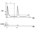
図8に示すように、第1所定時間T1の間において、図に実線で示すように、複数の新たな作動要求を受け、最後に受けた作動要求がリリース処理の要求(R)である場合には(時刻t21)、制御部20は、第1所定時間T1の経過後に、現在実行中のアプライ処理を中止してリリース処理を実行する(時刻t22)。また、第1所定時間T1の間において、図に2点鎖線で示すように、新たな作動要求としてリリース処理の要求(R)を1つだけ受けた場合にも(時刻t23)、制御部20は、第1所定時間T1の経過後に、現在実行中のアプライ処理を中止してリリース処理を実行する(時刻t22)。
図9に示すように、第1所定時間T1の間では新たな作動要求を受けずに、第1所定時間T1の経過後に新たなリリース処理の要求(R)を受けた場合には、制御部20は、即座にアプライ処理を中止してリリース処理を実行する(時刻t31)。
図10に示すように、制御部20は、リリース処理の要求(R)を受けると、リリース処理を開始する(時刻t51)。第2所定時間T2の間において、図に実線で示すように、複数の新たな作動要求を受け、最後に受けた作動要求がリリース処理の要求(R)である場合には(時刻t61)、制御部20は、第2所定時間T2が経過しても(時刻t62)、新たなリリース処理の要求(R)に基づく新たなリリース処理を開始せずに、現在実行中のリリース処理を継続する。また、第2所定時間T2の間において、図に2点鎖線で示すように、新たな作動要求としてリリース処理(R)の要求を1つだけ受けた場合にも(時刻t63)、制御部20は、第2所定時間T2が経過しても(時刻t62)、新たなリリース処理の要求(R)に基づく新たなリリース処理を開始せずに、現在実行中のリリース処理を継続する。なお、図示は省略するが、第2所定時間T2の間では新たな作動要求を受けずに、第2所定時間T2の経過後に新たなリリース処理の要求を受けた場合にも、制御部20は、新たなリリース処理の要求(R)に基づく新たなリリース処理を開始せずに、現在実行中のリリース処理を継続する。
図11に示すように、第2所定時間T2の間において、図に実線で示すように、複数の新たな作動要求を受け、最後に受けた作動要求がアプライ処理の要求(A)である場合には(時刻t71)、制御部20は、第2所定時間T2の経過後に、現在実行中のリリース処理を中止してアプライ処理を実行する(時刻t72)。また、第2所定時間T2の間において、図に2点鎖線で示すように、新たな作動要求としてアプライ処理の要求(A)を1つだけ受けた場合にも(時刻t73)、制御部20は、第2所定時間T2の経過後に、現在実行中のリリース処理を中止してアプライ処理を実行する(時刻t72)。
図12に示すように、第2所定時間T2の間では新たな作動要求を受けずに、第2所定時間T2の経過後に新たなアプライ処理の要求(A)を受けた場合には、制御部20は、即座にリリース処理を中止してアプライ処理を実行する(時刻t81)。
以上によれば、本実施形態において以下のような効果を得ることができる。
図7に示すように、第1所定時間T1がアプライ処理を開始してからブレーキシューD2がドラムD1に接触するまでの時間T12よりも短い時間に設定されているので、新たな作動要求を受けてから新たな作動要求に基づく処理を実行するまでの時間を短くすることができ、アプライ処理中に受けた新たな作動要求に対する電動アクチュエータ240の応答性を高くすることができる。また、第1所定時間T1を、アプライ処理を開始してから、電動アクチュエータ240が動作し始めるまでの時間T11よりも長い時間に設定することで、電動アクチュエータ240の動作開始前において突入電流が発生している間は、新たな作動要求が実行されないので、アプライ処理開始時の突入電流に、新たな作動要求に基づくリリース処理開始時の突入電流が重なるのを抑制することができ、ひいては、電動アクチュエータ240の動作判定を正確に行うことができる。
図7に示すように、第1所定時間T1がアプライ処理を開始してからブレーキシューD2がドラムD1に接触するまでの時間T12よりも短い時間に設定されているので、新たな作動要求を受けてから新たな作動要求に基づく処理を実行するまでの時間を短くすることができ、アプライ処理中に受けた新たな作動要求に対する電動アクチュエータ240の応答性を高くすることができる。また、第1所定時間T1を、アプライ処理を開始してから、電動アクチュエータ240が動作し始めるまでの時間T11よりも長い時間に設定することで、電動アクチュエータ240の動作開始前において突入電流が発生している間は、新たな作動要求が実行されないので、アプライ処理開始時の突入電流に、新たな作動要求に基づくリリース処理開始時の突入電流が重なるのを抑制することができ、ひいては、電動アクチュエータ240の動作判定を正確に行うことができる。
図10に示すように、第2所定時間T2がリリース処理を開始してからブレーキシューD2がドラムD1から離れるまでの時間T22よりも短い時間に設定されているので、新たな作動要求を受けてから新たな作動要求に基づく処理を実行するまでの時間を短くすることができ、リリース処理中に受けた新たな作動要求に対する電動アクチュエータ240の応答性を高くすることができる。また、第2所定時間T2を、リリース処理を開始してから、電動アクチュエータ240が動作し始めるまでの時間T21よりも長い時間に設定することで、電動アクチュエータ240の動作開始前において突入電流が発生している間は、新たな作動要求が実行されないので、リリース処理開始時の突入電流に、新たな作動要求に基づくアプライ処理開始時の突入電流が重なるのを抑制することができ、ひいては、電動アクチュエータ240の動作判定を正確に行うことができる。
動作変更禁止処理中において、現在実行中の処理とは異なる処理を実行するための新たな作動要求がなされた場合には、現在実行中の処理が完了する前に動作変更処理が実行されるので、ユーザの要求に速やかに応えることができる。
動作変更禁止処理中において、現在実行中の処理と同じ処理を実行するための新たな作動要求がなされた場合には、動作変更処理を実行せずに、現在実行中の処理を継続させるので、新たに同じ処理を開始し直すことなく、実行中の処理を滞りなく完了させることができる。
動作変更禁止処理中において受けた複数の新たな作動要求のうち最後に受けた作動要求に基づいて電動アクチュエータ240が制御されるので、ユーザの意思に対応するように電動アクチュエータ240を制御することができる。
なお、前記実施形態は、以下に例示するように様々な形態に変形して実施することができる。
前記実施形態では、電動パーキングブレーキ制御装置として車両用ブレーキ液圧制御装置100の制御部20を例示したが、車両用ブレーキ液圧制御装置とは別の制御装置、例えば車両のECU(Electronic Control Unit)を電動パーキングブレーキ制御装置としてもよい。
前記実施形態では、ドラムブレーキDに設置されるパーキングブレーキ機構200を例示したが、例えば、ディスクブレーキに設置されるパーキングブレーキ機構であってもよい。この場合、車輪と一体に回転するロータが回転体に相当し、ロータに押し付けられるパッドが摩擦部材に相当する。
前記した実施形態および変形例で説明した各要素を、任意に組み合わせて実施してもよい。
Claims (5)
- 車輪と一体に回転する回転体に対して摩擦部材を押し付ける方向に移動させるように電動アクチュエータを制御するアプライ処理と、前記回転体から前記摩擦部材を離す方向に移動させるように前記電動アクチュエータを制御するリリース処理と、を実行可能な電動パーキングブレーキ制御装置であって、
前記アプライ処理を開始してから第1所定時間の間、前記電動アクチュエータを作動させるための新たな作動要求を受けても、当該新たな作動要求に基づく前記電動アクチュエータの動作変更を実行しない動作変更禁止処理と、
前記アプライ処理を開始してから前記第1所定時間の経過後に、前記新たな作動要求に基づく前記電動アクチュエータの動作変更を、前記新たな作動要求に応じて実行する動作変更処理と、を実行可能であり、
前記第1所定時間は、前記アプライ処理を開始してから、前記電動アクチュエータが動作し始めるまでの時間よりも長く、かつ、前記アプライ処理を開始してから前記摩擦部材が前記回転体に接触するまでの時間よりも短い時間に設定されていることを特徴とする電動パーキングブレーキ制御装置。 - 車輪と一体に回転する回転体に対して摩擦部材を押し付ける方向に移動させるように電動アクチュエータを制御するアプライ処理と、前記回転体から前記摩擦部材を離す方向に移動させるように前記電動アクチュエータを制御するリリース処理と、を実行可能な電動パーキングブレーキ制御装置であって、
前記リリース処理を開始してから第2所定時間の間、前記電動アクチュエータを作動させるための新たな作動要求を受けても、当該新たな作動要求に基づく前記電動アクチュエータの動作変更を実行しない動作変更禁止処理と、
前記リリース処理を開始してから前記第2所定時間の経過後に、前記新たな作動要求に基づく前記電動アクチュエータの動作変更を、前記新たな作動要求に応じて実行する動作変更処理と、を実行可能であり、
前記第2所定時間は、前記リリース処理を開始してから、前記電動アクチュエータが動作し始めるまでの時間よりも長く、かつ、前記リリース処理を開始してから前記摩擦部材が前記回転体から離れるまでの時間よりも短い時間に設定されていることを特徴とする電動パーキングブレーキ制御装置。 - 前記動作変更禁止処理中に受けた新たな作動要求が、現在実行中の処理と異なる処理である場合には、前記動作変更処理を実行することを特徴とする請求項1または請求項2に記載の電動パーキングブレーキ制御装置。
- 前記動作変更禁止処理中に受けた新たな作動要求が、現在実行中の処理と同じ処理である場合には、前記動作変更処理を実行せずに、現在実行中の処理を継続させることを特徴とする請求項1から請求項3のいずれか1項に記載の電動パーキングブレーキ制御装置。
- 前記動作変更禁止処理中に複数の新たな作動要求を受けた場合には、前記動作変更禁止処理の後に、前記複数の新たな作動要求のうち最後に受けた作動要求に基づいて、前記電動アクチュエータを制御することを特徴とする請求項1から請求項4のいずれか1項に記載の電動パーキングブレーキ制御装置。
Priority Applications (1)
| Application Number | Priority Date | Filing Date | Title |
|---|---|---|---|
| JP2022535035A JP7431972B2 (ja) | 2020-07-07 | 2021-06-29 | 電動パーキングブレーキ制御装置 |
Applications Claiming Priority (2)
| Application Number | Priority Date | Filing Date | Title |
|---|---|---|---|
| JP2020117237 | 2020-07-07 | ||
| JP2020-117237 | 2020-07-07 |
Publications (1)
| Publication Number | Publication Date |
|---|---|
| WO2022009729A1 true WO2022009729A1 (ja) | 2022-01-13 |
Family
ID=79553066
Family Applications (1)
| Application Number | Title | Priority Date | Filing Date |
|---|---|---|---|
| PCT/JP2021/024497 Ceased WO2022009729A1 (ja) | 2020-07-07 | 2021-06-29 | 電動パーキングブレーキ制御装置 |
Country Status (2)
| Country | Link |
|---|---|
| JP (1) | JP7431972B2 (ja) |
| WO (1) | WO2022009729A1 (ja) |
Citations (2)
| Publication number | Priority date | Publication date | Assignee | Title |
|---|---|---|---|---|
| WO2016104680A1 (ja) * | 2014-12-27 | 2016-06-30 | マツダ株式会社 | ブレーキ装置 |
| JP2020069948A (ja) * | 2018-11-01 | 2020-05-07 | 日立オートモティブシステムズ株式会社 | 電動パーキングブレーキ装置 |
-
2021
- 2021-06-29 JP JP2022535035A patent/JP7431972B2/ja active Active
- 2021-06-29 WO PCT/JP2021/024497 patent/WO2022009729A1/ja not_active Ceased
Patent Citations (2)
| Publication number | Priority date | Publication date | Assignee | Title |
|---|---|---|---|---|
| WO2016104680A1 (ja) * | 2014-12-27 | 2016-06-30 | マツダ株式会社 | ブレーキ装置 |
| JP2020069948A (ja) * | 2018-11-01 | 2020-05-07 | 日立オートモティブシステムズ株式会社 | 電動パーキングブレーキ装置 |
Also Published As
| Publication number | Publication date |
|---|---|
| JP7431972B2 (ja) | 2024-02-15 |
| JPWO2022009729A1 (ja) | 2022-01-13 |
Similar Documents
| Publication | Publication Date | Title |
|---|---|---|
| KR102556617B1 (ko) | 전자제어식 브레이크 시스템 및 그 제어방법 | |
| JP3740007B2 (ja) | 車両用ブレーキの制御装置 | |
| WO2013180107A1 (ja) | 車両用ブレーキ装置 | |
| WO2010024307A1 (ja) | 駐車ブレーキ制御装置 | |
| CN107249941A (zh) | 制动装置 | |
| JP6721573B2 (ja) | 手動式の補助的な駆動及び制動トルク制御 | |
| JP7425648B2 (ja) | 電動パーキングブレーキ制御装置 | |
| KR102788499B1 (ko) | 전자식 주차 브레이크 시스템 및 그 제어 방법 | |
| JP7431972B2 (ja) | 電動パーキングブレーキ制御装置 | |
| US11001235B2 (en) | Vehicle control device | |
| JP7488630B2 (ja) | 電動パーキングブレーキ制御装置 | |
| JP2018537350A (ja) | パーキングブレーキ機能を実行することができる制動システムを制御するための方法 | |
| JP7135410B2 (ja) | 制動制御装置 | |
| JP7425651B2 (ja) | 電動パーキングブレーキ制御装置 | |
| JP7425650B2 (ja) | 電動パーキングブレーキ制御装置 | |
| JP7425649B2 (ja) | 電動パーキングブレーキ制御装置 | |
| JP2006137257A (ja) | パーキングブレーキ装置およびパーキングブレーキ装置の擦り合わせ方法 | |
| JP6471572B2 (ja) | 電動駐車制動装置 | |
| WO2022091929A1 (ja) | ブレーキ制御装置 | |
| CN117836181A (zh) | 具有改进的命令的驻车制动装置 | |
| JP2025067304A (ja) | 車両のブレーキシステム | |
| JP7424263B2 (ja) | 車両の電動駐車ブレーキ装置 | |
| JP2020116967A (ja) | ブレーキ制御装置 | |
| JP2021154769A (ja) | 電動パーキングブレーキ制御装置 | |
| JP2025125682A (ja) | 電動パーキングブレーキ制御装置 |
Legal Events
| Date | Code | Title | Description |
|---|---|---|---|
| 121 | Ep: the epo has been informed by wipo that ep was designated in this application |
Ref document number: 21838855 Country of ref document: EP Kind code of ref document: A1 |
|
| ENP | Entry into the national phase |
Ref document number: 2022535035 Country of ref document: JP Kind code of ref document: A |
|
| NENP | Non-entry into the national phase |
Ref country code: DE |
|
| 122 | Ep: pct application non-entry in european phase |
Ref document number: 21838855 Country of ref document: EP Kind code of ref document: A1 |