WO2022009599A1 - モータ制御装置、モータ制御方法 - Google Patents
モータ制御装置、モータ制御方法 Download PDFInfo
- Publication number
- WO2022009599A1 WO2022009599A1 PCT/JP2021/022117 JP2021022117W WO2022009599A1 WO 2022009599 A1 WO2022009599 A1 WO 2022009599A1 JP 2021022117 W JP2021022117 W JP 2021022117W WO 2022009599 A1 WO2022009599 A1 WO 2022009599A1
- Authority
- WO
- WIPO (PCT)
- Prior art keywords
- rotation angle
- current
- motor
- phase
- value
- Prior art date
- Legal status (The legal status is an assumption and is not a legal conclusion. Google has not performed a legal analysis and makes no representation as to the accuracy of the status listed.)
- Ceased
Links
Images



Classifications
-
- H—ELECTRICITY
- H02—GENERATION; CONVERSION OR DISTRIBUTION OF ELECTRIC POWER
- H02P—CONTROL OR REGULATION OF ELECTRIC MOTORS, ELECTRIC GENERATORS OR DYNAMO-ELECTRIC CONVERTERS; CONTROLLING TRANSFORMERS, REACTORS OR CHOKE COILS
- H02P6/00—Arrangements for controlling synchronous motors or other dynamo-electric motors using electronic commutation dependent on the rotor position; Electronic commutators therefor
- H02P6/14—Electronic commutators
- H02P6/16—Circuit arrangements for detecting position
-
- H—ELECTRICITY
- H02—GENERATION; CONVERSION OR DISTRIBUTION OF ELECTRIC POWER
- H02P—CONTROL OR REGULATION OF ELECTRIC MOTORS, ELECTRIC GENERATORS OR DYNAMO-ELECTRIC CONVERTERS; CONTROLLING TRANSFORMERS, REACTORS OR CHOKE COILS
- H02P21/00—Arrangements or methods for the control of electric machines by vector control, e.g. by control of field orientation
- H02P21/22—Current control, e.g. using a current control loop
-
- H—ELECTRICITY
- H02—GENERATION; CONVERSION OR DISTRIBUTION OF ELECTRIC POWER
- H02P—CONTROL OR REGULATION OF ELECTRIC MOTORS, ELECTRIC GENERATORS OR DYNAMO-ELECTRIC CONVERTERS; CONTROLLING TRANSFORMERS, REACTORS OR CHOKE COILS
- H02P2207/00—Indexing scheme relating to controlling arrangements characterised by the type of motor
- H02P2207/05—Synchronous machines, e.g. with permanent magnets or DC excitation
-
- H—ELECTRICITY
- H02—GENERATION; CONVERSION OR DISTRIBUTION OF ELECTRIC POWER
- H02P—CONTROL OR REGULATION OF ELECTRIC MOTORS, ELECTRIC GENERATORS OR DYNAMO-ELECTRIC CONVERTERS; CONTROLLING TRANSFORMERS, REACTORS OR CHOKE COILS
- H02P29/00—Arrangements for regulating or controlling electric motors, appropriate for both AC and DC motors
- H02P29/60—Controlling or determining the temperature of the motor or of the drive
Definitions
- the present invention relates to a motor control device and a motor control method.
- a magnetic pole position sensor that measures the magnetic pole position of the rotor is widely used to control a three-phase AC motor. If the mounting position of the magnetic pole position sensor deviates from the original position, an error may occur in the rotation angle of the motor obtained from the measurement result of the magnetic pole position by the magnetic pole position sensor, which may cause a decrease in power consumption of the motor and poor acceleration. There is. Therefore, it is generally performed to obtain an angle offset according to the deviation of the mounting position of the magnetic pole position sensor in advance and to correct the error of the rotation angle by using this angle offset.
- Patent Document 1 The technique of Patent Document 1 below is known as a method for correcting a rotation angle using an angle offset.
- the phase current when a phase error does not occur in the rotation angle of the motor is calculated as the theoretical phase current value, and the phase current detected by the phase current detector in a state where the motor end is short-circuited is calculated.
- a motor control device that calculates a phase error correction value based on the difference between the and the phase current theoretical value and performs phase correction to the rotation angle using this phase error correction value is disclosed.
- the phase current flowing through the three-phase AC motor is generally detected using a current sensor, but the detected value includes errors (offset error, gain error) due to the characteristics of the current sensor.
- the accuracy of the phase error correction value is lowered due to the influence of the detection error of the phase current. Therefore, there is room for improvement in the calculation accuracy of the rotation angle of the three-phase AC motor.
- a motor driven by a three-phase AC current and equipped with a magnetic pole position sensor for measuring the magnetic pole position of the rotor is rotated by the motor based on the measurement result of the magnetic pole position by the magnetic pole position sensor. It is controlled by using the detected value of the angle, and the rotation at the peak of the current value of the target phase is set as the target phase of any one of the three-phase AC currents at the time of the three-phase short circuit of the motor.
- the current peak rotation angle representing the detected value of the angle is compared with the reference rotation angle representing the rotation angle at the peak of the predetermined current waveform of the target phase, and the rotation angle is detected based on the comparison result. Correct the value.
- a motor driven by a three-phase AC current and equipped with a magnetic pole position sensor for measuring the rotation angle of the rotor is rotated by the motor based on the measurement result of the magnetic pole position by the magnetic pole position sensor.
- This is a method of controlling using the detected value of the angle, in which one of the three-phase AC currents at the time of a three-phase short circuit of the motor is set as the target phase, and the rotation at the peak of the current value of the target phase.
- the current peak rotation angle representing the detected value of the angle is compared with the reference rotation angle representing the rotation angle at the peak of a predetermined current waveform, and the comparison result between the current peak rotation angle and the reference rotation angle is obtained. Based on this, the detected value of the rotation angle is corrected, and the motor is controlled by using the corrected detection value of the rotation angle.
- the rotation angle of the three-phase AC motor can be obtained with high accuracy.
- the overall block diagram of the motor drive system provided with the motor control device which concerns on one Embodiment of this invention The block diagram which shows the functional structure of the motor control device which concerns on one Embodiment of this invention.
- the block diagram of the rotation angle correction part which concerns on 1st Embodiment of this invention.
- the block diagram of the rotation angle correction part which concerns on 2nd Embodiment of this invention.
- the block diagram of the rotation angle correction part which concerns on 3rd Embodiment of this invention The figure explaining the specific example of the setting method of the reference rotation angle ⁇ spd.
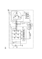
- FIG. 1 is an overall configuration diagram of a motor drive system including a motor control device according to an embodiment of the present invention.
- the motor drive system 100 includes a motor control device 1, a motor 2, an inverter 3, a rotation angle detector 41, and a high-pressure battery 5.
- the motor control device 1 generates a gate signal for controlling the drive of the motor 2 based on the torque command ⁇ * according to the target torque requested from the vehicle to the motor 2, and outputs the gate signal to the inverter 3. The details of the motor control device 1 will be described later.
- the inverter 3 has an inverter circuit 31, a PWM signal drive circuit 32, and a smoothing capacitor 33.
- the PWM signal drive circuit 32 generates a PWM signal for controlling each switching element of the inverter circuit 31 based on the gate signal input from the motor control device 1, and outputs the PWM signal to the inverter circuit 31.
- the inverter circuit 31 has switching elements corresponding to the upper arm and the lower arm of the U phase, the V phase, and the W phase, respectively. By controlling each of these switching elements according to the PWM signal input from the PWM signal drive circuit 32, the DC power supplied from the high-voltage battery 5 is converted into AC power and output to the motor 2.
- the smoothing capacitor 33 smoothes the DC power supplied from the high voltage battery 5 to the inverter circuit 31.
- the motor 2 is a three-phase alternating current synchronous motor that is rotationally driven by a three-phase alternating current output from the inverter 3, and has a stator (stator) and a rotor (rotor).
- the three-phase AC currents iu, iv, and iwa are conducted in the motor 2
- the three-phase AC currents iu, iv, and iwa are conducted in the motor 2.
- a magnetic flux corresponding to the alternating currents iu, iv, and iwa is generated.
- a magnetic pole position sensor 4 for measuring the magnetic pole position of the rotor is attached to the motor 2.
- the rotation angle detector 41 detects the rotation angle ⁇ by calculating the rotation angle ⁇ of the motor 2 according to the magnetic pole position from the input signal of the magnetic pole position sensor 4.
- the detection value of the rotation angle ⁇ by the rotation angle detector 41 is input to the motor control device 1, and the phase control of the AC power performed by the motor control device 1 generating a gate signal in accordance with the phase of the induced voltage of the motor 2. Used in.
- a resolver composed of an iron core and a winding is more suitable for the magnetic pole position sensor 4, but there is no problem even if it is a magnetoresistive element such as a GMR sensor or a sensor using a Hall element. Any sensor can be used as the magnetic pole position sensor 4 as long as the magnetic pole position of the rotor can be measured.
- a current sensor 7 is arranged between the inverter 3 and the motor 2.
- the current sensor 7 detects three-phase alternating currents iu, iv, and iv (U-phase alternating current iu, V-phase alternating current iv, and W-phase alternating current iwa) that energize and drive the motor 2 to rotate.
- the current sensor 7 is configured by using, for example, a Hall current sensor or the like.
- the detection results of the three-phase alternating currents iu, iv, and iwa by the current sensor 7 are input to the motor control device 1 and used for generating the gate signal performed by the motor control device 1.
- the AC current of the remaining one phase is the AC current of two current sensors 7.
- the sum of the three-phase alternating currents iu, iv, and iw may be calculated from zero.
- the pulsed direct current flowing from the high voltage battery 5 into the inverter 3 is detected by a shunt resistance or the like inserted between the smoothing capacitor 33 and the inverter 3, and this direct current and the inverter 3 are applied to the motor 2.
- the three-phase AC currents iu, iv, and iwa may be obtained based on the three-phase AC voltages Vu, Vv, and Vw.
- FIG. 2 is a block diagram showing a functional configuration of the motor control device 1 according to the embodiment of the present invention.
- the motor control device 1 includes a current command generation unit 11, a speed calculation unit 12, a rotation angle correction unit 13, a three-phase / dq current conversion unit 14, a current control unit 15, and a dq / three-phase voltage conversion unit 16.
- Each functional block of the gate signal generation unit 17 is provided.
- the motor control device 1 is configured by, for example, a microcomputer, and these functional blocks can be realized by executing a predetermined program in the microcomputer. Alternatively, a part or all of these functional blocks may be realized by using a hardware circuit such as a logic IC or FPGA.
- the current command generation unit 11 calculates the d-axis current command id * and the q-axis current command iq * based on the input torque command ⁇ * and the power supply voltage VB of the high-voltage battery 5.
- the d-axis current command id * and the q-axis current command iq * corresponding to the torque command ⁇ * are obtained by using a preset current command map, a mathematical formula, or the like.
- the speed calculation unit 12 calculates the motor rotation speed ⁇ r, which represents the rotation speed (rotation speed) of the motor 2, from the time change of the rotation angle ⁇ .
- the motor rotation speed ⁇ r may be a value represented by either an angular velocity (rad / s) or a rotation speed (rpm). Further, these values may be converted from each other and used.
- the rotation angle correction unit 13 detects the rotation angle ⁇ obtained by the rotation angle detector 41 based on the three-phase alternating currents iu, iv, and iwa measured by the current sensor 7 when the motor 2 is in the three-phase short-circuit state. The value is corrected, and the corrected rotation angle ⁇ c is output. The details of the rotation angle ⁇ correction method by the rotation angle correction unit 13 will be described later.
- the three-phase / dq current conversion unit 14 performs dq conversion based on the rotation angle ⁇ c corrected by the rotation angle correction unit 13 for the three-phase AC currents iu, iv, and iw detected by the current sensor 7, and the d-axis. Calculate the current value id and the q-axis current value iq.
- the current control unit 15 has the d-axis current command id * and q-axis current command iq * output from the current command generation unit 11, and the d-axis current value id and q-axis output from the three-phase / dq current conversion unit 14. Based on the deviation from the current value iq, the d-axis voltage command Vd * and the q-axis voltage command Vq * corresponding to the torque command ⁇ * are calculated so that these values match.
- the d-axis voltage command Vd *, the q-axis current command iq *, and the q-axis current value iq according to the deviation between the d-axis current command id * and the d-axis current value id are used.
- the q-axis voltage command Vq * according to the deviation is obtained.
- the dq / three-phase voltage conversion unit 16 has three phases based on the rotation angle ⁇ c corrected by the rotation angle correction unit 13 with respect to the d-axis voltage command Vd * and the q-axis voltage command Vq * calculated by the current control unit 15.
- the conversion is performed, and the three-phase voltage commands Vu *, Vv *, and Vw * (U-phase voltage command value Vu *, V-phase voltage command value Vv *, and W-phase voltage command value Vw *) are calculated.
- the three-phase voltage commands Vu *, Vv *, and Vw * corresponding to the torque command ⁇ * are generated.
- the gate signal generation unit 17 pulse-width-modulates the three-phase voltage commands Vu *, Vv *, and Vw * output from the dq / three-phase voltage conversion unit 16 to generate a gate signal for controlling the operation of the inverter 3. Generate. Specifically, based on the comparison result between the three-phase voltage commands Vu *, Vv *, Vw * output from the dq / three-phase voltage conversion unit 16 and the predetermined carrier signal, the U-phase, V-phase, and W-phase Generates a pulsed voltage for each phase. Then, based on the generated pulsed voltage, a gate signal for the switching element of each phase of the inverter 3 is generated.
- the gate signals Gup, Gbp, and Gwp of the upper arm of each phase are logically inverted to generate the gate signals Gun, Gvn, and Gwn of the lower arm.
- the gate signal generated by the gate signal generation unit 17 is output from the motor control device 1 to the PWM signal drive circuit 32 of the inverter 3, and is converted into a PWM signal by the PWM signal drive circuit 32.
- each switching element of the inverter circuit 31 is controlled on / off, and the output voltage of the inverter 3 is adjusted.
- the magnetic pole position sensor 4 attached to and used by the motor 2 may deviate from its original position due to work accuracy at the time of attachment, vibration generated during use of the motor 2, and the like. If the mounting position of the magnetic pole position sensor 4 is deviated, an error occurs in the measurement result of the magnetic pole position by the magnetic pole position sensor 4, so that the detection value of the rotation angle ⁇ output from the rotation angle detector 41 includes an error. Such an error in the rotation angle ⁇ may cause a decrease in the electricity cost of the motor 2 and an acceleration failure.
- the motor 2 is based on the three-phase alternating currents iu, iv, and iwa measured by the current sensor 7 when the motor 2 is in the three-phase short-circuit state in the rotation angle correction unit 13. Corrects the detection value of the rotation angle ⁇ output from the rotation angle detector 41 during driving. As a result, the motor 2 can be controlled by using the corrected rotation angle ⁇ c that suppresses the error of the rotation angle ⁇ due to the deviation of the mounting position of the magnetic pole position sensor 4.
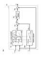
- FIG. 3 is a block diagram of the rotation angle correction unit 13 according to the first embodiment of the present invention.
- the rotation angle correction unit 13 includes each functional block of a current peak rotation angle acquisition unit 310, a reference rotation angle acquisition unit 320, a difference calculation unit 330, an angle offset storage unit 340, and a subtraction unit 350.
- the current peak rotation angle acquisition unit 310 takes any one of the three-phase AC currents iu, iv, and iw measured by the current sensor 7 when the motor 2 has a three-phase short circuit as the target phase, and the current value of the target phase.
- the detected value of the rotation angle ⁇ at the peak time of is acquired as the rotation angle ⁇ p at the time of the current peak.
- the U-phase AC current iu is the target phase
- the motor 2 is in a three-phase short-circuited state
- the U-phase AC current iu becomes the maximum peak or the minimum peak in the current peak rotation angle acquisition unit 310. Detects the timing.
- the rotation angle ⁇ p at the time of the current peak can be acquired.
- the three-phase short-circuit state is a state in which all three-phase switching elements are turned on in one of the upper arm or the lower arm and all three-phase switching elements are turned off in the other.
- the traveling energy of the vehicle rotates the rotor of the motor 2 when the inverter 3 is stopped, thereby inducing the motor 2.
- the current peak rotation angle acquisition unit 310 can detect the timing at which the U-phase AC current iu reaches the maximum peak or the minimum peak, for example, by one of the following two methods.
- the current peak rotation angle acquisition unit 310 acquires the measured value of the U-phase AC current iu output from the current sensor 7 at each predetermined sampling cycle. Then, the magnitude relationship between each acquired measured value and the previous measured value is compared, and the measured value when the magnitude relationship is reversed is acquired as the maximum current value or the minimum current value. Specifically, when the nth measured value of iu is expressed as iu_n and the previous (n-1) th measured value of iu is expressed as iu_n-1, these magnitude relations are expressed as iu_n-1 ⁇ . The measured value iu_n when changing from iu_n to iu_n-1> iu_n is acquired as the maximum current value iu_max. Alternatively, the measured value iu_n when these magnitude relations change from iu_n-1> iu_n to iu_n-1 ⁇ iu_n is acquired as the minimum current value iu_min.
- the current peak rotation angle acquisition unit 310 repeats this process a plurality of times. As a result, a plurality of maximum current values iu_max or minimum current values iu_min are acquired.
- the current peak rotation angle acquisition unit 310 obtains the median value of these. As a result, the median value iu_max (med) of the maximum current value or the median value iu_min (med) of the minimum current value can be obtained.
- the current peak rotation angle acquisition unit 310 sets the median value iu_max (med) of the maximum current value or the median value iu_min (med) of the minimum current value obtained as described above to the maximum peak of the U-phase AC current iu. Set as the minimum peak. Then, the detected value of the rotation angle ⁇ when these current values are measured is acquired as the rotation angle ⁇ p at the time of the current peak.
- the current peak rotation angle acquisition unit 310 acquires the measured value of the U-phase AC current iu output from the current sensor 7 at each predetermined sampling cycle. Then, the magnitude relationship between each acquired measured value and the previous measured value is compared, and the measured value when the magnitude relationship is reversed is acquired as the maximum current value or the minimum current value. Specifically, the maximum current value iu_max or the minimum current value iu_min is acquired by the same method as the first method described above.
- the current peak rotation angle acquisition unit 310 obtains the detected values of the rotation angle ⁇ when these current values are measured, respectively. get. By repeating this process a plurality of times, a plurality of combinations of the maximum current value iu_max or the minimum current value iu_min and the detected value of the rotation angle ⁇ are acquired.
- the rotation angle acquisition unit 310 at the time of the current peak can acquire the maximum peak of the U-phase AC current iu based on these combinations.
- the least squares method can be used to estimate the rotation angle ⁇ .
- the maximum current value iu_max or the minimum current value iu_min corresponds to the vertical axis and the rotation angle ⁇ corresponds to the horizontal axis, and each combination of these is plotted on a two-dimensional graph for each plot point.
- a straight line showing the relationship between the maximum current value iu_max or the minimum current value iu_min and the rotation angle ⁇ is obtained on a two-dimensional graph. Then, by calculating the average value of the maximum current value iu_max or the minimum current value iu_min and obtaining the rotation angle ⁇ corresponding to this average value on the above straight line, the U-phase AC current iu is at the maximum peak time or the minimum peak time. Estimate the rotation angle ⁇ in. The rotation angle ⁇ estimated in this way is acquired as the rotation angle ⁇ p at the time of the current peak.
- the current peak rotation angle ⁇ p may be acquired by a method other than the first method and the second method described above. Further, the current peak rotation angle ⁇ p may be acquired for a target phase other than the U-phase AC current iu, that is, the V-phase AC current iv or the W-phase AC current iwa.
- the detection value of the rotation angle ⁇ at the peak of the current value of the target phase is one of the three-phase AC currents iu, iv, and iw measured by the current sensor 7 when the three-phase short circuit of the motor 2 is short-circuited.
- the reference rotation angle acquisition unit 320 sets one of the three-phase AC currents iu, iv, and iw, which is the same as the rotation angle acquisition unit 310 at the time of the current peak, as the target phase, and the peak of the predetermined current waveform of the target phase.
- the rotation angle ⁇ at time is acquired as the reference rotation angle ⁇ .
- the U-phase AC current iu is the target phase
- the relationship between the U-phase AC current iu and the detected value of the rotation angle ⁇ when the magnetic pole position sensor 4 is attached to the original position is tested. Obtain in advance by simulation etc.
- the detected value of the rotation angle ⁇ at the timing when the U-phase AC current iu becomes the maximum peak or the minimum peak is acquired in advance and stored in the reference rotation angle acquisition unit 320.
- the reference rotation angle ⁇ can be acquired by the reference rotation angle acquisition unit 320.
- the reference rotation angle ⁇ may be acquired by a method other than the method described above. Further, when a target phase other than the U-phase AC current iu, that is, the V-phase AC current iv or the W-phase AC current iwa, the reference rotation angle acquisition unit 320 acquires the reference rotation angle ⁇ with respect to these target phases. Just do it. If the rotation angle ⁇ at the peak of the current waveform of the target phase when the magnetic pole position sensor 4 is attached to the original position can be acquired as the reference rotation angle ⁇ , the reference rotation angle ⁇ can be acquired by any method. It is possible to do.
- the difference calculation unit 330 calculates the difference between the current peak rotation angle ⁇ p acquired by the current peak rotation angle acquisition unit 310 and the reference rotation angle ⁇ acquired by the reference rotation angle acquisition unit 320.
- the angle offset storage unit 340 stores the difference between the current peak rotation angle ⁇ p and the reference rotation angle ⁇ calculated by the difference calculation unit 330 as the angle offset ⁇ offset.
- This angle offset ⁇ offset corresponds to an error in the detection value of the rotation angle ⁇ due to the displacement of the mounting position of the magnetic pole position sensor 4.
- ⁇ offset ⁇ 10 ° is set.
- the subtraction unit 350 subtracts the angle offset ⁇ offset stored in the angle offset storage unit 340 from the detection value of the rotation angle ⁇ output from the rotation angle detector 41 when the motor 2 is driven to rotate. As a result, the detection value of the rotation angle ⁇ is corrected so that the error due to the deviation of the mounting position of the magnetic pole position sensor 4 is suppressed.
- the subtraction result by the subtraction unit 350 is output from the rotation angle correction unit 13 to the three-phase / dq current conversion unit 14 and the dq / three-phase voltage conversion unit 16 in FIG. 2 as the corrected rotation angle ⁇ c.
- the motor 2 is controlled by the motor control device 1 using the corrected rotation angle ⁇ c.
- the current detection error of the d-axis current value id and the q-axis current value iq will be described.
- the d-axis current value id and the q-axis current value iq are calculated by the dq conversion represented by the following equation (1).
- the second term on the right side of the equation (3) represents the current detection error of the d-axis current value id and the q-axis current value iq.
- the current peak rotation angle acquisition unit 310 of the rotation angle correction unit 13 sets the detected value of the rotation angle ⁇ at the peak of the current value of the target phase to the current. Obtained as the peak rotation angle ⁇ p.
- This current peak rotation angle ⁇ p is not affected by the error even if the measured values of the three-phase AC currents iu, iv, and iwa include an error. The reason will be explained below.
- the current waveform 312 including the vertical deviation due to the offset error and the amplitude deviation due to the gain error is measured by the current sensor 7 with respect to the original U-phase current waveform 311. think of. Even in such a case, the peak position of the original current waveform 311 and the peak position of the current waveform 312 including an error are equal to each other. Therefore, the current peak rotation angle ⁇ p acquired from the current waveform 312 coincides with the peak rotation angle ⁇ in the original current waveform 311 without being affected by the measurement error by the current sensor 7.
- the current peak rotation angle acquisition unit 310 of the rotation angle correction unit 13 causes a current corresponding to the mounting position deviation of the magnetic pole position sensor 4.
- the peak rotation angle ⁇ p can be accurately obtained.
- the motor control device 1 of the present embodiment it is possible to acquire the current peak rotation angle ⁇ p according to the mounting position deviation of the magnetic pole position sensor 4, regardless of the measurement error of the current sensor 7. Therefore, as compared with the conventional method for correcting the rotation angle ⁇ , the angle offset ⁇ offset can be accurately obtained without being affected by the measurement error of the current sensor 7.
- the motor control device 1 measures the magnetic pole position of the motor 2 driven by the three-phase AC currents iu, iv, and iwa and to which the magnetic pole position sensor 4 for measuring the magnetic pole position of the rotor is attached. Control is performed using the detected value of the rotation angle ⁇ of the motor 2 based on the result.
- the motor control device 1 uses the rotation angle correction unit 13 to set any one of the three-phase alternating currents iu, iv, and iw at the time of the three-phase short circuit of the motor 2 as the target phase, and at the peak of the current value of the target phase.
- the current peak rotation angle ⁇ p which represents the detected value of the rotation angle ⁇
- the reference rotation angle ⁇ which represents the rotation angle ⁇ at the peak of the predetermined current waveform of the target phase
- the rotation angle correction unit 13 in the motor control device 1 includes a current peak rotation angle acquisition unit 310 that acquires a current peak rotation angle ⁇ p, a reference rotation angle acquisition unit 320 that acquires a reference rotation angle ⁇ , and a current.
- the difference calculation unit 330 for calculating the difference between the current peak rotation angle ⁇ p acquired by the peak rotation angle acquisition unit 310 and the reference rotation angle ⁇ acquired by the reference rotation angle acquisition unit 320, and the difference calculation unit 330. It is provided with an angle offset storage unit 340 that stores the calculated difference as an angle offset ⁇ offset.
- the rotation angle correction unit 13 uses the angle offset ⁇ offset stored by the angle offset storage unit 340 to obtain a detection value of the rotation angle ⁇ based on the measurement result of the magnetic pole position measured by the magnetic pole position sensor 4 while driving the motor 2. to correct. Since this is done, the angle offset ⁇ offset can be accurately obtained and the detected value of the rotation angle ⁇ can be corrected without being affected by the measurement error of the current sensor 7.
- the current peak rotation angle acquisition unit 310 obtains the maximum current value (for example, iu_max) or the minimum current value (for example, iu_min) when the current value of the target phase is measured in a predetermined sampling cycle.
- the detection value of the rotation angle ⁇ at the time when a plurality of acquisitions are obtained and the median value (for example, iu_max (med) or iu_min (med)) of the plurality of maximum current values or minimum current values is measured is the rotation angle ⁇ p at the time of current peak. Can be obtained as. By doing so, the rotation angle ⁇ p at the time of the current peak can be easily and accurately obtained.
- the current peak rotation angle acquisition unit 310 sets the maximum current value (for example, iu_max) or the minimum current value (for example, iu_min) when the current value of the target phase is measured in a predetermined sampling cycle.
- the current peak is obtained by acquiring a plurality of combinations with the detected values of the rotation angle ⁇ and estimating the rotation angle ⁇ at the peak of the current value of the target phase based on the plurality of combinations, for example, using the minimum square method. It is also possible to acquire the hour rotation angle ⁇ p. By doing so, the rotation angle ⁇ p at the time of the current peak can be acquired more accurately.
- the motor control device 1 controls the motor 2 by using the corrected rotation angle ⁇ c obtained by correcting the detected value of the rotation angle ⁇ by the rotation angle correction unit 13. Since this is done, it is possible to suppress the influence of the current detection error of the current sensor 7, accurately correct the error of the rotation angle ⁇ due to the deviation of the mounting position of the magnetic pole position sensor 4, and realize appropriate control of the motor 2. can.
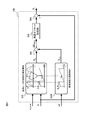
- FIG. 4 is a block diagram of the rotation angle correction unit 13A according to the second embodiment of the present invention.
- the reference rotation angle acquisition unit 320 is replaced with the reference rotation angle acquisition unit 320A as compared with the rotation angle correction unit 13 of FIG. 3 described in the first embodiment.
- the points are different.
- the configuration of the motor drive system and the functional configuration of the motor control device in this embodiment are the same as those in FIGS. 1 and 2 described in the first embodiment.
- the portion of the rotation angle correction unit 13A other than the reference rotation angle acquisition unit 320A is the same as the rotation angle correction unit 13 in FIG. Therefore, in the following, the description of the portion other than the reference rotation angle acquisition unit 320A of the motor control device according to the second embodiment of the present invention will be omitted.
- the reference rotation angle acquisition unit 320A acquires the temperature Tr of the rotor of the motor 2.
- the rotor temperature Tr can be obtained from, for example, a temperature sensor attached to the rotor of the motor 2.
- the rotor temperature Tr may be estimated based on a temperature other than the rotor, for example, the temperature of the refrigerant used for cooling the motor 2, the atmospheric temperature, or the like.
- the reference rotation angle acquisition unit 320A sets the value of the reference rotation angle ⁇ tp according to the rotor temperature Tr based on the acquired rotor temperature Tr value, and outputs the value to the difference calculation unit 330.
- the relationship between the rotor temperature Tr and the reference rotation angle ⁇ tmp can be expressed by a functional formula based on the laws of physics, and the reference rotation angle ⁇ tp according to the rotor temperature Tr can be calculated online using this functional formula. ..
- map information representing various combinations of the rotor temperature Tr and the reference rotation angle ⁇ tp is created in advance by experiments, simulations, etc., and using this map information, the reference rotation angle ⁇ mp according to the rotor temperature Tr is used. The value of may be obtained offline. Thereby, the value of the reference rotation angle ⁇ tp can be changed based on the rotor temperature Tr.
- Vd - ⁇ r ⁇ Ld ⁇ iq + R ⁇ id ⁇ ⁇ ⁇ (4)
- Vq ⁇ r ⁇ ⁇ + R ⁇ iq + ⁇ r ⁇ Ld ⁇ id ⁇ ⁇ ⁇ (5)
- ⁇ atan (-id / iq) ⁇ ⁇ ⁇ (6)
- the reference rotation angle ⁇ depends on the motor rotation speed ⁇ r, the q-axis inductance Lq, and the winding resistance R.
- the q-axis inductance Lq and the winding resistance R fluctuate according to the temperature of each coil, that is, the rotor temperature Tr. Therefore, if the reference rotation angle ⁇ is kept constant regardless of the rotor temperature Tr as in the first embodiment, the three-phase AC currents iu, iv, iwa and the reference rotation angle ⁇ depend on the value of the rotor temperature Tr.
- the rotation angle correction unit 13 may not be able to correctly acquire the angle offset ⁇ offset. As a result, the torque accuracy is lowered in the control of the motor 2, which may cause disadvantages such as deterioration of electricity cost and poor acceleration.
- the reference rotation angle ⁇ tpm is changed based on the rotor temperature Tr in the reference rotation angle acquisition unit 320A as described above.
- the rotation angle correction unit 13A calculates the angle offset ⁇ offset by using this reference rotation angle ⁇ tp instead of the constant reference rotation angle ⁇ . This makes it possible to accurately acquire the angle offset ⁇ offset even if the rotor temperature Tr fluctuates.
- FIG. 5 is a diagram illustrating a specific example of a method for setting a reference rotation angle ⁇ tpm in the reference rotation angle acquisition unit 320A according to the second embodiment of the present invention.
- the vector diagram 400 shown in (a) represents the reference rotation angle ⁇ tpm at low temperature
- the vector diagram 410 shown in FIG. 5 (b) represents the reference rotation angle ⁇ mpmp at high temperature.
- the current vector corresponding to the preset reference rotation angle ⁇ is represented by I1
- the current vector corresponding to the reference rotation angle ⁇ tp according to the temperature is represented by I1 mp.
- the angle difference of is expressed by ⁇ tpm.
- the rotation is as described above.
- the values of the q-axis inductance Lq and the winding resistance R vary depending on the child temperature Tr.
- the d-axis current id and the q-axis current iq change as id_tpm and iq_tmp in the vector diagrams 400 and 410, respectively.
- ⁇ mp ⁇ + ⁇ mp ⁇ ⁇ ⁇ (8)
- the reference rotation angle acquisition unit 320A changes the reference rotation angle ⁇ tmp based on the rotor temperature Tr representing the temperature of the rotor. Since this is done, the angle offset ⁇ offset can be accurately acquired even when the motor 2 has a high temperature or a low temperature.
- FIG. 6 is a block diagram of the rotation angle correction unit 13B according to the third embodiment of the present invention.
- the reference rotation angle acquisition unit 320 is replaced with the reference rotation angle acquisition unit 320B as compared with the rotation angle correction unit 13 of FIG. 3 described in the first embodiment.
- the points are different.
- the configuration of the motor drive system and the functional configuration of the motor control device in this embodiment are the same as those in FIGS. 1 and 2 described in the first embodiment.
- the portion of the rotation angle correction unit 13B other than the reference rotation angle acquisition unit 320B is the same as the rotation angle correction unit 13 in FIG. Therefore, in the following, the description of the portion other than the reference rotation angle acquisition unit 320B of the motor control device according to the third embodiment of the present invention will be omitted.
- the reference rotation angle acquisition unit 320B acquires the motor rotation speed ⁇ r representing the rotation speed of the motor 2 from the speed calculation unit 12. Then, based on the acquired value of the motor rotation speed ⁇ r, the value of the reference rotation angle ⁇ spd corresponding to the motor rotation speed ⁇ r is set and output to the difference calculation unit 330.
- the relationship between the motor rotation speed ⁇ r and the reference rotation angle ⁇ spd can be expressed by a functional formula based on the laws of physics, and the reference rotation angle ⁇ spd corresponding to the motor rotation speed ⁇ r can be calculated online using this functional formula. ..
- map information representing various combinations of the motor rotation speed ⁇ r and the reference rotation angle ⁇ spd is created in advance by experiments, simulations, etc., and using this map information, the reference rotation angle ⁇ spd according to the motor rotation speed ⁇ r is used. The value of may be obtained offline. Thereby, the reference rotation angle ⁇ spd can be changed based on the rotation speed of the motor 2.
- the reference rotation angle ⁇ depends on the motor rotation speed ⁇ r, the q-axis inductance Lq, and the winding resistance R.
- the reference rotation angle ⁇ is kept constant regardless of the motor rotation speed ⁇ r as in the first embodiment, the three-phase AC currents iu, iv, iwa and the reference rotation angle ⁇ depend on the value of the motor rotation speed ⁇ r.
- the rotation angle correction unit 13 may not be able to correctly acquire the angle offset ⁇ offset. As a result, the torque accuracy is lowered in the control of the motor 2, which may cause disadvantages such as deterioration of electricity cost and poor acceleration.
- the reference rotation angle ⁇ spd is changed in the reference rotation angle acquisition unit 320B based on the motor rotation speed ⁇ r as described above.
- the rotation angle correction unit 13B calculates the angle offset ⁇ offset by using this reference rotation angle ⁇ spd instead of the constant reference rotation angle ⁇ . This makes it possible to accurately acquire the angle offset ⁇ offset even when the motor 2 rotates at a low speed.
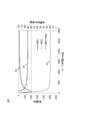
- FIG. 7 is a diagram illustrating a specific example of a method of setting the reference rotation angle ⁇ spd in the reference rotation angle acquisition unit 320B according to the third embodiment of the present invention.
- the relationships between the motor rotation speed ⁇ r, the d-axis current id, the q-axis current iq, and the reference rotation angle ⁇ spd during the three-phase short circuit of the motor 2 are shown in curves 500, 510, and 520, respectively.
- the reference rotation angle acquisition unit 320B changes the reference rotation angle ⁇ spd based on the motor rotation speed ⁇ r representing the rotation speed of the rotor. Since this is done, the angle offset ⁇ offset can be accurately acquired even when the motor 2 rotates at a low speed.
Landscapes
- Engineering & Computer Science (AREA)
- Power Engineering (AREA)
- Control Of Ac Motors In General (AREA)
- Control Of Motors That Do Not Use Commutators (AREA)
Abstract
モータ制御装置は、三相交流電流によって駆動され、ロータの磁極位置を測定する磁極位置センサが取り付けられたモータを、前記磁極位置センサによる前記磁極位置の測定結果に基づく前記モータの回転角度の検出値を用いて制御するものであって、前記モータの三相短絡時の前記三相交流電流のうちいずれか一相を対象相として、前記対象相の電流値のピーク時における前記回転角度の検出値を表す電流ピーク時回転角度と、前記対象相の所定の電流波形のピーク時における前記回転角度を表す基準回転角度とを比較し、その比較結果に基づいて、前記回転角度の検出値を補正する。
Description
本発明は、モータ制御装置およびモータ制御方法に関する。
三相交流モータの制御を行うためにロータの磁極位置を測定する磁極位置センサが広く利用されている。磁極位置センサの取付位置が本来の位置からずれている場合、磁極位置センサによる磁極位置の測定結果から求められるモータの回転角度に誤差が生じてしまい、モータの電費低下や加速不良などを引き起こすおそれがある。そのため、磁極位置センサの取付位置のずれに応じた角度オフセットを予め求めておき、この角度オフセットを用いて回転角度の誤差を補正することが一般的に行われている。
角度オフセットを用いた回転角度の補正方法として、下記特許文献1の技術が知られている。特許文献1には、モータの回転角度に位相誤差が発生していない場合の相電流を相電流理論値として算出しておき、モータ端を短絡させた状態で相電流検出部が検出した相電流と相電流理論値との差に基づいて位相誤差補正値を算出し、この位相誤差補正値を用いて回転角度に位相補正を行うモータ制御装置が開示されている。
三相交流モータに流れる相電流は、一般的に電流センサを用いて検出されるが、その検出値には電流センサの特性に起因する誤差(オフセット誤差、ゲイン誤差)が含まれている。特許文献1のモータ制御装置では、こうした相電流の検出誤差の影響により、位相誤差補正値の精度が低下する。したがって、三相交流モータの回転角度の計算精度に関して改善の余地がある。
本発明によるモータ制御装置は、三相交流電流によって駆動され、ロータの磁極位置を測定する磁極位置センサが取り付けられたモータを、前記磁極位置センサによる前記磁極位置の測定結果に基づく前記モータの回転角度の検出値を用いて制御するものであって、前記モータの三相短絡時の前記三相交流電流のうちいずれか一相を対象相として、前記対象相の電流値のピーク時における前記回転角度の検出値を表す電流ピーク時回転角度と、前記対象相の所定の電流波形のピーク時における前記回転角度を表す基準回転角度とを比較し、その比較結果に基づいて、前記回転角度の検出値を補正する。
本発明によるモータ制御方法は、三相交流電流によって駆動され、ロータの回転角度を測定する磁極位置センサが取り付けられたモータを、前記磁極位置センサによる前記磁極位置の測定結果に基づく前記モータの回転角度の検出値を用いて制御する方法であって、前記モータの三相短絡時の前記三相交流電流のうちいずれか一相を対象相として、前記対象相の電流値のピーク時における前記回転角度の検出値を表す電流ピーク時回転角度と、所定の電流波形のピーク時における前記回転角度を表す基準回転角度とを比較し、前記電流ピーク時回転角度と前記基準回転角度との比較結果に基づいて、前記回転角度の検出値を補正し、補正後の前記回転角度の検出値を用いて、前記モータの制御を行う。
本発明によるモータ制御方法は、三相交流電流によって駆動され、ロータの回転角度を測定する磁極位置センサが取り付けられたモータを、前記磁極位置センサによる前記磁極位置の測定結果に基づく前記モータの回転角度の検出値を用いて制御する方法であって、前記モータの三相短絡時の前記三相交流電流のうちいずれか一相を対象相として、前記対象相の電流値のピーク時における前記回転角度の検出値を表す電流ピーク時回転角度と、所定の電流波形のピーク時における前記回転角度を表す基準回転角度とを比較し、前記電流ピーク時回転角度と前記基準回転角度との比較結果に基づいて、前記回転角度の検出値を補正し、補正後の前記回転角度の検出値を用いて、前記モータの制御を行う。
本発明によれば、三相交流モータの回転角度を精度良く求めることができる。
(第1の実施形態)
以下、本発明の第1の実施形態について図面を用いて説明する。
以下、本発明の第1の実施形態について図面を用いて説明する。
図1は、本発明の一実施形態に係るモータ制御装置を備えたモータ駆動システムの全体構成図である。図1において、モータ駆動システム100は、モータ制御装置1、モータ2、インバータ3、回転角度検出器41、高圧バッテリ5を備える。
モータ制御装置1は、車両からモータ2に対して要求される目標トルクに応じたトルク指令τ*に基づいて、モータ2の駆動を制御するためのゲート信号を生成し、インバータ3に出力する。なお、モータ制御装置1の詳細については後で説明する。
インバータ3は、インバータ回路31、PWM信号駆動回路32および平滑キャパシタ33を有する。PWM信号駆動回路32は、モータ制御装置1から入力されるゲート信号に基づいて、インバータ回路31が有する各スイッチング素子を制御するためのPWM信号を生成し、インバータ回路31に出力する。インバータ回路31は、U相、V相、W相の上アームおよび下アームにそれぞれ対応するスイッチング素子を有している。PWM信号駆動回路32から入力されたPWM信号に従ってこれらのスイッチング素子がそれぞれ制御されることで、高圧バッテリ5から供給される直流電力が交流電力に変換され、モータ2に出力される。平滑キャパシタ33は、高圧バッテリ5からインバータ回路31に供給される直流電力を平滑化する。
モータ2は、インバータ3から出力される三相交流電流によって回転駆動される三相交流同期モータであり、固定子(ステータ)および回転子(ロータ)を有する。インバータ3から入力された交流電力が固定子に設けられた三相コイルLu、Lv、Lwに印加されると、モータ2において三相交流電流iu、iv、iwが導通し、各コイルに三相交流電流iu、iv、iwに応じた磁束が発生する。この各コイルの磁束と、回転子に配置された永久磁石の磁石磁束との間で吸引力・反発力が発生することで、回転子にトルクが発生し、回転子が回転駆動される。
モータ2には、回転子の磁極位置を測定する磁極位置センサ4が取り付けられている。回転角度検出器41は、磁極位置センサ4の入力信号から磁極位置に応じたモータ2の回転角度θを演算することで、回転角度θを検出する。回転角度検出器41による回転角度θの検出値はモータ制御装置1に入力され、モータ制御装置1がモータ2の誘起電圧の位相に合わせてゲート信号を生成することで行われる交流電力の位相制御において利用される。
ここで、磁極位置センサ4には、鉄心と巻線とから構成されるレゾルバがより好適であるが、GMRセンサなどの磁気抵抗素子や、ホール素子を用いたセンサであっても問題ない。回転子の磁極位置を測定することができれば、任意のセンサを磁極位置センサ4として用いることができる。
インバータ3とモータ2の間には、電流センサ7が配置されている。電流センサ7は、モータ2を通電して回転駆動させる三相交流電流iu、iv、iw(U相交流電流iu、V相交流電流ivおよびW相交流電流iw)を検出する。電流センサ7は、例えばホール電流センサ等を用いて構成される。電流センサ7による三相交流電流iu、iv、iwの検出結果はモータ制御装置1に入力され、モータ制御装置1が行うゲート信号の生成に利用される。なお、図1ではU相、V相、W相にそれぞれ対応して3つの電流センサ7が設置されている例を示しているが、電流センサ7を2つとし、残る1相の交流電流は、三相交流電流iu、iv、iwの和が零であることから算出してもよい。また、高圧バッテリ5からインバータ3に流入するパルス状の直流電流を、平滑キャパシタ33とインバータ3の間に挿入されたシャント抵抗等により検出し、この直流電流とインバータ3からモータ2に印加される三相交流電圧Vu、Vv、Vwに基づいて、三相交流電流iu、iv、iwを求めてもよい。
次に、モータ制御装置1の詳細について説明する。図2は、本発明の一実施形態に係るモータ制御装置1の機能構成を示すブロック図である。図2において、モータ制御装置1は、電流指令生成部11、速度算出部12、回転角度補正部13、三相/dq電流変換部14、電流制御部15、dq/三相電圧変換部16、ゲート信号生成部17の各機能ブロックを有する。モータ制御装置1は、例えばマイクロコンピュータにより構成され、マイクロコンピュータにおいて所定のプログラムを実行することにより、これらの機能ブロックを実現することができる。あるいは、これらの機能ブロックの一部または全部をロジックICやFPGA等のハードウェア回路を用いて実現してもよい。
電流指令生成部11は、入力されたトルク指令τ*と高圧バッテリ5の電源電圧VBに基づき、d軸電流指令id*およびq軸電流指令iq*を演算する。ここでは、例えば予め設定された電流指令マップや数式等を用いて、トルク指令τ*に応じたd軸電流指令id*、q軸電流指令iq*を求める。
速度算出部12は、回転角度θの時間変化から、モータ2の回転速度(回転数)を表すモータ回転速度ωrを演算する。なお、モータ回転速度ωrは、角速度(rad/s)または回転数(rpm)のいずれで表される値であってもよい。また、これらの値を相互に変換して用いてもよい。
回転角度補正部13は、モータ2が三相短絡状態のときに電流センサ7によって測定された三相交流電流iu、iv、iwに基づいて、回転角度検出器41が求めた回転角度θの検出値を補正し、補正後の回転角度θcを出力する。なお、回転角度補正部13による回転角度θの補正方法の詳細については後述する。
三相/dq電流変換部14は、電流センサ7が検出した三相交流電流iu、iv、iwに対して、回転角度補正部13による補正後の回転角度θcに基づくdq変換を行い、d軸電流値idおよびq軸電流値iqを演算する。
電流制御部15は、電流指令生成部11から出力されるd軸電流指令id*およびq軸電流指令iq*と、三相/dq電流変換部14から出力されるd軸電流値idおよびq軸電流値iqとの偏差に基づき、これらの値がそれぞれ一致するように、トルク指令τ*に応じたd軸電圧指令Vd*およびq軸電圧指令Vq*を演算する。ここでは、例えばPI制御等の制御方式により、d軸電流指令id*とd軸電流値idの偏差に応じたd軸電圧指令Vd*と、q軸電流指令iq*とq軸電流値iqの偏差に応じたq軸電圧指令Vq*とを求める。
dq/三相電圧変換部16は、電流制御部15が演算したd軸電圧指令Vd*およびq軸電圧指令Vq*に対して、回転角度補正部13による補正後の回転角度θcに基づく三相変換を行い、三相電圧指令Vu*、Vv*、Vw*(U相電圧指令値Vu*、V相電圧指令値Vv*およびW相電圧指令値Vw*)を演算する。これにより、トルク指令τ*に応じた三相電圧指令Vu*、Vv*、Vw*を生成する。
ゲート信号生成部17は、dq/三相電圧変換部16から出力される三相電圧指令Vu*、Vv*、Vw*をそれぞれパルス幅変調し、インバータ3の動作を制御するためのゲート信号を生成する。具体的には、dq/三相電圧変換部16から出力される三相電圧指令Vu*、Vv*、Vw*と所定のキャリア信号との比較結果に基づき、U相、V相、W相の各相に対してパルス状の電圧を生成する。そして、生成したパルス状の電圧に基づき、インバータ3の各相のスイッチング素子に対するゲート信号を生成する。このとき、各相の上アームのゲート信号Gup、Gvp、Gwpをそれぞれ論理反転させ、下アームのゲート信号Gun、Gvn、Gwnを生成する。ゲート信号生成部17が生成したゲート信号は、モータ制御装置1からインバータ3のPWM信号駆動回路32に出力され、PWM信号駆動回路32によってPWM信号に変換される。これにより、インバータ回路31の各スイッチング素子がオン/オフ制御され、インバータ3の出力電圧が調整される。
次に、モータ制御装置1における回転角度補正部13の動作について説明する。モータ2に取り付けられて使用される磁極位置センサ4は、取付時の作業精度やモータ2の使用中に生じる振動などに起因して、その取付位置が本来の位置からずれる場合がある。磁極位置センサ4の取付位置にずれが生じると、磁極位置センサ4による磁極位置の測定結果に誤差が生じるため、回転角度検出器41から出力される回転角度θの検出値に誤差が含まれる。このような回転角度θの誤差は、モータ2の電費低下や加速不良などを引き起こすおそれがある。そのため、本実施形態のモータ制御装置1では、回転角度補正部13において、モータ2が三相短絡状態のときに電流センサ7によって測定された三相交流電流iu、iv、iwに基づき、モータ2の駆動中に回転角度検出器41から出力される回転角度θの検出値を補正する。これにより、磁極位置センサ4の取付位置ずれによる回転角度θの誤差を抑制した補正後の回転角度θcを用いて、モータ2の制御を実施できるようにしている。
図3は、本発明の第1の実施形態に係る回転角度補正部13のブロック図である。回転角度補正部13は、電流ピーク時回転角度取得部310、基準回転角度取得部320、差分算出部330、角度オフセット記憶部340および減算部350の各機能ブロックを備えて構成される。
電流ピーク時回転角度取得部310は、モータ2の三相短絡時に電流センサ7によって測定された三相交流電流iu、iv、iwのうちいずれか一相を対象相として、その対象相の電流値のピーク時における回転角度θの検出値を、電流ピーク時回転角度θpとして取得する。具体的には、例えばU相交流電流iuを対象相とした場合、モータ2が三相短絡状態になると、電流ピーク時回転角度取得部310において、U相交流電流iuが最大ピークまたは最小ピークとなるタイミングを検出する。そして、このタイミングで回転角度検出器41から出力される回転角度θの検出値を取得することで、電流ピーク時回転角度θpを取得することができる。
なお、三相短絡状態とは周知のように、インバータ3において上アームまたは下アームの一方では三相全てのスイッチング素子をオンにし、他方では三相全てのスイッチング素子をオフにした状態のことである。例えば電気自動車やハイブリッド自動車に搭載されて当該車両の走行用モータとしてモータ2が利用される場合、インバータ3の停止時に車両の走行エネルギーがモータ2の回転子を回転させることで、モータ2の誘起電圧が上昇する。この誘起電圧がインバータ3のスイッチング素子の耐圧を超えると、スイッチング素子が破壊されるおそれがある。そのため、モータ2を三相短絡状態としてモータ2内で電流を還流させることで、スイッチング素子を保護するようにしている。
電流ピーク時回転角度取得部310は、U相交流電流iuが最大ピークまたは最小ピークとなるタイミングを、例えば以下の2つの方法のいずれかにより、検出することが可能である。
(第1の方法)
電流ピーク時回転角度取得部310は、電流センサ7から出力されるU相交流電流iuの測定値を、所定のサンプリング周期ごとに取得する。そして、取得した各測定値とその前の測定値との大小関係を比較し、大小関係が反転したときの測定値を最大電流値または最小電流値として取得する。具体的には、n回目のiuの測定値をiu_nと表し、その前の(n-1)回目のiuの測定値をiu_n-1と表した場合に、これらの大小関係がiu_n-1<iu_nからiu_n-1>iu_nへ変化したときの測定値iu_nを、最大電流値iu_maxとして取得する。または、これらの大小関係がiu_n-1>iu_nからiu_n-1<iu_nへ変化したときの測定値iu_n、を、最小電流値iu_minとして取得する。
電流ピーク時回転角度取得部310は、電流センサ7から出力されるU相交流電流iuの測定値を、所定のサンプリング周期ごとに取得する。そして、取得した各測定値とその前の測定値との大小関係を比較し、大小関係が反転したときの測定値を最大電流値または最小電流値として取得する。具体的には、n回目のiuの測定値をiu_nと表し、その前の(n-1)回目のiuの測定値をiu_n-1と表した場合に、これらの大小関係がiu_n-1<iu_nからiu_n-1>iu_nへ変化したときの測定値iu_nを、最大電流値iu_maxとして取得する。または、これらの大小関係がiu_n-1>iu_nからiu_n-1<iu_nへ変化したときの測定値iu_n、を、最小電流値iu_minとして取得する。
上記の処理により、最大電流値iu_maxまたは最小電流値iu_minを取得することができたら、電流ピーク時回転角度取得部310は、この処理を複数回繰り返して実施する。これにより、最大電流値iu_maxまたは最小電流値iu_minを複数取得する。
最大電流値iu_maxまたは最小電流値iu_minを複数取得できたら、電流ピーク時回転角度取得部310は、これらの中央値を求める。これにより、最大電流値の中央値iu_max(med)、または最小電流値の中央値iu_min(med)が求められる。
電流ピーク時回転角度取得部310は、上記のようにして求められた最大電流値の中央値iu_max(med)または最小電流値の中央値iu_min(med)を、U相交流電流iuの最大ピークまたは最小ピークとして設定する。そして、これらの電流値が測定されたときの回転角度θの検出値を、電流ピーク時回転角度θpとして取得する。
(第2の方法)
電流ピーク時回転角度取得部310は、電流センサ7から出力されるU相交流電流iuの測定値を、所定のサンプリング周期ごとに取得する。そして、取得した各測定値とその前の測定値との大小関係を比較し、大小関係が反転したときの測定値を最大電流値または最小電流値として取得する。具体的には、前述の第1の方法と同様の手法により、最大電流値iu_maxまたは最小電流値iu_minを取得する。
電流ピーク時回転角度取得部310は、電流センサ7から出力されるU相交流電流iuの測定値を、所定のサンプリング周期ごとに取得する。そして、取得した各測定値とその前の測定値との大小関係を比較し、大小関係が反転したときの測定値を最大電流値または最小電流値として取得する。具体的には、前述の第1の方法と同様の手法により、最大電流値iu_maxまたは最小電流値iu_minを取得する。
上記の処理により、最大電流値iu_maxまたは最小電流値iu_minを取得することができたら、電流ピーク時回転角度取得部310は、これらの電流値が測定されたときの回転角度θの検出値をそれぞれ取得する。この処理を複数回繰り返して実施することにより、最大電流値iu_maxまたは最小電流値iu_minと回転角度θの検出値との組み合わせを複数取得する。
最大電流値iu_maxまたは最小電流値iu_minと回転角度θの検出値との組み合わせを複数取得できたら、電流ピーク時回転角度取得部310は、これらの組み合わせに基づいて、U相交流電流iuの最大ピーク時または最小ピーク時における回転角度θを推定する。この回転角度θの推定には、例えば最小二乗法を用いることができる。具体的には、例えば最大電流値iu_maxまたは最小電流値iu_minを縦軸、回転角度θを横軸にそれぞれ対応させて、これらの各組み合わせを2次元グラフ上にプロットし、各プロット点に対して最小二乗法を適用することで、最大電流値iu_maxまたは最小電流値iu_minと回転角度θの関係を示す直線を2次元グラフ上で求める。そして、最大電流値iu_maxまたは最小電流値iu_minの平均値を算出し、この平均値に対応する回転角度θを上記の直線上で求めることにより、U相交流電流iuの最大ピーク時または最小ピーク時における回転角度θを推定する。こうして推定した回転角度θを、電流ピーク時回転角度θpとして取得する。
なお、以上説明した第1の方法、第2の方法以外の方法により、電流ピーク時回転角度θpを取得してもよい。また、U相交流電流iu以外、すなわちV相交流電流ivまたはW相交流電流iwを対象相として、電流ピーク時回転角度θpを取得してもよい。モータ2の三相短絡時に電流センサ7によって測定された三相交流電流iu、iv、iwのうちいずれか一相を対象相として、その対象相の電流値のピーク時における回転角度θの検出値を、電流ピーク時回転角度θpとして取得することができれば、任意の方法で電流ピーク時回転角度θpを取得することが可能である。
図3では、電流ピーク時回転角度取得部310により、U相交流電流iuの最大ピークに対する電流ピーク時回転角度θpとしてθp=300°、最小ピークに対する電流ピーク時回転角度θpとしてθp=120°がそれぞれ取得された場合の例を示している。
基準回転角度取得部320は、三相交流電流iu、iv、iwのうち、電流ピーク時回転角度取得部310と同一のいずれか一相を対象相として、その対象相の所定の電流波形のピーク時における回転角度θを、基準回転角度βとして取得する。ここでは、例えばU相交流電流iuを対象相とした場合、磁極位置センサ4が本来の位置に取り付けられているときのU相交流電流iuと回転角度θの検出値との関係を、実験やシミュレーション等により事前に取得する。この関係に基づき、U相交流電流iuが最大ピークまたは最小ピークとなるタイミングでの回転角度θの検出値を予め取得し、基準回転角度取得部320に記憶しておく。これにより、基準回転角度取得部320において基準回転角度βを取得することができる。
なお、以上説明した方法以外で基準回転角度βを取得してもよい。また、U相交流電流iu以外、すなわちV相交流電流ivまたはW相交流電流iwを対象相とした場合、基準回転角度取得部320は、これらの対象相に対して基準回転角度βを取得すればよい。磁極位置センサ4が本来の位置に取り付けられているときの対象相の電流波形のピーク時における回転角度θを、基準回転角度βとして取得することができれば、任意の方法で基準回転角度βを取得することが可能である。
図3では、基準回転角度取得部320により、U相交流電流iuの最大ピークに対する基準回転角度βとしてβ=310°、最小ピークに対する基準回転角度βとしてβ=130°がそれぞれ取得された場合の例を示している。
差分算出部330は、電流ピーク時回転角度取得部310により取得された電流ピーク時回転角度θpと、基準回転角度取得部320により取得された基準回転角度βとの差分を算出する。
角度オフセット記憶部340は、差分算出部330により算出された電流ピーク時回転角度θpと基準回転角度βとの差分を、角度オフセットΔβoffsetとして記憶する。この角度オフセットΔβoffsetは、磁極位置センサ4の取付位置ずれによる回転角度θの検出値の誤差に相当する。図3の例では、最大ピーク、最小ピークのいずれについてもθp-β=-10°であるため、Δβoffset=-10°が設定される。
減算部350は、モータ2の回転駆動時に回転角度検出器41から出力される回転角度θの検出値から、角度オフセット記憶部340に記憶された角度オフセットΔβoffsetを減算する。これにより、磁極位置センサ4の取付位置ずれによる誤差が抑制されるように、回転角度θの検出値を補正する。
減算部350による減算結果は、補正後の回転角度θcとして、回転角度補正部13から図2の三相/dq電流変換部14およびdq/三相電圧変換部16に出力される。これにより、補正後の回転角度θcを用いて、モータ制御装置1によるモータ2の制御が行われる。
ここで、従来の回転角度θの補正方法と比較して、本実施形態のモータ制御装置1における回転角度θの補正方法の利点を以下に説明する。
従来の回転角度θの補正方法として、モータ2の三相短絡時に電流センサ7によって検出された三相交流電流iu、iv、iwをdq変換して得られたd軸電流値idおよびq軸電流値iqに基づき、磁極位置センサ4の取付位置ずれに応じた角度を求めて角度オフセットΔβoffsetを算出する方法が知られている。しかしながら、こうした従来の角度オフセットΔβoffsetの算出方法では、電流センサ7による三相交流電流iu、iv、iwの測定値に含まれる誤差により、d軸電流値idおよびq軸電流値iqにおいて電流検出誤差が発生する。そのため、角度オフセットΔβoffsetを正確に求めることができない。
以下では、d軸電流値idとq軸電流値iqの電流検出誤差について説明する。三相/dq電流変換部14では、下記の式(1)で表されるdq変換により、d軸電流値idおよびq軸電流値iqが算出される。

ここで、三相交流電流iu、iv、iwの測定値がそれぞれ誤差αu,αv,αwを含んでいる場合、式(1)は下記の式(2)のように表される。

式(2)を展開すると、以下の式(3)が得られる。

式(3)の右辺第2項は、d軸電流値idとq軸電流値iqの電流検出誤差を表している。このように、三相交流電流iu、iv、iwの測定値に誤差が含まれている場合、d軸電流値idおよびq軸電流値iqにおいて電流検出誤差が発生するため、角度オフセットΔβoffsetを正確に求めることができなくなる。特にモータ2が高回転や高トルクとなる領域では、電流検出誤差による影響が顕著となる。その結果、例えばモータ2が車両の走行用モータである場合、乗り心地や走行性能が損なわれる可能性がある。
一方、本実施形態のモータ制御装置1では、回転角度補正部13の電流ピーク時回転角度取得部310において前述のように、対象相の電流値のピーク時における回転角度θの検出値を、電流ピーク時回転角度θpとして取得する。この電流ピーク時回転角度θpは、三相交流電流iu、iv、iwの測定値に誤差が含まれていても、その誤差の影響を受けることがない。その理由を以下に説明する。
例えば図3に示すように、本来のU相の電流波形311に対して、オフセット誤差による上下のずれと、ゲイン誤差による振幅のずれとを含む電流波形312が、電流センサ7により測定された場合を考える。このような場合でも、本来の電流波形311のピーク位置と、誤差を含む電流波形312のピーク位置とは等しい。したがって、電流波形312から取得される電流ピーク時回転角度θpは、電流センサ7による測定誤差の影響を受けることなく、本来の電流波形311におけるピーク時の回転角度θと一致する。すなわち、本実施形態のモータ制御装置1では、電流センサ7の測定誤差に関わらず、回転角度補正部13の電流ピーク時回転角度取得部310により、磁極位置センサ4の取付位置ずれに応じた電流ピーク時回転角度θpを正確に取得することができる。
以上説明したように、本実施形態のモータ制御装置1では、電流センサ7の測定誤差に関わらず、磁極位置センサ4の取付位置ずれに応じた電流ピーク時回転角度θpを取得することができる。したがって、従来の回転角度θの補正方法と比較して、電流センサ7の測定誤差による影響を受けずに、角度オフセットΔβoffsetを正確に求めることが可能となる。
以上説明した本発明の第1の実施形態によれば、以下の作用効果を奏する。
(1)モータ制御装置1は、三相交流電流iu、iv、iwによって駆動され、ロータの磁極位置を測定する磁極位置センサ4が取り付けられたモータ2を、磁極位置センサ4による磁極位置の測定結果に基づくモータ2の回転角度θの検出値を用いて制御する。モータ制御装置1は、回転角度補正部13により、モータ2の三相短絡時の三相交流電流iu、iv、iwのうちいずれか一相を対象相として、その対象相の電流値のピーク時における回転角度θの検出値を表す電流ピーク時回転角度θpと、対象相の所定の電流波形のピーク時における回転角度θを表す基準回転角度βとを比較し、その比較結果に基づいて、回転角度θの検出値を補正する。このようにしたので、三相交流モータ2の回転角度θを精度良く求めることができる。
(2)モータ制御装置1における回転角度補正部13は、電流ピーク時回転角度θpを取得する電流ピーク時回転角度取得部310と、基準回転角度βを取得する基準回転角度取得部320と、電流ピーク時回転角度取得部310により取得された電流ピーク時回転角度θpと、基準回転角度取得部320により取得された基準回転角度βとの差分を算出する差分算出部330と、差分算出部330により算出された差分を角度オフセットΔβoffsetとして記憶する角度オフセット記憶部340とを備える。回転角度補正部13は、角度オフセット記憶部340により記憶された角度オフセットΔβoffsetを用いて、モータ2の駆動中に磁極位置センサ4が測定した磁極位置の測定結果に基づく回転角度θの検出値を補正する。このようにしたので、電流センサ7の測定誤差による影響を受けずに、角度オフセットΔβoffsetを正確に求めて回転角度θの検出値を補正することができる。
(3)電流ピーク時回転角度取得部310は、第1の方法として、対象相の電流値を所定のサンプリング周期で測定したときの最大電流値(例えばiu_max)または最小電流値(例えばiu_min)を複数取得し、その複数の最大電流値または最小電流値の中央値(例えばiu_max(med)またはiu_min(med))が測定された時点での回転角度θの検出値を、電流ピーク時回転角度θpとして取得することができる。このようにすれば、電流ピーク時回転角度θpを容易かつ正確に取得することができる。
(4)電流ピーク時回転角度取得部310は、第2の方法として、対象相の電流値を所定のサンプリング周期で測定したときの最大電流値(例えばiu_max)または最小電流値(例えばiu_min)と回転角度θの検出値との組み合わせを複数取得し、その複数の組み合わせに基づいて、例えば最小二乗法を用いて、対象相の電流値のピーク時における回転角度θを推定することで、電流ピーク時回転角度θpを取得することもできる。このようにすれば、電流ピーク時回転角度θpをより一層正確に取得することができる。
(5)モータ制御装置1は、回転角度補正部13により回転角度θの検出値を補正して求められた補正後の回転角度θcを用いて、モータ2の制御を行う。このようにしたので、電流センサ7の電流検出誤差による影響を抑えて、磁極位置センサ4の取付位置ずれによる回転角度θの誤差を正確に補正し、モータ2の適切な制御を実現することができる。
(第2の実施形態)
次に、本発明の第2の実施形態について図面を用いて説明する。本実施形態では、モータ2の回転子の温度に基づいて基準回転角度を変化させる例を説明する。
次に、本発明の第2の実施形態について図面を用いて説明する。本実施形態では、モータ2の回転子の温度に基づいて基準回転角度を変化させる例を説明する。
図4は、本発明の第2の実施形態に係る回転角度補正部13Aのブロック図である。図4に示す回転角度補正部13Aは、第1の実施形態で説明した図3の回転角度補正部13と比較して、基準回転角度取得部320が基準回転角度取得部320Aに置き換えられている点が異なっている。なお、本実施形態におけるモータ駆動システムの構成やモータ制御装置の機能構成については、第1の実施形態で説明した図1、図2とそれぞれ同様である。また、回転角度補正部13Aのうち、基準回転角度取得部320A以外の部分については、図3の回転角度補正部13と同様である。したがって以下では、本発明の第2の実施形態に係るモータ制御装置のうち、基準回転角度取得部320A以外の部分については説明を省略する。
基準回転角度取得部320Aは、モータ2の回転子の温度Trを取得する。なお、回転子温度Trは、例えばモータ2の回転子に取り付けられた温度センサから取得することができる。あるいは、回転子以外の温度、例えばモータ2の冷却に用いる冷媒の温度や大気温度等に基づき、回転子温度Trを推定してもよい。
基準回転角度取得部320Aは、取得した回転子温度Trの値に基づいて、回転子温度Trに応じた基準回転角度βtmpの値を設定し、差分算出部330へ出力する。例えば、回転子温度Trと基準回転角度βtmpの関係を物理法則に基づいて関数式で表し、この関数式を用いて、回転子温度Trに応じた基準回転角度βtmpをオンラインで計算することができる。あるいは、回転子温度Trと基準回転角度βtmpの様々な組み合わせを表すマップ情報を実験やシミュレーション等により事前に作成しておき、このマップ情報を用いて、回転子温度Trに応じた基準回転角度βtmpの値をオフラインで求めてもよい。これにより、回転子温度Trに基づいて基準回転角度βtmpの値を変化させることができる。
モータ2において、三相交流電流iu、iv、iwと回転角度θの関係は、回転子温度Trによって変動する。本実施形態では、回転子温度Trの値に基づいて基準回転角度βtmpを変化させることにより、この変動を反映させるようにしている。以下では、この点について詳しく説明する。
モータ2におけるd軸電圧とq軸電圧をそれぞれVd、Vqとし、d軸インダクタンスとq軸インダクタンスをそれぞれLd、Lq、各コイルの鎖交磁束をφ、巻線抵抗をRとすると、定常状態におけるd軸電圧Vdおよびq軸電圧Vqの電圧方程式は、それぞれ以下の式(4)、(5)で表される。
Vd=-ωr・Ld・iq+R・id ・・・(4)
Vq=ωr・φ+R・iq+ωr・Ld・id ・・・(5)
Vd=-ωr・Ld・iq+R・id ・・・(4)
Vq=ωr・φ+R・iq+ωr・Ld・id ・・・(5)
また、基準回転角度βは以下の式(6)で表される。
β=atan(-id/iq) ・・・(6)
β=atan(-id/iq) ・・・(6)
モータ2が三相短絡状態のときには、Vd=Vq=0とできるため、Vd=Vq=0として式(4)、(5)をid、iqについて解き、その結果を式(6)に代入すると、以下の式(7)が導出される。
β=atan(-ωr・Lq/R) ・・・(7)
β=atan(-ωr・Lq/R) ・・・(7)
式(7)より、基準回転角度βは、モータ回転速度ωr、q軸インダクタンスLqおよび巻線抵抗Rに依存することが分かる。ここで、q軸インダクタンスLqおよび巻線抵抗Rは、各コイルの温度、すなわち回転子温度Trに応じて変動する。そのため、第1の実施形態のように基準回転角度βを回転子温度Trに関わらず一定のままにすると、回転子温度Trの値によっては三相交流電流iu、iv、iwと基準回転角度βの関係が崩れてしまい、回転角度補正部13において角度オフセットΔβoffsetを正しく取得できない場合がある。その結果、モータ2の制御においてトルク精度が低下し、電費の悪化や加速不良などの不利益を引き起こすおそれがある。
そこで本実施形態では、基準回転角度取得部320Aにおいて、前述のように回転子温度Trに基づいて基準回転角度βtmpを変化させる。回転角度補正部13Aは、この基準回転角度βtmpを一定の基準回転角度βの代わりに用いることで、角度オフセットΔβoffsetを算出する。これにより、回転子温度Trが変動しても、角度オフセットΔβoffsetを正確に取得できるようにしている。
図5は、本発明の第2の実施形態に係る基準回転角度取得部320Aにおける基準回転角度βtmpの設定方法の具体例を説明する図である。図5において、(a)に示すベクトル図400は低温時の基準回転角度βtmpを表し、(b)に示すベクトル図410は高温時の基準回転角度βtmpを表している。これらのベクトル図400,410では、予め設定された一定の基準回転角度βに対応する電流ベクトルをI1、温度に応じた基準回転角度βtmpに対応する電流ベクトルをI1tmpとそれぞれ表し、これらのベクトル間の角度差をΔβtmpで表している。
ベクトル図400に示すような低温時や、ベクトル図410に示すような高温時のように、一定の基準回転角度βに対応する基準温度に対して温度差がある状態では、前述のように回転子温度Trに依存して、q軸インダクタンスLqおよび巻線抵抗Rの値が変動する。その結果、d軸電流idとq軸電流iqは、ベクトル図400,410においてそれぞれid_tmp,iq_tmpのように変化する。ここで、基準回転角度βtmpは、前述の式(6)においてid=id_tmp,iq=iq_tmpとすることで算出され、ベクトル図400,410上では、d軸電流ベクトルid_tmpとq軸電流ベクトルiq_tmpを合成した電流ベクトルI1tmpの角度として表される。したがって、前述の角度差Δβtmpを回転子温度Trから求めることにより、以下の式(8)を用いて基準回転角度βtmpを正しく計算することができる。
βtmp=β+Δβtmp ・・・(8)
βtmp=β+Δβtmp ・・・(8)
以上説明した本発明の第2の実施形態によれば、基準回転角度取得部320Aは、ロータの温度を表す回転子温度Trに基づいて基準回転角度βtmpを変化させる。このようにしたので、モータ2の高温時や低温時においても、角度オフセットΔβoffsetを正確に取得することができる。
(第3の実施形態)
次に、本発明の第3の実施形態について図面を用いて説明する。本実施形態では、モータ2の回転数に基づいて基準回転角度を変化させる例を説明する。
次に、本発明の第3の実施形態について図面を用いて説明する。本実施形態では、モータ2の回転数に基づいて基準回転角度を変化させる例を説明する。
図6は、本発明の第3の実施形態に係る回転角度補正部13Bのブロック図である。図6に示す回転角度補正部13Bは、第1の実施形態で説明した図3の回転角度補正部13と比較して、基準回転角度取得部320が基準回転角度取得部320Bに置き換えられている点が異なっている。なお、本実施形態におけるモータ駆動システムの構成やモータ制御装置の機能構成については、第1の実施形態で説明した図1、図2とそれぞれ同様である。また、回転角度補正部13Bのうち、基準回転角度取得部320B以外の部分については、図3の回転角度補正部13と同様である。したがって以下では、本発明の第3の実施形態に係るモータ制御装置のうち、基準回転角度取得部320B以外の部分については説明を省略する。
基準回転角度取得部320Bは、速度算出部12からモータ2の回転数を表すモータ回転速度ωrを取得する。そして、取得したモータ回転速度ωrの値に基づいて、モータ回転速度ωrに応じた基準回転角度βspdの値を設定し、差分算出部330へ出力する。例えば、モータ回転速度ωrと基準回転角度βspdの関係を物理法則に基づいて関数式で表し、この関数式を用いて、モータ回転速度ωrに応じた基準回転角度βspdをオンラインで計算することができる。あるいは、モータ回転速度ωrと基準回転角度βspdの様々な組み合わせを表すマップ情報を実験やシミュレーション等により事前に作成しておき、このマップ情報を用いて、モータ回転速度ωrに応じた基準回転角度βspdの値をオフラインで求めてもよい。これにより、モータ2の回転数に基づいて基準回転角度βspdを変化させることができる。
モータ2において、三相交流電流iu、iv、iwと回転角度θの関係は、モータ回転速度ωrによって変動する。本実施形態では、モータ回転速度ωrの値に基づいて基準回転角度βspdを変化させることにより、この変動を反映させるようにしている。以下では、この点について詳しく説明する。
第2の実施形態で説明したように、前述の式(7)より、基準回転角度βは、モータ回転速度ωr、q軸インダクタンスLqおよび巻線抵抗Rに依存することが分かる。ここで、モータ2の高回転時には、式(7)においてモータ回転速度ωrの変動による影響を無視できるが、低回転時にはその影響を無視できなくなる。そのため、第1の実施形態のように基準回転角度βをモータ回転速度ωrに関わらず一定のままにすると、モータ回転速度ωrの値によっては三相交流電流iu、iv、iwと基準回転角度βの関係が崩れてしまい、回転角度補正部13において角度オフセットΔβoffsetを正しく取得できない場合がある。その結果、モータ2の制御においてトルク精度が低下し、電費の悪化や加速不良などの不利益を引き起こすおそれがある。
そこで本実施形態では、基準回転角度取得部320Bにおいて、前述のようにモータ回転速度ωrに基づいて基準回転角度βspdを変化させる。回転角度補正部13Bは、この基準回転角度βspdを一定の基準回転角度βの代わりに用いることで、角度オフセットΔβoffsetを算出する。これにより、モータ2の低回転時にも角度オフセットΔβoffsetを正確に取得できるようにしている。
図7は、本発明の第3の実施形態に係る基準回転角度取得部320Bにおける基準回転角度βspdの設定方法の具体例を説明する図である。図7では、モータ2の三相短絡中におけるモータ回転速度ωrとd軸電流id、q軸電流iqおよび基準回転角度βspdとの関係を、曲線500,510,520にそれぞれ表している。
図7に示すように、モータ回転数が比較的高い領域、例えばモータ回転速度ωrの値が2000[r/min]以上の領域では、モータ回転速度ωrが変化してもd軸電流idおよびq軸電流iqは殆ど変化せず、そのため基準回転角度βspdはほぼ一定である。一方、モータ回転数が低い領域では、モータ回転速度ωrの変化に応じてd軸電流idとq軸電流iqがそれぞれ変化し、これに応じて基準回転角度βspdも変動する。したがって、予め設定された一定の基準回転角度βと低回転領域での基準回転角度βspdとの差分Δβspdをモータ回転速度ωrから求めることにより、以下の式(9)を用いて基準回転角度βspdを正しく計算することができる。
βspd=β+Δβspd ・・・(9)
βspd=β+Δβspd ・・・(9)
以上説明した本発明の第3の実施形態によれば、基準回転角度取得部320Bは、ロータの回転数を表すモータ回転速度ωrに基づいて基準回転角度βspdを変化させる。このようにしたので、モータ2の低回転時においても、角度オフセットΔβoffsetを正確に取得することができる。
なお、以上説明した実施形態や各種変形例はあくまで一例であり、発明の特徴が損なわれない限り、本発明はこれらの内容に限定されるものではない。また、各実施形態や各種変形例は、単独で採用してもよいし、任意に組み合わせてもよい。例えば、第2、第3の実施形態を組み合わせることで、モータ2が三相短絡中にどのような状態であっても、モータ回転速度ωr、q軸インダクタンスLqおよび巻線抵抗Rに依存して変化する基準回転角度βを適切な値で取得して、角度オフセットΔβoffsetを正確に求めることができる。さらに、上記では種々の実施形態や変形例を説明したが、本発明はこれらの内容に限定されるものではない。本発明の技術的思想の範囲内で考えられるその他の態様も本発明の範囲内に含まれる。
1…モータ制御装置、2…モータ、3…インバータ、4…磁極位置センサ、5…高圧バッテリ、7…電流センサ、11…電流指令生成部、12…速度算出部、13,13A,13B…回転角度補正部、14…三相/dq電流変換部、15…電流制御部、16…dq/三相電圧変換部、17…ゲート信号生成部、31…インバータ回路、32…PWM信号駆動回路、33…平滑キャパシタ、41…回転角度検出器、100…モータ駆動システム、310…電流ピーク時回転角度取得部、320,320A,320B…基準回転角度取得部、330…差分算出部、340…角度オフセット記憶部、350…減算部
Claims (7)
- 三相交流電流によって駆動され、ロータの磁極位置を測定する磁極位置センサが取り付けられたモータを、前記磁極位置センサによる前記磁極位置の測定結果に基づく前記モータの回転角度の検出値を用いて制御するモータ制御装置であって、
前記モータの三相短絡時の前記三相交流電流のうちいずれか一相を対象相として、前記対象相の電流値のピーク時における前記回転角度の検出値を表す電流ピーク時回転角度と、前記対象相の所定の電流波形のピーク時における前記回転角度を表す基準回転角度とを比較し、その比較結果に基づいて、前記回転角度の検出値を補正するモータ制御装置。 - 請求項1に記載のモータ制御装置において、
前記電流ピーク時回転角度を取得する電流ピーク時回転角度取得部と、
前記基準回転角度を取得する基準回転角度取得部と、
前記電流ピーク時回転角度取得部により取得された前記電流ピーク時回転角度と、前記基準回転角度取得部により取得された前記基準回転角度との差分を算出する差分算出部と、
前記差分算出部により算出された前記差分を角度オフセットとして記憶する角度オフセット記憶部と、を備え、
前記角度オフセット記憶部により記憶された前記角度オフセットを用いて、前記モータの駆動中に前記磁極位置センサが測定した前記磁極位置の測定結果に基づく前記回転角度の検出値を補正するモータ制御装置。 - 請求項2に記載のモータ制御装置において、
前記電流ピーク時回転角度取得部は、前記対象相の電流値を所定のサンプリング周期で測定したときの最大電流値または最小電流値を複数取得し、複数の前記最大電流値または前記最小電流値の中央値が測定された時点での前記回転角度の検出値を、前記電流ピーク時回転角度として取得するモータ制御装置。 - 請求項2に記載のモータ制御装置において、
前記電流ピーク時回転角度取得部は、前記対象相の電流値を所定のサンプリング周期で測定したときの最大電流値または最小電流値と前記回転角度の検出値との組み合わせを複数取得し、複数の前記組み合わせに基づいて前記対象相の電流値のピーク時における前記回転角度を推定することで、前記電流ピーク時回転角度を取得するモータ制御装置。 - 請求項2に記載のモータ制御装置において、
前記基準回転角度取得部は、前記ロータの温度に基づいて前記基準回転角度を変化させるモータ制御装置。 - 請求項2に記載のモータ制御装置において、
前記基準回転角度取得部は、前記ロータの回転数に基づいて前記基準回転角度を変化させるモータ制御装置。 - 三相交流電流によって駆動され、ロータの磁極位置を測定する磁極位置センサが取り付けられたモータを、前記磁極位置センサによる前記磁極位置の測定結果に基づく前記モータの回転角度の検出値を用いて制御する方法であって、
前記モータの三相短絡時の前記三相交流電流のうちいずれか一相を対象相として、前記対象相の電流値のピーク時における前記回転角度の検出値を表す電流ピーク時回転角度と、所定の電流波形のピーク時における前記回転角度を表す基準回転角度とを比較し、
前記電流ピーク時回転角度と前記基準回転角度との比較結果に基づいて、前記回転角度の検出値を補正し、
補正後の前記回転角度の検出値を用いて、前記モータの制御を行うモータ制御方法。
Priority Applications (4)
| Application Number | Priority Date | Filing Date | Title |
|---|---|---|---|
| US18/012,401 US12199546B2 (en) | 2020-07-08 | 2021-06-10 | Motor control device and motor control method |
| JP2022534968A JP7361924B2 (ja) | 2020-07-08 | 2021-06-10 | モータ制御装置、モータ制御方法 |
| DE112021002455.8T DE112021002455T5 (de) | 2020-07-08 | 2021-06-10 | Motorsteuervorrichtung und motorsteuerverfahren |
| CN202180044673.5A CN115917955B (zh) | 2020-07-08 | 2021-06-10 | 电动机控制装置、电动机控制方法 |
Applications Claiming Priority (2)
| Application Number | Priority Date | Filing Date | Title |
|---|---|---|---|
| JP2020117478 | 2020-07-08 | ||
| JP2020-117478 | 2020-07-08 |
Publications (1)
| Publication Number | Publication Date |
|---|---|
| WO2022009599A1 true WO2022009599A1 (ja) | 2022-01-13 |
Family
ID=79552481
Family Applications (1)
| Application Number | Title | Priority Date | Filing Date |
|---|---|---|---|
| PCT/JP2021/022117 Ceased WO2022009599A1 (ja) | 2020-07-08 | 2021-06-10 | モータ制御装置、モータ制御方法 |
Country Status (5)
| Country | Link |
|---|---|
| US (1) | US12199546B2 (ja) |
| JP (1) | JP7361924B2 (ja) |
| CN (1) | CN115917955B (ja) |
| DE (1) | DE112021002455T5 (ja) |
| WO (1) | WO2022009599A1 (ja) |
Families Citing this family (3)
| Publication number | Priority date | Publication date | Assignee | Title |
|---|---|---|---|---|
| DE112020005184B4 (de) * | 2019-11-29 | 2026-08-06 | Hitachi Astemo, Ltd. | Leistungsumsetzungsvorrichtung |
| JPWO2021187254A1 (ja) * | 2020-03-18 | 2021-09-23 | ||
| TWI872851B (zh) * | 2023-12-07 | 2025-02-11 | 台達電子工業股份有限公司 | 編碼器的校正及補償系統及方法 |
Citations (4)
| Publication number | Priority date | Publication date | Assignee | Title |
|---|---|---|---|---|
| JP2008115751A (ja) * | 2006-11-02 | 2008-05-22 | Toyota Motor Corp | 電動過給機 |
| JP2013021843A (ja) * | 2011-07-13 | 2013-01-31 | Fuji Electric Co Ltd | 永久磁石同期電動機の初期磁極位置調整装置 |
| JP2017212783A (ja) * | 2016-05-24 | 2017-11-30 | 三菱電機株式会社 | モータ制御装置 |
| WO2019207754A1 (ja) * | 2018-04-27 | 2019-10-31 | 三菱電機株式会社 | 電動機制御装置 |
Family Cites Families (7)
| Publication number | Priority date | Publication date | Assignee | Title |
|---|---|---|---|---|
| JP2001128484A (ja) * | 1999-10-26 | 2001-05-11 | Honda Motor Co Ltd | 同期モータの検出位置補正方法 |
| PL1890377T3 (pl) * | 2006-08-14 | 2011-08-31 | Abb Schweiz Ag | Sposób określania położenia kątowego wirnika wirującej maszyny elektrycznej |
| JP5174205B2 (ja) * | 2011-04-01 | 2013-04-03 | ファナック株式会社 | 同期モータの磁極位置を検出する検出装置およびこれを備える制御装置 |
| JP5748051B2 (ja) * | 2011-05-10 | 2015-07-15 | サンデンホールディングス株式会社 | 同期モータの印加電圧電気角設定方法とモータ制御装置 |
| JP5616409B2 (ja) * | 2012-09-06 | 2014-10-29 | ファナック株式会社 | 永久磁石の不可逆減磁を防止する永久磁石同期電動機の制御装置及びそのような制御装置を備える制御システム |
| EP3223421B1 (en) * | 2016-03-24 | 2020-05-20 | ABB Schweiz AG | Method and apparatus for estimating an angle offset of an angle sensor |
| WO2018079052A1 (ja) * | 2016-10-28 | 2018-05-03 | パナソニックIpマネジメント株式会社 | ブラシレスモータ制御装置およびブラシレスモータ制御方法 |
-
2021
- 2021-06-10 WO PCT/JP2021/022117 patent/WO2022009599A1/ja not_active Ceased
- 2021-06-10 CN CN202180044673.5A patent/CN115917955B/zh active Active
- 2021-06-10 DE DE112021002455.8T patent/DE112021002455T5/de active Pending
- 2021-06-10 US US18/012,401 patent/US12199546B2/en active Active
- 2021-06-10 JP JP2022534968A patent/JP7361924B2/ja active Active
Patent Citations (4)
| Publication number | Priority date | Publication date | Assignee | Title |
|---|---|---|---|---|
| JP2008115751A (ja) * | 2006-11-02 | 2008-05-22 | Toyota Motor Corp | 電動過給機 |
| JP2013021843A (ja) * | 2011-07-13 | 2013-01-31 | Fuji Electric Co Ltd | 永久磁石同期電動機の初期磁極位置調整装置 |
| JP2017212783A (ja) * | 2016-05-24 | 2017-11-30 | 三菱電機株式会社 | モータ制御装置 |
| WO2019207754A1 (ja) * | 2018-04-27 | 2019-10-31 | 三菱電機株式会社 | 電動機制御装置 |
Also Published As
| Publication number | Publication date |
|---|---|
| DE112021002455T5 (de) | 2023-02-16 |
| JPWO2022009599A1 (ja) | 2022-01-13 |
| CN115917955B (zh) | 2026-06-23 |
| JP7361924B2 (ja) | 2023-10-16 |
| US12199546B2 (en) | 2025-01-14 |
| CN115917955A (zh) | 2023-04-04 |
| US20230336098A1 (en) | 2023-10-19 |
Similar Documents
| Publication | Publication Date | Title |
|---|---|---|
| EP2566045B1 (en) | Sensorless control apparatus for a synchronous motor | |
| CN100576718C (zh) | 电动机的控制装置 | |
| JP3783695B2 (ja) | モーター制御装置 | |
| US9590551B2 (en) | Control apparatus for AC motor | |
| JP2008086129A (ja) | 交流電動機の制御装置および定数測定装置 | |
| US20140225540A1 (en) | Control apparatus for ac motor | |
| JP7361924B2 (ja) | モータ制御装置、モータ制御方法 | |
| CN111034013B (zh) | 三相同步电动机的控制装置和使用其的电动助力转向装置 | |
| JP4631672B2 (ja) | 磁極位置推定方法、モータ速度推定方法及びモータ制御装置 | |
| JP5238241B2 (ja) | 同期電動機の制御装置 | |
| JP7077032B2 (ja) | 三相同期電動機の制御装置 | |
| JP2022048802A (ja) | モータ制御装置及びマップの設定方法 | |
| JP2010268599A (ja) | 永久磁石モータの制御装置 | |
| JP2004289927A (ja) | モーター制御装置 | |
| WO2017030055A1 (ja) | 回転機の制御装置および制御方法 | |
| JP2018125955A (ja) | モータ制御装置 | |
| JP2010259255A (ja) | Dcブラシレスモータの制御装置 | |
| JP4448351B2 (ja) | 電力変換器の制御装置 | |
| JP2014050120A (ja) | 車両 | |
| CN114762239B (zh) | 电力变换装置 | |
| WO2019008838A1 (ja) | 誘導電動機の駆動装置及び駆動方法 | |
| JP5482625B2 (ja) | 回転機の制御装置 | |
| JP2001309698A (ja) | モータ制御装置 | |
| JP2024176219A (ja) | 制御装置 | |
| JP2022043375A (ja) | モータ制御装置 |
Legal Events
| Date | Code | Title | Description |
|---|---|---|---|
| 121 | Ep: the epo has been informed by wipo that ep was designated in this application |
Ref document number: 21837207 Country of ref document: EP Kind code of ref document: A1 |
|
| ENP | Entry into the national phase |
Ref document number: 2022534968 Country of ref document: JP Kind code of ref document: A |
|
| 122 | Ep: pct application non-entry in european phase |
Ref document number: 21837207 Country of ref document: EP Kind code of ref document: A1 |