WO2022009480A1 - 内視鏡システム - Google Patents
内視鏡システム Download PDFInfo
- Publication number
- WO2022009480A1 WO2022009480A1 PCT/JP2021/011184 JP2021011184W WO2022009480A1 WO 2022009480 A1 WO2022009480 A1 WO 2022009480A1 JP 2021011184 W JP2021011184 W JP 2021011184W WO 2022009480 A1 WO2022009480 A1 WO 2022009480A1
- Authority
- WO
- WIPO (PCT)
- Prior art keywords
- light
- light guide
- endoscope
- light source
- lens member
- Prior art date
- Legal status (The legal status is an assumption and is not a legal conclusion. Google has not performed a legal analysis and makes no representation as to the accuracy of the status listed.)
- Ceased
Links
Images


Classifications
-
- A—HUMAN NECESSITIES
- A61—MEDICAL OR VETERINARY SCIENCE; HYGIENE
- A61B—DIAGNOSIS; SURGERY; IDENTIFICATION
- A61B1/00—Instruments for performing medical examinations of the interior of cavities or tubes of the body by visual or photographical inspection, e.g. endoscopes; Illuminating arrangements therefor
- A61B1/00064—Constructional details of the endoscope body
- A61B1/00071—Insertion part of the endoscope body
- A61B1/0008—Insertion part of the endoscope body characterised by distal tip features
- A61B1/00096—Optical elements
-
- A—HUMAN NECESSITIES
- A61—MEDICAL OR VETERINARY SCIENCE; HYGIENE
- A61B—DIAGNOSIS; SURGERY; IDENTIFICATION
- A61B1/00—Instruments for performing medical examinations of the interior of cavities or tubes of the body by visual or photographical inspection, e.g. endoscopes; Illuminating arrangements therefor
- A61B1/06—Instruments for performing medical examinations of the interior of cavities or tubes of the body by visual or photographical inspection, e.g. endoscopes; Illuminating arrangements therefor with illuminating arrangements
- A61B1/07—Instruments for performing medical examinations of the interior of cavities or tubes of the body by visual or photographical inspection, e.g. endoscopes; Illuminating arrangements therefor with illuminating arrangements using light-conductive means, e.g. optical fibres
-
- A—HUMAN NECESSITIES
- A61—MEDICAL OR VETERINARY SCIENCE; HYGIENE
- A61B—DIAGNOSIS; SURGERY; IDENTIFICATION
- A61B1/00—Instruments for performing medical examinations of the interior of cavities or tubes of the body by visual or photographical inspection, e.g. endoscopes; Illuminating arrangements therefor
- A61B1/00002—Operational features of endoscopes
- A61B1/00011—Operational features of endoscopes characterised by signal transmission
- A61B1/00016—Operational features of endoscopes characterised by signal transmission using wireless means
-
- A—HUMAN NECESSITIES
- A61—MEDICAL OR VETERINARY SCIENCE; HYGIENE
- A61B—DIAGNOSIS; SURGERY; IDENTIFICATION
- A61B1/00—Instruments for performing medical examinations of the interior of cavities or tubes of the body by visual or photographical inspection, e.g. endoscopes; Illuminating arrangements therefor
- A61B1/00112—Connection or coupling means
- A61B1/00121—Connectors, fasteners and adapters, e.g. on the endoscope handle
- A61B1/00126—Connectors, fasteners and adapters, e.g. on the endoscope handle optical, e.g. for light supply cables
-
- A—HUMAN NECESSITIES
- A61—MEDICAL OR VETERINARY SCIENCE; HYGIENE
- A61B—DIAGNOSIS; SURGERY; IDENTIFICATION
- A61B1/00—Instruments for performing medical examinations of the interior of cavities or tubes of the body by visual or photographical inspection, e.g. endoscopes; Illuminating arrangements therefor
- A61B1/005—Flexible endoscopes
-
- A—HUMAN NECESSITIES
- A61—MEDICAL OR VETERINARY SCIENCE; HYGIENE
- A61B—DIAGNOSIS; SURGERY; IDENTIFICATION
- A61B1/00—Instruments for performing medical examinations of the interior of cavities or tubes of the body by visual or photographical inspection, e.g. endoscopes; Illuminating arrangements therefor
- A61B1/06—Instruments for performing medical examinations of the interior of cavities or tubes of the body by visual or photographical inspection, e.g. endoscopes; Illuminating arrangements therefor with illuminating arrangements
- A61B1/0638—Instruments for performing medical examinations of the interior of cavities or tubes of the body by visual or photographical inspection, e.g. endoscopes; Illuminating arrangements therefor with illuminating arrangements providing two or more wavelengths
-
- A—HUMAN NECESSITIES
- A61—MEDICAL OR VETERINARY SCIENCE; HYGIENE
- A61B—DIAGNOSIS; SURGERY; IDENTIFICATION
- A61B1/00—Instruments for performing medical examinations of the interior of cavities or tubes of the body by visual or photographical inspection, e.g. endoscopes; Illuminating arrangements therefor
- A61B1/06—Instruments for performing medical examinations of the interior of cavities or tubes of the body by visual or photographical inspection, e.g. endoscopes; Illuminating arrangements therefor with illuminating arrangements
- A61B1/0661—Endoscope light sources
- A61B1/0669—Endoscope light sources at proximal end of an endoscope
-
- G—PHYSICS
- G02—OPTICS
- G02B—OPTICAL ELEMENTS, SYSTEMS OR APPARATUS
- G02B23/00—Telescopes, e.g. binoculars; Periscopes; Instruments for viewing the inside of hollow bodies; Viewfinders; Optical aiming or sighting devices
- G02B23/24—Instruments or systems for viewing the inside of hollow bodies, e.g. fibrescopes
- G02B23/26—Instruments or systems for viewing the inside of hollow bodies, e.g. fibrescopes using light guides
-
- A—HUMAN NECESSITIES
- A61—MEDICAL OR VETERINARY SCIENCE; HYGIENE
- A61B—DIAGNOSIS; SURGERY; IDENTIFICATION
- A61B1/00—Instruments for performing medical examinations of the interior of cavities or tubes of the body by visual or photographical inspection, e.g. endoscopes; Illuminating arrangements therefor
- A61B1/06—Instruments for performing medical examinations of the interior of cavities or tubes of the body by visual or photographical inspection, e.g. endoscopes; Illuminating arrangements therefor with illuminating arrangements
- A61B1/0655—Control therefor
-
- A—HUMAN NECESSITIES
- A61—MEDICAL OR VETERINARY SCIENCE; HYGIENE
- A61B—DIAGNOSIS; SURGERY; IDENTIFICATION
- A61B1/00—Instruments for performing medical examinations of the interior of cavities or tubes of the body by visual or photographical inspection, e.g. endoscopes; Illuminating arrangements therefor
- A61B1/06—Instruments for performing medical examinations of the interior of cavities or tubes of the body by visual or photographical inspection, e.g. endoscopes; Illuminating arrangements therefor with illuminating arrangements
- A61B1/0661—Endoscope light sources
- A61B1/0684—Endoscope light sources using light emitting diodes [LED]
Definitions
- the present invention relates to an endoscopic system.
- Endoscopes are widely used in the medical and industrial fields.
- the endoscope has an insertion portion to be inserted into the subject, and illuminates the observation target from the tip portion of the insertion portion.
- a light guide portion that guides the illumination light supplied from the light source device to the tip portion of the insertion portion is provided inside the endoscope.
- the light guide unit guides the illumination light and illuminates the observation target so that the inside of the subject can be observed.
- the light guide unit includes a plurality of light guides.
- the light guide is composed of, for example, a fiber bundle obtained by bundling a quartz fiber or a multi-component fiber. Among such fiber bundles, those made of quartz fibers are excellent in flexibility, but have a high light attenuation rate. Therefore, in the endoscope described in Patent Document 1, a lens is arranged between a plurality of light guides. By using this lens, the decrease in the amount of light and the deterioration of the light distribution are prevented, and the light from the end of the light guide on the light source side is transmitted to the end of the light guide on the tip side.
- some endoscopes are provided with a bendable portion at the tip of the insertion portion in order to observe the observation site at various angles and facilitate insertion.
- the end of the light guide and the lens are arranged inside the curved portion.
- An object of the present invention is to provide an endoscope system capable of preventing a decrease in the amount of illumination light and a deterioration in light distribution regardless of the operating state of the endoscope.
- the endoscope system of the present invention is an endoscope system including an endoscope having an insertion portion, an illumination light emitting end, and a light guide portion, and a light source device, and the light guide portion is a light guide.
- the optical member is provided in the inside of the endoscope, on the proximal end side of the illumination light emitting end, and at a position having rigidity.
- the insertion portion is inserted into the subject.
- the illumination light emitting end is provided at the tip of the insertion portion.
- the light guide unit guides the illumination light.
- the light source device is connected to an endoscope and has a plurality of light sources that emit different colored lights from each other, and emits illumination light in which a plurality of colored lights are mixed by the light sources.
- the light guide guides the illumination light from the light source to the illumination light emission end.
- the optical member is guided by a light guide and suppresses variation in the relative intensity of each color with respect to the light distribution angle of the illumination light emitted from the illumination light emission end.
- the light guide portion has a plurality of light guides
- the optical member is a lens member arranged between the plurality of light guides.
- the light guide and the lens member are arranged so that the emission point of the illumination light guided by the light guide is closer to the lens member than the focal point on the incident side of the lens member.
- the lens surface of the lens member is arranged at a distance from the exit end and the incident end of the light guide.
- the endoscope has a connector for connecting to the light source device, and the optical member is arranged inside the connector. It is more preferred that the connector has a light guide rod that is inserted inside the light source device when connected to the light source device, and the optical member is arranged inside the light guide rod.
- the insertion portion has a curved portion that changes the direction of the tip portion, and the optical member is provided inside the endoscope at a position other than the curved portion.
- the endoscope is provided with an operation unit connected to the insertion portion, and the optical member is provided in the operation unit.
- the light guide located on the incident side of the optical member preferably has a dimension of 5 mm or more from the incident end to the emitted end in the optical axis direction.
- the lens member preferably has an antireflection film formed on the lens surface.
- the lens member When the relative intensity of one color light is used as a reference among a plurality of color lights emitted by a light source, the lens member shall make the relative intensity of the other color light within ⁇ 5% of the relative intensity of the reference color light. Is preferable.
- the endoscope system of the present invention it is possible to prevent a decrease in the amount of illumination light and a deterioration in light distribution regardless of the operating state of the endoscope.
- FIG. 7 is a cross-sectional view of a main part showing a configuration around a lens member by enlarging a part of FIG. 7. It is a perspective view of a spacer member, a lens member, and an O-ring. It is explanatory drawing which shows the positional relationship of the 1st light guide, the 2nd light guide and a lens member.
- the endoscope system 10 includes an endoscope 12, a light source device 14, a processor device 16, a monitor 18, and a console 20.
- the endoscope 12 is a rigid endoscope such as a laparoscope, and has an elongated rigid insertion portion 21 to be inserted into a subject and an L-shaped grip connected to the base end portion of the insertion portion 21.
- a flexible universal cable 23 whose base end portion is connected to the insertion portion 21 via the grip portion 22 and a switch arrangement member 24 provided in the middle portion of the universal cable 23 are provided.
- a connector 25 is provided at the base end of the universal cable 23, and the endoscope 12 is detachably connected to the light source device side connector 41 of the light source device 14 via the connector 25.
- the universal cable 23 includes a light guide unit 26 (see FIG. 2) that guides the illumination light emitted by the light source device 14, a control line that controls an image pickup sensor 33 provided at the tip portion 21A of the insertion unit 21, and illumination light. It is a cable in which a signal line for transmitting an image signal output by an image pickup sensor 33 when an image of an irradiated observation target is imaged, a power line for supplying power to each part of the image pickup sensor, and the like are integrated. In FIG. 2, the control line, the signal line, and the power line are omitted for the convenience of complication of the drawing.
- the endoscope 12 and the light source device 14 are configured to transmit power, optical signals, and the like in a non-contact manner via the connector 25 and the light source device side connector 41.
- the image displayed on the monitor 18 is a normal image and a special light image (for example, a WL (white Light) image, BLI (BLueLASER Imaging). )
- An image changeover switch for switching between an image, an LCI (LinkedCoLorImaging) image, or a low oxygen imaging image) can be applied.
- the present invention is not limited to this, and an image still switch, a shooting switch, a zoom switch having a tele and wide buttons, a cleaning switch at the tip of the insertion portion, a light light intensity adjustment switch, a sensitivity adjustment switch, and the like can also be applied.
- the tip portion 21A of the insertion portion 21 is provided with an observation unit 27 and an illumination light emission end (hereinafter, simply referred to as an emission end) 28.
- the observation unit 27 includes an observation window 29, an image pickup lens group 31 and a prism 32 arranged on the back of the observation window 29, and an image pickup sensor 33.
- the image pickup sensor 33 is, for example, a color sensor having a primary color filter, and has a B pixel (blue pixel) having a blue color filter, a G pixel (green pixel) having a green color filter, and an R having a red color filter. It has three types of pixels (red pixels). Blue color filters mainly transmit purple to blue light. Green color filters mainly transmit green light. Red color filters mainly transmit red light.
- Blue color filters mainly transmit purple to blue light.
- Green color filters mainly transmit green light.
- Red color filters mainly transmit red light.
- CMOS Complementary Metal Oxide Semiconductor
- image sensor 33 a CCD (Charge Coupled Device) type image sensor or a CMOS (Complementary Metal Oxide Semiconductor) image sensor can be applied.
- the image sensor 33 of the present embodiment is a primary color system color sensor, a complementary color system color sensor can also be used.
- Complementary color sensors include, for example, a cyan pixel provided with a cyan color filter, a magenta pixel provided with a magenta color filter, a yellow pixel provided with a yellow color filter, and a green pixel provided with a green color filter. Have.
- the image obtained from the pixels of each of the above colors can be converted into a B image, a G image, and an R image by performing complementary color-primary color conversion.
- a monochrome sensor without a color filter may be used as the image pickup sensor 33.
- an image of each of the above colors can be obtained by sequentially imaging the observation target using illumination light of each color such as BGR.
- the processor device 16 controls the amount and emission timing of the illumination light emitted by the light source device 14, the operation of the image pickup sensor 33, and the like, and uses an image signal obtained by imaging the observation target irradiated with the illumination light to obtain an endoscopic image. To generate. Further, the processor device 16 is electrically connected to the monitor 18 and the console 20. The monitor 18 displays an endoscope image generated by the processor device 16, information about the endoscope image, and the like.
- the console 20 is a user interface that accepts input operations such as function settings.
- the light source device 14 includes a light source unit 42, a light source control unit 43, a wireless communication unit 44, and a wireless power feeding unit 45.
- the light source unit 42 emits illumination light used for illuminating the observation target.
- the light source control unit 43 controls the light source unit 42.
- the light source device 14 includes a processor device 16 and a signal transmission unit that transmits control signals, image signals, and the like.
- the light source unit 42 is a semiconductor light source of a plurality of color LEDs (Light Emitting Diode).
- the light source control unit 43 controls the amount of light emitted from the illumination light by turning the LED on / off and adjusting the LED drive current and drive voltage.
- the semiconductor light source constituting the light source unit 42 is not limited to the LED, but may be an LD (Laser Diode) or the like.
- the light source unit 42 includes a V-LED (Violet Light Emitting Diode) 42a, a B-LED (Blue Light Emitting Diode) 42b, a G-LED (Green Light Emitting Diode) 42c, and a R-LED (Red Lite) 42c. It has 4 color LEDs.
- V-LED Volt Light Emitting Diode
- B-LED Blue Light Emitting Diode
- G-LED Green Light Emitting Diode
- R-LED Red Lite
- LEDs 42a to 42d emit different colored lights.
- the V-LED 42a emits purple light V having a wavelength band of 380 nm to 420 nm.
- the B-LED 42b emits blue light B having a wavelength band of 420 nm to 500 nm.
- the G-LED 42c emits green light G having a wavelength band of 480 nm to 600 nm.
- the R-LED42d emits red light R having a wavelength band of 600 nm to 650 nm.
- the light emitted from each of the LEDs 42a to 42d may have the same center wavelength and the peak wavelength, or may be different from each other.
- the light source control unit 43 adjusts the emission timing, emission period, light amount, and spectral spectrum of the illumination light by independently controlling the lighting and extinguishing of each of the LEDs 42a to 42d and the amount of light emitted at the time of lighting.
- the control of turning on and off in the light source control unit 43 is different for each observation mode.
- the reference brightness can be set by the console 20 or the like.
- the light source control unit 43 lights all the V-LED42a, B-LED42b, G-LED42c, and R-LED42d.
- the light source device 14 emits multicolored light for the normal mode including purple light, blue light, green light, and red light as normal light.
- the normal light is a mixture of purple light, blue light, green light, and red light, and has a certain intensity or higher from the blue band to the red band, so that it is almost white white light.
- the white light is not only wideband light including all wavelength bands of blue component, green component, and red component like white light emitted by a xenon lamp, but also at least three colors of blue component, green component, and red component, respectively. It also includes illumination light mixed with light in the wavelength band of.
- the light source control unit 43 lights all the V-LED42a, B-LED42b, G-LED42c, and R-LED42d, but at that time, the purple light is used so as to increase the proportion of the purple light.
- the purple light is used so as to increase the proportion of the purple light.
- the normal mode in which white light is emitted as the illumination light will be mainly described.
- the light source device 14 is electrically connected to the processor device 16, and the connector 25 of the endoscope 12 is connected to the processor device 16 via the light source device 14. Transmission and reception of image signals and the like between the light source device 14 and the connector 25 is wireless communication. Therefore, the light source device 14 wirelessly transmits the image signals and the like transmitted and received to and from the connector 25 to the processor device 16. Further, the light source device 14 supplies electric power for driving the image pickup sensor 33 and the like to the connector 25, and this electric power is also supplied wirelessly.
- the light source device side connector 41 is provided with locking portions 41A and 41B, a contact surface 41C, a fitting recess 41D, and a connection hole 41E.
- the contact surface 41C is a flat surface that abuts on the front surface 61A of the connector 25, which will be described later.
- the locking portions 41A and 41B are positioned so as to protrude from the contact surface 41C, and when the connector 25 is connected, the connector 25 is locked to maintain the connection.
- the fitting concave portion 41D is a concave portion that is one step concave from the contact surface 41C, and the fitting convex portion 61B of the connector 25 described later is fitted.
- the connection hole 41E is a through hole provided inside the fitting recess 41D, and the light guide rod 65 of the connector 25 is inserted into the connection hole 41E.
- the incident end 51A of the first light guide 51 becomes the light source unit 42 of the light source device 14. Face to face.
- the illumination light from the light source unit 42 is transmitted via the first light guide 51 and the lens member 53, and is irradiated from the emission end 28 of the second light guide 52 to the front of the insertion unit 21.
- the wireless communication unit 44 that wirelessly communicates with the wireless communication unit 63 of the connector 25, and a wireless power supply unit 45 that supplies power to the wireless power receiving unit 64 of the connector 25. It is provided.
- the wireless communication unit 44 includes an image signal receiving unit 46 (see FIG. 2).
- the image signal receiving unit 46 receives an image signal from the image signal transmitting unit 66 of the connector 25.
- the connection hole 44A of the wireless communication unit 44 has a shape for inserting the connection pin 63A of the connector 25.
- the wireless power feeding unit 45 is, for example, a coil (so-called primary coil), and supplies power to the wireless power receiving unit 64 by a non-contact power transmission method such as an electromagnetic induction method or a magnetic field resonance method.
- the illumination light emitted by the light source unit 42 is, for example, a light guide member (not shown) such as a prism or a light guide rod. Therefore, it is incident on the light source portion 26 of the endoscope 12.
- the light guide unit 26 is built in the endoscope 12 including the universal cable 23 and the connector 25, and guides the illumination light to the tip portion 21A of the endoscope 12.
- the tip portion 21A is provided with an emission end 28.
- the emission end 28 is arranged around the observation window 29 and is the tip of a second light guide 52, which will be described later.
- the observation window 29 and the exit end 28 are exposed from the tip surface of the tip portion 21A.
- the illumination light emitted by the light source unit 42 is guided from the light source unit 42 by the light guide unit 26, and is applied to the observation target from the emission end 28.
- the light guide unit 26 has a first light guide 51, a second light guide 52, and a lens member 53.
- the light guides 51 and 52 are fiber bundles in which optical fibers are bundled.
- the lens member 53 corresponds to an optical member within the scope of the claims.
- the optical fiber constituting the light guides 51 and 52 is, for example, a quartz fiber or a multi-component fiber.
- the first light guide 51, a part of the second light guide 52, and the lens member 53 are provided inside the connector 25, and more specifically, inside the light guide rod 65 (see FIG. 7). ing. The structure of the light guide rod 65 will be described later.
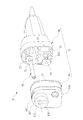
- the connector 25 has an outer case 61, a shield case 62 (see FIG. 6), a wireless communication unit 63, a wireless power receiving unit 64, and a light guide rod 65.
- connection posture the posture in which the connector 25 is correctly connected to the light source device 14 is defined as the “connection posture”
- connection direction in which the connector 25 is connected to the light source device 14 in the connection posture is defined as the Z direction
- the vertical direction of the connector 25 in the connection posture is defined as the Y direction
- the direction in the horizontal plane perpendicular to the Z direction and the Y direction is defined as the X direction.
- the positive side in the Z direction is the side where the light source device 14 is located when viewed from the connector 25, the positive side in the Y direction is vertically above, and the positive side in the X direction is the left side when viewed from the negative side in the Z direction to the positive side.
- the positive side in the Z direction which is the connection direction of the connector 25, may be referred to as the proximal end side, the proximal end portion, and the negative side in the Z direction may be referred to as the distal end side and the distal end portion.
- the exterior case 61 houses the wireless communication unit 63 and the wireless power receiving unit 64, and the light guide rod 65 protrudes from the front surface 61A located on the light source device 14 side in the connection posture.
- the wireless communication unit 63 wirelessly communicates with the light source device 14.
- the wireless power receiving unit 64 receives electric power wirelessly from the light source device 14. Since the position where the light guide rod 65 protrudes is the side located vertically above in the connection posture, the exterior case 61 houses the wireless communication unit 63 and the wireless power receiving unit 64 on the side located vertically below in the connection posture. do.
- the base end portion of the light guide rod 65 is provided with a fitting convex portion 61B that fits with the fitting concave portion 41D of the connector 41 on the light source device side, and the fitting convex portion 61B protrudes from the front surface 61A.
- the central axis LLG of the light guide rod 65 is parallel to the Z direction.
- the light guide rod 65 is arranged at the center of the front surface 61A in the X direction. Further, in the exterior case 61, the upper surface 61C located vertically above in the connection posture is a curved surface, and the lower surface 61D located vertically below in the connection posture is a flat surface. The light guide rod 65 is provided on the upper surface 61C side of the front surface 61A. On the other hand, the wireless communication unit 63 and the wireless power receiving unit 64 are housed side by side on the lower surface 61D side of the front surface 61A.
- the wireless communication unit 63 includes an image signal transmission unit 66 (see FIG. 2). Electronic components such as a substrate constituting the image signal transmission unit 66 are housed inside a metal shield case 62.
- the image signal transmission unit 66 wirelessly transmits an image signal obtained by imaging an observation target irradiated with illumination light to the image signal reception unit 46 of the light source device 14.
- the wireless communication performed by the wireless communication unit 63 is optical communication, and is preferably near-infrared communication using, for example, near-infrared light (light having a wavelength of about 0.7 ⁇ m to 2.5 ⁇ m).
- the wireless communication unit 63 has a connection pin 63A.
- the connection pin 63A has an optical signal emission end at the tip thereof, and by connecting the connection pin 63A to the connection hole 44A of the light source device side connector 41, transmission / reception of an optical signal to and from the wireless communication unit 44 of the light source device 14 can be performed. It will be possible.
- the optical signal of the image signal transmitting unit 66 is lightly transmitted to the image signal receiving unit 46 of the light source device 14 in a non-contact manner.
- the image signal optically transmitted to the image signal receiving unit 46 is transmitted to the processor device 16.
- the image signal transmitted from the endoscope 12 to the processor device 16 via the light source device 14 is subjected to image processing and displayed on the monitor 18 as an endoscope image.
- the functions of the wireless communication unit 44 of the light source device 14 and the wireless communication unit 63 of the connector 25 are not limited to those described above, and for example, control signals for controlling the image pickup sensor 33 of the endoscope 12 and the like are transmitted and received.
- the wireless power receiving unit 64 is, for example, a coil (so-called secondary coil), and receives power from a wireless power feeding unit 45 provided in the light source device 14 by a non-contact power transmission method.
- the wireless power receiving unit 64 is fixed to the shield case 62. Since an endoscope that supplies electric power by using a primary coil and a secondary coil is known in Japanese Patent Application Laid-Open No. 2016-67534, detailed description thereof will be omitted here. As shown in FIG. 5, since the wireless power receiving unit 64 is provided behind the front surface 61A, it passes through the front surface 61A and receives power from the light source device 14.
- the wireless power receiving unit 64 supplies electric power to each unit of the endoscope 12 such as the image pickup sensor 33.
- the connector 25 When the connector 25 is connected to the connector 41 on the light source device side, the connector 25 is locked and the connection is maintained by locking the connector 25 on the upper surface 61C and the lower surface 61D of the outer case 61.
- the light source device side connector 41 is provided with locking portions 41A and 41B.
- the upper surface 61C of the connector 25 is provided with a groove 61E into which the locking portion 41A of the light source device 14 is fitted
- the lower surface 61D of the connector 25 is provided with a groove 61F into which the locking portion 41B of the light source device 14 is fitted. Has been done.
- the outer case 61 has a case main body 68 and a case lid 69, and is formed in a hollow shape by connecting the case lid 69 to the base end portion of the case main body 68.
- the case body 68 and the case lid 69 constituting the outer case 61 are made of resin having high heat resistance and chemical resistance.
- the case lid 69 is provided with the above-mentioned front surface 61A and fitting convex portion 61B, and has a part of the upper surface 61C and the lower surface 61D.
- An O-ring 71 which is a sealing member, is fitted on the outer peripheral surface of the rear end portion of the case lid 69.
- the O-ring 71 is one of a plurality of sealing members that seal the inside of the outer case 61.
- a lead-out hole 61G for leading the light guide rod 65 to the outside is formed in the central portion of the fitting convex portion 61B.
- the base end of the light guide rod 65 is fixed to a bracket 72 arranged inside the outer case 61.
- the bracket 72 is formed in an L shape and is fixed to the inside of the case body 68.
- the light guide rod 65 is supported by the case body 68 and the case lid 69 by fixing the bracket 72 to the inner peripheral surface 69A (see FIG. 7) of the case lid 69.
- An elastic O-ring 73 is fitted on the outer peripheral surface of the light guide rod 65, and the light guide rod 65 is fitted into the lead-out hole 61G via the O-ring 73.
- the O-ring 73 is also one of a plurality of sealing members that seal the inside of the outer case 61.
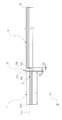
- the light guide rod 65 includes a first light guide rod 74 and a second light guide rod 75.
- the first light guide rod 74 and the second light guide rod 75 are formed in a cylindrical shape by a metal having high rigidity or the like.
- the first light guide rod 74 houses the incident window 76, the first light guide 51, the second light guide 52, and the lens member 53 inside.
- the incident window 76 is a transparent cover glass and is fixed to the base end portion of the first light guide rod 74.
- the illumination light from the light source unit 42 passes through the incident window 76, and the illumination light is incident on the first light guide 51.
- An elastic O-ring 81 is fitted to the inner peripheral surface of the base end portion of the first light guide rod 74. The O-ring 81 is deformed between the incident window 76 and the first light guide rod 74 and is in close contact with both, thereby ensuring airtightness at the base end portion of the first light guide rod 74.
- the first light guide 51 is held by the first ferrule 77
- the second light guide 52 is held by the second ferrule 78
- the lens member 53 is held by the spacer 79
- the first light guide rod 74 is held. It is fixed inside.
- the first ferrule 77 has a cylindrical shape provided with a light guide insertion hole 77A penetrating along the axial direction at the center.
- the first light guide 51 is inserted into the light guide insertion hole 77A.
- the first light guide 51 is, for example, adhered with an adhesive or the like and fixed to the light guide insertion hole 77A.
- An elastic O-ring 82 is fitted on the outer peripheral surface of the first ferrule 77.
- the first ferrule 77 together with the first light guide 51 and the O-ring 82, is inserted from the tip end side of the first light guide rod 74 to a position close to the incident window 76, and fits into the inner peripheral surface of the first light guide rod 74. Will be combined.
- the first light guide 51 is fixed to the first light guide rod 74 together with the first ferrule 77.
- the O-ring 82 is deformed between the first ferrule 77 and the first light guide rod 74 and is in close contact with both, thereby ensuring the airtightness between the first ferrule 77 and the first light guide rod 74. Will be done.
- the second ferrule 78 has a cylindrical shape provided with a light guide insertion hole 78A penetrating along the axial direction in the center.
- the base end portion of the second light guide 52 is inserted into the light guide insertion hole 78A.
- the second light guide 52 projects from the tip side of the light guide insertion hole 78A, passes through the second light guide rod 75, the connector 25, the universal cable 23, the grip portion 22, and the insertion portion 21, and passes through the tip portion of the endoscope 12. It is fixed at 21A.
- the base end portion of the second light guide 52 is adhered with, for example, an adhesive or the like and fixed to the light guide insertion hole 78A.
- the second ferrule 78 is provided with an opening 78B on the base end surface facing the first ferrule 77.
- the opening 78B is a circular opening having an inner diameter larger than that of the light guide insertion hole 78A.
- a spacer 79 is fitted in the opening 78B.
- a locking groove 78C is formed in the opening 78B.
- the outer peripheral surface of the second ferrule 78 has a large diameter portion 78D having an outer diameter one step larger and a small diameter portion 78E having an outer diameter smaller than that of the large diameter portion 78D.
- the large diameter portion 78D is fitted to the inner peripheral surface of the first light guide rod 74.
- the base end portion of the second light guide 52 is fixed to the first light guide rod 74 together with the second ferrule 78.
- the base end of the second light guide 52 projects from the base end side of the light guide insertion hole 78A into the opening 78B.
- the small diameter portion 78E has a gap between the small diameter portion 78E and the inner peripheral surface of the first light guide rod 74.
- the spacer 79 has a disk shape in which a through hole 79A penetrating along the axial direction is provided in the center.
- the spacer 79 has a lens member holding portion 79B and an O-ring accommodating portion 79C on the distal end side of the through hole 79A.
- the lens member holding portion 79B is an opening that is one size larger than the through hole 79A, and the inner diameter is formed according to the outer diameter of the lens member 53.
- the lens member holding portion 79B holds the lens member 53 by fitting the outer peripheral surface of the lens member 53.
- the O-ring storage portion 79C is an opening having an inner diameter slightly larger than that of the lens member holding portion 79B.
- the O-ring storage unit 79C stores the O-ring 83 having elasticity inside.
- the inner diameter of the O-ring 83 is smaller than the outer diameter of the lens member 53 and the outer diameter of the base end portion of the second light guide 52.
- the spacer 79 has a locked portion 79E formed on the outer peripheral surface 79D.
- the locked portion 79E may be an annular protrusion along the outer peripheral surface 79D, or may be a plurality of protrusions protruding from the outer peripheral surface 79D.
- the locked portion 79E is locked in the locking groove 78C of the opening 78B.
- the outer peripheral surface 79D of the spacer 79 is formed so as to match the inner peripheral surface of the opening 78B.
- the spacer 79 is fixed to the opening 78B of the second ferrule 78 in a state where the lens member 53 is held in the lens member holding portion 79B and the O-ring 83 is housed in the O-ring storage portion 79C.
- the outer peripheral surface 79D is fitted to the inner peripheral surface of the opening 78B, and the locked portion 79E is locked to the locking groove 78C.
- the spacer 79 is restricted in position with respect to the opening 78B, so that the spacer 79 does not separate from the opening 78B.
- the base end of the second light guide 52 protrudes inside the opening 78B. Therefore, when the spacer 79 is fixed to the opening 78B of the second ferrule 78, the proximal end of the second light guide 52 projects into the spacer 79 and presses the O-ring 83 toward the proximal end side. The lens member 53 is pressed against the base end side of the spacer 79 by the pressing received from the second light guide 52 via the O-ring 83.
- the lens member 53 is fixed to the second ferrule 78 via the spacer 79, and further fixed to the first light guide rod 74 by fitting the second ferrule 78 to the first light guide rod 74.
- the lens member 53 is pressed toward the proximal end side by the O-ring 83 and is in contact with the edge of the through hole 79A. As a result, the position of the lens member 53 in the axial direction with respect to the spacer 79 is restricted.
- the second light guide rod 75 is connected to the tip end side of the first light guide rod 74.
- the second light guide rod 75 has a fitting portion 75A at the base end portion.
- the fitting portion 75A is formed to have an outer diameter smaller than the outer peripheral surface of the portion having the largest outer diameter of the second light guide rod 75, and is fitted to the inner peripheral surface of the first light guide rod 74.
- the end portion 75B on the most base end side of the fitting portion 75A is formed to have a small thickness, and is formed between the small diameter portion 78E of the second ferrule 78 and the inner peripheral surface of the first light guide rod 74. It is inserted into the gap.
- the connection between the first light guide rod 74 and the second light guide rod 75 is not limited to this, and any configuration may be used as long as the two can be connected by using an adhesive or a connecting member.
- an elastic O-ring 84 is fitted to the fitting portion 75A.
- the O-ring 84 is deformed between the inner peripheral surface of the first light guide rod 74 and the fitting portion 75A, and is in close contact with both of them, so that the O-ring 84 is between the first light guide rod 74 and the second light guide rod 75. Airtightness is ensured.
- the temperature and pressure are high. Prevents saturated water vapor from entering the inside of the first light guide rod 74 and the second light guide rod 75.
- the first light guide 51, the second light guide 52, and the lens member 53 are fixed to the inside of the first light guide rod 74 via the first ferrule 77, the second ferrule 78, and the spacer 79.
- the lens As a result, the lens member 53 is arranged between the first light guide 51 and the second light guide 52. Further, since the first light guide 51, the second light guide 52, and the lens member 53 are held at the centers of the first ferrule 77, the second ferrule 78, and the spacer 79, respectively, the central axis LLG of the light guide rod 65. And the central axes of the first light guide 51, the second light guide 52, and the lens member 53 coincide with each other.
- the lens member 53 is a plano-convex lens in which the lens surface 53A on the incident side is planar and the lens surface 53B on the exit side is convex.
- the lens member 53 may be a biconvex lens, a meniscus lens, or the like.
- the lens member 53 preferably has an antireflection film called an AR (anti-reflective coating) coating formed on the lens surfaces 53A and 53B. This makes it possible to further prevent a decrease in the amount of illumination light in the light guide unit 26.
- FIG. 10 shows the positional relationship between the first light guide 51, the second light guide 52, and the lens member 53 constituting the light guide unit 26, and the first light guide is to prevent the drawing from being complicated. The covering of the 51 and the second light guide 52 is omitted.
- the position of the lens member 53 in the axial direction is restricted because the lens surface 53A abuts on the edge of the through hole 79A and the lens surface 53B is pressed by the O-ring 83.
- the lens surfaces 53A and 53B of the lens member 53 are arranged at intervals from the exit end 51B of the first light guide 51 and the incident end 52A of the second light guide 52.
- the lens surface 53A has a gap D1 with respect to the emission end 51B of the first light guide 51.
- the gap D1 is preferably larger than 0 mm and preferably 0.5 mm or less.
- the lens surface 53B has a gap D2 with respect to the incident end 52A of the second light guide 52.
- the gap D2 is preferably larger than 0 mm and preferably 0.5 mm or less.
- the light guide portion 26 in the present embodiment has a circular end surface at the incident end 51A of the first light guide 51 facing the light source portion 42, but as shown in FIG.
- the emission end 28 of the second light guide 52 in the tip portion 21A is formed in an arc shape located around the observation portion 27 for the convenience of arranging the parts of the tip portion 21A. Therefore, it is difficult to arrange the lens member 53 on the tip portion 21A.
- the inside of the light guide rod 65 is easy to arrange because there is no component that hinders the arrangement of the lens member 53.
- the first light guide 51 and the lens member 53 are arranged so that the light emitting point of the first light guide 51 is closer to the lens surface 53A than the focal point P on the incident side of the lens member 53.
- the illumination light emitted from the light emitting point of the first light guide 51 travels in a diffused direction when passing through the lens member 53. Therefore, the light guide unit 26 using the lens member 53 can obtain the effects of preventing a decrease in the amount of light and preventing deterioration of the light distribution.
- the first light guide 51 forms a light emitting point at the emission end 51B. Therefore, it is preferable that the first light guide 51 has a dimension L1 of 5 mm or more in the axial direction from the incident end 51A to the emitted end 51B.
- the lens member 53 is a lens guided by the first light guide 51 and the second light guide 52 to prevent a decrease in the amount of light and a deterioration in the light distribution of the illumination light emitted from the emission end 28.
- the lens member 53 is guided by the first light guide 51 and the second light guide 52, and suppresses variations in the relative intensity of each color of the illumination light emitted from the emission end 28 with respect to the light distribution angle. It is a lens.
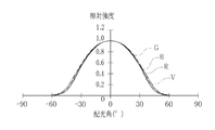
- the graphs shown in FIGS. 13 and 14 show the positions of the light guide portion 26 before the illumination light passes through the lens member 53 (FIG. 13) and the positions after the illumination light passes through the lens member 53 (FIG. 14).
- the relative intensity referred to here is expressed as a ratio of the light intensity of each color of LED light when the light distribution angle is 0 ° to 1 and the light intensity other than the light distribution angle of 0 ° to the light intensity at 0 °. It was done.
- the light intensity is the density within the unit solid angle of the luminous flux of light.
- the light source unit 42 emits light and the light guide unit 26 guides the LED light.
- the purple light V, the blue light B, the green light G, and the red light R have variations in relative intensity with respect to the light distribution angle. In particular, there is a large variation in relative intensity when the light distribution angle is around ⁇ 25 °.
- the light source unit 42 emits light and the light guide unit 26 guides the light.
- the purple light V, the blue light B, the green light G, and the red light R which are the LED lights, have the same relative intensities with respect to the light distribution angle. That is, it is possible to suppress variations in relative strength.
- the fact that the relative intensities match here means that the difference in the relative intensities of each color with respect to the light distribution angle is very small, and when the relative intensities of the green light G are used as a reference, the purple light V and the blue light B are used.
- the relative intensities of the red light R are all within ⁇ 5% of the relative intensities of the green light G.
- the light guide unit 26 is composed of the first light guide 51, the second light guide 52, and the lens member 53, and the first light guide 51, the second light guide 52, and the lens member. 53 is fixed to the inside of the first light guide rod 74 having rigidity. Therefore, the positions of the optical axes of the first light guide 51, the second light guide 52, and the lens member 53 do not shift. Therefore, regardless of the operating state of the endoscope 12, the light guide unit 26 can prevent a decrease in the amount of illumination light and a deterioration in the light distribution by the lens member 53.
- the endoscope 12 needs to be sterilized each time it is used. In this case, it is common to perform sterilization using an autoclave. During this sterilization process, the connector 25 including the light guide rod 65 is exposed to saturated steam at high temperature and high pressure (for example, 135 ° C., 5 atm) for about 20 minutes.
- high temperature and high pressure for example, 135 ° C., 5 atm
- the lens member 53 is in contact with the first light guide 51 and the second light guide 52, when the sterilization process by the autoclave is repeatedly performed, the coefficient of thermal expansion of the lens member 53 and the first light guide 51 and Due to the difference from the coefficient of thermal expansion of the second light guide 52, the lens member 53 may be scratched by being pressed by the first light guide 51 and the second light guide 52.
- the lens member 53 since the lens member 53 has gaps D1 and D2 with respect to the end faces of the first light guide 51 and the second light guide 52, the lens member 53 is sterilized even if the endoscope 12 is sterilized.
- the first light guide 51 and the second light guide 52 do not come into contact with each other, and the lens member 53 is not scratched.
- the adhesive used for fixing the first light guide 51 and the second light guide 52 does not adhere to the lens member 53.
- the lens member 53 for reducing the amount of light and deteriorating the light distribution is arranged inside the light guide rod 65
- the present invention is not limited to this, and the light guide rod 65 is excluded. It may be arranged inside the connector 25.
- the lens member 53 is arranged inside the outer case 91 constituting the connector 90.
- the configurations other than the connector 90 are the same as those of the endoscope system 10 of the first embodiment, and the same parts and the like are designated by the same reference numerals and the description thereof will be omitted.
- the connector 90 is provided at the base end of the universal cable 23 and is detachably connected to the light source device side connector 41 of the light source device 14.
- the connector 90 includes an exterior case 91, a light guide rod 92, and a lens member holding portion 93.
- the exterior case 91 houses the wireless communication unit 63, the wireless power receiving unit 64, and the like in the exterior case 61 of the connector 25 of the first embodiment, and is a light guide rod from the front surface 61A located on the light source device 14 side. 92 is protruding.
- the light guide rod 92 holds only the first light guide 51, and does not hold the second light guide 52 and the lens member 53.
- the lens member holding portion 93 is the same as the first light guide rod 74 of the first embodiment, via the first ferrule 77, the second ferrule 78, and the spacer 79, and the first light guide 51 and the second light guide 52. , And the lens member 53 are fixed inside. As a result, the lens member 53 is arranged between the first light guide 51 and the second light guide 52. Further, as in the first embodiment, the incident end 51A of the first ride guide 51 faces the light source portion 42, and the exit end 28 of the second light guide 52 is located at the tip portion 21A. Therefore, the light guide unit 26 guides the illumination light generated by the light source unit 42 to the tip portion 21A of the endoscope 12.
- an O-ring 83 is housed inside the spacer 79, and the O-ring 83 is sandwiched between the lens member 53 and the second light guide 52 as in the first embodiment. Therefore, the lens member 53 and the second light guide 52 are arranged at a distance from each other.
- the lens member holding portion 93 is fixed to the inside of the outer case 91.
- the outer case 91 and the lens member holding portion 93 are made of, for example, resin parts and have high rigidity. Further, an O-ring or the like (not shown) is provided in the gap between the parts constituting the outer case 91 to ensure airtightness. Therefore, the lens member holding portion 93 does not require a structure for ensuring airtightness. That is, unlike the first light guide rod 74 of the first embodiment, it is not necessary to provide O-rings 81, 82, 84 and the like for ensuring airtightness, and the number of parts can be reduced.
- the light guide unit 26 can prevent a decrease in the amount of illumination light and a deterioration in the light distribution by the lens member 53 regardless of the operating state of the endoscope.
- the present invention is not limited to this, and the endoscope is not limited to this. May be configured and placed inside other rigid components.
- the operation unit 102 connected to the insertion unit 101 is provided, and the lens member 53 is arranged inside the operation unit 102.
- the configurations other than the endoscope 100 are the same as those of the endoscope system 10 of the first embodiment, and the same parts and the like are designated by the same reference numerals and the description thereof will be omitted.
- the endoscope 100 is a rigid endoscope such as a laparoscope, and has an elongated rigid insertion portion 101 inserted into a subject and an insertion portion 101. It is provided with an operation unit 102 connected to the base end portion of the above and a flexible universal cable 23 connected to the operation unit 102.
- a connector 103 is provided at the base end of the universal cable 23, and the endoscope 100 is detachably connected to the light source device side connector 41 of the light source device 14 via the connector 103. Note that, unlike the connectors 25 and 90 of the first and second embodiments, the connector 103 holds only the first light guide 51, and does not hold the second light guide 52 and the lens member 53.
- the insertion portion 101 has a tip portion 101A and a curved portion 101B.
- the tip portion 101A is provided with an observation portion 27 and an emission end 28, similarly to the tip portion 21A of the endoscope 12 of the first embodiment.
- the curved portion 101B is continuously provided at the tip portion 101A and is provided so as to be bendable.
- the operation unit 102 is provided with a bending operation lever 102A, an operation button (not shown), and the like.
- the bending operation lever 102A is an operation member for bending the bending portion 101B. By bending the curved portion 101B, the direction of the tip portion 101A can be changed.
- the operation unit 102 is composed of, for example, resin parts and has high rigidity. It is preferable that the lens member 53 is provided inside the endoscope 100 at a position other than the curved portion 101B. More specifically, the lens member 53 is provided inside the operation unit 102. Similar to the lens member holding portion 93 in the second embodiment, the operating portion 102 has a holding portion (not shown) in which the first light guide 51, the second light guide 52, and the lens member 53 are fixed internally. Are provided integrally.
- the lens member 53 is provided on the curved portion 101B, if the curved portion 101B is curved, the positions of the optical axes of the first light guide 51, the second light guide 52, and the lens member 53 are displaced.
- the lens member 53 is provided inside the operation unit 102. Since the operation unit 102 has rigidity, the positions of the optical axes of the first light guide 51, the second light guide 52, and the lens member 53 do not shift. Therefore, as in the first embodiment, the light guide unit 26 can prevent a decrease in the amount of illumination light and a deterioration in the light distribution by the lens member 53 regardless of the operating state of the endoscope.
- an endoscope used as a laparoscope has been described as an example, but the present invention may be applied to an endoscope used for other purposes such as industrial use. can.
Landscapes
- Health & Medical Sciences (AREA)
- Life Sciences & Earth Sciences (AREA)
- Surgery (AREA)
- Physics & Mathematics (AREA)
- Engineering & Computer Science (AREA)
- Optics & Photonics (AREA)
- Biomedical Technology (AREA)
- General Health & Medical Sciences (AREA)
- Pathology (AREA)
- Nuclear Medicine, Radiotherapy & Molecular Imaging (AREA)
- Biophysics (AREA)
- Heart & Thoracic Surgery (AREA)
- Medical Informatics (AREA)
- Molecular Biology (AREA)
- Animal Behavior & Ethology (AREA)
- Radiology & Medical Imaging (AREA)
- Public Health (AREA)
- Veterinary Medicine (AREA)
- Computer Networks & Wireless Communication (AREA)
- Astronomy & Astrophysics (AREA)
- General Physics & Mathematics (AREA)
- Endoscopes (AREA)
- Instruments For Viewing The Inside Of Hollow Bodies (AREA)
Priority Applications (4)
| Application Number | Priority Date | Filing Date | Title |
|---|---|---|---|
| JP2022534906A JP7447268B2 (ja) | 2020-07-08 | 2021-03-18 | 内視鏡システム |
| CN202180048555.1A CN115776862B (zh) | 2020-07-08 | 2021-03-18 | 内窥镜系统 |
| DE112021003652.1T DE112021003652T5 (de) | 2020-07-08 | 2021-03-18 | Endoskopsystem |
| US18/148,912 US20230135724A1 (en) | 2020-07-08 | 2022-12-30 | Endoscope system |
Applications Claiming Priority (2)
| Application Number | Priority Date | Filing Date | Title |
|---|---|---|---|
| JP2020117762 | 2020-07-08 | ||
| JP2020-117762 | 2020-07-08 |
Related Child Applications (1)
| Application Number | Title | Priority Date | Filing Date |
|---|---|---|---|
| US18/148,912 Continuation US20230135724A1 (en) | 2020-07-08 | 2022-12-30 | Endoscope system |
Publications (1)
| Publication Number | Publication Date |
|---|---|
| WO2022009480A1 true WO2022009480A1 (ja) | 2022-01-13 |
Family
ID=79552852
Family Applications (1)
| Application Number | Title | Priority Date | Filing Date |
|---|---|---|---|
| PCT/JP2021/011184 Ceased WO2022009480A1 (ja) | 2020-07-08 | 2021-03-18 | 内視鏡システム |
Country Status (5)
| Country | Link |
|---|---|
| US (1) | US20230135724A1 (https=) |
| JP (1) | JP7447268B2 (https=) |
| CN (1) | CN115776862B (https=) |
| DE (1) | DE112021003652T5 (https=) |
| WO (1) | WO2022009480A1 (https=) |
Families Citing this family (2)
| Publication number | Priority date | Publication date | Assignee | Title |
|---|---|---|---|---|
| EP3677163B1 (en) * | 2017-08-31 | 2022-12-28 | FUJIFILM Corporation | Connector device for endoscopes |
| NL2026240B1 (en) * | 2020-08-07 | 2022-04-08 | Limis Dev B V | Device for coupling coherent light into an endoscopic system |
Citations (4)
| Publication number | Priority date | Publication date | Assignee | Title |
|---|---|---|---|---|
| JPH06296584A (ja) * | 1993-04-19 | 1994-10-25 | Olympus Optical Co Ltd | 内視鏡 |
| JPH09292575A (ja) * | 1996-02-26 | 1997-11-11 | Olympus Optical Co Ltd | 内視鏡tv観察システム |
| JP2000131521A (ja) * | 1998-10-27 | 2000-05-12 | Olympus Optical Co Ltd | 干渉膜およびこれを用いた撮像装置 |
| JP2001120495A (ja) * | 1999-10-26 | 2001-05-08 | Asahi Optical Co Ltd | 電子内視鏡システムに用いる照明用光ケーブル |
Family Cites Families (8)
| Publication number | Priority date | Publication date | Assignee | Title |
|---|---|---|---|---|
| JP5554288B2 (ja) | 2011-06-13 | 2014-07-23 | 富士フイルム株式会社 | 内視鏡システム、プロセッサ装置及び画像補正方法 |
| EP2815691A4 (en) * | 2012-11-07 | 2015-11-25 | Olympus Corp | ENDOSCOPE |
| JP2015206912A (ja) * | 2014-04-21 | 2015-11-19 | オリンパス株式会社 | 光ファイバの接続アダプタおよび内視鏡装置 |
| JP2015211727A (ja) | 2014-05-01 | 2015-11-26 | オリンパス株式会社 | 内視鏡装置 |
| JP5877289B1 (ja) * | 2014-06-09 | 2016-03-02 | オリンパス株式会社 | 内視鏡システム |
| JP6106142B2 (ja) | 2014-09-29 | 2017-03-29 | 富士フイルム株式会社 | 内視鏡システム、内視鏡、および内視鏡用コネクタ |
| JPWO2017216878A1 (ja) * | 2016-06-14 | 2019-04-11 | オリンパス株式会社 | 内視鏡装置 |
| WO2018235166A1 (ja) | 2017-06-20 | 2018-12-27 | オリンパス株式会社 | 内視鏡システム |
-
2021
- 2021-03-18 JP JP2022534906A patent/JP7447268B2/ja active Active
- 2021-03-18 DE DE112021003652.1T patent/DE112021003652T5/de active Pending
- 2021-03-18 CN CN202180048555.1A patent/CN115776862B/zh active Active
- 2021-03-18 WO PCT/JP2021/011184 patent/WO2022009480A1/ja not_active Ceased
-
2022
- 2022-12-30 US US18/148,912 patent/US20230135724A1/en active Pending
Patent Citations (4)
| Publication number | Priority date | Publication date | Assignee | Title |
|---|---|---|---|---|
| JPH06296584A (ja) * | 1993-04-19 | 1994-10-25 | Olympus Optical Co Ltd | 内視鏡 |
| JPH09292575A (ja) * | 1996-02-26 | 1997-11-11 | Olympus Optical Co Ltd | 内視鏡tv観察システム |
| JP2000131521A (ja) * | 1998-10-27 | 2000-05-12 | Olympus Optical Co Ltd | 干渉膜およびこれを用いた撮像装置 |
| JP2001120495A (ja) * | 1999-10-26 | 2001-05-08 | Asahi Optical Co Ltd | 電子内視鏡システムに用いる照明用光ケーブル |
Also Published As
| Publication number | Publication date |
|---|---|
| JP7447268B2 (ja) | 2024-03-11 |
| DE112021003652T5 (de) | 2023-04-27 |
| JPWO2022009480A1 (https=) | 2022-01-13 |
| CN115776862B (zh) | 2025-12-23 |
| US20230135724A1 (en) | 2023-05-04 |
| CN115776862A (zh) | 2023-03-10 |
Similar Documents
| Publication | Publication Date | Title |
|---|---|---|
| US7063663B2 (en) | Endoscopic system with a solid-state light source | |
| EP3239760B1 (en) | Light device and system for providing light to optical scopes | |
| US6730019B2 (en) | Endoscope with LED illumination | |
| EP2967299B1 (en) | Endoscopic light source and imaging system | |
| EP2514352B1 (en) | Endoscope | |
| US20030107652A1 (en) | Dental video camera | |
| US20060069314A1 (en) | Solid state illumination for endoscopy | |
| JPH10216085A (ja) | 内視鏡 | |
| US20150157194A1 (en) | Endoscope | |
| AU2018309165B2 (en) | Medical Illumination Device and Related Methods | |
| US20230135724A1 (en) | Endoscope system | |
| JPWO2022009480A5 (https=) | ||
| JP2022079732A (ja) | 位置調整方法 | |
| JP6438830B2 (ja) | 位置調整方法 | |
| US12396629B2 (en) | Endoscope light source device and light quantity adjusting method | |
| US20070039077A1 (en) | Endoscope | |
| US12440090B2 (en) | Endoscope and endoscope system | |
| JP7054401B2 (ja) | 内視鏡用光源装置 | |
| JP2019030743A (ja) | 内視鏡用光源装置、内視鏡システム、及び位置調整方法 | |
| US20250288187A1 (en) | Medical observation system, light source device, light guide cable, and observation device | |
| JPH119542A (ja) | 内視鏡 |
Legal Events
| Date | Code | Title | Description |
|---|---|---|---|
| 121 | Ep: the epo has been informed by wipo that ep was designated in this application |
Ref document number: 21837838 Country of ref document: EP Kind code of ref document: A1 |
|
| ENP | Entry into the national phase |
Ref document number: 2022534906 Country of ref document: JP Kind code of ref document: A |
|
| 122 | Ep: pct application non-entry in european phase |
Ref document number: 21837838 Country of ref document: EP Kind code of ref document: A1 |