WO2022009480A1 - 内視鏡システム - Google Patents
内視鏡システム Download PDFInfo
- Publication number
- WO2022009480A1 WO2022009480A1 PCT/JP2021/011184 JP2021011184W WO2022009480A1 WO 2022009480 A1 WO2022009480 A1 WO 2022009480A1 JP 2021011184 W JP2021011184 W JP 2021011184W WO 2022009480 A1 WO2022009480 A1 WO 2022009480A1
- Authority
- WO
- WIPO (PCT)
- Prior art keywords
- light
- light guide
- endoscope
- light source
- lens member
- Prior art date
Links
Images


Classifications
-
- A—HUMAN NECESSITIES
- A61—MEDICAL OR VETERINARY SCIENCE; HYGIENE
- A61B—DIAGNOSIS; SURGERY; IDENTIFICATION
- A61B1/00—Instruments for performing medical examinations of the interior of cavities or tubes of the body by visual or photographical inspection, e.g. endoscopes; Illuminating arrangements therefor
- A61B1/00064—Constructional details of the endoscope body
- A61B1/00071—Insertion part of the endoscope body
- A61B1/0008—Insertion part of the endoscope body characterised by distal tip features
- A61B1/00096—Optical elements
-
- A—HUMAN NECESSITIES
- A61—MEDICAL OR VETERINARY SCIENCE; HYGIENE
- A61B—DIAGNOSIS; SURGERY; IDENTIFICATION
- A61B1/00—Instruments for performing medical examinations of the interior of cavities or tubes of the body by visual or photographical inspection, e.g. endoscopes; Illuminating arrangements therefor
- A61B1/06—Instruments for performing medical examinations of the interior of cavities or tubes of the body by visual or photographical inspection, e.g. endoscopes; Illuminating arrangements therefor with illuminating arrangements
- A61B1/07—Instruments for performing medical examinations of the interior of cavities or tubes of the body by visual or photographical inspection, e.g. endoscopes; Illuminating arrangements therefor with illuminating arrangements using light-conductive means, e.g. optical fibres
-
- A—HUMAN NECESSITIES
- A61—MEDICAL OR VETERINARY SCIENCE; HYGIENE
- A61B—DIAGNOSIS; SURGERY; IDENTIFICATION
- A61B1/00—Instruments for performing medical examinations of the interior of cavities or tubes of the body by visual or photographical inspection, e.g. endoscopes; Illuminating arrangements therefor
- A61B1/00002—Operational features of endoscopes
- A61B1/00011—Operational features of endoscopes characterised by signal transmission
- A61B1/00016—Operational features of endoscopes characterised by signal transmission using wireless means
-
- A—HUMAN NECESSITIES
- A61—MEDICAL OR VETERINARY SCIENCE; HYGIENE
- A61B—DIAGNOSIS; SURGERY; IDENTIFICATION
- A61B1/00—Instruments for performing medical examinations of the interior of cavities or tubes of the body by visual or photographical inspection, e.g. endoscopes; Illuminating arrangements therefor
- A61B1/00112—Connection or coupling means
- A61B1/00121—Connectors, fasteners and adapters, e.g. on the endoscope handle
- A61B1/00126—Connectors, fasteners and adapters, e.g. on the endoscope handle optical, e.g. for light supply cables
-
- A—HUMAN NECESSITIES
- A61—MEDICAL OR VETERINARY SCIENCE; HYGIENE
- A61B—DIAGNOSIS; SURGERY; IDENTIFICATION
- A61B1/00—Instruments for performing medical examinations of the interior of cavities or tubes of the body by visual or photographical inspection, e.g. endoscopes; Illuminating arrangements therefor
- A61B1/005—Flexible endoscopes
-
- A—HUMAN NECESSITIES
- A61—MEDICAL OR VETERINARY SCIENCE; HYGIENE
- A61B—DIAGNOSIS; SURGERY; IDENTIFICATION
- A61B1/00—Instruments for performing medical examinations of the interior of cavities or tubes of the body by visual or photographical inspection, e.g. endoscopes; Illuminating arrangements therefor
- A61B1/06—Instruments for performing medical examinations of the interior of cavities or tubes of the body by visual or photographical inspection, e.g. endoscopes; Illuminating arrangements therefor with illuminating arrangements
- A61B1/0638—Instruments for performing medical examinations of the interior of cavities or tubes of the body by visual or photographical inspection, e.g. endoscopes; Illuminating arrangements therefor with illuminating arrangements providing two or more wavelengths
-
- A—HUMAN NECESSITIES
- A61—MEDICAL OR VETERINARY SCIENCE; HYGIENE
- A61B—DIAGNOSIS; SURGERY; IDENTIFICATION
- A61B1/00—Instruments for performing medical examinations of the interior of cavities or tubes of the body by visual or photographical inspection, e.g. endoscopes; Illuminating arrangements therefor
- A61B1/06—Instruments for performing medical examinations of the interior of cavities or tubes of the body by visual or photographical inspection, e.g. endoscopes; Illuminating arrangements therefor with illuminating arrangements
- A61B1/0661—Endoscope light sources
- A61B1/0669—Endoscope light sources at proximal end of an endoscope
-
- G—PHYSICS
- G02—OPTICS
- G02B—OPTICAL ELEMENTS, SYSTEMS OR APPARATUS
- G02B23/00—Telescopes, e.g. binoculars; Periscopes; Instruments for viewing the inside of hollow bodies; Viewfinders; Optical aiming or sighting devices
- G02B23/24—Instruments or systems for viewing the inside of hollow bodies, e.g. fibrescopes
- G02B23/26—Instruments or systems for viewing the inside of hollow bodies, e.g. fibrescopes using light guides
-
- A—HUMAN NECESSITIES
- A61—MEDICAL OR VETERINARY SCIENCE; HYGIENE
- A61B—DIAGNOSIS; SURGERY; IDENTIFICATION
- A61B1/00—Instruments for performing medical examinations of the interior of cavities or tubes of the body by visual or photographical inspection, e.g. endoscopes; Illuminating arrangements therefor
- A61B1/06—Instruments for performing medical examinations of the interior of cavities or tubes of the body by visual or photographical inspection, e.g. endoscopes; Illuminating arrangements therefor with illuminating arrangements
- A61B1/0655—Control therefor
-
- A—HUMAN NECESSITIES
- A61—MEDICAL OR VETERINARY SCIENCE; HYGIENE
- A61B—DIAGNOSIS; SURGERY; IDENTIFICATION
- A61B1/00—Instruments for performing medical examinations of the interior of cavities or tubes of the body by visual or photographical inspection, e.g. endoscopes; Illuminating arrangements therefor
- A61B1/06—Instruments for performing medical examinations of the interior of cavities or tubes of the body by visual or photographical inspection, e.g. endoscopes; Illuminating arrangements therefor with illuminating arrangements
- A61B1/0661—Endoscope light sources
- A61B1/0684—Endoscope light sources using light emitting diodes [LED]
Definitions
- the present invention relates to an endoscopic system.
- Endoscopes are widely used in the medical and industrial fields.
- the endoscope has an insertion portion to be inserted into the subject, and illuminates the observation target from the tip portion of the insertion portion.
- a light guide portion that guides the illumination light supplied from the light source device to the tip portion of the insertion portion is provided inside the endoscope.
- the light guide unit guides the illumination light and illuminates the observation target so that the inside of the subject can be observed.
- the light guide unit includes a plurality of light guides.
- the light guide is composed of, for example, a fiber bundle obtained by bundling a quartz fiber or a multi-component fiber. Among such fiber bundles, those made of quartz fibers are excellent in flexibility, but have a high light attenuation rate. Therefore, in the endoscope described in Patent Document 1, a lens is arranged between a plurality of light guides. By using this lens, the decrease in the amount of light and the deterioration of the light distribution are prevented, and the light from the end of the light guide on the light source side is transmitted to the end of the light guide on the tip side.
- some endoscopes are provided with a bendable portion at the tip of the insertion portion in order to observe the observation site at various angles and facilitate insertion.
- the end of the light guide and the lens are arranged inside the curved portion.
- An object of the present invention is to provide an endoscope system capable of preventing a decrease in the amount of illumination light and a deterioration in light distribution regardless of the operating state of the endoscope.
- the endoscope system of the present invention is an endoscope system including an endoscope having an insertion portion, an illumination light emitting end, and a light guide portion, and a light source device, and the light guide portion is a light guide.
- the optical member is provided in the inside of the endoscope, on the proximal end side of the illumination light emitting end, and at a position having rigidity.
- the insertion portion is inserted into the subject.
- the illumination light emitting end is provided at the tip of the insertion portion.
- the light guide unit guides the illumination light.
- the light source device is connected to an endoscope and has a plurality of light sources that emit different colored lights from each other, and emits illumination light in which a plurality of colored lights are mixed by the light sources.
- the light guide guides the illumination light from the light source to the illumination light emission end.
- the optical member is guided by a light guide and suppresses variation in the relative intensity of each color with respect to the light distribution angle of the illumination light emitted from the illumination light emission end.
- the light guide portion has a plurality of light guides
- the optical member is a lens member arranged between the plurality of light guides.
- the light guide and the lens member are arranged so that the emission point of the illumination light guided by the light guide is closer to the lens member than the focal point on the incident side of the lens member.
- the lens surface of the lens member is arranged at a distance from the exit end and the incident end of the light guide.
- the endoscope has a connector for connecting to the light source device, and the optical member is arranged inside the connector. It is more preferred that the connector has a light guide rod that is inserted inside the light source device when connected to the light source device, and the optical member is arranged inside the light guide rod.
- the insertion portion has a curved portion that changes the direction of the tip portion, and the optical member is provided inside the endoscope at a position other than the curved portion.
- the endoscope is provided with an operation unit connected to the insertion portion, and the optical member is provided in the operation unit.
- the light guide located on the incident side of the optical member preferably has a dimension of 5 mm or more from the incident end to the emitted end in the optical axis direction.
- the lens member preferably has an antireflection film formed on the lens surface.
- the lens member When the relative intensity of one color light is used as a reference among a plurality of color lights emitted by a light source, the lens member shall make the relative intensity of the other color light within ⁇ 5% of the relative intensity of the reference color light. Is preferable.
- the endoscope system of the present invention it is possible to prevent a decrease in the amount of illumination light and a deterioration in light distribution regardless of the operating state of the endoscope.
- FIG. 7 is a cross-sectional view of a main part showing a configuration around a lens member by enlarging a part of FIG. 7. It is a perspective view of a spacer member, a lens member, and an O-ring. It is explanatory drawing which shows the positional relationship of the 1st light guide, the 2nd light guide and a lens member.
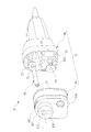
- the endoscope system 10 includes an endoscope 12, a light source device 14, a processor device 16, a monitor 18, and a console 20.
- the endoscope 12 is a rigid endoscope such as a laparoscope, and has an elongated rigid insertion portion 21 to be inserted into a subject and an L-shaped grip connected to the base end portion of the insertion portion 21.
- a flexible universal cable 23 whose base end portion is connected to the insertion portion 21 via the grip portion 22 and a switch arrangement member 24 provided in the middle portion of the universal cable 23 are provided.
- a connector 25 is provided at the base end of the universal cable 23, and the endoscope 12 is detachably connected to the light source device side connector 41 of the light source device 14 via the connector 25.
- the universal cable 23 includes a light guide unit 26 (see FIG. 2) that guides the illumination light emitted by the light source device 14, a control line that controls an image pickup sensor 33 provided at the tip portion 21A of the insertion unit 21, and illumination light. It is a cable in which a signal line for transmitting an image signal output by an image pickup sensor 33 when an image of an irradiated observation target is imaged, a power line for supplying power to each part of the image pickup sensor, and the like are integrated. In FIG. 2, the control line, the signal line, and the power line are omitted for the convenience of complication of the drawing.
- the endoscope 12 and the light source device 14 are configured to transmit power, optical signals, and the like in a non-contact manner via the connector 25 and the light source device side connector 41.
- the image displayed on the monitor 18 is a normal image and a special light image (for example, a WL (white Light) image, BLI (BLueLASER Imaging). )
- An image changeover switch for switching between an image, an LCI (LinkedCoLorImaging) image, or a low oxygen imaging image) can be applied.
- the present invention is not limited to this, and an image still switch, a shooting switch, a zoom switch having a tele and wide buttons, a cleaning switch at the tip of the insertion portion, a light light intensity adjustment switch, a sensitivity adjustment switch, and the like can also be applied.
- the tip portion 21A of the insertion portion 21 is provided with an observation unit 27 and an illumination light emission end (hereinafter, simply referred to as an emission end) 28.
- the observation unit 27 includes an observation window 29, an image pickup lens group 31 and a prism 32 arranged on the back of the observation window 29, and an image pickup sensor 33.
- the image pickup sensor 33 is, for example, a color sensor having a primary color filter, and has a B pixel (blue pixel) having a blue color filter, a G pixel (green pixel) having a green color filter, and an R having a red color filter. It has three types of pixels (red pixels). Blue color filters mainly transmit purple to blue light. Green color filters mainly transmit green light. Red color filters mainly transmit red light.
- Blue color filters mainly transmit purple to blue light.
- Green color filters mainly transmit green light.
- Red color filters mainly transmit red light.
- CMOS Complementary Metal Oxide Semiconductor
- image sensor 33 a CCD (Charge Coupled Device) type image sensor or a CMOS (Complementary Metal Oxide Semiconductor) image sensor can be applied.
- the image sensor 33 of the present embodiment is a primary color system color sensor, a complementary color system color sensor can also be used.
- Complementary color sensors include, for example, a cyan pixel provided with a cyan color filter, a magenta pixel provided with a magenta color filter, a yellow pixel provided with a yellow color filter, and a green pixel provided with a green color filter. Have.
- the image obtained from the pixels of each of the above colors can be converted into a B image, a G image, and an R image by performing complementary color-primary color conversion.
- a monochrome sensor without a color filter may be used as the image pickup sensor 33.
- an image of each of the above colors can be obtained by sequentially imaging the observation target using illumination light of each color such as BGR.
- the processor device 16 controls the amount and emission timing of the illumination light emitted by the light source device 14, the operation of the image pickup sensor 33, and the like, and uses an image signal obtained by imaging the observation target irradiated with the illumination light to obtain an endoscopic image. To generate. Further, the processor device 16 is electrically connected to the monitor 18 and the console 20. The monitor 18 displays an endoscope image generated by the processor device 16, information about the endoscope image, and the like.
- the console 20 is a user interface that accepts input operations such as function settings.
- the light source device 14 includes a light source unit 42, a light source control unit 43, a wireless communication unit 44, and a wireless power feeding unit 45.
- the light source unit 42 emits illumination light used for illuminating the observation target.
- the light source control unit 43 controls the light source unit 42.
- the light source device 14 includes a processor device 16 and a signal transmission unit that transmits control signals, image signals, and the like.
- the light source unit 42 is a semiconductor light source of a plurality of color LEDs (Light Emitting Diode).
- the light source control unit 43 controls the amount of light emitted from the illumination light by turning the LED on / off and adjusting the LED drive current and drive voltage.
- the semiconductor light source constituting the light source unit 42 is not limited to the LED, but may be an LD (Laser Diode) or the like.
- the light source unit 42 includes a V-LED (Violet Light Emitting Diode) 42a, a B-LED (Blue Light Emitting Diode) 42b, a G-LED (Green Light Emitting Diode) 42c, and a R-LED (Red Lite) 42c. It has 4 color LEDs.
- V-LED Volt Light Emitting Diode
- B-LED Blue Light Emitting Diode
- G-LED Green Light Emitting Diode
- R-LED Red Lite
- LEDs 42a to 42d emit different colored lights.
- the V-LED 42a emits purple light V having a wavelength band of 380 nm to 420 nm.
- the B-LED 42b emits blue light B having a wavelength band of 420 nm to 500 nm.
- the G-LED 42c emits green light G having a wavelength band of 480 nm to 600 nm.
- the R-LED42d emits red light R having a wavelength band of 600 nm to 650 nm.
- the light emitted from each of the LEDs 42a to 42d may have the same center wavelength and the peak wavelength, or may be different from each other.
- the light source control unit 43 adjusts the emission timing, emission period, light amount, and spectral spectrum of the illumination light by independently controlling the lighting and extinguishing of each of the LEDs 42a to 42d and the amount of light emitted at the time of lighting.
- the control of turning on and off in the light source control unit 43 is different for each observation mode.
- the reference brightness can be set by the console 20 or the like.
- the light source control unit 43 lights all the V-LED42a, B-LED42b, G-LED42c, and R-LED42d.
- the light source device 14 emits multicolored light for the normal mode including purple light, blue light, green light, and red light as normal light.
- the normal light is a mixture of purple light, blue light, green light, and red light, and has a certain intensity or higher from the blue band to the red band, so that it is almost white white light.
- the white light is not only wideband light including all wavelength bands of blue component, green component, and red component like white light emitted by a xenon lamp, but also at least three colors of blue component, green component, and red component, respectively. It also includes illumination light mixed with light in the wavelength band of.
- the light source control unit 43 lights all the V-LED42a, B-LED42b, G-LED42c, and R-LED42d, but at that time, the purple light is used so as to increase the proportion of the purple light.
- the purple light is used so as to increase the proportion of the purple light.
- the normal mode in which white light is emitted as the illumination light will be mainly described.
- the light source device 14 is electrically connected to the processor device 16, and the connector 25 of the endoscope 12 is connected to the processor device 16 via the light source device 14. Transmission and reception of image signals and the like between the light source device 14 and the connector 25 is wireless communication. Therefore, the light source device 14 wirelessly transmits the image signals and the like transmitted and received to and from the connector 25 to the processor device 16. Further, the light source device 14 supplies electric power for driving the image pickup sensor 33 and the like to the connector 25, and this electric power is also supplied wirelessly.
- the light source device side connector 41 is provided with locking portions 41A and 41B, a contact surface 41C, a fitting recess 41D, and a connection hole 41E.
- the contact surface 41C is a flat surface that abuts on the front surface 61A of the connector 25, which will be described later.
- the locking portions 41A and 41B are positioned so as to protrude from the contact surface 41C, and when the connector 25 is connected, the connector 25 is locked to maintain the connection.
- the fitting concave portion 41D is a concave portion that is one step concave from the contact surface 41C, and the fitting convex portion 61B of the connector 25 described later is fitted.
- the connection hole 41E is a through hole provided inside the fitting recess 41D, and the light guide rod 65 of the connector 25 is inserted into the connection hole 41E.
- the incident end 51A of the first light guide 51 becomes the light source unit 42 of the light source device 14. Face to face.
- the illumination light from the light source unit 42 is transmitted via the first light guide 51 and the lens member 53, and is irradiated from the emission end 28 of the second light guide 52 to the front of the insertion unit 21.
- the wireless communication unit 44 that wirelessly communicates with the wireless communication unit 63 of the connector 25, and a wireless power supply unit 45 that supplies power to the wireless power receiving unit 64 of the connector 25. It is provided.
- the wireless communication unit 44 includes an image signal receiving unit 46 (see FIG. 2).
- the image signal receiving unit 46 receives an image signal from the image signal transmitting unit 66 of the connector 25.
- the connection hole 44A of the wireless communication unit 44 has a shape for inserting the connection pin 63A of the connector 25.
- the wireless power feeding unit 45 is, for example, a coil (so-called primary coil), and supplies power to the wireless power receiving unit 64 by a non-contact power transmission method such as an electromagnetic induction method or a magnetic field resonance method.
- the illumination light emitted by the light source unit 42 is, for example, a light guide member (not shown) such as a prism or a light guide rod. Therefore, it is incident on the light source portion 26 of the endoscope 12.
- the light guide unit 26 is built in the endoscope 12 including the universal cable 23 and the connector 25, and guides the illumination light to the tip portion 21A of the endoscope 12.
- the tip portion 21A is provided with an emission end 28.
- the emission end 28 is arranged around the observation window 29 and is the tip of a second light guide 52, which will be described later.
- the observation window 29 and the exit end 28 are exposed from the tip surface of the tip portion 21A.
- the illumination light emitted by the light source unit 42 is guided from the light source unit 42 by the light guide unit 26, and is applied to the observation target from the emission end 28.
- the light guide unit 26 has a first light guide 51, a second light guide 52, and a lens member 53.
- the light guides 51 and 52 are fiber bundles in which optical fibers are bundled.
- the lens member 53 corresponds to an optical member within the scope of the claims.
- the optical fiber constituting the light guides 51 and 52 is, for example, a quartz fiber or a multi-component fiber.
- the first light guide 51, a part of the second light guide 52, and the lens member 53 are provided inside the connector 25, and more specifically, inside the light guide rod 65 (see FIG. 7). ing. The structure of the light guide rod 65 will be described later.
- the connector 25 has an outer case 61, a shield case 62 (see FIG. 6), a wireless communication unit 63, a wireless power receiving unit 64, and a light guide rod 65.
- connection posture the posture in which the connector 25 is correctly connected to the light source device 14 is defined as the “connection posture”
- connection direction in which the connector 25 is connected to the light source device 14 in the connection posture is defined as the Z direction
- the vertical direction of the connector 25 in the connection posture is defined as the Y direction
- the direction in the horizontal plane perpendicular to the Z direction and the Y direction is defined as the X direction.
- the positive side in the Z direction is the side where the light source device 14 is located when viewed from the connector 25, the positive side in the Y direction is vertically above, and the positive side in the X direction is the left side when viewed from the negative side in the Z direction to the positive side.
- the positive side in the Z direction which is the connection direction of the connector 25, may be referred to as the proximal end side, the proximal end portion, and the negative side in the Z direction may be referred to as the distal end side and the distal end portion.
- the exterior case 61 houses the wireless communication unit 63 and the wireless power receiving unit 64, and the light guide rod 65 protrudes from the front surface 61A located on the light source device 14 side in the connection posture.
- the wireless communication unit 63 wirelessly communicates with the light source device 14.
- the wireless power receiving unit 64 receives electric power wirelessly from the light source device 14. Since the position where the light guide rod 65 protrudes is the side located vertically above in the connection posture, the exterior case 61 houses the wireless communication unit 63 and the wireless power receiving unit 64 on the side located vertically below in the connection posture. do.
- the base end portion of the light guide rod 65 is provided with a fitting convex portion 61B that fits with the fitting concave portion 41D of the connector 41 on the light source device side, and the fitting convex portion 61B protrudes from the front surface 61A.
- the central axis LLG of the light guide rod 65 is parallel to the Z direction.
- the light guide rod 65 is arranged at the center of the front surface 61A in the X direction. Further, in the exterior case 61, the upper surface 61C located vertically above in the connection posture is a curved surface, and the lower surface 61D located vertically below in the connection posture is a flat surface. The light guide rod 65 is provided on the upper surface 61C side of the front surface 61A. On the other hand, the wireless communication unit 63 and the wireless power receiving unit 64 are housed side by side on the lower surface 61D side of the front surface 61A.
- the wireless communication unit 63 includes an image signal transmission unit 66 (see FIG. 2). Electronic components such as a substrate constituting the image signal transmission unit 66 are housed inside a metal shield case 62.
- the image signal transmission unit 66 wirelessly transmits an image signal obtained by imaging an observation target irradiated with illumination light to the image signal reception unit 46 of the light source device 14.
- the wireless communication performed by the wireless communication unit 63 is optical communication, and is preferably near-infrared communication using, for example, near-infrared light (light having a wavelength of about 0.7 ⁇ m to 2.5 ⁇ m).
- the wireless communication unit 63 has a connection pin 63A.
- the connection pin 63A has an optical signal emission end at the tip thereof, and by connecting the connection pin 63A to the connection hole 44A of the light source device side connector 41, transmission / reception of an optical signal to and from the wireless communication unit 44 of the light source device 14 can be performed. It will be possible.
- the optical signal of the image signal transmitting unit 66 is lightly transmitted to the image signal receiving unit 46 of the light source device 14 in a non-contact manner.
- the image signal optically transmitted to the image signal receiving unit 46 is transmitted to the processor device 16.
- the image signal transmitted from the endoscope 12 to the processor device 16 via the light source device 14 is subjected to image processing and displayed on the monitor 18 as an endoscope image.
- the functions of the wireless communication unit 44 of the light source device 14 and the wireless communication unit 63 of the connector 25 are not limited to those described above, and for example, control signals for controlling the image pickup sensor 33 of the endoscope 12 and the like are transmitted and received.
- the wireless power receiving unit 64 is, for example, a coil (so-called secondary coil), and receives power from a wireless power feeding unit 45 provided in the light source device 14 by a non-contact power transmission method.
- the wireless power receiving unit 64 is fixed to the shield case 62. Since an endoscope that supplies electric power by using a primary coil and a secondary coil is known in Japanese Patent Application Laid-Open No. 2016-67534, detailed description thereof will be omitted here. As shown in FIG. 5, since the wireless power receiving unit 64 is provided behind the front surface 61A, it passes through the front surface 61A and receives power from the light source device 14.
- the wireless power receiving unit 64 supplies electric power to each unit of the endoscope 12 such as the image pickup sensor 33.
- the connector 25 When the connector 25 is connected to the connector 41 on the light source device side, the connector 25 is locked and the connection is maintained by locking the connector 25 on the upper surface 61C and the lower surface 61D of the outer case 61.
- the light source device side connector 41 is provided with locking portions 41A and 41B.
- the upper surface 61C of the connector 25 is provided with a groove 61E into which the locking portion 41A of the light source device 14 is fitted
- the lower surface 61D of the connector 25 is provided with a groove 61F into which the locking portion 41B of the light source device 14 is fitted. Has been done.
- the outer case 61 has a case main body 68 and a case lid 69, and is formed in a hollow shape by connecting the case lid 69 to the base end portion of the case main body 68.
- the case body 68 and the case lid 69 constituting the outer case 61 are made of resin having high heat resistance and chemical resistance.
- the case lid 69 is provided with the above-mentioned front surface 61A and fitting convex portion 61B, and has a part of the upper surface 61C and the lower surface 61D.
- An O-ring 71 which is a sealing member, is fitted on the outer peripheral surface of the rear end portion of the case lid 69.
- the O-ring 71 is one of a plurality of sealing members that seal the inside of the outer case 61.
- a lead-out hole 61G for leading the light guide rod 65 to the outside is formed in the central portion of the fitting convex portion 61B.
- the base end of the light guide rod 65 is fixed to a bracket 72 arranged inside the outer case 61.
- the bracket 72 is formed in an L shape and is fixed to the inside of the case body 68.
- the light guide rod 65 is supported by the case body 68 and the case lid 69 by fixing the bracket 72 to the inner peripheral surface 69A (see FIG. 7) of the case lid 69.
- An elastic O-ring 73 is fitted on the outer peripheral surface of the light guide rod 65, and the light guide rod 65 is fitted into the lead-out hole 61G via the O-ring 73.
- the O-ring 73 is also one of a plurality of sealing members that seal the inside of the outer case 61.
- the light guide rod 65 includes a first light guide rod 74 and a second light guide rod 75.
- the first light guide rod 74 and the second light guide rod 75 are formed in a cylindrical shape by a metal having high rigidity or the like.
- the first light guide rod 74 houses the incident window 76, the first light guide 51, the second light guide 52, and the lens member 53 inside.
- the incident window 76 is a transparent cover glass and is fixed to the base end portion of the first light guide rod 74.
- the illumination light from the light source unit 42 passes through the incident window 76, and the illumination light is incident on the first light guide 51.
- An elastic O-ring 81 is fitted to the inner peripheral surface of the base end portion of the first light guide rod 74. The O-ring 81 is deformed between the incident window 76 and the first light guide rod 74 and is in close contact with both, thereby ensuring airtightness at the base end portion of the first light guide rod 74.
- the first light guide 51 is held by the first ferrule 77
- the second light guide 52 is held by the second ferrule 78
- the lens member 53 is held by the spacer 79
- the first light guide rod 74 is held. It is fixed inside.
- the first ferrule 77 has a cylindrical shape provided with a light guide insertion hole 77A penetrating along the axial direction at the center.
- the first light guide 51 is inserted into the light guide insertion hole 77A.
- the first light guide 51 is, for example, adhered with an adhesive or the like and fixed to the light guide insertion hole 77A.
- An elastic O-ring 82 is fitted on the outer peripheral surface of the first ferrule 77.
- the first ferrule 77 together with the first light guide 51 and the O-ring 82, is inserted from the tip end side of the first light guide rod 74 to a position close to the incident window 76, and fits into the inner peripheral surface of the first light guide rod 74. Will be combined.
- the first light guide 51 is fixed to the first light guide rod 74 together with the first ferrule 77.
- the O-ring 82 is deformed between the first ferrule 77 and the first light guide rod 74 and is in close contact with both, thereby ensuring the airtightness between the first ferrule 77 and the first light guide rod 74. Will be done.
- the second ferrule 78 has a cylindrical shape provided with a light guide insertion hole 78A penetrating along the axial direction in the center.
- the base end portion of the second light guide 52 is inserted into the light guide insertion hole 78A.
- the second light guide 52 projects from the tip side of the light guide insertion hole 78A, passes through the second light guide rod 75, the connector 25, the universal cable 23, the grip portion 22, and the insertion portion 21, and passes through the tip portion of the endoscope 12. It is fixed at 21A.
- the base end portion of the second light guide 52 is adhered with, for example, an adhesive or the like and fixed to the light guide insertion hole 78A.
- the second ferrule 78 is provided with an opening 78B on the base end surface facing the first ferrule 77.
- the opening 78B is a circular opening having an inner diameter larger than that of the light guide insertion hole 78A.
- a spacer 79 is fitted in the opening 78B.
- a locking groove 78C is formed in the opening 78B.
- the outer peripheral surface of the second ferrule 78 has a large diameter portion 78D having an outer diameter one step larger and a small diameter portion 78E having an outer diameter smaller than that of the large diameter portion 78D.
- the large diameter portion 78D is fitted to the inner peripheral surface of the first light guide rod 74.
- the base end portion of the second light guide 52 is fixed to the first light guide rod 74 together with the second ferrule 78.
- the base end of the second light guide 52 projects from the base end side of the light guide insertion hole 78A into the opening 78B.
- the small diameter portion 78E has a gap between the small diameter portion 78E and the inner peripheral surface of the first light guide rod 74.
- the spacer 79 has a disk shape in which a through hole 79A penetrating along the axial direction is provided in the center.
- the spacer 79 has a lens member holding portion 79B and an O-ring accommodating portion 79C on the distal end side of the through hole 79A.
- the lens member holding portion 79B is an opening that is one size larger than the through hole 79A, and the inner diameter is formed according to the outer diameter of the lens member 53.
- the lens member holding portion 79B holds the lens member 53 by fitting the outer peripheral surface of the lens member 53.
- the O-ring storage portion 79C is an opening having an inner diameter slightly larger than that of the lens member holding portion 79B.
- the O-ring storage unit 79C stores the O-ring 83 having elasticity inside.
- the inner diameter of the O-ring 83 is smaller than the outer diameter of the lens member 53 and the outer diameter of the base end portion of the second light guide 52.
- the spacer 79 has a locked portion 79E formed on the outer peripheral surface 79D.
- the locked portion 79E may be an annular protrusion along the outer peripheral surface 79D, or may be a plurality of protrusions protruding from the outer peripheral surface 79D.
- the locked portion 79E is locked in the locking groove 78C of the opening 78B.
- the outer peripheral surface 79D of the spacer 79 is formed so as to match the inner peripheral surface of the opening 78B.
- the spacer 79 is fixed to the opening 78B of the second ferrule 78 in a state where the lens member 53 is held in the lens member holding portion 79B and the O-ring 83 is housed in the O-ring storage portion 79C.
- the outer peripheral surface 79D is fitted to the inner peripheral surface of the opening 78B, and the locked portion 79E is locked to the locking groove 78C.
- the spacer 79 is restricted in position with respect to the opening 78B, so that the spacer 79 does not separate from the opening 78B.
- the base end of the second light guide 52 protrudes inside the opening 78B. Therefore, when the spacer 79 is fixed to the opening 78B of the second ferrule 78, the proximal end of the second light guide 52 projects into the spacer 79 and presses the O-ring 83 toward the proximal end side. The lens member 53 is pressed against the base end side of the spacer 79 by the pressing received from the second light guide 52 via the O-ring 83.
- the lens member 53 is fixed to the second ferrule 78 via the spacer 79, and further fixed to the first light guide rod 74 by fitting the second ferrule 78 to the first light guide rod 74.
- the lens member 53 is pressed toward the proximal end side by the O-ring 83 and is in contact with the edge of the through hole 79A. As a result, the position of the lens member 53 in the axial direction with respect to the spacer 79 is restricted.
- the second light guide rod 75 is connected to the tip end side of the first light guide rod 74.
- the second light guide rod 75 has a fitting portion 75A at the base end portion.
- the fitting portion 75A is formed to have an outer diameter smaller than the outer peripheral surface of the portion having the largest outer diameter of the second light guide rod 75, and is fitted to the inner peripheral surface of the first light guide rod 74.
- the end portion 75B on the most base end side of the fitting portion 75A is formed to have a small thickness, and is formed between the small diameter portion 78E of the second ferrule 78 and the inner peripheral surface of the first light guide rod 74. It is inserted into the gap.
- the connection between the first light guide rod 74 and the second light guide rod 75 is not limited to this, and any configuration may be used as long as the two can be connected by using an adhesive or a connecting member.
- an elastic O-ring 84 is fitted to the fitting portion 75A.
- the O-ring 84 is deformed between the inner peripheral surface of the first light guide rod 74 and the fitting portion 75A, and is in close contact with both of them, so that the O-ring 84 is between the first light guide rod 74 and the second light guide rod 75. Airtightness is ensured.
- the temperature and pressure are high. Prevents saturated water vapor from entering the inside of the first light guide rod 74 and the second light guide rod 75.
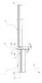
- the first light guide 51, the second light guide 52, and the lens member 53 are fixed to the inside of the first light guide rod 74 via the first ferrule 77, the second ferrule 78, and the spacer 79.
- the lens As a result, the lens member 53 is arranged between the first light guide 51 and the second light guide 52. Further, since the first light guide 51, the second light guide 52, and the lens member 53 are held at the centers of the first ferrule 77, the second ferrule 78, and the spacer 79, respectively, the central axis LLG of the light guide rod 65. And the central axes of the first light guide 51, the second light guide 52, and the lens member 53 coincide with each other.
- the lens member 53 is a plano-convex lens in which the lens surface 53A on the incident side is planar and the lens surface 53B on the exit side is convex.
- the lens member 53 may be a biconvex lens, a meniscus lens, or the like.
- the lens member 53 preferably has an antireflection film called an AR (anti-reflective coating) coating formed on the lens surfaces 53A and 53B. This makes it possible to further prevent a decrease in the amount of illumination light in the light guide unit 26.
- FIG. 10 shows the positional relationship between the first light guide 51, the second light guide 52, and the lens member 53 constituting the light guide unit 26, and the first light guide is to prevent the drawing from being complicated. The covering of the 51 and the second light guide 52 is omitted.
- the position of the lens member 53 in the axial direction is restricted because the lens surface 53A abuts on the edge of the through hole 79A and the lens surface 53B is pressed by the O-ring 83.
- the lens surfaces 53A and 53B of the lens member 53 are arranged at intervals from the exit end 51B of the first light guide 51 and the incident end 52A of the second light guide 52.
- the lens surface 53A has a gap D1 with respect to the emission end 51B of the first light guide 51.
- the gap D1 is preferably larger than 0 mm and preferably 0.5 mm or less.
- the lens surface 53B has a gap D2 with respect to the incident end 52A of the second light guide 52.
- the gap D2 is preferably larger than 0 mm and preferably 0.5 mm or less.
- the light guide portion 26 in the present embodiment has a circular end surface at the incident end 51A of the first light guide 51 facing the light source portion 42, but as shown in FIG.
- the emission end 28 of the second light guide 52 in the tip portion 21A is formed in an arc shape located around the observation portion 27 for the convenience of arranging the parts of the tip portion 21A. Therefore, it is difficult to arrange the lens member 53 on the tip portion 21A.
- the inside of the light guide rod 65 is easy to arrange because there is no component that hinders the arrangement of the lens member 53.
- the first light guide 51 and the lens member 53 are arranged so that the light emitting point of the first light guide 51 is closer to the lens surface 53A than the focal point P on the incident side of the lens member 53.
- the illumination light emitted from the light emitting point of the first light guide 51 travels in a diffused direction when passing through the lens member 53. Therefore, the light guide unit 26 using the lens member 53 can obtain the effects of preventing a decrease in the amount of light and preventing deterioration of the light distribution.
- the first light guide 51 forms a light emitting point at the emission end 51B. Therefore, it is preferable that the first light guide 51 has a dimension L1 of 5 mm or more in the axial direction from the incident end 51A to the emitted end 51B.
- the lens member 53 is a lens guided by the first light guide 51 and the second light guide 52 to prevent a decrease in the amount of light and a deterioration in the light distribution of the illumination light emitted from the emission end 28.
- the lens member 53 is guided by the first light guide 51 and the second light guide 52, and suppresses variations in the relative intensity of each color of the illumination light emitted from the emission end 28 with respect to the light distribution angle. It is a lens.
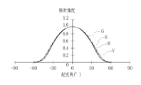
- the graphs shown in FIGS. 13 and 14 show the positions of the light guide portion 26 before the illumination light passes through the lens member 53 (FIG. 13) and the positions after the illumination light passes through the lens member 53 (FIG. 14).
- the relative intensity referred to here is expressed as a ratio of the light intensity of each color of LED light when the light distribution angle is 0 ° to 1 and the light intensity other than the light distribution angle of 0 ° to the light intensity at 0 °. It was done.
- the light intensity is the density within the unit solid angle of the luminous flux of light.
- the light source unit 42 emits light and the light guide unit 26 guides the LED light.
- the purple light V, the blue light B, the green light G, and the red light R have variations in relative intensity with respect to the light distribution angle. In particular, there is a large variation in relative intensity when the light distribution angle is around ⁇ 25 °.
- the light source unit 42 emits light and the light guide unit 26 guides the light.
- the purple light V, the blue light B, the green light G, and the red light R which are the LED lights, have the same relative intensities with respect to the light distribution angle. That is, it is possible to suppress variations in relative strength.
- the fact that the relative intensities match here means that the difference in the relative intensities of each color with respect to the light distribution angle is very small, and when the relative intensities of the green light G are used as a reference, the purple light V and the blue light B are used.
- the relative intensities of the red light R are all within ⁇ 5% of the relative intensities of the green light G.
- the light guide unit 26 is composed of the first light guide 51, the second light guide 52, and the lens member 53, and the first light guide 51, the second light guide 52, and the lens member. 53 is fixed to the inside of the first light guide rod 74 having rigidity. Therefore, the positions of the optical axes of the first light guide 51, the second light guide 52, and the lens member 53 do not shift. Therefore, regardless of the operating state of the endoscope 12, the light guide unit 26 can prevent a decrease in the amount of illumination light and a deterioration in the light distribution by the lens member 53.
- the endoscope 12 needs to be sterilized each time it is used. In this case, it is common to perform sterilization using an autoclave. During this sterilization process, the connector 25 including the light guide rod 65 is exposed to saturated steam at high temperature and high pressure (for example, 135 ° C., 5 atm) for about 20 minutes.
- high temperature and high pressure for example, 135 ° C., 5 atm
- the lens member 53 is in contact with the first light guide 51 and the second light guide 52, when the sterilization process by the autoclave is repeatedly performed, the coefficient of thermal expansion of the lens member 53 and the first light guide 51 and Due to the difference from the coefficient of thermal expansion of the second light guide 52, the lens member 53 may be scratched by being pressed by the first light guide 51 and the second light guide 52.
- the lens member 53 since the lens member 53 has gaps D1 and D2 with respect to the end faces of the first light guide 51 and the second light guide 52, the lens member 53 is sterilized even if the endoscope 12 is sterilized.
- the first light guide 51 and the second light guide 52 do not come into contact with each other, and the lens member 53 is not scratched.
- the adhesive used for fixing the first light guide 51 and the second light guide 52 does not adhere to the lens member 53.
- the lens member 53 for reducing the amount of light and deteriorating the light distribution is arranged inside the light guide rod 65
- the present invention is not limited to this, and the light guide rod 65 is excluded. It may be arranged inside the connector 25.
- the lens member 53 is arranged inside the outer case 91 constituting the connector 90.
- the configurations other than the connector 90 are the same as those of the endoscope system 10 of the first embodiment, and the same parts and the like are designated by the same reference numerals and the description thereof will be omitted.
- the connector 90 is provided at the base end of the universal cable 23 and is detachably connected to the light source device side connector 41 of the light source device 14.
- the connector 90 includes an exterior case 91, a light guide rod 92, and a lens member holding portion 93.
- the exterior case 91 houses the wireless communication unit 63, the wireless power receiving unit 64, and the like in the exterior case 61 of the connector 25 of the first embodiment, and is a light guide rod from the front surface 61A located on the light source device 14 side. 92 is protruding.
- the light guide rod 92 holds only the first light guide 51, and does not hold the second light guide 52 and the lens member 53.
- the lens member holding portion 93 is the same as the first light guide rod 74 of the first embodiment, via the first ferrule 77, the second ferrule 78, and the spacer 79, and the first light guide 51 and the second light guide 52. , And the lens member 53 are fixed inside. As a result, the lens member 53 is arranged between the first light guide 51 and the second light guide 52. Further, as in the first embodiment, the incident end 51A of the first ride guide 51 faces the light source portion 42, and the exit end 28 of the second light guide 52 is located at the tip portion 21A. Therefore, the light guide unit 26 guides the illumination light generated by the light source unit 42 to the tip portion 21A of the endoscope 12.
- an O-ring 83 is housed inside the spacer 79, and the O-ring 83 is sandwiched between the lens member 53 and the second light guide 52 as in the first embodiment. Therefore, the lens member 53 and the second light guide 52 are arranged at a distance from each other.
- the lens member holding portion 93 is fixed to the inside of the outer case 91.
- the outer case 91 and the lens member holding portion 93 are made of, for example, resin parts and have high rigidity. Further, an O-ring or the like (not shown) is provided in the gap between the parts constituting the outer case 91 to ensure airtightness. Therefore, the lens member holding portion 93 does not require a structure for ensuring airtightness. That is, unlike the first light guide rod 74 of the first embodiment, it is not necessary to provide O-rings 81, 82, 84 and the like for ensuring airtightness, and the number of parts can be reduced.
- the light guide unit 26 can prevent a decrease in the amount of illumination light and a deterioration in the light distribution by the lens member 53 regardless of the operating state of the endoscope.
- the present invention is not limited to this, and the endoscope is not limited to this. May be configured and placed inside other rigid components.
- the operation unit 102 connected to the insertion unit 101 is provided, and the lens member 53 is arranged inside the operation unit 102.
- the configurations other than the endoscope 100 are the same as those of the endoscope system 10 of the first embodiment, and the same parts and the like are designated by the same reference numerals and the description thereof will be omitted.
- the endoscope 100 is a rigid endoscope such as a laparoscope, and has an elongated rigid insertion portion 101 inserted into a subject and an insertion portion 101. It is provided with an operation unit 102 connected to the base end portion of the above and a flexible universal cable 23 connected to the operation unit 102.
- a connector 103 is provided at the base end of the universal cable 23, and the endoscope 100 is detachably connected to the light source device side connector 41 of the light source device 14 via the connector 103. Note that, unlike the connectors 25 and 90 of the first and second embodiments, the connector 103 holds only the first light guide 51, and does not hold the second light guide 52 and the lens member 53.
- the insertion portion 101 has a tip portion 101A and a curved portion 101B.
- the tip portion 101A is provided with an observation portion 27 and an emission end 28, similarly to the tip portion 21A of the endoscope 12 of the first embodiment.
- the curved portion 101B is continuously provided at the tip portion 101A and is provided so as to be bendable.
- the operation unit 102 is provided with a bending operation lever 102A, an operation button (not shown), and the like.
- the bending operation lever 102A is an operation member for bending the bending portion 101B. By bending the curved portion 101B, the direction of the tip portion 101A can be changed.
- the operation unit 102 is composed of, for example, resin parts and has high rigidity. It is preferable that the lens member 53 is provided inside the endoscope 100 at a position other than the curved portion 101B. More specifically, the lens member 53 is provided inside the operation unit 102. Similar to the lens member holding portion 93 in the second embodiment, the operating portion 102 has a holding portion (not shown) in which the first light guide 51, the second light guide 52, and the lens member 53 are fixed internally. Are provided integrally.
- the lens member 53 is provided on the curved portion 101B, if the curved portion 101B is curved, the positions of the optical axes of the first light guide 51, the second light guide 52, and the lens member 53 are displaced.
- the lens member 53 is provided inside the operation unit 102. Since the operation unit 102 has rigidity, the positions of the optical axes of the first light guide 51, the second light guide 52, and the lens member 53 do not shift. Therefore, as in the first embodiment, the light guide unit 26 can prevent a decrease in the amount of illumination light and a deterioration in the light distribution by the lens member 53 regardless of the operating state of the endoscope.
- an endoscope used as a laparoscope has been described as an example, but the present invention may be applied to an endoscope used for other purposes such as industrial use. can.
Landscapes
- Health & Medical Sciences (AREA)
- Life Sciences & Earth Sciences (AREA)
- Surgery (AREA)
- Physics & Mathematics (AREA)
- Engineering & Computer Science (AREA)
- Optics & Photonics (AREA)
- Biomedical Technology (AREA)
- General Health & Medical Sciences (AREA)
- Pathology (AREA)
- Nuclear Medicine, Radiotherapy & Molecular Imaging (AREA)
- Biophysics (AREA)
- Heart & Thoracic Surgery (AREA)
- Medical Informatics (AREA)
- Molecular Biology (AREA)
- Animal Behavior & Ethology (AREA)
- Radiology & Medical Imaging (AREA)
- Public Health (AREA)
- Veterinary Medicine (AREA)
- Computer Networks & Wireless Communication (AREA)
- Astronomy & Astrophysics (AREA)
- General Physics & Mathematics (AREA)
- Endoscopes (AREA)
- Instruments For Viewing The Inside Of Hollow Bodies (AREA)
Abstract
内視鏡の動作状態に関わらず、照明光の光量低下及び配光劣化を防ぐことができる内視鏡システムを提供する。 内視鏡(12)は、挿入部(21)、コネクタ(25)、及び導光部(26)を有する。光源装置(14)は光源部(42)を有する。導光部(26)は、内視鏡(12)が光源装置(14)に接続された場合、光源部(42)からの照明光を挿入部(21)の先端部(21A)に導光するライトガイド(51、52)と、先端部(21A)から出射される照明光の、配光角に対する各色の相対強度のばらつきを抑制するレンズ部材(53)とを含む。レンズ部材(53)は、剛性を有するコネクタ(25)の内部に設けられている。
Description
本発明は、内視鏡システムに関する。
内視鏡は、医療分野及び工業用分野において広く利用されている。内視鏡は、被検体内に挿入する挿入部を有し、挿入部の先端部から照明光を観察対象に照射する。内視鏡の内部には、光源装置から供給された照明光を挿入部の先端部に導光する導光部を備えている。導光部が照明光を導光し、観察対象を照明することにより被検体内を観察することができる。
特許文献1記載の内視鏡では、導光部は、複数のライトガイドを備えている。ライトガイドは、例えば、石英系ファイバ又は多成分系ファイバを束ねたファイバ束から構成される。このようなファイバ束のうち、石英系ファイバから構成されるものは、可撓性に優れているが、光の減衰率が高い。そこで、特許文献1記載の内視鏡では、複数のライトガイドの間にレンズを配置している。このレンズを用いることにより、光量低下及び配光劣化を防止し、光源側のライトガイドの端部からの光を先端部側のライトガイドの端部に伝送する。
一方、内視鏡においては、観察部位を様々な角度で観察したり、挿入を容易にするために、挿入部の先端に湾曲可能な湾曲部が設けられているものがある。上記特許文献1記載の内視鏡では、湾曲部の内部にライトガイドの端部及びレンズを配している。
しかしながら、上記特許文献1記載の内視鏡では、ライトガイドの端部及びレンズを湾曲部の内部に配置しているため、光軸ずれが発生する可能性がある。すなわち、湾曲部が湾曲している場合、レンズと対面する光源側及び先端部側のライトガイドの端部の中心軸と、光量低下及び配光劣化防止用のレンズの中心軸とが一致しなくなるため、光量低下及び配光劣化などの性能低下が発生する可能性が高い。
本発明は、内視鏡の動作状態に関わらず、照明光の光量低下及び配光劣化を防ぐことができる内視鏡システムを提供することを目的とする。
本発明の内視鏡システムは、挿入部、照明光出射端、及び導光部を有する内視鏡と、光源装置とを備えた内視鏡システムであって、導光部は、ライトガイドと、光学部材とを含み、光学部材は、内視鏡の内部であって、照明光出射端よりも基端側、且つ剛性を有する箇所に設けられている。挿入部は、被検体内に挿入される。照明光出射端は、挿入部の先端部に設けられている。導光部は、照明光を導光する。光源装置は、内視鏡と接続され、互いに異なる色光を発する複数の光源を有し、光源により複数の色光を混合した照明光を発する。ライトガイドは、内視鏡が光源装置に接続された場合、光源からの照明光を照明光出射端に導光する。光学部材は、ライトガイドにより導光され、照明光出射端から出射される照明光の、配光角に対する各色の相対強度のばらつきを抑制する。
導光部は、複数のライトガイドを有し、光学部材は、複数のライトガイドの間に配されているレンズ部材であることが好ましい。
ライトガイド及びレンズ部材は、ライトガイドにより導光される照明光の発光点が、レンズ部材の入射側における焦点よりもレンズ部材と近接する位置に配されていることが好ましい。
レンズ部材のレンズ面は、ライトガイドの出射端及び入射端に対して間隔を置いて配されることが好ましい。
内視鏡は、光源装置と接続するコネクタを有し、光学部材は、コネクタの内部に配されていることが好ましい。コネクタは、光源装置と接続した場合、光源装置の内部に挿入されるライトガイド棒を有し、光学部材は、ライトガイド棒の内部に配されていることがさらに好ましい。
挿入部は、先端部の向きを変える湾曲部を有し、光学部材は、内視鏡の内部であって、湾曲部を除く箇所に設けられていることが好ましい。
内視鏡は、挿入部と連設された操作部を備えており、光学部材は、操作部に設けられていることが好ましい。
複数のライトガイドのうち、光学部材の入射側に位置するライトガイドは、光軸方向における入射端から出射端までの寸法が5mm以上であることが好ましい。レンズ部材は、レンズ面に反射防止膜が形成されていることが好ましい。
レンズ部材は、光源が発する複数の色光のうち、1つの色光の相対強度を基準とした場合、他の色光の相対強度を、基準とした色光の相対強度と±5%以内の差にすることが好ましい。
本発明の内視鏡システムによれば、内視鏡の動作状態に関わらず、照明光の光量低下及び配光劣化を防ぐことができる
[第1実施形態]
[内視鏡システムの概略構成]
図1に示すように、内視鏡システム10は、内視鏡12と、光源装置14と、プロセッサ装置16と、モニタ18と、コンソール20と、を有する。内視鏡12は、例えば腹腔鏡等の硬性内視鏡であり、被検体内に挿入される細長い硬性の挿入部21と、挿入部21の基端部に連設されたL字形状のグリップ部22と、グリップ部22を介して挿入部21に基端部が接続された軟性のユニバーサルケーブル23と、ユニバーサルケーブル23の中途部分に設けられたスイッチ配置部材24と、を備える。
[内視鏡システムの概略構成]
図1に示すように、内視鏡システム10は、内視鏡12と、光源装置14と、プロセッサ装置16と、モニタ18と、コンソール20と、を有する。内視鏡12は、例えば腹腔鏡等の硬性内視鏡であり、被検体内に挿入される細長い硬性の挿入部21と、挿入部21の基端部に連設されたL字形状のグリップ部22と、グリップ部22を介して挿入部21に基端部が接続された軟性のユニバーサルケーブル23と、ユニバーサルケーブル23の中途部分に設けられたスイッチ配置部材24と、を備える。
ユニバーサルケーブル23の基端部には、コネクタ25が設けられており、内視鏡12はコネクタ25を介して光源装置14の光源装置側コネクタ41に着脱自在に接続される。ユニバーサルケーブル23は、光源装置14が発する照明光を導光する導光部26(図2参照)や、挿入部21の先端部21Aに設けられた撮像センサ33を制御する制御線、照明光が照射された観察対象を撮像したときに撮像センサ33が出力する画像信号を送信する信号線、撮像センサ等の各部に電力を供給する電力線等が一体になったケーブルである。なお、図2においては、図面の煩雑化の都合上、制御線、信号線、及び電力線は省略している。
本実施形態の内視鏡システム10では、内視鏡12と光源装置14との間で、コネクタ25と光源装置側コネクタ41とを介して、電力及び光信号等を非接触で伝送する構成を備えている。また、前述のスイッチ配置部材24に配置される操作スイッチ24Aとしては、例えば、モニタ18に表示される画像を、通常の撮像画像と特殊光の画像(例えば、WL(whiteLight)画像、BLI(BLueLASERImaging)画像、LCI(LinkedCoLorImaging)画像又は低酸素イメージング画像)とを切り替える画像切替スイッチを適用することができる。また、これに限らず、画像静止スイッチ、撮影スイッチ、テレとワイドのボタンを備えたズームスイッチ、挿入部先端部の洗浄スイッチ、ライト光量調整スイッチ、又は感度調整スイッチ等を適用することもできる。
[内視鏡の概略構成]
図2に示すように、挿入部21の先端部21Aには、観察部27と、照明光出射端(以下、単に出射端とする。)28とが設けられている。観察部27は、観察窓29と、観察窓29の背部に配置された撮像レンズ群31及びプリズム32と、撮像センサ33とを備えている。
図2に示すように、挿入部21の先端部21Aには、観察部27と、照明光出射端(以下、単に出射端とする。)28とが設けられている。観察部27は、観察窓29と、観察窓29の背部に配置された撮像レンズ群31及びプリズム32と、撮像センサ33とを備えている。
撮像センサ33は、例えば原色系のカラーフィルタを有するカラーセンサであり、青色カラーフィルタを有するB画素(青色画素)、緑色カラーフィルタを有するG画素(緑色画素)、及び、赤色カラーフィルタを有するR画素(赤色画素)の3種類の画素を備える。青色カラーフィルタは、主として紫色から青色の光を透過する。緑色カラーフィルタは、主として緑色の光を透過する。赤色カラーフィルタは、主として赤色の光を透過する。上記のように原色系の撮像センサ33を用いて観察対象を撮像すると、最大で、B画素から得るB画像(青色画像)、G画素から得るG画像(緑色画像)、及び、R画素から得るR画像(赤色画像)の3種類の画像を同時に得ることができる。
なお、撮像センサ33としては、CCD(Charge Coupled Device)型イメージセンサ又はCMOS(Complementary Metal Oxide Semiconductor)イメージセンサを適用することができる。また、本実施形態の撮像センサ33は、原色系のカラーセンサであるが、補色系のカラーセンサを用いることもできる。補色系のカラーセンサは、例えば、シアンカラーフィルタが設けられたシアン画素、マゼンタカラーフィルタが設けられたマゼンタ画素、イエローカラーフィルタが設けられたイエロー画素、及び、グリーンカラーフィルタが設けられたグリーン画素を有する。補色系カラーセンサを用いる場合に上記各色の画素から得る画像は、補色-原色色変換をすれば、B画像、G画像、及びR画像に変換できる。また、カラーセンサの代わりに、カラーフィルタを設けていないモノクロセンサを撮像センサ33として使用してもよい。この場合、BGR等各色の照明光を用いて観察対象を順次撮像することにより、上記各色の画像を得ることができる。
[プロセッサ装置の概略構成]
プロセッサ装置16は、光源装置14が発する照明光の光量や発光タイミング、撮像センサ33の動作等を制御し、照明光が照射された観察対象を撮像して得る画像信号を用いて内視鏡画像を生成する。また、プロセッサ装置16は、モニタ18及びコンソール20と電気的に接続する。モニタ18は、プロセッサ装置16が生成した内視鏡画像や、内視鏡画像に関する情報等を表示する。コンソール20は、機能設定等の入力操作を受け付けるユーザインターフェースである。
プロセッサ装置16は、光源装置14が発する照明光の光量や発光タイミング、撮像センサ33の動作等を制御し、照明光が照射された観察対象を撮像して得る画像信号を用いて内視鏡画像を生成する。また、プロセッサ装置16は、モニタ18及びコンソール20と電気的に接続する。モニタ18は、プロセッサ装置16が生成した内視鏡画像や、内視鏡画像に関する情報等を表示する。コンソール20は、機能設定等の入力操作を受け付けるユーザインターフェースである。
[光源装置の概略構成]
図2に示すように、光源装置14は、光源部42と、光源制御部43と、無線通信部44と、無線給電部45とを備えている。光源部42は、観察対象の照明に用いる照明光を発する。光源制御部43は、光源部42を制御する。なお、図示は省略するが、光源装置14は、プロセッサ装置16と、制御信号及び画像信号等の伝送を行う信号伝送部を備えている。
図2に示すように、光源装置14は、光源部42と、光源制御部43と、無線通信部44と、無線給電部45とを備えている。光源部42は、観察対象の照明に用いる照明光を発する。光源制御部43は、光源部42を制御する。なお、図示は省略するが、光源装置14は、プロセッサ装置16と、制御信号及び画像信号等の伝送を行う信号伝送部を備えている。
光源部42は、複数色のLED(Light Emitting Diode)の半導体光源である。光源制御部43は、LEDのオン/オフや、LEDの駆動電流や駆動電圧の調整によって、照明光の発光量を制御する。なお、光源部42を構成する半導体光源としては、LEDに限らず、LD(Laser Diode)等でもよい。
光源部42は、V-LED(Violet Light Emitting Diode)42a、B-LED(Blue Light Emitting Diode)42b、G-LED(Green Light Emitting Diode)42c、及びR-LED(Red Light Emitting Diode)42dの4色のLEDとを有している。
LED42a~42dは、互いに異なる色光を発する。例えば、V-LED42aは、波長帯域380nm~420nmの紫色光Vを発する。B-LED42bは、波長帯域420nm~500nmの青色光Bを発する。G-LED42cは、波長帯域が480nm~600nmに及ぶ緑色光Gを発する。R-LED42dは、波長帯域が600nm~650nmに及び赤色光Rを発する。なお、各LED42a~42dから発せられる光は、それぞれの中心波長とピーク波長とが同じであっても良いし、異なっていても良い。
光源制御部43は、各LED42a~42dの点灯や消灯、及び点灯時の発光量等を独立に制御することによって、照明光の発光タイミング、発光期間、光量、及び分光スペクトルの調節を行う。光源制御部43における点灯及び消灯の制御は、観察モードごとに異なっている。なお、基準の明るさはコンソール20等によって設定可能である。
通常モードの場合、光源制御部43は、V-LED42a、B-LED42b、G-LED42c、及びR-LED42dを全て点灯させる。これにより、通常モードでは、光源装置14から、紫色光、青色光、緑色光、及び赤色光を含む通常モード用の多色光が、通常光として発せられる。通常光は、紫色光、青色光、緑色光、及び赤色光を混合しており、青色帯域から赤色帯域まで一定以上の強度を有しているため、ほぼ白色の白色光である。なお、白色光は、キセノンランプが発する白色光のように、青色成分、緑色成分、赤色成分の波長帯域をすべて含む広帯域光だけでなく、青色成分、緑色成分、赤色成分の少なくとも3色のそれぞれの波長帯域の光を混合した照明光も含む。
特殊モードの場合、光源制御部43は、V-LED42a、B-LED42b、G-LED42c、及びR-LED42dを全て点灯させるが、その際、紫色光が占める割合を大きくするように、紫色光、青色光、緑色光、及び赤色光間の光量比を設定する。これにより、特殊光は、青みを帯びた光となっている。なお、以下では、照明光として白色光を発する通常モードの場合を主に説明する。
また、光源装置14はプロセッサ装置16と電気的に接続しており、内視鏡12のコネクタ25は光源装置14を介してプロセッサ装置16と接続する。光源装置14とコネクタ25の画像信号等の送受信は無線通信である。このため、光源装置14は、無線でコネクタ25と送受信した画像信号等をプロセッサ装置16に伝送する。さらに、光源装置14はコネクタ25に撮像センサ33等を駆動するための電力を供給するが、この電力の供給も無線で行う。
図3に示すように、光源装置側コネクタ41は、係止部41A、41Bと、当接面41Cと、嵌合凹部41Dと、接続孔41Eとが設けられている。当接面41Cは、後述するコネクタ25の前面61Aと当接する平坦面である。係止部41A、41Bは、当接面41Cに対して突出した位置にあり、コネクタ25が接続された場合、コネクタ25を係止して接続を維持する。嵌合凹部41Dは、当接面41Cよりも一段凹となる凹部であり、後述するコネクタ25の嵌合凸部61Bが嵌合する。接続孔41Eは、嵌合凹部41Dの内部に設けられた貫通孔であり、コネクタ25のライトガイド棒65が挿し込まれる。
コネクタ25を光源装置側コネクタ41に接続する場合、ライトガイド棒65を光源装置側コネクタ41の接続孔41Eに挿入することにより、第1ライトガイド51の入射端51Aが光源装置14の光源部42に対面する。これにより、光源部42からの照明光が第1ライトガイド51、及びレンズ部材53を介して伝送されて、第2ライトガイド52の出射端28から挿入部21の前方に照射される。
また、当接面41Cの下部の背後には、コネクタ25の無線通信部63と無線で通信をする無線通信部44と、コネクタ25の無線受電部64に電力を供給する無線給電部45とが設けられている。無線通信部44は、画像信号受信部46(図2参照)を含む。画像信号受信部46は、コネクタ25の画像信号送信部66から画像信号を受信する。無線通信部44の接続孔44Aは、コネクタ25の接続ピン63Aを挿入する形状の孔部になっている。無線給電部45は、例えばコイル(いわゆる1次コイル)であり、電磁誘導方式や磁界共鳴方式等の非接触電力伝送方式で無線受電部64に電力を供給する。
内視鏡12のコネクタ25を、光源装置14の光源装置側コネクタ41に接続した場合、光源部42が発光した照明光は、例えば、プリズム、導光ロッド等の導光部材(図示せず)により、内視鏡12の導光部26に入射する。
導光部26は、ユニバーサルケーブル23及びコネクタ25を含む内視鏡12内に内蔵されており、照明光を内視鏡12の先端部21Aまで導光する。先端部21Aには、出射端28が設けられている。出射端28は、観察窓29の周囲に配置され、後述する第2ライトガイド52の先端である。本実施形態では、観察窓29及び出射端28は、先端部21Aの先端面から露呈している。光源部42が発光した照明光は、導光部26によって光源部42から導光され、出射端28から観察対象に照射される。
導光部26は、第1ライトガイド51と、第2ライトガイド52と、レンズ部材53とを有する。ライトガイド51、52としては、光ファイバをバンドルしたファイバ束である。レンズ部材53は、特許請求の範囲における光学部材に相当する。ライトガイド51、52を構成する光ファイバは、例えば、石英系ファイバ又は多成分系ファイバである。本実施形態では、第1ライトガイド51、第2ライトガイド52の一部、及びレンズ部材53は、コネクタ25の内部であり、さらに詳しくはライトガイド棒65(図7参照)の内部に設けられている。なお、ライトガイド棒65の構造については後述する。
[コネクタの概略構成]
図4に示すように、コネクタ25は、外装ケース61と、シールドケース62(図6参照)と、無線通信部63と、無線受電部64と、ライトガイド棒65とを有する。以下、コネクタ25を光源装置14に正しく接続する姿勢を「接続姿勢」とし、接続姿勢でコネクタ25を光源装置14に接続する接続方向をZ方向とし、接続姿勢のコネクタ25の鉛直方向をY方向とし、かつ、Z方向及びY方向に垂直な水平面内方向をX方向とする。Z方向の正側はコネクタ25から見て光源装置14が位置する側とし、Y方向の正側は鉛直上方とし、かつ、X方向の正側はZ方向の負側から正側に見て左方向とする。なお、以下では、コネクタ25の接続方向であるZ方向の正側を基端側、基端部、Z方向の負側を先端側、先端部という場合がある。
図4に示すように、コネクタ25は、外装ケース61と、シールドケース62(図6参照)と、無線通信部63と、無線受電部64と、ライトガイド棒65とを有する。以下、コネクタ25を光源装置14に正しく接続する姿勢を「接続姿勢」とし、接続姿勢でコネクタ25を光源装置14に接続する接続方向をZ方向とし、接続姿勢のコネクタ25の鉛直方向をY方向とし、かつ、Z方向及びY方向に垂直な水平面内方向をX方向とする。Z方向の正側はコネクタ25から見て光源装置14が位置する側とし、Y方向の正側は鉛直上方とし、かつ、X方向の正側はZ方向の負側から正側に見て左方向とする。なお、以下では、コネクタ25の接続方向であるZ方向の正側を基端側、基端部、Z方向の負側を先端側、先端部という場合がある。
外装ケース61は、無線通信部63及び無線受電部64を収納し、接続姿勢において光源装置14側に位置する前面61Aからライトガイド棒65が突出している。無線通信部63は、光源装置14と無線通信を行う。無線受電部64は、光源装置14から無線で電力の供給を受ける。ライトガイド棒65が突出する位置は、接続姿勢において鉛直上方に位置する側であるため、外装ケース61は、接続姿勢において鉛直下方に位置する側に、無線通信部63及び無線受電部64を収納する。
ライトガイド棒65の基端部分には、光源装置側コネクタ41の嵌合凹部41Dと嵌合する嵌合凸部61Bが設けられており、この嵌合凸部61Bは前面61Aから突出している。ライトガイド棒65の中心軸LLGは、Z方向に平行である。
図5に示すように、ライトガイド棒65は、前面61AのX方向における中央に配置されている。また、外装ケース61は、接続姿勢で鉛直上方に位置する上面61Cが曲面であり、かつ、接続姿勢で鉛直下方に位置する下面61Dが平面である。ライトガイド棒65は、前面61Aの上面61C側に設けられている。これに対し、無線通信部63及び無線受電部64は、前面61Aの下面61D側に左右に並んで収められている。
無線通信部63は、画像信号送信部66(図2参照)を含む。画像信号送信部66を構成する基板等の電子部品は、金属製のシールドケース62の内部に収納されている。画像信号送信部66は、照明光が照射された観察対象を撮像して得る画像信号を光源装置14の画像信号受信部46に無線で送信する。無線通信部63が行う無線通信は光通信であり、例えば近赤外光(波長がおよそ0.7μmから2.5μm程度の光)を用いた近赤外通信であることが好ましい。
無線通信部63は、接続ピン63Aを有する。接続ピン63Aは、先端部に光信号の出射端を有し、接続ピン63Aを光源装置側コネクタ41の接続孔44Aに接続することにより、光源装置14の無線通信部44と光信号の送受信が可能となる。これにより、画像信号送信部66の光信号は光源装置14の画像信号受信部46に非接触で光送信される。画像信号受信部46に光送信された画像信号は、プロセッサ装置16に送信される。内視鏡12から光源装置14を介してプロセッサ装置16に送信された画像信号は、画像処理が施されて内視鏡画像としてモニタ18に表示される。なお、光源装置14の無線通信部44、及びコネクタ25の無線通信部63の機能としては、上記のものに限らず、例えば、内視鏡12の撮像センサ33等を制御する制御信号を送受信してもよい。
無線受電部64は、例えばコイル(いわゆる2次コイル)であり、光源装置14に設け
られた無線給電部45から非接触電力伝送方式で電力の供給を受ける。無線受電部64は、シールドケース62に固着されている。なお、1次コイルと2次コイルとを利用して電力の給電を行う内視鏡は、特開2016-67534号公報により公知であるので、ここではその詳細な説明は省略する。図5に示すように、無線受電部64は、前面61Aの背後に設けられているため、前面61Aを通過して光源装置14から電力の供給を受ける。無線受電部64は、撮像センサ33等の内視鏡12の各部に電力を供給する。
られた無線給電部45から非接触電力伝送方式で電力の供給を受ける。無線受電部64は、シールドケース62に固着されている。なお、1次コイルと2次コイルとを利用して電力の給電を行う内視鏡は、特開2016-67534号公報により公知であるので、ここではその詳細な説明は省略する。図5に示すように、無線受電部64は、前面61Aの背後に設けられているため、前面61Aを通過して光源装置14から電力の供給を受ける。無線受電部64は、撮像センサ33等の内視鏡12の各部に電力を供給する。
コネクタ25が光源装置側コネクタ41に接続された場合、外装ケース61の上面61C及び下面61Dで係止することでコネクタ25を係止して接続を維持する。上述したように、光源装置側コネクタ41には、係止部41A、41Bが設けられている。これに対応して、コネクタ25の上面61Cには光源装置14の係止部41Aが嵌る溝61Eが設けられ、コネクタ25の下面61Dには光源装置14の係止部41Bが嵌る溝61Fが設けられている。
図6に示すように、外装ケース61は、ケース本体68と、ケース蓋69とを有し、ケース本体68の基端部にケース蓋69を結合させることにより、中空状に構成される。外装ケース61を構成するケース本体68及びケース蓋69は、耐熱性及び耐薬品性の高い樹脂製である。
ケース蓋69は、上述した前面61A及び嵌合凸部61Bが設けられており、上面61C及び下面61Dの一部を有する。ケース蓋69の後端部外周面には、封止部材であるOリング71が嵌合されている。このOリング71は、外装ケース61の内部を封止する複数の封止部材のうちの一つである。
嵌合凸部61Bの中央部にはライトガイド棒65を外部に導出する導出孔61Gが形成されている。ライトガイド棒65は、その基端部が外装ケース61の内部に配置されたブラケット72に固定されている。ブラケット72は、L字状に形成され、ケース本体68の内側に固着されている。ブラケット72がケース蓋69の内周面69A(図7参照)に固定されることにより、ライトガイド棒65がケース本体68及びケース蓋69に支持されている。
ライトガイド棒65の外周面には、弾性を有するOリング73が嵌合されており、ライトガイド棒65は、Oリング73を介して導出孔61Gに嵌合される。このOリング73もOリング71と同様に、外装ケース61の内部を封止する複数の封止部材のうちの一つである。
[ライトガイド棒の概略構成]
図7に示すように、ライトガイド棒65は、第1ライトガイド棒74と、第2ライトガイド棒75とを備える。第1ライトガイド棒74及び第2ライトガイド棒75は、剛性の高い金属などにより円筒形状に形成されている。第1ライトガイド棒74は、入射窓76、第1ライトガイド51、第2ライトガイド52、及びレンズ部材53を内側に収納する。入射窓76は、透明なカバーガラスであり、第1ライトガイド棒74の基端部に固着されている。この入射窓76を介して、光源部42からの照明光が通過し、第1ライトガイド51に照明光が入射する。第1ライトガイド棒74の基端部内周面には、弾性を有するOリング81が嵌合されている。Oリング81が入射窓76と第1ライトガイド棒74との間で変形し、両者に密着することで、第1ライトガイド棒74の基端部における気密性が確保される。
図7に示すように、ライトガイド棒65は、第1ライトガイド棒74と、第2ライトガイド棒75とを備える。第1ライトガイド棒74及び第2ライトガイド棒75は、剛性の高い金属などにより円筒形状に形成されている。第1ライトガイド棒74は、入射窓76、第1ライトガイド51、第2ライトガイド52、及びレンズ部材53を内側に収納する。入射窓76は、透明なカバーガラスであり、第1ライトガイド棒74の基端部に固着されている。この入射窓76を介して、光源部42からの照明光が通過し、第1ライトガイド51に照明光が入射する。第1ライトガイド棒74の基端部内周面には、弾性を有するOリング81が嵌合されている。Oリング81が入射窓76と第1ライトガイド棒74との間で変形し、両者に密着することで、第1ライトガイド棒74の基端部における気密性が確保される。
第1ライトガイド51は、第1フェルール(ferrule)77によって、第2ライトガイド52は、第2フェルール78によって、レンズ部材53は、スペーサ79によってそれぞれ保持された状態で、第1ライトガイド棒74の内部に固定されている。
図8に示すように、第1フェルール77は、中心に軸方向に沿って貫通したライトガイド挿入孔77Aが設けられた円筒形状をしている。ライトガイド挿入孔77Aには、第1ライトガイド51が挿入されている。第1ライトガイド51は、例えば、接着剤等によって接着されてライトガイド挿入孔77Aに固定されている。第1フェルール77の外周面には、弾性を有するOリング82が嵌合されている。
第1フェルール77は、第1ライトガイド51及びOリング82とともに、第1ライトガイド棒74の先端側から入射窓76と近接する位置まで挿入され、第1ライトガイド棒74の内周面に嵌合される。これにより、第1フェルール77とともに、第1ライトガイド51が第1ライトガイド棒74に固定される。また、Oリング82が第1フェルール77と第1ライトガイド棒74との間で変形し、両者に密着することで、第1フェルール77と第1ライトガイド棒74との間の気密性が確保される。
第2フェルール78は、中心に軸方向に沿って貫通したライトガイド挿入孔78Aが設けられた円筒形状をしている。ライトガイド挿入孔78Aには、第2ライトガイド52の基端部が挿入されている。第2ライトガイド52は、ライトガイド挿入孔78Aの先端側から突出し、第2ライトガイド棒75、コネクタ25、ユニバーサルケーブル23、グリップ部22及び挿入部21を通って、内視鏡12の先端部21Aに固定されている。
第2ライトガイド52の基端部は、例えば、接着剤等によって接着されてライトガイド挿入孔78Aに固定されている。第2フェルール78は、第1フェルール77と対面する基端面に開口部78Bが設けられている。開口部78Bは、ライトガイド挿入孔78Aよりも内径が大きく形成された円形状の開口部である。開口部78Bには、スペーサ79が嵌合される。また、開口部78Bには、係止溝78Cが形成されている。
第2フェルール78の外周面には、外径が一段大きく形成された大径部78Dと、大径部78Dよりも外径が小さい小径部78Eとを有する。大径部78Dは、第1ライトガイド棒74の内周面に嵌合される。これにより、第2フェルール78とともに、第2ライトガイド52の基端部が第1ライトガイド棒74に固定される。なお、第2ライトガイド52の基端は、ライトガイド挿入孔78Aの基端側から開口部78Bの内部に突出している。また、小径部78Eは、第1ライトガイド棒74の内周面との間に隙間を有している。
図9に示すように、スペーサ79は、中心に軸方向に沿って貫通した貫通孔79Aが設けられた円板形状をしている。スペーサ79は、貫通孔79Aの先端側に、レンズ部材保持部79B、Oリング収納部79Cを有する。レンズ部材保持部79Bは、貫通孔79Aよりも一回り大きい開口部であり、内径がレンズ部材53の外径に合わせて形成されている。レンズ部材保持部79Bは、レンズ部材53の外周面が嵌合することによりレンズ部材53を保持する。
Oリング収納部79Cは、レンズ部材保持部79Bよりも内径が一回り大きく形成された開口部である。Oリング収納部79Cは、内部に弾性を有するOリング83を収納する。なお、Oリング83の内径は、レンズ部材53の外径、及び第2ライトガイド52の基端部における外径よりも小さい。
スペーサ79は、外周面79Dに被係止部79Eが形成されている。被係止部79Eは、外周面79Dに沿った円環状の突起部でもよく、外周面79Dから突出する複数の突起部でもよい。被係止部79Eは、開口部78Bの係止溝78Cに係止される。スペーサ79の外周面79Dは、開口部78Bの内周面に合わせて形成されている。
スペーサ79は、レンズ部材保持部79Bにレンズ部材53を保持するとともに、Oリング収納部79CにOリング83を収納した状態で、第2フェルール78の開口部78Bに固定されている。外周面79Dが開口部78Bの内周面に嵌合するとともに、被係止部79Eが係止溝78Cに係止される。これにより、スペーサ79は開口部78Bに対する位置が規制されているため、開口部78Bから離脱することがない。
上述したように、第2ライトガイド52の基端は、開口部78Bの内部に突出している。このため、スペーサ79が第2フェルール78の開口部78Bに固定された場合、第2ライトガイド52の基端は、スペーサ79の内部に突出してOリング83を基端側に押圧する。レンズ部材53は、第2ライトガイド52からOリング83を介して受けた押圧によりスペーサ79の基端側に押し付けられる。
レンズ部材53は、スペーサ79を介して第2フェルール78に固定され、さらに、第2フェルール78が第1ライトガイド棒74に嵌合することにより、第1ライトガイド棒74に固定されている。レンズ部材53は、Oリング83により基端側に向かって押圧を受け、且つ貫通孔79Aの端縁に当接している。これにより、レンズ部材53は、スペーサ79に対して軸方向の位置が規制されている。
図8に示すように、第2ライトガイド棒75は、第1ライトガイド棒74の先端側に結合している。第2ライトガイド棒75は、基端部に嵌合部75Aを有する。嵌合部75Aは、第2ライトガイド棒75の最も外径が大きい部分の外周面よりも外径が小さく形成され、第1ライトガイド棒74の内周面に嵌合する。また、嵌合部75Aの最基端側の端部75Bは、厚みが小さく形成されており、第2フェルール78の小径部78Eと、第1ライトガイド棒74の内周面との間に形成された隙間に挿入される。
嵌合部75Aと第1ライトガイド棒74の内周面との嵌合により、第1ライトガイド棒74と第2ライトガイド棒75とが結合するとともに、第2フェルール78の位置が規制される。これにより、第2フェルール78が先端側へ離脱することがない。なお、第1ライトガイド棒74と第2ライトガイド棒75との結合はこれに限らず、接着剤又は接続部材を用いるなど、両者を接続できる構成であればよい。
また、嵌合部75Aには、弾性を有するOリング84が嵌合されている。Oリング84が第1ライトガイド棒74の内周面と嵌合部75Aとの間で変形し、両者に密着することで、第1ライトガイド棒74と第2ライトガイド棒75との間の気密性が確保される。以上のように、第1ライトガイド棒74及び第2ライトガイド棒75に、Oリング81、82、84などを取り付けることにより、内視鏡12がオートクレーブによる滅菌処理を行う際、高温及び高圧の飽和水蒸気が第1ライトガイド棒74及び第2ライトガイド棒75の内部に進入することを防止する。
上述したように、第1ライトガイド51、第2ライトガイド52、及びレンズ部材53は、第1フェルール77、第2フェルール78及びスペーサ79を介して、第1ライトガイド棒74の内部に固定される。これにより、レンズ部材53は、第1ライトガイド51と第2ライトガイド52との間に配される。また、第1ライトガイド51、第2ライトガイド52、及びレンズ部材53は、それぞれ第1フェルール77、第2フェルール78及びスペーサ79の中心に保持されているため、ライトガイド棒65の中心軸LLGと、第1ライトガイド51、第2ライトガイド52、及びレンズ部材53の中心軸が一致する。
図10に示すように、レンズ部材53は、入射側のレンズ面53Aが平面状で、出射側のレンズ面53Bが凸状の平凸レンズである。なお、これに限らず、レンズ部材53は、両凸レンズ、メニスカスレンズなどでもよい。レンズ部材53は、レンズ面53A、53Bに、AR(anti-reflective coating)コーティングと呼ばれる反射防止膜を形成することが好ましい。これにより、導光部26における照明光の光量低下をさらに防ぐことができる。なお、図10は、導光部26を構成する第1ライトガイド51、第2ライトガイド52、及びレンズ部材53の位置関係を示すものであり、図面の煩雑化を防ぐため、第1ライトガイド51及び第2ライトガイド52の被覆等を省略している。
レンズ部材53は、レンズ面53Aが貫通孔79Aの端縁に当接し、かつレンズ面53BがOリング83から押圧を受けているため、軸方向の位置が規制されている。これにより、レンズ部材53のレンズ面53A、53Bは、第1ライトガイド51の出射端51B及び第2ライトガイド52の入射端52Aに対して間隔を置いて配置される。具体的には、レンズ面53Aは、第1ライトガイド51の出射端51Bに対して隙間D1の間隔を有する。なお、隙間D1は0mmより大きく、0.5mm以下であることが好ましい。
一方、レンズ部材53と第2ライトガイド52との間には、Oリング83の少なくとも一部が挟まれているため、レンズ面53Bは、第2ライトガイド52の入射端52Aに対して隙間D2の間隔を有する。なお、隙間D2は0mmより大きく、0.5mm以下であることが好ましい。
本実施形態における導光部26は、図11に示すように、光源部42と対面する第1ライトガイド51の入射端51Aは、円形状の端面をしているが、図12に示すように、先端部21Aにおける第2ライトガイド52の出射端28は、先端部21Aの部品配置の都合上、観察部27の周囲に位置する円弧状に形成されている。よって、先端部21Aにレンズ部材53を配置することは難しい。これに対して、ライトガイド棒65の内部は、レンズ部材53の配置を妨げる部品がないため、配置しやすい。
第1ライトガイド51及びレンズ部材53は、第1ライトガイド51の発光点が、レンズ部材53の入射側における焦点Pよりもレンズ面53Aと近接する位置に配されている。これにより、第1ライトガイド51の発光点から出た照明光は、レンズ部材53を通過すると拡散する方向に進む。よって、レンズ部材53を用いた導光部26は、光量低下防止及び配光劣化防止の効果を得ることができる。なお、第1ライトガイド51は、出射端51Bで発光点を形成する。このため、第1ライトガイド51は、入射端51Aから出射端51Bまでの軸方向における寸法L1が5mm以上であることが好ましい。
第1ライトガイド51及び第2ライトガイド52は、上述したように、コネクタ25が光源装置14の光源装置側コネクタ41に接続された場合、光源部42が発光した照明光を出射端28に導光する。上述したように、レンズ部材53は、第1ライトガイド51及び第2ライトガイド52により導光され、出射端28から出射される照明光の、光量低下及び配光劣化を防止するレンズである。具体的には、レンズ部材53は、第1ライトガイド51及び第2ライトガイド52により導光され、出射端28から出射される照明光の、配光角に対する各色の相対強度のばらつきを抑制するレンズである。
図13及び図14に示すグラフは、導光部26のうち、照明光がレンズ部材53に通過する前の位置(図13)と、照明光がレンズ部材53を通過した後の位置(図14)において、配光角に対する各色の照明光(LED光)の相対強度を示す照明特性を測定した結果である。なお、ここでいう相対強度とは、各色のLED光について、配光角が0°における光強度を1とし、配光角が0°以外の光強度を、0°における光強度に対する比率で表したものである。なお、光強度は、光の光束の単位立体角内の密度である。
レンズ部材53を通過する前の位置、具体的には、第1ライトガイド51の出射端51Bでは、図13に示すように、光源部42が発光し、導光部26が導光したLED光である紫色光V、青色光B、緑色光G、赤色光Rは、配光角に対する相対強度にばらつきがある。特に、配光角が±25°付近における相対強度のばらつきが大きい。
一方、レンズ部材53を通過した後の位置、具体的には、第2ライトガイド52の出射端28では、図14に示すように、光源部42が発光し、導光部26が導光したLED光である紫色光V、青色光B、緑色光G、赤色光Rは、配光角に対する相対強度が一致する。すなわち、相対強度のばらつきを抑制することができる。なお、ここでいう、相対強度が一致するとは、配光角に対する各色の相対強度について差が非常に少ないことであり、緑色光Gの相対強度を基準とした場合、紫色光V、青色光B、赤色光Rの相対強度を全て緑色光Gの相対強度と±5%以内の差にすることが好ましい。
以上のように、本実施形態では、第1ライトガイド51、第2ライトガイド52及びレンズ部材53から導光部26を構成し、且つ第1ライトガイド51、第2ライトガイド52、及びレンズ部材53は、剛性を有する第1ライトガイド棒74の内部に固定されている。よって、第1ライトガイド51、第2ライトガイド52、及びレンズ部材53の光軸の位置がずれることがない。このため、内視鏡12の動作状態に関わらず、導光部26は、レンズ部材53により、照明光の光量低下及び配光劣化を防ぐことができる。
また、内視鏡12は、使用の度に滅菌処理を行う必要がある。この場合、オートクレーブを用いて滅菌処理を行うことが一般的である。この滅菌処理時においてライトガイド棒65を含むコネクタ25は、高温及び高圧(例えば、135°C、5気圧)の飽和水蒸気に20分程度の間晒されることになる。
もしも、レンズ部材53と、第1ライトガイド51及び第2ライトガイド52とが当接している場合、オートクレーブによる滅菌処理を繰り返し実施すると、レンズ部材53の熱膨張係数と、第1ライトガイド51及び第2ライトガイド52の熱膨張係数との違いにより第1ライトガイド51及び第2ライトガイド52から押圧を受け、レンズ部材53に傷が付く可能性がある。しかし、本発明では、レンズ部材53は、第1ライトガイド51及び第2ライトガイド52の端面に対して隙間D1、D2を有するため、内視鏡12が滅菌処理を受けても、レンズ部材53と、第1ライトガイド51及び第2ライトガイド52とが当接することがなく、レンズ部材53に傷が付くことがない。すなわち、滅菌処理を繰り返し行ったとしても、導光部26による照明光の光量低下及び配光劣化を防ぐことができる。また、上記の隙間D1、D2を有することにより、第1ライトガイド51及び第2ライトガイド52を固定するために用いた接着剤がレンズ部材53に付着することがない。
[第2実施形態]
上記第1実施形態では、光量低下及び配光劣化用のレンズ部材53をライトガイド棒65の内部に配している例を示したが、本発明はこれに限らず、ライトガイド棒65を除くコネクタ25の内部に配置してもよい。図15に示す例では、コネクタ90を構成する外装ケース91の内部にレンズ部材53を配置している。なお、コネクタ90以外の構成は、上記第1実施形態の内視鏡システム10と同様の構成であり、同様の部品等については同じ符号を付して説明を省略する。
上記第1実施形態では、光量低下及び配光劣化用のレンズ部材53をライトガイド棒65の内部に配している例を示したが、本発明はこれに限らず、ライトガイド棒65を除くコネクタ25の内部に配置してもよい。図15に示す例では、コネクタ90を構成する外装ケース91の内部にレンズ部材53を配置している。なお、コネクタ90以外の構成は、上記第1実施形態の内視鏡システム10と同様の構成であり、同様の部品等については同じ符号を付して説明を省略する。
コネクタ90は、上記第1実施形態のコネクタ25と同様に、ユニバーサルケーブル23の基端部に設けられ、光源装置14の光源装置側コネクタ41と着脱自在に接続される。コネクタ90は、外装ケース91、ライトガイド棒92、レンズ部材保持部93を備える。なお、外装ケース91は、上記第1実施形態のコネクタ25における外装ケース61と同様に、無線通信部63及び無線受電部64等を収納し、光源装置14側に位置する前面61Aからライトガイド棒92が突出している。ライトガイド棒92は、上記第1実施形態のコネクタ25におけるライトガイド棒65とは異なり、第1ライトガイド51のみを保持し、第2ライトガイド52及びレンズ部材53は保持しない。
レンズ部材保持部93は、上記第1実施形態の第1ライトガイド棒74と同様に、第1フェルール77、第2フェルール78及びスペーサ79を介して、第1ライトガイド51、第2ライトガイド52、及びレンズ部材53が内部に固定される。これにより、レンズ部材53は、第1ライトガイド51と第2ライトガイド52との間に配される。また、上記第1実施形態と同様に、第1ライドガイド51の入射端51Aは光源部42と対面し、第2ライトガイド52の出射端28は先端部21Aに位置している。よって、導光部26は、光源部42が発生する照明光を内視鏡12の先端部21Aまで導光する。また、スペーサ79の内部には、Oリング83が収納されており、上記第1実施形態と同様に、レンズ部材53と第2ライトガイド52との間にはOリング83が挟まれている。このため、レンズ部材53と、第2ライトガイド52とは間隔を置いて配される。
レンズ部材保持部93は、外装ケース91の内部に固定されている。外装ケース91及びレンズ部材保持部93は、例えば、樹脂部品から構成され、高い剛性を有している。また、外装ケース91を構成する部品同士の隙間にOリング等(図示せず)を設けており、気密性を確保している。よって、レンズ部材保持部93については気密性を確保する構造を必要としない。すなわち、上記第1実施形態の第1ライトガイド棒74のように、気密性を確保するためのOリング81、82、84などを設ける必要が無く、部品数を減少させることができる。
外装ケース91及びレンズ部材保持部93は、剛性を有しているため、第1ライトガイド51、第2ライトガイド52、及びレンズ部材53の光軸の位置がずれることがない。このため、上記第1実施形態と同様、内視鏡の動作状態に関わらず、導光部26は、レンズ部材53により、照明光の光量低下及び配光劣化を防ぐことができる。
[第3実施形態]
上記第1及び第2実施形態では、光量低下及び配光劣化用のレンズ部材53をコネクタ25、90の内部に配している例を示したが、本発明はこれに限らず、内視鏡を構成し、剛性を有する他の部品の内部に配置してもよい。図16に示す内視鏡100の例では、挿入部101に連設された操作部102を備えており、操作部102の内部にレンズ部材53を配置している。なお、内視鏡100以外の構成は、上記第1実施形態の内視鏡システム10と同様の構成であり、同様の部品等については同じ符号を付して説明を省略する。
上記第1及び第2実施形態では、光量低下及び配光劣化用のレンズ部材53をコネクタ25、90の内部に配している例を示したが、本発明はこれに限らず、内視鏡を構成し、剛性を有する他の部品の内部に配置してもよい。図16に示す内視鏡100の例では、挿入部101に連設された操作部102を備えており、操作部102の内部にレンズ部材53を配置している。なお、内視鏡100以外の構成は、上記第1実施形態の内視鏡システム10と同様の構成であり、同様の部品等については同じ符号を付して説明を省略する。
内視鏡100は、上記第1実施形態の内視鏡12と同様に、例えば腹腔鏡等の硬性内視鏡であり、被検体内に挿入される細長い硬性の挿入部101と、挿入部101の基端部に連設された操作部102と、操作部102に接続された軟性のユニバーサルケーブル23とを備える。ユニバーサルケーブル23の基端部には、コネクタ103が設けられており、内視鏡100はコネクタ103を介して光源装置14の光源装置側コネクタ41に着脱自在に接続される。なお、コネクタ103は、上記第1及び第2実施形態のコネクタ25、90とは異なり、第1ライトガイド51のみを保持し、第2ライトガイド52及びレンズ部材53は保持しない。
挿入部101は、先端部101Aと、湾曲部101Bとを有している。先端部101Aには、上記第1実施形態の内視鏡12の先端部21Aと同様に、観察部27、出射端28が設けられている。湾曲部101Bは、先端部101Aに連設され、湾曲自在に設けられている。操作部102は、湾曲操作レバー102A、操作ボタン(図示せず)などが設けられている。湾曲操作レバー102Aは、湾曲部101Bを湾曲させるための操作部材である。湾曲部101Bが湾曲することにより、先端部101Aの向きを変えることができる。
操作部102は、例えば、樹脂部品から構成され、高い剛性を有している。レンズ部材53は、内視鏡100の内部であって、湾曲部101Bを除く箇所に設けられていることが好ましい。さらに具体的には、レンズ部材53は、操作部102の内部に設けられている。操作部102には、上記第2実施形態におけるレンズ部材保持部93と同様に、第1ライトガイド51、第2ライトガイド52、及びレンズ部材53が内部に固定される保持部(図示せず)が一体に設けられている。
もしも、レンズ部材53が湾曲部101Bに設けられている場合、湾曲部101Bが湾曲すると、第1ライトガイド51、第2ライトガイド52、及びレンズ部材53の光軸の位置がずれる。これに対して、本実施形態では、レンズ部材53が操作部102の内部に設けられている。操作部102は、剛性を有しているため、第1ライトガイド51、第2ライトガイド52、及びレンズ部材53の光軸の位置がずれることがない。このため、上記第1実施形態と同様、内視鏡の動作状態に関わらず、導光部26は、レンズ部材53により、照明光の光量低下及び配光劣化を防ぐことができる。
上記実施形態では、腹腔鏡として用いられる内視鏡を例に挙げて説明を行ったが、例えば、工業用途などの他の用途に使用される内視鏡などにも本発明を適用することができる。
10 内視鏡システム
12 内視鏡
14 光源装置
16 プロセッサ装置
18 モニタ
20 コンソール
21 挿入部
21A 先端部
22 グリップ部
23 ユニバーサルケーブル
24 スイッチ配置部材
24A 操作スイッチ
25 コネクタ
26 導光部
27 観察部
28 照明光出射端
29 観察窓
31 撮像レンズ群
32 プリズム
33 撮像センサ
41 光源装置側コネクタ
41A 係止部
41B 係止部
41C 当接面
41D 嵌合凹部
41E 接続孔
42 光源部
42a V-LED
42b B-LED
42c G-LED
42d R-LED
43 光源制御部
44 無線通信部
44A 接続孔
45 無線給電部
46 画像信号受信部
51 第1ライドガイド
51A 入射端
51B 出射端
52 第2ライトガイド
52A 入射端
53 レンズ部材
53A、53B レンズ面
61 外装ケース
61A 前面
61B 嵌合凸部
61C 上面
61D 下面
61E、61F 溝
61G 導出孔
62 シールドケース
63 無線通信部
63A 接続ピン
64 無線受電部
65 ライトガイド棒
66 画像信号送信部
68 ケース本体
69 ケース蓋
71 Oリング
72 ブラケット
73 Oリング
74 第1ライトガイド棒
75 第2ライトガイド棒
75A 嵌合部
75B 端部
76 入射窓
77 第1フェルール
77A ライトガイド挿入孔
78 第2フェルール
78A ライトガイド挿入孔
78B 開口部
78C 係止溝
78D 大径部
78E 小径部
79 スペーサ
79A 貫通孔
79B レンズ部材保持部
79C リング収納部
79D 外周面
79E 被係止部
81、82、83、84 Oリング
90 コネクタ
91 外装ケース
92 ライトガイド棒
93 レンズ部材保持部
100 内視鏡
101 挿入部
101A 先端部
101B 湾曲部
102 操作部
102A 湾曲操作レバー
103 コネクタ
D1、D2 隙間
LLG 中心軸
P 焦点
Claims (11)
- 被検体内に挿入される挿入部、前記挿入部の先端部に設けられた照明光出射端、及び照明光を導光する導光部を有する内視鏡と、
前記内視鏡と接続され、互いに異なる色光を発する複数の光源を有し、前記光源により複数の色光を混合した照明光を発する光源装置とを備えた内視鏡システムであって、
前記導光部は、前記内視鏡が前記光源装置に接続された場合、前記光源からの照明光を前記照明光出射端に導光するライトガイドと、前記ライトガイドにより導光され、前記照明光出射端から出射される前記照明光の、配光角に対する各色の相対強度のばらつきを抑制する光学部材とを含み、
前記光学部材は、前記内視鏡の内部であって、前記照明光出射端よりも基端側、且つ剛性を有する箇所に設けられている内視鏡システム。 - 前記導光部は、複数の前記ライトガイドを有し、前記光学部材は、複数の前記ライトガイドの間に配されているレンズ部材である請求項1に記載の内視鏡システム。
- 前記ライトガイド及び前記レンズ部材は、前記ライトガイドにより導光される前記照明光の発光点が、前記レンズ部材の入射側における焦点よりも前記レンズ部材と近接する位置に配されている請求項2に記載の内視鏡システム。
- 前記レンズ部材のレンズ面は、前記ライトガイドの出射端及び入射端に対して間隔を置いて配される請求項2又は3に記載の内視鏡システム。
- 前記内視鏡は、前記光源装置と接続するコネクタを有し、
前記光学部材は、前記コネクタの内部に配されている請求項1ないし4のいずれか1項に記載の内視鏡システム。 - 前記内視鏡は、前記光源装置と接続するコネクタを有し、
前記コネクタは、前記光源装置と接続した場合、前記光源装置の内部に挿入されるライトガイド棒を有し、
前記光学部材は、前記ライトガイド棒の内部に配されている請求項1ないし4のいずれか1項に記載の内視鏡システム。 - 前記挿入部は、前記先端部の向きを変える湾曲部を有し、
前記光学部材は、前記内視鏡の内部であって、前記湾曲部を除く箇所に設けられている請求項1ないし6のいずれか1項に記載の内視鏡システム。 - 前記内視鏡は、前記挿入部と連設された操作部を備えており、
前記光学部材は、前記操作部に設けられている請求項1ないし4のいずれか1項に記載の内視鏡システム。 - 複数の前記ライトガイドのうち、前記光学部材の入射側に位置するライトガイドは、光軸方向における入射端から出射端までの寸法が5mm以上である請求項2ないし8のいずれか1項に記載の内視鏡システム。
- 前記レンズ部材は、レンズ面に反射防止膜が形成されている請求項2ないし9のいずれか1項に記載の内視鏡システム。
- 前記レンズ部材は、前記光源が発する複数の前記色光のうち、1つの色光の相対強度を基準とした場合、他の色光の相対強度を、基準とした色光の相対強度と±5%以内の差にする請求項2ないし10のいずれか1項に記載の内視鏡システム。
Priority Applications (4)
| Application Number | Priority Date | Filing Date | Title |
|---|---|---|---|
| DE112021003652.1T DE112021003652T5 (de) | 2020-07-08 | 2021-03-18 | Endoskopsystem |
| JP2022534906A JP7447268B2 (ja) | 2020-07-08 | 2021-03-18 | 内視鏡システム |
| CN202180048555.1A CN115776862A (zh) | 2020-07-08 | 2021-03-18 | 内窥镜系统 |
| US18/148,912 US20230135724A1 (en) | 2020-07-08 | 2022-12-30 | Endoscope system |
Applications Claiming Priority (2)
| Application Number | Priority Date | Filing Date | Title |
|---|---|---|---|
| JP2020-117762 | 2020-07-08 | ||
| JP2020117762 | 2020-07-08 |
Related Child Applications (1)
| Application Number | Title | Priority Date | Filing Date |
|---|---|---|---|
| US18/148,912 Continuation US20230135724A1 (en) | 2020-07-08 | 2022-12-30 | Endoscope system |
Publications (1)
| Publication Number | Publication Date |
|---|---|
| WO2022009480A1 true WO2022009480A1 (ja) | 2022-01-13 |
Family
ID=79552852
Family Applications (1)
| Application Number | Title | Priority Date | Filing Date |
|---|---|---|---|
| PCT/JP2021/011184 WO2022009480A1 (ja) | 2020-07-08 | 2021-03-18 | 内視鏡システム |
Country Status (5)
| Country | Link |
|---|---|
| US (1) | US20230135724A1 (ja) |
| JP (1) | JP7447268B2 (ja) |
| CN (1) | CN115776862A (ja) |
| DE (1) | DE112021003652T5 (ja) |
| WO (1) | WO2022009480A1 (ja) |
Families Citing this family (1)
| Publication number | Priority date | Publication date | Assignee | Title |
|---|---|---|---|---|
| CN111031881B (zh) * | 2017-08-31 | 2022-08-16 | 富士胶片株式会社 | 内窥镜的连接器装置 |
Citations (4)
| Publication number | Priority date | Publication date | Assignee | Title |
|---|---|---|---|---|
| JPH06296584A (ja) * | 1993-04-19 | 1994-10-25 | Olympus Optical Co Ltd | 内視鏡 |
| JPH09292575A (ja) * | 1996-02-26 | 1997-11-11 | Olympus Optical Co Ltd | 内視鏡tv観察システム |
| JP2000131521A (ja) * | 1998-10-27 | 2000-05-12 | Olympus Optical Co Ltd | 干渉膜およびこれを用いた撮像装置 |
| JP2001120495A (ja) * | 1999-10-26 | 2001-05-08 | Asahi Optical Co Ltd | 電子内視鏡システムに用いる照明用光ケーブル |
Family Cites Families (4)
| Publication number | Priority date | Publication date | Assignee | Title |
|---|---|---|---|---|
| JP5554288B2 (ja) | 2011-06-13 | 2014-07-23 | 富士フイルム株式会社 | 内視鏡システム、プロセッサ装置及び画像補正方法 |
| JP2015211727A (ja) | 2014-05-01 | 2015-11-26 | オリンパス株式会社 | 内視鏡装置 |
| JP6106142B2 (ja) | 2014-09-29 | 2017-03-29 | 富士フイルム株式会社 | 内視鏡システム、内視鏡、および内視鏡用コネクタ |
| CN110753510B (zh) | 2017-06-20 | 2022-10-04 | 奥林巴斯株式会社 | 光源装置、内窥镜系统以及照明控制方法 |
-
2021
- 2021-03-18 JP JP2022534906A patent/JP7447268B2/ja active Active
- 2021-03-18 DE DE112021003652.1T patent/DE112021003652T5/de active Pending
- 2021-03-18 WO PCT/JP2021/011184 patent/WO2022009480A1/ja active Application Filing
- 2021-03-18 CN CN202180048555.1A patent/CN115776862A/zh active Pending
-
2022
- 2022-12-30 US US18/148,912 patent/US20230135724A1/en active Pending
Patent Citations (4)
| Publication number | Priority date | Publication date | Assignee | Title |
|---|---|---|---|---|
| JPH06296584A (ja) * | 1993-04-19 | 1994-10-25 | Olympus Optical Co Ltd | 内視鏡 |
| JPH09292575A (ja) * | 1996-02-26 | 1997-11-11 | Olympus Optical Co Ltd | 内視鏡tv観察システム |
| JP2000131521A (ja) * | 1998-10-27 | 2000-05-12 | Olympus Optical Co Ltd | 干渉膜およびこれを用いた撮像装置 |
| JP2001120495A (ja) * | 1999-10-26 | 2001-05-08 | Asahi Optical Co Ltd | 電子内視鏡システムに用いる照明用光ケーブル |
Also Published As
| Publication number | Publication date |
|---|---|
| US20230135724A1 (en) | 2023-05-04 |
| JPWO2022009480A1 (ja) | 2022-01-13 |
| DE112021003652T5 (de) | 2023-04-27 |
| CN115776862A (zh) | 2023-03-10 |
| JP7447268B2 (ja) | 2024-03-11 |
Similar Documents
| Publication | Publication Date | Title |
|---|---|---|
| US7063663B2 (en) | Endoscopic system with a solid-state light source | |
| US6730019B2 (en) | Endoscope with LED illumination | |
| EP2967299B1 (en) | Endoscopic light source and imaging system | |
| EP3239760B1 (en) | Light device and system for providing light to optical scopes | |
| EP2514352B1 (en) | Endoscope | |
| US20060069314A1 (en) | Solid state illumination for endoscopy | |
| US20030107652A1 (en) | Dental video camera | |
| JPH10216085A (ja) | 内視鏡 | |
| US20150157194A1 (en) | Endoscope | |
| CN111031882B (zh) | 具有光源和光转换机构的照明设备 | |
| EP2792933A1 (en) | Light source system having a plurality of light-conducting routes | |
| US20230135724A1 (en) | Endoscope system | |
| US20070039077A1 (en) | Endoscope | |
| US20220378284A1 (en) | Endoscope light source device and light quantity adjusting method | |
| JPWO2022009480A5 (ja) | ||
| US20230103104A1 (en) | Endoscope and endoscope system | |
| JP6438830B2 (ja) | 位置調整方法 | |
| JP2019030743A (ja) | 内視鏡用光源装置、内視鏡システム、及び位置調整方法 | |
| JP7054401B2 (ja) | 内視鏡用光源装置 | |
| JP7290770B2 (ja) | 位置調整方法 | |
| JPS6235303A (ja) | 遠隔目視装置の照明装置 | |
| JPH119542A (ja) | 内視鏡 |
Legal Events
| Date | Code | Title | Description |
|---|---|---|---|
| 121 | Ep: the epo has been informed by wipo that ep was designated in this application |
Ref document number: 21837838 Country of ref document: EP Kind code of ref document: A1 |
|
| ENP | Entry into the national phase |
Ref document number: 2022534906 Country of ref document: JP Kind code of ref document: A |
|
| 122 | Ep: pct application non-entry in european phase |
Ref document number: 21837838 Country of ref document: EP Kind code of ref document: A1 |