WO2022009353A1 - バッテリ劣化予測装置、バッテリ劣化予測システム、及びバッテリ劣化予測のための準備方法 - Google Patents
バッテリ劣化予測装置、バッテリ劣化予測システム、及びバッテリ劣化予測のための準備方法 Download PDFInfo
- Publication number
- WO2022009353A1 WO2022009353A1 PCT/JP2020/026759 JP2020026759W WO2022009353A1 WO 2022009353 A1 WO2022009353 A1 WO 2022009353A1 JP 2020026759 W JP2020026759 W JP 2020026759W WO 2022009353 A1 WO2022009353 A1 WO 2022009353A1
- Authority
- WO
- WIPO (PCT)
- Prior art keywords
- battery
- deterioration
- capacity
- charge rate
- rate
- Prior art date
- Legal status (The legal status is an assumption and is not a legal conclusion. Google has not performed a legal analysis and makes no representation as to the accuracy of the status listed.)
- Ceased
Links
Images

Classifications
-
- G—PHYSICS
- G01—MEASURING; TESTING
- G01R—MEASURING ELECTRIC VARIABLES; MEASURING MAGNETIC VARIABLES
- G01R31/00—Arrangements for testing electric properties; Arrangements for locating electric faults; Arrangements for electrical testing characterised by what is being tested not provided for elsewhere
- G01R31/36—Arrangements for testing, measuring or monitoring the electrical condition of accumulators or electric batteries, e.g. capacity or state of charge [SoC]
- G01R31/392—Determining battery ageing or deterioration, e.g. state of health
-
- H—ELECTRICITY
- H02—GENERATION; CONVERSION OR DISTRIBUTION OF ELECTRIC POWER
- H02J—ELECTRIC POWER NETWORKS; CIRCUIT ARRANGEMENTS OR SYSTEMS FOR SUPPLYING OR DISTRIBUTING ELECTRIC POWER; SYSTEMS FOR STORING ELECTRIC ENERGY
- H02J7/00—Circuit arrangements for charging or discharging batteries or for supplying loads from batteries
- H02J7/80—Circuit arrangements for charging or discharging batteries or for supplying loads from batteries including monitoring or indicating arrangements
- H02J7/84—Control of state of health [SOH]
-
- G—PHYSICS
- G01—MEASURING; TESTING
- G01R—MEASURING ELECTRIC VARIABLES; MEASURING MAGNETIC VARIABLES
- G01R31/00—Arrangements for testing electric properties; Arrangements for locating electric faults; Arrangements for electrical testing characterised by what is being tested not provided for elsewhere
- G01R31/36—Arrangements for testing, measuring or monitoring the electrical condition of accumulators or electric batteries, e.g. capacity or state of charge [SoC]
- G01R31/382—Arrangements for monitoring battery or accumulator variables, e.g. SoC
-
- H—ELECTRICITY
- H01—ELECTRIC ELEMENTS
- H01M—PROCESSES OR MEANS, e.g. BATTERIES, FOR THE DIRECT CONVERSION OF CHEMICAL ENERGY INTO ELECTRICAL ENERGY
- H01M10/00—Secondary cells; Manufacture thereof
- H01M10/42—Methods or arrangements for servicing or maintenance of secondary cells or secondary half-cells
-
- H—ELECTRICITY
- H01—ELECTRIC ELEMENTS
- H01M—PROCESSES OR MEANS, e.g. BATTERIES, FOR THE DIRECT CONVERSION OF CHEMICAL ENERGY INTO ELECTRICAL ENERGY
- H01M10/00—Secondary cells; Manufacture thereof
- H01M10/42—Methods or arrangements for servicing or maintenance of secondary cells or secondary half-cells
- H01M10/48—Accumulators combined with arrangements for measuring, testing or indicating the condition of cells, e.g. the level or density of the electrolyte
-
- H—ELECTRICITY
- H01—ELECTRIC ELEMENTS
- H01M—PROCESSES OR MEANS, e.g. BATTERIES, FOR THE DIRECT CONVERSION OF CHEMICAL ENERGY INTO ELECTRICAL ENERGY
- H01M10/00—Secondary cells; Manufacture thereof
- H01M10/42—Methods or arrangements for servicing or maintenance of secondary cells or secondary half-cells
- H01M10/48—Accumulators combined with arrangements for measuring, testing or indicating the condition of cells, e.g. the level or density of the electrolyte
- H01M10/486—Accumulators combined with arrangements for measuring, testing or indicating the condition of cells, e.g. the level or density of the electrolyte for measuring temperature
-
- G—PHYSICS
- G01—MEASURING; TESTING
- G01R—MEASURING ELECTRIC VARIABLES; MEASURING MAGNETIC VARIABLES
- G01R31/00—Arrangements for testing electric properties; Arrangements for locating electric faults; Arrangements for electrical testing characterised by what is being tested not provided for elsewhere
- G01R31/36—Arrangements for testing, measuring or monitoring the electrical condition of accumulators or electric batteries, e.g. capacity or state of charge [SoC]
- G01R31/367—Software therefor, e.g. for battery testing using modelling or look-up tables
-
- Y—GENERAL TAGGING OF NEW TECHNOLOGICAL DEVELOPMENTS; GENERAL TAGGING OF CROSS-SECTIONAL TECHNOLOGIES SPANNING OVER SEVERAL SECTIONS OF THE IPC; TECHNICAL SUBJECTS COVERED BY FORMER USPC CROSS-REFERENCE ART COLLECTIONS [XRACs] AND DIGESTS
- Y02—TECHNOLOGIES OR APPLICATIONS FOR MITIGATION OR ADAPTATION AGAINST CLIMATE CHANGE
- Y02E—REDUCTION OF GREENHOUSE GAS [GHG] EMISSIONS, RELATED TO ENERGY GENERATION, TRANSMISSION OR DISTRIBUTION
- Y02E60/00—Enabling technologies; Technologies with a potential or indirect contribution to GHG emissions mitigation
- Y02E60/10—Energy storage using batteries
Definitions
- the present disclosure relates to a battery deterioration prediction device for predicting a battery deterioration state, a battery deterioration prediction system, and a preparation method for battery deterioration prediction.
- the battery is a lithium-ion battery
- the deterioration of the negative electrode is considered to be the main factor, and the remaining capacity of the battery is calculated and calculated based on the deterioration rate obtained from the square root of the usage time.
- Many methods are used to predict battery life based on the survival rate.
- Patent Document 1 includes a method of estimating the remaining capacity of a battery based on a functional formula that combines deterioration formulas of two types of positive and negative electrodes in consideration of deterioration of the positive electrode. It has been disclosed. Specifically, in the method of Patent Document 1, the capacity deterioration mainly due to the deterioration of the positive electrode is expressed by using an exponential function having a value obtained by multiplying the usage time by a positive constant as a variable. Further, the capacitance deterioration due to the deterioration of the negative electrode is expressed by using the square root function for the usage time.
- the deterioration formula on the positive electrode side in the method of Patent Document 1 represents the deterioration characteristic that changes rapidly at the end of the battery life, but does not represent the deterioration characteristic of the positive electrode at the initial stage of storage. Therefore, in the method of Patent Document 1, there is a problem that the capacity remaining rate cannot be accurately estimated, particularly in the case of a battery having a deterioration mechanism in which the capacity is reduced by elution of the components of the positive electrode into the battery solution. There is. Therefore, in the method of Patent Document 1, in the case of a battery having a deterioration mechanism due to the elution of the electrode component into the battery solution, it is difficult to predict the deterioration state of the battery.
- the present disclosure has been made in view of the above, and even in the case of a battery having a deterioration mechanism due to the elution of the electrode component into the battery solution, the deterioration state of the battery can be predicted.
- the purpose is to obtain a deterioration prediction device.
- the battery deterioration prediction device has a first deterioration mechanism in which the capacity is deteriorated by elution of a part of the components of the battery electrodes into the battery solution. It is a battery deterioration prediction device that predicts the deterioration state of the battery having the above.
- the battery deterioration prediction device includes a battery monitoring device and an arithmetic unit.
- the battery monitoring device monitors the charge rate of the battery and the temperature of the battery.
- the arithmetic unit calculates the remaining capacity of the battery based on the charge rate, the temperature, and the elapsed time from the start of monitoring the battery.
- the capacity residual ratio is calculated using a first functional expression including the first expression.
- the first equation includes an exponential function whose variable is the value obtained by multiplying the elapsed time by the first deterioration coefficient and -1.
- the battery deterioration prediction device predicts the deterioration state of the battery based on the capacity remaining rate calculated by using the first functional expression.
- the battery deterioration prediction device According to the battery deterioration prediction device according to the present disclosure, there is an effect that the deterioration state of the battery can be predicted even in the case of a battery having a deterioration mechanism due to the elution of the electrode components into the battery solution. ..
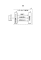
- FIG. 1 shows the configuration example of the battery deterioration prediction system provided with the battery deterioration prediction apparatus which concerns on Embodiment 1.
- the figure used for the explanation of the preliminary experiment in Embodiment 1. A block diagram showing an example of a hardware configuration that embodies the functions of the arithmetic unit according to the first embodiment.
- FIG. 1 is a diagram showing a configuration example of a battery deterioration prediction system including the battery deterioration prediction device according to the first embodiment.
- the battery deterioration prediction system 100 according to the first embodiment includes a battery 1 and a battery deterioration prediction device 10.
- the battery deterioration prediction device 10 includes a battery monitoring device 2 and an arithmetic unit 3.
- Battery 1 is a rechargeable and dischargeable secondary battery.
- An example of a secondary battery is a lithium ion battery.
- the description assumes that the battery 1 is a lithium ion battery, but the description is not limited to this.
- the battery 1 has a capacity deterioration mechanism due to the elution of the positive electrode component into the battery solution, it can be applied to the battery.
- Another example of the battery 1 is a lead storage battery, a nickel hydrogen battery, and the like.
- the deterioration of the battery 1 progresses, the energy capacity that can be charged decreases, or the maximum power that can be supplied decreases. Further, in the battery 1, the electrodes expand and contract due to repeated charge / discharge cycles, and fatigue fracture causes deterioration phenomena such as peeling of the electrode material. Deterioration associated with such charging / discharging is called cycle deterioration. The degree of cycle deterioration changes depending on the influence of the current value at the time of charging / discharging, the temperature, the range of the charging rate to be cycled, and the like.
- the battery monitoring device 2 monitors the charge rate SOC of the battery 1 and the temperature T of the battery 1.
- the arithmetic unit 3 receives information on the temperature T, the elapsed time t, and the charge rate SOC from the battery monitoring device 2.
- the elapsed time t is the elapsed time since the battery monitoring device 2 started monitoring the battery 1, or the elapsed time from the previous reception to the current reception.
- the arithmetic unit 3 calculates the remaining capacity rate f (t) of the battery 1 by the following equation (1) based on the charge rate SOC, the temperature T, and the elapsed time t.
- the remaining capacity rate f (t) represents the ratio of the elapsed time t to the initial capacity of the battery 1. If the remaining capacity f (t) of the battery 1 is known, it is possible to predict the deterioration state of the battery 1, that is, the degree of deterioration, which is the degree of deterioration.
- the battery 1 in the first embodiment has a deterioration mechanism in which the capacity of the battery 1 is deteriorated by elution of a part of the components of the electrodes into the solution of the battery 1.
- this deterioration mechanism is appropriately referred to as a "first deterioration mechanism".
- the above equation (1) is an equation in consideration of the first deterioration mechanism.
- the reaction rate at which the electrode component elutes into the battery solution is expressed by the following equation (2) as a primary reaction depending on the concentration and time of the electrode component.
- C A is the concentration of the electrode component
- a is a reaction rate constant
- t is time.
- volume and concentration of the electrode component is proportional to the battery capacity, the value of "C A / C A0" be defined as a residual capacity rate of the battery, based on the equation (4) shown above (1)
- the residual rate f (t) can be derived.
- Equation (1) can be expressed as the following equation (5) by transforming it using "1-exp (-a ⁇ t)" representing the first deterioration rate defined above.
- the reaction rate constant a is a coefficient multiplied by the time t. Therefore, the reaction rate constant a can be treated as a deterioration coefficient that determines the deterioration rate of the positive electrode in the battery 1 having the first deterioration mechanism.
- the reaction rate constant is referred to as a "deterioration coefficient" in the present specification.
- the deterioration coefficient of the positive electrode may be described as "first deterioration coefficient".
- the deterioration coefficient a is temperature-dependent and can be expressed by the following equation (6) according to the Arrhenius equation having the frequency factor As and the activation energy Es.
- R is a gas constant and T is a temperature.
- Ln (As) which is the natural logarithm of the activation energy Es and the frequency factor As, is dependent on the charge rate SOC and has a proportional relationship with the charge rate SOC.
- the activation energy Es can be expressed by the linear equation of the charge rate SOC as in the following equation (7) using the constants c and d.
- the frequency factor As can be expressed by the linear equation of the charge rate SOC as in the following equation (8) using the constants g and h.
- the deterioration coefficient a can be calculated by measuring the temperature T of the battery 1 and the charge rate SOC of the battery 1 for the battery 1 having the first deterioration mechanism. Will be possible.
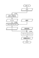
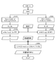
- FIG. 2 is a flowchart showing a deterioration prediction processing flow in the battery deterioration prediction device according to the first embodiment. The process of FIG. 2 is executed by the arithmetic unit 3.
- step S101 the charge rate SOC information input from the battery monitoring device 2 is used.
- the arithmetic unit 3 calculates the natural logarithm ln (As) of the activation energy Es and the frequency factor As based on the above equations (7) and (8).
- the constants c, d, g, and h required for the calculation of the natural logarithm ln (As) of the activation energy Es and the frequency factor As can be prepared in advance by performing a storage test on the battery to be predicted.
- step S102 the information of the activation energy Es and the frequency factor As calculated in the step S101 and the information of the temperature T input from the battery monitoring device 2 are used.
- step S102 the arithmetic unit 3 calculates the deterioration coefficient a based on the above equation (6).
- step S103 the information of the deterioration coefficient a calculated in step S102 and the information of the elapsed time t input from the battery monitoring device 2 are used.
- the arithmetic unit 3 calculates the remaining capacity rate f (t) of the battery 1 at the elapsed time t based on the above equation (5) or the above equation (1).
- the elapsed time is also referred to as "storage time".
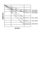
- FIG. 3 is a diagram used for explaining the preliminary experiment in the first embodiment.
- T1 ⁇ T2 between the above T1 and T2.
- SOC1> SOC2> SOC3 between SOC1 and SOC3.
- each graph of test 1 to test 6 is fitted to f (t) using the least squares method, and the a value is calculated for each test.
- the a value is the value of the deterioration coefficient a.
- the calculated a value is stored in the arithmetic unit 3.
- the activation energy Es of electrode deterioration in each SOC can be calculated. Further, the frequency factor As of electrode deterioration can be calculated from the obtained straight line intercept ln (As).
- the activation energy Es and the frequency factor As in the case of different SOC values are also calculated.
- Each of the activation energy Es and the frequency factor As calculated with several SOC values is plotted against the SOC value. Although detailed results are omitted here, good linear approximation formulas are obtained for both the activation energy Es for the SOC value and the frequency factor As for the SOC value.
- the constant c can be obtained from the slope, and the constant d can be obtained from the intercept.
- the constant g can be obtained from the slope thereof, and the constant h can be obtained from the intercept.
- the constants c, d, g, and h can be prepared.
- the calculated constants c, d, g, and h are held in the arithmetic unit 3.
- the capacity remaining rate f (t) at an arbitrary elapsed time t can be calculated by the following procedure.
- the activation energy Es and the frequency factor As required for calculating the deterioration coefficient a are calculated based on the SOC at the time of storage of the battery 1 to be predicted and the prepared constants c, d, g, and h. ..
- the deterioration coefficient a is calculated based on the calculated activation energy Es and the frequency factor As and the temperature T at the time of storage.
- the capacity remaining rate f (t) is calculated based on the calculated deterioration coefficient a and the elapsed time t.
- the remaining capacity CAP of the battery 1 can be calculated using the following equation (9).
- CAP_0 is the initial capacity of the battery 1.
- a storage test in an environment with a minimum small number of levels (6 levels in the above example) and SOC in advance within the planned storage range of the battery 1 can be performed.
- constants c, d, g, and h for obtaining the deterioration coefficient a in the range of the battery 1 scheduled to be stored can be obtained.
- the deterioration coefficient a at the elapsed time t can be calculated.
- the remaining capacity rate f (t) of the battery 1 and the remaining capacity CAP of the battery 1 at the elapsed time t can be calculated.
- the storage charge rate at the scheduled time t and the capacity remaining rate at the storage temperature Calculate f (t). Then, the initial capacity CAP_0 of the battery 1 is calculated so that the remaining capacity CAP of the battery 1 calculated by the product of the initial capacity CAP_0 of the battery 1 and the remaining capacity rate f (t) becomes the required value required in the time t. To decide. Thereby, the mounting amount of the battery 1 can be determined.
- the charge rate SOC is stored at SOC_1 and the temperature T is stored at T_1
- the second time t_1 From to the third time t_2, consider the conditions under which the charge rate SOC is stored at SOC_1 and the temperature T is stored at T_2.
- the capacity remaining rate f (t) _1 at the second time t_1 can be calculated using SOC_1 and T_1.
- the remaining capacity CAP_1 at the second time t_1 can be calculated by the product of the capacity remaining ratio f (t) _1 and the initial capacity CAP_1.
- the capacity remaining rate f (t) _2 at the third time t_2 can be calculated using SOC_2 and T_2. Further, the remaining capacity CAP_2 at the third time t_2 can be calculated by the product of the capacity remaining ratio f (t) _2 and the remaining capacity CAP_1 at the second time t_1.
- t_x Even if the environmental temperature changes depending on the environment in which the battery 1 is installed or the season, for example, by repeating the same calculation based on the average temperature for each month and the charge rate during the same period, t_x for an arbitrary time.
- the remaining capacity CAP_x in can be calculated. Even when the storage charge rate is scheduled to change, the remaining capacity CAP_x at an arbitrary time t_x can be calculated by repeating the same calculation process.
- the remaining capacity CAP_x required in the final time t_x can be obtained.
- the initial capacity CAP_0 can be determined. Therefore, if the method of the first embodiment is used, the required battery loading amount can be estimated accurately.
- the storage temperature and the storage charge rate are monitored by the battery monitoring device 2.
- the battery monitoring device 2 monitors that the charge rate SOC is stored at SOC_3 and the temperature T is stored at T_3 from the fourth time t_3 to the fifth time t_4.
- the capacity remaining rate f (t) _3 in the fourth time t_3 is calculated by inputting the measured values of SOC_3 and T_3 from the fourth time t_3 to the fifth time t_4 into the arithmetic unit 3. Can be done.
- the remaining capacity CAP_3 at the fourth time t_3 can be calculated by the product of the capacity remaining ratio f (t) _3 and the initial capacity CAP_0.
- the battery monitoring device 2 monitors that the charge rate SOC is stored at SOC_4 and the temperature T is stored at T_4 from the fifth time t_4 to the sixth time t_5.
- the capacity remaining rate f (t) _4 at the fifth time t_4 is calculated by inputting the measured values of SOC_4 and T_4 from the fifth time t_4 to the sixth time t_5 into the arithmetic unit 3. Can be done.
- the remaining capacity CAP_4 at the fifth time t_4 can be calculated by the product of the capacity remaining ratio f (t) _4 and the remaining capacity CAP_3 at the fourth time t_3.
- the remaining capacity CAP_x at an arbitrary time t_x can be calculated based on the measured temperature T and charge rate SOC information.
- the storage temperature and storage charge rate assumed at the design stage are changed during actual operation, it is expected that the deterioration state of the battery 1 will be different from the state assumed at the design stage. Even in such a case, by inputting the measured values of the storage temperature and the storage charge rate into the arithmetic unit 3, the predicted values can be corrected according to the actual operation.
- the same prediction is possible when the value of the remaining capacity CAP_x at an arbitrary time t_x is corrected according to the actual operation and then the storage is continued from the time t_x to the time t_xx after that.
- the capacity remaining rate f (t) _xx is calculated based on the information of the storage charge rate SOC_xx and the temperature T_xx scheduled by the time t_xx.
- the CAP_xx is calculated by the product of the remaining capacity CAP_x at the time t_x and the capacity remaining ratio f (t) _xx.
- the battery 1 can be used.
- the predicted value of the remaining capacity can be corrected. This makes it possible to predict the timing of maintenance, inspection, replacement, etc. of the battery 1. Further, even when the storage conditions of the temperature T and the charge rate SOC are changed, the predicted values can be corrected.
- the arithmetic unit has the remaining capacity of the battery based on the charge rate, the temperature, and the elapsed time from the start of monitoring the battery. Is calculated.
- the capacity residual ratio is calculated using a first functional expression including the first expression.
- the first equation includes an exponential function whose variable is the value obtained by multiplying the elapsed time by the first deterioration coefficient and -1.
- the battery deterioration prediction device predicts the deterioration state of the battery based on the capacity remaining rate calculated by using the first functional expression. As a result, even if the target of deterioration prediction is a battery having the first deterioration mechanism, it is possible to predict the deterioration state.
- the arithmetic unit uses the information of the temperature and the charge rate taken in from the battery monitoring device by the elapsed time before the present, and the above constant c. , D, g, h can be used to calculate the current degradation factor a. Then, based on the calculated current deterioration coefficient a, the current capacity remaining rate and the future capacity remaining rate in the elapsed time after the present can be calculated. Thereby, it is possible to predict the deterioration of the battery at an arbitrary elapsed time under the condition that at least one of the temperature and the charge rate of the battery is different.
- the constants c, d, g, and h prepared in advance can be used only by changing the temperature, the SOC, and the input value of the elapsed time. Since it is not necessary to prepare a new constant, it is possible to reduce the load on the arithmetic unit.
- the preparation method for battery deterioration prediction according to the first embodiment can be a process including the first step to the seventh step shown below.
- the battery to be predicted is stored under the condition of combining several points of the predetermined charge rate and several points of the predetermined temperature.
- the remaining capacity of the battery is measured for each storage time.
- a process of fitting an expression representing the capacity remaining rate to the graph plotted against the storage time is performed.
- the fourth step the first deterioration coefficient at an arbitrary elapsed time is calculated.
- the natural logarithmic value of the first deterioration coefficient obtained in the fourth step is plotted against the reciprocal of the temperature to obtain a linear approximation formula.
- the frequency factor and activation energy are calculated based on this.
- the frequency factor and the activation energy are calculated with a charge rate different from the charge rate used in the fifth step.
- the constant used for predicting the deterioration of the battery is calculated based on the linear approximation formula obtained by plotting the frequency factor and the activation energy obtained in the 5th step and the 6th step against the charge rate. ..
- the range of the battery to be stored is planned by conducting a storage test in an environment with a minimum low level of temperature and charge rate. It is possible to obtain a constant for obtaining the first deterioration coefficient in.
- the first deterioration coefficient in the elapsed time can be calculated by inputting the temperature, the charge rate, and the elapsed time from the battery monitoring device to the arithmetic unit while suppressing the load on the arithmetic unit. Further, it is possible to calculate the remaining capacity of the battery and the remaining capacity of the battery in the elapsed time while suppressing the load on the arithmetic unit.
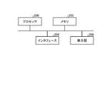
- FIG. 4 is a block diagram showing an example of a hardware configuration that realizes the function of the arithmetic unit according to the first embodiment.
- FIG. 5 is a block diagram showing another example of the hardware configuration that realizes the function of the arithmetic unit according to the first embodiment.
- the processor 200 When a part or all of the functions of the arithmetic unit 3 in the first embodiment are realized, the processor 200, the memory 202, the interface 204 for inputting / outputting signals, and the arithmetic information are displayed as shown in FIG. Can be configured to include a display 206 for the purpose.
- the processor 200 performs the above-mentioned arithmetic processing.
- the memory 202 is a program read by the processor 200, and stores a program that executes the function of the arithmetic unit 3 in the first embodiment.
- the memory 202 is also used as a work area for arithmetic processing of the processor 200.
- Interface 204 provides an environment for signal input / output between the arithmetic unit 3 and the battery monitoring device 2.
- the display 206 displays the result of the arithmetic processing performed by the arithmetic unit 3 as needed.
- the processor 200 may be an arithmetic unit such as an arithmetic unit, a microprocessor, a microcomputer, a CPU (Central Processing Unit), or a DSP (Digital Signal Processor).
- the memory 202 includes a non-volatile or volatile semiconductor memory such as a RAM (Radom Access Memory), a ROM (Read Only Memory), a flash memory, an EPROM (Erasable Project ROM), and an EEPROM (registered trademark) (Electrically EPROM). Examples thereof include magnetic discs, flexible discs, optical discs, compact discs, mini discs, and DVDs (Digital Versaille Disc).
- the processor 200 sends and receives necessary information via the interface 204, the processor 200 executes a program stored in the memory 202, and the processor 200 refers to a table stored in the memory 202 to perform the above-mentioned processing. It can be carried out.
- the constants c, d, g, h created in advance and the constants i, j, m, n used in the second embodiment described later are stored in the table.
- the calculation result by the processor 200 can be stored in the memory 202.
- the processing circuit 203 shown in FIG. 5 can also be used.
- the processing circuit 203 corresponds to a single circuit, a composite circuit, an ASIC (Application Specific Integrated Circuit), an FPGA (Field-Programmable Gate Array), or a combination thereof.
- the information input to the processing circuit 203 and the information output from the processing circuit 203 can be obtained via the interface 204.
- processing in the arithmetic unit 3 may be performed in the processing circuit 203, and processing not performed in the processing circuit 203 may be performed in the processor 200 and the memory 202.
- Embodiment 2 Next, the second embodiment will be described.
- the configuration of the battery deterioration prediction system including the battery deterioration prediction device according to the second embodiment is the same as the configuration of the battery deterioration prediction system 100 according to the first embodiment.
- the type of the battery 1 is different between the second embodiment and the first embodiment.
- the parts different from the first embodiment will be mainly described, and the description of the overlapping contents will be omitted as appropriate.
- the battery 1 in the second embodiment has the first deterioration mechanism described in the first embodiment.
- the battery 1 in the second embodiment further has a deterioration mechanism in which the capacity is deteriorated by the growth of a passivation film (Solid Electrolyte Interphase: SEI) on the negative electrode of the battery 1.
- SEI Solid Electrolyte Interphase
- the deterioration mechanism relating to the negative electrode is appropriately referred to as a “second deterioration mechanism”.
- the battery monitoring device 2 monitors the charge rate SOC of the battery 1 and the temperature T of the battery 1.
- the arithmetic unit 3 receives information on the temperature T, the elapsed time t, and the charge rate SOC from the battery monitoring device 2.
- the elapsed time t is the elapsed time since the battery monitoring device 2 started monitoring the battery 1, or the elapsed time from the previous reception to the current reception.
- the arithmetic unit 3 in the second embodiment calculates the remaining capacity f (t) of the battery 1 by the following equation (10) based on the charge rate SOC, the temperature T, and the elapsed time t.
- Deterioration of the negative electrode is caused by the growth of a passivation film deposited on the surface of the negative electrode due to a side reaction of the electrolytic solution.
- “B ⁇ t ⁇ (1/2)” in the above equation (10) represents the deterioration rate of the negative electrode in the second deterioration mechanism.
- the deterioration rate of the negative electrode may be referred to as a “second deterioration rate”.
- the coefficient b multiplied by the square root "t ⁇ (1/2)" of the time t is a deterioration coefficient that determines the deterioration rate of the negative electrode.
- the coefficient b is referred to as a "deterioration coefficient b" in the present specification.
- the deterioration coefficient b may be described as a "second deterioration coefficient" in order to distinguish it from the deterioration coefficient a of the positive electrode.
- the deterioration coefficient b is temperature-dependent and can be expressed by the following equation (11) according to the Arrhenius equation having the frequency factor Af and the activation energy Ef.
- R is a gas constant and T is a temperature.
- the natural logarithm of the activation energy Ef and the frequency factor Af, ln (Af), is dependent on the charge rate SOC and has a proportional relationship with the charge rate SOC.
- the activation energy Ef can be expressed by the linear equation of the charge rate SOC as in the following equation (12) using the constants i and j.
- the frequency factor Af can be expressed by the linear equation of the charge rate SOC as in the following equation (13) using the constants m and n.
- the deterioration coefficient b can be calculated by measuring the temperature T of the battery 1 and the charge rate SOC of the battery 1 for the battery having the second deterioration mechanism. It will be possible.
- the former In order to distinguish between the frequency factor As related to the deterioration of the positive electrode and the frequency factor Af related to the deterioration of the negative electrode, the former is described as the “first frequency factor” and the latter is described as the “second frequency factor”. It may be described as "factor”. Further, in order to distinguish between the activation energy Es related to the deterioration of the positive electrode and the activation energy Ef related to the deterioration of the negative electrode, the former is described as “first activation energy” and the latter is described as “first activation energy”. It may be described as "activation energy of 2.”
- FIG. 6 is a flowchart showing a deterioration prediction processing flow in the battery deterioration prediction device according to the second embodiment.
- the processing content that is the same as or equivalent to that in FIG. 2 is indicated by the same reference numerals as those in FIG.
- the process of FIG. 6 is executed by the arithmetic unit 3.
- step S201 the arithmetic unit 3 calculates the natural logarithm ln (Af) of the activation energy Ef and the frequency factor Af based on the above equations (12) and (13).
- the constants i, j, m, and n required for the calculation of the natural logarithm ln (Af) of the activation energy Ef and the frequency factor Af can be prepared in advance by performing a storage test on the battery to be predicted.
- step S202 the information of the activation energy Ef and the frequency factor Af calculated in the step S201 and the information of the temperature T input from the battery monitoring device 2 are used.
- step S202 the arithmetic unit 3 calculates the deterioration coefficient b based on the above equation (11).
- step S203 the information of the deterioration coefficient a calculated in step S102, the information of the deterioration coefficient b calculated in step S202, and the information of the elapsed time t input from the battery monitoring device 2 are used. Be done.
- the arithmetic unit 3 calculates the remaining capacity rate f (t) of the battery 1 at the elapsed time t based on the above equation (10).
- the constants i, j, m, and n used in the calculation of the deterioration coefficient b can be calculated in advance by the same method as in the first embodiment.
- the calculation method is the same as that of the first embodiment, and the description thereof is omitted here.
- the constants c, d, g, h, i, j, m, and n calculated in advance are stored in the arithmetic unit 3.
- the capacity remaining rate f (t) at an arbitrary elapsed time t can be calculated by the following procedure.
- the activation energy Es and the frequency factor As required for calculating the deterioration coefficient a are calculated based on the SOC at the time of storage of the battery 1 to be predicted and the prepared constants c, d, g, and h. ..
- the deterioration coefficient a is calculated based on the calculated activation energy Es and the frequency factor As and the temperature T at the time of storage.
- the activation energy Ef and the frequency factor Af required to calculate the deterioration coefficient b are calculated based on the SOC of the battery 1 to be predicted at the time of storage and the prepared constants i, j, m, and n. do.
- the deterioration coefficient b is calculated based on the calculated activation energy Ef and the frequency factor Af and the temperature T at the time of storage.
- the capacity remaining rate f (t) is calculated based on the calculated deterioration coefficients a and b and the elapsed time t.
- the remaining capacity CAP of the battery 1 can be calculated using the above equation (9).
- a storage test in an environment with a minimum small number of levels (6 levels in the above example) and SOC in advance within the planned storage range of the battery 1 can be performed.
- constants c, d, g, h, i, j, m and n for obtaining the deterioration coefficients a and b in the range of the battery 1 scheduled to be stored can be obtained.
- the deterioration coefficients a and b at the elapsed time t can be calculated.
- the remaining capacity rate f (t) of the battery 1 and the remaining capacity CAP of the battery 1 at the elapsed time t can be calculated.
- the arithmetic unit has the remaining capacity of the battery based on the charge rate, the temperature, and the elapsed time from the start of monitoring the battery. Is calculated.
- the capacity residual ratio is calculated using a second function formula including the first formula and the second formula.
- the first equation includes an exponential function whose variable is the value obtained by multiplying the elapsed time by the first deterioration coefficient and -1.
- the second equation includes a square root function whose variable is the value obtained by multiplying the square root of the elapsed time by the second deterioration coefficient.
- the battery deterioration prediction device predicts the deterioration state of the battery based on the capacity remaining rate calculated by using the second functional expression. As a result, even if the target of deterioration prediction is a battery having the first and second deterioration mechanisms, it is possible to predict the deterioration state.
- the arithmetic unit uses the information of the temperature and the charge rate taken in from the battery monitoring device by the elapsed time before the present, and the above constant c. , D, g, h, i, j, m, n can be used to calculate the current first and second degradation coefficients. Then, based on the calculated current first and second deterioration coefficients, the current capacity remaining rate and the future capacity remaining rate in the elapsed time after the present can be calculated. Thereby, it is possible to predict the deterioration of the battery at an arbitrary elapsed time under the condition that at least one of the temperature and the charge rate of the battery is different.
- the constants c, d, g, h, i, j, m, n prepared in advance can be used only by changing the temperature, the SOC, and the input value of the elapsed time. .. Since it is not necessary to prepare a new constant, it is possible to reduce the load on the arithmetic unit.
- the preparation method for battery deterioration prediction according to the second embodiment can be a process including the first step to the ninth step shown below.
- the battery to be predicted is stored under the condition of combining several points of the predetermined charge rate and several points of the predetermined temperature.
- the remaining capacity of the battery is measured for each storage time.
- a process of fitting an expression representing the capacity remaining rate to the graph plotted against the storage time is performed.
- the fourth step the first and second deterioration coefficients at an arbitrary elapsed time are calculated.
- the fifth step those having the same charge rate but different temperatures are extracted, and the natural logarithmic value of the first deterioration coefficient obtained in the fourth step is plotted against the reciprocal of the temperature to obtain a linear approximation formula. Based on this, the first frequency factor and the first activation energy are calculated.
- the sixth step the first frequency factor and the first activation energy are calculated with a charge rate different from the charge rate used in the fifth step.
- the 7th step those with the same charge rate but different temperatures are extracted, and the natural logarithmic value of the 2nd deterioration coefficient obtained in the 4th step is plotted against the reciprocal of the temperature to obtain a linear approximation formula. Based on this, the second frequency factor and the second activation energy are calculated.
- the second frequency factor and the second activation energy are calculated with a charge rate different from the charge rate used in the seventh step.
- the linear approximation formula obtained by plotting the first frequency factor and the first activation energy obtained in the fifth and sixth steps against the charge rate and in the seventh and eighth steps. Based on the linear approximation formula obtained by plotting the obtained second frequency factor and the second activation energy against the charge rate, the constant used for predicting the deterioration of the battery is calculated.
- the first deterioration coefficient in the elapsed time can be calculated by inputting the temperature, the charge rate, and the elapsed time from the battery monitoring device to the arithmetic unit while suppressing the load on the arithmetic unit. Further, it is possible to calculate the remaining capacity of the battery and the remaining capacity of the battery in the elapsed time while suppressing the load on the arithmetic unit.
- the configuration shown in the above embodiments is an example, and can be combined with another known technique, can be combined with each other, and does not deviate from the gist. It is also possible to omit or change a part of the configuration.
Landscapes
- Physics & Mathematics (AREA)
- General Physics & Mathematics (AREA)
- Engineering & Computer Science (AREA)
- Manufacturing & Machinery (AREA)
- Chemical & Material Sciences (AREA)
- Chemical Kinetics & Catalysis (AREA)
- Electrochemistry (AREA)
- General Chemical & Material Sciences (AREA)
- Power Engineering (AREA)
- Charge And Discharge Circuits For Batteries Or The Like (AREA)
- Secondary Cells (AREA)
- Tests Of Electric Status Of Batteries (AREA)
Abstract
バッテリ劣化予測装置(10)は、バッテリ(1)の充電率SOC及びバッテリ(1)の温度Tを監視するバッテリ監視装置(2)と、充電率SOC、温度T、及びバッテリ(1)の監視を開始してからの経過時間tに基づいてバッテリ(1)の容量残存率f(t)を演算する演算装置(3)とを備える。容量残存率f(t)は、第1式を含む第1の関数式を用いて演算される。第1式は、経過時間tに劣化係数aとマイナス1とを乗じた値を変数とする指数関数を含む。バッテリ劣化予測装置(10)は、第1の関数式を用いて演算された容量残存率f(t)に基づいてバッテリの劣化状態を予測する。
Description
本開示は、バッテリの劣化状態を予測するバッテリ劣化予測装置、バッテリ劣化予測システム、及びバッテリ劣化予測のための準備方法に関する。
バッテリがリチウムイオン電池の場合、従来のバッテリ劣化予測装置では、負極電極の劣化を主要因と考え、使用時間の平方根から求められる劣化率に基づいてバッテリの容量残存率を演算、演算された容量残存率に基づいてバッテリの寿命を予測する手法が多く用いられている。
上記の従来手法に対し、下記特許文献1には、更に正極電極の劣化を考慮し、正負の2種類の電極の劣化式を組み合わせた関数式に基づいてバッテリの容量残存率を推定する手法が開示されている。具体的に、特許文献1の手法では、正極電極の劣化を主要因とする容量劣化については、使用時間に正の定数を乗じた値を変数とする指数関数を用いて表現されている。また、負極電極の劣化による容量劣化については、使用時間についての平方根関数を用いて表現されている。
特許文献1の手法における正極側の劣化式は、バッテリの寿命末期において急激に変化する劣化特性を表しているが、保存初期における正極電極の劣化特性を表していない。このため、特許文献1の手法では、特に、正極電極の成分がバッテリ溶液内に溶出することで容量が低下するという劣化機構を有するバッテリの場合、容量残存率の推定が正確に行えないという問題がある。従って、特許文献1の手法では、電極成分のバッテリ溶液内への溶出に起因する劣化機構を有するバッテリの場合には、バッテリの劣化状態の予測が困難であった。
本開示は、上記に鑑みてなされたものであって、電極成分のバッテリ溶液内への溶出に起因する劣化機構を有するバッテリの場合であっても、バッテリの劣化状態の予測が可能となるバッテリ劣化予測装置を得ることを目的とする。
上述した課題を解決し、目的を達成するため、本開示に係るバッテリ劣化予測装置は、バッテリの電極の成分の一部がバッテリの溶液内に溶出することで容量が劣化する第1の劣化機構を有するバッテリの劣化状態を予測するバッテリ劣化予測装置である。バッテリ劣化予測装置は、バッテリ監視装置と、演算装置とを備える。バッテリ監視装置は、バッテリの充電率及びバッテリの温度を監視する。演算装置は、充電率、温度、及びバッテリの監視を開始してからの経過時間に基づいて、バッテリの容量残存率を演算する。容量残存率は、第1式を含む第1の関数式を用いて演算される。第1式は、経過時間に第1の劣化係数とマイナス1とを乗じた値を変数とする指数関数を含む。バッテリ劣化予測装置は、第1の関数式を用いて演算された容量残存率に基づいてバッテリの劣化状態を予測する。
本開示に係るバッテリ劣化予測装置によれば、電極成分のバッテリ溶液内への溶出に起因する劣化機構を有するバッテリの場合であっても、バッテリの劣化状態の予測が可能になるという効果を奏する。
以下に添付図面を参照し、本開示の実施の形態に係るバッテリ劣化予測装置、バッテリ劣化予測システム、及びバッテリ劣化予測のための準備方法について詳細に説明する。
実施の形態1.
図1は、実施の形態1に係るバッテリ劣化予測装置を備えたバッテリ劣化予測システムの構成例を示す図である。実施の形態1に係るバッテリ劣化予測システム100は、バッテリ1と、バッテリ劣化予測装置10とを備える。バッテリ劣化予測装置10は、バッテリ監視装置2と、演算装置3とを備える。
図1は、実施の形態1に係るバッテリ劣化予測装置を備えたバッテリ劣化予測システムの構成例を示す図である。実施の形態1に係るバッテリ劣化予測システム100は、バッテリ1と、バッテリ劣化予測装置10とを備える。バッテリ劣化予測装置10は、バッテリ監視装置2と、演算装置3とを備える。
バッテリ1は、充放電可能な二次電池である。二次電池の一例は、リチウムイオン電池である。以下、バッテリ1がリチウムイオン電池である場合を想定した説明とするが、これに限定されない。バッテリ1が正極電極成分のバッテリ溶液内への溶出に起因する容量劣化機構を有するものである場合、当該バッテリへの適用が可能である。バッテリ1の他の例は、鉛蓄電池、ニッケル水素電池などである。
リチウムイオン電池などの二次電池は、使用しない状態、つまり充放電を行っていない状態であっても劣化が生じることが知られている。この劣化は、保存劣化と呼ばれる。バッテリ1が使用されていない保存状態である場合、外部回路に電流が流れなくても、内部の活物質が酸化還元反応して少しずつ放電する。放電した電荷は、充電によって戻すことができる可逆過程と、回復せずに劣化につながる不可逆過程とがある。保存劣化は、充電率及び温度の影響によって進行度合いが変化する。充電率は、SOC(State Of Charge)とも呼ばれる。以下、本明細書では、充電率を「SOC」と呼ぶ。また、本明細書では、「SOC」を記号として扱って、「充電率SOC」と表記する場合がある。
バッテリ1の劣化が進行した場合、充電できるエネルギー容量が低下したり、供給できる最大パワーが低下したりする。また、バッテリ1は、充放電サイクルを繰り返すことで電極が膨張収縮し、疲労破壊によって、電極材料が剥離するなどの劣化現象が生じる。このような充放電に伴う劣化は、サイクル劣化と呼ばれている。サイクル劣化は、充放電時の電流値、温度、サイクルする充電率の範囲などの影響で進行度合いが変化する。
バッテリ監視装置2は、バッテリ1の充電率SOC及びバッテリ1の温度Tを監視する。演算装置3は、バッテリ監視装置2から温度T、経過時間t、充電率SOCの情報を受信する。経過時間tは、バッテリ監視装置2がバッテリ1の監視を開始してからの経過時間、又は前回の受信から今回の受信までの経過時間である。演算装置3は、充電率SOC、温度T及び経過時間tに基づいて、以下の(1)式により、バッテリ1の容量残存率f(t)を演算する。
f(t)=exp(-a×t)…(1)
上記(1)式において、容量残存率f(t)は、経過時間tにおけるバッテリ1の初期容量に対する比率を表している。バッテリ1の容量残存率f(t)が分かれば、バッテリ1の劣化状態、即ち劣化の程度である劣化度の予測が可能となる。
実施の形態1におけるバッテリ1は、電極の成分の一部がバッテリ1の溶液内に溶出することで、バッテリ1の容量が劣化する劣化機構を有している。本明細書では、この劣化機構を適宜「第1の劣化機構」と呼ぶ。上記(1)式は、第1の劣化機構を考慮した式となっている。
また、上記(1)式を変形した“1-exp(-a×t)”の式を考える。この式は、第1の劣化機構における電極の劣化率を表すことになる。なお、第1の劣化機構による劣化は、正極電極が主である。このため、以下では、説明の対象を正極電極とする。また、正極電極の劣化率を「第1の劣化率」と記載する場合がある。
次に、上記(1)式の導出手順について説明する。まず、電極の成分がバッテリ溶液内に溶出する反応速度を、電極成分の濃度と時間とに依存する一次反応として、以下の(2)式で表す。
-dCA/dt=a×CA…(2)
上記(2)式において、CAは電極成分の濃度であり、aは反応速度定数であり、tは時間である。
上記(2)式をt=0、CA=CA0で積分すると、以下の(3)式で表される。
ln(CA/CA0)=-a×t…(3)
上記(3)式を変形すると、以下の(4)式が得られる。
CA=CA0×exp(-a×t)…(4)
よって、“CA/CA0”の対数値を時間に対してプロットしたグラフにおいて、プロットした値を結ぶ直線の勾配から、“-a”の値を得ることができる。
電極成分の濃度がバッテリ容量に比例するとし、“CA/CA0”の値をバッテリの容量残存率と定義すれば、上記(4)式に基づいて、上記(1)式で示した容量残存率f(t)を導くことができる。
f(t)=exp(-a×t)…(1)(再掲)
上記(1)式は、先に定義した第1の劣化率を表す“1-exp(-a×t)”を用いて変形すると、以下の(5)式のように表すことができる。
f(t)=1-{1-exp(-a×t)}…(5)
なお、以下では、上記(5)式における“exp(-a×t)”を「第1式」と記載し、“1-{1-exp(-a×t)}”を「第1の関数式」と記載する場合がある。
また、上記(4)式に示されるように、反応速度定数aは、時間tに乗算される係数となる。従って、反応速度定数aは、第1の劣化機構を有するバッテリ1においては、正極電極の劣化率を決める劣化係数として取り扱うことができる。この意味で、本明細書においては、反応速度定数を「劣化係数」と呼ぶ。なお、後述する負極電極の劣化係数と区別するため、正極電極の劣化係数を「第1の劣化係数」と記載する場合がある。
劣化係数aは、温度に依存性が有り、頻度因子Asと活性化エネルギーEsとを有するアレニウス式に従って、以下の(6)式で表すことができる。
a=As×exp(-Es/RT)…(6)
上記(6)式において、Rは気体定数であり、Tは温度である。
活性化エネルギーEs及び頻度因子Asの自然対数値であるln(As)は、充電率SOCに対する依存性があり、充電率SOCに対してそれぞれ比例関係を有する。
従って、活性化エネルギーEsは、定数c,dを用いて、以下の(7)式のように、充電率SOCの一次式で表すことができる。
Es=c×SOC+d…(7)
同様に、頻度因子Asは、定数g,hを用いて、以下の(8)式のように、充電率SOCの一次式で表すことができる。
ln(As)=g×SOC+h…(8)
上記(6)~(8)式を用いれば、第1の劣化機構を有するバッテリ1に対し、バッテリ1の温度Tとバッテリ1の充電率SOCを測定することで、劣化係数aを演算することが可能になる。
次に、実施の形態1に係るバッテリ劣化予測装置10における劣化予測処理のフローについて説明する。図2は、実施の形態1に係るバッテリ劣化予測装置における劣化予測の処理フローを示すフローチャートである。図2の処理は、演算装置3によって実行される。
ステップS101の処理では、バッテリ監視装置2から入力される充電率SOCの情報が用いられる。ステップS101において、演算装置3は、上記(7),(8)式に基づいて、活性化エネルギーEs及び頻度因子Asの自然対数値ln(As)を演算する。活性化エネルギーEs及び頻度因子Asの自然対数値ln(As)の演算に必要な定数c,d,g,hは、予め、予測対象のバッテリに対する保存試験を行うことで準備することができる。
次のステップS102の処理では、ステップS101で演算された活性化エネルギーEs及び頻度因子Asの情報と、バッテリ監視装置2から入力される温度Tの情報とが用いられる。ステップS102において、演算装置3は、上記(6)式に基づいて、劣化係数aを演算する。
次のステップS103の処理では、ステップS102で演算された劣化係数aの情報と、バッテリ監視装置2から入力される経過時間tの情報とが用いられる。ステップS103において、演算装置3は、上記(5)式、又は上記(1)式に基づいて、経過時間tにおけるバッテリ1の容量残存率f(t)を演算する。なお、バッテリ1が非使用の状態、即ち保存状態にある場合、経過時間は「保存時間」とも呼ばれる。
劣化係数aの演算に用いる定数c,d,g,hについては、例えば実験により、事前に算出しておく。以下、具体的な処理手順について、図3を参照して説明する。図3は、実施の形態1における事前実験の説明に使用する図である。
図3の横軸は保存時間tを表し、縦軸は容量残存率f(t)を表している。また、図3には、温度Tについて2水準、充電率SOCについて3水準、合計で2×3=6水準のテストパターンによる容量残存率f(t)のプロット値が示されている。各テストパターンの内容は、以下の通りである。
テスト1:T=T1,SOC=SOC1
テスト2:T=T2,SOC=SOC1
テスト3:T=T1,SOC=SOC2
テスト4:T=T2,SOC=SOC2
テスト5:T=T1,SOC=SOC3
テスト6:T=T2,SOC=SOC3
テスト2:T=T2,SOC=SOC1
テスト3:T=T1,SOC=SOC2
テスト4:T=T2,SOC=SOC2
テスト5:T=T1,SOC=SOC3
テスト6:T=T2,SOC=SOC3
なお、上記T1,T2の間には、T1<T2の関係がある。また、SOC1~SOC3の間には、SOC1>SOC2>SOC3の関係がある。
まず、テスト1~テスト6のそれぞれのグラフをf(t)に対して最小二乗法を用いてフィッティングを行い、それぞれのテスト毎にa値を演算する。a値は、劣化係数aの値である。演算したa値は、演算装置3に保持しておく。
また、テスト1~テスト6の各プロットにおいて、SOC値が同じで温度Tが異なるものを抽出する。そして、上記で求めたa値の自然対数値ln(a)をそれぞれのテストにおける温度Tの逆数1/Tに対してプロットする。ここでの詳細な結果は割愛するが、本願発明者らによる実験によって、良好な直線関係が得られている。これにより、同じSOC値において、劣化係数aと、頻度因子As及び活性化エネルギーEsとの関係が、アレニウスの式に従うことが確認されている。
得られた直線の傾き-Es/R(R:気体定数)から、各SOCにおける電極劣化の活性化エネルギーEsを演算することができる。また、得られた直線の切片ln(As)から、電極劣化の頻度因子Asを演算することができる。
同様な手順により、別のSOC値の場合の活性化エネルギーEs及び頻度因子Asも演算する。幾つかのSOC値で演算された活性化エネルギーEs及び頻度因子AsのそれぞれをSOC値に対してプロットする。ここでの詳細な結果は割愛するが、SOC値に対する活性化エネルギーEs、及びSOC値に対する頻度因子Asの何れも、良好な直線近似式が得られている。
SOC値に対する活性化エネルギーEsの直線近似式において、その傾きから定数cを得ることができ、その切片から定数dを得ることができる。また、SOC値に対する頻度因子Asの直線近似式において、その傾きから定数gを得ることができ、その切片から定数hを得ることができる。
以上の手順により、定数c,d,g,hの準備が可能となる。演算された定数c,d,g,hの値は、演算装置3に保持される。
また、任意の経過時間tにおける容量残存率f(t)は、以下の手順で演算することができる。
まず、予測対象のバッテリ1の保存時におけるSOCと、準備した定数c,d,g,hとに基づいて、劣化係数aを演算するために必要な活性化エネルギーEs及び頻度因子Asを演算する。次に、演算された活性化エネルギーEs及び頻度因子Asと、保存時の温度Tとに基づいて、劣化係数aを演算する。そして、演算された劣化係数aと経過時間tとに基づいて容量残存率f(t)を演算する。以上の手順により、任意の経過時間tにおける容量残存率f(t)を演算することができる。
また、バッテリ1の容量残存率f(t)が求まれば、以下の(9)式を用いて、バッテリ1の残存容量CAPを演算することができる。
CAP=CAP_0×f(t)…(9)
上記(9)式において、CAP_0は、バッテリ1の初期容量である。
以上のように、実施の形態1の手法を用いれば、事前にバッテリ1の保存予定の範囲で最低限の少ない水準数(上記例では6水準)の温度及びSOCによる環境下での保存試験を実施することで、バッテリ1の保存予定の範囲における劣化係数aを求めるための定数c,d,g,hを得ることができる。これにより、バッテリ監視装置2から温度T、充電率SOC、経過時間tを演算装置3に入力することで、経過時間tにおける劣化係数aを演算することができる。また、経過時間tにおけるバッテリ1の容量残存率f(t)、及びバッテリ1の残存容量CAPを演算することができる。
バッテリ1の設計段階では、まず、上記の手順で準備した定数c,d,g,h及び劣化係数aの値に基づいて、予定される時間tにおける保存充電率及び保存温度での容量残存率f(t)を演算する。そして、バッテリ1の初期容量CAP_0と容量残存率f(t)との積により算出されるバッテリ1の残存容量CAPが、時間tにおいて要求される必要な値になるよう、バッテリ1の初期容量CAP_0を決定する。これにより、バッテリ1の搭載量を決定することができる。
バッテリ1の設計段階で想定されるバッテリの保存条件の例として、第1の時間t_0から第2の時間t_1までは、充電率SOCがSOC_1、温度TがT_1で保存され、第2の時間t_1から第3の時間t_2までは、充電率SOCがSOC_2、温度TがT_2で保存される条件を考える。この保存条件において、第2の時間t_1における容量残存率f(t)_1は、SOC_1及びT_1を用いて演算することができる。また、第2の時間t_1における残存容量CAP_1は、容量残存率f(t)_1と初期容量CAP_0との積により演算することができる。同様に、第3の時間t_2における容量残存率f(t)_2は、SOC_2及びT_2を用いて演算することができる。また、第3の時間t_2における残存容量CAP_2は、容量残存率f(t)_2と、第2の時間t_1における残存容量CAP_1との積により演算することができる。
バッテリ1が設置される環境又は季節によって環境温度が変化する場合でも、例えば1か月ごとの平均温度と、同期間における充電率とに基づいて、同様な演算を繰り返すことで、任意の時間t_xにおける残存容量CAP_xを演算することができる。保存充電率が変化することが予定されている場合においても、同様な演算処理を繰り返して行えば、任意の時間t_xにおける残存容量CAP_xを演算することができる。
以上のように、バッテリ1の設計段階において、保存劣化の期間における温度Tと充電率SOCとが予め分かっていれば、最終的な時間t_xにおいて必要とされる残存容量CAP_xが得られるように、初期容量CAP_0を決定することができる。従って、実施の形態1の手法を用いれば、必要なバッテリ搭載量を精度よく見積もることができる。
また、バッテリ1の使用時においては、バッテリ監視装置2によって、保存温度と保存充電率とが監視される。ここでは、バッテリ監視装置2によって、第4の時間t_3から第5の時間t_4まで、充電率SOCがSOC_3、温度TがT_3で保存されたことが監視されたとする。この場合、第4の時間t_3から第5の時間t_4までのSOC_3及びT_3の実測値を演算装置3に入力することで、第4の時間t_3における容量残存率f(t)_3を演算することができる。また、容量残存率f(t)_3と初期容量CAP_0との積により、第4の時間t_3における残存容量CAP_3を演算することができる。
同様に、バッテリ監視装置2によって、第5の時間t_4から第6の時間t_5まで、充電率SOCがSOC_4、温度TがT_4で保存されたことが監視されたとする。この場合、第5の時間t_4から第6の時間t_5までのSOC_4及びT_4の実測値を演算装置3に入力することで、第5の時間t_4における容量残存率f(t)_4を演算することができる。また、容量残存率f(t)_4と、第4の時間t_3における残存容量CAP_3との積により、第5の時間t_4における残存容量CAP_4を演算することができる。
同様な演算処理を繰り返して行えば、実測された温度T及び充電率SOCの情報に基づいて、任意の時間t_xにおける残存容量CAP_xを演算することができる。
なお、設計段階で想定された保存温度及び保存充電率が実運転時に変更になっていれば、バッテリ1の劣化状態が設計段階で想定された状態とは異なることが予想される。このような場合でも、保存温度及び保存充電率の実測値を演算装置3に入力することで、実運転に沿って予測値を修正することができる。
任意の時間t_xにおける残存容量CAP_xの値を実運転に沿って修正した後、それ以降の時間t_xから時間t_xxまで保存を継続した場合も同様な予測が可能である。まず、時間t_xxまでに予定される保存充電率SOC_xx及び温度T_xxの情報に基づいて容量残存率f(t)_xxを演算する。次に、時間t_xにおける残存容量CAP_xと容量残存率f(t)_xxとの積により、CAP_xxを演算する。予定される保存充電率及び保存温度が複雑に変化する場合でも、同様の処理を行って各時間帯ごとに容量残存率f(t)の演算を行えば、任意の時間t_xxにおける残存容量CAP_xxを演算することができる。
以上の処理を行うことにより、初期に想定された保存充電率及び保存温度が保存期間の途中で変更になった場合も、随時に実測された充電率SOC及び温度Tを用いれば、バッテリ1の残存容量の予測値を修正することができる。これにより、バッテリ1の保守、点検、交換などの時期を予測することが可能になる。また、温度T及び充電率SOCの保存条件が変更された場合でも、予測値の修正が可能である。
以上説明したように、実施の形態1に係るバッテリ劣化予測装置によれば、演算装置は、充電率、温度、及びバッテリの監視を開始してからの経過時間に基づいて、バッテリの容量残存率を演算する。容量残存率は、第1式を含む第1の関数式を用いて演算される。第1式は、経過時間に第1の劣化係数とマイナス1とを乗じた値を変数とする指数関数を含む。バッテリ劣化予測装置は、第1の関数式を用いて演算された容量残存率に基づいてバッテリの劣化状態を予測する。これにより、劣化予測の対象が第1の劣化機構を有するバッテリであっても、劣化状態の予測を行うことが可能となる。
また、実施の形態1に係るバッテリ劣化予測装置によれば、演算装置は、現在よりも前の経過時間までに、バッテリ監視装置から取り込んだ温度及び充電率の情報を使用し、上記の定数c,d,g,hに基づいて現在の劣化係数aを演算することができる。そして、演算した現在の劣化係数aに基づいて、現在の容量残存率と、現在よりも後の経過時間における将来の容量残存率とを演算することができる。これにより、バッテリの温度及び充電率のうちの少なくとも1つが異なる条件下において、任意の経過時間におけるバッテリの劣化予測を行うことができる。また、それまでの運転履歴を入力して再計算することで、バッテリの容量残存率の演算値を修正し、劣化予測を修正することができる。また、再計算時においても、温度と、SOCと、経過時間の入力値とを改めるのみで、予め準備した定数c,d,g,hを使用することができる。新たな定数を準備する必要がないので、演算装置の負荷を軽減することが可能となる。
また、実施の形態1に係るバッテリ劣化予測のための準備方法は、以下に示す第1のステップ~第7のステップを含む処理とすることができる。第1ステップでは、予測対象のバッテリは、予め定めた充電率の数点と、予め定めた温度の数点とを組み合わせた条件で保存される。第2ステップでは、保存時間ごとにバッテリの容量残存率が測定される。第3ステップでは、保存時間に対してプロットしたグラフに容量残存率を表す式をフィッティングする処理が行われる。第4ステップでは、任意の経過時間における第1の劣化係数が演算される。第5ステップでは、充電率が同じで温度が異なるものを抽出し、第4ステップで求めた第1の劣化係数の自然対数値を温度の逆数に対してプロットすることで得られる直線近似式に基づいて頻度因子及び活性化エネルギーが演算される。第6ステップでは、第5ステップで用いた充電率とは異なる充電率で頻度因子及び活性化エネルギーが演算される。第7ステップでは、第5ステップ及び第6ステップで求めた頻度因子及び活性化エネルギーを充電率に対してプロットすることで得られる直線近似式に基づいてバッテリの劣化予測で用いる定数が演算される。以上の処理により、第1の劣化機構を劣化の主要因とするバッテリにおいて、最低限の少ない水準数の温度及び充電率による環境下での保存試験を実施することで、バッテリの保存予定の範囲における第1の劣化係数を求めるための定数を得ることができる。これにより、演算装置の負荷を抑制しつつ、バッテリ監視装置から温度、充電率、経過時間を演算装置に入力することで、経過時間における第1の劣化係数を演算することができる。また、演算装置の負荷を抑制しつつ、経過時間におけるバッテリの容量残存率及びバッテリの残存容量を演算することができる。
次に、実施の形態1における演算装置の機能を実現するためのハードウェア構成について、図4及び図5の図面を参照して説明する。図4は、実施の形態1における演算装置の機能を実現するハードウェア構成の一例を示すブロック図である。図5は、実施の形態1における演算装置の機能を実現するハードウェア構成の他の例を示すブロック図である。
実施の形態1における演算装置3の機能の一部又は全部を実現する場合には、図4に示されるように、プロセッサ200、メモリ202、信号の入出力を行うインタフェース204及び演算情報を表示するための表示器206を含む構成とすることができる。
プロセッサ200は、上述した演算処理を行う。メモリ202は、プロセッサ200によって読みとられるプログラムであり、実施の形態1における演算装置3の機能を実行するプログラムが格納される。メモリ202は、プロセッサ200の演算処理の作業領域としても用いられる。インタフェース204は、演算装置3とバッテリ監視装置2との間の信号入出力の環境を提供する。表示器206は、必要に応じて演算装置3が行った演算処理の結果を表示する。
プロセッサ200は、演算装置、マイクロプロセッサ、マイクロコンピュータ、CPU(Central Processing Unit)、又はDSP(Digital Signal Processor)といった演算手段であってもよい。また、メモリ202には、RAM(Random Access Memory)、ROM(Read Only Memory)、フラッシュメモリ、EPROM(Erasable Programmable ROM)、EEPROM(登録商標)(Electrically EPROM)といった不揮発性又は揮発性の半導体メモリ、磁気ディスク、フレキシブルディスク、光ディスク、コンパクトディスク、ミニディスク、DVD(Digital Versatile Disc)を例示することができる。
プロセッサ200は、インタフェース204を介して必要な情報を授受し、メモリ202に格納されたプログラムをプロセッサ200が実行し、メモリ202に格納されたテーブルをプロセッサ200が参照することにより、上述した処理を行うことができる。テーブルには、予め作成された定数c,d,g,hと、後述の実施の形態2で用いる定数i,j,m,nとが格納される。プロセッサ200による演算結果は、メモリ202に記憶することができる。
また、実施の形態1における演算装置3の機能の一部を実現する場合には、図5に示す処理回路203を用いることもできる。処理回路203は、単一回路、複合回路、ASIC(Application Specific Integrated Circuit)、FPGA(Field-Programmable Gate Array)、又は、これらを組み合わせたものが該当する。処理回路203に入力する情報、及び処理回路203から出力する情報は、インタフェース204を介して入手することができる。
なお、演算装置3における一部の処理を処理回路203で実施し、処理回路203で実施しない処理をプロセッサ200及びメモリ202で実施してもよい。
実施の形態2.
次に、実施の形態2について説明する。実施の形態2に係るバッテリ劣化予測装置を含むバッテリ劣化予測システムの構成は、実施の形態1に係るバッテリ劣化予測システム100の構成と同じである。実施の形態2と実施の形態1とでは、バッテリ1のタイプが異なる。実施の形態2では、実施の形態1と異なる部分を中心に説明し、重複する内容の説明は、適宜省略する。
次に、実施の形態2について説明する。実施の形態2に係るバッテリ劣化予測装置を含むバッテリ劣化予測システムの構成は、実施の形態1に係るバッテリ劣化予測システム100の構成と同じである。実施の形態2と実施の形態1とでは、バッテリ1のタイプが異なる。実施の形態2では、実施の形態1と異なる部分を中心に説明し、重複する内容の説明は、適宜省略する。
実施の形態2におけるバッテリ1は、実施の形態1で説明した第1の劣化機構を有する。実施の形態2におけるバッテリ1は、更に、バッテリ1の負極電極において不働態被膜(Solid Electrolyte Interphase:SEI)が成長することで容量が劣化する劣化機構を有する。本明細書では、負極電極に関する劣化機構を適宜「第2の劣化機構」と呼ぶ。
バッテリ監視装置2は、バッテリ1の充電率SOC及びバッテリ1の温度Tを監視する。演算装置3は、バッテリ監視装置2から温度T、経過時間t、充電率SOCの情報を受信する。経過時間tは、バッテリ監視装置2がバッテリ1の監視を開始してからの経過時間、又は前回の受信から今回の受信までの経過時間である。実施の形態2における演算装置3は、充電率SOC、温度T及び経過時間tに基づいて、以下の(10)式により、バッテリ1の容量残存率f(t)を演算する。
f(t)=1-[{1-exp(-a×t)}+{b×t^(1/2)}]…(10)
負極電極の劣化は、負極電極の表面に電解液の副反応により堆積する不働態被膜の成長に起因して起こる。上記(10)式における“b×t^(1/2)”は、第2の劣化機構における負極電極の劣化率を表している。以下、負極電極の劣化率を「第2の劣化率」と記載する場合がある。
また、以下では、上記(10)式における“b×t^(1/2)”を「第2式」と記載し、上記(10)式の全体を「第2の関数式」と記載する場合がある。
時間tの平方根“t^(1/2)”に乗算される係数bは、負極電極の劣化率を決める劣化係数である。この意味で、本明細書においては、係数bを「劣化係数b」と呼ぶ。なお、正極電極の劣化係数aと区別するため、劣化係数bを「第2の劣化係数」と記載する場合がある。
劣化係数bは、温度に依存性が有り、頻度因子Afと活性化エネルギーEfとを有するアレニウス式に従って、以下の(11)式で表すことができる。
b=Af×exp(-Ef/RT)…(11)
上記(11)式において、Rは気体定数であり、Tは温度である。
活性化エネルギーEf及び頻度因子Afの自然対数値であるln(Af)は、充電率SOCに対する依存性があり、充電率SOCに対してそれぞれ比例関係を有する。
従って、活性化エネルギーEfは、定数i,jを用いて、以下の(12)式のように、充電率SOCの一次式で表すことができる。
Ef=i×SOC+j…(12)
同様に、頻度因子Afは、定数m,nを用いて、以下の(13)式のように、充電率SOCの一次式で表すことができる。
ln(Af)=m×SOC+n…(13)
上記(11)~(13)式を用いれば、第2の劣化機構を有するバッテリに対し、バッテリ1の温度Tとバッテリ1の充電率SOCを測定することで、劣化係数bを演算することが可能になる。
なお、正極電極の劣化に関係する頻度因子Asと、負極電極の劣化に関係する頻度因子Afとを区別するため、前者を「第1の頻度因子」と記載し、後者を「第2の頻度因子」と記載する場合がある。また、正極電極の劣化に関係する活性化エネルギーEsと、負極電極の劣化に関係する活性化エネルギーEfとを区別するため、前者を「第1の活性化エネルギー」と記載し、後者を「第2の活性化エネルギー」と記載する場合がある。
次に、実施の形態2に係るバッテリ劣化予測装置10における劣化予測処理のフローについて説明する。図6は、実施の形態2に係るバッテリ劣化予測装置における劣化予測の処理フローを示すフローチャートである。図6において、図2と同一又は同等の処理内容については、図2と同一の符号で示している。図6の処理は、演算装置3によって実行される。
ステップS101,S102の処理は、図2と同一又は同等であり、ここでの説明は省略する。ステップS201において、演算装置3は、上記(12),(13)式に基づいて、活性化エネルギーEf及び頻度因子Afの自然対数値ln(Af)を演算する。活性化エネルギーEf及び頻度因子Afの自然対数値ln(Af)の演算に必要な定数i,j,m,nは、予め、予測対象のバッテリに対する保存試験を行うことで準備することができる。
次のステップS202の処理では、ステップS201で演算された活性化エネルギーEf及び頻度因子Afの情報と、バッテリ監視装置2から入力される温度Tの情報とが用いられる。ステップS202において、演算装置3は、上記(11)式に基づいて、劣化係数bを演算する。
次のステップS203の処理では、ステップS102で演算された劣化係数aの情報と、ステップS202で演算された劣化係数bの情報と、バッテリ監視装置2から入力される経過時間tの情報とが用いられる。ステップS203において、演算装置3は、上記(10)式に基づいて、経過時間tにおけるバッテリ1の容量残存率f(t)を演算する。
劣化係数bの演算に用いる定数i,j,m,nについては、実施の形態1と同様な方法により、事前に算出しておくことができる。算出手法は、実施の形態1と同様であり、ここでの説明は省略する。事前に算出された定数c,d,g,h,i,j,m,nは、演算装置3に保持しておく。
実施の形態2において、任意の経過時間tにおける容量残存率f(t)は、以下の手順で演算することができる。
まず、予測対象のバッテリ1の保存時におけるSOCと、準備した定数c,d,g,hとに基づいて、劣化係数aを演算するために必要な活性化エネルギーEs及び頻度因子Asを演算する。次に、演算された活性化エネルギーEs及び頻度因子Asと、保存時の温度Tとに基づいて、劣化係数aを演算する。同様に、予測対象のバッテリ1の保存時におけるSOCと、準備した定数i,j,m,nとに基づいて、劣化係数bを演算するために必要な活性化エネルギーEf及び頻度因子Afを演算する。そして、演算された活性化エネルギーEf及び頻度因子Afと、保存時の温度Tとに基づいて、劣化係数bを演算する。次に、演算された劣化係数a,bと、経過時間tとに基づいて容量残存率f(t)を演算する。以上の手順により、任意の経過時間tにおける容量残存率f(t)を演算することができる。
また、バッテリ1の容量残存率f(t)が求まれば、上記(9)式を用いて、バッテリ1の残存容量CAPを演算することができる。
以上のように、実施の形態2の手法を用いれば、事前にバッテリ1の保存予定の範囲で最低限の少ない水準数(上記例では6水準)の温度及びSOCによる環境下での保存試験を実施することで、バッテリ1の保存予定の範囲における劣化係数a,bを求めるための定数c,d,g,h,i,j,m,nを得ることができる。これにより、バッテリ監視装置2から温度T、充電率SOC、経過時間tを演算装置3に入力することで、経過時間tにおける劣化係数a,bを演算することができる。また、経過時間tにおけるバッテリ1の容量残存率f(t)、及びバッテリ1の残存容量CAPを演算することができる。
なお、バッテリ1の設計段階における考慮事項、実運転時における予測値の修正処理等については、実施の形態1で説明した内容と同等であり、ここでの説明は省略する。
以上説明したように、実施の形態2に係るバッテリ劣化予測装置によれば、演算装置は、充電率、温度、及びバッテリの監視を開始してからの経過時間に基づいて、バッテリの容量残存率を演算する。容量残存率は、第1式と第2式とを含む第2の関数式を用いて演算される。第1式は、経過時間に第1の劣化係数とマイナス1とを乗じた値を変数とする指数関数を含む。第2式は、経過時間の平方根に第2の劣化係数を乗じた値を変数とする平方根関数を含む。バッテリ劣化予測装置は、第2の関数式を用いて演算された容量残存率に基づいてバッテリの劣化状態を予測する。これにより、劣化予測の対象が第1及び第2の劣化機構を有するバッテリであっても、劣化状態の予測を行うことが可能となる。
また、実施の形態2に係るバッテリ劣化予測装置によれば、演算装置は、現在よりも前の経過時間までに、バッテリ監視装置から取り込んだ温度及び充電率の情報を使用し、上記の定数c,d,g,h,i,j,m,nに基づいて、現在の第1及び第2の劣化係数を演算することができる。そして、演算した現在の第1及び第2の劣化係数に基づいて、現在の容量残存率と、現在よりも後の経過時間における将来の容量残存率とを演算することができる。これにより、バッテリの温度及び充電率のうちの少なくとも1つが異なる条件下において、任意の経過時間におけるバッテリの劣化予測を行うことができる。また、それまでの運転履歴を入力して再計算することで、バッテリの容量残存率の演算値を修正し、劣化予測を修正することができる。また、再計算時においても、温度と、SOCと、経過時間の入力値とを改めるのみで、予め準備した定数c,d,g,h,i,j,m,nを使用することができる。新たな定数を準備する必要がないので、演算装置の負荷を軽減することが可能となる。
また、実施の形態2に係るバッテリ劣化予測のための準備方法は、以下に示す第1のステップ~第9のステップを含む処理とすることができる。第1ステップでは、予測対象のバッテリは、予め定めた充電率の数点と、予め定めた温度の数点とを組み合わせた条件で保存される。第2ステップでは、保存時間ごとにバッテリの容量残存率が測定される。第3ステップでは、保存時間に対してプロットしたグラフに容量残存率を表す式をフィッティングする処理が行われる。第4ステップでは、任意の経過時間における第1及び第2の劣化係数が演算される。第5ステップでは、充電率が同じで温度が異なるものを抽出し、第4ステップで求めた第1の劣化係数の自然対数値を温度の逆数に対してプロットすることで得られる直線近似式に基づいて第1の頻度因子及び第1の活性化エネルギーが演算される。第6ステップでは、第5ステップで用いた充電率とは異なる充電率で第1の頻度因子及び第1の活性化エネルギーが演算される。第7ステップでは、充電率が同じで温度が異なるものを抽出し、第4ステップで求めた第2の劣化係数の自然対数値を温度の逆数に対してプロットすることで得られる直線近似式に基づいて第2の頻度因子及び第2の活性化エネルギーが演算される。第8ステップでは、第7ステップで用いた充電率とは異なる充電率で第2の頻度因子及び第2の活性化エネルギーが演算される。第9ステップでは、第5及び第6ステップで求めた第1の頻度因子及び第1の活性化エネルギーを充電率に対してプロットすることで得られる直線近似式と、第7及び第8ステップで求めた第2の頻度因子及び第2の活性化エネルギーを充電率に対してプロットすることで得られる直線近似式と、に基づいてバッテリの劣化予測で用いる定数が演算される。以上の処理により、第1の劣化機構と第2の劣化機構とを具備するバッテリにおいて、最低限の少ない水準数の温度及び充電率による環境下での保存試験を実施することで、バッテリの保存予定の範囲における第1の劣化係数を求めるための定数を得ることができる。これにより、演算装置の負荷を抑制しつつ、バッテリ監視装置から温度、充電率、経過時間を演算装置に入力することで、経過時間における第1の劣化係数を演算することができる。また、演算装置の負荷を抑制しつつ、経過時間におけるバッテリの容量残存率及びバッテリの残存容量を演算することができる。
以上の実施の形態に示した構成は、一例を示すものであり、別の公知の技術と組み合わせることも可能であるし、実施の形態同士を組み合わせることも可能であるし、要旨を逸脱しない範囲で、構成の一部を省略、変更することも可能である。
1 バッテリ、2 バッテリ監視装置、3 演算装置、10 バッテリ劣化予測装置、100 バッテリ劣化予測システム、200 プロセッサ、202 メモリ、203 処理回路、204 インタフェース、206 表示器。
Claims (11)
- バッテリの電極の成分の一部が前記バッテリの溶液内に溶出することで容量が劣化する第1の劣化機構を有する前記バッテリの劣化状態を予測するバッテリ劣化予測装置であって、
前記バッテリの充電率及び前記バッテリの温度を監視するバッテリ監視装置と、
前記充電率、前記温度、及び前記バッテリの監視を開始してからの経過時間に基づいて、前記バッテリの容量残存率を演算する演算装置と、
を備え、
前記容量残存率は、第1式を含む第1の関数式を用いて演算され、
前記第1式は、前記経過時間に第1の劣化係数とマイナス1とを乗じた値を変数とする指数関数を含み、
前記第1の関数式を用いて演算された前記容量残存率に基づいて前記バッテリの劣化状態を予測する
ことを特徴とするバッテリ劣化予測装置。 - 前記第1の劣化係数は、前記第1の劣化機構によって劣化する正極電極の劣化係数であり、
前記第1の劣化係数をaで表し、前記経過時間をtで表すときに、前記第1式は、前記経過時間tを用いて、exp(-a×t)で表され、
前記第1の劣化機構に起因する前記バッテリの容量劣化率である第1の劣化率は、前記第1式を用いて、1-exp(-a×t)で表され、
前記容量残存率の演算式は、前記第1の劣化率を表す式を用いて、1-{1-exp(-a×t)}で表される
ことを特徴とする請求項1に記載のバッテリ劣化予測装置。 - バッテリの正極電極の成分の一部が前記バッテリの溶液内に溶出することで容量が劣化する第1の劣化機構と、前記バッテリの負極電極において不働態被膜が成長することで前記容量が劣化する第2の劣化機構とを有する前記バッテリの劣化状態を予測するバッテリ劣化予測装置であって、
前記バッテリの充電率及び前記バッテリの温度を監視するバッテリ監視装置と、
前記充電率、前記温度、及び前記バッテリの監視を開始してからの経過時間に基づいて、前記バッテリの容量残存率を演算する演算装置と、
を備え、
前記容量残存率は、第1式と第2式とを含む第2の関数式を用いて演算され、
前記第1式は、前記経過時間に第1の劣化係数とマイナス1とを乗じた値を変数とする指数関数を含み、
前記第2式は、前記経過時間の平方根に第2の劣化係数を乗じた値を変数とする平方根関数を含み、
前記第2の関数式を用いて演算された前記容量残存率に基づいて前記バッテリの劣化状態を予測する
ことを特徴とするバッテリ劣化予測装置。 - 前記第1の劣化係数は、前記第1の劣化機構によって劣化する前記正極電極の劣化係数であり、
前記第1の劣化係数をaで表し、前記経過時間をtで表すときに、前記第1式は、前記経過時間tを用いて、exp(-a×t)で表され、
前記第1の劣化機構に起因する前記バッテリの容量劣化率である第1の劣化率は、前記第1式を用いて、1-exp(-a×t)で表され、
前記第2の劣化係数は、前記負極電極の劣化係数であり、
前記第2の劣化係数をbで表すときに、前記第2式は、前記経過時間tを用いて、b×t^(1/2)で表され、
前記第2式は、前記第2の劣化機構に起因する前記バッテリの容量劣化率である第2の劣化率を表し、
前記容量残存率の演算式は、前記第1及び第2の劣化率を表す式を用いて、1-[{1-exp(-a×t)}+b×t^(1/2)]で表される
ことを特徴とする請求項3に記載のバッテリ劣化予測装置。 - 前記第1の劣化係数aは、活性化エネルギーEsと頻度因子Asとを含むアレニウス式に従って、以下の(1)式で表され、
前記活性化エネルギーEsは、充電率SOCの一次式として、定数c,dを用いて、以下の(2)式で表され、
前記頻度因子Asの自然対数値ln(As)は、定数g,hを用いて前記充電率SOCの一次式として、以下の(3)式で表される
ことを特徴とする請求項1から4の何れか1項に記載のバッテリ劣化予測装置。
a=As×exp(-Es/RT)…(1)
Es=c×SOC+d…(2)
ln(As)=g×SOC+h…(3) - 前記演算装置は、現在よりも前の経過時間までに前記バッテリ監視装置から取り込んだ前記温度及び前記充電率の情報を使用し、前記定数c,d,g,hに基づいて現在の前記第1の劣化係数aを演算し、前記現在の第1の劣化係数aに基づいて、現在の容量残存率と、現在よりも後の経過時間における将来の容量残存率とを演算する
ことを特徴とする請求項5に記載のバッテリ劣化予測装置。 - 前記第2の劣化係数bは、活性化エネルギーEfと頻度因子Afとを含むアレニウス式に従って、以下の(4)式で表され、
前記活性化エネルギーEfは、充電率SOCの一次式として、定数i,jを用いて、以下の(5)式で表され、
前記頻度因子Afの自然対数値ln(Af)は、定数m,nを用いて前記充電率SOCの一次式として、以下の(6)式で表される
ことを特徴とする請求項5に記載のバッテリ劣化予測装置。
b=Af×exp(-Ef/RT)…(4)
Ef=i×SOC+j…(5)
ln(Af)=m×SOC+n…(6) - 前記演算装置は、現在よりも前の経過時間までに前記バッテリ監視装置から取り込んだ前記温度及び前記充電率の情報を使用し、前記定数c,d,g,h,i,j,m,nに基づいて現在の前記第1の劣化係数aと、現在の前記第2の劣化係数bとを演算し、前記現在の第1の劣化係数a及び前記現在の第2の劣化係数bに基づいて現在の容量残存率と、現在よりも後の経過時間における将来の容量残存率とを演算する
ことを特徴とする請求項7に記載のバッテリ劣化予測装置。 - バッテリと、
請求項1から8の何れか1項に記載のバッテリ劣化予測装置と、
を備えたバッテリ劣化予測システム。 - バッテリの電極の成分の一部が前記バッテリの溶液内に溶出することで容量が劣化する第1の劣化機構を有するバッテリに適用するバッテリ劣化予測のための準備方法であって、
予測対象の前記バッテリを、予め定めた充電率の数点と、予め定めた温度の数点とを組み合わせた条件で保存する第1ステップと、
保存時間ごとに前記バッテリの容量残存率を測定する第2ステップと、
保存時間に対してプロットしたグラフに容量残存率を表す式をフィッティングする第3ステップと、
任意の経過時間における第1の劣化係数を演算する第4ステップと、
前記充電率が同じで前記温度が異なるものを抽出し、前記第4ステップで求めた前記第1の劣化係数の自然対数値を前記温度の逆数に対してプロットすることで得られる直線近似式に基づいて頻度因子及び活性化エネルギーを演算する第5ステップと、
前記第5ステップで用いた前記充電率とは異なる充電率で前記頻度因子及び前記活性化エネルギーを演算する第6ステップと、
前記第5及び第6ステップで求めた頻度因子及び活性化エネルギーを前記充電率に対してプロットすることで得られる直線近似式に基づいて前記バッテリの劣化予測で用いる定数を演算する第7ステップと、
を含むことを特徴とするバッテリ劣化予測のための準備方法。 - バッテリの正極電極の成分の一部が前記バッテリの溶液内に溶出することで容量が劣化する第1の劣化機構と、前記バッテリの負極電極において不働態被膜が成長することで前記容量が劣化する第2の劣化機構とを有するバッテリに適用するバッテリ劣化予測のための準備方法であって、
予測対象の前記バッテリを、予め定めた充電率の数点と、予め定めた温度の数点とを組み合わせた条件で保存する第1ステップと、
保存時間ごとに前記バッテリの容量残存率を測定する第2ステップと、
保存時間に対してプロットしたグラフに容量残存率を表す式をフィッティングする第3ステップと、
任意の経過時間における第1及び第2の劣化係数を演算する第4ステップと、
前記充電率が同じで前記温度が異なるものを抽出し、前記第4ステップで求めた前記第1の劣化係数の自然対数値を前記温度の逆数に対してプロットすることで得られる直線近似式に基づいて第1の頻度因子及び第1の活性化エネルギーを演算する第5ステップと、
前記第5ステップで用いた前記充電率とは異なる充電率で前記第1の頻度因子及び前記第1の活性化エネルギーを演算する第6ステップと、
前記充電率が同じで前記温度が異なるものを抽出し、前記第4ステップで求めた前記第2の劣化係数の自然対数値を前記温度の逆数に対してプロットすることで得られる直線近似式に基づいて第2の頻度因子及び第2の活性化エネルギーを演算する第7ステップと、
前記第7ステップで用いた前記充電率とは異なる充電率で前記第2の頻度因子及び前記第2の活性化エネルギーを演算する第8ステップと、
前記第5及び第6ステップで求めた第1の頻度因子及び第1の活性化エネルギーを前記充電率に対してプロットすることで得られる直線近似式と、前記第7及び第8ステップで求めた第2の頻度因子及び第2の活性化エネルギーを前記充電率に対してプロットすることで得られる直線近似式とに基づいて前記バッテリの劣化予測で用いる定数を演算する第9ステップと、
を含むことを特徴とするバッテリ劣化予測のための準備方法。
Priority Applications (4)
| Application Number | Priority Date | Filing Date | Title |
|---|---|---|---|
| PCT/JP2020/026759 WO2022009353A1 (ja) | 2020-07-08 | 2020-07-08 | バッテリ劣化予測装置、バッテリ劣化予測システム、及びバッテリ劣化予測のための準備方法 |
| DE112020007399.8T DE112020007399T5 (de) | 2020-07-08 | 2020-07-08 | Batterieverschleißvorhersagevorrichtung, batterieverschleißvorhersagesystem und vorbereitungsverfahren zur batterieverschleißvorhersage |
| JP2022534572A JP7374325B2 (ja) | 2020-07-08 | 2020-07-08 | バッテリ劣化予測装置、バッテリ劣化予測システム、及びバッテリ劣化予測のための準備方法 |
| US17/928,936 US20230243893A1 (en) | 2020-07-08 | 2020-07-08 | Battery degradation prediction device, battery degradation prediction system, and preparation method for battery degradation prediction |
Applications Claiming Priority (1)
| Application Number | Priority Date | Filing Date | Title |
|---|---|---|---|
| PCT/JP2020/026759 WO2022009353A1 (ja) | 2020-07-08 | 2020-07-08 | バッテリ劣化予測装置、バッテリ劣化予測システム、及びバッテリ劣化予測のための準備方法 |
Publications (1)
| Publication Number | Publication Date |
|---|---|
| WO2022009353A1 true WO2022009353A1 (ja) | 2022-01-13 |
Family
ID=79552433
Family Applications (1)
| Application Number | Title | Priority Date | Filing Date |
|---|---|---|---|
| PCT/JP2020/026759 Ceased WO2022009353A1 (ja) | 2020-07-08 | 2020-07-08 | バッテリ劣化予測装置、バッテリ劣化予測システム、及びバッテリ劣化予測のための準備方法 |
Country Status (4)
| Country | Link |
|---|---|
| US (1) | US20230243893A1 (ja) |
| JP (1) | JP7374325B2 (ja) |
| DE (1) | DE112020007399T5 (ja) |
| WO (1) | WO2022009353A1 (ja) |
Cited By (1)
| Publication number | Priority date | Publication date | Assignee | Title |
|---|---|---|---|---|
| EP4495617A4 (en) * | 2022-03-18 | 2026-04-15 | Osaka Gas Co Ltd | METHOD FOR PREDICTING THE STATE OF DEGRADATION, DEVICE FOR PREDICTING THE STATE OF DEGRADATION, AND PROGRAM FOR PREDICTING THE STATE OF DEGRADATION |
Families Citing this family (4)
| Publication number | Priority date | Publication date | Assignee | Title |
|---|---|---|---|---|
| US12296714B2 (en) * | 2019-06-12 | 2025-05-13 | Mitsubishi Electric Corporation | Charge and discharge control device and charge and discharge control method including first, second, and third charge level ranges |
| US12374725B2 (en) * | 2021-03-12 | 2025-07-29 | Zebra Technologies Corporation | Battery management system for monitoring a battery status |
| WO2025158692A1 (ja) * | 2024-01-22 | 2025-07-31 | ヤマハ発動機株式会社 | バッテリ装置と鞍乗型電動車両 |
| CN119535235B (zh) * | 2024-12-30 | 2025-10-24 | 四维能源(武汉)科技有限公司 | 电池剩余使用寿命预测方法、装置、设备及可读存储介质 |
Citations (6)
| Publication number | Priority date | Publication date | Assignee | Title |
|---|---|---|---|---|
| JP2007087949A (ja) * | 2005-09-20 | 2007-04-05 | Samsung Sdi Co Ltd | リチウムイオン電池及びリチウムイオン電池の長期保存方法 |
| JP2013254710A (ja) * | 2012-06-08 | 2013-12-19 | Gs Yuasa Corp | 蓄電素子の寿命推定装置、寿命推定方法及び蓄電システム |
| WO2014083853A1 (ja) * | 2012-11-30 | 2014-06-05 | 株式会社Gsユアサ | 蓄電素子の劣化後性能推定装置、劣化後性能推定方法及び蓄電システム |
| WO2014136593A1 (ja) * | 2013-03-07 | 2014-09-12 | 古河電気工業株式会社 | 二次電池状態検出装置および二次電池状態検出方法 |
| US20150349385A1 (en) * | 2014-04-01 | 2015-12-03 | Medtronic, Inc. | Method and System for Predicting Useful Life of a Rechargeable Battery |
| JP2019129620A (ja) * | 2018-01-25 | 2019-08-01 | 三菱自動車工業株式会社 | 車両の充電制御装置 |
-
2020
- 2020-07-08 US US17/928,936 patent/US20230243893A1/en active Pending
- 2020-07-08 DE DE112020007399.8T patent/DE112020007399T5/de active Pending
- 2020-07-08 JP JP2022534572A patent/JP7374325B2/ja active Active
- 2020-07-08 WO PCT/JP2020/026759 patent/WO2022009353A1/ja not_active Ceased
Patent Citations (6)
| Publication number | Priority date | Publication date | Assignee | Title |
|---|---|---|---|---|
| JP2007087949A (ja) * | 2005-09-20 | 2007-04-05 | Samsung Sdi Co Ltd | リチウムイオン電池及びリチウムイオン電池の長期保存方法 |
| JP2013254710A (ja) * | 2012-06-08 | 2013-12-19 | Gs Yuasa Corp | 蓄電素子の寿命推定装置、寿命推定方法及び蓄電システム |
| WO2014083853A1 (ja) * | 2012-11-30 | 2014-06-05 | 株式会社Gsユアサ | 蓄電素子の劣化後性能推定装置、劣化後性能推定方法及び蓄電システム |
| WO2014136593A1 (ja) * | 2013-03-07 | 2014-09-12 | 古河電気工業株式会社 | 二次電池状態検出装置および二次電池状態検出方法 |
| US20150349385A1 (en) * | 2014-04-01 | 2015-12-03 | Medtronic, Inc. | Method and System for Predicting Useful Life of a Rechargeable Battery |
| JP2019129620A (ja) * | 2018-01-25 | 2019-08-01 | 三菱自動車工業株式会社 | 車両の充電制御装置 |
Cited By (1)
| Publication number | Priority date | Publication date | Assignee | Title |
|---|---|---|---|---|
| EP4495617A4 (en) * | 2022-03-18 | 2026-04-15 | Osaka Gas Co Ltd | METHOD FOR PREDICTING THE STATE OF DEGRADATION, DEVICE FOR PREDICTING THE STATE OF DEGRADATION, AND PROGRAM FOR PREDICTING THE STATE OF DEGRADATION |
Also Published As
| Publication number | Publication date |
|---|---|
| JPWO2022009353A1 (ja) | 2022-01-13 |
| US20230243893A1 (en) | 2023-08-03 |
| DE112020007399T5 (de) | 2023-04-20 |
| JP7374325B2 (ja) | 2023-11-06 |
Similar Documents
| Publication | Publication Date | Title |
|---|---|---|
| WO2022009353A1 (ja) | バッテリ劣化予測装置、バッテリ劣化予測システム、及びバッテリ劣化予測のための準備方法 | |
| JP6383500B2 (ja) | 蓄電池制御装置、制御方法、プログラム、蓄電システム、電力システム | |
| KR102196668B1 (ko) | 배터리 충전 상태 추정 장치 및 방법 | |
| JP5058814B2 (ja) | バッテリーの状態及びパラメーターの推定システム及び方法 | |
| JP6038275B2 (ja) | 二次電池の劣化診断方法およびそれを用いた装置 | |
| JP5297186B2 (ja) | リチウム硫黄再充電可能バッテリ燃料ゲージシステムおよび方法 | |
| KR101946784B1 (ko) | 칼만 필터를 이용하여 배터리의 엔트로피를 측정하는 방법 | |
| EP3712629B1 (en) | Device and method for predicting state-of-health of battery | |
| JP6350875B2 (ja) | リチウムイオン二次電池の劣化度算出方法、制御方法および制御装置 | |
| EP4679112A1 (en) | Online prediction method and apparatus for residual life of energy storage battery | |
| WO2018091904A1 (en) | Determining a state of health of a battery and providing an alert | |
| US10054645B2 (en) | Deterioration determination method, deterioration determination device, and storage medium | |
| EP2053414B1 (en) | Method and apparatus for detecting internal information of secondary battery | |
| WO2023095500A1 (ja) | 二次電池の状態診断方法および状態診断装置 | |
| CN111856283A (zh) | 电池评价系统、电池评价方法以及程序 | |
| CN115684961B (zh) | 用于确定电池储能器的容量损失的方法、装置及计算机程序产品 | |
| JP6631845B2 (ja) | リチウムイオン二次電池の制御装置 | |
| JP6896783B2 (ja) | 二次電池システム、二次電池、および組電池システム | |
| CN115066622B (zh) | 反映正极活性材料的存储特性的电池单体寿命预测方法 | |
| JP7669196B2 (ja) | 状態判定装置、二次電池システム及び状態判定方法 | |
| JP6485703B2 (ja) | リチウムイオン二次電池の制御装置 | |
| US20240426935A1 (en) | Deterioration-State Prediction Method, Deterioration-State Prediction Apparatus, and Deterioration-State Prediction Program | |
| US20240120760A1 (en) | Method for charging an electrical energy storage device, electrical energy management system and computer program product for carrying out the method, and use thereof | |
| JP2025086565A (ja) | 二次電池の寿命予測方法および二次電池の寿命予測装置 | |
| CN121933935A (zh) | 基于多时间尺度模型耦合的电池组容量动态校准方法和系统 |
Legal Events
| Date | Code | Title | Description |
|---|---|---|---|
| 121 | Ep: the epo has been informed by wipo that ep was designated in this application |
Ref document number: 20944009 Country of ref document: EP Kind code of ref document: A1 |
|
| ENP | Entry into the national phase |
Ref document number: 2022534572 Country of ref document: JP Kind code of ref document: A |
|
| 122 | Ep: pct application non-entry in european phase |
Ref document number: 20944009 Country of ref document: EP Kind code of ref document: A1 |