WO2022009303A1 - 運転支援装置および運転支援方法 - Google Patents
運転支援装置および運転支援方法 Download PDFInfo
- Publication number
- WO2022009303A1 WO2022009303A1 PCT/JP2020/026548 JP2020026548W WO2022009303A1 WO 2022009303 A1 WO2022009303 A1 WO 2022009303A1 JP 2020026548 W JP2020026548 W JP 2020026548W WO 2022009303 A1 WO2022009303 A1 WO 2022009303A1
- Authority
- WO
- WIPO (PCT)
- Prior art keywords
- driver
- driving support
- support device
- attention
- vehicle
- Prior art date
- Legal status (The legal status is an assumption and is not a legal conclusion. Google has not performed a legal analysis and makes no representation as to the accuracy of the status listed.)
- Ceased
Links
Images








Classifications
-
- B—PERFORMING OPERATIONS; TRANSPORTING
- B60—VEHICLES IN GENERAL
- B60W—CONJOINT CONTROL OF VEHICLE SUB-UNITS OF DIFFERENT TYPE OR DIFFERENT FUNCTION; CONTROL SYSTEMS SPECIALLY ADAPTED FOR HYBRID VEHICLES; ROAD VEHICLE DRIVE CONTROL SYSTEMS FOR PURPOSES NOT RELATED TO THE CONTROL OF A PARTICULAR SUB-UNIT
- B60W40/00—Estimation or calculation of non-directly measurable driving parameters for road vehicle drive control systems not related to the control of a particular sub unit, e.g. by using mathematical models
- B60W40/08—Estimation or calculation of non-directly measurable driving parameters for road vehicle drive control systems not related to the control of a particular sub unit, e.g. by using mathematical models related to drivers or passengers
-
- B—PERFORMING OPERATIONS; TRANSPORTING
- B60—VEHICLES IN GENERAL
- B60W—CONJOINT CONTROL OF VEHICLE SUB-UNITS OF DIFFERENT TYPE OR DIFFERENT FUNCTION; CONTROL SYSTEMS SPECIALLY ADAPTED FOR HYBRID VEHICLES; ROAD VEHICLE DRIVE CONTROL SYSTEMS FOR PURPOSES NOT RELATED TO THE CONTROL OF A PARTICULAR SUB-UNIT
- B60W50/00—Details of control systems for road vehicle drive control not related to the control of a particular sub-unit, e.g. process diagnostic or vehicle driver interfaces
- B60W50/08—Interaction between the driver and the control system
Definitions
- This disclosure relates to a driving support device that supports the driving of a vehicle.
- Driving support devices that provide various driving support have been proposed (for example, Patent Documents 1 and 2 below).
- the object to be watched here means an object that the driver of the vehicle should pay attention to, for example, a moving object (other vehicle, bicycle, pedestrian, etc.) or an obstacle (edge stone, guard rail, etc.) approaching the vehicle. ), Traffic signs and traffic lights installed in front of the vehicle, falling objects on the road in front of the vehicle, etc.
- Patent Documents 1 and 2 are based on the premise that the shape of the driver's field of view (wide field of view) is constant. However, in reality, the shape of the driver's visual field changes depending on the shape of the eyelids, for example, when the driver squints, the visual field narrows up and down. In the techniques of Patent Documents 1 and 2, since such a change in the shape of the visual field is not taken into consideration, the accuracy of determining whether or not the driver recognizes the object to be watched when the driver moves the eyelid. Decreases.
- the present disclosure has been made to solve the above problems, and an object of the present invention is to provide a driving support device capable of estimating the degree of recognition of a driver's attention-requiring object with high accuracy.
- the driving support device includes a visual field estimation unit that estimates the driver's field of view based on the shape of the driver's eyelids of the vehicle, and a caution-required object detection unit that detects a caution-required object existing around the vehicle.
- the recognition level estimation unit that estimates the driver's recognition level for the items requiring attention based on the positional relationship between the driver's field of view and the items requiring attention, and the driving support for the vehicle based on the driver's recognition level for the items requiring attention. It is provided with a control unit for carrying out the above.
- the degree of recognition of the driver's attention-requiring object is estimated based on the positional relationship between the driver's visual field and the caution-required object estimated from the shape of the driver's eyelids. Therefore, it is prevented that the estimation accuracy of the recognition degree of the attention-requiring object is lowered when the driver moves the eyelid, and as a result, the estimation accuracy of the recognition degree of the attention-requiring object is improved.
- FIG. It is a block diagram which shows the structure of the driving support apparatus which concerns on Embodiment 1.
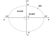
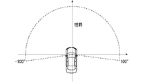
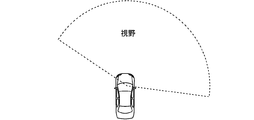
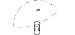
- FIG. It is a figure which shows the shape of a general field of view. It is a figure which shows the planar shape of the field of view of the driver of a vehicle. It is a figure which shows the relationship between the opening degree of an eyelid, the shape of an eyelid, and the shape of a visual field. It is a figure which shows the shape of the field of view of the driver of a vehicle when the left eye is closed. It is a figure which shows the shape of the field of view of the driver of a vehicle when the right eye is closed.
- FIG. 1 is a block diagram showing a configuration of the driving support device 10 according to the first embodiment.
- the driving support device 10 is mounted on the vehicle, and the vehicle on which the driving support device 10 is mounted is hereinafter referred to as "own vehicle".
- the driving support device 10 does not have to be permanently installed in the own vehicle, and may be realized on a portable device such as a PND (Portable Navigation Device), a mobile phone, or a smartphone that can be brought into the vehicle.
- a part or all of the functions of the driving support device 10 may be realized on a server installed outside the own vehicle and capable of communicating with the own vehicle.
- the driving support device 10 is connected to the eyelid shape detection device 21, the peripheral detection device 22, and the notification device 23 mounted on the own vehicle.
- the eyelid shape detecting device 21 detects the shape of the driver's eyelids by analyzing an image of the driver's face of the own vehicle.
- the peripheral detection device 22 is a means for detecting an object existing in the vicinity of the own vehicle, and is composed of, for example, a camera for photographing the periphery of the own vehicle, a sensor using radio waves, sound waves, light, and the like.
- the notification device 23 is a means for notifying the driver of the own vehicle, for example, a voice output device, a display device such as a CID (Center Information Display) or a HUD (Head-Up Display), or a bodily stimulus generator such as a vibrator. Etc.
- the driving support device 10 includes a visual field estimation unit 11, a caution object detection unit 12, a recognition degree estimation unit 13, and a control unit 14.
- the field of view estimation unit 11 estimates the driver's field of view based on the shape of the driver's eyelids of the own vehicle detected by the eyelid shape detecting device 21.
- the relationship between the shape of the driver's eyelids and the visual field will be explained. It is assumed that the direction of the driver's line of sight is in front of the vehicle. Further, the front direction of the own vehicle is defined as a direction having an elevation angle of 0 degrees and a horizontal angle of 0 degrees.
- the vertical angle may represent the elevation angle as a positive angle and the depression angle as a negative angle
- the horizontal angle may represent the right side as a positive angle and the left side as a negative angle.
- the field of view of a person in the normal state is generally in the range of up to 60 degrees up, up to 70 degrees down, and up to 100 degrees to the left and right, respectively. Is known to be.
- the planar shape of the driver's field of view is as shown in FIG.
- the visual field referred to here includes both an effective visual field in which an object can be recognized instantly and a peripheral visual field which is a region around the effective visual field and in which the presence or absence of an object can be confirmed.
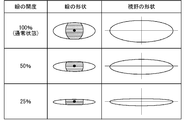
- FIG. 4 is a diagram showing the relationship between the opening degree of the eyelid, the shape of the eyelid, and the shape of the visual field.
- the state in which the upper eyelid is located between the center of the pupil and the upper end of the iris when looking at the front is defined as the normal state.
- the opening degree of the eyelid is expressed as the size of the maximum distance between the upper eyelid and the lower eyelid, where the maximum distance between the upper eyelid and the lower eyelid in the normal state is 100%.
- the state in which the eyelid opening is defined as 100% does not have to be a normal state.
- the state in which the upper and lower eyelids are located at the upper and lower ends of the iris is defined as the state in which the eyelid opening is 100%.
- a state in which the eyelid cannot be opened any more may be defined as a state in which the eyelid opening is 100%.
- the definition of eyelid opening is not limited to the above.
- the opening degree of the eyelid may be defined only by the distance between the upper eyelid and the pupil.
- the opening degree of the eyelid may be defined by the area of the area surrounded by the upper eyelid and the lower eyelid.
- the shape of the visual field is substantially similar to the shape of the region surrounded by the upper and lower eyelids, so that the shape of the visual field can be estimated from the shape of the eyelid.
- the shape of the visual field may be estimated to be an elliptical approximation of the shape of the eyelid.
- the shape of the visual field can be estimated from the opening degree of the eyelid. For example, it is estimated that when the eyelid opening is 50%, the upper visual field is 30 degrees, and when the eyelid opening is 25%, the upper visual field is 15 degrees.
- the ear side of the eyes closes first, so the left and right visual fields become slightly narrower as the eyelid opening becomes smaller. It is assumed to be constant regardless of the degree.
- the relationship between the opening of the eyelid and the visual field depends on the three-dimensional positional relationship between the eyelid and the eyeball, and the positional relationship varies from person to person (for example, the visual field of a person with a hanging upper eyelid). It will be narrower than the general field of view), but individual differences are ignored here.
- the eyelid shape detecting device 21 does not necessarily have to detect the shape of the upper eyelid and the shape of the lower eyelid of the driver, and may detect only the shape of the upper eyelid, for example. Further, the eyelid shape detecting device 21 does not directly detect the shape of the eyelid, but provides information for estimating the shape of the eyelid, such as the area of the area surrounded by the upper eyelid and the lower eyelid and the opening degree of the eyelid. May be detected. In that case, the field of view estimation unit 11 estimates the shape of the eyelid from the information acquired by the eyelid shape detecting device 21, and estimates the driver's field of view based on the estimated shape of the eyelid.
- the shape of the driver's eyelids changes, when the lighting of the oncoming vehicle or the sunlight is dazzling, the eyes are squinted to adjust the illuminance, when the driver takes a momentary reflex action, or when the eyes are itchy.
- There are various cases such as when dust gets into the eyes, when the upper eyelids are lowered due to fatigue, when the eyes are squinted to correct old eyes and astigmatism, and when the eyes are squinted due to habit.
- the shape of the eyelids also changes when the driver blinks (blinks), but the blink period is very short and does not substantially affect the driver's field of vision.
- the visual field estimation unit 11 may detect the driver's blink period and estimate the driver's visual field based on the shape of the driver's eyelids excluding the blink period. Alternatively, the visual field estimation unit 11 estimates the driver's visual field from the average value of the eyelid opening at regular intervals (for example, every 1 second), so that the blink period does not affect the estimation result of the driver's visual field. You may do so.
- the driver's field of view is not always symmetrical. Since the visual field of the right eye and the visual field of the left eye are different, if the driver moves only the eyelid of one eye, the visual field is not symmetrical. For example, when the driver closes only the left eye, the field of view on the left side becomes narrow as shown in FIG. 5, and when the driver closes only the right eye, the field of view on the right side becomes narrow as shown in FIG.
- the horizontal visual field with one eye is said to be in the range of up to 100 degrees on the ear side and up to 60 degrees on the nasal side. When the opening of the eyelid of one eye becomes small, the horizontal width of the visual field is hardly affected, but the vertical direction of the right side portion or the left side portion of the visual field becomes narrow. Therefore, it is preferable that the visual field estimation unit 11 estimates the visual field of the driver based on both the shape of the eyelid of the left eye and the shape of the eyelid of the right eye.
- the attention-requiring object detection unit 12 requires the driver of the vehicle to pay attention to the objects around the own vehicle detected by the peripheral detection device 22 that satisfy the predetermined conditions. Detect as a cautionary item. Items that fall under the category of cautionary objects include, for example, moving objects (other vehicles, bicycles, pedestrians, etc.), obstacles (edge stones, guard rails, etc.) that exist within a certain distance from the own vehicle, and the own vehicle. Moving objects (pedestrians trying to cross in front of their own vehicle, other vehicles entering the intersection at the same time as their own vehicle, etc.), traffic signs and traffic lights installed within a certain range in front of their own vehicle, and in front of their own vehicle It is possible that the vehicle has fallen on the road.
- moving objects other vehicles, bicycles, pedestrians, etc.
- obstacles edge stones, guard rails, etc.
- the recognition degree estimation unit 13 estimates the degree of recognition of the driver's attention-requiring object based on the positional relationship between the driver's visual field estimated by the visual field estimation unit 11 and the caution-required object detected by the caution-required object detection unit 12. do.
- the recognition degree estimation unit 13 has the recognition degree of the attention-requiring object outside the field of view of 0 and the field of view. It is advisable to estimate the degree of recognition of the object requiring attention inside to be 1.
- the object to be watched is a traffic light in front of the own vehicle.
- the relationship between the distance from the own vehicle to the traffic light and the direction (elevation angle) at which the traffic light can be seen by the driver is as shown in FIG. If the driver's eyelid opening is 100%, the upper field of view is 60 degrees, so if the distance from the own vehicle to the traffic light is 2.2 m or more, the traffic light is in the driver's field of view. However, when the opening of the driver's eyelids is 50%, the upper field of view is 30 degrees, so that the traffic light is out of the driver's field of view when the distance from the own vehicle to the traffic light is less than 6.6 m.
- the elevation angle of the traffic light as seen by the driver is 45 degrees.
- the positional relationship between the driver's field of view and the traffic light at this time is as shown in FIG.
- the recognition degree estimation unit 13 estimates the recognition degree of the traffic light to be 1.
- the recognition degree estimation unit 13 estimates the recognition degree of the traffic light to be 0.
- the recognition level of items requiring attention may be expressed in multiple stages or continuous numerical values. For example, when the recognition degree of the attention-requiring object is expressed by a multi-step or continuous numerical value between 0 and 1, the recognition degree estimation unit 13 estimates that the recognition degree of the attention-requiring object outside the visual field is 0. The recognition level of the object requiring attention inside the visual field is calculated based on the distance from the center of the visual field. Specifically, the recognition degree estimation unit 13 may calculate the recognition degree of the attention-requiring object so that the recognition degree becomes higher (closer to 1) as the position of the attention-requiring object is closer to the center of the visual field.
- the recognition degree estimation unit 13 may estimate the recognition degree of the attention-requiring object based on the solid angle of the attention-requiring object (corresponding to the area where the caution-required object can be seen) in the driver's field of view. For example, when the recognition degree of an object requiring attention is expressed in two stages of 0 (non-recognition) and 1 (recognition), the recognition degree estimation unit 13 has a solid angle in the visual field that is less than a predetermined threshold value. The recognition degree of the object may be estimated to be 0, and the recognition degree of the object requiring attention whose solid angle in the visual field is equal to or larger than the threshold value may be estimated to be 1. In this case, even if the object to be watched is located inside the field of view, the recognition degree may be estimated to be 0 if the solid angle is small.
- the recognition degree estimation unit 13 increases the recognition degree as the solid angle of the attention-requiring object in the driver's field of view increases.
- the degree of recognition of the object requiring attention may be calculated so that the value becomes higher (closer to 1).
- the object to be watched is a large truck approaching the own vehicle from behind.
- the tip of a large truck traveling in the left lane of the own vehicle approaches the position of 90 degrees to the left of the driver
- the positional relationship between the driver's field of view and the large truck is shown in FIG. It will be like.
- FIG. 10 As can be seen from FIG. 10, as the opening degree of the driver's eyelids increases, the driver's field of view becomes wider, so that the solid angle (area) of the large truck in the field of view also becomes larger.
- the recognition degree estimation unit 13 estimates the recognition degree of the large truck to a high value because the solid angle of the large truck in the field of view is larger as the opening degree of the driver's eyelids is larger.
- the influence of the solid angle of the object requiring attention in the visual field on the recognition degree is larger when the solid angle is smaller, and it is considered that the recognition degree is saturated when the solid angle becomes large to some extent.
- the solid angle of the heavy-duty truck will be considerably large even if the opening of the driver's eyelids is small.
- the recognition level of a large truck may be estimated to be 1 regardless of the opening degree of the driver's eyelids.
- the recognition degree estimation unit 13 estimates the recognition degree of the object to be watched by considering both the angle from the center of the driver's field of view to the object to be watched and the solid angle of the object to be watched in the driver's field of view. You may. For example, the smaller the angle from the center of the driver's field of view to the object requiring attention, the closer the position of the object requiring attention is to the effective field of view, and it may be determined that the recognition level is high. In addition, items requiring attention with bright colors are easily recognized by the driver. Therefore, the recognition degree estimation unit 13 may estimate the recognition degree of the attention-requiring object by taking into consideration the difference in hue or pattern between the attention-requiring object and its surroundings. In addition, dynamic items requiring attention are easily recognized by the driver. Therefore, the recognition degree estimation unit 13 may estimate the recognition degree of the attention-requiring object by adding the change amount or the change speed of the relative position of the attention-requiring object with respect to the own vehicle.
- the recognition degree estimation unit 13 may estimate the recognition degree of the object requiring attention in consideration of the information of the external environment of the own vehicle.
- control unit 14 provides driving support for the own vehicle based on the recognition level of the driver's attention-requiring object estimated by the recognition level estimation unit 13.
- control unit 14 controls the notification device 23 to notify the driver of the presence of the attention-requiring object when the recognition level of the driver's attention-requiring object is equal to or less than a predetermined threshold value. ..
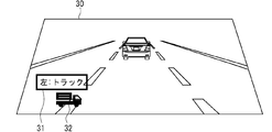
- FIG. 11 and 12 are diagrams showing an example of an image for notifying the presence of an object requiring attention when the notification device 23 is a HUD.
- the HUD can directly display the image (virtual image) in the driver's field of view.
- the control unit 14 may use the notification device 23. Is controlled so that the character message 31 and the icon 32 indicating that the truck exists on the left side are displayed near the left end of the windshield 30 as shown in FIG.
- control unit 14 may change the positions and contents of the character message 31 and the icon 32 according to the type of the object requiring attention and the driver's field of view. For example, if the object to be watched is a passenger car, the design of the icon 32 is changed to the image of the passenger car as shown in FIG. Further, for example, when the opening degree of the driver's left eye is small, the position of the character message 31 may be moved to the center of the windshield 30 as shown in FIG.
- the notification device 23 is a transmissive display device such as a HUD
- the control unit 14 displays an image that guides the driver's line of sight to the object requiring attention (for example, an image of an arrow moving in the direction of the object requiring attention). You may let me.
- a figure seen from the side of the vehicle body is used as an icon 32 indicating a vehicle requiring attention (hereinafter referred to as “vehicle requiring attention”), but the vehicle body is viewed in the front, rear, or diagonal direction. You may use the figure seen from.
- an image of the vehicle as seen by a rearview mirror may be used. In that case, a live-action image of the vehicle requiring attention taken by the rear camera of the own vehicle may be used as the icon 32.
- an image obtained by synthesizing a vehicle figure or a live-action image in an image (display object) imitating the frame of the rearview mirror may be used as the icon 32.
- the display position of the icon 32 indicating the vehicle requiring attention was constant, but it may be changed according to the position of the vehicle requiring attention.
- the display position of the icon 32 may be controlled so that the icon 32 is displayed at a position overlapping the vehicle requiring attention when viewed from the driving vehicle.
- the size of the icon 32 may be changed according to the size of the vehicle requiring attention.
- the icon 32 when the icon 32 is small, the icon 32 may be displayed at a position where the vehicle requiring attention from the driving vehicle overlaps with the traveling lane.
- the method in which the notification device 23 notifies the presence of an object requiring attention is not limited to the above example, and any method may be used.
- visual notification for example, an image of a cautionary object or a deformed image of a cautionary object may be displayed on the HUD or CID, and an alarm LED provided under the windshield of the own vehicle or on a pillar may be used. It is conceivable to turn it on.
- the HUD or CID may display an image showing the current lighting color of the traffic light, or the LED may be made to emit light in the same color as the current lighting color of the traffic light.
- a voice that notifies the status of the object requiring attention and the name of the moving object from the voice output device.
- the voice for notifying the cautioned object for example, if the cautioned object is another vehicle, a voice message such as "a large truck in the left lane is approaching" is preferable.
- the object to be watched is a traffic light, a voice message indicating the lighting color of the traffic light (for example, "blue") or a sound effect indicating that the lighting color of the traffic light has changed is preferable.
- the notification using sound field localization may be performed so that the voice can be heard from the direction in which the object requiring attention exists.
- contact-type (experience-based) notification may be performed by vibrating the handle.
- the control unit 14 may change the notification method according to the degree of recognition of the object requiring attention. In that case, it is preferable that the control unit 14 gives a notification that the driver can easily notice when the recognition level of the object requiring attention is low. For example, when the recognition level of the object requiring attention is relatively high, only visual notification may be performed, and when the recognition level is relatively low, visual notification and auditory notification may be used in combination. Further, it is preferable that the lower the recognition level of the object requiring attention, the more conspicuous the visual notification is, the more easily audible the auditory notification, and the stronger the stimulus.
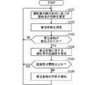
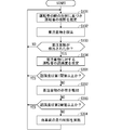
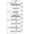
- FIG. 13 is a flowchart showing the operation of the driving support device 10 according to the first embodiment. Hereinafter, the operation of the driving support device 10 will be described with reference to this flowchart.
- the field of view estimation unit 11 estimates the driver's field of view based on the shape of the eyelid of the driver of the own vehicle detected by the eyelid shape detecting device 21 (step S101).
- the caution-required object detection unit 12 searches for the caution-required object from the objects around the own vehicle detected by the peripheral detection device 22 (step S102). If the item requiring attention is not detected at this time (NO in step S103), the process returns to step S101.
- the recognition degree estimation unit 13 detects the driver's visual field and the caution-required object detection unit 12 estimated by the visual field estimation unit 11.
- the degree of recognition of the driver's attention-requiring object is estimated based on the positional relationship with the attention-requiring object (step S104). If the estimated recognition level of the object requiring attention is equal to or higher than a predetermined threshold value (YES in step S105), the control unit 14 determines that notification is not necessary, and returns to step S101.
- step S105 If the estimated recognition level of the object requiring attention is less than the threshold value (NO in step S105), the control unit 14 controls the notification device 23 to notify the driver of the existence of the object requiring attention (step S106). After that, the process returns to step S101.
- the degree of recognition of the driver's attention-requiring object is the driver's field of view and the attention-requiring object estimated from the shape of the driver's eyelids. Estimated based on the positional relationship. Therefore, it is prevented that the estimation accuracy of the recognition degree of the attention-requiring object is lowered when the driver moves the eyelid, and as a result, the estimation accuracy of the recognition degree of the attention-requiring object is improved.
- the direction of the driver's face is assumed to be the front direction of the own vehicle, but the direction of the field of view changes depending on the direction of the face. Therefore, the driving support device 10 may be provided with a function of detecting the orientation of the driver's face, and the visual field estimation unit 11 may estimate the central direction of the driver's visual field based on the orientation of the driver's face.
- the visual field is affected by the direction of the line of sight, the visual field in the direction the eyeball is facing expands, and the visual field on the opposite side narrows. Therefore, the driving support device 10 may be provided with a function of detecting the direction of the driver's line of sight, and the field of view estimation unit 11 may estimate the driver's field of view in consideration of the direction of the driver's line of sight.
- the reason why the visual field is also affected by the direction of the line of sight is that the positional relationship between the pupil and the eyelids changes when the direction of the line of sight changes.
- the driving support device 10 may be provided with a function of detecting the positional relationship between the driver's pupil and the eyelid, and the visual field estimation unit 11 may estimate the driver's visual field in consideration of the positional relationship. Since the pupil is located at the center of the iris, the positional relationship between the pupil and the eyelid may be read as the positional relationship between the iris and the eyelid.
- the range that can be seen by gazing at the front without moving the eyes can be defined as the visual field
- the range that can be seen by moving the eyes can be defined as the visual field. do. That is, the field of view estimation unit 11 may estimate the driver's field of view based on the shape of the driver's eyelid of the own vehicle detected by the eyelid shape detecting device 21, and may consider the range of the field of view as the driver's field of view. ..
- the field of view is affected by the glasses.
- the visual field may be chipped at a portion overlapping the frame of the spectacles, or a part of the visual field may be chipped due to the refraction of light by the lens of the spectacles. Therefore, the driving support device 10 is provided with a function of detecting the shape and type of the driver's eyeglasses, or the shape and type of the driver's eyeglasses can be registered in the driving support device 10, and the visual field estimation unit 11 is the driver.
- the driver's field of view may be estimated in consideration of the shape or type of the glasses worn by the driver.
- the degree of recognition of items requiring attention is also affected by the direction of the line of sight and the direction of the face. For example, an object requiring attention near the direction of the line of sight is easy to recognize, and an object requiring attention far from the direction of the line of sight is difficult to recognize. Therefore, the recognition degree estimation unit 13 may estimate the recognition degree of the object requiring attention in consideration of the direction of the driver's line of sight or the direction of the face.
- the recognition degree estimation unit 13 may estimate the recognition degree of the object requiring attention by adding time-series data of the direction of the driver's line of sight or the direction of the face. For example, an object requiring attention that has been in the driver's field of view in the past may be treated as being recognized by the driver even if it is out of the field of view. At this time, the magnitude of the degree of recognition may be determined in consideration of the frequency and the length of time that the object requiring attention has entered the field of view in the past. If the object to be watched is a traffic light, even if the traffic light is out of the driver's field of view, the traffic light will be treated as being recognized by the driver for the same period as when the lighting color of the traffic light was in the previous field of view. When the lighting color of the traffic light changes, it may be treated that the traffic light is not recognized by the driver.
- the degree of recognition of items requiring attention is also affected by the glasses.
- the driving support device 10 may be provided with a function for detecting the shape and type of the driver's glasses, or the driving support device 10 may be able to register the shape and type of the driver's glasses, and the recognition degree estimation unit 13 may perform driving.
- the degree of recognition of the object requiring attention may be estimated in consideration of the shape or type of the glasses worn by the person.
- the caution-required object detection unit 12 may determine the caution-required degree (importance) indicating the urgency and risk (for example, the magnitude of damage at the time of contact) of the detected caution-required object. That is, it may be determined that the greater the damage expected at the time of contact, the higher the degree of caution. Further, it may be determined that the higher the contact probability is, the higher the degree of caution is required. Further, the degree of caution of the object requiring attention may be determined by considering both the magnitude of damage and the contact probability, or by adding other determination factors. For example, if the vehicle requiring attention (vehicle requiring attention) is moving irregularly, it is highly likely that the driver of the vehicle requiring attention is absent-minded or in a hurry.
- the degree of caution of the object requiring attention may be determined by considering both the magnitude of damage and the contact probability, or by adding other determination factors. For example, if the vehicle requiring attention (vehicle requiring attention) is moving irregularly, it is highly likely that the driver of the vehicle requiring attention is
- control unit 14 may change the notification method according to the degree of caution of the object requiring attention. In that case, the control unit 14 may perform notification that the driver is more likely to notice when the degree of attention required for the object requiring attention is higher. For example, when the degree of attention required is relatively low, only visual notification may be performed, and when the degree of caution is relatively high, visual notification and auditory notification may be used in combination. Further, it is preferable that the higher the degree of attention required for the object requiring attention, the more conspicuous the visual notification is, the auditory notification is performed in an easy-to-hear manner, and the contact-type notification is performed with a strong stimulus.
- FIG. 14 is a block diagram showing the configuration of the driving support device 10 according to the second embodiment.
- a vehicle control device 24 is connected to the driving support device 10 in place of the notification device 23 of FIG.
- the vehicle control device 24 is a device that automatically controls the running of the own vehicle, and is composed of, for example, an ECU (Electronic Control Unit). Since other configurations are the same as those in FIG. 1, their description will be omitted.
- ECU Electronic Control Unit
- FIG. 15 is a flowchart showing the operation of the driving support device 10 according to the second embodiment.
- the flow of FIG. 15 replaces step S106 of the flow of FIG. 13 with step S201. Since the other steps are the same as those in FIG. 13, their description will be omitted.
- Step S201 is executed when the recognition level of the object requiring attention estimated by the recognition level estimation unit 13 is less than a predetermined threshold value (NO in step S105).
- the control unit 14 controls the vehicle control device 24 to control the running of the own vehicle. After step S201, the process returns to step S101.
- step S201 The following are examples of the control executed in step S201.
- the own vehicle is once controlled so as not to go to the left.
- the unit 14 may intervene in the steering control.
- the own vehicle may be moved slightly to the right side of the center of the lane to increase the distance between the own vehicle and the heavy-duty truck and reduce the risk of contact with the heavy-duty truck.
- the control unit 14 may change the control amount of the own vehicle according to the degree of recognition of the object requiring attention or the degree of caution. That is, the control unit 14 may perform steering control of the own vehicle so that the lower the degree of recognition of the important object is, the farther the own vehicle is from the important object. Further, when the object requiring attention is a large truck, the control unit 14 controls the steering of the own vehicle so that the own vehicle is farther away from the object requiring attention than in the case of an ordinary vehicle requiring attention. May be good.
- control is performed so that the traveling speed does not exceed the speed limit once.
- Unit 14 may intervene in speed control.
- control unit 14 may control the position where the own vehicle is stopped according to the positional relationship between the driver's field of view and a traffic light or a sign which is a cautionary object. For example, when the own vehicle stops at a red light, the own vehicle should be stopped at a position where the traffic light is in the driver's field of view or near the field of view as long as it does not interfere with the running of other vehicles. , The control unit 14 may control the vehicle control device 24. For example, when the driver's upper field of view is 30 degrees, it is advisable to stop the own vehicle at a position 6.6 m or more away from the traffic light (see FIG. 7).
- FIG. 16 is a block diagram showing a configuration of the driving support device 10 according to the third embodiment.
- the vehicle control device 24 is connected to the driving support device 10. That is, both the notification device 23 shown in the first embodiment and the vehicle control device 24 shown in the second embodiment are connected to the driving support device 10. Since other configurations are the same as those in FIG. 1, their description will be omitted.
- the control unit 14 changes the content of the driving support according to the recognition level of the object requiring attention. Specifically, if the recognition level of the attention-requiring object is equal to or less than a predetermined first threshold value, the control unit 14 notifies the attention-requiring object using the notification device 23, and the recognition level of the attention-requiring object is high. If it is equal to or less than the second threshold value, which is smaller than the first threshold value, the vehicle control device 24 is used to control the running of the own vehicle in addition to the notification of the object requiring attention using the notification device 23.
- the content of the notification of the object requiring attention using the notification device 23 may be the same as that of the first embodiment, and the content of the traveling control of the own vehicle using the vehicle control device 24 may be the same as that of the second embodiment.
- FIG. 17 is a flowchart showing the operation of the driving support device 10 according to the third embodiment.
- steps S105 and S106 of the flow of FIG. 13 are replaced with steps S301 to 304. Since the other steps are the same as those in FIG. 13, their description will be omitted.
- Steps S301 to 304 are executed after step S104 in which the recognition degree estimation unit 13 estimates the recognition degree of the driver's important object.
- step S301 it is confirmed whether or not the estimated recognition level of the object requiring attention is equal to or higher than the first threshold value. If the recognition level of the object requiring attention is equal to or higher than the first threshold value (YES in step S301), the control unit 14 determines that notification is not necessary, and returns to step S101.
- step S301 If the recognition level of the item requiring attention is less than the first threshold value (NO in step S301), the process proceeds to step S302, and the control unit 14 controls the notification device 23 to notify the driver of the existence of the item requiring attention. .. Subsequently, in step S303, it is confirmed whether or not the recognition level of the object requiring attention is equal to or higher than the second threshold value. If the recognition level of the object requiring attention is equal to or higher than the second threshold value (YES in step S303), the control unit 14 determines that the traveling control of the own vehicle is not necessary, and returns to step S101.
- step S303 If the recognition level of the object requiring attention is less than the second threshold value (NO in step S303), the process proceeds to step S304, and the control unit 14 controls the vehicle control device 24 to control the running of the own vehicle. After step S304, the process returns to step S101.
- the driving support device 10 According to the driving support device 10 according to the third embodiment, it is possible to provide driving support according to the degree of recognition of the object requiring attention.
- the configuration of the driving support device 10 according to the fourth embodiment is the same as that of the third embodiment (FIG. 16).
- the control unit 14 changes the content of the driving support according to the degree of caution (importance) of the object requiring attention, which is not recognized by the driver.
- the caution level of the caution object represents the urgency and risk of the caution object (for example, the amount of damage at the time of contact is large), and is determined by the caution object detection unit 12.
- the control unit 14 notifies the caution object using the notification device 23, and the caution level of the caution object is set. If it is equal to or higher than the threshold value, the vehicle control device 24 is used to control the running of the own vehicle in addition to the notification of the object requiring attention using the notification device 23.
- the content of the notification of the object requiring attention using the notification device 23 may be the same as that of the first embodiment, and the content of the traveling control of the own vehicle using the vehicle control device 24 may be the same as that of the second embodiment.
- FIG. 18 is a flowchart showing the operation of the driving support device 10 according to the fourth embodiment.
- the flow of FIG. 18 is obtained by adding steps S401 and S402 after step S106 of the flow of FIG. Since the other steps are the same as those in FIG. 13, their description will be omitted.
- Step S401 is executed after step S106 in which the estimated recognition level of the attention-requiring object is determined to be less than the threshold value and the control unit 14 notifies the attention-requiring object using the notification device 23.
- step S401 it is confirmed whether or not the degree of caution of the object requiring attention is equal to or higher than a predetermined threshold value. If the degree of caution of the object requiring attention is less than the threshold value (NO in step S401), the control unit 14 determines that the traveling control of the own vehicle is not necessary, and returns to step S101.
- step S401 If the degree of caution of the object requiring attention is equal to or higher than the threshold value (YES in step S401), the process proceeds to step S402, and the control unit 14 controls the vehicle control device 24 to control the running of the own vehicle. After step S402, the process returns to step S101.
- the driving support device 10 According to the driving support device 10 according to the fourth embodiment, it is possible to provide driving support according to the degree of caution of the object requiring attention.
- ⁇ Hardware configuration example> 19 and 20 are diagrams showing an example of the hardware configuration of the driving support device 10, respectively.
- Each function of the component of the operation support device 10 shown in FIG. 1, FIG. 14 or FIG. 16 is realized by, for example, the processing circuit 50 shown in FIG. That is, the driving support device 10 estimates the driver's field of view based on the shape of the driver's eyelids of the vehicle, detects the object requiring attention existing around the vehicle, and sets the driver's field of view and the object requiring attention.
- a processing circuit 50 is provided for estimating the degree of recognition of the driver's attention-requiring object based on the positional relationship and providing driving support for the vehicle based on the driver's recognition degree of the attention-requiring object.
- the processing circuit 50 may be dedicated hardware, or may be a processor (Central Processing Unit (CPU), processing unit, arithmetic unit, microprocessor, microprocessor, etc.) that executes a program stored in the memory. It may be configured by using a DSP (also called a Digital Signal Processor).
- processor Central Processing Unit (CPU), processing unit, arithmetic unit, microprocessor, microprocessor, etc.
- DSP Digital Signal Processor
- the processing circuit 50 may be, for example, a single circuit, a composite circuit, a programmed processor, a parallel programmed processor, an ASIC (Application Specific Integrated Circuit), or an FPGA (Field-Programmable). GateArray), or a combination of these, etc.
- the functions of the components of the driving support device 10 may be realized by individual processing circuits, or these functions may be collectively realized by one processing circuit.
- FIG. 20 shows an example of the hardware configuration of the driving support device 10 when the processing circuit 50 is configured by using the processor 51 that executes the program.
- the functions of the components of the driving support device 10 are realized by software (software, firmware, or a combination of software and firmware).
- the software or the like is described as a program and stored in the memory 52.
- the processor 51 realizes the functions of each part by reading and executing the program stored in the memory 52. That is, when executed by the processor 51, the driving support device 10 performs a process of estimating the driver's field of view based on the shape of the driver's eyelids of the vehicle, and detects important objects existing around the vehicle.
- a memory 52 for storing a process to be executed and a program to be executed as a result is provided. In other words, it can be said that this program causes the computer to execute the procedure and method of operation of the components of the driving support device 10.
- the memory 52 is a non-volatile or non-volatile memory such as a RAM (RandomAccessMemory), a ROM (ReadOnlyMemory), a flash memory, an EPROM (ErasableProgrammableReadOnlyMemory), and an EEPROM (ElectricallyErasableProgrammableReadOnlyMemory). Volatile semiconductor memory, HDD (Hard Disk Drive), magnetic disk, flexible disk, optical disk, compact disk, mini disk, DVD (Digital Versatile Disc) and its drive device, etc., or any storage medium used in the future. You may.
- the present invention is not limited to this, and a configuration may be configured in which a part of the components of the driving support device 10 is realized by dedicated hardware and another part of the components is realized by software or the like.
- the function is realized by the processing circuit 50 as dedicated hardware, and for some other components, the processing circuit 50 as the processor 51 is stored in the memory 52. It is possible to realize the function by reading and executing it.
- the driving support device 10 can realize each of the above-mentioned functions by hardware, software, or a combination thereof.
Landscapes
- Engineering & Computer Science (AREA)
- Automation & Control Theory (AREA)
- Transportation (AREA)
- Mechanical Engineering (AREA)
- Human Computer Interaction (AREA)
- Physics & Mathematics (AREA)
- Mathematical Physics (AREA)
- Control Of Driving Devices And Active Controlling Of Vehicle (AREA)
- Traffic Control Systems (AREA)
Abstract
運転支援装置(10)において、視野推定部(11)は、車両の運転者の瞼の形状に基づいて運転者の視野を推定する。要注意物検出部(12)は、車両の周辺に存在する要注意物を検出する。認識度推定部(13)は、視野推定部(11)が推定した運転者の視野と要注意物検出部(12)が検出した要注意物との位置関係に基づいて運転者の要注意物に対する認識度を推定する。制御部(14)は、認識度推定部(13)が推定した運転者の要注意物に対する認識度に基づいて車両の運転支援を実施する。
Description
本開示は、車両の運転支援を行う運転支援装置に関するものである。
車両の周辺に存在する要注意物を運転者が認識しているか否かを、運転者の視線の方向に基づいて推定し、運転者が要注意物を認識していないと推定されたときに種々の運転支援を行う運転支援装置が提案されている(例えば下記の特許文献1,2)。ここでいう要注意物とは、車両の運転者が注意を払うべき物体を意味し、例えば、車両に接近した移動体(他の車両、自転車、歩行者など)や障害物(縁石、ガードレールなど)、車両の前方に設置された交通標識や信号機、車両の前方の道路上の落下物などが含まれる。
特許文献1,2の技術では、運転者の視野の形状(視野の広さ)が一定であることが前提となっている。しかし実際には、運転者の視野の形状は瞼の形状に依存して変化し、例えば運転者が目を細めるとその視野は上下に狭くなる。特許文献1,2の技術では、このような視野の形状の変化が考慮されていないため、運転者が瞼を動かしたときに、運転者が要注意物を認識しているか否かの判断精度が低下する。例えば、運転者が目を細めたことで頭上の要注意物である信号機の存在を認識できなかったにもかかわらず、運転者が信号機を認識していると推定され、適切な運転支援が行われないおそれがある。
本開示は以上のような課題を解決するためになされたものであり、運転者の要注意物に対する認識度を高い精度で推定可能な運転支援装置を提供することを目的とする。
本開示に係る運転支援装置は、車両の運転者の瞼の形状に基づいて運転者の視野を推定する視野推定部と、車両の周辺に存在する要注意物を検出する要注意物検出部と、運転者の視野と要注意物との位置関係に基づいて運転者の要注意物に対する認識度を推定する認識度推定部と、運転者の要注意物に対する認識度に基づいて車両の運転支援を実施する制御部と、を備える。
本開示によれば、運転者の要注意物に対する認識度は、運転者の瞼の形状から推定された運転者の視野と要注意物との位置関係に基づいて推定される。よって、運転者が瞼を動かしたときに要注意物の認識度の推定精度が低下することが防止され、その結果、要注意物の認識度の推定精度が向上する。
本開示の目的、特徴、態様、および利点は、以下の詳細な説明と添付図面とによって、より明白となる。
<実施の形態1>
図1は、実施の形態1に係る運転支援装置10の構成を示すブロック図である。本実施の形態では、運転支援装置10は車両に搭載されているものと仮定し、以下、運転支援装置10が搭載された車両を「自車両」という。ただし、運転支援装置10は自車両に常設される必要はなく、例えば、PND(Portable Navigation Device)、携帯電話、スマートフォンなど、車両に持ち込み可能な携帯型の機器上で実現されていてもよい。また、運転支援装置10の一部または全部の機能が、自車両の外部に設置され自車両と通信可能なサーバー上で実現されていてもよい。
図1は、実施の形態1に係る運転支援装置10の構成を示すブロック図である。本実施の形態では、運転支援装置10は車両に搭載されているものと仮定し、以下、運転支援装置10が搭載された車両を「自車両」という。ただし、運転支援装置10は自車両に常設される必要はなく、例えば、PND(Portable Navigation Device)、携帯電話、スマートフォンなど、車両に持ち込み可能な携帯型の機器上で実現されていてもよい。また、運転支援装置10の一部または全部の機能が、自車両の外部に設置され自車両と通信可能なサーバー上で実現されていてもよい。
図1のように、運転支援装置10は、自車両に搭載された瞼形状検出装置21、周辺検出装置22および報知装置23に接続されている。瞼形状検出装置21は、自車両の運転者の顔を撮影した画像を解析することで、運転者の瞼の形状を検出する。周辺検出装置22は、自車両の周辺に存在する物体を検出する手段であり、例えば、自車両の周辺を撮影するカメラや、電波、音波、光等を用いたセンサなどにより構成される。報知装置23は、自車両の運転者に報知を行う手段であり、例えば、音声出力装置、CID(Center Information Display)やHUD(Head-Up Display)などの表示装置、バイブレーターなどの体感刺激発生装置等により構成される。
運転支援装置10は、視野推定部11、要注意物検出部12、認識度推定部13および制御部14を備えている。
視野推定部11は、瞼形状検出装置21が検出した自車両の運転者の瞼の形状に基づいて運転者の視野を推定する。
ここで、運転者の瞼の形状と視野との関係を説明する。運転者の視線の方向を自車両の正面前方と仮定する。また、自車両の正面方向を仰角0度、水平角度0度の方向と定義する。なお、図面において、上下方向の角度は、仰角を正の角度、俯角を負の角度で表し、水平方向の角度は、右側を正の角度、左側を負の角度で表すこともある。
通常状態(目を大きく見開いたり細めたりしていない状態)での人の視野は、図2のように、概ね、上に60度まで、下に70度まで、左右にそれぞれ100度までの範囲であることが知られている。運転者の視野の平面形状は図3のようになる。なお、ここでいう視野には、瞬時に物体を認識できる有効視野と、有効視野の周辺の領域であり、物体の有無を確認できる周辺視野との両方が含まれている。
図4は、瞼の開度と、瞼の形状と、視野の形状との関係を示す図である。ここでは、正面を見たときに、瞳孔の中心と虹彩の上端との中間に上瞼が位置した状態を通常状態と定義している。また、瞼の開度を、通常状態での上瞼と下瞼との最大距離を100%として、上瞼と下瞼との最大距離の大きさ表している。瞼の開度が100%と定義される状態は、通常状態でなくてもよく、例えば、上下の瞼が虹彩の上下端に位置した状態を瞼の開度が100%の状態と定義してもよいし、瞼をこれ以上開くことができない状態を瞼の開度が100%の状態と定義されてもよい。
また、瞼の開度の定義も上記のものに限られない。一般に、人が瞼を閉じるときは先に上瞼が下がり、遅れて下瞼が上がるため、例えば、上瞼と瞳孔との間の距離のみで瞼の開度が定義されてもよい。また、上瞼と下瞼とで囲まれた領域の面積により瞼の開度が定義されてもよい。
図4から分かるように、視野の形状は、上瞼と下瞼とで囲まれた領域の形状と概ね相似した形状となるため、視野の形状は瞼の形状から推定することができる。例えば、視野の形状は瞼の形状を楕円近似したものと推定してもよい。また、瞼の形状は、瞼の開度から推定可能であるため、視野の形状は瞼の開度から推定することができる。例えば、瞼の開度が50%のときは上方視野が30度になり、瞼の開度が25%のときは上方視野が15度になると推定される。
一般に、人が瞼を閉じるときは目の耳側が先に閉じるため、瞼の開度が小さくなると左右の視野も若干狭くなるが、ここでは説明を簡単にするため、左右の視野は瞼の開度によらず一定と仮定する。また、瞼の開度と視野との関係は、瞼と眼球との3次元的な位置関係に依存し、その位置関係には個人差があるが(例えば、上瞼が垂れ下がった人の視野は一般的な視野よりも狭くなる)、ここでは個人差は無視する。
以上から分かるように、瞼形状検出装置21は、必ずしも運転者の上瞼の形状と下瞼の形状とを検出しなくてもよく、例えば上瞼の形状だけを検出してもよい。また、瞼形状検出装置21は、直接的に瞼の形状を検出せずに、上瞼と下瞼とで囲まれた領域の面積や瞼の開度など、瞼の形状を推定するための情報を検出してもよい。その場合、視野推定部11は、瞼形状検出装置21が取得した情報から瞼の形状を推定し、推定された瞼の形状に基づいて運転者の視野を推定する。
運転者の瞼の形状が変化する場面としては、対向車の照明や太陽光が眩しいときに目を細めて照度を調整するとき、瞬間的な反射行動をとるとき、眼に痒みがあるとき、眼にゴミが入ったとき、疲労により上瞼が下がったとき、老眼や乱視を矯正するために眼を細めるとき、癖で目を細めるときなど、様々である。運転者が瞬き(瞬目)をするときも瞼の形状は変化するが、瞬目期間は非常に短く、運転者の視野に実質的には影響しない。そのため、視野推定部11は、運転者の瞬目期間を検出し、瞬目期間を除く運転者の瞼の形状に基づいて運転者の視野を推定してもよい。あるいは、視野推定部11が、瞼の開度の一定期間ごと(例えば1秒間ごと)の平均値から運転者の視野を推定することで、瞬目期間が運転者の視野の推定結果に影響しないようにしてもよい。
運転者の視野は左右対称とは限らない。右目の視野と左目の視野とは異なるため、運転者が片目の瞼だけを動かすと視野は左右対称ではなくなる。例えば運転者が左目だけを閉じると、図5のように左側の視野が狭くなり、運転者が右目だけを閉じると、図6のように右側の視野が狭くなる。なお、片眼での水平視野は耳側に100度まで、鼻側に60度までの範囲と言われている。片目の瞼の開度が小さくなったときは、視野の水平方向の広さには殆ど影響しないが、視野の右側部分または左側部分の上下方向が狭くなる。よって、視野推定部11は、左目の瞼の形状と右目の瞼の形状の両方に基づいて、運転者の視野を推定することが好ましい。
図1に戻り、要注意物検出部12は、周辺検出装置22が検出した自車両の周辺の物体のうちから、予め定められた条件を満たすものを、車両の運転者が注意を払うべき要注意物として検出する。要注意物に該当するものとしては、例えば、自車両から一定距離内に存在する移動体(他車両、自転車、歩行者など)や障害物(縁石、ガードレールなど)、自車両に接近してくる移動体(自車両の前を横切ろうとする歩行者、自車両と同時に交差点に進入してくる他車両など)、自車両の前方一定範囲内に設置された交通標識や信号機、自車両の前方の道路上の落下物などが考えられる。
認識度推定部13は、視野推定部11が推定した運転者の視野と要注意物検出部12が検出した要注意物との位置関係に基づいて、運転者の要注意物に対する認識度を推定する。
例えば、要注意物の認識度を0(非認識)と1(認識)との2段階で表す場合、認識度推定部13は、視野の外側にある要注意物の認識度は0、視野の内側にある要注意物の認識度は1と推定するとよい。
ここで、要注意物が自車両の前方の信号機である場合を考える。自車両から信号機までの距離と運転者から信号機が見える方向(仰角)との関係は図7のようになる。運転者の瞼の開度が100%であれば、上方視野は60度なので、自車両から信号機までの距離が2.2m以上あれば信号機は運転者の視野に入る。しかし、運転者の瞼の開度が50%のときは、上方視野が30度になるため、自車両から信号機までの距離が6.6m未満になると信号機は運転者の視野から外れる。
例えば自車両から信号機までの距離が3.8mのとき、運転者から見た信号機の仰角は45度となる。このときの運転者の視野と信号機との位置関係は図8のようになる。図8から分かるように、運転者の瞼の開度が100%であれば、信号機は運転者の視野に入るため、認識度推定部13は、信号機の認識度を1と推定する。しかし、運転者の瞼の開度が50%であれば、信号機は運転者の視野から外れるため、認識度推定部13は、信号機の認識度を0と推定する。
要注意物の認識度は多段階または連続的な数値で表してもよい。例えば、要注意物の認識度を0~1の間の多段階または連続的な数値で表す場合、認識度推定部13は、視野の外側にある要注意物の認識度は0と推定し、視野の内側にある要注意物の認識度は視野の中心からの距離に基づいて算出する。具体的には、認識度推定部13は、要注意物の位置が視野の中心に近くなるほど認識度が高くなるように(1に近づくように)、要注意物の認識度を算出するとよい。
また、認識度推定部13は、運転者の視野における要注意物の立体角(要注意物が見える面積に相当)に基づいて要注意物の認識度を推定してもよい。例えば、要注意物の認識度を0(非認識)と1(認識)の2段階で表す場合、認識度推定部13は、視野内の立体角が予め定められた閾値未満である要注意物の認識度は0と推定し、視野内の立体角が閾値以上の要注意物の認識度は1と推定してもよい。この場合、要注意物が視野の内側に位置していても、その立体角が小さければ、認識度を0と推定されることもある。
また例えば、要注意物の認識度を0~1の間の多段階または連続的な数値で表す場合、認識度推定部13は、運転者の視野における要注意物の立体角が大きくなるほど認識度が高くなるように(1に近づくように)、要注意物の認識度を算出してもよい。
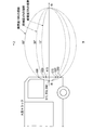
ここで、要注意物が自車両に後方から接近してきた大型トラックである場合を考える。例えば図9のように、自車両の左側の車線を走行する大型トラックの先端が運転者の左90度の位置に差し掛かった状況では、運転者の視野と大型トラックとの位置関係は図10のようになる。図10から分かるように、運転者の瞼の開度が大きくなるほど、運転者の視野が広くなるため、視野内の大型トラックの立体角(面積)も大きくなる。例えば、瞼開度100%の場合は、点A60,B60,C60で囲まれた範囲の大型トラックの一部が視野に入り、瞼開度25%の場合は、点A15,B15,C15で囲まれた範囲の大型トラックの一部が視野に入るというように、瞼開度が大きいときほど視野に入る大型トラックの立体角が大きくなる。よって、認識度推定部13は、運転者の瞼の開度が大きいときほど、視野内における大型トラックの立体角が大きいので、大型トラックの認識度を高い値に推定する。
なお、視野内の要注意物の立体角がその認識度に与える影響は、立体角が小さいときほど大きく、立体角がある程度大きくなると認識度は飽和すると考えられる。例えば大型トラックの先端が自車両の左前方30度付近にまでくれば、運転者の瞼の開度が小さくても大型トラックの立体角は相当の大きさとなるため、認識度推定部13は、運転者の瞼の開度によらず、大型トラックの認識度を1と推定してもよい。
認識度推定部13は、運転者の視野の中心から要注意物までの角度と、運転者の視野における要注意物の立体角との両方を加味して、要注意物の認識度を推定してもよい。例えば、運転者の視野の中心から要注意物までの角度が小さいほど、要注意物の位置は有効視野に近くなるので、認識度が高いと判断してもよい。また、色彩が鮮やかな要注意物は運転者に認識されやすい。そのため、認識度推定部13は、要注意物とその周辺との色相または模様の差異を加味して、要注意物の認識度を推定してもよい。また、動的な要注意物は運転者に認識されやすい。そのため、認識度推定部13は、自車両に対する要注意物の相対位置の変化量または変化速度を加味して、要注意物の認識度を推定してもよい。
また、要注意物の認識しやすさは、天候や明るさといった自車両の外部環境の影響も受ける。例えば、悪天候(雨、霧など)や夜間、対向車の照明がまぶしいときなどには、運転者は要注意物を認識しにくい。そのため、認識度推定部13は、自車両の外部環境の情報を加味して要注意物の認識度を推定してもよい。
図1に戻り、制御部14は、認識度推定部13が推定した運転者の要注意物に対する認識度に基づいて、自車両の運転支援を実施する。本実施の形態では、制御部14は、運転者の要注意物に対する認識度が予め定められた閾値以下のときに、報知装置23を制御して、運転者に要注意物の存在を報知する。
図11および図12は、報知装置23がHUDである場合における、要注意物の存在を報知するための画像の例を示す図である。HUDは自車両のウィンドシールド30に画像を表示することで、運転者の視野に画像(虚像)を直接的に表示することができる。例えば、図9のように自車両の左側方に要注意物である大型トラックが存在するにも関わらず、運転者の大型トラックに対する認識度が低い場合には、制御部14は、報知装置23を制御して、図11のように、トラックが左側方に存在する旨の文字メッセージ31やアイコン32をウィンドシールド30の左端付近に表示させる。
また、制御部14は、文字メッセージ31およびアイコン32の位置や内容を、要注意物の種別や運転者の視野に応じて変化させてもよい。例えば要注意物が乗用車であれば、図12のようにアイコン32のデザインを乗用車の画像に変更する。また、例えば運転者の左目の開度が小さいときは、図12のように文字メッセージ31の位置をウィンドシールド30の中央に移動させてもよい。また、報知装置23がHUDなどの透過型表示装置の場合、制御部14は、運転者の視線を要注意物へ誘導する画像(例えば要注意物の方向へ移動する矢印の画像など)を表示させてもよい。
なお、図11、図12では要注意物である車両(以下「要注意車両」という)を示すアイコン32として、車体を横から見た図形を用いたが、車体を前方、後方、または斜め方向から見た図形を用いてもよい。また、アイコン32として、あたかも後写鏡で見たような車両の画像を用いてもよい。その場合、自車両の後方カメラで撮影した要注意車両の実写画像を、アイコン32として用いてもよい。また、後写鏡のフレームを模した画像(表示オブジェクト)の中に車両の図形または実写画像を合成した画像を、アイコン32として用いてもよい。
また、図11、図12では、要注意車両を示すアイコン32の表示位置は一定であったが、要注意車両の位置に応じて変化させてもよい。例えば、運転車から見て要注意車両と重なる位置にアイコン32が表示されるように、アイコン32の表示位置が制御されてもよい。さらに、アイコン32の大きさを、要注意車両の大きさに応じて変化させてもよい。また、アイコン32が小さい場合には、運転車から見て要注意車両が走行中の車線と重なる位置にアイコン32が表示されるようにしてもよい。
報知装置23が要注意物の存在を報知する方法は上の例に限られず、任意の方法でよい。視覚的な報知としては、例えば、要注意物を撮影した画像や要注意物のデフォルメ画像などをHUDやCIDに表示すること、自車両のウィンドシールドの下やピラーに設けた警報用のLEDを点灯させることなどが考えられる。また、要注意物が信号機の場合は、HUDやCIDに信号機の現在の点灯色を示す画像を表示させたり、LEDを信号機の現在の点灯色と同じ色に発光させたりしてもよい。
聴覚的な報知の方法としては、要注意物の状況や移動体の名称を報知する音声を音声出力装置から出力することが考えられる。要注意物を報知する音声としては、例えば、要注意物が他の車両であれば、「左車線大型トラック接近中」などの音声メッセージが好ましい。また、要注意物が信号機であれば、信号機の点灯色を表す音声メッセージ(例えば「青です」など)や、信号機の点灯色が変わったことを表す効果音が好ましい。また、音声による報知を行う際、音声が要注意物の存在する方向から聞こえるように、音場定位を用いた報知を行ってもよい。また、ハンドルを振動させるなど接触式(体感型)の報知が行われてもよい。
制御部14は、要注意物の認識度に応じて報知の方法を変えてもよい。その場合、制御部14は、要注意物の認識度が低いときほど、運転者が気付きやすい報知を行うとよい。例えば、要注意物の認識度が比較的高いときは視覚的な報知だけを行い、認識度が比較的低いときは視覚的な報知と聴覚的な報知とを併用してもよい。また要注意物の認識度が低いときほど、視覚的な報知は目立つ態様で行われ、聴覚的な報知は聞こえやすい態様で行われ、接触式の報知は強い刺激で行われることが好ましい。
図13は、実施の形態1に係る運転支援装置10の動作を示すフローチャートである。以下、このフローチャートを参照しつつ、運転支援装置10の動作を説明する。
運転支援装置10が起動すると、視野推定部11が、瞼形状検出装置21が検出した自車両の運転者の瞼の形状に基づいて運転者の視野を推定する(ステップS101)。次に、要注意物検出部12が、周辺検出装置22が検出した自車両の周辺の物体のうちから要注意物を探索する(ステップS102)。このとき要注意物が検出されなければ(ステップS103でNO)、ステップS101へ戻る。
要注意物検出部12により要注意物が検出されれば(ステップS103でYES)、認識度推定部13が、視野推定部11が推定した運転者の視野と要注意物検出部12が検出した要注意物との位置関係に基づいて、運転者の要注意物に対する認識度を推定する(ステップS104)。推定された要注意物の認識度が予め定められた閾値以上であれば(ステップS105でYES)、制御部14は報知の必要はないと判断し、ステップS101へ戻る。
推定された要注意物の認識度が閾値未満であれば(ステップS105でNO)、制御部14は、報知装置23を制御して、運転者に要注意物の存在を報知し(ステップS106)、その後ステップS101へ戻る。
以上のように、実施の形態1に係る運転支援装置10によれば、運転者の要注意物に対する認識度が、運転者の瞼の形状から推定された運転者の視野と要注意物との位置関係に基づいて推定される。よって、運転者が瞼を動かしたときに要注意物の認識度の推定精度が低下することが防止され、その結果、要注意物の認識度の推定精度が向上する。
[変形例]
上の説明では、運転者の顔の向きを自車両の正面方向と仮定したが、視野の方向は顔の向きによって変わる。そのため、運転支援装置10に運転者の顔の向きの検出機能を持たせ、視野推定部11が、運転者の顔の向きに基づいて運転者の視野の中心方向を推定してもよい。
上の説明では、運転者の顔の向きを自車両の正面方向と仮定したが、視野の方向は顔の向きによって変わる。そのため、運転支援装置10に運転者の顔の向きの検出機能を持たせ、視野推定部11が、運転者の顔の向きに基づいて運転者の視野の中心方向を推定してもよい。
また、視野は視線の方向の影響も受け、眼球が向いた方向の視野は拡がり、その反対側の視野は狭くなる。そのため、運転支援装置10に運転者の視線方向の検出機能を持たせ、視野推定部11が、運転者の視線の方向を加味して運転者の視野を推定してもよい。視野が視線の方向の影響も受ける理由は、視線の方向が変わると瞳孔と瞼との位置関係が変わるからである。そのため、運転支援装置10に、運転者の瞳孔と瞼との位置関係の検出機能を持たせ、視野推定部11が、その位置関係を加味して運転者の視野を推定してもよい。なお、瞳孔は虹彩の中心に位置するため、瞳孔と瞼の位置関係は、虹彩と瞼の位置関係と読み替えてもよい。
また、眼を動かさずに正面を注視して見える範囲を視野、眼を動かして見える範囲を視界と定義することができるが、本明細書では両者を区別せずに視界も含めて視野として説明する。すなわち、視野推定部11は、瞼形状検出装置21が検出した自車両の運転者の瞼の形状に基づいて運転者の視界を推定し、その視界の範囲を運転者の視野とみなしてもよい。
また、視野は眼鏡の影響も受ける。例えば、眼鏡のフレームと重なる部分で視野が欠けたり、眼鏡のレンズによる光の屈折により視野の一部が欠けたりするおそれがある。そのため、運転支援装置10に運転者の眼鏡の形状や種別の検出機能を持たせる、あるいは、運転支援装置10に運転者の眼鏡の形状や種別を登録可能にし、視野推定部11が、運転者が装着している眼鏡の形状または種別を加味して運転者の視野を推定してもよい。
要注意物の認識度も、視線の方向や顔の向きの影響を受ける。例えば、視線の方向に近い位置にある要注意物は認識しやすく、視線の方向から遠い位置にある要注意物は認識しにくい。そのため、認識度推定部13は、運転者の視線の方向または顔の向きを加味して、要注意物の認識度を推定してもよい。
また、認識度推定部13は、運転者の視線の方向または顔の向きの時系列データを加味して要注意物の認識度を推定してもよい。例えば、過去に運転者の視野に入った要注意物は、視野から外れても運転者に認識されているものとして扱ってもよい。このとき、要注意物が過去に視野に入った頻度や時間の長さを加味して、その認識度の大きさを判断してもよい。要注意物が信号機である場合、信号機が運転者の視野から外れても、信号機の点灯色が前回視野に入ったときと同じ間は、当該信号機は運転者に認識されているものとして扱い、信号機の点灯色が変化すると、当該信号機は運転者に認識されていないと扱ってもよい。
また、要注意物の認識度は眼鏡の影響も受ける。例えば、眼鏡を通して見える視野の範囲は運転者の認識能力が高いが、眼鏡の外側に見える視野の範囲は認識力が低いと考えられる。そのため、運転支援装置10に運転者の眼鏡の形状や種別の検出機能を持たせる、あるいは、運転支援装置10に運転者の眼鏡の形状や種別を登録可能にし、認識度推定部13が、運転者が装着している眼鏡の形状または種別を加味して要注意物の認識度を推定してもよい。
要注意物検出部12は、検出した要注意物の緊急性やリスク(例えば接触時の被害が大きさなど)を表す要注意度(重要度)を判断してもよい。すなわち、接触時に予想される被害がより大きい要注意物ほど、要注意度が高いと判断してもよい。また、接触確率がより高い要注意物ほど、要注意度が高いと判断してもよい。また、被害の大きさと接触確率の双方を考慮したり、さらに他の判定要素を加味したりして、要注意物の要注意度を判断してもよい。例えば、要注意物である車両(要注意車両)が不規則な動きをしている場合は、要注意車両の運転者がぼんやりしている、または、慌てている可能性が高いため、その要注意車両の要注意度は高いと判断してもよい。また、制御部14は、要注意物の要注意度に応じて報知の方法を変えてもよい。その場合、制御部14は、要注意物の要注意度が高いときほど、運転者が気付きやすい報知を行うとよい。例えば、要注意物の要注意度が比較的低いときは視覚的な報知だけを行い、要注意度が比較的高いときは視覚的な報知と聴覚的な報知とを併用してもよい。また要注意物の要注意度が高いときほど、視覚的な報知は目立つ態様で行われ、聴覚的な報知は聞こえやすい態様で行われ、接触式の報知は強い刺激で行われることが好ましい。
<実施の形態2>
図14は、実施の形態2に係る運転支援装置10の構成を示すブロック図である。図14では、運転支援装置10に、図1の報知装置23に代えて、車両制御装置24が接続されている。車両制御装置24は、自車両の自動走行制御を行う装置であり、例えばECU(Electronic Control Unit)などで構成される。その他の構成は、図1と同様であるため、それらの説明は省略する。
図14は、実施の形態2に係る運転支援装置10の構成を示すブロック図である。図14では、運転支援装置10に、図1の報知装置23に代えて、車両制御装置24が接続されている。車両制御装置24は、自車両の自動走行制御を行う装置であり、例えばECU(Electronic Control Unit)などで構成される。その他の構成は、図1と同様であるため、それらの説明は省略する。
図15は、実施の形態2に係る運転支援装置10の動作を示すフローチャートである。図15のフローは、図13のフローのステップS106を、ステップS201に置き換えたものである。その他のステップは、図13と同様であるため、それらの説明は省略する。
ステップS201は、認識度推定部13が推定した要注意物の認識度が予め定められた閾値未満であるとき(ステップS105でNOのとき)に実行される。ステップS201では、制御部14が、車両制御装置24を制御して自車両の走行制御を実施する。ステップS201の後はステップS101へ戻る。
ステップS201で実行される制御の例としては、以下のものがある。例えば、図9のように、要注意物である大型トラックが自車両の左横に差し掛かった状況では、運転者が左にハンドルを切っても、一旦、自車両が左へ行かないように制御部14が操舵制御に介入するとよい。また、自車両を車線の中心よりやや右側に寄せ、自車両と大型トラックとの間隔を大きくし、大型トラックとの接触リスクを低減させてもよい。
このとき、制御部14は、要注意物の認識度または要注意度に応じて自車両の制御量を変化させてもよい。すなわち、要注意物の認識度が低いときほど、自車両が要注意物から大きく遠ざかるように、制御部14が自車両の操舵制御を行ってもよい。また、要注意物が大型トラックである場合には、要注意物の普通車である場合よりも、自車両が要注意物から大きく遠ざかるように、制御部14が自車両の操舵制御を行ってもよい。
また、運転者が要注意物である速度規制の標識を認識しておらず、自車両の走行速度が制限速度を超えそうな場合には、一旦、走行速度が制限速度を超えないように制御部14が速度制御に介入してもよい。
また、制御部14は、運転者の視野と要注意物である信号機や標識との位置関係に応じて自車両を停止させる位置を制御してもよい。例えば、自車両が赤信号で停止する際に、他の車両の走行を妨げない範囲で、信号機が運転者の視野に入るような位置、または、視野に近い位置に自車両を停止させるように、制御部14が車両制御装置24を制御してもよい。例えば、運転者の上方視野が30度のときは、自車両を信号機から6.6m以上離れた位置に停止させるとよい(図7参照)。ただし、自車両を信号機から6.6m以上離れた位置に停止させると前方の車両との車間距離が不自然に大きくなるときは、常識の範囲内で、できるだけ信号機から6.6mの位置に近い位置に自車両を停止させるとよい。
<実施の形態3>
図16は、実施の形態3に係る運転支援装置10の構成を示すブロック図である。図16では、図1の構成に加えて、運転支援装置10に車両制御装置24が接続されている。すなわち、運転支援装置10には、実施の形態1で示した報知装置23と、実施の形態2で示した車両制御装置24の両方が接続されている。その他の構成は、図1と同様であるため、それらの説明は省略する。
図16は、実施の形態3に係る運転支援装置10の構成を示すブロック図である。図16では、図1の構成に加えて、運転支援装置10に車両制御装置24が接続されている。すなわち、運転支援装置10には、実施の形態1で示した報知装置23と、実施の形態2で示した車両制御装置24の両方が接続されている。その他の構成は、図1と同様であるため、それらの説明は省略する。
実施の形態3では、制御部14は、要注意物の認識度に応じて運転支援の内容を変更する。具体的には、要注意物の認識度が予め定められた第1閾値以下であれば、制御部14は、報知装置23を用いた要注意物の報知を行い、要注意物の認識度が第1閾値よりも小さい第2閾値以下であれば、報知装置23を用いた要注意物の報知に加え、車両制御装置24を用いた自車両の走行制御を行う。なお、報知装置23を用いた要注意物の報知の内容は、実施の形態1と同様でよく、車両制御装置24を用いた自車両の走行制御の内容は実施の形態2と同様でよい。
図17は、実施の形態3に係る運転支援装置10の動作を示すフローチャートである。図17のフローは、図13のフローのステップS105,S106を、ステップS301~304に置き換えたものである。その他のステップは、図13と同様であるため、それらの説明は省略する。
ステップS301~304は、認識度推定部13が運転者の要注意物に対する認識度を推定するステップS104の後に実行される。ステップS301では、推定された要注意物の認識度が第1閾値以上か否かが確認される。要注意物の認識度が第1閾値以上であれば(ステップS301でYES)、制御部14は報知の必要はないと判断し、ステップS101へ戻る。
要注意物の認識度が第1閾値未満であれば(ステップS301でNO)、ステップS302へ進み、制御部14は、報知装置23を制御して、運転者に要注意物の存在を報知する。続いて、ステップS303では、要注意物の認識度が第2閾値以上か否かが確認される。要注意物の認識度が第2閾値以上であれば(ステップS303でYES)、制御部14は自車両の走行制御の必要はないと判断し、ステップS101へ戻る。
要注意物の認識度が第2閾値未満であれば(ステップS303でNO)、ステップS304へ進み、制御部14は、車両制御装置24を制御して自車両の走行制御を実施する。ステップS304の後はステップS101へ戻る。
実施の形態3に係る運転支援装置10によれば、要注意物の認識度に応じた内容の運転支援を実施することが可能である。
<実施の形態4>
実施の形態4に係る運転支援装置10の構成は、実施の形態3(図16)と同様である。実施の形態4では、制御部14は、運転者の認識度が低い要注意物の要注意度(重要度)に応じて運転支援の内容を変更する。要注意物の要注意度は、要注意物の緊急性やリスク(例えば接触時の被害が大きさなど)を表すものであり、要注意物検出部12により判断される。
実施の形態4に係る運転支援装置10の構成は、実施の形態3(図16)と同様である。実施の形態4では、制御部14は、運転者の認識度が低い要注意物の要注意度(重要度)に応じて運転支援の内容を変更する。要注意物の要注意度は、要注意物の緊急性やリスク(例えば接触時の被害が大きさなど)を表すものであり、要注意物検出部12により判断される。
具体的には、要注意物の要注意度が予め定められた閾値未満であれば、制御部14は、報知装置23を用いた要注意物の報知を行い、要注意物の要注意度が閾値以上であれば、報知装置23を用いた要注意物の報知に加え、車両制御装置24を用いた自車両の走行制御を行う。なお、報知装置23を用いた要注意物の報知の内容は、実施の形態1と同様でよく、車両制御装置24を用いた自車両の走行制御の内容は実施の形態2と同様でよい。
図18は、実施の形態4に係る運転支援装置10の動作を示すフローチャートである。図18のフローは、図13のフローのステップS106の後に、ステップS401,S402を追加したものである。その他のステップは、図13と同様であるため、それらの説明は省略する。
ステップS401は、推定された要注意物の認識度が閾値未満と判断されて、制御部14が報知装置23を用いた要注意物の報知を行うステップS106の後に実行される。ステップS401では、要注意物の要注意度が予め定められた閾値以上か否かが確認される。要注意物の要注意度が閾値未満であれば(ステップS401でNO)、制御部14は自車両の走行制御の必要はないと判断し、ステップS101へ戻る。
要注意物の要注意度が閾値以上であれば(ステップS401でYES)、ステップS402へ進み、制御部14は、車両制御装置24を制御して自車両の走行制御を実施する。ステップS402の後はステップS101へ戻る。
実施の形態4に係る運転支援装置10によれば、要注意物の要注意度に応じた内容の運転支援を実施することが可能である。
<ハードウェア構成例>
図19および図20は、それぞれ運転支援装置10のハードウェア構成の例を示す図である。図1、図14または図16に示した運転支援装置10の構成要素の各機能は、例えば図19に示す処理回路50により実現される。すなわち、運転支援装置10は、車両の運転者の瞼の形状に基づいて運転者の視野を推定し、車両の周辺に存在する要注意物を検出し、運転者の視野と要注意物との位置関係に基づいて運転者の要注意物に対する認識度を推定し、運転者の要注意物に対する認識度に基づいて車両の運転支援を実施する、ための処理回路50を備える。処理回路50は、専用のハードウェアであってもよいし、メモリに格納されたプログラムを実行するプロセッサ(中央処理装置(CPU:Central Processing Unit)、処理装置、演算装置、マイクロプロセッサ、マイクロコンピュータ、DSP(Digital Signal Processor)とも呼ばれる)を用いて構成されていてもよい。
図19および図20は、それぞれ運転支援装置10のハードウェア構成の例を示す図である。図1、図14または図16に示した運転支援装置10の構成要素の各機能は、例えば図19に示す処理回路50により実現される。すなわち、運転支援装置10は、車両の運転者の瞼の形状に基づいて運転者の視野を推定し、車両の周辺に存在する要注意物を検出し、運転者の視野と要注意物との位置関係に基づいて運転者の要注意物に対する認識度を推定し、運転者の要注意物に対する認識度に基づいて車両の運転支援を実施する、ための処理回路50を備える。処理回路50は、専用のハードウェアであってもよいし、メモリに格納されたプログラムを実行するプロセッサ(中央処理装置(CPU:Central Processing Unit)、処理装置、演算装置、マイクロプロセッサ、マイクロコンピュータ、DSP(Digital Signal Processor)とも呼ばれる)を用いて構成されていてもよい。
処理回路50が専用のハードウェアである場合、処理回路50は、例えば、単一回路、複合回路、プログラム化したプロセッサ、並列プログラム化したプロセッサ、ASIC(Application Specific Integrated Circuit)、FPGA(Field-Programmable Gate Array)、またはこれらを組み合わせたものなどが該当する。運転支援装置10の構成要素の各々の機能が個別の処理回路で実現されてもよいし、それらの機能がまとめて一つの処理回路で実現されてもよい。
図20は、処理回路50がプログラムを実行するプロセッサ51を用いて構成されている場合における運転支援装置10のハードウェア構成の例を示している。この場合、運転支援装置10の構成要素の機能は、ソフトウェア等(ソフトウェア、ファームウェア、またはソフトウェアとファームウェアとの組み合わせ)により実現される。ソフトウェア等はプログラムとして記述され、メモリ52に格納される。プロセッサ51は、メモリ52に記憶されたプログラムを読み出して実行することにより、各部の機能を実現する。すなわち、運転支援装置10は、プロセッサ51により実行されるときに、車両の運転者の瞼の形状に基づいて運転者の視野を推定する処理と、車両の周辺に存在する要注意物を検出する処理と、運転者の視野と要注意物との位置関係に基づいて運転者の要注意物に対する認識度を推定する処理と、運転者の要注意物に対する認識度に基づいて車両の運転支援を実施する処理と、が結果的に実行されることになるプログラムを格納するためのメモリ52を備える。換言すれば、このプログラムは、運転支援装置10の構成要素の動作の手順や方法をコンピュータに実行させるものであるともいえる。
ここで、メモリ52は、例えば、RAM(Random Access Memory)、ROM(Read Only Memory)、フラッシュメモリ、EPROM(Erasable Programmable Read Only Memory)、EEPROM(Electrically Erasable Programmable Read Only Memory)などの、不揮発性または揮発性の半導体メモリ、HDD(Hard Disk Drive)、磁気ディスク、フレキシブルディスク、光ディスク、コンパクトディスク、ミニディスク、DVD(Digital Versatile Disc)およびそのドライブ装置等、または、今後使用されるあらゆる記憶媒体であってもよい。
以上、運転支援装置10の構成要素の機能が、ハードウェアおよびソフトウェア等のいずれか一方で実現される構成について説明した。しかしこれに限ったものではなく、運転支援装置10の一部の構成要素を専用のハードウェアで実現し、別の一部の構成要素をソフトウェア等で実現する構成であってもよい。例えば、一部の構成要素については専用のハードウェアとしての処理回路50でその機能を実現し、他の一部の構成要素についてはプロセッサ51としての処理回路50がメモリ52に格納されたプログラムを読み出して実行することによってその機能を実現することが可能である。
以上のように、運転支援装置10は、ハードウェア、ソフトウェア等、またはこれらの組み合わせによって、上述の各機能を実現することができる。
なお、各実施の形態を自由に組み合わせたり、各実施の形態を適宜、変形、省略したりすることが可能である。
上記した説明は、すべての態様において、例示であって、例示されていない無数の変形例が想定され得るものと解される。
10 運転支援装置、11 視野推定部、12 要注意物検出部、13 認識度推定部、14 制御部、21 瞼形状検出装置、22 周辺検出装置、23 報知装置、24 車両制御装置、30 ウィンドシールド、31 文字メッセージ、32 アイコン、50 処理回路、51 プロセッサ、52 メモリ。
Claims (22)
- 車両の運転者の瞼の形状に基づいて前記運転者の視野を推定する視野推定部と、
前記車両の周辺に存在する要注意物を検出する要注意物検出部と、
前記運転者の前記視野と前記要注意物との位置関係に基づいて前記運転者の前記要注意物に対する認識度を推定する認識度推定部と、
前記運転者の前記要注意物に対する前記認識度に基づいて前記車両の運転支援を実施する制御部と、
を備える運転支援装置。 - 前記視野推定部は、瞬目期間を除く前記運転者の前記瞼の形状に基づいて前記運転者の前記視野を推定する、
請求項1に記載の運転支援装置。 - 前記視野推定部は、前記運転者の上瞼の形状に基づいて前記運転者の前記視野を推定する、
請求項1に記載の運転支援装置。 - 前記視野推定部は、前記運転者の上瞼と下瞼とで囲まれた領域の面積から瞼の形状を推定し、推定された瞼の形状に基づいて前記運転者の前記視野を推定する、
請求項1に記載の運転支援装置。 - 前記視野推定部は、前記運転者の瞼の開度から瞼の形状を推定し、推定された瞼の形状に基づいて前記運転者の前記視野を推定する、
請求項1に記載の運転支援装置。 - 前記視野推定部は、左目の瞼の形状と右目の瞼の形状とに基づいて前記運転者の前記視野を推定する、
請求項1に記載の運転支援装置。 - 前記視野推定部は、前記運転者の顔の向きに基づいて前記運転者の前記視野の中心方向を推定する、
請求項1に記載の運転支援装置。 - 前記視野推定部は、前記運転者の視線の方向または虹彩と瞼との位置関係を加味して前記運転者の前記視野を推定する、
請求項1に記載の運転支援装置。 - 前記視野推定部は、前記運転者が装着している眼鏡の形状または種別を加味して前記運転者の前記視野を推定する、
請求項1に記載の運転支援装置。 - 前記認識度推定部は、前記運転者の前記視野における、前記視野の中心から前記要注意物までの距離を加味して前記要注意物の前記認識度を推定する、
請求項1に記載の運転支援装置。 - 前記認識度推定部は、前記運転者の前記視野における前記要注意物の立体角を加味して前記要注意物の前記認識度を推定する、
請求項1に記載の運転支援装置。 - 前記認識度推定部は、前記運転者の視線の方向または顔の向きの時系列データを加味して前記要注意物の前記認識度を推定する、
請求項1に記載の運転支援装置。 - 前記認識度推定部は、前記車両に対する前記要注意物の位置の変化量または変化速度を加味して前記要注意物の前記認識度を推定する、
請求項1に記載の運転支援装置。 - 前記認識度推定部は、前記要注意物とその周辺との色相または模様の差異を加味して前記要注意物の前記認識度を推定する、
請求項1に記載の運転支援装置。 - 前記認識度推定部は、前記車両の外部環境の情報を加味して前記要注意物の前記認識度を推定する、
請求項1に記載の運転支援装置。 - 前記認識度推定部は、前記運転者が装着している眼鏡の形状または種別を加味して前記要注意物の前記認識度を推定する、
請求項1に記載の運転支援装置。 - 前記制御部は、前記要注意物の前記認識度が予め定められた閾値以下のとき、前記運転者に前記要注意物の存在を報知する、
請求項1に記載の運転支援装置。 - 前記制御部は、前記認識度が予め定められた閾値以下の前記要注意物である障害物を避けるように前記車両を制御する、
請求項1に記載の運転支援装置。 - 前記制御部は、前記認識度が予め定められた閾値以下の前記要注意物である信号機が赤信号のときに、前記車両を停止させる位置を制御する、
請求項1に記載の運転支援装置。 - 前記制御部は、前記要注意物の前記認識度に応じて前記運転支援の内容を変更する、
請求項1に記載の運転支援装置。 - 前記要注意物検出部は、前記要注意物の種別および前記車両との位置関係に基づいて、前記要注意物の要注意度を判断し、
前記制御部は、前記要注意物の前記要注意度に応じて前記運転支援の内容を変更する、
請求項1に記載の運転支援装置。 - 運転支援装置の視野推定部が、車両の運転者の瞼の形状に基づいて前記運転者の視野を推定し、
前記運転支援装置の要注意物検出部が、前記車両の周辺に存在する要注意物を検出し、
前記運転支援装置の認識度推定部が、前記運転者の前記視野と前記要注意物との位置関係に基づいて前記運転者の前記要注意物に対する認識度を推定し、
前記運転支援装置の制御部が、前記運転者の前記要注意物に対する前記認識度に基づいて前記車両の運転支援を実施する、
運転支援方法。
Priority Applications (2)
| Application Number | Priority Date | Filing Date | Title |
|---|---|---|---|
| JP2022534529A JP7286021B2 (ja) | 2020-07-07 | 2020-07-07 | 運転支援装置および運転支援方法 |
| PCT/JP2020/026548 WO2022009303A1 (ja) | 2020-07-07 | 2020-07-07 | 運転支援装置および運転支援方法 |
Applications Claiming Priority (1)
| Application Number | Priority Date | Filing Date | Title |
|---|---|---|---|
| PCT/JP2020/026548 WO2022009303A1 (ja) | 2020-07-07 | 2020-07-07 | 運転支援装置および運転支援方法 |
Publications (1)
| Publication Number | Publication Date |
|---|---|
| WO2022009303A1 true WO2022009303A1 (ja) | 2022-01-13 |
Family
ID=79552308
Family Applications (1)
| Application Number | Title | Priority Date | Filing Date |
|---|---|---|---|
| PCT/JP2020/026548 Ceased WO2022009303A1 (ja) | 2020-07-07 | 2020-07-07 | 運転支援装置および運転支援方法 |
Country Status (2)
| Country | Link |
|---|---|
| JP (1) | JP7286021B2 (ja) |
| WO (1) | WO2022009303A1 (ja) |
Citations (5)
| Publication number | Priority date | Publication date | Assignee | Title |
|---|---|---|---|---|
| JP2001357498A (ja) * | 2000-06-15 | 2001-12-26 | Mazda Motor Corp | 車両用情報提供装置 |
| JP2017004043A (ja) * | 2015-06-04 | 2017-01-05 | マツダ株式会社 | 運転者状態判定方法及びその判定装置 |
| WO2018008085A1 (ja) * | 2016-07-05 | 2018-01-11 | 三菱電機株式会社 | 認知領域推定装置、認知領域推定方法および認知領域推定プログラム |
| JP2019008800A (ja) * | 2018-06-25 | 2019-01-17 | 株式会社デンソー | ドライバの運転不能状態検出装置 |
| JP2019087170A (ja) * | 2017-11-10 | 2019-06-06 | アルパイン株式会社 | 瞼開閉判定装置および眠気検知装置 |
Family Cites Families (1)
| Publication number | Priority date | Publication date | Assignee | Title |
|---|---|---|---|---|
| JP7016211B2 (ja) * | 2016-08-05 | 2022-02-04 | 株式会社コーエーテクモゲームス | 演出処理プログラム及び情報処理装置 |
-
2020
- 2020-07-07 JP JP2022534529A patent/JP7286021B2/ja active Active
- 2020-07-07 WO PCT/JP2020/026548 patent/WO2022009303A1/ja not_active Ceased
Patent Citations (5)
| Publication number | Priority date | Publication date | Assignee | Title |
|---|---|---|---|---|
| JP2001357498A (ja) * | 2000-06-15 | 2001-12-26 | Mazda Motor Corp | 車両用情報提供装置 |
| JP2017004043A (ja) * | 2015-06-04 | 2017-01-05 | マツダ株式会社 | 運転者状態判定方法及びその判定装置 |
| WO2018008085A1 (ja) * | 2016-07-05 | 2018-01-11 | 三菱電機株式会社 | 認知領域推定装置、認知領域推定方法および認知領域推定プログラム |
| JP2019087170A (ja) * | 2017-11-10 | 2019-06-06 | アルパイン株式会社 | 瞼開閉判定装置および眠気検知装置 |
| JP2019008800A (ja) * | 2018-06-25 | 2019-01-17 | 株式会社デンソー | ドライバの運転不能状態検出装置 |
Also Published As
| Publication number | Publication date |
|---|---|
| JPWO2022009303A1 (ja) | 2022-01-13 |
| JP7286021B2 (ja) | 2023-06-02 |
Similar Documents
| Publication | Publication Date | Title |
|---|---|---|
| US11887562B2 (en) | Automated adjustment of head up display image in a vehicle | |
| JPWO2015025350A1 (ja) | 車載表示制御装置 | |
| US10861336B2 (en) | Monitoring drivers and external environment for vehicles | |
| WO2014097347A1 (ja) | 視認性推定装置、視認性推定方法、及び安全運転支援システム | |
| JP2016103249A (ja) | 運転支援装置および運転支援方法 | |
| US11847840B2 (en) | Visual notification of distracted driving | |
| CN107650639B (zh) | 视野控制装置 | |
| CN111098864B (zh) | 提示方法、装置、自动驾驶车辆及存储介质 | |
| JP2004030212A (ja) | 車両用情報提供装置 | |
| CN105691390A (zh) | 一种车辆预警装置和预警方法 | |
| JP2022142614A (ja) | 安全確認支援装置、安全確認支援方法及び安全確認支援プログラム | |
| WO2021221013A1 (ja) | 制御装置 | |
| CN104299400A (zh) | 车辆周围环境监测系统 | |
| CN111086518B (zh) | 显示方法、装置、车载平视显示设备及存储介质 | |
| JP2019012454A (ja) | ドライバ監視支援装置、ドライバ監視支援制御装置、ドライバ監視支援方法、及びドライバ監視支援装置制御方法 | |
| JP7286021B2 (ja) | 運転支援装置および運転支援方法 | |
| CN116022158B (zh) | 多域控制器协作的驾驶安全控制方法及装置 | |
| JP2018097479A (ja) | 運転支援装置、運転支援方法、運転支援プログラム、及び運転支援システム | |
| JP6946962B2 (ja) | 走行支援装置及びコンピュータプログラム | |
| JP7294483B2 (ja) | 運転支援装置、運転支援方法及びプログラム | |
| JP2025012903A (ja) | ドライバモニタ装置、ドライバモニタ方法及びドライバモニタ用コンピュータプログラム | |
| JP2022133688A (ja) | 運転支援装置および運転支援方法 | |
| WO2021199244A1 (ja) | 車両用調光装置および調光方法 | |
| TWI753419B (zh) | 以視線追蹤達成駕駛習慣養成的裝置及方法 | |
| JP7185571B2 (ja) | 視認方向推定装置、視認方向推定方法、およびプログラム |
Legal Events
| Date | Code | Title | Description |
|---|---|---|---|
| 121 | Ep: the epo has been informed by wipo that ep was designated in this application |
Ref document number: 20944790 Country of ref document: EP Kind code of ref document: A1 |
|
| ENP | Entry into the national phase |
Ref document number: 2022534529 Country of ref document: JP Kind code of ref document: A |
|
| NENP | Non-entry into the national phase |
Ref country code: DE |
|
| 122 | Ep: pct application non-entry in european phase |
Ref document number: 20944790 Country of ref document: EP Kind code of ref document: A1 |