WO2022009019A1 - 電極、二次電池、移動体および電子機器 - Google Patents
電極、二次電池、移動体および電子機器 Download PDFInfo
- Publication number
- WO2022009019A1 WO2022009019A1 PCT/IB2021/055785 IB2021055785W WO2022009019A1 WO 2022009019 A1 WO2022009019 A1 WO 2022009019A1 IB 2021055785 W IB2021055785 W IB 2021055785W WO 2022009019 A1 WO2022009019 A1 WO 2022009019A1
- Authority
- WO
- WIPO (PCT)
- Prior art keywords
- secondary battery
- graphene
- active material
- particles
- positive electrode
- Prior art date
- Legal status (The legal status is an assumption and is not a legal conclusion. Google has not performed a legal analysis and makes no representation as to the accuracy of the status listed.)
- Ceased
Links
Images


Classifications
-
- H—ELECTRICITY
- H01—ELECTRIC ELEMENTS
- H01M—PROCESSES OR MEANS, e.g. BATTERIES, FOR THE DIRECT CONVERSION OF CHEMICAL ENERGY INTO ELECTRICAL ENERGY
- H01M4/00—Electrodes
- H01M4/02—Electrodes composed of, or comprising, active material
- H01M4/36—Selection of substances as active materials, active masses, active liquids
- H01M4/58—Selection of substances as active materials, active masses, active liquids of inorganic compounds other than oxides or hydroxides, e.g. sulfides, selenides, tellurides, halogenides or LiCoFy; of polyanionic structures, e.g. phosphates, silicates or borates
- H01M4/583—Carbonaceous material, e.g. graphite-intercalation compounds or CFx
- H01M4/587—Carbonaceous material, e.g. graphite-intercalation compounds or CFx for inserting or intercalating light metals
-
- H—ELECTRICITY
- H01—ELECTRIC ELEMENTS
- H01M—PROCESSES OR MEANS, e.g. BATTERIES, FOR THE DIRECT CONVERSION OF CHEMICAL ENERGY INTO ELECTRICAL ENERGY
- H01M4/00—Electrodes
- H01M4/02—Electrodes composed of, or comprising, active material
- H01M4/36—Selection of substances as active materials, active masses, active liquids
- H01M4/48—Selection of substances as active materials, active masses, active liquids of inorganic oxides or hydroxides
- H01M4/483—Selection of substances as active materials, active masses, active liquids of inorganic oxides or hydroxides for non-aqueous cells
-
- H—ELECTRICITY
- H01—ELECTRIC ELEMENTS
- H01G—CAPACITORS; CAPACITORS, RECTIFIERS, DETECTORS, SWITCHING DEVICES, LIGHT-SENSITIVE OR TEMPERATURE-SENSITIVE DEVICES OF THE ELECTROLYTIC TYPE
- H01G11/00—Hybrid capacitors, i.e. capacitors having different positive and negative electrodes; Electric double-layer [EDL] capacitors; Processes for the manufacture thereof or of parts thereof
- H01G11/04—Hybrid capacitors
- H01G11/06—Hybrid capacitors with one of the electrodes allowing ions to be reversibly doped thereinto, e.g. lithium ion capacitors [LIC]
-
- H—ELECTRICITY
- H01—ELECTRIC ELEMENTS
- H01G—CAPACITORS; CAPACITORS, RECTIFIERS, DETECTORS, SWITCHING DEVICES, LIGHT-SENSITIVE OR TEMPERATURE-SENSITIVE DEVICES OF THE ELECTROLYTIC TYPE
- H01G11/00—Hybrid capacitors, i.e. capacitors having different positive and negative electrodes; Electric double-layer [EDL] capacitors; Processes for the manufacture thereof or of parts thereof
- H01G11/22—Electrodes
- H01G11/30—Electrodes characterised by their material
-
- H—ELECTRICITY
- H01—ELECTRIC ELEMENTS
- H01M—PROCESSES OR MEANS, e.g. BATTERIES, FOR THE DIRECT CONVERSION OF CHEMICAL ENERGY INTO ELECTRICAL ENERGY
- H01M10/00—Secondary cells; Manufacture thereof
- H01M10/05—Accumulators with non-aqueous electrolyte
- H01M10/052—Li-accumulators
-
- H—ELECTRICITY
- H01—ELECTRIC ELEMENTS
- H01M—PROCESSES OR MEANS, e.g. BATTERIES, FOR THE DIRECT CONVERSION OF CHEMICAL ENERGY INTO ELECTRICAL ENERGY
- H01M10/00—Secondary cells; Manufacture thereof
- H01M10/05—Accumulators with non-aqueous electrolyte
- H01M10/052—Li-accumulators
- H01M10/0525—Rocking-chair batteries, i.e. batteries with lithium insertion or intercalation in both electrodes; Lithium-ion batteries
-
- H—ELECTRICITY
- H01—ELECTRIC ELEMENTS
- H01M—PROCESSES OR MEANS, e.g. BATTERIES, FOR THE DIRECT CONVERSION OF CHEMICAL ENERGY INTO ELECTRICAL ENERGY
- H01M4/00—Electrodes
- H01M4/02—Electrodes composed of, or comprising, active material
- H01M4/13—Electrodes for accumulators with non-aqueous electrolyte, e.g. for lithium-accumulators; Processes of manufacture thereof
- H01M4/133—Electrodes based on carbonaceous material, e.g. graphite-intercalation compounds or CFx
-
- H—ELECTRICITY
- H01—ELECTRIC ELEMENTS
- H01M—PROCESSES OR MEANS, e.g. BATTERIES, FOR THE DIRECT CONVERSION OF CHEMICAL ENERGY INTO ELECTRICAL ENERGY
- H01M4/00—Electrodes
- H01M4/02—Electrodes composed of, or comprising, active material
- H01M4/13—Electrodes for accumulators with non-aqueous electrolyte, e.g. for lithium-accumulators; Processes of manufacture thereof
- H01M4/134—Electrodes based on metals, Si or alloys
-
- H—ELECTRICITY
- H01—ELECTRIC ELEMENTS
- H01M—PROCESSES OR MEANS, e.g. BATTERIES, FOR THE DIRECT CONVERSION OF CHEMICAL ENERGY INTO ELECTRICAL ENERGY
- H01M4/00—Electrodes
- H01M4/02—Electrodes composed of, or comprising, active material
- H01M4/36—Selection of substances as active materials, active masses, active liquids
- H01M4/362—Composites
- H01M4/364—Composites as mixtures
-
- H—ELECTRICITY
- H01—ELECTRIC ELEMENTS
- H01M—PROCESSES OR MEANS, e.g. BATTERIES, FOR THE DIRECT CONVERSION OF CHEMICAL ENERGY INTO ELECTRICAL ENERGY
- H01M4/00—Electrodes
- H01M4/02—Electrodes composed of, or comprising, active material
- H01M4/36—Selection of substances as active materials, active masses, active liquids
- H01M4/362—Composites
- H01M4/366—Composites as layered products
-
- H—ELECTRICITY
- H01—ELECTRIC ELEMENTS
- H01M—PROCESSES OR MEANS, e.g. BATTERIES, FOR THE DIRECT CONVERSION OF CHEMICAL ENERGY INTO ELECTRICAL ENERGY
- H01M4/00—Electrodes
- H01M4/02—Electrodes composed of, or comprising, active material
- H01M4/36—Selection of substances as active materials, active masses, active liquids
- H01M4/38—Selection of substances as active materials, active masses, active liquids of elements or alloys
- H01M4/386—Silicon or alloys based on silicon
-
- H—ELECTRICITY
- H01—ELECTRIC ELEMENTS
- H01M—PROCESSES OR MEANS, e.g. BATTERIES, FOR THE DIRECT CONVERSION OF CHEMICAL ENERGY INTO ELECTRICAL ENERGY
- H01M4/00—Electrodes
- H01M4/02—Electrodes composed of, or comprising, active material
- H01M4/36—Selection of substances as active materials, active masses, active liquids
- H01M4/58—Selection of substances as active materials, active masses, active liquids of inorganic compounds other than oxides or hydroxides, e.g. sulfides, selenides, tellurides, halogenides or LiCoFy; of polyanionic structures, e.g. phosphates, silicates or borates
- H01M4/583—Carbonaceous material, e.g. graphite-intercalation compounds or CFx
-
- H—ELECTRICITY
- H01—ELECTRIC ELEMENTS
- H01M—PROCESSES OR MEANS, e.g. BATTERIES, FOR THE DIRECT CONVERSION OF CHEMICAL ENERGY INTO ELECTRICAL ENERGY
- H01M4/00—Electrodes
- H01M4/02—Electrodes composed of, or comprising, active material
- H01M4/62—Selection of inactive substances as ingredients for active masses, e.g. binders, fillers
- H01M4/624—Electric conductive fillers
- H01M4/625—Carbon or graphite
-
- H—ELECTRICITY
- H01—ELECTRIC ELEMENTS
- H01M—PROCESSES OR MEANS, e.g. BATTERIES, FOR THE DIRECT CONVERSION OF CHEMICAL ENERGY INTO ELECTRICAL ENERGY
- H01M50/00—Constructional details or processes of manufacture of the non-active parts of electrochemical cells other than fuel cells, e.g. hybrid cells
- H01M50/20—Mountings; Secondary casings or frames; Racks, modules or packs; Suspension devices; Shock absorbers; Transport or carrying devices; Holders
- H01M50/247—Mountings; Secondary casings or frames; Racks, modules or packs; Suspension devices; Shock absorbers; Transport or carrying devices; Holders specially adapted for portable devices, e.g. mobile phones, computers, hand tools or pacemakers
-
- H—ELECTRICITY
- H01—ELECTRIC ELEMENTS
- H01M—PROCESSES OR MEANS, e.g. BATTERIES, FOR THE DIRECT CONVERSION OF CHEMICAL ENERGY INTO ELECTRICAL ENERGY
- H01M50/00—Constructional details or processes of manufacture of the non-active parts of electrochemical cells other than fuel cells, e.g. hybrid cells
- H01M50/20—Mountings; Secondary casings or frames; Racks, modules or packs; Suspension devices; Shock absorbers; Transport or carrying devices; Holders
- H01M50/249—Mountings; Secondary casings or frames; Racks, modules or packs; Suspension devices; Shock absorbers; Transport or carrying devices; Holders specially adapted for aircraft or vehicles, e.g. cars or trains
-
- H—ELECTRICITY
- H01—ELECTRIC ELEMENTS
- H01M—PROCESSES OR MEANS, e.g. BATTERIES, FOR THE DIRECT CONVERSION OF CHEMICAL ENERGY INTO ELECTRICAL ENERGY
- H01M50/00—Constructional details or processes of manufacture of the non-active parts of electrochemical cells other than fuel cells, e.g. hybrid cells
- H01M50/20—Mountings; Secondary casings or frames; Racks, modules or packs; Suspension devices; Shock absorbers; Transport or carrying devices; Holders
- H01M50/251—Mountings; Secondary casings or frames; Racks, modules or packs; Suspension devices; Shock absorbers; Transport or carrying devices; Holders specially adapted for stationary devices, e.g. power plant buffering or backup power supplies
-
- H—ELECTRICITY
- H01—ELECTRIC ELEMENTS
- H01M—PROCESSES OR MEANS, e.g. BATTERIES, FOR THE DIRECT CONVERSION OF CHEMICAL ENERGY INTO ELECTRICAL ENERGY
- H01M2220/00—Batteries for particular applications
- H01M2220/20—Batteries in motive systems, e.g. vehicle, ship, plane
-
- Y—GENERAL TAGGING OF NEW TECHNOLOGICAL DEVELOPMENTS; GENERAL TAGGING OF CROSS-SECTIONAL TECHNOLOGIES SPANNING OVER SEVERAL SECTIONS OF THE IPC; TECHNICAL SUBJECTS COVERED BY FORMER USPC CROSS-REFERENCE ART COLLECTIONS [XRACs] AND DIGESTS
- Y02—TECHNOLOGIES OR APPLICATIONS FOR MITIGATION OR ADAPTATION AGAINST CLIMATE CHANGE
- Y02E—REDUCTION OF GREENHOUSE GAS [GHG] EMISSIONS, RELATED TO ENERGY GENERATION, TRANSMISSION OR DISTRIBUTION
- Y02E60/00—Enabling technologies; Technologies with a potential or indirect contribution to GHG emissions mitigation
- Y02E60/10—Energy storage using batteries
Definitions
- One aspect of the present invention relates to an electrode and a method for manufacturing the electrode.
- the present invention relates to an active material possessed by an electrode and a method for producing the same.
- the present invention relates to a secondary battery and a method for manufacturing the secondary battery.
- it relates to a mobile body including a vehicle having a secondary battery, a mobile information terminal, an electronic device, and the like.
- the uniform state of the present invention relates to a product, a method, or a manufacturing method.
- the invention relates to a process, machine, manufacture, or composition (composition of matter).
- One aspect of the present invention relates to a semiconductor device, a display device, a light emitting device, a power storage device, a lighting device, an electronic device, or a method for manufacturing the same.
- the electronic device refers to all devices having a power storage device, and the electro-optical device having the power storage device, the information terminal device having the power storage device, and the like are all electronic devices.
- a power storage device refers to an element and a device having a power storage function in general.
- a power storage device also referred to as a secondary battery
- a lithium ion secondary battery such as a lithium ion secondary battery, a lithium ion capacitor, an electric double layer capacitor, and the like.
- Lithium-ion secondary batteries which have particularly high output and high energy density, are portable information terminals such as mobile phones, smartphones, or notebook computers, portable music players, digital cameras, medical devices, or hybrid vehicles (HVs), and electricity.
- HVs hybrid vehicles
- EVs electric vehicles
- PSVs plug-in hybrid vehicles
- Silicon-based materials have a high capacity and are used as active materials for secondary batteries.
- the silicon material can be characterized by the chemical shift value obtained from the NMR spectrum (Patent Document 1).
- Non-Patent Document 1 describes the reaction of a compound having fluorine.
- the capacity of secondary batteries used for moving objects such as electric vehicles and hybrid vehicles needs to be increased in order to increase the mileage.
- the power consumption of mobile terminals and the like is increasing due to the increasing number of functions.
- the secondary battery used for a mobile terminal or the like is required to be smaller and lighter. Therefore, there is a demand for higher capacity in the secondary battery used for the mobile terminal.
- the electrodes of the secondary battery are made of, for example, materials such as an active material, a conductive agent, and a binder.
- the capacity of the secondary battery can be increased by increasing the proportion of the material that contributes to the charge / discharge capacity, for example, the active material. Since the electrode has a conductive agent, the conductivity of the electrode can be enhanced and excellent output characteristics can be obtained. Further, in the charging / discharging of the secondary battery, the active material repeatedly expands and contracts, which may cause the active material to collapse, the conductive path to be short-circuited, or the like at the electrode. In such a case, the electrode having one or both of the conductive agent and the binder can suppress at least one of the collapse of the active material and the short circuit of the conductive path. On the other hand, by using one or both of the conductive agent and the binder, the proportion of the active material is reduced, so that the capacity of the secondary battery may be reduced.
- One aspect of the present invention is to provide an electrode having excellent characteristics. Alternatively, one aspect of the present invention is to provide an active material having excellent properties. Alternatively, one aspect of the present invention is to provide a novel silicon material. Alternatively, one aspect of the present invention is to provide a novel electrode.
- one aspect of the present invention is to provide a durable negative electrode.
- one aspect of the present invention is to provide a durable positive electrode.
- one aspect of the present invention is to provide a negative electrode with less deterioration.
- one aspect of the present invention is to provide a positive electrode having a high capacity.
- one aspect of the present invention is to provide a secondary battery with less deterioration.
- one aspect of the present invention is to provide a highly safe secondary battery.
- one aspect of the present invention is to provide a secondary battery having a high energy density.
- one aspect of the present invention is to provide a novel secondary battery.
- one aspect of the present invention is to provide a novel substance, active material particles, or a method for producing them.
- the material having a sheet-like shape is curved toward the particles by an intermolecular force such as a London dispersion force.
- the electrode of one aspect of the present invention comprises particles and a material having a sheet-like shape, and the particles have a region terminated by a functional group containing oxygen.
- the particles included in the electrode of one aspect of the present invention have a region terminated by a functional group containing oxygen and hydrogen.
- the functional group containing oxygen and hydrogen include a hydroxy group, a carboxy group, a functional group containing a hydroxy group, and the like.
- the material having a sheet-like shape has a first region, and the first region is terminated by a hydrogen atom.
- the first region is, for example, a region composed of one atom that can be bonded to hydrogen and a hydrogen atom that is bonded to the atom.
- the first region is, for example, a region having a plurality of atoms that can be bonded to hydrogen.
- the hydrogen atom of the first region and the oxygen atom of the functional group that terminates the particle can form a hydrogen bond.
- the material having a sheet-like shape clings to the active material.
- the fact that the material having a sheet-like shape clings to the active material means that, for example, the material having a sheet-like shape is arranged so as to partially cover the active material or to stick to the surface of the active material. .. It is preferable that the material having a sheet-like shape and the surface of the active material have a region in which they are in surface contact with each other. Alternatively, it is preferable that the material having a sheet-like shape covers a part of the surface of the active material so as to make surface contact.
- the material having a sheet-like shape clings to the active material for example, the material having a sheet-like shape is superposed on at least a part of the active material.
- the shape of the graphene compound matches at least a part of the shape of the active material.
- the shape of the active material means, for example, the unevenness of a single active material particle or the unevenness formed by a plurality of active materials. Further, it is preferable that a material having a sheet-like shape surrounds at least a part of the active material.
- a material having a sheet-like shape clings to an object means that, for example, the material having a sheet-like shape is arranged so as to partially cover the object or stick to the surface of the object. .. It is preferable that the material having a sheet-like shape and the surface of the object have a region in which they are in surface contact with each other. Alternatively, it is preferable that the material having a sheet-like shape covers a part of the surface of the object so as to make surface contact.
- the active material layer has, for example, an active material and a material having a sheet-like shape.
- the material having a sheet-like shape may cling to, for example, the surface of the active material particles and the surface of the current collector.
- the material having a sheet-like shape is curved toward the particles by an intermolecular force, and the material having a sheet-like shape can cling to the particles by hydrogen bonding. It is preferable that the material having a sheet-like shape has a plurality of regions terminated by hydrogen atoms on the sheet surface.
- the sheet surface has, for example, a surface facing the particles and a surface on the back side thereof. In a region terminated by a hydrogen atom, it is preferable that the hydrogen atom that terminates the atom in the region is provided, for example, on the surface facing the particle.
- the above-mentioned material having a sheet-like shape may have a hydrogen bond region, and the hydrogen bond region may be localized and distributed.
- the oxygen atom possessed by the functional group that terminates the particle and the hydrogen bond region can be tightly clinging to each other by an action such as an intermolecular force.
- the first region may be terminated by a functional group having oxygen.
- the functional group having oxygen include a hydroxy group, an epoxy group, a carboxy group, and the like.
- the hydrogen atom of the hydroxy group, the carboxy group, etc. can form a hydrogen bond with the oxygen atom of the functional group that terminates the particle.
- the oxygen atom contained in the hydroxy group, the epoxy group and the carboxy group can form a hydrogen bond with the hydrogen atom contained in the functional group terminating the particles.
- the fluorine atom possessed by the second region and the hydrogen atom possessed by the functional group terminating the particles are hydrogen. Bonds can be formed. This makes the material having a sheet-like shape more likely to cling to the particles.
- the first region may have a hole formed on the sheet surface, and the hole is composed of, for example, a plurality of atoms bonded in a ring shape and an atom terminating the plurality of atoms. Further, the plurality of atoms may be terminated by a functional group.
- forming a hole means, for example, an atom at the periphery of the opening, an atom at the end of the opening, and the like.
- the particles contained in the electrode of one aspect of the present invention function as, for example, an active material.
- a material that functions as an active material can be used.
- the particles included in the electrode of one aspect of the present invention have, for example, a material that functions as an active material.
- the material having a sheet-like shape possessed by the electrode of one aspect of the present invention functions as, for example, a conductive agent.
- the conductive agent can cling to the active material by hydrogen bonding, so that a highly conductive electrode can be realized.
- the sheet-shaped material clings to the active material to prevent the electrodes from collapsing.
- the material having a sheet-like shape can cling to a plurality of active materials. It is preferable that the material having a sheet-like shape and the surface of the active material have a region in which they are in surface contact with each other. Alternatively, it is preferable that the material having a sheet-like shape covers a part of the surface of the active material so as to make surface contact.
- a material having a large volume change during charging / discharging such as silicon, is used as the active material, the adhesion between the active material and the conductive agent, a plurality of active materials, etc.
- the particles of one aspect of the present invention have silicon atoms terminated by hydroxy groups.
- the particles of one aspect of the invention have silicon and at least a portion of the surface is terminated by hydroxy groups.
- the particles of one embodiment of the present invention are silicon compounds in which at least a part of the surface is terminated by a hydroxy group.
- the particles of one embodiment of the present invention are silicon in which at least a part of the surface is terminated by a hydroxy group.
- the particles of one embodiment of the present invention have a first region having silicon, and at least a part of the surface of the first region is covered with silicon oxide. Further, at least a part of the surface of the silicon oxide has silicon terminated by a hydroxy group.
- the thickness is, for example, 0.3 nm or more, 0.5 nm or more, or 0.8 nm or more, and 30 nm or less, or 10 nm or less.
- the particles of one embodiment of the present invention have a first region having a first metal, and at least a part of the surface of the first region is covered with an oxide of the first metal. Also, at least a portion of the surface of the oxide has a first metal terminated by a hydroxy group.
- the first metal for example, one or more selected from tin, gallium, aluminum, germanium, lead, antimony, bismuth, silver, zinc, and indium can be used.
- the oxide is in the form of a film, the thickness is, for example, 0.3 nm or more, 0.5 nm or more, or 0.8 nm or more, and 30 nm or less, or 10 nm or less.
- a graphene compound as a material having a sheet-like shape.
- the graphene compound for example, it is preferable to use graphene in which carbon atoms are terminated by atoms other than carbon or functional groups in the sheet surface.
- Graphene has a structure in which the edges are terminated by hydrogen. Further, the graphene sheet has a two-dimensional structure formed by a carbon 6-membered ring, and when a defect or a hole is formed in the two-dimensional structure, the carbon atom in the vicinity of the defect and the carbon atom constituting the hole are removed. , May be terminated by atoms such as various functional groups, hydrogen atoms, or fluorine atoms.
- graphene is formed with one or both of defects and pores, and one or more of the carbon atoms in the vicinity of the defects and the carbon atoms constituting the pores are of hydrogen atom, fluorine atom, hydrogen atom and fluorine atom.
- Graphene can be clinging to the particles of the electrode by terminating it with a functional group having one or more of them, a functional group having oxygen, or the like.
- the amount of defects and holes formed in graphene is preferably such that the conductivity of the entire graphene is not significantly impaired.
- forming a hole means, for example, an atom at the periphery of the opening, an atom at the end of the opening, and the like.
- the graphene compound of one aspect of the present invention has a hole composed of a 7-membered ring or more, preferably an 18-membered ring or more, and more preferably a 22-membered ring or more composed of carbon. Further, one of the carbon atoms in the multi-membered ring is terminated by a hydrogen atom. Further, in one aspect of the present invention, one of the carbon atoms of the multi-membered ring is terminated by a hydrogen atom and the other is terminated by a fluorine atom. Further, in one aspect of the present invention, among the carbon atoms of the multi-membered ring, the number of carbon atoms terminated by fluorine is less than 40% of the number of carbon atoms terminated by hydrogen atoms.
- the graphene compound according to one aspect of the present invention has pores, and the pores are composed of a plurality of cyclically bonded carbon atoms and a plurality of atoms or functional groups terminating the carbon atoms.
- One or more of the plurality of carbon atoms bonded in a ring may be replaced with a Group 13 element such as boron, a Group 15 element such as nitrogen, and a Group 16 element such as oxygen.
- carbon atoms other than the edge may be terminated by a functional group having one or more of hydrogen atom, fluorine atom, hydrogen atom and fluorine atom, a functional group having oxygen, and the like.
- the graphene compound according to one aspect of the present invention has, for example, a functional group in which a carbon atom has one or more of a hydrogen atom, a fluorine atom, a hydrogen atom and a fluorine atom in the vicinity of the center of the surface of the graphene, and a functional having oxygen. It is preferably terminated by one or more selected from the group, etc.
- One aspect of the present invention comprises particles having silicon and a graphene compound, wherein the particles are terminated by a functional group containing at least a part of the surface of the particles, and the graphene compound clings to the particles and is a graphene compound.
- one embodiment of the present invention comprises a plurality of particles and a graphene compound, each of the plurality of particles having at least a part of the surface terminated by a functional group containing oxygen, and the graphene compound is a plurality of particles.
- the graphene compound is a graphene having at least one carbon atom terminated by a hydrogen atom and a carbon atom terminated by a fluorine atom in the plane of graphene, at an electrode.
- one embodiment of the present invention comprises a plurality of particles and a graphene compound, each of the plurality of particles having at least a part of the surface terminated by a functional group containing oxygen, and the graphene compound is a plurality of particles.
- a bag-shaped particle-encapsulating graphene compound is an electrode that is a graphene having at least one of a carbon atom terminated by a hydrogen atom and a carbon atom terminated by a fluorine atom in the surface of graphene. ..
- one embodiment of the present invention comprises particles having silicon and a graphene compound, wherein the particles are terminated by a functional group containing at least a part of the surface of the particles, and the graphene compound clings to the particles.
- a graphene compound is an electrode that is a graphene having at least one of a carbon atom terminated by a hydrogen atom and a carbon atom terminated by a fluorine atom in a secondary electric structure formed of a 6-membered carbon ring. ..
- one embodiment of the present invention comprises a plurality of particles and a graphene compound, each of the plurality of particles having at least a part of the surface terminated by a functional group containing oxygen, and the graphene compound is a plurality of particles.
- the graphene compound is composed of at least a carbon atom terminated by a hydrogen atom and a carbon atom terminated by a fluorine atom in a secondary electric structure formed of a carbon 6-membered ring.
- An electrode which is a graphene having one.
- one embodiment of the present invention comprises a plurality of particles and a graphene compound, each of the plurality of particles having at least a part of the surface terminated by a functional group containing oxygen, and the graphene compound is a plurality of particles.
- the graphene compound is in the form of a bag containing particles, and the graphene compound is at least one of a carbon atom terminated by a hydrogen atom and a carbon atom terminated by a fluorine atom in a secondary electric structure formed of a carbon 6-membered ring. It is an electrode, which is a graphene having.
- the functional group is preferably a hydroxy group, an epoxy group or a carboxy group.
- one embodiment of the present invention comprises particles having silicon and a graphene compound having pores, the particles are terminated by a functional group containing at least a part of the surface of oxygen, and the graphene compound is a plurality of. It has a carbon atom and one or more hydrogen atoms, and each of the one or more hydrogen atoms terminates one of a plurality of carbon atoms and is pored by a plurality of carbon atoms and one or more hydrogen atoms. Is the electrode on which is formed.
- the functional group is preferably a hydroxy group, an epoxy group or a carboxy group.
- one aspect of the present invention is a secondary battery having the electrode and the electrolyte according to any one of the above.
- one aspect of the present invention is a mobile body having the secondary battery according to any one of the above.
- an electrode having excellent characteristics. Further, according to one aspect of the present invention, it is possible to provide an active material having excellent properties. Further, according to one aspect of the present invention, a novel silicon material can be provided. Further, according to one aspect of the present invention, a novel electrode can be provided.
- a durable negative electrode can be provided.
- a durable positive electrode can be provided.
- a secondary battery with less deterioration. Further, according to one aspect of the present invention, it is possible to provide a highly safe secondary battery. Further, according to one aspect of the present invention, it is possible to provide a secondary battery having a high energy density. Further, according to one aspect of the present invention, a novel secondary battery can be provided.
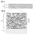
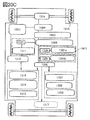
- FIG. 1A and 1B are views showing an example of a cross section of an electrode.
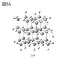
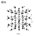
- 2A and 2B are examples of models with silicon.
- FIG. 3 is an example of a model having silicon and a model of a graphene compound.
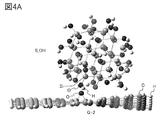
- 4A and 4B are examples of a model having silicon and a model of a graphene compound.
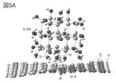
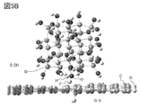
- 5A and 5B are examples of a model having silicon and a model of a graphene compound.
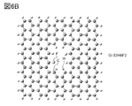
- 6A and 6B are examples of models of graphene compounds.
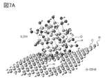
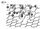
- 7A and 7B are examples of a model having silicon and a model of a graphene compound.
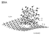
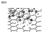
- 8A and 8B are examples of a model having silicon and a model of a graphene compound.
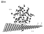
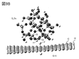
- FIG. 9A and 9B are examples of a model having silicon and a model of a graphene compound.
- FIG. 10 is a diagram showing an example of a method for manufacturing an electrode according to an aspect of the present invention.
- FIG. 11 is a diagram illustrating the crystal structure of the positive electrode active material.
- FIG. 12 is a diagram illustrating the crystal structure of the positive electrode active material.
- FIG. 13 is a diagram showing an example of a cross section of the secondary battery.
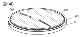
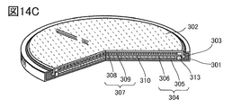
- 14A is an exploded perspective view of the coin-type secondary battery
- FIG. 14B is a perspective view of the coin-type secondary battery
- FIG. 14C is a sectional perspective view thereof.
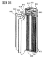
- 15A and 15B are examples of a cylindrical secondary battery
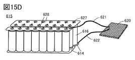
- FIG. 15C is an example of a plurality of cylindrical secondary batteries
- 15D is a storage battery having a plurality of cylindrical secondary batteries. This is an example of a system.
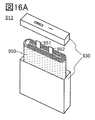
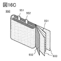
- 16A and 16B are diagrams for explaining an example of a secondary battery
- FIG. 16C is a diagram showing the inside of the secondary battery.
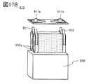
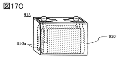
- 17A, 17B, and 17C are diagrams illustrating an example of a secondary battery.
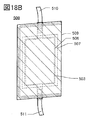
- 18A and 18B are views showing the appearance of the secondary battery.
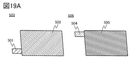
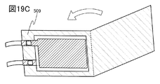
- 19A, 19B, and 19C are diagrams illustrating a method for manufacturing a secondary battery.
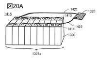
- 20A is a perspective view showing a battery pack
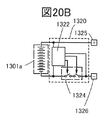
- FIG. 20B is a block diagram of the battery pack
- FIG. 20C is a block diagram of a vehicle having a motor.
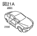
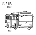
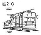
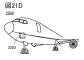
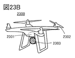
- 21A to 21D are diagrams illustrating an example of a moving body.
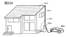
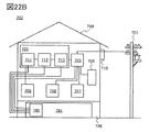
- 22A and 22B are diagrams illustrating a power storage device.
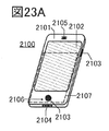
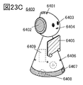
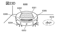
- 23A to 23D are diagrams illustrating an example of an electronic device.
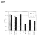
- FIG. 24 is the result of ToF-SIMS.
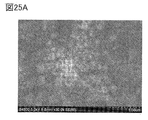
- 25A and 25B are surface SEM observation images.
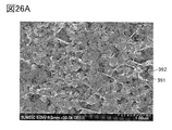
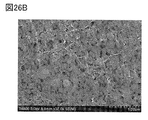
- 26A and 26B are cross-sectional SEM observation images.
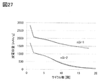
- FIG. 27 is the result of cycle characteristics.
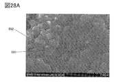
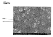
- 28A and 28B are surface SEM observation images.
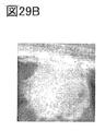
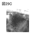
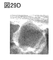
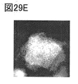
- 29A to 29E are EELS analysis results.
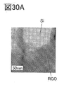
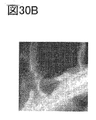
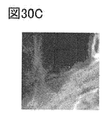
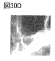
- 30A to 30E are EELS analysis results.
- Electrode 1 an electrode, an active material, a conductive agent, and the like according to one aspect of the present invention will be described.
- FIG. 1A is a schematic cross-sectional view showing an electrode according to an aspect of the present invention.
- the electrode 570 shown in FIG. 1A can be applied to the positive electrode and the negative electrode of the secondary battery.
- the electrode 570 includes at least the current collector 571 and the active material layer 572 formed in contact with the current collector 571.
- FIG. 1B is an enlarged view of a region surrounded by a broken line in FIG. 1A.
- the active material layer 572 has an electrolyte 581 and particles 582.
- the particles 582 preferably function as an active material.
- a material that functions as an active material can be used.
- the particles 582 preferably have, for example, a material that functions as an active material.
- the material having a sheet-like shape of the electrode 570 functions as a conductive agent, for example.
- the conductive agent can cling to the active material by hydrogen bonding, so that a highly conductive electrode can be realized.
- Various materials can be used as the particles 582. The materials that can be used as the particles 582 will be described later.
- the active material layer 572 preferably has a carbon-based material such as a graphene compound, carbon black, graphite, carbon fiber, and fullerene, and particularly preferably has a graphene compound.
- a carbon-based material such as a graphene compound, carbon black, graphite, carbon fiber, and fullerene
- acetylene black (AB) or the like can be used as the carbon black.
- graphite for example, natural graphite, artificial graphite such as mesocarbon microbeads, or the like can be used.
- These carbon-based materials have high conductivity and can function as a conductive agent in the active material layer.
- these carbon-based materials may function as an active material.
- FIG. 1B shows an example in which the active material layer 572 has the graphene compound 583.
- the graphene compound preferably clings to the particles 582 and one or more selected from carbon black, graphite, carbon fibers, and fullerenes.
- the graphene compound may cling to the particles 582 and the like via a binder.
- the graphene compound has a region in contact with the binder, and the binder has a region in contact with the particles 582.
- the graphene compound may have both a region in contact with the binder and a region in contact with the particles 482.
- the graphene compound may be arranged so as to cover the binder attached to the particles 582.
- carbon fiber such as mesophase pitch type carbon fiber and isotropic pitch type carbon fiber can be used.
- carbon fiber carbon nanofiber, carbon nanotube, or the like can be used.
- the carbon nanotubes can be produced, for example, by a vapor phase growth method.
- the active material layer may have one or more selected from metal powders such as copper, nickel, aluminum, silver, and gold, metal fibers, and conductive ceramic materials as the conductive agent.
- the content of the conductive auxiliary agent with respect to the total amount of the active material layer is preferably 1 wt% or more and 10 wt% or less, and more preferably 1 wt% or more and 5 Wt% or less.
- graphene compounds Unlike granular conductive materials such as carbon black that make point contact with active materials, graphene compounds enable surface contact with low contact resistance, so the amount of granular active materials and graphene compounds is smaller than that of ordinary conductive materials. It is possible to improve the electrical conductivity with. Therefore, the ratio of the active material in the active material layer can be increased. As a result, the discharge capacity of the secondary battery can be increased.
- the graphene compound according to one aspect of the present invention has excellent lithium permeability, the charge / discharge rate of the secondary battery can be increased.
- Particle-like carbon-containing compounds such as carbon black and graphite, and fibrous carbon-containing compounds such as carbon nanotubes easily enter minute spaces.
- the minute space refers to, for example, a region between a plurality of active materials.
- a carbon-containing compound that easily enters a minute space and a sheet-shaped carbon-containing compound such as graphene that can impart conductivity over multiple particles, the density of the electrodes can be increased and an excellent conductive path can be obtained. Can be formed.
- the secondary battery has the electrolyte of one aspect of the present invention, the operational stability of the secondary battery can be enhanced. That is, the secondary battery of one aspect of the present invention can have both high energy density and stability, and is effective as an in-vehicle secondary battery.
- the energy required to move it increases, and the cruising range also decreases.
- the cruising range can be extended with almost no change in the total weight of the vehicle equipped with the secondary battery of the same weight.
- the plurality of graphene compounds 583 are arranged in a three-dimensional network, and particles 582 are provided between the plurality of graphene compounds 583.
- the secondary battery of one aspect of the present invention can be miniaturized due to its high energy density, and can be quickly charged because of its high conductivity. Therefore, the configuration of the secondary battery according to one aspect of the present invention is also effective in a portable information terminal.
- the active material layer 572 preferably has a binder (not shown).
- the binder binds or fixes the electrolyte and the active material, for example. Further, the binder can bind or fix an electrolyte and a carbon-based material, an active material and a carbon-based material, a plurality of active materials, a plurality of carbon-based materials, and the like.
- binders polystyrene, methyl polyacrylate, methyl polymethacrylate (polymethylmethacrylate, PMMA), sodium polyacrylate, polyvinyl alcohol (PVA), polyethylene oxide (PEO), polypropylene oxide, polyimide, polyvinylidene chloride, polytetra It is preferable to use materials such as fluoroethylene, polyethylene, polypropylene, polyisobutylene, polyethylene terephthalate, nylon, polyvinylidene fluoride (PVDF), polyacrylonitrile (PAN), ethylenepropylene diene polymer, polyvinyl acetate, and nitrocellulose.
- PVDF polyvinylidene fluoride
- PAN polyacrylonitrile
- Polyimide has excellent stable properties thermally, mechanically and chemically.
- a dehydration reaction and a cyclization (imidization) reaction are carried out. These reactions can be carried out, for example, by heat treatment.
- graphene having a functional group containing oxygen is used as the graphene compound and polyimide is used as the binder in the electrode of one aspect of the present invention
- the graphene compound can be reduced by the heat treatment, and the process can be simplified. It will be possible.
- heat treatment can be performed at a heating temperature of, for example, 200 ° C. or higher. By performing the heat treatment at a heating temperature of 200 ° C. or higher, the reduction reaction of the graphene compound can be sufficiently performed, and the conductivity of the electrode can be further enhanced.
- Fluoropolymer which is a polymer material having fluorine, specifically polyvinylidene fluoride (PVDF) or the like can be used.
- PVDF is a resin having a melting point in the range of 134 ° C. or higher and 169 ° C. or lower, and is a material having excellent thermal stability.
- a rubber material such as styrene-butadiene rubber (SBR), styrene-isoprene-styrene rubber, acrylonitrile-butadiene rubber, butadiene rubber, or ethylene-propylene-diene copolymer as the binder.
- SBR styrene-butadiene rubber
- fluororubber can be used as the binder.
- a water-soluble polymer for example, a polysaccharide or the like can be used.
- a polysaccharide one or more selected from cellulose derivatives such as carboxymethyl cellulose (CMC), methyl cellulose, ethyl cellulose, hydroxypropyl cellulose, diacetyl cellulose, and regenerated cellulose, and starch and the like can be used. Further, it is more preferable to use these water-soluble polymers in combination with the above-mentioned rubber material.
- the binder may be used in combination of a plurality of the above.
- the graphene compound 583 is flexible and has flexibility, and can cling to the particles 582 like natto. Further, for example, the particles 582 can be compared to soybean, and the graphene compound 583 can be compared to a sticky component, for example, polyglutamic acid.
- a sticky component for example, polyglutamic acid.
- a plurality of graphene compounds 583 form a three-dimensional network structure, a structure in which polygons are arranged, for example, a honeycomb structure in which hexagons are arranged in a matrix, and an electrolyte, a plurality of active substances, and a plurality of carbon systems are formed in the network.
- the graphene compound 583 can form a three-dimensional conductive path and suppress the dropout of the electrolyte from the current collector.
- polygons having different numbers of sides may be mixed and arranged. Therefore, the graphene compound 583 may function as a conductive agent and a binder in the active material layer 572.
- the particles 582 can have various shapes such as a rounded shape and a shape having corners. Further, in the cross section of the electrode, the particles 582 can have various cross-sectional shapes such as a circle, an ellipse, a figure having a curve, a polygon, and the like. For example, FIG. 1B shows an example in which the cross section of the particle 582 has a rounded shape, but the cross section of the particle 582 may have an angle. Further, a part may be rounded and a part may have corners.
- the graphene compound is graphene, multi-layer graphene, multi-graphene, graphene oxide, multi-layer graphene oxide, multi-graphene oxide, reduced graphene oxide, reduced multi-layer graphene oxide, reduced multi-graphene oxide, graphene.
- the graphene compound has carbon, has a flat plate shape, a sheet shape, or the like, and has a two-dimensional structure formed by a carbon 6-membered ring.
- the two-dimensional structure formed by the carbon 6-membered ring may be called a carbon sheet.
- the graphene compound may have a functional group. Further, the graphene compound preferably has a bent shape.
- the graphene compound may also be curled up into carbon nanofibers.
- graphene oxide means, for example, one having carbon and oxygen, having a sheet-like shape, and having a functional group, particularly an epoxy group, a carboxy group or a hydroxy group.
- the reduced graphene oxide in the present specification and the like means, for example, a graphene oxide having carbon and oxygen, having a sheet-like shape, and having a two-dimensional structure formed by a carbon 6-membered ring. It may be called a carbon sheet. Although one reduced graphene oxide functions, a plurality of reduced graphene oxides may be laminated.
- the reduced graphene oxide preferably has a portion having a carbon concentration of more than 80 atomic% and an oxygen concentration of 2 atomic% or more and 15 atomic% or less. By setting such carbon concentration and oxygen concentration, it is possible to function as a highly conductive conductive material even in a small amount.
- the reduced graphene oxide has an intensity ratio G / D of G band to D band of 1 or more in the Raman spectrum.
- the reduced graphene oxide having such an intensity ratio can function as a highly conductive conductive material even in a small amount.
- the sheet-like graphene compound is dispersed substantially uniformly in the internal region of the active material layer. Since the plurality of graphene compounds are formed so as to partially cover the plurality of granular active substances or to stick to the surface of the plurality of granular active substances, they are in surface contact with each other.
- graphene compound net By binding a plurality of graphene compounds to each other, a mesh-like graphene compound sheet (hereinafter referred to as graphene compound net or graphene net) can be formed.
- the graphene net When the active material is covered with graphene net, the graphene net can also function as a binder for binding the active materials to each other. Therefore, since the amount of the binder can be reduced or not used, the ratio of the active material to the electrode volume and the electrode weight can be improved. That is, the charge / discharge capacity of the secondary battery can be increased.
- graphene oxide as a graphene compound, mix it with an active material to form a layer to be an active material layer, and then reduce the amount. That is, it is preferable that the active material layer after completion has reduced graphene oxide.
- the graphene compound can be dispersed substantially uniformly in the internal region of the active material layer.
- the graphene compounds remaining in the active material layer partially overlap and are dispersed to the extent that they are in surface contact with each other. Can form a three-dimensional conductive path.
- the graphene oxide may be reduced, for example, by heat treatment or by using a reducing agent.
- a graphene compound which is a conductive material, is formed as a film by covering the entire surface of the active material, and the active materials are electrically connected to each other with the graphene compound to form a conductive path. It can also be formed.
- the graphene compound may be mixed with the material used for forming the graphene compound and used for the active material layer.
- particles used as a catalyst for forming a graphene compound may be mixed with the graphene compound.
- the catalyst for forming the graphene compound include particles having silicon oxide (SiO 2 , SiO x (x ⁇ 2)), aluminum oxide, iron, nickel, ruthenium, iridium, platinum, copper, germanium and the like. ..
- the particles preferably have a D50 of 1 ⁇ m or less, and more preferably 100 nm or less.
- the graphene compound according to one aspect of the present invention preferably has holes in a part of the carbon sheet.
- the graphene compound of one aspect of the present invention by providing a hole through which carrier ions such as lithium ions can pass in a part of the carbon sheet, carrier ions can be inserted and removed on the surface of the active material covered with the graphene compound. It becomes easier to do so, and the rate characteristics of the secondary battery can be improved.
- the holes provided in a part of the carbon sheet may be referred to as vacancies, defects or voids.
- the graphene compound according to one aspect of the present invention preferably has pores provided by a plurality of carbon atoms and one or more fluorine atoms. Further, it is preferable that the plurality of carbon atoms are bonded in a ring shape, and it is preferable that one or more of the plurality of carbon atoms bonded in a ring shape is terminated by the fluorine. Fluorine has a high electronegativity and tends to be negatively charged. The approach of positively charged lithium ions causes an interaction, which stabilizes the energy and reduces the barrier energy through which the lithium ions pass through the pores. Therefore, since the pores of the graphene compound have fluorine, it is possible to realize a graphene compound in which lithium ions easily pass through even in small pores and have excellent conductivity.
- Negative electrode active materials include materials that can react with carrier ions of secondary batteries, materials that can insert and remove carrier ions, materials that can alloy with metals that become carrier ions, and carrier ions. It is preferable to use a material capable of dissolving and precipitating the metal.
- the following is an example of a negative electrode active material.
- Silicon can be used as the negative electrode active material.
- the electrode 570 it is preferable to use particles having silicon as the particles 582.
- a metal or compound having one or more elements selected from tin, gallium, aluminum, germanium, lead, antimony, bismuth, silver, zinc, cadmium and indium can be used.
- an alloy-based compound using such elements for example, Mg 2 Si, Mg 2 Ge , Mg 2 Sn, SnS 2, V 2 Sn 3, FeSn 2, CoSn 2, Ni 3 Sn 2, Cu 6 Sn 5 , Ag 3 Sn, Ag 3 Sb, Ni 2 MnSb, CeSb 3 , LaSn 3 , La 3 Co 2 Sn 7 , CoSb 3 , InSb, SbSn and the like.
- a material having a low resistance may be used by adding phosphorus, arsenic, boron, aluminum, gallium or the like as impurity elements to silicon.
- a silicon material predoped with lithium may be used.
- a predoping method there are methods such as mixing and annealing lithium fluoride, lithium carbonate and the like with silicon, and a mechanical alloy of lithium metal and silicon.
- lithium is doped by a charge / discharge reaction in combination with an electrode such as lithium metal, and then an electrode that becomes a counter electrode using the doped electrode (for example, a positive electrode with respect to a pre-doped negative electrode). May be combined to produce a secondary battery.
- silicon nanoparticles can be used as the particles 582.
- the average diameter of the silicon nanoparticles is, for example, preferably 5 nm or more and less than 1 ⁇ m, more preferably 10 nm or more and 300 nm or less, and further preferably 10 nm or more and 100 nm or less.
- Silicon nanoparticles may have crystallinity. Further, the silicon nanoparticles may have a crystalline region and an amorphous region.
- the material having silicon for example, a material represented by SiO x (x is preferably smaller than 2, more preferably 0.5 or more and 1.6 or less) can be used.
- a form having a plurality of crystal grains in one particle can be used.
- a form having one or a plurality of silicon crystal grains in one particle can be used.
- the one particle may have silicon oxide around the crystal grain of silicon.
- the silicon oxide may be amorphous. It may be a particle in which a graphene compound is clinging to a secondary particle of silicon.
- Li 2 SiO 3 and Li 4 SiO 4 can be used as the compound having silicon.
- Li 2 SiO 3 and Li 4 SiO 4 may be crystalline or amorphous, respectively.
- NMR nuclear magnetic resonance
- XRD X-ray diffraction
- Raman spectroscopy Raman spectroscopy
- SEM scanning electron microscopy
- TEM transmission electron microscopy
- EDX energy dispersion X-ray spectroscopy
- the negative electrode active material for example, carbon-based materials such as graphite, graphitizable carbon, non-graphitizable carbon, carbon nanotubes, carbon black and graphene compounds can be used.
- the negative electrode active material for example, an oxide having one or more elements selected from titanium, niobium, tungsten and molybdenum can be used.
- the negative electrode active material a plurality of metals, materials, compounds, etc. shown above can be used in combination.
- Examples of the negative electrode active material include SnO, SnO 2 , titanium dioxide (TIO 2 ), lithium titanium oxide (Li 4 Ti 5 O 12 ), lithium-graphite interlayer compound (Li x C 6 ), and niobium pentoxide (Nb 2 O). 5 ) Oxides such as tungsten oxide (WO 2 ) and molybdenum oxide (MoO 2 ) can be used.
- Li 2.6 Co 0.4 N 3 shows a large charge / discharge capacity (900 mAh / g) and is preferable.
- double nitride of lithium and a transition metal as a negative electrode material, preferably can be combined with the material of V 2 O 5, Cr 3 O 8 or the like which does not contain lithium ions as a positive electrode material. Even when a material containing lithium ions is used as the positive electrode material, a double nitride of lithium and a transition metal can be used as the negative electrode material by desorbing the lithium ions contained in the positive electrode material in advance.
- a material that causes a conversion reaction can also be used as a negative electrode active material.
- a transition metal oxide that does not undergo an alloying reaction with lithium such as cobalt oxide (CoO), nickel oxide (NiO), and iron oxide (FeO)
- Materials that cause a conversion reaction include oxides such as Fe 2 O 3 , CuO, Cu 2 O, RuO 2 , Cr 2 O 3 , sulfides such as CoS 0.89 , NiS, and CuS, and Zn 3 N 2. , Cu 3 N, Ge 3 N 4 or the like nitride, NiP 2, FeP 2, CoP 3 etc. phosphide, also at the FeF 3, BiF 3 fluoride and the like. Since the potential of the fluoride is high, it may be used as a positive electrode material.
- the particles 582 may change in volume due to charge / discharge, but by arranging an electrolyte having fluorine between a plurality of particles 582 in the electrode, the particles are slippery even if the volume changes during charge / discharge. Since cracks are suppressed, there is an effect that the cycle characteristics are dramatically improved. It is important that an organic compound having fluorine is present between the plurality of active substances constituting the electrode.
- model S_H hydrogen-terminated silicon
- model S_OH hydroxy group-terminated silicon
- graphene As graphene (model G-1), a structure consisting of 170 carbon atoms and 36 hydrogen atoms was used. All 36 hydrogen atoms terminate the ends of graphene.
- Graphene compounds include graphene having one carbon bonded to an epoxy group (model G-2), graphene having two carbons bonded to a hydroxyl group (model G-3), and graphene having two hydrogen-terminated carbons (model G-3).
- model G-2 graphene having one carbon bonded to an epoxy group
- model G-3 graphene having two carbons bonded to a hydroxyl group
- model G-3 graphene having two hydrogen-terminated carbons
- Five models were used: model G-4) and graphene with two fluorine-terminated carbons (model G-5).
- the functional group, or atom-terminated carbon is located near the center of the graphene plane.
- FIG. 3 shows an example of the interaction between the particles having silicon and the graphene compound after the optimization.
- the optimization shows how the silicon-bearing particles approach the graphene compound in distance.
- the graphene compound was observed to be curved.
- the curvature of the graphene compound is considered to be due to the London dispersion force.
- FIG. 3 shows the state when the hydroxy group-terminated silicon (model S_OH) and graphene (model G-1) approach each other.
- the stabilization energy was calculated for each combination.
- the results are shown in Table 2.
- the energy when the particles having silicon and the graphene compound were arranged at infinity was used as a reference, and the absolute value of the difference from the reference was used as the stabilizing energy.
- the stabilization energy of the hydroxy group-terminated silicon was higher than that of the hydrogen-terminated silicon (model S_H).
- graphene compounds models G-2 to G-5) having carbon bonded to a functional group, a hydrogen atom, or a fluorine atom in terms of graphene have a higher stabilizing energy than graphene (model G-1). it was high.
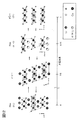
- FIG. 4A shows a state in which silicon terminated with a hydroxy group (model S_OH) and graphene having carbon bonded to an epoxy group (model G-2) are brought close to each other. It was suggested that a hydrogen bond was formed between the oxygen contained in the epoxy group and the hydroxy group on the silicon surface.
- FIG. 4B shows a state in which silicon terminated with a hydroxy group (model S_OH) and graphene having a carbon bonded to the hydroxy group (model G-3) are brought close to each other. It was suggested that a hydrogen bond was formed between both hydroxy groups.
- FIG. 5A shows a state in which silicon terminated with a hydroxy group (model S_OH) and graphene having carbon terminated by a hydrogen atom (model G-4) are brought close to each other. It was suggested that a hydrogen bond was formed between the hydrogen atom of graphene and the hydroxy group on the silicon surface.
- FIG. 5B shows a state in which silicon terminated with a hydroxy group (model S_OH) and graphene having carbon terminated by a fluorine atom (model G-5) are brought close to each other. It was suggested that a hydrogen bond was formed between the fluorine atom of graphene and the hydroxy group on the silicon surface.
- the stabilization energy is increased by forming a hydrogen bond with the graphene compound by terminating the silicon surface with a hydroxy group.
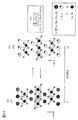
- FIGS. 6A and 6B show an example of the composition of a graphene compound having pores.
- model G-22H8 The configuration shown in FIG. 6A (hereinafter referred to as model G-22H8) has a 22-membered ring, and 8 carbons out of the carbons constituting the 22-membered ring are each terminated by hydrogen.
- the model G-22H8 has a structure in graphene in which two linked 6-membered rings are removed and the carbon bonded to the removed 6-membered ring is terminated with hydrogen.
- model G-22H6F2 The configuration shown in FIG. 6B (hereinafter referred to as model G-22H6F2) has a 22-membered ring, and 6 of the 8 carbons constituting the 22-membered ring are terminated by hydrogen and 2 carbons are terminated. Carbon is terminated by fluorine.
- the model G-22H6F2 has a structure in graphene in which two linked 6-membered rings are removed and the carbon bonded to the removed 6-membered ring is terminated with hydrogen or fluorine.
- the stabilization energy was calculated for the combination of the particles having silicon and the graphene compound having pores. The results are shown in Table 3.
- FIG. 7A shows the state when the silicon (model S_OH) terminated with a hydroxy group and the model G-22H8 are brought close to each other.
- FIG. 7B is an enlarged view including a region in which the silicon (model S_OH) terminated with a hydroxy group and the model G-22H8 approach each other. As shown by the broken line in FIG. 7B, it was suggested that a hydrogen bond was formed between the hydrogen atom of graphene and the hydroxy group on the silicon surface.
- FIG. 8A shows the state when the hydroxy group-terminated silicon (model S_OH) and the model G-22H6F2 are brought close to each other.
- FIG. 8B is an enlarged view including a region in which the hydroxy group-terminated silicon (model S_OH) and the model G-22H6F2 approach each other. As shown by the broken line in FIG. 8B, it was suggested that a hydrogen bond was formed between the hydrogen atom of graphene and the oxygen of the hydroxy group on the silicon surface. It was also suggested that a hydrogen bond is formed between the fluorine atom of graphene and the hydrogen of the hydroxy group on the silicon surface.
- the graphene compound has fluorine in addition to hydrogen, in addition to the hydrogen bond between the oxygen atom of the hydroxy group and the hydrogen atom of the graphene compound, the hydrogen bond between the hydrogen atom of the hydroxy group and the fluorine atom of the graphene compound. was also formed, suggesting that the interaction between hydrogen-bearing particles and the graphene compound is stronger and the stabilizing energy is even higher.
- the hydrogen-terminated silicon (model S_H) has a stabilization energy with the graphene compound having two types of pores shown in Table 2 as compared with the hydroxy group-terminated silicon (model S_OH). It was small.
- the silicon surface is terminated by a hydroxy group and the graphene compound has pores terminated by hydrogen or fluorine, so that a hydrogen bond is formed and the stabilization energy is increased.
- model S_Ox a model of silicon oxide
- a structure consisting of 20 silicon atoms, 28 hydrogen atoms and 54 oxygen atoms was used.
- the terminal dangling bond was terminated with a hydroxy group.
- FIG. 9A shows an optimized state of silicon oxide and graphene having carbon terminated by a hydroxy group (model G-3), and FIG. 9B shows silicon oxide and carbon terminated by fluorine.
- the graphene having (model G-5) and the optimized state are shown respectively. It was suggested that even in silicon oxide terminated by a hydroxy group, the graphene compound has a functional group or pores, so that the bond becomes stronger.
- FIG. 10 is a flow chart showing an example of a method for manufacturing an electrode according to an aspect of the present invention.
- step S71 particles having silicon are prepared.
- the particles having silicon for example, the particles described as the above particles 582 can be used.
- step S72 prepare a solvent.
- the solvent for example, one or a mixture of water, methanol, ethanol, acetone, tetrahydrofuran (THF), dimethylformamide (DMF), N-methylpyrrolidone (NMP) and dimethyl sulfoxide (DMSO) may be used. Can be done.
- step S73 the particles having silicon prepared in step S71 and the solvent prepared in step S72 are mixed, the mixture is recovered in step S74, and the mixture E-1 is obtained in step S75.
- a kneader or the like can be used for mixing.
- the kneading machine for example, a rotation / revolution mixer or the like can be used.
- step S80 the graphene compound is prepared.
- step S81 the mixture E-1 and the graphene compound prepared in step S80 are mixed, and in step S82, the mixture is recovered.
- the recovered mixture is preferably in a high viscosity state. Due to the high viscosity of the mixture, solid kneading (kneading at high viscosity) can be performed in the next step S83.
- kneading is performed in step S83.
- the kneading can be performed using, for example, a spatula. By kneading, it is possible to form a mixture in which the particles having silicon and the graphene compound are well mixed and the graphene compound has excellent dispersibility.
- step S84 the kneaded mixture is mixed.
- a kneader or the like can be used for mixing.
- the mixed mixture is recovered in step S85.
- n is, for example, a natural number of 2 or more and 10 or less.
- a solvent when the mixture is in a dry state, it is preferable to add a solvent. Further, for example, there may be a case where the solvent is added or a case where the solvent is not added in step S83 in n repetitions. On the other hand, if too much solvent is added, the viscosity decreases and the effect of kneading decreases.
- step S86 After repeating steps S83 to S85 n times, the mixture E-2 is obtained (step S86).
- step S87 prepare a binder.
- the materials described above can be used, and it is particularly preferable to use polyimide.
- a precursor of a material used as a binder may be prepared.
- a polyimide precursor is prepared.
- step S88 the mixture E-2 and the binder prepared in step S87 are mixed.
- step S89 the viscosity is adjusted. Specifically, for example, a solvent of the same type as the solvent prepared in step S72 is prepared and added to the mixture obtained in step S88. By adjusting the viscosity, for example, the thickness, density, etc. of the electrode obtained in step S97 may be adjusted.
- step S92 the mixture whose viscosity was adjusted in step S89 is mixed in step S90 and recovered in step S91 to obtain a mixture E-3 (step S92).
- the mixture E-3 obtained in step S92 is called, for example, a slurry.
- step S94 the mixture E-3 is applied onto the current collector prepared in step S93.
- a slot die method, a gravure method, a blade method, a method combining them, or the like can be used.
- a continuous coating machine or the like may be used for coating.
- step S95 the first heating is performed.
- the first heating causes the solvent to volatilize.
- the first heating may be performed in a temperature range of 50 ° C. or higher and 200 ° C. or lower, preferably 60 ° C. or higher and 150 ° C. or lower.
- heat treatment is performed on a hot plate in an atmospheric atmosphere under the conditions of 30 ° C. or higher and 70 ° C. or lower for 10 minutes or longer, and then, for example, under a reduced pressure environment under the conditions of room temperature or higher and 100 ° C. or lower for 1 hour or longer and 10 hours or lower.
- the heat treatment may be performed.
- the heat treatment may be performed using a drying oven or the like.
- heat treatment may be performed at a temperature of 30 ° C. or higher and 120 ° C. or lower for 30 seconds or longer and 2 hours or shorter.
- the temperature may be raised step by step.
- the heat treatment may be further performed at a temperature of 65 ° C. or higher for 1 minute or longer.
- step S96 the second heating is performed.
- the cycloaddition reaction of the polyimide occurs by the second heating.
- the second heating may cause a dehydration reaction of the polyimide.
- the first heating may cause a dehydration reaction of the polyimide.
- the cyclization reaction of the polyimide may occur in the first heating.
- the reduction reaction of the graphene compound occurs in the second heating.
- step S97 an electrode having an active material layer provided on the current collector is obtained.
- the thickness of the active material layer thus formed may be, for example, preferably 5 ⁇ m or more and 300 ⁇ m or less, and more preferably 10 ⁇ m or more and 150 ⁇ m or less.
- the amount of the active material supported by the active material layer may be, for example, preferably 2 mg / cm 2 or more and 50 mg / cm 2 or less.
- the active material layer may be formed on both sides of the current collector, or may be formed on only one side. Alternatively, it may have a region in which active material layers are partially formed on both sides.
- pressing may be performed by a compression method such as a roll press method or a flat plate press method. Heat may be applied when pressing.
- the positive electrode active material examples include a layered rock salt type crystal structure or a composite oxide having a spinel type crystal structure.
- a positive electrode active material for example, a compound having an olivine type crystal structure can be mentioned.
- the positive electrode active material include compounds such as LiFePO 4 , LiFeO 2 , LiNiO 2 , LiMn 2 O 4 , V 2 O 5 , Cr 2 O 5 , and MnO 2 .
- a lithium manganese composite oxide that can be represented by the composition formula Li a Mn b M c Od can be used.
- the element M a metal element selected from other than lithium and manganese, silicon, and phosphorus are preferably used, and nickel is more preferable.
- the lithium manganese composite oxide refers to an oxide containing at least lithium and manganese, and includes chromium, cobalt, aluminum, nickel, iron, magnesium, molybdenum, zinc, indium, gallium, copper, titanium, niobium, and silicon. And at least one element selected from the group consisting of phosphorus and the like may be contained.
- a material having a layered rock salt type crystal structure such as lithium cobalt oxide (LiCoO 2 ) has a high discharge capacity and is excellent as a positive electrode active material for a secondary battery.
- the material having a layered rock salt type crystal structure include a composite oxide represented by LiMO 2.
- the metal M contains the metal Me1.
- the metal Me1 is one or more metals containing cobalt.
- the metal M can further contain the metal X in addition to the metal Me1.
- Metal X is one or more metals selected from magnesium, calcium, zirconium, lanthanum, barium, copper, potassium, sodium and zinc.
- the positive electrode active material will be described with reference to FIGS. 11 and 12.
- the positive electrode active material produced according to one aspect of the present invention can reduce the displacement of the CoO 2 layer in repeated deep charging and discharging. Furthermore, the change in volume can be reduced. Therefore, the compound can realize excellent cycle characteristics. In addition, the compound can have a stable crystal structure in a state of deep charging depth. Therefore, the compound may not easily cause a short circuit when the state of deep charge depth is maintained. In such a case, safety is further improved, which is preferable.
- the difference in volume between a sufficiently discharged state and a state with a high charging depth is small when compared with the change in crystal structure and the same number of transition metal atoms.
- the positive electrode active material is preferably represented by a layered rock salt type structure, and the region is represented by a space R-3m.
- the positive electrode active material is a region having lithium, metal Me1, oxygen and metal X.
- FIG. 11 shows an example of the crystal structure before and after charging and discharging the positive electrode active material.
- the surface layer portion of the positive electrode active material has titanium, magnesium and oxygen in addition to or in place of the region represented by the layered rock salt type structure described in FIG. 11 and the like below, and is different from the layered rock salt type structure. It may have a crystal represented by a structure. For example, it may have titanium, magnesium and oxygen, and may have crystals represented by a spinel structure.
- the crystal structure of FIG. 11 at a charge depth of 0 (discharged state) is R-3 m (O3), which is the same as that of FIG.
- the positive electrode active material shown in FIG. 11 has a crystal having a structure different from that of the H1-3 type crystal structure when the charge depth is sufficiently charged.
- this structure is a space group R-3m and is not a spinel-type crystal structure, ions such as cobalt and magnesium occupy the oxygen 6-coordination position, and the arrangement of cations has symmetry similar to that of the spinel-type. Further, the symmetry of the CoO 2 layer of the structure is the same as type O3.
- this structure is referred to as an O3'type crystal structure or a pseudo-spinel type crystal structure in the present specification and the like.
- lithium may be present at any lithium site with a probability of about 20%, but the present invention is not limited to this. It may be present only in some specific lithium sites.
- magnesium is dilutely present between the CoO 2 layers, that is, in the lithium site.
- halogens such as fluorine may be randomly and dilutely present at the oxygen sites.
- light elements such as lithium may occupy the oxygen 4-coordination position, and in this case as well, the ion arrangement has symmetry similar to that of the spinel type.
- the O3'type crystal structure has Li randomly between layers but is similar to the CdCl 2 type crystal structure.
- This crystal structure similar to CdCl type 2 is similar to the crystal structure when lithium nickel oxide is charged to a charging depth of 0.94 (Li 0.06 NiO 2 ), but contains a large amount of pure lithium cobalt oxide or cobalt. It is known that layered rock salt type positive electrode active materials do not usually have this crystal structure.
- Layered rock salt crystals and anions of rock salt crystals have a cubic close-packed structure (face-centered cubic lattice structure). It is presumed that the O3'type crystal also has a cubic close-packed structure for anions. When they come into contact, there is a crystal plane in which the cubic close-packed structure composed of anions is oriented in the same direction.
- the space group of layered rock salt type crystals and O3'type crystals is R-3m
- the space group of rock salt type crystals Fm-3m (space group of general rock salt type crystals) and Fd-3m (simplest symmetry).
- the mirror index of the crystal plane satisfying the above conditions is different between the layered rock salt type crystals and the O3'type crystals and the rock salt type crystals.
- the orientations of the crystals are substantially the same when the orientations of the cubic close-packed structures composed of anions are aligned. be.
- the positive electrode active material shown in FIG. 11 has high structural stability even when the charging voltage is high.
- a charging voltage having an H1-3 type crystal structure for example, a voltage of about 4.6 V based on the potential of a lithium metal, results in an H1-3 type crystal structure.
- the positive electrode active material can retain the crystal structure of R-3m (O3) even at the charging voltage of about 4.6V.
- There is a region where an O3'type crystal structure can be obtained even at a higher charging voltage for example, a voltage of about 4.65 V to 4.7 V with reference to the potential of lithium metal.
- H1-3 type crystals may finally be observed in the positive electrode active material of one aspect of the present invention.
- the positive electrode active material of one embodiment of the present invention can have an O3'type crystal structure.
- the voltage of the secondary battery is lower than the above by the potential of graphite.
- the potential of graphite is about 0.05V to 0.2V based on the potential of lithium metal. Therefore, for example, even when the voltage of the secondary battery using graphite as the negative electrode active material is 4.3 V or more and 4.5 V or less, the positive electrode active material of one aspect of the present invention can retain the crystal structure of R-3m (O3), and further.
- the charging voltage is increased, for example, a region where the O3'type crystal structure can be obtained even when the voltage of the secondary battery exceeds 4.5 V and is 4.6 V or less. Further, when the charging voltage is lower, for example, even if the voltage of the secondary battery is 4.2 V or more and less than 4.3 V, the positive electrode active material of one aspect of the present invention may have an O3'type crystal structure.
- the crystal structure does not easily collapse even if charging and discharging are repeated at a high voltage.
- the difference in volume per unit cell between the O3 type crystal structure having a charging depth of 0 and the O3'type crystal structure having a charging depth of 0.8 is 2.5% or less, which is more detailed. Is less than 2.2%.
- the coordinates of cobalt and oxygen in the unit cell are within the range of Co (0,0,0.5), O (0,0,x), 0.20 ⁇ x ⁇ 0.25. Can be indicated by.
- Magnesium which is randomly and dilutely present between the two CoO layers, that is, at the lithium site, has an effect of suppressing the displacement of the two CoO layers when charged at a high voltage. Therefore , if magnesium is present between the CoO 2 layers, it tends to have an O3'type crystal structure.
- a halogen compound such as a fluorine compound
- a fluorine compound causes the melting point of lithium cobalt oxide to drop. By lowering the melting point, it becomes easy to distribute magnesium throughout the particles at a temperature at which cationic mixing is unlikely to occur. Further, if a fluorine compound is present, it can be expected that the corrosion resistance to hydrofluoric acid generated by the decomposition of the electrolyte is improved.
- the magnesium concentration is higher than the desired value, the effect on stabilizing the crystal structure may be reduced. It is thought that magnesium enters cobalt sites in addition to lithium sites.
- the number of atoms of magnesium contained in the positive electrode active material produced by one aspect of the present invention is preferably 0.001 times or more and 0.1 times or less, and more than 0.01 times and less than 0.04 times the number of atoms of cobalt. More preferably, about 0.02 times is further preferable.
- the concentration of magnesium shown here may be, for example, a value obtained by elemental analysis of the entire particles of the positive electrode active material using ICP-MS or the like, or a value of the blending of raw materials in the process of producing the positive electrode active material. It may be based.
- the number of nickel atoms contained in the positive electrode active material is preferably 7.5% or less, preferably 0.05% or more and 4% or less, and more preferably 0.1% or more and 2% or less of the atomic number of cobalt.
- the concentration of nickel shown here may be, for example, a value obtained by elemental analysis of the entire particles of the positive electrode active material using ICP-MS or the like, or a value of the blending of raw materials in the process of producing the positive electrode active material. May be based.
- the average particle diameter (D50: also referred to as median diameter) is preferably 1 ⁇ m or more and 100 ⁇ m or less, more preferably 2 ⁇ m or more and 40 ⁇ m or less, and further preferably 5 ⁇ m or more and 30 ⁇ m or less.
- a positive electrode active material exhibits an O3'type crystal structure when charged at a high voltage is determined by XRD, electron diffraction, neutron diffraction, electron spin resonance (ESR), and electron spin resonance (ESR). It can be determined by analysis using nuclear magnetic resonance (NMR) or the like.
- XRD can analyze the symmetry of transition metals such as cobalt contained in the positive electrode active material with high resolution, compare the height of crystallinity and the orientation of crystals, and analyze the periodic strain and crystallite size of the lattice. It is preferable in that sufficient accuracy can be obtained even if the positive electrode obtained by disassembling the secondary battery is measured as it is.
- the positive electrode active material is characterized in that the crystal structure does not change much between the state of being charged with a high voltage and the state of being discharged.
- a material in which a crystal structure having a large change from the discharged state occupies 50 wt% or more in a state of being charged at a high voltage is not preferable because it cannot withstand the charging / discharging of a high voltage.
- the desired crystal structure may not be obtained simply by adding an impurity element. For example, even if lithium cobaltate having magnesium and fluorine is common, the O3'type crystal structure becomes 60 wt% or more when charged at a high voltage, and the H1-3 type crystal structure becomes 50 wt% or more. There are cases where it occupies.
- the O3'type crystal structure becomes approximately 100 wt%, and when the predetermined voltage is further increased, an H1-3 type crystal structure may occur. Therefore, it is preferable that the crystal structure of the positive electrode active material is analyzed by XRD or the like. By using it in combination with measurement such as XRD, more detailed analysis can be performed.
- the positive electrode active material charged or discharged at a high voltage may change its crystal structure when exposed to the atmosphere.
- the O3'type crystal structure may change to the H1-3 type crystal structure. Therefore, it is preferable to handle all the samples in an inert atmosphere such as an atmosphere containing argon.
- the positive electrode active material shown in FIG. 12 is lithium cobalt oxide (LiCoO 2 ) to which the metal X is not added.
- the crystal structure of lithium cobalt oxide shown in FIG. 12 changes depending on the charging depth.
- the lithium cobaltate is charged depth 0 (discharged state) has a region having a crystal structure of the space group R-3m, CoO 2 layers is present three layers in the unit cell. Therefore, this crystal structure may be referred to as an O3 type crystal structure.
- the CoO 2 layer is a structure in which an octahedral structure in which oxygen is coordinated to cobalt is continuous with a plane in a shared ridge state.
- this crystal structure may be referred to as an O1 type crystal structure.
- lithium cobalt oxide when the charging depth is about 0.8 has a crystal structure of the space group R-3m.
- This structure can be said to be a structure in which CoO 2 structures such as P-3m1 (O1) and LiCoO 2 structures such as R-3m (O3) are alternately laminated. Therefore, this crystal structure may be referred to as an H1-3 type crystal structure.
- the H1-3 type crystal structure has twice the number of cobalt atoms per unit cell as the other structures.
- the c-axis of the H1-3 type crystal structure is shown as a half of the unit cell.
- the coordinates of cobalt and oxygen in the unit cell are set to Co (0, 0, 0.42150 ⁇ 0.00016), O 1 (0, 0, 0.267671 ⁇ 0.00045). , O 2 (0, 0, 0.11535 ⁇ 0.00045).
- O 1 and O 2 are oxygen atoms, respectively.
- the H1-3 type crystal structure is represented by a unit cell using one cobalt and two oxygens.
- the O3'type crystal structure of one aspect of the present invention is preferably represented by a unit cell using one cobalt and one oxygen.
- the difference in volume is also large.
- the difference in volume between the H1-3 type crystal structure and the discharged state O3 type crystal structure is 3.0% or more.
- the continuous structure of two CoO layers such as P-3m1 (O1) of the H1-3 type crystal structure is likely to be unstable.
- the crystal structure of lithium cobalt oxide collapses when high voltage charging and discharging are repeated.
- the collapse of the crystal structure causes deterioration of the cycle characteristics. It is considered that this is because the crystal structure collapses, the number of sites where lithium can stably exist decreases, and it becomes difficult to insert and remove lithium.
- ⁇ Electrolyte> When a liquid electrolyte is used for the secondary battery, for example, as the electrolyte, ethylene carbonate (EC), propylene carbonate (PC), butylene carbonate, chloroethylene carbonate, vinylene carbonate, ⁇ -butyrolactone, ⁇ -valerolactone, dimethyl carbonate (DMC). ), Diethyl carbonate (DEC), ethyl methyl carbonate (EMC), methyl formate, methyl acetate, ethyl acetate, methyl propionate, ethyl propionate, propyl propionate, methyl butyrate, 1,3-dioxane, 1,4-dioxane.
- EC ethylene carbonate
- PC propylene carbonate
- C butylene carbonate
- chloroethylene carbonate vinylene carbonate
- vinylene carbonate ⁇ -butyrolactone
- ⁇ -valerolactone dimethyl carbonate (DMC).
- DME Dimethoxyethane
- Ionic liquids normally temperature molten salt
- Ionic liquids consist of cations and anions, including organic cations and anions.
- organic cation examples include aliphatic onium cations such as quaternary ammonium cations, tertiary sulfonium cations, and quaternary phosphonium cations, and aromatic cations such as imidazolium cations and pyridinium cations.
- a monovalent amide anion a monovalent methide anion, a fluorosulfonic acid anion, a perfluoroalkyl sulfonic acid anion, a tetrafluoroborate anion, a perfluoroalkyl borate anion, a hexafluorophosphate anion, or a perfluoro Examples thereof include alkyl phosphate anions.
- the secondary battery of one embodiment of the present invention is selected from, for example, alkali metal ions such as sodium ion and potassium ion, and alkaline earth metal ions such as calcium ion, strontium ion, barium ion, beryllium ion, and magnesium ion. It has one or more as carrier ions.
- alkali metal ions such as sodium ion and potassium ion
- alkaline earth metal ions such as calcium ion, strontium ion, barium ion, beryllium ion, and magnesium ion. It has one or more as carrier ions.
- the electrolyte contains a lithium salt.
- a lithium salt LiPF 6, LiClO 4, LiAsF 6, LiBF 4, LiAlCl 4, LiSCN, LiBr, LiI, Li 2 SO 4, Li 2 B 10 Cl 10, Li 2 B 12 Cl 12, LiCF 3 SO 3, LiC 4 F 9 SO 3 , LiC (CF 3 SO 2 ) 3 , LiC (C 2 F 5 SO 2 ) 3 , LiN (CF 3 SO 2 ) 2 , LiN (C 4 F 9 SO 2 ) (CF 3 SO 2) ), LiN (C 2 F 5 SO 2 ) 2, etc.
- the electrolyte contains fluorine.
- the electrolyte containing fluorine for example, an electrolyte having one or more kinds of fluorinated cyclic carbonates and lithium ions can be used.
- the fluorinated cyclic carbonate can improve the nonflammability and enhance the safety of the lithium ion secondary battery.
- fluorinated cyclic carbonate fluorinated ethylene carbonate
- fluorinated ethylene carbonate for example, monofluoroethylene carbonate (fluoroethylene carbonate, FEC, F1EC), difluoroethylene carbonate (DFEC, F2EC), trifluoroethylene carbonate (F3EC), tetrafluoroethylene carbonate (F4EC) ) Etc.
- FEC fluorinated ethylene carbonate
- FEC fluoroethylene carbonate
- F1EC fluoroethylene carbonate
- DFEC difluoroethylene carbonate
- F3EC trifluoroethylene carbonate
- F4EC tetrafluoroethylene carbonate
- Etc fluorinated ethylene carbonate
- DFEC has isomers such as cis-4,5 and trans-4,5. It is important to solvate lithium ions using one or more fluorinated cyclic carbonates as the electrolyte and transport them in the electrolyte contained in the electrode during charging and discharging in order
- fluorinated cyclic carbonate is contributed to the transport of lithium ions during charging and discharging rather than as a small amount of additive, it is possible to operate at a low temperature. Lithium ions move in a mass of several or more and several tens in a secondary battery.
- the desolvation energy required for the lithium ions solvated in the electrolyte contained in the electrode to enter the active material particles is reduced. If the energy of this desolvation can be reduced, lithium ions can be easily inserted into or desorbed from the active material particles even in a low temperature range. Lithium ions may move in a solvated state, but a hopping phenomenon may occur in which the coordinating solvent molecules are replaced. When the lithium ion is easily desolvated, it is easy to move due to the hopping phenomenon, and the lithium ion may be easily moved.
- a plurality of solvated lithium ions form clusters in the electrolyte and may move in the negative electrode, between the positive electrode and the negative electrode, in the positive electrode, and the like.
- FEC Monofluoroethylene carbonate
- Tetrafluoroethylene carbonate (F4EC) is represented by the following formula (2).
- DFEC Difluoroethylene carbonate
- electrolyte is a general term including solid, liquid, semi-solid materials and the like.
- Deterioration is likely to occur at the interface existing in the secondary battery, for example, the interface between the active material and the electrolyte.
- an electrolyte having fluorine by having an electrolyte having fluorine, it is possible to prevent deterioration, typically alteration of the electrolyte or high viscosity of the electrolyte, which may occur at the interface between the active material and the electrolyte. Can be done.
- the electrolyte having fluorine may be configured to cling to or retain a binder, a graphene compound, or the like. Alternatively, the electrolyte having fluorine may be retained in the binder or the graphene compound.
- DFEC with two fluorine bonds and F4EC with four bonds have a lower viscosity and smoother than FEC with one fluorine bond, and the coordination bond with lithium is weak. Therefore, it is possible to reduce the adhesion of highly viscous decomposition products to the active material particles. If highly viscous decomposition products adhere to or cling to the active material particles, it becomes difficult for lithium ions to move at the interface of the active material particles.
- the fluorinated electrolyte alleviates the formation of decomposition products on the surface of the active material (positive electrode active material or negative electrode active material) by solvating. Further, by using an electrolyte having fluorine, it is possible to prevent the generation and growth of dendrites by preventing the adhesion of decomposition products.
- electrolyte having fluorine is used as a main component, and the electrolyte having fluorine is 5% by volume or more, 10% by volume or more, preferably 30% by volume or more and 100% by volume or less.
- the main component of the electrolyte means that it is 5% by volume or more of the total electrolyte of the secondary battery. Further, 5% by volume or more of the total electrolyte of the secondary battery referred to here refers to the ratio of the total electrolyte measured at the time of manufacturing the secondary battery. In addition, when disassembling after manufacturing a secondary battery, it is difficult to quantify the proportion of each of the multiple types of electrolytes, but one type of organic compound accounts for 5% by volume or more of the total amount of electrolytes. It can be determined whether or not it exists.
- an electrolyte having fluorine By using an electrolyte having fluorine, it is possible to realize a secondary battery that can operate in a wide temperature range, specifically, -40 ° C or higher and 150 ° C or lower, preferably -40 ° C or higher and 85 ° C or lower.
- an additive such as vinylene carbonate, propane sultone (PS), tert-butylbenzene (TBB), lithium bis (oxalate) borate (LiBOB), or a dinitrile compound such as succinonitrile or adiponitrile is added to the electrolyte, it may be added. good.
- concentration of the additive may be, for example, 0.1% by volume or more and less than 5% by volume with respect to the entire electrolyte.
- the electrolyte may have one or more aprotic organic solvents such as ⁇ -butyrolactone, acetonitrile, dimethoxyethane, and tetrahydrofuran.
- aprotic organic solvents such as ⁇ -butyrolactone, acetonitrile, dimethoxyethane, and tetrahydrofuran.
- having a polymer material in which the electrolyte is gelled enhances safety against liquid leakage and the like.
- Typical examples of the polymer material to be gelled include silicone gel, acrylic gel, acrylonitrile gel, polyethylene oxide gel, polypropylene oxide gel, and fluoropolymer gel.
- polymers having a polyalkylene oxide structure such as polyethylene oxide (PEO), PVDF, polyacrylonitrile, and the like, and copolymers containing them can be used.
- PVDF-HFP which is a copolymer of PVDF and hexafluoropropylene (HFP)
- the polymer to be formed may have a porous shape.
- the above configuration shows an example of a secondary battery using a liquid electrolyte, but is not particularly limited.
- semi-solid-state batteries and all-solid-state batteries can also be manufactured.
- the layer arranged between the positive electrode and the negative electrode is referred to as an electrolyte layer.
- the electrolyte layer of the semi-solid state battery can be said to be a layer formed by film formation, and can be distinguished from the liquid electrolyte layer.
- the semi-solid battery means a battery having a semi-solid material in at least one of an electrolyte layer, a positive electrode, and a negative electrode.
- the term semi-solid here does not mean that the ratio of solid materials is 50%.
- Semi-solid means that it has solid properties such as small volume change, but also has some properties close to liquid such as flexibility. As long as these properties are satisfied, it may be a single material or a plurality of materials. For example, a liquid material may be infiltrated into a porous solid material.
- the polymer electrolyte secondary battery means a secondary battery having a polymer in the electrolyte layer between the positive electrode and the negative electrode.
- Polymer electrolyte secondary batteries include dry (or intrinsic) polymer electrolyte batteries, and polymer gel electrolyte batteries. Further, the polymer electrolyte secondary battery may be referred to as a semi-solid state battery.
- the semi-solid-state battery becomes a secondary battery having a large charge / discharge capacity. Further, a semi-solid state battery having a high charge / discharge voltage can be used. Alternatively, a semi-solid state battery with high safety or reliability can be realized.
- FIG. 13 is used to show an example of manufacturing a semi-solid state battery.
- FIG. 13 is a schematic cross-sectional view of a secondary battery according to an aspect of the present invention.
- the secondary battery of one aspect of the present invention has a negative electrode 570a and a positive electrode 570b.
- the negative electrode 570a includes at least a negative electrode active material layer 572a formed in contact with the negative electrode current collector 571a and the negative electrode current collector 571a
- the positive electrode 570b is formed in contact with the positive electrode current collector 571b and the positive electrode current collector 571b. It contains at least the positive electrode active material layer 572b.
- the secondary battery has an electrolyte 576 between the negative electrode 570a and the positive electrode 570b.
- Electrolyte 576 has a lithium ion conductive polymer and a lithium salt.
- the lithium ion conductive polymer is a polymer having cation conductivity such as lithium. More specifically, it is a polymer compound having a polar group to which a cation can be coordinated.
- the polar group it is preferable to have an ether group, an ester group, a nitrile group, a carbonyl group, a siloxane and the like.
- lithium ion conductive polymer for example, polyethylene oxide (PEO), a derivative having polyethylene oxide as a main chain, polypropylene oxide, polyacrylic acid ester, polymethacrylic acid ester, polysiloxane, polyphosphazene and the like can be used.
- PEO polyethylene oxide
- polypropylene oxide polyacrylic acid ester, polymethacrylic acid ester, polysiloxane, polyphosphazene and the like
- PEO polyethylene oxide
- polyacrylic acid ester polymethacrylic acid ester
- polysiloxane polyphosphazene and the like
- the lithium ion conductive polymer may be branched or crosslinked. It may also be a copolymer.
- the molecular weight is preferably, for example, 10,000 or more, and more preferably 100,000 or more.
- lithium ions move while changing the polar groups that interact with each other due to the partial motion (also called segment motion) of the polymer chain.
- partial motion also called segment motion
- lithium ions move while changing the interacting oxygen due to the segmental motion of the ether chain.
- the temperature is close to or higher than the melting point or softening point of the lithium ion conductive polymer, the crystalline region is dissolved and the amorphous region is increased, and the movement of the ether chain becomes active, so that the ionic conductivity is increased. It gets higher. Therefore, when PEO is used as the lithium ion conductive polymer, it is preferable to charge and discharge at 60 ° C. or higher.
- the distance between the polar groups of the adjacent lithium ion conductive polymer chains is preferably greater than or equal to the distance at which the lithium ions and the anions of the polar groups can stably exist while maintaining the ionic radius as described above. Moreover, it is preferable that the distance is such that the interaction between the lithium ion and the polar group sufficiently occurs. However, since segment motion occurs as described above, it is not always necessary to maintain a constant distance. It suffices as long as it is an appropriate distance for lithium ions to pass through.
- lithium salt for example, a compound having at least one of phosphorus, fluorine, nitrogen, sulfur, oxygen, chlorine, arsenic, boron, aluminum, bromine and iodine can be used together with lithium.
- LiPF 6, LiN (FSO 2) 2 lithium bis (fluorosulfonyl) amide, LiFSA), LiClO 4, LiAsF 6, LiBF 4, LiAlCl 4, LiSCN, LiBr, LiI, Li 2 SO 4, Li 2 B 10 Cl 10 , Li 2 B 12 Cl 12 , LiCF 3 SO 3 , LiC 4 F 9 SO 3 , LiC (CF 3 SO 2 ) 3 , LiC (C 2 F 5 SO 2 ) 3 , LiN (CF 3 SO 2 ) 2 ( Lithium bis (trifluoromethanesulfonyl) amide, LiTFSA), LiN (C 4 F 9 SO 2 ) (CF 3 SO 2 ), LiN (C 2 F 5 SO 2 ) 2 , lithium bis (
- LiFSA is preferable because it has good low temperature characteristics. Further, LiFSA and LiTFSA are less likely to react with water than LiPF 6 and the like. Therefore, it becomes easy to control the dew point when forming the electrode and the electrolyte layer using LiFSA. For example, it can be handled not only in an inert atmosphere such as argon in which moisture is removed as much as possible, and in a dry room in which the dew point is controlled, but also in a normal atmospheric atmosphere. Therefore, productivity is improved, which is preferable. Further, it is particularly preferable to use a highly dissociative and plasticizing Li salt such as LiFSA and LiTFSA because it can be used in a wide temperature range when lithium conduction utilizing the segment motion of the ether chain is used.
- the binder means a polymer compound mixed only for binding an active material, a conductive material, etc. onto a current collector.
- rubber materials such as polyvinylidene fluoride (PVDF), styrene-butadiene rubber (SBR), styrene-isoprene-styrene rubber, butadiene rubber, ethylene-propylene-diene copolymer, fluororubber, polystyrene, polyvinyl chloride, polytetra. It refers to materials such as fluoroethylene, polyethylene, polypropylene, polyisobutylene, and ethylene-propylene diene polymer.
- the lithium ion conductive polymer is a polymer compound, it is possible to bind the active material and the conductive material onto the current collector by mixing them well and using them in the active material layer. Therefore, the electrode can be manufactured without using a binder.
- the binder is a material that does not contribute to the charge / discharge reaction. Therefore, the smaller the amount of binder, the more materials that contribute to charging and discharging, such as active materials and electrolytes. Therefore, it is possible to obtain a secondary battery having improved discharge capacity, cycle characteristics, and the like.
- the electrolyte 576 With no or very little organic solvent, it is possible to make a secondary battery that does not easily ignite and ignite, which is preferable because it improves safety. Further, if the electrolyte 576 has no organic solvent or has a very small amount of an electrolyte layer, it has sufficient strength without a separator and can electrically insulate the positive electrode and the negative electrode. Since it is not necessary to use a separator, it is possible to obtain a highly productive secondary battery. If the electrolyte 576 is an electrolyte layer having an inorganic filler, the strength is further increased, and a secondary battery with higher safety can be obtained.
- the electrolyte 576 is sufficiently dried in order to form an electrolyte layer having no or very little organic solvent.
- the weight change of the electrolyte layer when dried under reduced pressure at 90 ° C. for 1 hour is within 5%, it is said that the electrolyte layer is sufficiently dried.
- nuclear magnetic resonance can be used to identify materials such as lithium ion conductive polymers, lithium salts, binders and additives contained in secondary batteries.
- Analysis results such as (Py-GC / MS) and liquid chromatography mass spectrometry (LC / MS) may be used as a judgment material. It is preferable to suspend the active material layer in a solvent to separate the active material from other materials before subjecting them to analysis such as NMR.
- the negative electrode may be further impregnated with a solid electrolyte material to improve flame retardancy. It is preferable to use an oxide-based solid electrolyte as the solid electrolyte material.
- Oxide-based solid electrolytes include LiPON, Li 2 O, Li 2 CO 3 , Li 2 MoO 4 , Li 3 PO 4 , Li 3 VO 4 , Li 4 SiO 4 , LLT (La 2 / 3-x Li 3x TiO). 3 ), lithium composite oxides such as LLZ (Li 7 La 3 Zr 2 O 12 ) and lithium oxide materials can be mentioned.
- LLZ is a garnet-type oxide containing Li, La, and Zr, and may be a compound containing Al, Ga, or Ta.
- a polymer-based solid electrolyte such as PEO (polyethylene oxide) formed by a coating method or the like may be used. Since such a polymer-based solid electrolyte can also function as a binder, when the polymer-based solid electrolyte is used, the number of components of the electrode can be reduced and the manufacturing cost can be reduced.
- PEO polyethylene oxide
- This embodiment can be used in combination with other embodiments as appropriate.
- the negative electrode shown in the previous embodiment can be used.
- a positive electrode current collector and a negative electrode current collector metals such as stainless steel, gold, platinum, zinc, iron, copper, aluminum and titanium, and alloys thereof have high conductivity and do not alloy with carrier ions such as lithium. Materials can be used. Further, an aluminum alloy to which an element for improving heat resistance such as silicon, titanium, neodymium, scandium, and molybdenum is added can be used. Further, it may be formed of a metal element that reacts with silicon to form silicide. Metallic elements that react with silicon to form silicide include zirconium, titanium, hafnium, vanadium, niobium, tantalum, chromium, molybdenum, tungsten, cobalt, nickel and the like.
- a sheet-like shape, a net-like shape, a punching metal-like shape, an expanded metal-like shape, or the like can be appropriately used. It is preferable to use a current collector having a thickness of 10 ⁇ m or more and 30 ⁇ m or less.
- a titanium compound may be provided by laminating on the metal element shown above.
- titanium compounds include titanium nitride, titanium oxide, titanium nitride in which part of nitrogen is replaced with oxygen, titanium oxide in which part of oxygen is replaced with nitrogen, and titanium oxide (TIO x N y , 0 ⁇ x).
- titanium oxide titanium oxide
- Ti x N y , 0 ⁇ x titanium oxide
- titanium oxide titanium oxide
- the active material layer contains a compound having oxygen
- the oxidation reaction between the metal element and oxygen can be suppressed.
- the active material layer contains a compound having oxygen
- the oxidation reaction between the metal element and oxygen can be suppressed.
- the active material layer contains a compound having oxygen
- the oxidation reaction between the metal element and oxygen can be suppressed.
- the positive electrode has a positive electrode active material layer and a positive electrode current collector.
- the positive electrode active material layer has a positive electrode active material, and may have a conductive material and a binder.
- the same material as the conductive material and binder that the negative electrode active material layer can have can be used.
- a separator is placed between the positive electrode and the negative electrode.
- the separator include fibers having cellulose such as paper, non-woven fabrics, glass fibers, ceramics, nylon (polyamide), vinylon (polyvinyl alcohol-based fibers), polyesters, acrylics, polyolefins, synthetic fibers using polyurethane and the like. It is possible to use the one formed by. It is preferable that the separator is processed into a bag shape and arranged so as to wrap either the positive electrode or the negative electrode.
- the separator is a porous material having holes having a size of about 20 nm, preferably a hole having a size of 6.5 nm or more, and more preferably a hole having a diameter of at least 2 nm. In the case of the semi-solid secondary battery described above, the separator may be omitted.
- the separator may have a multi-layer structure.
- an organic material film such as polypropylene or polyethylene can be coated with a ceramic material, a fluorine material, a polyamide material, or a mixture thereof.
- the ceramic material for example, aluminum oxide particles, silicon oxide particles and the like can be used.
- the fluorine-based material for example, PVDF, polytetrafluoroethylene and the like can be used.
- the polyamide-based material for example, nylon, aramid (meth-based aramid, para-based aramid) and the like can be used.
- the oxidation resistance is improved by coating with a ceramic material, deterioration of the separator during high voltage charging / discharging can be suppressed and the reliability of the secondary battery can be improved. Further, when a fluorine-based material is coated, the separator and the electrode are easily brought into close contact with each other, and the output characteristics can be improved. Coating a polyamide-based material, particularly aramid, improves heat resistance and thus can improve the safety of the secondary battery.
- a mixed material of aluminum oxide and aramid may be coated on both sides of a polypropylene film.
- the surface of the polypropylene film in contact with the positive electrode may be coated with a mixed material of aluminum oxide and aramid, and the surface in contact with the negative electrode may be coated with a fluorine-based material.
- the safety of the secondary battery can be maintained even if the thickness of the entire separator is thin, so that the capacity per volume of the secondary battery can be increased.
- the exterior body of the secondary battery one or more selected from a metal material such as aluminum and a resin material can be used. Further, a film-like exterior body can also be used.
- a metal thin film having excellent flexibility such as aluminum, stainless steel, copper, and nickel is provided on a film made of a material such as polyethylene, polypropylene, polycarbonate, ionomer, and polyamide, and an exterior is further formed on the metal thin film.
- a film having a three-layer structure provided with an insulating synthetic resin film such as a polyamide resin or a polyester resin can be used as the outer surface of the body. Further, it is preferable to use a fluororesin film as the film.
- the fluororesin film has high stability against acids, alkalis, organic solvents, etc., suppresses side reactions, corrosion, etc. associated with the reaction of the secondary battery, and can realize an excellent secondary battery.
- a fluororesin film PTFE (polytetrafluoroethylene), PFA (perfluoroalkoxyalkane: a copolymer of tetrafluoroethylene and perfluoroalkyl vinyl ether), FEP (perfluoroethylene propene copolymer: a combination of tetrafluoroethylene and hexafluoropropylene).
- Polymer polymer
- ETFE ethylene tetrafluoroethylene copolymer: a copolymer of tetrafluoroethylene and ethylene
- This embodiment can be used in combination with other embodiments as appropriate.
- FIG. 14A is an exploded perspective view of a coin-type (single-layer flat type) secondary battery
- FIG. 14B is an external view
- FIG. 14C is a cross-sectional view thereof.
- Coin-type secondary batteries are mainly used in small electronic devices.
- FIG. 14A is a schematic diagram so that the overlap (vertical relationship and positional relationship) of the members can be understood for easy understanding. Therefore, FIGS. 14A and 14B do not have a completely matching correspondence diagram.
- the positive electrode 304, the separator 310, the negative electrode 307, the spacer 322, and the washer 312 are overlapped. These are sealed with a negative electrode can 302 and a positive electrode can 301.
- the gasket for sealing is not shown.
- the spacer 322 and the washer 312 are used to protect the inside or fix the position inside the can when crimping the positive electrode can 301 and the negative electrode can 302. Stainless steel or an insulating material is used for the spacer 322 and the washer 312.
- the positive electrode 304 is a laminated structure in which the positive electrode active material layer 306 is formed on the positive electrode current collector 305.
- the separator 310 and the ring-shaped insulator 313 are arranged so as to cover the side surface and the upper surface of the positive electrode 304, respectively.
- the separator 310 has a wider plane area than the positive electrode 304.
- FIG. 14B is a perspective view of the completed coin-shaped secondary battery.
- the positive electrode can 301 that also serves as the positive electrode terminal and the negative electrode can 302 that also serves as the negative electrode terminal are insulated and sealed with a gasket 303 that is made of polypropylene or the like.
- the positive electrode 304 is formed by a positive electrode current collector 305 and a positive electrode active material layer 306 provided in contact with the positive electrode current collector 305.
- the negative electrode 307 is formed by a negative electrode current collector 308 and a negative electrode active material layer 309 provided in contact with the negative electrode current collector 308.
- the negative electrode 307 is not limited to the laminated structure, and a lithium metal foil or an alloy foil of lithium and aluminum may be used.
- the positive electrode 304 and the negative electrode 307 used in the coin-type secondary battery 300 may each have an active material layer formed on only one side.
- a material having corrosion resistance to the electrolyte can be used.
- metals such as nickel, aluminum and titanium, alloys of these metals, or alloys of these metals with other metals (eg, stainless steel, etc.) can be used. Further, in order to prevent corrosion due to the electrolyte, it is preferable to coat it with nickel, aluminum or the like.
- the positive electrode can 301 is electrically connected to the positive electrode 304
- the negative electrode can 302 is electrically connected to the negative electrode 307.
- the negative electrode 307, the positive electrode 304, and the separator 310 are immersed in an electrolyte, and as shown in FIG. 14C, the positive electrode 304, the separator 310, the negative electrode 307, and the negative electrode can 302 are laminated in this order with the positive electrode can 301 facing down, and the positive electrode can 301 is laminated. And the negative electrode can 302 are crimped via the gasket 303 to manufacture a coin-shaped secondary battery 300.
- the separator 310 may not be required.
- the cylindrical secondary battery 616 has a positive electrode cap (battery lid) 601 on the upper surface and a battery can (exterior can) 602 on the side surface and the bottom surface.
- the battery can (exterior can) 602 is made of a metal material and has excellent water permeability barrier property and gas barrier property.
- the positive electrode cap 601 and the battery can (exterior can) 602 are insulated by a gasket (insulating packing) 610.
- FIG. 15B is a diagram schematically showing a cross section of a cylindrical secondary battery.
- the cylindrical secondary battery shown in FIG. 15B has a positive electrode cap (battery lid) 601 on the upper surface and a battery can (outer can) 602 on the side surface and the bottom surface.
- These positive electrode caps and the battery can (exterior can) 602 are insulated by a gasket (insulating packing) 610.
- a battery element in which a strip-shaped positive electrode 604 and a negative electrode 606 are wound with a separator 605 sandwiched between them is provided inside the hollow cylindrical battery can 602.
- the battery element is wound around the center pin.
- One end of the battery can 602 is closed and the other end is open.
- a material having corrosion resistance to the electrolyte can be used.
- metals such as nickel, aluminum and titanium, alloys of these metals, or alloys of these metals with other metals (eg, stainless steel, etc.) can be used.
- the battery element in which the positive electrode, the negative electrode, and the separator are wound is sandwiched between a pair of insulating plates 608 and insulating plates 609 facing each other. Further, an electrolyte (not shown) is injected into the inside of the battery can 602 provided with the battery element.
- the electrolyte the same electrolyte as that of the coin-type secondary battery can be used.
- the positive and negative electrodes used in the cylindrical storage battery are wound, it is preferable to form active substances on both sides of the current collector.
- a positive electrode terminal (positive electrode current collecting lead) 603 is connected to the positive electrode 604, and a negative electrode terminal (negative electrode current collecting lead) 607 is connected to the negative electrode 606.
- a metal material such as aluminum can be used for both the positive electrode terminal 603 and the negative electrode terminal 607.
- the positive electrode terminal 603 is resistance welded to the safety valve mechanism 613, and the negative electrode terminal 607 is resistance welded to the bottom of the battery can 602.
- the safety valve mechanism 613 is electrically connected to the positive electrode cap 601 via a PTC element (Positive Temperature Coefficient) 611. The safety valve mechanism 613 disconnects the electrical connection between the positive electrode cap 601 and the positive electrode 604 when the increase in the internal pressure of the battery exceeds a predetermined threshold value.
- the PTC element 611 is a heat-sensitive resistance element whose resistance increases when the temperature rises, and the amount of current is limited by the increase in resistance to prevent abnormal heat generation.
- Barium titanate (BaTIO 3 ) -based semiconductor ceramics or the like can be used as the PTC element.
- FIG. 15C shows an example of the power storage system 615.
- the power storage system 615 has a plurality of secondary batteries 616.
- the positive electrode of each secondary battery is in contact with the conductor 624 separated by the insulator 625 and is electrically connected.
- the conductor 624 is electrically connected to the control circuit 620 via the wiring 623.
- the negative electrode of each secondary battery is electrically connected to the control circuit 620 via the wiring 626.
- As the control circuit 620 a charge / discharge control circuit for charging / discharging and a protection circuit for preventing overcharging or overdischarging can be applied.
- the control circuit 620 is, for example, one or more of charge control, discharge control, charge voltage measurement, discharge voltage measurement, charge current measurement, discharge current measurement, and remaining amount measurement using charge amount integration. Has the function of performing. Further, the control circuit 620 has, for example, a function of performing one or more of overcharge detection, overdischarge detection, charge overcurrent detection, and discharge overcurrent detection. Further, it is preferable that the control circuit 620 has a function of stopping charging, stopping discharging, changing charging conditions, and changing discharge conditions based on these detection results.
- FIG. 15D shows an example of the power storage system 615.
- the power storage system 615 has a plurality of secondary batteries 616, and the plurality of secondary batteries 616 are sandwiched between the conductive plate 628 and the conductive plate 614.
- the plurality of secondary batteries 616 are electrically connected to the conductive plate 628 and the conductive plate 614 by wiring 627.
- the plurality of secondary batteries 616 may be connected in parallel, may be connected in series, or may be connected in parallel and then further connected in series.
- a plurality of secondary batteries 616 may be connected in parallel and then connected in series.
- a temperature control device may be provided between the plurality of secondary batteries 616.
- the secondary battery 616 When the secondary battery 616 is overheated, it can be cooled by the temperature control device, and when the secondary battery 616 is too cold, it can be heated by the temperature control device. Therefore, the performance of the power storage system 615 is less likely to be affected by the outside air temperature.
- the power storage system 615 is electrically connected to the control circuit 620 via the wiring 621 and the wiring 622.
- the wiring 621 is electrically connected to the positive electrode of the plurality of secondary batteries 616 via the conductive plate 628
- the wiring 622 is electrically connected to the negative electrode of the plurality of secondary batteries 616 via the conductive plate 614.
- the secondary battery 913 shown in FIG. 16A has a winding body 950 provided with terminals 951 and terminals 952 inside the housing 930.
- the winding body 950 is immersed in the electrolyte inside the housing 930.
- the terminal 952 is in contact with the housing 930, and the terminal 951 is not in contact with the housing 930 by using an insulating material or the like.
- the housing 930 is shown separately for convenience, but in reality, the winding body 950 is covered with the housing 930, and the terminals 951 and 952 extend outside the housing 930. It exists.
- a metal material for example, aluminum or the like
- a resin material can be used as the housing 930.
- the housing 930 shown in FIG. 16A may be formed of a plurality of materials.
- the housing 930a and the housing 930b are bonded to each other, and the winding body 950 is provided in the region surrounded by the housing 930a and the housing 930b.
- an insulating material such as an organic resin can be used.
- a material such as an organic resin on the surface on which the antenna is formed it is possible to suppress the shielding of the electric field by the secondary battery 913. If the electric field shielding by the housing 930a is small, an antenna may be provided inside the housing 930a.
- a metal material can be used as the housing 930b.
- the wound body 950 has a negative electrode 931, a positive electrode 932, and a separator 933.
- the wound body 950 is a wound body in which the negative electrode 931 and the positive electrode 932 are overlapped and laminated with the separator 933 interposed therebetween, and the laminated sheet is wound.
- a plurality of layers of the negative electrode 931, the positive electrode 932, and the separator 933 may be further laminated.
- a secondary battery 913 having a winding body 950a as shown in FIG. 17 may be used.
- the winding body 950a shown in FIG. 17A has a negative electrode 931, a positive electrode 932, and a separator 933.
- the negative electrode 931 has a negative electrode active material layer 931a.
- the positive electrode 932 has a positive electrode active material layer 932a.
- the separator 933 has a wider width than the negative electrode active material layer 931a and the positive electrode active material layer 932a, and is wound so as to overlap the negative electrode active material layer 931a and the positive electrode active material layer 932a. Further, it is preferable that the width of the negative electrode active material layer 931a is wider than that of the positive electrode active material layer 932a from the viewpoint of safety. Further, the wound body 950a having such a shape is preferable because of its good safety and productivity.
- the negative electrode 931 is electrically connected to the terminal 951.
- the terminal 951 is electrically connected to the terminal 911a.
- the positive electrode 932 is electrically connected to the terminal 952.
- the terminal 952 is electrically connected to the terminal 911b.
- the winding body 950a and the electrolyte are covered with the housing 930 to form the secondary battery 913.
- the housing 930 is provided with a safety valve, an overcurrent protection element, or the like.
- the safety valve is a valve that opens when the inside of the housing 930 reaches a predetermined pressure in order to prevent the battery from exploding.
- the secondary battery 913 may have a plurality of winding bodies 950a. By using a plurality of winding bodies 950a, it is possible to obtain a secondary battery 913 having a larger charge / discharge capacity.
- Other elements of the secondary battery 913 shown in FIGS. 17A and 17B can take into account the description of the secondary battery 913 shown in FIGS. 16A to 16C.
- FIGS. 18A and 18B an example of an external view of a laminated secondary battery is shown in FIGS. 18A and 18B.
- 18A and 18B have a positive electrode 503, a negative electrode 506, a separator 507, an exterior body 509, a positive electrode lead electrode 510, and a negative electrode lead electrode 511.
- FIG. 19A shows an external view of the positive electrode 503 and the negative electrode 506.
- the positive electrode 503 has a positive electrode current collector 501, and the positive electrode active material layer 502 is formed on the surface of the positive electrode current collector 501. Further, the positive electrode 503 has a region (hereinafter referred to as a tab region) in which the positive electrode current collector 501 is partially exposed.
- the negative electrode 506 has a negative electrode current collector 504, and the negative electrode active material layer 505 is formed on the surface of the negative electrode current collector 504. Further, the negative electrode 506 has a region where the negative electrode current collector 504 is partially exposed, that is, a tab region.
- the area and shape of the tab region of the positive electrode and the negative electrode are not limited to the example shown in FIG. 19A.
- FIG. 19B shows the negative electrode 506, the separator 507, and the positive electrode 503 laminated.
- an example in which 5 sets of negative electrodes and 4 sets of positive electrodes are used is shown. It can also be called a laminate consisting of a negative electrode, a separator, and a positive electrode.
- the tab regions of the positive electrode 503 are bonded to each other, and the positive electrode lead electrode 510 is bonded to the tab region of the positive electrode on the outermost surface.
- ultrasonic welding may be used.
- the tab regions of the negative electrode 506 are bonded to each other, and the negative electrode lead electrode 511 is bonded to the tab region of the negative electrode on the outermost surface.
- the negative electrode 506, the separator 507, and the positive electrode 503 are arranged on the exterior body 509.
- the exterior body 509 is bent at the portion shown by the broken line. After that, the outer peripheral portion of the exterior body 509 is joined. For example, thermocompression bonding may be used for joining. At this time, a region (hereinafter referred to as an introduction port) that is not joined to a part (or one side) of the exterior body 509 is provided so that the electrolyte can be put in later.
- an introduction port a region (hereinafter referred to as an introduction port) that is not joined to a part (or one side) of the exterior body 509 is provided so that the electrolyte can be put in later.
- the exterior body 509 it is preferable to use a film having excellent water permeability barrier property and gas barrier property.
- the exterior body 509 has a laminated structure, and one of the intermediate layers thereof is a metal foil (for example, an aluminum foil), so that high water permeability barrier property and gas barrier property can be realized.
- the electrolyte (not shown) is introduced into the inside of the exterior body 509 from the introduction port provided in the exterior body 509.
- the electrolyte is preferably introduced under a reduced pressure atmosphere or an inert atmosphere.
- the inlet is joined. In this way, the laminated type secondary battery 500 can be manufactured.
- the electrolyte having fluorine for the negative electrode 506 it is possible to obtain a secondary battery 500 having a high capacity, a high charge / discharge capacity, and excellent cycle characteristics. can.
- This embodiment can be used in combination with other embodiments as appropriate.
- the secondary battery of one aspect of the present invention can be mounted on a moving body such as an automobile, a train, an aircraft, or the like.
- a moving body such as an automobile, a train, an aircraft, or the like.
- FIG. 20C shows an example of application to an electric vehicle (EV).
- EV electric vehicle
- the electric vehicle is equipped with a first battery 1301a and 1301b as a main drive secondary battery and a second battery 1311 that supplies electric power to the inverter 1312 that starts the motor 1304.
- the second battery 1311 is also called a cranking battery (also called a starter battery).
- the second battery 1311 only needs to have a high output, and a large capacity is not required so much, and the capacity of the second battery 1311 is smaller than that of the first batteries 1301a and 1301b.
- the internal structure of the first battery 1301a may be the winding type shown in FIG. 16A or the laminated type shown in FIGS. 18A and 18B.
- first batteries 1301a and 1301b are connected in parallel, but three or more batteries may be connected in parallel. Further, if the first battery 1301a can store sufficient electric power, the first battery 1301b may not be present.
- the plurality of secondary batteries may be connected in parallel, may be connected in series, or may be connected in parallel and then further connected in series. Multiple secondary batteries are also called assembled batteries.
- a service plug or a circuit breaker capable of cutting off a high voltage without using a tool is provided, and the first battery 1301a has. It will be provided.
- the electric power of the first batteries 1301a and 1301b is mainly used to rotate the motor 1304, but 42V in-vehicle parts (electric power steering 1307, heater 1308, defogger 1309, etc.) via the DCDC circuit 1306. Power to. Even if the rear wheel has a rear motor 1317, the first battery 1301a is used to rotate the rear motor 1317.
- the second battery 1311 supplies electric power to 14V in-vehicle parts (audio 1313, power window 1314, lamps 1315, etc.) via the DCDC circuit 1310.
- first battery 1301a will be described with reference to FIG. 20A.
- FIG. 20A shows an example in which nine square secondary batteries 1300 are used as one battery pack 1415. Further, nine square secondary batteries 1300 are connected in series, one electrode is fixed by a fixing portion 1413 made of an insulator, and the other electrode is fixed by a fixing portion 1414 made of an insulator.
- a fixing portion 1413 made of an insulator In the present embodiment, an example of fixing with the fixing portions 1413 and 1414 is shown, but the configuration may be such that the battery is stored in a battery storage box (also referred to as a housing). Since it is assumed that the vehicle is subjected to vibration or shaking from the outside (road surface, etc.), the fixed portions 1413, 1414 and the like. It is preferable to fix a plurality of secondary batteries in a battery storage box or the like. Further, one of the electrodes is electrically connected to the control circuit unit 1320 by the wiring 1421. The other electrode is electrically connected to the control circuit unit 1320 by wiring 1422.
- control circuit unit 1320 may use a memory circuit including a transistor using an oxide semiconductor.
- a charge control circuit or a battery control system having a memory circuit including a transistor using an oxide semiconductor may be referred to as a BTOS (Battery operating system or Battery oxide semiconductor).
- the control circuit unit 1320 detects the terminal voltage of the secondary battery and manages the charge / discharge state of the secondary battery. For example, in order to prevent overcharging, both the output transistor of the charging circuit and the cutoff switch can be turned off almost at the same time.
- FIG. 20B an example of the block diagram of the battery pack 1415 shown in FIG. 20A is shown in FIG. 20B.
- the control circuit unit 1320 includes at least a switch for preventing overcharging, a switch unit 1324 including a switch for preventing overdischarging, a control circuit 1322 for controlling the switch unit 1324, and a voltage measuring unit for the first battery 1301a.
- the control circuit unit 1320 sets the upper limit voltage and the lower limit voltage of the secondary battery to be used, and limits the upper limit of the current from the outside and the upper limit of the output current to the outside.
- the range of the lower limit voltage or more and the upper limit voltage or less of the secondary battery is within the voltage range recommended for use, and if it is out of the range, the switch unit 1324 operates and functions as a protection circuit.
- control circuit unit 1320 can also be called a protection circuit because it controls the switch unit 1324 to prevent over-discharging and over-charging. For example, when the control circuit 1322 detects a voltage that is likely to cause overcharging, the switch of the switch unit 1324 is turned off to cut off the current. Further, a PTC element may be provided in the charge / discharge path to provide a function of cutting off the current in response to an increase in temperature. Further, the control circuit unit 1320 has an external terminal 1325 (+ IN) and an external terminal 1326 ( ⁇ IN).
- the switch unit 1324 can be configured by combining an n-channel type transistor and a p-channel type transistor.
- the switch unit 1324 is not limited to a switch having a Si transistor using single crystal silicon, and is not limited to, for example, Ge (germanium), SiGe (silicon germanium), GaAs (gallium arsenide), GaAlAs (gallium aluminum arsenide), and InP (phosphide).
- the switch unit 1324 may be formed by a power transistor having (indium), SiC (silicon carbide), ZnSe (zinc selenium), GaN (gallium arsenide), GaOx (gallium oxide; x is a real number larger than 0) and the like.
- the storage element using the OS transistor can be freely arranged by stacking it on a circuit using a Si transistor or the like, integration can be easily performed.
- the OS transistor can be manufactured by using the same manufacturing apparatus as the Si transistor, it can be manufactured at low cost. That is, it is also possible to stack the control circuit unit 1320 using the OS transistor on the switch unit 1324 and integrate them into one chip. Since the occupied volume of the control circuit unit 1320 can be reduced, the size can be reduced.
- the first batteries 1301a and 1301b mainly supply electric power to 42V system (high voltage system) in-vehicle devices, and the second battery 1311 supplies electric power to 14V system (low voltage system) in-vehicle devices.
- the second battery 1311 is often adopted because a lead storage battery is advantageous in terms of cost.
- a lithium ion secondary battery is used for both the first battery 1301a and the second battery 1311 is shown.
- a lead storage battery, an all-solid-state battery or an electric double layer capacitor may be used as the second battery 1311.
- the regenerative energy due to the rotation of the tire 1316 is sent to the motor 1304 via the gear 1305, and is charged from one or both of the motor controller 1303 and the battery controller 1302 to the second battery 1311 via the control circuit unit 1321. ..
- the first battery 1301a is charged from the battery controller 1302 via the control circuit unit 1320.
- the first battery 1301b is charged from the battery controller 1302 via the control circuit unit 1320. In order to efficiently charge the regenerative energy, it is desirable that the first batteries 1301a and 1301b can be quickly charged.
- the battery controller 1302 can set the charging voltage, charging current, and the like of the first batteries 1301a and 1301b.
- the battery controller 1302 can set charging conditions according to the charging characteristics of the secondary battery to be used and quickly charge the battery.
- the outlet of the charger or the connection cable of the charger is electrically connected to the battery controller 1302.
- the electric power supplied from the external charger charges the first batteries 1301a and 1301b via the battery controller 1302.
- a control circuit may be provided and the function of the battery controller 1302 may not be used, but the first batteries 1301a and 1301b are charged via the control circuit unit 1320 in order to prevent overcharging. Is preferable.
- the connection cable or the connection cable of the charger is provided with a control circuit.
- the control circuit unit 1320 may be referred to as an ECU (Electronic Control Unit).
- the ECU is connected to a CAN (Controller Area Network) provided in the electric vehicle.
- CAN is one of the serial communication standards used as an in-vehicle LAN.
- the ECU also includes a microcomputer. Further, a CPU or GPU is used as the ECU.
- a next-generation clean energy vehicle such as a hybrid vehicle (HV), an electric vehicle (EV), or a plug-in hybrid vehicle (PHV) is realized.
- HV hybrid vehicle
- EV electric vehicle
- PHS plug-in hybrid vehicle
- agricultural machinery, motorized bicycles including electrically assisted bicycles, motorcycles, electric wheelchairs, electric carts, small or large vessels, submarines, fixed-wing or rotary-wing aircraft and other aircraft, rockets, artificial satellites, space explorers or Secondary batteries can also be mounted on transport vehicles such as planetary explorers and spacecraft.
- the secondary battery of one aspect of the present invention can be a high-capacity secondary battery. Therefore, the secondary battery of one aspect of the present invention is suitable for miniaturization and weight reduction, and can be suitably used for a transportation vehicle.
- the automobile 2001 shown in FIG. 21A is an electric vehicle that uses an electric motor as a power source for traveling. Alternatively, it is a hybrid vehicle in which an electric motor and an engine can be appropriately selected and used as a power source for traveling.
- the automobile 2001 shown in FIG. 21A has a battery pack 2200, and the battery pack has a secondary battery module to which a plurality of secondary batteries are connected. Further, it is preferable to have a charge control device that is electrically connected to the secondary battery module.
- the automobile 2001 can charge the secondary battery of the automobile 2001 by receiving electric power from an external charging facility by one or more of a plug-in method and a non-contact power supply method.
- the charging method, the standard of the connector, and the like may be appropriately performed by a predetermined method such as CHAdeMO (registered trademark) or a combo.
- the secondary battery may be a charging station provided in a commercial facility or a household power source.
- the plug-in technology can charge the power storage device mounted on the automobile 2001 by supplying electric power from the outside. Charging can be performed by converting AC power into DC power via a conversion device such as an ACDC converter.
- a power receiving device on the vehicle and supply power from a ground power transmission device in a non-contact manner to charge the vehicle.
- this non-contact power supply system by incorporating a power transmission device on one or both of the road and the outer wall, charging can be performed not only while the vehicle is stopped but also while the vehicle is running. Further, electric power may be transmitted and received between two vehicles by using this contactless power feeding method. Further, a solar cell may be provided on the exterior portion of the vehicle to charge the secondary battery when the vehicle is stopped or running.
- the electromagnetic induction method and the magnetic field resonance method can be used.
- FIG. 21B shows a large transport vehicle 2002 having a motor controlled by electricity as an example of a transport vehicle.
- the secondary battery module of the transport vehicle 2002 has, for example, a secondary battery of 3.5 V or more and 4.7 V or less as a four-cell unit, and has a maximum voltage of 170 V in which 48 cells are connected in series. Since it has the same functions as those in FIG. 21A except that the number of secondary batteries constituting the secondary battery module of the battery pack 2201 is different, the description thereof will be omitted.
- FIG. 21C shows, as an example, a large transport vehicle 2003 having a motor controlled by electricity.
- the secondary battery module of the transport vehicle 2003 has, for example, a maximum voltage of 600 V in which 100 or more secondary batteries of 3.5 V or more and 4.7 V or less are connected in series. Therefore, a secondary battery having a small variation in characteristics is required.
- a secondary battery having a structure in which an electrolyte having fluorine is contained in the negative electrode it is possible to manufacture a secondary battery having stable battery characteristics, and mass production is possible at low cost from the viewpoint of yield. .. Further, since it has the same functions as those in FIG. 21A except that the number of secondary batteries constituting the secondary battery module of the battery pack 2202 is different, the description thereof will be omitted.
- FIG. 21D shows, as an example, an aircraft 2004 having an engine that burns fuel. Since the aircraft 2004 shown in FIG. 21D has wheels for takeoff and landing, it can be said to be a part of a transportation vehicle, and a plurality of secondary batteries are connected to form a secondary battery module, which is charged with the secondary battery module. It has a battery pack 2203 including a control device.
- the secondary battery module of the aircraft 2004 has a maximum voltage of 32V in which eight 4V secondary batteries are connected in series, for example. Since it has the same functions as those in FIG. 21A except that the number of secondary batteries constituting the secondary battery module of the battery pack 2203 is different, the description thereof will be omitted.
- This embodiment can be used in combination with other embodiments as appropriate.
- the house shown in FIG. 22A has a power storage device 2612 having a secondary battery, which is one aspect of the present invention, and a solar panel 2610.
- the power storage device 2612 is electrically connected to the solar panel 2610 via wiring 2611 and the like. Further, the power storage device 2612 and the ground-mounted charging device 2604 may be electrically connected.
- the electric power obtained by the solar panel 2610 can be charged to the power storage device 2612. Further, the electric power stored in the power storage device 2612 can be charged to the secondary battery of the vehicle 2603 via the charging device 2604.
- the power storage device 2612 is preferably installed in the underfloor space. By installing it in the underfloor space, the space above the floor can be effectively used. Alternatively, the power storage device 2612 may be installed on the floor.
- the electric power stored in the power storage device 2612 can also supply electric power to other electronic devices in the house. Therefore, even when the power cannot be supplied from the commercial power supply due to a power failure or the like, the electronic device can be used by using the power storage device 2612 according to one aspect of the present invention as an uninterruptible power supply.
- FIG. 22B shows an example of the power storage device 700 according to one aspect of the present invention. As shown in FIG. 22B, the power storage device 791 according to one aspect of the present invention is installed in the underfloor space portion 796 of the building 799.
- a control device 790 is installed in the power storage device 791, and the control device 790 is connected to a distribution board 703, a power storage controller 705 (also referred to as a control device), a display 706, and a router 709 by wiring. It is electrically connected.
- Electric power is sent from the commercial power supply 701 to the distribution board 703 via the drop line mounting portion 710. Further, electric power is transmitted to the distribution board 703 from the power storage device 791 and the commercial power supply 701, and the distribution board 703 transfers the transmitted electric power to a general load via an outlet (not shown). It supplies 707 and the power storage system load 708.
- the general load 707 is, for example, an electric device such as a television or a personal computer
- the storage system load 708 is, for example, an electric device such as a microwave oven, a refrigerator, or an air conditioner.
- the power storage controller 705 has a measurement unit 711, a prediction unit 712, and a planning unit 713.
- the measuring unit 711 has a function of measuring the amount of electric power consumed by the general load 707 and the power storage system load 708 during one day (for example, from 0:00 to 24:00). Further, the measuring unit 711 may have a function of measuring the electric power of the power storage device 791 and the electric power supplied from the commercial power source 701.
- the prediction unit 712 is based on the amount of electric power consumed by the general load 707 and the power storage system load 708 during the next day, and the demand consumed by the general load 707 and the power storage system load 708 during the next day. It has a function to predict the amount of electric power.
- the planning unit 713 has a function of making a charge / discharge plan of the power storage device 791 based on the power demand amount predicted by the prediction unit 712.
- the amount of electric power consumed by the general load 707 and the power storage system load 708 measured by the measuring unit 711 can be confirmed by the display 706. It can also be confirmed in an electric device such as a television or a personal computer via a router 709. Further, it can be confirmed by a portable electronic terminal such as a smartphone or a tablet via the router 709. Further, the amount of power demand for each time zone (or every hour) predicted by the prediction unit 712 can be confirmed by the display 706, the electric device, and the portable electronic terminal.
- This embodiment can be used in combination with other embodiments as appropriate.
- Electronic devices that mount secondary batteries include, for example, television devices (also referred to as televisions or television receivers), monitors for computers, digital cameras, digital video cameras, digital photo frames, mobile phones (mobile phones, mobile phones, etc.).
- television devices also referred to as televisions or television receivers
- monitors for computers digital cameras, digital video cameras, digital photo frames, mobile phones (mobile phones, mobile phones, etc.).
- mobile phone device a portable game machine
- mobile information terminal a sound reproduction device
- a large game machine such as a pachinko machine
- Examples of mobile information terminals include notebook personal computers, tablet terminals, electronic books, and mobile phones.
- FIG. 23A shows an example of a mobile phone.
- the mobile phone 2100 includes an operation button 2103, an external connection port 2104, a speaker 2105, a microphone 2106, and the like, in addition to the display unit 2102 incorporated in the housing 2101.
- the mobile phone 2100 has a secondary battery 2107.
- a secondary battery 2107 By providing a secondary battery 2107 using a structure having an electrolyte having fluorine in the negative electrode, it is possible to increase the capacity and realize a configuration that can cope with space saving accompanying the miniaturization of the housing.
- the mobile phone 2100 can execute various applications such as mobile phones, e-mails, text viewing and creation, music playback, Internet communication, and computer games.
- the operation button 2103 can have various functions such as power on / off operation, wireless communication on / off operation, manner mode execution / cancellation, and power saving mode execution / cancellation. ..
- the function of the operation button 2103 can be freely set by the operating system incorporated in the mobile phone 2100.
- the mobile phone 2100 can execute short-range wireless communication with communication standards. For example, by communicating with a headset capable of wireless communication, it is possible to make a hands-free call.
- the mobile phone 2100 is provided with an external connection port 2104, and data can be directly exchanged with another information terminal via a connector. It can also be charged via the external connection port 2104. The charging operation may be performed by wireless power supply without going through the external connection port 2104.
- the mobile phone 2100 has a sensor. It is preferable that one or more sensors selected from, for example, a human body sensor such as a fingerprint sensor, a pulse sensor, and a body temperature sensor, a touch sensor, a pressure sensor, an acceleration sensor, and the like are mounted.
- a human body sensor such as a fingerprint sensor, a pulse sensor, and a body temperature sensor, a touch sensor, a pressure sensor, an acceleration sensor, and the like are mounted.
- FIG. 23B is an unmanned aerial vehicle 2300 having a plurality of rotors 2302.
- the unmanned aerial vehicle 2300 is sometimes called a drone.
- the unmanned aerial vehicle 2300 has a secondary battery 2301, a camera 2303, and an antenna (not shown), which is one aspect of the present invention.
- the unmanned aerial vehicle 2300 can be remotely controlled via an antenna.
- a secondary battery using a structure that has an electrolyte with fluorine in the negative electrode has a high energy density and high safety, so it can be used safely for a long period of time, and is mounted on the unmanned aircraft 2300. It is suitable as a secondary battery.
- FIG. 23C shows an example of a robot.
- the robot 6400 shown in FIG. 23C includes a secondary battery 6409, an illuminance sensor 6401, a microphone 6402, an upper camera 6403, a speaker 6404, a display unit 6405, a lower camera 6406 and an obstacle sensor 6407, a moving mechanism 6408, an arithmetic unit, and the like.
- the microphone 6402 has a function of detecting the user's voice, environmental sound, and the like. Further, the speaker 6404 has a function of emitting sound. The robot 6400 can communicate with the user by using the microphone 6402 and the speaker 6404.
- the display unit 6405 has a function of displaying various information.
- the robot 6400 can display the information desired by the user on the display unit 6405.
- the display unit 6405 may be equipped with a touch panel. Further, the display unit 6405 may be a removable information terminal, and by installing it at a fixed position of the robot 6400, it is possible to charge and transfer data.
- the upper camera 6403 and the lower camera 6406 have a function of photographing the surroundings of the robot 6400. Further, the obstacle sensor 6407 can detect the presence / absence of an obstacle in the traveling direction when the robot 6400 moves forward by using the moving mechanism 6408. The robot 6400 can recognize the surrounding environment and move safely by using the upper camera 6403, the lower camera 6406 and the obstacle sensor 6407.
- the robot 6400 includes a secondary battery 6409 according to one aspect of the present invention and a semiconductor device or an electronic component in its internal region.
- a secondary battery using a structure that has an electrolyte with fluorine in the negative electrode has a high energy density and high safety, so it can be used safely for a long period of time, and is mounted on the robot 6400. It is suitable as a battery 6409.
- FIG. 23D shows an example of a cleaning robot.
- the cleaning robot 6300 has a display unit 6302 arranged on the upper surface of the housing 6301, a plurality of cameras 6303 arranged on the side surface, a brush 6304, an operation button 6305, a secondary battery 6306, various sensors, and the like.
- the cleaning robot 6300 is provided with tires, suction ports, and the like.
- the cleaning robot 6300 is self-propelled, can detect dust 6310, and can suck dust from a suction port provided on the lower surface.
- the cleaning robot 6300 can analyze the image taken by the camera 6303 and determine the presence or absence of an obstacle such as a wall, furniture, or a step. Further, when an object that is likely to be entangled with the brush 6304 such as wiring is detected by image analysis, the rotation of the brush 6304 can be stopped.
- the cleaning robot 6300 includes a secondary battery 6306 according to an aspect of the present invention and a semiconductor device or an electronic component in the internal region thereof.
- a secondary battery using a structure that has an electrolyte with fluorine in the negative electrode has a high energy density and high safety, so it can be used safely for a long time over a long period of time, and is mounted on the cleaning robot 6300. It is suitable as a secondary battery 6306.
- This embodiment can be implemented in combination with other embodiments as appropriate.
- the crystal plane and the direction are indicated by the Miller index.
- the notation of the crystal plane and direction is to add a superscript bar to the number, but in the present specification etc., due to the limitation of the application notation, instead of adding a bar above the number,-(minus) before the number. It may be expressed with a sign).
- the individual orientation indicating the direction in the crystal is []
- the aggregate orientation indicating all equivalent directions is ⁇ >
- the individual plane indicating the crystal plane is ()
- the aggregate plane having equivalent symmetry is ⁇ . Express each with.
- segregation refers to a phenomenon in which a certain element (for example, B) is spatially unevenly distributed in a solid composed of a plurality of elements (for example, A, B, C).
- the surface layer portion of the particles of the active material or the like is preferably, for example, a region within 50 nm, more preferably 35 nm or less, still more preferably 20 nm or less from the surface.
- the surface created by cracks or cracks can also be called the surface.
- the area deeper than the surface layer is called the inside.
- the layered rock salt type crystal structure of the composite oxide containing lithium and the transition metal has a rock salt type ion arrangement in which cations and anions are alternately arranged, and the transition metal and lithium are present.
- a crystal structure capable of two-dimensional diffusion of lithium because it is regularly arranged to form a two-dimensional plane.
- the layered rock salt crystal structure may have a distorted lattice of rock salt crystals.
- the rock salt type crystal structure means a structure in which cations and anions are alternately arranged. There may be a cation or anion deficiency.
- the O3'type crystal structure of the composite oxide containing lithium and the transition metal is the space group R-3m, and although it is not a spinel type crystal structure, ions such as cobalt and magnesium are oxygen.
- the angle formed by the repetition of the bright line and the dark line between the crystals is 5 degrees or less, more preferably 2.5 degrees or less. It can be observed. In some cases, light elements such as oxygen and fluorine cannot be clearly observed in the TEM image or the like, but in that case, the alignment of the metal elements can be used to determine the alignment.
- the theoretical capacity of the positive electrode active material means the amount of electricity when all the lithium that can be inserted and removed from the positive electrode active material is desorbed.
- the theoretical capacity of LiCoO 2 is 274 mAh / g
- the theoretical capacity of LiNiO 2 is 274 mAh / g
- the theoretical capacity of LiMn 2 O 4 is 148 mAh / g.
- the charging depth when all the insertable and desorbable lithium is inserted is 0, and the charging depth when all the insertable and desorbable lithium contained in the positive electrode active material is desorbed is 1. And.
- charging means moving lithium ions from the positive electrode to the negative electrode in the battery and moving electrons from the positive electrode to the negative electrode in an external circuit.
- the positive electrode active material the release of lithium ions is called charging.
- a positive electrode active material having a charging depth of 0.7 or more and 0.9 or less may be referred to as a positive electrode active material charged at a high voltage.
- discharging means moving lithium ions from the negative electrode to the positive electrode in the battery and moving electrons from the negative electrode to the positive electrode in an external circuit.
- inserting lithium ions is called electric discharge.
- a positive electrode active material having a charging depth of 0.06 or less, or a positive electrode active material in which a capacity of 90% or more of the charging capacity is discharged from a state of being charged at a high voltage is defined as a sufficiently discharged positive electrode active material. ..
- a non-equilibrium phase change means a phenomenon that causes a non-linear change in a physical quantity.
- an unbalanced phase change occurs before and after the peak in the dQ / dV curve obtained by differentiating the capacitance (Q) with the voltage (V) (dQ / dV), and the crystal structure changes significantly. ..
- the secondary battery has, for example, a positive electrode and a negative electrode.
- a positive electrode active material As a material constituting the positive electrode, there is a positive electrode active material.
- the positive electrode active material is, for example, a substance that undergoes a reaction that contributes to the charge / discharge capacity.
- the positive electrode active material may contain a substance that does not contribute to the charge / discharge capacity as a part thereof.
- the positive electrode active material of one aspect of the present invention may be expressed as a positive electrode material, a positive electrode material for a secondary battery, or the like. Further, in the present specification and the like, it is preferable that the positive electrode active material of one aspect of the present invention has a compound. Further, in the present specification and the like, it is preferable that the positive electrode active material of one aspect of the present invention has a composition. Further, in the present specification and the like, it is preferable that the positive electrode active material of one aspect of the present invention has a complex.
- the discharge rate is the relative ratio of the current at the time of discharge to the battery capacity, and is expressed in the unit C.
- the current corresponding to 1C is X (A).
- X (A) When discharged with a current of 2X (A), it is said to be discharged at 2C, and when discharged with a current of X / 5 (A), it is said to be discharged at 0.2C.
- the charging rate is also the same.
- When charged with a current of 2X (A) it is said to be charged with 2C, and when charged with a current of X / 5 (A), it is charged with 0.2C. It is said that it was.
- Constant current charging refers to, for example, a method of charging with a constant charging rate.
- Constant voltage charging refers to, for example, a method of charging by keeping the voltage constant when the charging reaches the upper limit voltage.
- the constant current discharge refers to, for example, a method of discharging with a constant discharge rate.
- an electrode according to one aspect of the present invention was produced, a coin cell in which the produced electrode and a lithium electrode were combined was produced, and the characteristics were evaluated.
- Silicon particles manufactured by ALDRICH were used as silicon (hereinafter referred to as sample nSi-1).
- the silicon particles were immersed in buffered hydrofluoric acid (a mixed aqueous solution of hydrofluoric acid and ammonium fluoride), washed with pure water, and heat-treated at 100 ° C. under reduced pressure for 1 hour to obtain sample nSi-2. ..
- the mixture E-1 and the graphene compound are repeatedly mixed while adding a solvent.
- the weight of the graphene compound was 0.0625 times (5/80 times) the weight of the particles having silicon prepared in step S71.
- Graphene oxide was used as the graphene compound.
- Mixing was performed at 2000 rpm using a rotation / revolution mixer for 3 minutes, and the mixture was recovered (steps S81 and S82).
- the recovered mixture was kneaded, NMP was added as appropriate, and the mixture was mixed at 2000 rpm for 3 minutes using a rotation / revolution mixer and recovered (steps S83, S84, S85). Steps S83 to S85 were repeated 5 times to obtain a mixture E-2 (step S86).
- step S88 the mixture E-2 and the polyimide precursor were mixed (step S88).
- the weight of the prepared polyimide was 0.1875 times (15/80 times) the weight of the particles having silicon prepared in step 71.
- Mixing was performed at 2000 rpm for 3 minutes using a rotation / revolution mixer.
- 1.5 times the weight of the particles having silicon prepared in step 71 is prepared, added to the mixture to adjust the viscosity (step S89), and further mixed (rotational revolution mixer). 2000 rpm 3 minutes twice) and recovered to obtain a mixture E-3 as a slurry (steps S90, S91, S92).
- a current collector was prepared and the mixture E-3 was applied (steps S93 and S94).
- An undercoated copper foil was prepared as a current collector, and the mixture E-3 was coated on the copper foil using a doctor blade having a gap thickness of 100 ⁇ m.
- the copper thickness of the prepared copper foil was 18 ⁇ m, and a current collector having a coating layer containing carbon was used as an undercoat.
- AB is used as a raw material for the coat layer containing carbon.
- step S95 the copper foil coated with the mixture E-3 was first heated at 50 ° C. for 1 hour (step S95). Then, the second heating was performed at 400 ° C. for 5 hours under reduced pressure (step S96) to obtain an electrode. By heating, graphene oxide is reduced and the amount of oxygen is reduced.
- ⁇ SEM> SEM observation of the surface and cross section of the prepared electrode was performed.
- SEM S-4800 manufactured by Hitachi High-Technologies was used.
- the acceleration voltage was 5 kV.
- the cross-section-observed electrodes were processed by the ion milling method before the observation to expose the cross-section.
- 25A and 26A are observation images of the surface and cross section of the electrode prepared using the sample nSi-1, respectively.
- 25B and 26B are observation images of the surface and cross section of the electrode prepared using the sample nSi-2, respectively.
- the graphene compound 991 formed a fine network and was distributed relatively uniformly in the electrode. It was seen that it was doing. Further, it was observed that the graphene compound 991 formed a bag-shaped region, and a plurality of particles (particles having silicon) 992 were arranged in the bag.
- a CR2032 type (diameter 20 mm, height 3.2 mm) coin cell was produced using the produced electrode.
- Lithium metal was used as the counter electrode.
- lithium hexafluorophosphate LiPF 6
- EC ethylene carbonate
- DEC diethyl carbonate
- the mixture was used at the concentration of.
- Polypropylene with a thickness of 25 ⁇ m was used for the separator.
- the positive electrode can and the negative electrode can those made of stainless steel (SUS) were used.
- the discharge condition (lithium storage) is constant current discharge (0.1C, lower limit voltage 0.01V) and then constant voltage discharge (lower limit current density 0.01C), and the charging condition (lithium discharge) is constant current charging (0.1C). , Upper limit voltage 1V). Discharging and charging were performed at 25 ° C.
- FIG. 27 shows the transition of the capacity with the number of charge / discharge cycles. In the coin cell using the electrode using the sample nSi-1 suggested to have oxygen and hydrogen on the surface, the decrease in capacity with an excellent number of cycles was suppressed, and excellent characteristics were realized.
- FIG. 28A is a surface image of the electrode of the coin cell disassembled after discharging
- FIG. 28B is a surface image of the electrode of the coin cell disassembled after charging. Due to the electric discharge, lithium is occluded in the particles having silicon, and it can be seen that the particles swell. It is also suggested that the plurality of particles (particles having silicon) expand and contract while being wrapped in the graphene compound.
- the fact that the graphene compound clings to the particles having silicon refers to, for example, the relationship between the graphene compound 991 shown in FIG. 28A and the particles 992 having silicon. Further, for example, it refers to the relationship between the graphene compound 991 shown in FIG. 28B and the particles 992 having silicon.
- 29A to 29E show the analysis results after lithium occlusion, respectively.
- 29A shows an ADF-STEM image
- FIGS. 29B to 29E show EELS analysis results corresponding to the ADF-STEM image shown in FIG. 29A, respectively.
- 29B shows the analysis result of Li
- FIG. 29C shows the analysis result of C
- FIG. 29D shows the analysis result of O
- FIG. 29E shows the analysis result of Si. The brighter the color, the higher the density.
- the portion corresponding to the particle having silicon is indicated by “Si”, and the portion corresponding to the graphene compound is indicated by “RGO”.
- the graphene compound is a compound obtained by subjecting graphene oxide to heat treatment, and is considered to be, for example, reduced graphene oxide.
- FIGS. 29A to 29E suggest the presence of lithium (Li) in the portion corresponding to the particles having silicon. From this, it is considered that the graphene compound has the permeability of lithium ions. Further, it is considered that the graphene compound does not inhibit the lithium occlusion process in the particles having silicon.
- 30A to 30E show the analysis results after lithium release, respectively.
- 30A shows an ADF-STEM image
- FIGS. 30B to 30E show EELS analysis results corresponding to the ADF-STEM image shown in FIG. 30A, respectively.
- 30B shows the analysis result of Li
- FIG. 30C shows the analysis result of C
- FIG. 30D shows the analysis result of O
- FIG. 30E shows the analysis result of Si.
- the portion corresponding to the particle having silico is indicated by “Si”, and the portion corresponding to the graphene compound is indicated by “RGO”.
- the graphene compound is a compound obtained by subjecting graphene oxide to heat treatment, and is considered to be, for example, reduced graphene oxide.
- FIGS. 30A to 30E suggest the lithium concentration of the silicon-bearing particles. From this, it is considered that the graphene compound does not inhibit the lithium release process from the particles having silicon.
- the results of FIGS. 30A to 30E suggest the presence of lithium in the portion corresponding to the graphene compound. From this, it is considered that lithium ions may be occluded between the layers of the graphene compound and that the occluded lithium ions may be difficult to be released from graphene oxide.
- 300 Secondary battery, 301: Positive electrode can, 302: Negative electrode can, 303: Gasket, 304: Positive electrode, 305: Positive electrode current collector, 306: Positive electrode active material layer, 307: Negative electrode, 308: Negative electrode current collector, 309 : Negative electrode active material layer, 310: Separator, 312: Washer, 313: Ring-shaped insulator, 322: Spacer, 500: Secondary battery, 501: Positive electrode current collector, 502: Positive electrode active material layer, 503: Positive electrode, 504 : Negative electrode current collector, 505: Negative electrode active material layer, 506: Negative electrode, 507: Separator, 509: Exterior body, 510: Positive electrode lead electrode, 511: Negative electrode lead electrode, 570: Electrode, 570a: Negative electrode, 570b: Positive electrode, 5711: Current collector, 571a: Negative electrode collector, 571b: Positive electrode collector, 572: Active material layer, 572a: Negative electrode active material layer, 572b:
Landscapes
- Chemical & Material Sciences (AREA)
- Chemical Kinetics & Catalysis (AREA)
- Electrochemistry (AREA)
- General Chemical & Material Sciences (AREA)
- Engineering & Computer Science (AREA)
- Composite Materials (AREA)
- Materials Engineering (AREA)
- Inorganic Chemistry (AREA)
- Power Engineering (AREA)
- Manufacturing & Machinery (AREA)
- Microelectronics & Electronic Packaging (AREA)
- Life Sciences & Earth Sciences (AREA)
- Biophysics (AREA)
- Computer Hardware Design (AREA)
- Aviation & Aerospace Engineering (AREA)
- Battery Electrode And Active Subsutance (AREA)
Priority Applications (4)
| Application Number | Priority Date | Filing Date | Title |
|---|---|---|---|
| JP2022534486A JPWO2022009019A1 (enExample) | 2020-07-10 | 2021-06-29 | |
| CN202180049040.3A CN115803911A (zh) | 2020-07-10 | 2021-06-29 | 电极、二次电池、移动体及电子设备 |
| US18/003,514 US20230352655A1 (en) | 2020-07-10 | 2021-06-29 | Electrode, secondary battery, moving vehicle, and electronic device |
| KR1020237003140A KR20230034323A (ko) | 2020-07-10 | 2021-06-29 | 전극, 이차 전지, 이동체, 및 전자 기기 |
Applications Claiming Priority (2)
| Application Number | Priority Date | Filing Date | Title |
|---|---|---|---|
| JP2020119232 | 2020-07-10 | ||
| JP2020-119232 | 2020-07-10 |
Publications (1)
| Publication Number | Publication Date |
|---|---|
| WO2022009019A1 true WO2022009019A1 (ja) | 2022-01-13 |
Family
ID=79552899
Family Applications (1)
| Application Number | Title | Priority Date | Filing Date |
|---|---|---|---|
| PCT/IB2021/055785 Ceased WO2022009019A1 (ja) | 2020-07-10 | 2021-06-29 | 電極、二次電池、移動体および電子機器 |
Country Status (5)
| Country | Link |
|---|---|
| US (1) | US20230352655A1 (enExample) |
| JP (1) | JPWO2022009019A1 (enExample) |
| KR (1) | KR20230034323A (enExample) |
| CN (1) | CN115803911A (enExample) |
| WO (1) | WO2022009019A1 (enExample) |
Citations (3)
| Publication number | Priority date | Publication date | Assignee | Title |
|---|---|---|---|---|
| JP2013073846A (ja) * | 2011-09-28 | 2013-04-22 | Sony Corp | リチウムイオン二次電池 |
| JP2014518835A (ja) * | 2011-05-12 | 2014-08-07 | ノースウェスタン ユニバーシティ | ランダムに分布した二次元構造欠陥を有するグラフェン材料 |
| JP2019077595A (ja) * | 2017-10-25 | 2019-05-23 | 株式会社豊田中央研究所 | フッ化グラフェン及びその製造方法、複合材料、並びに、リチウム二次電池、光学部品、エレクトロニクス部品、及びガスバリア膜 |
Family Cites Families (12)
| Publication number | Priority date | Publication date | Assignee | Title |
|---|---|---|---|---|
| KR101978726B1 (ko) * | 2011-06-03 | 2019-05-15 | 가부시키가이샤 한도오따이 에네루기 켄큐쇼 | 축전 장치 및 그 제작 방법 |
| JP2012250880A (ja) * | 2011-06-03 | 2012-12-20 | Semiconductor Energy Lab Co Ltd | グラフェン、蓄電装置および電気機器 |
| US9218916B2 (en) * | 2011-06-24 | 2015-12-22 | Semiconductor Energy Laboratory Co., Ltd. | Graphene, power storage device, and electric device |
| CN107611347A (zh) | 2013-08-21 | 2018-01-19 | 信越化学工业株式会社 | 负极活性物质及其材料及其制造方法、负极电极、锂离子二次电池及其制造方法 |
| US9755236B2 (en) * | 2015-04-08 | 2017-09-05 | Nonotek Instruments, Inc. | Dendrite-intercepting layer for alkali metal secondary battery |
| US9755241B2 (en) * | 2015-04-08 | 2017-09-05 | Nanotek Instruments, Inc. | Alkali metal secondary battery containing a dendrite-intercepting layer |
| JP6930196B2 (ja) * | 2016-04-21 | 2021-09-01 | 東レ株式会社 | リチウムイオン電池用正極材料およびその製造方法、リチウムイオン電池用正極、リチウムイオン電池 |
| US9899672B2 (en) * | 2016-05-17 | 2018-02-20 | Nanotek Instruments, Inc. | Chemical-free production of graphene-encapsulated electrode active material particles for battery applications |
| US10637043B2 (en) * | 2017-11-30 | 2020-04-28 | Global Graphene Group, Inc. | Anode particulates or cathode particulates and alkali metal batteries containing same |
| US20190173079A1 (en) * | 2017-12-05 | 2019-06-06 | Nanotek Instruments, Inc. | Method of Producing Participate Electrode Materials for Alkali Metal Batteries |
| TWI711208B (zh) * | 2018-11-16 | 2020-11-21 | 國家中山科學研究院 | 一種矽氧化物與非晶碳層包覆以多層石墨烯為載體之奈米矽的負極材料及其製備方法 |
| US10797306B2 (en) * | 2018-11-26 | 2020-10-06 | Global Graphene Group, Inc. | Chemical-free production method of graphene-protected porous anode particles for lithium batteries |
-
2021
- 2021-06-29 KR KR1020237003140A patent/KR20230034323A/ko active Pending
- 2021-06-29 US US18/003,514 patent/US20230352655A1/en active Pending
- 2021-06-29 WO PCT/IB2021/055785 patent/WO2022009019A1/ja not_active Ceased
- 2021-06-29 JP JP2022534486A patent/JPWO2022009019A1/ja active Pending
- 2021-06-29 CN CN202180049040.3A patent/CN115803911A/zh active Pending
Patent Citations (3)
| Publication number | Priority date | Publication date | Assignee | Title |
|---|---|---|---|---|
| JP2014518835A (ja) * | 2011-05-12 | 2014-08-07 | ノースウェスタン ユニバーシティ | ランダムに分布した二次元構造欠陥を有するグラフェン材料 |
| JP2013073846A (ja) * | 2011-09-28 | 2013-04-22 | Sony Corp | リチウムイオン二次電池 |
| JP2019077595A (ja) * | 2017-10-25 | 2019-05-23 | 株式会社豊田中央研究所 | フッ化グラフェン及びその製造方法、複合材料、並びに、リチウム二次電池、光学部品、エレクトロニクス部品、及びガスバリア膜 |
Non-Patent Citations (1)
| Title |
|---|
| BALDONI, MATTEO ET AL.: "Electronic properties and stability of graphene nanoribbons: An interpretation based on Clar sextet theory", CHEMICAL PHYSICS LETTERS, vol. 464, 2008, pages 202 - 207, XP025533675, DOI: 10.1016/j.cplett.2008.09.018 * |
Also Published As
| Publication number | Publication date |
|---|---|
| KR20230034323A (ko) | 2023-03-09 |
| US20230352655A1 (en) | 2023-11-02 |
| JPWO2022009019A1 (enExample) | 2022-01-13 |
| CN115803911A (zh) | 2023-03-14 |
Similar Documents
| Publication | Publication Date | Title |
|---|---|---|
| US20230327092A1 (en) | Electrode, secondary battery, moving vehicle, electronic device, and method for manufacturing electrode for lithium-ion secondary battery | |
| US20250246612A1 (en) | Electrode, negative electrode active material, negative electrode, secondary battery, moving vehicle, electronic device, method for fabricating negative electrode active material, and method for fabricating negative electrode | |
| JP7792541B2 (ja) | リチウムイオン二次電池 | |
| WO2021240298A1 (ja) | 二次電池および車両 | |
| JP7696906B2 (ja) | 二次電池の作製方法 | |
| WO2022038449A1 (ja) | 二次電池、電子機器および車両 | |
| JP2022045263A (ja) | 正極活物質、二次電池、二次電池の作製方法、電子機器、及び車両 | |
| WO2022009019A1 (ja) | 電極、二次電池、移動体および電子機器 | |
| JP7757387B2 (ja) | 蓄電装置管理システム | |
| WO2021255572A1 (ja) | グラフェン化合物、二次電池、移動体および電子機器 | |
| WO2022172118A1 (ja) | 電極の作製方法 | |
| JP2025188172A (ja) | 電子機器 | |
| WO2021240292A1 (ja) | 二次電池および二次電池を有する車両 | |
| KR20230037613A (ko) | 비수용매, 이차 전지, 및 이차 전지를 탑재한 차량 | |
| WO2021234501A1 (ja) | 二次電池および二次電池を有する車両 |
Legal Events
| Date | Code | Title | Description |
|---|---|---|---|
| 121 | Ep: the epo has been informed by wipo that ep was designated in this application |
Ref document number: 21837829 Country of ref document: EP Kind code of ref document: A1 |
|
| ENP | Entry into the national phase |
Ref document number: 2022534486 Country of ref document: JP Kind code of ref document: A |
|
| ENP | Entry into the national phase |
Ref document number: 20237003140 Country of ref document: KR Kind code of ref document: A |
|
| NENP | Non-entry into the national phase |
Ref country code: DE |
|
| 122 | Ep: pct application non-entry in european phase |
Ref document number: 21837829 Country of ref document: EP Kind code of ref document: A1 |