WO2022004372A1 - ロボットアームの動作方法、ロボットシステム、教示方法及びプログラム - Google Patents
ロボットアームの動作方法、ロボットシステム、教示方法及びプログラム Download PDFInfo
- Publication number
- WO2022004372A1 WO2022004372A1 PCT/JP2021/022781 JP2021022781W WO2022004372A1 WO 2022004372 A1 WO2022004372 A1 WO 2022004372A1 JP 2021022781 W JP2021022781 W JP 2021022781W WO 2022004372 A1 WO2022004372 A1 WO 2022004372A1
- Authority
- WO
- WIPO (PCT)
- Prior art keywords
- robot arm
- assembly site
- insert component
- assembly
- mold
- Prior art date
- Legal status (The legal status is an assumption and is not a legal conclusion. Google has not performed a legal analysis and makes no representation as to the accuracy of the status listed.)
- Ceased
Links
Images




Classifications
-
- B—PERFORMING OPERATIONS; TRANSPORTING
- B25—HAND TOOLS; PORTABLE POWER-DRIVEN TOOLS; MANIPULATORS
- B25J—MANIPULATORS; CHAMBERS PROVIDED WITH MANIPULATION DEVICES
- B25J13/00—Controls for manipulators
- B25J13/08—Controls for manipulators by means of sensing devices, e.g. viewing or touching devices
Definitions
- the present invention relates to a robot arm operation method, a robot system, a teaching method, and a program.
- a robot arm has been used to hold an object such as a part and assemble it at a predetermined position on the target. For example, attempts have been made to hold a fitted object using a robot arm and fit it to a target object.
- Patent Document 1 after the first object moved by the robot arm is brought into contact with the second object having an insertion portion, the first object is rotated by the robot arm based on the force detection result.
- a robot that translates and inserts a first object into an insertion portion is disclosed. According to this configuration, in particular, even if the cross-sectional shape in the direction perpendicular to the insertion direction of the first object is not a perfect circle, the first object can be quickly inserted into the insertion portion of the second object. can.
- Patent Document 2 the success or failure of the preliminary fitting between the inserting member and the receiving member is determined based on the change in the distance between the base and the movable portion of the automatic assembly device, and if it fails, the inserting member is retracted and a predetermined amount is obtained. It is disclosed to perform the pre-fitting operation again after only rotating. According to this configuration, even in the insertion member and the receiving member having a non-circular cross section in the direction orthogonal to the fitting direction, these members can be fitted without any trouble.
- One of the exemplary objects of an aspect of the present invention is to provide a robot arm operating method, robot system and program capable of automating highly accurate assembly work.
- the robot arm operation method is a robot arm operation method in which an object is assembled to an assembly site using a robot arm having a flexible drive mechanism. This includes bringing the object held by the robot arm closer to the assembled part from an oblique direction, and performing a copying operation to imitate the object with respect to the assembled part.
- the object held by the robot arm is brought closer to the assembly site from an oblique direction, and the object is brought to the assembly site.
- the object and the assembly site are brought into contact with each other smoothly and easily while suppressing damage to both the object and the assembly site, and the object and the assembly site are subjected to the copy motion. Can be assembled with high accuracy. Therefore, it becomes possible to automate the assembly work with high accuracy.
- Yet another aspect of the present invention is a robot system.
- This system includes a robot arm having a flexible drive mechanism and a holding mechanism capable of holding an object, and a control device for assembling the object to an assembly site using the robot arm. It is configured to bring the object held by the robot arm closer to the assembled part from an oblique direction, and to perform a copying operation to imitate the object with respect to the assembled part.
- This teaching method is a robot system including a robot arm having a flexible drive mechanism and a holding mechanism capable of holding an object, and a control device for assembling the object to an assembly site using the robot arm. It is a teaching method that teaches the movement of the robot arm to bring the object held by the robot arm closer to the assembly part from an oblique direction, and to perform the imitation movement to imitate the object to the assembly part. To teach the robot system to execute.
- Teaching can be performed by methods such as online teaching or offline teaching.
- Yet another aspect of the present invention is a program.
- This program is a program executed in a computer to assemble an object to an assembly site using a robot arm having a flexible drive mechanism, and the object held by the robot arm is mounted on the computer. , To approach the assembly part from an oblique direction, and to perform a copying operation to imitate the object to the assembly part.
- high-precision assembly work can be automated.
- FIG. 1 is a diagram showing a functional block of a robot system according to an embodiment of the present invention.
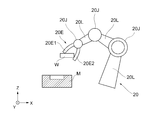
- 2 and 3 show a schematic diagram of a robot arm that holds an object.
- the robot system 100 includes a robot arm 20, a control device 10 for controlling the robot arm 20, a display device 60, and an input device 62.
- the robot system 100 according to the present embodiment holds an insert component W which is a fitting object (an example of an "object"), and this fitting object is an fitting object (an example of an "assembly site"). The fitting operation of assembling to the assembling portion of the mold M is executed.
- the robot arm 20 holds an object, brings it close to the assembly site, and then performs an operation including a copying operation in which the object is brought into contact with the assembly site to imitate.
- the robot arm 20 is, for example, a vertical articulated robot, which includes a base (not shown), a plurality of links 20L, a plurality of joints 20J, and an end effector 20E. It includes a plurality of drive units 30, one or more series elastic actuators 40, and a pressure detection unit 50.
- the robot arm 20 is not limited to the vertical articulated robot, and may be, for example, a horizontal articulated robot device or a parallel link type robot device.
- the link 20L is composed of a rigid member, for example, a link 20L corresponding to a body rotatably attached to a base and a lower arm rotatably attached to the body.
- the link 20L corresponding to the portion, the link 20L corresponding to the upper arm portion rotatably attached to the lower arm portion, and the link 20L corresponding to the wrist portion rotatably attached to the upper arm portion (Not shown).
- the end effector 20E (an example of a "holding mechanism") has a function of holding an object.
- the end effector 20E is attached to the tip of a link 20L corresponding to a wrist portion, and is configured to be able to hold an object by sandwiching it with movable plates 20E1 and 20E2 that are opened and closed by an actuator, for example.
- the end effector 20E is not limited to this, and for example, a negative pressure is generated in the suction pad based on a plurality of suction pads for holding the surface of the object and a control signal transmitted from the control device 10. It may be provided with an actuator that causes the object to be moved, or may hold an object by electromagnetic force.
- the robot arm 20 shown as an example in the present embodiment can execute a copying operation by a driving mechanism that is distinguished from the holding mechanism.
- the end effector 20E does not necessarily have to be provided with a sensor for acquiring contact pressure or torque for the six axes.
- the robot arm 20 includes a series elastic actuator 40 provided at at least one joint 20J connecting the links 20L to each other.
- the series elastic actuator 40 is mounted on all the joints 20J of the robot arm 20.
- the series elastic actuator 40 (an example of a "flexible drive mechanism") is composed of, for example, a drive unit 42 and an elastic body 44 connected to the drive unit 42.
- the drive unit 42 is composed of, for example, a servomotor.
- the elastic body 44 is composed of, for example, a mechanical spring (for example, a plate-shaped spring). Since the plate-shaped spring has high torsional rigidity, it is suitable for the copying operation in the present embodiment.
- the power output from the drive unit 42 in the series elastic actuator 40 is transmitted to the link 20L on the output side via the elastic body 44 and is rotated.
- the series elastic actuator 40 according to the present embodiment includes a sensor (not shown) for acquiring the displacement amount of the mechanical spring.
- the pressure detection unit 50 detects the contact pressure when the object by the robot arm 20 is brought into contact with the assembly site. By controlling the contact pressure detected by the pressure detection unit 50 to be substantially constant, it is possible to perform a copy operation that imitates the object to be assembled.
- the control device 10 is configured to perform mechanical compliance control for controlling impedance based on the spring constant and the amount of displacement of the mechanical spring.
- the series elastic actuator 40 may be connected to the drive shaft of the servomotor, which is the drive unit 42, and may include a gear that transmits power to the mechanical spring. Further, the series elastic actuator 40 may include a damper mechanism that cushions the impact based on the viscosity and a clutch mechanism for switching the transmission of power.
- a viscous body such as a damper mechanism having viscosity
- a viscosity constant is added as a parameter to the equation of motion. For example, an equation of motion is established in which the value obtained by multiplying the viscosity constant by the time change of the link angle is taken as the torque.
- a link 20L other than the link 20L driven by the series elastic actuator 40 such a link 20L is driven by, for example, a drive unit 30 composed of a servomotor.
- the drive unit 30 rotates the link 20L on the output side around the drive shaft.
- the drive unit 30 may be mounted on the link 20L.
- the control device 10 includes a control command acquisition unit 12, a copy operation execution unit 14, an error detection unit 16, and a determination unit 18.
- the control command acquisition unit 12 acquires control commands for controlling the servomotor corresponding to each drive unit 30 of the robot arm 20 and the servomotor of the series elastic actuator 40.
- This control command is based on the start position and the posture at that time of the reference position of the robot arm 20 (for example, the center point of the end effector 20E corresponding to the hand position), the target position, the posture at that time, and the target position. It is generated based on various information including an allowable range in which the reference position of the robot arm 20 can be separated from the target position and a movement path connecting the start position and one or a plurality of target positions.
- the control command acquisition unit 12 acquires a control command for controlling each servomotor for moving the reference position according to the path by arithmetic processing or the like. For example, the control command acquisition unit 12 calculates the rotation angle of each servomotor for the reference position to be located on the path by inverse kinematics calculation (inverse kinematics), and generates a control command based on this.
- inverse kinematics inverse kinematics
- the copy operation execution unit 14 elastically deforms the series elastic actuator 40 of the robot arm 20 to cause the robot arm 20 to perform a copy operation in which the object is brought into contact with the assembly portion to be imitated.
- the copying operation means moving the object relative to the assembly site while bringing the object into contact with the assembly site.
- the relative movement is not limited to the translational movement, but includes the rotational movement of the object relative to the assembly site.
- the copying operation executing unit 14 is configured to elastically deform the elastic body 44 of the series elastic actuator 40 so that the contact pressure detected by the pressure detecting unit 50 is substantially constant or within a predetermined range. .. As a result, it is possible to carry out the assembling work on the object or the assembling site while suppressing damage such as galling.
- the error detection unit 16 detects error information based on the measured value of the contact pressure detected by the pressure detection unit 50 during the operation of the robot arm 20. For example, when the pressure detection unit 50 determines that the measured value of the contact pressure during the copying operation exceeds the threshold value, the error detection unit 16 determines that there is some defect in the object or the assembly site and detects the error information. do.
- the determination unit 18 determines the operation of the robot arm 20 after the error based on the error content of the error information detected by the error detection unit 16. Specifically, if the first error information occurs for the first time during the copying operation, the determination unit 18 causes the robot arm 20 to perform the copying operation again after exchanging the object, and on the other hand, the object has already been selected. If it is the second error information generated during the re-copying operation generated after the replacement, the operation of the robot arm 20 is stopped. If it is the first error information, there is a high possibility that the object itself is abnormal, such as foreign matter adhering to the object. Therefore, the error problem can be solved by causing the robot arm 20 to perform the copying operation again. there is a possibility.
- the second error information is not limited to the second error, and may be the third or later. Information (particularly, second error information) according to the type of error determined by the determination unit 18 of the control device 10 may be notified to the user by displaying it on the display device 60.
- the control device 10 includes, for example, an arithmetic element that is a processor such as a CPU (Central Processing Unit) and a GPU (Graphical Processing Unit), a SRAM (Static Random Access Memory), a DRAM (Dynamic Random Access Memory), and the like. It is possible to configure a computer equipped with a volatile storage element of the above, a non-volatile storage element such as a NOR flash memory, a NAND flash memory, and an HDD (Hard Disc Drive), and a communication means such as a bus connecting these.
- the non-volatile storage element stores, for example, a computer program for executing each process shown in the present embodiment.
- the volatile storage element temporarily stores at least a part of these computer programs, arithmetic processing results, and the like.
- at least a part of these arithmetic elements, non-volatile storage elements and the like may be installed in a remote place connected to a communication network such as the Internet.
- the arithmetic element may be configured to acquire a computer program or necessary data via a communication network.
- the control device 10, the robot arm 20, the display device 60, and the input device 62 are configured to be capable of transmitting and receiving information by wireless or wired communication means, respectively.
- a teaching device (not shown) for teaching the operation of the robot system 100 may be connected to the control device 10.
- the display device 60 and the input device 62 may be a computer including a display unit and an input unit, or may be integrally configured such as a touch panel or the like.
- an insert component W (an example of an “object”) is used as an example of a mold M (an example of an “assembly site”” in which a cylindrical recess is formed. )
- a mold M an example of an “assembly site” in which a cylindrical recess is formed.
- 2 and 3 are schematic views showing a state in which an object, which is an insert component W, is fitted into a recess of a mold M by a robot arm 20 in a side view and a top view.
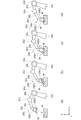
- FIGS. 4 (a) to 4 (d) show a series of flows of the operation method of the robot arm 20.
- the robot arm 20 has a link 20L corresponding to a body rotatably attached to the base and a lower arm rotatably attached to the body.
- the link 20L corresponding to the portion, the link 20L corresponding to the upper arm portion rotatably attached to the lower arm portion, and the link 20L corresponding to the wrist portion rotatably attached to the upper arm portion (Not shown), an end effector 20E that can be held by sandwiching the object between the movable plates 20E1 and 20E2, and a joint 20J that connects each link 20L.
- the series elastic actuator 40 is mounted on a joint 20J that connects the links 20L to each other.
- the insert component W is formed in a disk shape, for example.
- the cylindrical recess formed in the mold M is formed, for example, slightly larger than the diameter of the insert component W (for example, 50 ⁇ m larger).
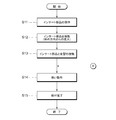
- the end effector 20E of the robot arm 20 holds the insert component W by sandwiching the upper surface and the side surface of the insert component W (S11 in FIG. 5).
- the robot arm 20 moves the insert component W and brings it closer to the recess of the mold M from an oblique direction (S12 in FIG. 5).
- the insert component W is tilted at a predetermined approach angle ⁇ (0 ° ⁇ ⁇ 90 °) with respect to the Z-axis direction, which is the insertion axis in the insertion direction when the insert component W is inserted into the recess of the mold M.
- the insert component W is brought closer to the recess of the mold M from the above direction.
- the approach angle ⁇ can be appropriately set according to, for example, the inclination angle of the insert component W held by the end effector 20E, the shapes of the recesses of the insert component W and the mold M, and the like.
- the robot arm 20 brings the side surface of the insert component W into contact with the corner of the open end of the recess of the mold M (S13 in FIG. 5).
- the robot arm 20 operates so as to allow the insert component W to enter the recess of the mold M while maintaining the state in which the side surface of the insert component W is in contact with the corner portion of the opening end of the recess of the mold M. Is executed (S14 in FIG. 5).
- the robot arm 20 performs a rotational operation in which the insert component W is relatively applied to the concave portion of the mold M about the Y axis with the side surface of the insert component in contact with the corner portion of the concave portion as a fulcrum. By doing so, the insert component W is further imitated with respect to the concave portion of the mold M.
- the robot arm 20 causes the insert component W to rotate by applying a rotational force around the Y axis until the insert component W becomes horizontal.
- the insert component W may be rotationally moved, or the insert component W may be simply subjected to rotational force without being rotationally moved.
- the possibility that the insert component W will protrude out of the recess of the mold M when the insert component W becomes horizontal is suppressed. Will be possible.
- the robot arm 20 presses the surface of the insert component W to fit the insert component W into the recess of the mold M (S15 in FIG. 5).
- the object held by the robot arm 20 is brought closer to the assembly site from an oblique direction by using the robot arm 20 having a flexible drive mechanism. Performs a copying operation that imitates an object against the assembly site. According to this, while suppressing damage to both the object and the assembling part, the object and the assembling part are brought into contact smoothly and easily, and the object and the assembling part are raised by the subsequent copying operation. Can be assembled with precision. Therefore, it becomes possible to automate the assembly work with high accuracy. Further, by using the robot arm 20 having a flexible drive mechanism, it is possible to prevent the surface of the object from being damaged even if the surface of the object is pressed.
- the insert component W is brought closer to the concave portion of the mold M from an oblique direction, but the present invention is not limited to such an embodiment and is oblique toward a position away from the concave portion of the mold M. It also includes a mode of approaching from the direction.
- a modified example of the present embodiment will be described below with reference to FIGS. 6 and 7.
- FIGS. 6 and 7 the position where the insert component W held by the robot arm 20 passes above the recess of the mold M in the X-axis direction is set as the target position.
- the insert component W may be brought close to the mold M and brought into contact with the insert component W from an oblique direction.
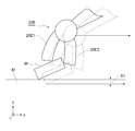
- FIG. 6 is a schematic diagram for explaining the difference between the target position and the actual position when the end portion of the insert component W comes into contact with the surface of the mold M.
- the end effector 20E and the insert component W held by the end effector 20E when the reference position is at the target position are shown by broken lines.
- the actual end effector 20E whose reference position is separated from the target position and the insert component W held by the end effector 20E are shown by solid lines.
- the insert component W held by the end effector 20E at the target position interferes with the mold M.
- the displacement amount D1 corresponds to the amount of elastic deformation of the elastic body 44 of the series elastic actuator 40.
- a force based on the displacement amount and the spring constant acts on the mold M from the insert component W.
- the robot arm 20 performs a copying operation.
- the robot arm 20 moves the insert component W toward the recess of the mold M in the X-axis direction indicated by the arrow in FIG. 6 while maintaining the state in which the insert component W is in contact with the mold M. Then, the side surface of the insert component W is brought into contact with the corner of the open end of the concave portion of the mold M shown in FIG.
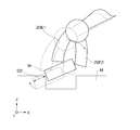
- FIG. 7 is a schematic view showing a target position in a scene where the side surface of the insert component comes into contact with the corner portion of the opening end of the recess of the mold M.
- the end effector 20E at the target position and the object held by the end effector 20E are shown by a broken line
- the actual end effector 20E and the object held by the end effector 20E are shown by a solid line.
- the insert component W held by the end effector 20E at the target position interferes with the mold M.
- the side surface of the insert component W comes into contact with the corner portion of the open end of the mold M.
- the displacement amount D2 corresponds to the amount of elastic deformation of the elastic body 44 of the series elastic actuator 40.
- a force based on the displacement amount and the spring constant acts from the object to the object.
- the force acting on the mold M from the insert component W may be increased to improve the stability of the insert component W.
- the robot arm 20 operates so as to allow the insert component W to enter the recess of the mold M while maintaining the state in which the side surface of the insert component W is in contact with the corner portion of the opening end of the recess of the mold M. To execute. For the subsequent processing, the contents described with reference to FIGS. 4 (b) to 4 (d) and FIG. 5 can be applied.
- the contents described with reference to FIG. 7 can be similarly applied to the copying operation (S14) of FIGS. 4 (b) and 5. That is, the copying operation according to the present embodiment includes moving the insert component W to a position where the insert component W interferes with the mold M. It should be noted that the contents described with respect to FIGS. 4 (a), 4 (b) and 4 (d) may be applied to each operation of FIGS. 8 (a), 8 (b) and 8 (d). can.
- the copying operation is a rotational operation around the Z axis, which is the insertion direction of the mold M into the concave portion of the mold M, when the insert component W is inserted into the concave portion of the mold M (see FIG. 8C).
- the other configurations can be applied by appropriately combining the contents described in any one of the above embodiments.
- the end effector 20E of the robot arm 20 holds the insert component W by sandwiching the upper surface and the side surface of the insert component W.
- the robot arm 20 moves the insert component W and brings it closer to the recess of the mold M from an oblique direction, and as shown in FIG. 8B, the side surface of the insert component W is brought to the mold M. Make contact with the corner of the open end of the recess.
- the robot arm 20 operates so as to allow the insert component W to enter the recess of the mold M while maintaining the state in which the side surface of the insert component W is in contact with the corner portion of the opening end of the recess of the mold M. To execute. At this time, as shown in FIG.
- the insert component W is rotated with respect to the recess of the mold M around the Z axis, which is the insertion direction of the mold M into the recess. At this time, the insert component W can be pressed in the Z-axis direction toward the recess while rotating the insert component W into the recess of the mold around the Z-axis. Since the robot arm 20 has a flexible drive mechanism, a predetermined contact pressure that suppresses damage to both is maintained in both the rotation operation around the Z axis and the pressurization operation in the Z axis direction. At the same time, the insert component W can be adjusted so that the outer shapes of the respective XY planes match the recesses of the mold M. After that, as shown in FIG. 8D, the robot arm 20 presses the surface of the insert component W to fit the insert component W into the recess of the mold M.
- the error detection unit 16 determines that the insert component W or the mold M has some defect. Then, the first error information is detected (S20 YES). As one aspect of detecting the first error information, for example, the pressure detecting unit 50 detects a measured value in which the contact pressure during the copying operation exceeds the threshold value, and the robot arm 20 performs the copying operation. Is to be interrupted.
- the determination unit 18 orders the robot arm 20 to replace the insert component W based on the error information of the error detection unit 16 being the first error information generated for the first time during the copying operation.
- the robot arm 20 is replaced with another insert component W (S21).
- the copy operation execution unit 14 controls the robot arm 20 to execute the copy operation again for another insert component W after replacement (S22).
- the second error information is detected (S23 YES).
- the pressure detecting unit 50 detects a measured value in which the contact pressure during the copying operation exceeds the threshold value, and the robot arm 20 performs the copying operation. Is to be interrupted.
- the mode of detecting the error information is not limited to the above-mentioned detection of the contact pressure, but may be based on the detection of the position information or the image information acquired by the image pickup apparatus, and the mode is limited. It is not something that will be done.
- the determination unit 18 operates the robot arm 20 including a copy operation with respect to the robot arm 20 based on the error information of the error detection unit 16 being the second error information generated during the copy operation again. Is stopped (S24).
- the second error information means that the imitation operation of the robot arm 20 does not proceed even if the insert component W is replaced. Therefore, the detection of the second error information means that there is a high possibility that a plurality of insert parts in the manufacturing lot unit are defective or that the mold M, which is the assembly site, is defective. However, since there is a high possibility that the error problem will not be solved even if the insert component W is replaced again, the robot arm 20 stops its operation.
- the operation of the robot arm 20 is stopped, a plurality of insert parts for each manufacturing lot are defective in the display device 60, or the mold M, which is an assembly site, is defective. Information such as the fact that it is likely to occur may be displayed.
- step S14 when the error information is not detected in step S20 (S20 NO) and when the error information is not detected in step S23 (S23 NO), the imitation operation (S14) of FIG. 5 is performed. Return and continue the imitation operation.
- the robot arm 20 automatically replaces the insert component W again. Since the operation of the robot arm 20 is stopped only when the imitation operation is executed and the second error information is detected, the manual work can be omitted as much as possible, and the automation of assembly by the robot arm can be improved.
- the operation method of the robot arm according to the embodiment of the present invention is an operation method of the robot arm in which an object is assembled to an assembly site by using a robot arm having a flexible drive mechanism. This includes bringing the object held by the robot arm closer to the assembled part from an oblique direction, and performing a copying operation to imitate the object with respect to the assembled part.
- the object held by the robot arm is brought closer to the assembling part from an oblique direction, and the object is brought to the assembling part.
- the object and the assembly site are brought into contact smoothly and easily while suppressing damage to both the object and the assembly site, and the object and the assembly site are brought into contact with each other by the copy motion. It can be assembled with high accuracy. Therefore, it becomes possible to automate the assembly work with high accuracy.
- the drive mechanism includes a series elastic actuator.
- the copying operation includes elastically deforming the elastic body of the series elastic actuator while causing the object to copy to the assembly site.
- the elastic body of the series elastic actuator is composed of a plate-shaped spring.
- the drive mechanism comprises at least one of a ferrofluid, a mechanical spring, an air spring, a magnetic spring and a vane motor to impart flexibility.
- the copying operation includes moving the object to a position where the object interferes with the assembly site.
- the copying motion includes performing a rotational motion in the direction of insertion into the assembly site when the object is made to enter the assembly site.
- the robot arm replaces the object with another object based on the first error information detected during the copying operation, and another object held by the robot arm is attached to the assembly site. This includes performing a re-copying operation for assembling, and stopping the operation based on the second error information detected during the re-copying operation.
- the robot system has a robot arm having a flexible drive mechanism and a holding mechanism capable of holding an object, and a control for assembling the object to an assembly site using the robot arm.
- the control device is provided with a device, and the control device performs a copying operation of bringing the object held by the robot arm closer to the assembled part from an oblique direction and making the object imitate the assembled part. It is configured to do.
- the program according to the embodiment of the present invention is a program executed in a computer for assembling an object to an assembly site by using a robot arm having a flexible drive mechanism, and the robot arm is attached to the computer.
- the object held by the robot is brought closer to the assembly site from an oblique direction, and the imitation operation of making the object imitate the assembly site is executed.
- the present invention holds a flange (an example of an “object”) on which a through hole is formed.
- the work of assembling the flange to the shaft by making the wall surface of the through hole follow the surface of the shaft (an example of "object") so that the shaft penetrates the through hole, and the printed wiring board to be inspected ("object").
- the wall surface of the through hole is made to follow the surface of the inspection instrument so that the rod-shaped inspection instrument (an example of the “object”) penetrates the through hole formed in the printed wiring board. It can be applied to various applications such as inspecting the inner diameter of a through hole and assembling an optical component such as a lens module (an example of an "object”) to a precision instrument (an example of an "object”). be.
- ⁇ with flexibility
- Elasticity refers to the property of deforming when stress is applied and returning to the original state when stress is removed, and is sometimes expressed by the term flexibility, which indicates the ease of elastic deformation.
- Viscosity refers to the property of generating stress that equalizes the flow velocity of a fluid. Magnetic fluids, mechanical springs (leaf springs, torsion coil springs), air springs, magnetic force springs, vane motors, variable dampers using electric viscous fluids whose viscosity can be adjusted according to the applied voltage, to impart viscosity and elasticity. Etc. may be used.
Landscapes
- Engineering & Computer Science (AREA)
- Human Computer Interaction (AREA)
- Robotics (AREA)
- Mechanical Engineering (AREA)
- Manipulator (AREA)
Abstract
柔軟性を備えた駆動機構40を有するロボットアーム20を用いて対象物Wを組付部位Mに組み付ける、ロボットアーム20の動作方法であって、ロボットアーム20によって保持された対象物Wを、組付部位Mに対して斜め方向から近づけること、対象物Wを組付部位Mに対して倣わせる倣い動作を行うことを含む。
Description
本発明は、ロボットアームの動作方法、ロボットシステム、教示方法及びプログラムに関する。
近年、ロボットアームを用いて部品等の対象物を保持し、目標物の所定位置に組み付けることが行われている。例えば、ロボットアームを用いて嵌合物を保持し、目標物に嵌合させる試みが行われている。
特許文献1には、ロボットアームにより移動させた第1対象物を、挿入部を有する第2対象物に接触させた後、力の検出結果に基づいてロボットアームにより第1対象物を回転させつつ並進させて、第1対象物を挿入部に挿入するロボットが開示されている。この構成によれば、特に、第1対象物の挿入方向に対して垂直な方向の断面形状が真円ではない場合でも迅速に第1対象物を第2対象物の挿入部に挿入することができる。
特許文献2には、自動組立装置のベースと可動部との距離変化に基づいて挿入部材と受け部材との予備嵌合の成否を判定し、失敗した場合には、挿入部材を退避させ所定量だけ回転させた後、再び予備嵌合動作を実行することが開示されている。この構成によれば、嵌合方向に直交する方向における断面が非円形の挿入部材及び受入部材においても、これらの部材を支障なく嵌め合わせることができる。
しかしながら、いずれの構成においても、ロボットアームや組立装置における接触圧力や距離変化に基づいて嵌合作業を行うため、高精度な位置決めが設けられるほか、制御遅れによって対象物や組付部位を損傷させてしまう可能性がある。特に、嵌合のクリアランスが極めて小さい場合においては嵌合自体が困難である。
本発明のある態様の例示的な目的の一つは、高精度な組付作業を自動化することが可能である、ロボットアームの動作方法、ロボットシステム及びプログラムを提供することにある。
上記課題を解決するため、本発明の一実施形態に係るロボットアームの動作方法は、柔軟性を備えた駆動機構を有するロボットアームを用いて対象物を組付部位に組み付ける、ロボットアームの動作方法であって、ロボットアームによって保持された対象物を、組付部位に対して斜め方向から近づけること、対象物を組付部位に対して倣わせる倣い動作を行うことを含む。
上記態様によれば、柔軟性を備える駆動機構を有するロボットアームを用いて、ロボットアームによって保持された対象物を、組付部位に対して斜め方向から近づけて、対象物を組付部位に対して倣わせる倣い動作を行うため、対象物及び組付部位の両者が損傷することを抑制しつつ、対象物と組付部位を円滑かつ容易に接触させ、倣い動作によって対象物及び組付部位を高精度に組み付けることができる。したがって、高精度な組付作業を自動化することが可能になる。
本発明のさらなる別の態様は、ロボットシステムである。このシステムは、柔軟性を備える駆動機構と対象物を保持可能な保持機構とを有するロボットアームと、ロボットアームを用いて対象物を組付け部位に組み付けるための制御装置とを備え、制御装置は、ロボットアームによって保持された対象物を、組付部位に対して斜め方向から近づけること、対象物を組付部位に対して倣わせる倣い動作を行うことを実行するように構成されている。
本発明のさらなる別の態様は、教示方法である。この教示方法は、柔軟性を備える駆動機構と対象物を保持可能な保持機構とを有するロボットアームと、ロボットアームを用いて対象物を組付部位に組み付けるための制御装置と、を備えるロボットシステムに動作教示する教示方法であって、ロボットアームによって保持された対象物を、組付部位に対して斜め方向から近づけること、対象物を組付部位に対して倣わせる倣い動作を行うこと、をロボットシステムに実行させるための教示を行う。
教示は、オンラインティーチング又はオフラインティーチング等の方法により実行することが可能である。
本発明のさらなる別の態様は、プログラムである。このプログラムは、柔軟性を備えた駆動機構を有するロボットアームを用いて対象物を組付部位に組み付けるためにコンピュータにおいて実行されるプログラムであって、コンピュータに、ロボットアームによって保持された対象物を、組付部位に対して斜め方向から近づけること、対象物を組付部位に対して倣わせる倣い動作を行うことを実行させる。
なお、以上の構成要素の任意の組み合わせや本発明の構成要素や表現を、方法、装置、システム、コンピュータプログラム、データ構造、記録媒体などの間で相互に置換したものもまた、本発明の態様として有効である。
本発明によれば、高精度な組付作業を自動化することができる。
以下、図面を参照しつつ、発明の実施形態を通じて本発明を説明するが、以下の実施形態は特許請求の範囲に係る発明を限定するものではなく、また、実施形態の中で説明されている特徴の組み合わせのすべてが発明の解決手段に必須であるとは限らない。各図面に示される同一又は同等の構成要素、部材、処理には、同一の符号を付するものとし、適宜重複した説明は省略する。
図1は本発明の一実施形態に係るロボットシステムの機能ブロックを示す図である。図2及び図3は対象物を保持するロボットアームの模式図を示している。
図1に示すように、ロボットシステム100は、ロボットアーム20と、ロボットアーム20を制御する制御装置10と、表示装置60と、入力装置62とを備えている。本実施形態に係るロボットシステム100は、嵌合物(「対象物」の一例)であるインサート部品Wを保持し、この嵌合物を嵌合対象物(「組付部位」の一例)である金型Mの組付部位に組み付ける嵌合動作を実行する。
ロボットアーム20は、対象物を保持し、これを組付部位に向かって接近させた後、対象物を組付部位に接触させて倣わせる倣い動作を含む動作を実行する。図2及び図3に示すように、ロボットアーム20は、例えば、垂直多関節ロボットであり、ベース(図示しない)と、複数のリンク20Lと、複数のジョイント20Jと、エンドエフェクタ20Eと、一又は複数の駆動部30と、一又は複数の直列弾性アクチュエータ40と、圧力検出部50とを備える。但し、ロボットアーム20は、垂直多関節ロボットに限られることはなく、例えば、水平多関節型ロボット装置、パラレルリンク型ロボット装置であってもよい。
リンク20Lは、剛性を有する部材から構成されており、例えば、ベースに対して回動可能に取り付けられた胴部に相当するリンク20Lと、胴部に対して回動可能に取り付けられた下腕部に相当するリンク20Lと、下腕部に対して回動可能に取り付けられた上腕部に相当するリンク20Lと、上腕部に対して回動可能に取り付けられた手首部に相当するリンク20L(図示しない)とを備える。
エンドエフェクタ20E(「保持機構」の一例)は、対象物を保持する機能を有する。エンドエフェクタ20Eは、手首部に相当するリンク20Lの先端に取り付けられており、例えば、アクチュエータによって開閉する可動プレート20E1及び20E2によって対象物を挟んで保持可能に構成されている。但し、エンドエフェクタ20Eは、これに限られるものではなく、例えば、対象物の表面を保持するための複数の吸着パッドと制御装置10から送信される制御信号に基づいて吸着パッドに負圧を発生させるアクチュエータを備えるものや、或いは、電磁力で対象物を保持するものであってもよい。本実施形態に一例として示されるロボットアーム20は、保持機構とは区別される駆動機構により倣い動作を実行することができる。なお、エンドエフェクタ20Eには必ずしも接触圧力又はトルクを6軸について取得するためのセンサが設けられていなくてもよい。
本実施形態に係るロボットアーム20は、リンク20L同士を接続する少なくとも一つのジョイント20Jに設けられた直列弾性アクチュエータ40を備えている。例えば、直列弾性アクチュエータ40は、ロボットアーム20の全てのジョイント20Jに搭載されている。
直列弾性アクチュエータ40(「柔軟性を備えた駆動機構」の一例)は、例えば、駆動部42と、駆動部42に接続される弾性体44とから構成される。駆動部42は、例えば、サーボモータから構成される。弾性体44は、例えば、機械ばね(例えば板状ばね)から構成される。板状ばねは高いねじり剛性を有するため、本実施形態における倣い動作に適している。直列弾性アクチュエータ40において駆動部42から出力される動力は、弾性体44を介して、出力側のリンク20Lに伝達し、これを回動させる。更に、本実施形態に係る直列弾性アクチュエータ40は、機械ばねの変位量を取得するためのセンサ(図示しない)を備えている。
圧力検出部50は、ロボットアーム20による対象物を組付部位に接触させたときの接触圧力を検出する。圧力検出部50によって検出された接触圧力を実質的に一定に制御することによって対象物を組付部位に倣わせる倣い動作を行うことができる。
以上のようなロボットアーム20の構成によれば、柔軟性を備えた駆動機構に相当する直列弾性アクチュエータ40によって駆動される部分の慣性、質量及び長さ、外力並びに弾性体44である機械ばねのばね定数をパラメータとする運動方程式が成立する。このため、制御装置10は、機械ばねのばね定数及び変位量に基づいて、インピーダンスを制御するメカニカル・コンプライアンス制御を行うように構成される。
なお、直列弾性アクチュエータ40は、駆動部42であるサーボモータの駆動軸に接続され、動力を機械ばねに伝達するギヤを備えていてもよい。更に、直列弾性アクチュエータ40は、粘性に基づいて衝撃を緩和させるダンパ機構及び動力の伝達をスイッチするためのクラッチ機構を備えてもよい。粘性を有するダンパ機構等の粘性体を付与する場合、運動方程式には、粘性定数がパラメータとして加えられる。例えば、粘性定数にリンク角度の時間変化を乗じた値をトルクとして考慮された運動方程式が成立する。
直列弾性アクチュエータ40によって駆動されるリンク20L以外のリンク20Lが存在する場合、このようなリンク20Lは、例えば、サーボモータから構成される駆動部30によって駆動される。駆動部30は、出力側のリンク20Lを駆動軸回りに回動させる。駆動部30は、リンク20Lに搭載されていてもよい。以上のような構成により、複数のリンク20Lを回動させることが可能になるため、リンク20Lの先端に相当するエンドエフェクタ20Eの位置及び姿勢を変化させることが可能となる。
図1に示すように、制御装置10は、制御命令取得部12と、倣い動作実行部14と、エラー検知部16と、判断部18とを備えている。制御命令取得部12は、ロボットアーム20の各駆動部30に相当するサーボモータ及び直列弾性アクチュエータ40のサーボモータを制御するための制御命令を取得する。この制御命令は、ロボットアーム20の基準となる位置(例えば、手先位置に相当するエンドエフェクタ20Eのセンターポイント。)の開始位置及びその時の姿勢と、目標位置及びその時の姿勢と、目標位置を基準として目標位置からロボットアーム20の基準位置が離れることができる許容範囲と、開始位置と一つ又は複数の目標位置を結ぶ移動経路とを含む各種情報に基づいて生成される。後述するように、本実施形態に係るロボットアームの動作方法においては、ロボットアーム20によって保持される対象物が組付部位と干渉するような経路を取得することが可能である。制御命令取得部12は、基準位置を経路に従って移動させるための各サーボモータを制御するための制御命令を演算処理等により取得する。例えば、制御命令取得部12は、逆運動学演算(インバースキネマティクス)により、基準位置が経路上に位置するための各サーボモータの回転角度を算出し、これに基づいて制御命令を生成する。
倣い動作実行部14は、ロボットアーム20の直列弾性アクチュエータ40を弾性変形させることによって、ロボットアーム20が対象物を組付部位に接触させて倣わせる倣い動作を実行させる。倣い動作とは、対象物を組付部位に接触させながら、対象物を組付部位に対して相対的に移動させることをいう。ここで、相対的に移動させることは、並進移動に限られず、組付部位に対して対象物を相対的に回転移動させることを含む。倣い動作実行部14は、圧力検出部50によって検出される接触圧力が実質的に一定値又は所定範囲内となるように、直列弾性アクチュエータ40の弾性体44を弾性変形させるように構成されている。これにより、対象物又は組付部位に対して、かじりなどの損傷を抑制しつつ組付作業を実行することができる。
エラー検知部16は、ロボットアーム20の動作中に圧力検出部50が検出した接触圧力の測定値に基づいてエラー情報を検知する。例えば、圧力検出部50が、倣い動作中の接触圧力の測定値がしきい値を超える場合、エラー検知部16は、対象物又は組付部位に何らかの欠陥があると判断してエラー情報を検知する。
判断部18は、エラー検知部16が検知したエラー情報のエラー内容に基づいて、ロボットアーム20のエラー後の動作を判断する。具体的には、判断部18は、倣い動作中に初めて発生した第1エラー情報であれば、ロボットアーム20に対象物を交換した後に再度の倣い動作を実行させ、他方で、対象物を既に交換した後に発生した再度の倣い動作中に発生した第2エラー情報であれば、ロボットアーム20の動作を停止する。第1エラー情報であれば、対象物に異物が付着している等の対象物単体の異常である可能性が高いため、ロボットアーム20に再度の倣い動作を実行させることでエラー問題が解消する可能性がある。他方で、第2エラー情報であれば、対象物の製造ロット単位又は組付部位自体の異常である可能性が高いため、対象物を交換してもエラー問題が解消しない可能性が高い。したがって、このような場合、ロボットアーム20の動作を停止させる。なお、第2エラー情報は、エラー回数が2回目であることに限らず、3回目以降であってもよい。制御装置10の判断部18によって判断されたエラーの種類に応じた情報(特に第2エラー情報)は、表示装置60に表示することによってユーザに報知するようにしてもよい。
ハードウェア構成に関し、制御装置10は、例えば、CPU(Central Processing Unit)、GPU(Graphical Processing Unit)等のプロセッサである演算素子と、SRAM(Static Random Access Memory)、DRAM(Dynamic Random Access Memory)等の揮発性記憶素子と、NORフラッシュメモリ、NANDフラッシュメモリ、HDD(Hard Disc Drive)等の不揮発性記憶素子と、これらを接続するバス等の通信手段を備えるコンピュータから構成することが可能である。不揮発性記憶素子には、例えば、本実施形態に示される各処理を実行するためのコンピュータプログラムが格納されている。揮発性記憶素子は、これらコンピュータプログラムの少なくとも一部及び演算処理結果等を一時的に記憶する。但し、これら演算素子、不揮発性記憶素子等の少なくとも一部は、インターネット等の通信ネットワークに接続された遠隔地に設置されていてもよい。例えば、演算素子は、通信ネットワークを介して、コンピュータプログラム又は必要なデータを取得するように構成されてもよい。
制御装置10、ロボットアーム20、表示装置60及び入力装置62は、それぞれ無線又は有線による通信手段によって情報の送受信が可能に構成されている。なお、制御装置10には、ロボットシステム100に動作教示するための教示装置(図示しない)が接続されてもよい。表示装置60及び入力装置62は、表示部及び入力部を備えるコンピュータであってもよいし、タッチパネル等のように一体として構成されていてもよい。
次に、本実施形態に係るロボットアーム20の動作方法の一例として、インサート部品W(「対象物」の一例)を、円筒状の凹部が形成された金型M(「組付部位」の一例)に嵌合する方法について説明する。図2及び図3は、ロボットアーム20によってインサート部品Wである対象物を金型Mの凹部に嵌合する様子を側面視及び上面視で示す模式図である。また、図4(a)~図4(d)はロボットアーム20の動作方法の一連の流れを示したものである。各図において説明の便宜上、垂直方向をZ軸方向とし、水平方向をX軸方向及びY軸方向とする座標系を示している。以下の説明では、インサート部品Wが金型Mの凹部に挿入するときの挿入方向の挿入軸はZ軸方向と一致している。
図2及び図3に示されるように、ロボットアーム20は、ベースに対して回動可能に取り付けられた胴部に相当するリンク20Lと、胴部に対して回動可能に取り付けられた下腕部に相当するリンク20Lと、下腕部に対して回動可能に取り付けられた上腕部に相当するリンク20Lと、上腕部に対して回動可能に取り付けられた手首部に相当するリンク20L(図示しない)と、対象物を可動プレート20E1及び20E2で挟むことにより保持可能なエンドエフェクタ20Eと、各リンク20Lを接続するジョイント20Jを備えている。例えば、直列弾性アクチュエータ40は、各リンク20L同士を接続するジョイント20Jに搭載されている。言い換えれば、X軸、Y軸及びZ軸の各並進力成分と、それら3軸のそれぞれの軸周りの回転力成分との6軸の全ての駆動機構が直列弾性アクチュエータ40を備えている。
インサート部品Wは、例えば、円板状に形成されている。金型Mに形成される円筒状の凹部は、例えば、インサート部品Wの直径よりも僅かに大きく(例えば、50μm大きく)形成されている。
従来、このような対象物の嵌合をロボットアーム20によって行うことは困難であった。対象物の側面をエンドエフェクタ20Eで挟んで保持する場合、エンドエフェクタ20Eが組付部位と干渉しないように、対象物である円板を凹部の直上に移動させた後、保持を解除して、対象物を落下させる必要がある。しかしながら、対象物と凹部との間隙が小さい場合、対象物が僅かに傾いただけであっても、対象物を凹部に挿入することができない。
これに対して、本開示に示されるロボットアーム20の動作方法によれば、高精度な組付作業を自動化することができる。
ここで、図4(a)~図4(d)及び図5を参照しつつ、具体的なプロセスについて以下に説明する。図4(a)に示されるように、ロボットアーム20のエンドエフェクタ20Eは、インサート部品Wの上面と側面を挟むことによりインサート部品Wを保持する(図5のS11)。次いで、ロボットアーム20は、インサート部品Wを移動させ、金型Mの凹部に対して斜め方向から近づける(図5のS12)。具体的には、インサート部品Wが金型Mの凹部に挿入するときの挿入方向の挿入軸であるZ軸方向に対して、所定の進入角度θ(0°<θ<90°)で傾斜させた方向から、インサート部品Wを金型Mの凹部に近づける。進入角度θは、例えば、エンドエフェクタ20Eによって保持されたインサート部品Wの傾斜角度やインサート部品W及び金型Mの凹部のそれぞれの形状などに応じて適宜設定することができる。インサート部品Wを金型Mの凹部に対して斜め方向から近づけて所定の接触圧力で接触させることによって、インサート部品W及び金型Mの両者を損傷させることなく倣い動作を開始させることができる。こうしたロボットアーム20によるインサート部品Wの斜め方向からの接近は、制御装置10の制御命令取得部12が取得した制御命令に基づいて行われる。
図4(b)に示されるように、ロボットアーム20は、インサート部品Wの側面を、金型Mの凹部の開口端の角部に接触させる(図5のS13)。次いで、ロボットアーム20は、インサート部品Wの側面が金型Mの凹部の開口端の角部に接触した状態を維持したまま、インサート部品Wを金型Mの凹部内に入り込ませるように倣い動作を実行する(図5のS14)。その後、ロボットアーム20は、凹部の角部に接触しているインサート部品の側面を支点として、インサート部品Wを金型Mの凹部に対して相対的にY軸周りに回転力を与える回転動作をさせることにより、インサート部品Wを金型Mの凹部に対してさらに倣わせる。
図4(c)に示されるように、ロボットアーム20は、インサート部品Wが水平になるまでインサート部品WをY軸周りに回転力を与える回転動作をさせる。この場合、インサート部品Wを回転移動させてもよいし、あるいは回転移動させずに回転力を与えるだけでもよい。このように、インサート部品Wの側面を凹部に接触させて回転動作をさせることによって、インサート部品Wが水平になったとき、インサート部品Wが金型Mの凹部の外にはみ出る可能性を抑制することが可能になる。
その後、図4(d)に示されるように、ロボットアーム20は、インサート部品Wの表面を押圧してインサート部品Wを金型Mの凹部に嵌合させる(図5のS15)。
以上のとおり、本実施形態によれば、柔軟性を備える駆動機構を有するロボットアーム20を用いて、ロボットアーム20によって保持された対象物を、組付部位に対して斜め方向から近づけて、対象物を組付部位に対して倣わせる倣い動作を行う。これによれば、対象物及び組付部位の両者を損傷することを抑制しつつ、対象物と組付部位の接触を円滑かつ容易に行い、その後の倣い動作によって対象物及び組付部位を高精度に組み付けることができる。したがって、高精度な組付作業を自動化することが可能になる。また、柔軟性を備える駆動機構を有するロボットアーム20を用いることにより、対象物の表面を押圧しても、対象物の表面が傷つくことを抑制することが可能になる。
上記実施形態では、インサート部品Wを金型Mの凹部に向かって斜め方向から近づけたが、本発明はこのような態様に限定されず、金型Mの凹部とは離れた位置に向かって斜め方向から近づける態様も含む。以下に図6及び図7を参照しつつ、本実施形態にかかる変形例を説明する。
具体的には、図6及び図7に示すように、ロボットアーム20によって保持されたインサート部品Wを、X軸方向において、金型Mの凹部の上方を通過した位置を目標位置としてその位置に向かって、斜め方向からインサート部品Wを金型Mに近づけて接触させてもよい。ここで、図6は、インサート部品Wの端部が金型Mの表面と接触する場面における目標位置と実際の位置の相違を説明するための模式図である。同図において、基準位置が目標位置にある時のエンドエフェクタ20E及びこれに保持されるインサート部品Wは、破線で示されている。一方で、基準位置が目標位置から離間している実際のエンドエフェクタ20E及びこれに保持されるインサート部品Wは、実線で示されている。破線で示されるように、目標位置において、エンドエフェクタ20Eに保持されるインサート部品Wは、金型Mと干渉する。実際は、目的物が存在するために、インサート部品Wの端部が金型Mの表面と接触する。変位量D1は、直列弾性アクチュエータ40の弾性体44が弾性変形した量に相当する。このとき、変位量及びばね定数に基づいた力が、インサート部品Wから金型Mに作用する。インサート部品Wの端部が金型Mの表面に接触した後、ロボットアーム20は、倣い動作を実行する。具体的には、ロボットアーム20は、インサート部品Wを金型Mに接触させた状態を維持しながら、インサート部品Wを金型Mの凹部に向かって図6の矢印で示すX軸方向に移動させ、図7に示す金型Mの凹部の開口端の角部にインサート部品Wの側面を接触させる。
ここで、図7は、インサート部品の側面が金型Mの凹部の開口端の角部と接触する場面における目標位置を示す模式図である。同図においても、目標位置におけるエンドエフェクタ20E及びこれに保持される対象物は、破線で示され、実際のエンドエフェクタ20E及びこれに保持される対象物は、実線で示されている。破線で示されるように、目標位置において、エンドエフェクタ20Eに保持されるインサート部品Wは、金型Mと干渉する。しかしながら、実際は、金型Mが存在するために、インサート部品Wの側面が金型Mの開口端の角部と接触する。変位量D2は、直列弾性アクチュエータ40の弾性体44が弾性変形した量に相当する。このとき、変位量及びばね定数に基づいた力が、対象物から目的物に作用する。なお、変位量D2>変位量D1となるように、目標位置を定めることにより、インサート部品Wから金型Mに作用する力を大きくし、インサート部品Wの安定性を高めてもよい。次いで、ロボットアーム20は、インサート部品Wの側面が金型Mの凹部の開口端の角部に接触した状態を維持したまま、インサート部品Wを金型Mの凹部内に入り込ませるように倣い動作を実行する。その後の処理は、図4(b)~図4(d)及び図5を用いて説明した内容を適用することができる。なお、図7を用いて説明した内容は、図4(b)及び図5の倣い動作(S14)においても、同様に適用され得るものである。すなわち、本実施形態に係る倣い動作は、インサート部品Wが金型Mに干渉する位置にインサート部品Wを移動させることを含む。なお、図8(a)、図8(b)及び図8(d)の各動作は、図4(a)、図4(b)及び図4(d)について説明した内容を適用することができる。
次に、図8(a)~図8(d)を参照しつつ、ロボットアーム20の動作方法のさらなる変形例を説明する。以下に示す例では、倣い動作が、インサート部品Wを金型Mの凹部へ進入させる際に、金型Mの凹部への挿入方向であるZ軸周りの回転動作(図8(c)参照)を含む点が異なっており、その他の構成は上記実施形態のいずれかの態様で説明した内容を適宜組み合わせて適用することができる。
具体的には、まず、図8(a)に示されるように、ロボットアーム20のエンドエフェクタ20Eは、インサート部品Wの上面と側面を挟むことによりインサート部品Wを保持する。次いで、ロボットアーム20は、インサート部品Wを移動させ、金型Mの凹部に対して斜め方向から近づけて、図8(b)に示されるように、インサート部品Wの側面を、金型Mの凹部の開口端の角部に接触させる。こうして、ロボットアーム20は、インサート部品Wの側面が金型Mの凹部の開口端の角部に接触した状態を維持したまま、インサート部品Wを金型Mの凹部内に入り込ませるように倣い動作を実行する。このとき、図8(c)に示すように、インサート部品Wを金型Mの凹部に対して、金型Mの凹部への挿入方向であるZ軸周りに回転させる。このとき、インサート部品Wを金型の凹部へZ軸周りに回転させながら、凹部に向かってZ軸方向に加圧することができる。ロボットアーム20は柔軟性を備える駆動機構を有しているため、Z軸周りの回転動作及びZ軸方向の加圧動作のいずれにおいても、両者の損傷を抑制する程度の所定の接触圧力を維持しながら、インサート部品Wを金型Mの凹部に対してそれぞれのXY平面の外形が一致するように調整することができる。その後、図8(d)に示されるように、ロボットアーム20は、インサート部品Wの表面を押圧してインサート部品Wを金型Mの凹部に嵌合させる。
このような態様によれば、特に、インサート部品WのXY平面形状が非対称である場合でも、インサート部品Wを金型Mの凹部に高精度に組付けすることが可能となる。
次に、図9を参照しつつ、ロボットアーム20の動作方法の他の変形例を説明する。以下に示す例では、倣い動作中にエラーを検出した場合における動作が上記各実施形態とは異なっており、その他の動作は既に説明した内容を適用することができる。
ロボットアーム20がインサート部品Wを金型Mに接触させた後、ロボットアーム20の倣い動作が進行しなかった場合、エラー検知部16は、インサート部品W又は金型Mに何らかの欠陥があると判断して第1エラー情報を検知する(S20 YES)。第1エラー情報を検知する場合の一態様としては、例えば、圧力検出部50が、倣い動作中の接触圧力がしきい値を超える測定値を検出したことに基づいて、ロボットアーム20の倣い動作が中断することである。
次に、判断部18は、エラー検知部16のエラー情報が、倣い動作中に初めて発生した第1エラー情報であることに基づいて、ロボットアーム20に対してインサート部品Wを交換させるよう指令し、ロボットアーム20が別のインサート部品Wに交換する(S21)。その後、倣い動作実行部14は、交換後の別のインサート部品Wに対して再度の倣い動作を実行させるようロボットアーム20を制御する(S22)。
そして、インサート部品Wを交換した後の再度の倣い動作中に、再度、ロボットアーム20の倣い動作が進行しなかった場合、エラー検知部16は、インサート部品W又は金型Mに何らかの欠陥があると判断して第2エラー情報を検知する(S23 YES)。第2エラー情報を検知する場合の一態様としては、例えば、圧力検出部50が、倣い動作中の接触圧力がしきい値を超える測定値を検出したことに基づいて、ロボットアーム20の倣い動作が中断することである。なお、エラー情報を検知する場合の態様は、上記した接触圧力の検知によるもの限らず、位置情報の検出によるものや、撮像装置によって取得した画像情報によるものであってもよく、その態様は限定されるものではない。
その後、判断部18は、エラー検知部16のエラー情報が、再度の倣い動作中に発生した第2エラー情報であることに基づいて、ロボットアーム20に対して倣い動作を含むロボットアーム20の動作を停止する(S24)。第2エラー情報は、インサート部品Wを交換しても、なおロボットアーム20の倣い動作が進行しないことを意味している。したがって、第2エラー情報を検出したことは、製造ロット単位の複数のインサート部品が不良であること、又は、組付部位である金型Mに不良が発生している可能性が高いことを意味し、インサート部品Wを再度交換してもエラー問題が解消しない可能性が高いため、ロボットアーム20はその動作を停止する。この場合、制御装置10は、ロボットアーム20の動作が停止したことや、表示装置60に製造ロット単位の複数のインサート部品が不良であること、又は、組付部位である金型Mに不良が発生している可能性が高いことなどの情報を表示してもよい。
なお、図9において、ステップS20においてエラー情報が検出されなかった場合(S20 NO)、及び、ステップS23においてエラー情報が検出されなかった場合(S23 NO)、それぞれ図5の倣い動作(S14)に戻り、倣い動作を継続する。
上記実施形態によれば、ロボットアーム20の倣い動作が進行しなかった場合であっても、第1エラー情報の検知であれば、ロボットアーム20が自動的にインサート部品Wを交換して再度の倣い動作を実行し、第2エラー情報の検知によって初めてロボットアーム20の動作が停止するため、人手作業を可能な限り省略して、ロボットアームによる組付自動化の向上を図ることができる。
以上のとおり、本発明の一実施形態に係るロボットアームの動作方法は、柔軟性を備えた駆動機構を有するロボットアームを用いて対象物を組付部位に組み付ける、ロボットアームの動作方法であって、ロボットアームによって保持された対象物を、組付部位に対して斜め方向から近づけること、対象物を前記組付部位に対して倣わせる倣い動作を行うことを含む。
これによれば、柔軟性を備える駆動機構を有するロボットアームを用いて、ロボットアームによって保持された対象物を、組付部位に対して斜め方向から近づけて、対象物を組付部位に対して倣わせる倣い動作を行うため、対象物及び組付部位の両者が損傷することを抑制しつつ、対象物と組付部位を円滑かつ容易に接触させ、倣い動作によって対象物及び組付部位を高精度に組み付けることができる。したがって、高精度な組付作業を自動化することが可能になる。
上記態様において、駆動機構は、直列弾性アクチュエータを備える。
上記態様において、倣い動作は、直列弾性アクチュエータの弾性体を弾性変形させながら、対象物を組付部位に対して倣わせることを含む。
上記態様において、直列弾性アクチュエータの弾性体は、板状ばねから構成されている。
上記態様において、駆動機構は、柔軟性を付与するための、磁性流体、機械ばね、空気ばね、磁力ばね及びベーンモータの少なくとも一つを備える。
上記態様において、倣い動作は、対象物が組付部位に干渉する位置に対象物を移動させることを含む。
上記態様において、倣い動作は、対象物を組付部位へ進入させる際に、組付部位への挿入方向に対する回転動作を行うことを含む。
上記態様において、倣い動作中に検知された第1エラー情報に基づいて、ロボットアームが対象物を別の対象物に交換すること、ロボットアームによって保持された別の対象物を、組付部位に組み付けるために再度の倣い動作を行うこと、再度の倣い動作中に検知された第2エラー情報に基づいて、ロボットアームが動作を停止することを含む。
本発明の一実施形態に係るロボットシステムは、柔軟性を備える駆動機構と対象物を保持可能な保持機構とを有するロボットアームと、ロボットアームを用いて対象物を組付け部位に組み付けるための制御装置とを備え、制御装置は、ロボットアームによって保持された対象物を、組付部位に対して斜め方向から近づけること、対象物を組付部位に対して倣わせる倣い動作を行うことを実行するように構成されている。
本発明の一実施形態に係るプログラムは、柔軟性を備えた駆動機構を有するロボットアームを用いて対象物を組付部位に組み付けるためにコンピュータにおいて実行されるプログラムであって、コンピュータに、ロボットアームによって保持された対象物を、組付部位に対して斜め方向から近づけること、対象物を前記組付部位に対して倣わせる倣い動作を行うことを実行させる。
本発明は、上記実施形態に限定されることなく種々に変形して適用することが可能である。上記実施形態及び変形例において説明したいずれかの態様は、当業者の理解に矛盾がない範囲で他の態様と組み合わせて適用することも可能である。
上記実施形態では、インサート部品Wが金型Mの凹部に嵌合する態様を説明したが、このほか、本発明は、貫通孔が形成されるフランジ(「対象物」の一例)を保持し、貫通孔をシャフトが貫通するように、貫通孔の壁面をシャフト(「目的物」の一例)の表面に倣わせて、フランジをシャフトに組み付ける作業や、検査対象となるプリント配線基板(「対象物」の一例)を保持し、プリント配線基板に形成された貫通孔を棒状の検査器具(「目的物」の一例)が貫通するように、貫通孔の壁面を検査器具の表面に倣わせて、貫通孔の内径を検査する作業や、レンズモジュール等の光学部品(「対象物」の一例)を精密機器(「目的物」の一例)に組み付ける作業等、様々な用途に適用することが可能である。
また、柔軟性を備えた駆動機構として、直列弾性アクチュエータの他、様々な駆動機構を利用することが可能である。ここで、「柔軟性を備えた」とは、弾性、粘性又は弾性及び粘性を備えていることをいう。弾性とは、応力を加えると変形し、応力を除去すると元に戻る性質をいい、弾性変形のしやすさを示す可撓性という言葉で表現される場合もある。粘性とは、流体の流動速度を一様化する応力を生じさせる性質をいう。粘性、弾性を付与するために、磁性流体、機械ばね(板ばね、ねじりコイルばね)、空気ばね、磁力ばね、ベーンモータ、印加電圧に応じて粘性を調整可能な電機粘性流体を用いた可変ダンパ、等を用いてもよい。
上記発明の実施形態を通じて説明された実施の態様は、用途に応じて適宜に組み合わせて、又は変更若しくは改良を加えて用いることができ、本発明は上述した実施形態の記載に限定されるものではない。そのような組み合わせ又は変更若しくは改良を加えた形態も本発明の技術的範囲に含まれ得ることが、特許請求の範囲の記載から明らかである。
10…制御装置、20…ロボットアーム、30…駆動部、40…直列弾性アクチュエータ、W…インサート部品、M…金型
Claims (11)
- 柔軟性を備えた駆動機構を有するロボットアームを用いて対象物を組付部位に組み付ける、ロボットアームの動作方法であって、
前記ロボットアームによって保持された前記対象物を、前記組付部位に対して斜め方向から近づけること、
前記対象物を前記組付部位に対して倣わせる倣い動作を行うこと
を含む、動作方法。 - 前記駆動機構は、直列弾性アクチュエータを備える、請求項1に記載の動作方法。
- 前記倣い動作は、前記直列弾性アクチュエータの弾性体を弾性変形させながら、前記対象物を前記組付部位に対して倣わせることを含む、請求項2に記載の動作方法。
- 前記直列弾性アクチュエータの前記弾性体は、板状ばねから構成されている、請求項3に記載の動作方法。
- 前記駆動機構は、前記柔軟性を付与するための、磁性流体、機械ばね、空気ばね、磁力ばね及びベーンモータの少なくとも一つを備える、請求項1に記載の動作方法。
- 前記倣い動作は、前記対象物が前記組付部位に干渉する位置に前記対象物を移動させることを含む、請求項1から5のいずれか一項に記載の動作方法。
- 前記倣い動作は、前記対象物を前記組付部位へ進入させる際に、前記組付部位への挿入方向に対する回転動作を行うことを含む、請求項1から6のいずれか一項に記載の動作方法。
- 前記倣い動作中に検知された第1エラー情報に基づいて、前記ロボットアームが前記対象物を別の対象物に交換すること、
前記ロボットアームによって保持された前記別の対象物を、前記組付部位に組み付けるために再度の倣い動作を行うこと、
前記再度の倣い動作中に検知された第2エラー情報に基づいて、前記ロボットアームが動作を停止すること
を含む、請求項1から7のいずれか一項に記載の動作方法。 - 柔軟性を備える駆動機構と対象物を保持可能な保持機構とを有するロボットアームと、
前記ロボットアームを用いて前記対象物を組付部位に組み付けるための制御装置と
を備え、
前記制御装置は、
前記ロボットアームによって保持された前記対象物を、前記組付部位に対して斜め方向から近づけること、
前記対象物を前記組付部位に対して倣わせる倣い動作を行うこと
を実行するように構成されている、ロボットシステム。 - 柔軟性を備える駆動機構と対象物を保持可能な保持機構とを有するロボットアームと、
前記ロボットアームを用いて前記対象物を組付部位に組み付けるための制御装置と、を備えるロボットシステムに動作教示する教示方法であって、
前記ロボットアームによって保持された前記対象物を、前記組付部位に対して斜め方向から近づけること、
前記対象物を前記組付部位に対して倣わせる倣い動作を行うこと、
を前記ロボットシステムに実行させるための教示を行う、
教示方法。 - 柔軟性を備えた駆動機構を有するロボットアームを用いて対象物を組付部位に組み付けるためにコンピュータにおいて実行されるプログラムであって、
前記コンピュータに、
前記ロボットアームによって保持された前記対象物を、前記組付部位に対して斜め方向から近づけること、
前記対象物を前記組付部位に対して倣わせる倣い動作を行うこと
を実行させるためのプログラム。
Priority Applications (1)
| Application Number | Priority Date | Filing Date | Title |
|---|---|---|---|
| JP2022533825A JP7720842B2 (ja) | 2020-07-03 | 2021-06-16 | ロボットアームの動作方法、ロボットシステム、教示方法及びプログラム |
Applications Claiming Priority (2)
| Application Number | Priority Date | Filing Date | Title |
|---|---|---|---|
| JP2020115409 | 2020-07-03 | ||
| JP2020-115409 | 2020-07-03 |
Publications (1)
| Publication Number | Publication Date |
|---|---|
| WO2022004372A1 true WO2022004372A1 (ja) | 2022-01-06 |
Family
ID=79316095
Family Applications (1)
| Application Number | Title | Priority Date | Filing Date |
|---|---|---|---|
| PCT/JP2021/022781 Ceased WO2022004372A1 (ja) | 2020-07-03 | 2021-06-16 | ロボットアームの動作方法、ロボットシステム、教示方法及びプログラム |
Country Status (2)
| Country | Link |
|---|---|
| JP (1) | JP7720842B2 (ja) |
| WO (1) | WO2022004372A1 (ja) |
Cited By (2)
| Publication number | Priority date | Publication date | Assignee | Title |
|---|---|---|---|---|
| JP2023130621A (ja) * | 2022-03-08 | 2023-09-21 | 住友重機械工業株式会社 | ロボットアーム、エンドエフェクタ、ロボットアームの駆動方法、ロボットアームの駆動プログラム |
| CN116872238A (zh) * | 2023-08-02 | 2023-10-13 | 安徽省徽玻玻璃股份有限公司 | 一种玻璃器皿取出机械手 |
Citations (7)
| Publication number | Priority date | Publication date | Assignee | Title |
|---|---|---|---|---|
| JPH04360785A (ja) * | 1991-06-07 | 1992-12-14 | Fujitsu Ltd | はめあい作業用ロボット |
| JP2015085499A (ja) * | 2013-11-01 | 2015-05-07 | セイコーエプソン株式会社 | ロボット、ロボットシステム、制御装置及び制御方法 |
| JP2016144861A (ja) * | 2015-01-29 | 2016-08-12 | キヤノン株式会社 | ロボット装置、ロボット制御方法、プログラム及び記録媒体 |
| JP2017127953A (ja) * | 2016-01-22 | 2017-07-27 | 三菱電機株式会社 | 部品挿入装置、部品挿入システム及び部品挿入方法 |
| WO2018092520A1 (ja) * | 2016-11-18 | 2018-05-24 | 旭硝子株式会社 | 曲面板の加工装置、および外周部が加工された曲面板の製造方法 |
| JP2019155523A (ja) * | 2018-03-12 | 2019-09-19 | キヤノン株式会社 | ロボット制御装置、ロボット制御方法、ロボット制御装置を用いた物品の組立方法、プログラム及び記録媒体 |
| CN210818256U (zh) * | 2019-07-24 | 2020-06-23 | 东莞市邦泽电子有限公司 | 一种碎纸机机芯组装设备的上料机械手 |
Family Cites Families (1)
| Publication number | Priority date | Publication date | Assignee | Title |
|---|---|---|---|---|
| JP4121919B2 (ja) * | 2003-09-08 | 2008-07-23 | 松下電器産業株式会社 | 膨張収縮構造体及び膨張収縮構造体の制御装置 |
-
2021
- 2021-06-16 JP JP2022533825A patent/JP7720842B2/ja active Active
- 2021-06-16 WO PCT/JP2021/022781 patent/WO2022004372A1/ja not_active Ceased
Patent Citations (7)
| Publication number | Priority date | Publication date | Assignee | Title |
|---|---|---|---|---|
| JPH04360785A (ja) * | 1991-06-07 | 1992-12-14 | Fujitsu Ltd | はめあい作業用ロボット |
| JP2015085499A (ja) * | 2013-11-01 | 2015-05-07 | セイコーエプソン株式会社 | ロボット、ロボットシステム、制御装置及び制御方法 |
| JP2016144861A (ja) * | 2015-01-29 | 2016-08-12 | キヤノン株式会社 | ロボット装置、ロボット制御方法、プログラム及び記録媒体 |
| JP2017127953A (ja) * | 2016-01-22 | 2017-07-27 | 三菱電機株式会社 | 部品挿入装置、部品挿入システム及び部品挿入方法 |
| WO2018092520A1 (ja) * | 2016-11-18 | 2018-05-24 | 旭硝子株式会社 | 曲面板の加工装置、および外周部が加工された曲面板の製造方法 |
| JP2019155523A (ja) * | 2018-03-12 | 2019-09-19 | キヤノン株式会社 | ロボット制御装置、ロボット制御方法、ロボット制御装置を用いた物品の組立方法、プログラム及び記録媒体 |
| CN210818256U (zh) * | 2019-07-24 | 2020-06-23 | 东莞市邦泽电子有限公司 | 一种碎纸机机芯组装设备的上料机械手 |
Cited By (3)
| Publication number | Priority date | Publication date | Assignee | Title |
|---|---|---|---|---|
| JP2023130621A (ja) * | 2022-03-08 | 2023-09-21 | 住友重機械工業株式会社 | ロボットアーム、エンドエフェクタ、ロボットアームの駆動方法、ロボットアームの駆動プログラム |
| JP7828196B2 (ja) | 2022-03-08 | 2026-03-11 | 住友重機械工業株式会社 | ロボットアーム、エンドエフェクタ、ロボットアームの駆動方法、ロボットアームの駆動プログラム |
| CN116872238A (zh) * | 2023-08-02 | 2023-10-13 | 安徽省徽玻玻璃股份有限公司 | 一种玻璃器皿取出机械手 |
Also Published As
| Publication number | Publication date |
|---|---|
| JP7720842B2 (ja) | 2025-08-08 |
| JPWO2022004372A1 (ja) | 2022-01-06 |
Similar Documents
| Publication | Publication Date | Title |
|---|---|---|
| US20150234375A1 (en) | Tool coordinate system correcting method of robot system, and robot system | |
| JP6238421B2 (ja) | 関節の少なくとも1つの特性を求める方法およびシステム | |
| Summers | Robot capability test and development of industrial robot positioning system for the aerospace industry | |
| JP7720842B2 (ja) | ロボットアームの動作方法、ロボットシステム、教示方法及びプログラム | |
| TW201736065A (zh) | 用以決定機械手幾何性質的方法、限制裝置、及系統 | |
| CN114829078B (zh) | 坐标定位臂 | |
| Baglioni et al. | Multibody modelling of N DOF robot arm assigned to milling manufacturing. Dynamic analysis and position errors evaluation | |
| CN104339352A (zh) | 机器人系统、机器人控制装置以及机器人控制方法 | |
| CN116604600A (zh) | 驱动设备、机器人系统、控制方法、部件制造方法和介质 | |
| US11141855B2 (en) | Robot system, method of controlling robot arm, recording medium, and method of manufacturing an article | |
| JPH09319420A (ja) | 組立ロボット | |
| CN116638547A (zh) | 工业机器人故障诊断实验台及故障诊断方法 | |
| JP7479976B2 (ja) | ロボットアームの動作方法、ロボットシステム、制御装置及びプログラム | |
| CN121335781A (zh) | 用于确定工业机器人弹性特性的方法和系统 | |
| Proctor et al. | Automating robot planning using product and manufacturing information | |
| Wahballa et al. | Controlling robotic contact force on curved and complex surfaces based on an online identification admittance controller | |
| WO1994015761A1 (fr) | Robot industriel equipe d'un dispositif permettant de regler la position de reference de chaque axe | |
| David et al. | Cobomanip: a new generation of intelligent assist device | |
| JP7624850B2 (ja) | ロボットアームの制御装置、制御方法、システム、及びプログラム | |
| JP2022063092A (ja) | ロボットアームの動作方法、ロボットシステム、教示方法及びプログラム | |
| Oueslati et al. | Improving the dynamic accuracy of elastic industrial robot joint by algebraic identification approach | |
| JP7457628B2 (ja) | 動作方法、ロボットシステム、制御装置、教示方法及びプログラム | |
| JP3928041B2 (ja) | 機器操作用パラレル機構及びその設計方法 | |
| WO2022004371A1 (ja) | 動作方法、ロボットシステム、制御装置、教示方法及びプログラム | |
| CN217475950U (zh) | 工业机器人 |
Legal Events
| Date | Code | Title | Description |
|---|---|---|---|
| 121 | Ep: the epo has been informed by wipo that ep was designated in this application |
Ref document number: 21833098 Country of ref document: EP Kind code of ref document: A1 |
|
| ENP | Entry into the national phase |
Ref document number: 2022533825 Country of ref document: JP Kind code of ref document: A |
|
| NENP | Non-entry into the national phase |
Ref country code: DE |
|
| 122 | Ep: pct application non-entry in european phase |
Ref document number: 21833098 Country of ref document: EP Kind code of ref document: A1 |