WO2022004282A1 - 生体電極 - Google Patents
生体電極 Download PDFInfo
- Publication number
- WO2022004282A1 WO2022004282A1 PCT/JP2021/021544 JP2021021544W WO2022004282A1 WO 2022004282 A1 WO2022004282 A1 WO 2022004282A1 JP 2021021544 W JP2021021544 W JP 2021021544W WO 2022004282 A1 WO2022004282 A1 WO 2022004282A1
- Authority
- WO
- WIPO (PCT)
- Prior art keywords
- electrode
- tip
- base end
- end portion
- bioelectrode
- Prior art date
- Legal status (The legal status is an assumption and is not a legal conclusion. Google has not performed a legal analysis and makes no representation as to the accuracy of the status listed.)
- Ceased
Links
Images






Classifications
-
- A—HUMAN NECESSITIES
- A61—MEDICAL OR VETERINARY SCIENCE; HYGIENE
- A61B—DIAGNOSIS; SURGERY; IDENTIFICATION
- A61B5/00—Measuring for diagnostic purposes; Identification of persons
- A61B5/24—Detecting, measuring or recording bioelectric or biomagnetic signals of the body or parts thereof
- A61B5/25—Bioelectric electrodes therefor
- A61B5/279—Bioelectric electrodes therefor specially adapted for particular uses
- A61B5/291—Bioelectric electrodes therefor specially adapted for particular uses for electroencephalography [EEG]
-
- A—HUMAN NECESSITIES
- A61—MEDICAL OR VETERINARY SCIENCE; HYGIENE
- A61B—DIAGNOSIS; SURGERY; IDENTIFICATION
- A61B5/00—Measuring for diagnostic purposes; Identification of persons
- A61B5/24—Detecting, measuring or recording bioelectric or biomagnetic signals of the body or parts thereof
- A61B5/25—Bioelectric electrodes therefor
- A61B5/251—Means for maintaining electrode contact with the body
-
- A—HUMAN NECESSITIES
- A61—MEDICAL OR VETERINARY SCIENCE; HYGIENE
- A61B—DIAGNOSIS; SURGERY; IDENTIFICATION
- A61B5/00—Measuring for diagnostic purposes; Identification of persons
- A61B5/24—Detecting, measuring or recording bioelectric or biomagnetic signals of the body or parts thereof
- A61B5/25—Bioelectric electrodes therefor
- A61B5/263—Bioelectric electrodes therefor characterised by the electrode materials
Definitions
- This disclosure relates to bioelectrodes.
- Japanese Patent Application Laid-Open No. 2017-074369 describes an electroencephalogram measuring electrode having a plurality of comb teeth.
- the plurality of comb teeth are made of a resin material as an example.
- Conductivity is imparted to the surface of the tip of the comb tooth.
- the comb tooth can act as an electrode.
- the object to be measured is, for example, the scalp.
- Japanese Patent Application Laid-Open No. 2013-111361 describes a bioelectrode having a high hardness (made of metal) at the tip.
- Japanese Patent Application Laid-Open No. 2018-175288 describes a bioelectrode in which the base end is formed of a flexible material so that the electrode can be easily tilted.
- the bioelectrode is pressed against the object to be measured during use. Even if the bioelectrode is used repeatedly, we want to keep the electrode protrusions as close to the initial shape as possible. On the other hand, we want to reduce the burden on the object to be measured when the electrode protrusions are applied to the object to be measured. Conventionally, there has been no technology that effectively meets these needs, and further improvements have been required for bioelectrodes.
- the present disclosure provides a bioelectrode that can easily maintain the electrode shape and suppress the burden on the object to be measured.
- One aspect of the bioelectrode includes an electrode projection having a proximal end and a distal end connected to the proximal end and constructed of conductive rubber, wherein the conductive rubber at the proximal end has the distal end. Harder than conductive rubber.
- the base end is harder than the tip, it is easy to maintain the electrode shape, while the softness of the tip can suppress the burden on the object to be measured.
- FIG. 1 is a front view showing the configuration of the bioelectrode 1 of the embodiment.
- the bioelectrode 1 of the embodiment includes a support member 10, an electrode member 20, and a connector 30.
- the support member 10 is, for example, a plate-shaped member, specifically a disk-shaped member.
- the support member 10 has a support surface 10a that supports the electrode member 20, and a back surface 10b that is opposite to the support surface 10a.
- the electrode member 20 has a supported portion 21.
- the supported portion 21 has a supported surface 21a and an electrode forming surface 21b that are opposite to each other.
- the supported surface 21a is fixed to the supporting surface 10a.
- a plurality of electrode projections 22 are provided on the electrode forming surface 21b.
- the connector 30 extends through the support member 10 and connects to the electrode member 20.
- the electrode member 20 can be electrically connected to an external measuring device or the like via the connector 30.
- FIG. 2 is a bottom view of the bioelectrode 1 of FIG.
- An "arrangement center point O" is shown in the center of the circular electrode forming surface 21b.
- six electrode protrusions 22 are arranged in a circle so as to surround the arrangement center point O.
- the main central axis OL is the center axis of the bioelectrode 1.
- the main center axis OL is a perpendicular line of the electrode forming surface 21b passing through the arrangement center point O.
- Axial direction Z and main center axis OL are parallel.
- the radial direction X is a direction orthogonal to the axial direction Z.
- the radial direction X is further divided into an outer diameter side and an inner diameter side.
- the outer diameter side is a direction away from the main center axis OL.
- the inner diameter side is a direction approaching the main center axis OL.
- the circumferential direction R is a direction of rotation around the main central axis OL.
- the direction A1 in FIG. 1 represents the “connector side” of the bioelectrode 1
- the direction A2 represents the “pressing direction” of the bioelectrode 1.
- the support member 10 is made of an electrically insulating material.
- the electrically insulating material for example, silicone rubber may be used, but other hard resin materials may be used.
- a through hole that penetrates the support member 10 in the thickness direction is formed in the central portion of the support member 10. The connector 30 is passed through this through hole.
- the electrode member 20 is made of conductive rubber.
- the electrode member 20 has a supported portion 21 and a plurality of electrode protrusions 22.
- Each electrode projection 22 has a base end portion 23 and a tip end portion 24.
- the base end portion 23 is connected to the supported portion 21.
- the tip portion 24 is connected to the end of the base end portion 23.
- the plurality of electrode protrusions 22 project from the supported portion 21 on the side opposite to the support member 10.
- the connector 30 of the embodiment electrically connects the electrode member 20 to an external measuring device.
- a part of the connector 30 is embedded in the supported portion 21.
- the connector 30 penetrates the support member 10 and is exposed on the back surface 10b of the support member 10.
- the specific structure of the connector 30 is not limited, and it may be a snap button type connector, or may be made of metal such as stainless steel.
- FIG. 2 a virtual circle N1 having an arrangement center point O as a center point is shown on the electrode forming surface 21b.
- Each of the plurality of electrode protrusions 22 is arranged on the virtual circle N1 at equal intervals along the circumferential direction R.
- FIG. 2 shows the cross-sectional center C1 of the base end portion 23 and the cross-sectional center C2 of the tip end portion 24.
- the “cross section” of the electrode protrusion 22 is a cut end when the electrode protrusion 22 is cut in a plane parallel to the radial direction X in FIG. 1.
- Each of the plurality of electrode protrusions 22 has a circular cross section, and the diameter is gradually reduced from the base end portion 23 toward the tip end portion 24.
- Each of the plurality of electrode protrusions 22 is constructed so that the area of the cross section gradually decreases toward the tip end portion 23 (that is, away from the electrode forming surface 21b).
- the cross-sectional center C1 of the base end portion 23 is located on the virtual circle N1.
- the cross-sectional center C2 of the tip portion 24 is located on the outer diameter side of the cross-sectional center C1. As an example, the tip portion 24 protrudes to the outside of the electrode forming surface 21b.
- FIG. 3 is a cross-sectional view of the electrode protrusion 22 along the line M1-M1 in FIG.
- FIG. 3 is also a vertical cross-sectional view obtained by cutting the electrode projection 22 on a virtual plane including the main central axis OL.
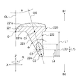
- Each of the plurality of electrode protrusions 22 has the cross-sectional shape of FIG. FIG. 3 shows a virtual straight line OE connecting the cross-sectional center C1 of the base end portion 23 and the cross-sectional center C2 of the tip end portion 24.
- the virtual straight line OE is also referred to as "electrode axis OE" for convenience.
- the virtual straight line OE corresponds to the central axis of the electrode projection 22 so to speak.
- arrows indicating the proximal end side B1 and the distal end side B2 of the electrode projection 22 are drawn.
- FIG. 3 illustrates some design parameters for explaining the shape of the electrode projection 22.
- the design parameters include an inclination angle ⁇ , a taper angle ⁇ , and dimensions L1, L2, and L3.
- the dimensions L1, L2, and L3 are the total height L1 of the electrode protrusion 22 with respect to the electrode forming surface 21b, the value L2 which is half of the dimension L1, and the height dimension L3 of the tip portion 24, respectively.
- the electrode axis OE and the main center axis OL form an inclination angle ⁇ .
- Each electrode protrusion 22 is also tilted so as to have an inclination angle ⁇ with respect to the main center axis OL.
- the tip portion 24 expands toward the outer diameter side with respect to the arrangement center point O.
- the electrode protrusion 22 has an oblique conical shape with rounded vertices.
- the surface on the inner diameter side that is, the surface closer to the main central axis OL is also referred to as an inner peripheral side surface 22i.
- the surface on the outer diameter side that is, the surface far from the main central axis OL is also referred to as the outer peripheral side surface 22e.
- the outer peripheral side surface 22e is not parallel to the main central axis OL and has a certain degree of inclination.
- the tilt angle of the outer peripheral side surface 22e with respect to the main central axis OL is smaller than the tilt angle ⁇ .
- the height dimension L3 of the tip portion 24 is smaller than the dimension L2. As a result, the ratio of the base end portion 23 to the electrode protrusions 22 can be increased, and the shape retention of the electrode protrusions 22 is enhanced.
- the interface 25 is parallel to the radial direction X and parallel to the electrode forming surface 21b.
- the interface 25 corresponds to a cross section cut at the boundary between the base end portion 23 and the tip end portion 24.
- the interface 25 intersects the electrode axis OE diagonally.
- the normal of the interface 25 and the electrode axis OE form an angle larger than zero degree.
- the taper angle ⁇ of the electrode protrusion 22 is arbitrarily set within a range of more than 0 degrees and less than 90 degrees.
- the base end portion 23 and the tip end portion 24 have the same taper angle ⁇ .
- the base end portion 23 and the tip end portion 24 are smoothly connected without a step at the interface 25.
- Each of the base end portion 23 and the tip end portion 24 is constructed of conductive rubber.
- the conductive rubber of the embodiment is specifically a conductive silicone rubber containing a silicone rubber and conductive particles.
- the silicone rubber may be, for example, a room temperature curable liquid silicone rubber.
- the room temperature curing type liquid silicone rubber is in the form of a liquid or a paste before curing, and the curing reaction proceeds at 20 ° C to 100 ° C to become a rubber elastic body.
- a reinforcing material, a filler, various additives and the like may be appropriately contained.
- the conductive particles may be, for example, metal particles.
- the metal particles may be, for example, silver particles.
- the silver particles may contain agglomerated particles (aggregates) in which a plurality of silver particles (primary particles) are agglomerated, may contain flake-shaped silver particles, or may contain both of them.
- the conductive particles may be other metal particles, conductive carbon-based material particles, or the like. Other metal particles may be copper particles, gold particles, aluminum particles, nickel particles and the like.
- the carbon-based material particles may be carbon black, graphite, carbon nanotubes, or the like.
- the carbon black may be Ketjen black or acetylene black.
- the conductive rubber at the base end portion 23 is harder than the conductive rubber at the tip end portion 24.
- the amount of the conductive particles at the base end portion 23 is larger than the amount of the conductive particles at the tip end portion 24.
- the material for constructing the tip portion 24 is also referred to as a "first material” for convenience, and the material for constructing the base end portion 23 is also referred to as a "second material” for convenience.
- the second material has a higher content of conductive particles than the first material.
- the first material for constructing the tip 24 may be as flexible as possible. However, in the first material, the total amount of the conductive particles may be three times or more the amount of the binder, whereby good conductivity may be ensured.
- the second material for constructing the base end portion 23 may be a material as hard as possible. However, in the second material, the total amount of the conductive particles may be 4 times or less the amount of the binder, whereby the fluidity may be ensured.
- the total amount (weight portion) of the conductive particles is described as "R 1" for convenience.
- the total amount of the conductive particles (parts by weight) for convenience as "R 2".
- the tips 24 of the plurality of electrode protrusions 22 are brought into contact with the measured portion.
- the measured site is, for example, the body (skin) of the subject.
- the biological signal of the subject is detected via the connector 30.
- the biological electrode 1 detects, for example, an electroencephalogram or a biological signal other than an electroencephalogram.
- the electrode member 20 is electrically connected to a measuring device (not shown) via the connector 30.
- the measuring device is not particularly limited, and may be, for example, an electroencephalogram measuring device, a wearable information device, or a health monitoring device.
- the soft tip portion 24 can reduce the burden on the measured portion, and the base end portion 23, which is harder than the tip portion 24, can easily maintain the electrode shape.
- the surface pressure may decrease due to permanent deformation (plastic deformation) or the like.
- the electrode protrusion 22 in its initial shape as much as possible.
- the base end portion 23 is harder than the tip portion 24, it is easy to maintain the electrode shape, while the softness of the tip portion 24 can suppress the burden on the measured portion.
- the difference in the hardness of the conductive rubber is created between the tip portion 24 and the base end portion 23 by differently blending the conductive particles.
- Increasing the amount of conductive particles has the advantage of improving the rigidity as well as the conductivity. Therefore, the embodiment also has an excellent feature that both rigidity and conductivity can be achieved at the same time.
- each electrode projection 22 is open to the outer diameter side with respect to the main central axis OL. As a result, when the biological electrode 1 is pressed against the measurement site, the electrode projection 22 can be elastically deformed and stably cover a wide range of the measurement area.
- the conductivity and rigidity of the base end portion 23 are ensured by the hard conductive rubber.
- the embodiment is also characterized in that the base end portion 23 is constructed only from the conductive rubber, and the metal insert component for reinforcement (for example, a metal rod or the like) is not provided inside the base end portion 23.
- the interface 25 diagonally intersects the electrode axis OE.
- the area of the interface 25 can be increased as compared with the case where they intersect vertically.
- FIGS. 4 and 10 are front views of the biological electrodes 101 and 201 of the first modified example and the second modified example, respectively.
- 5A, 11th, and 15th are vertical cross-sectional views of the electrode projections 122, 222, and 222 of the first modification to the third modification, respectively.
- 5 and 11 and 15 are vertical cross-sectional views obtained by cutting each of the bioelectrodes of the modified example on a virtual plane corresponding to the M1-M1 line of FIG. 2, similarly to the bioelectrode 1.
- FIGS. 5, 11 and 15, similarly to FIG. 3, the cross-sectional centers C1 and C2, the electrode axis OE, and the design parameters ⁇ , ⁇ , L1, L2, and L3 are entered.
- the first modification will be described with reference to FIGS. 4 to 9.
- 4 and 5 show the structure of the bioelectrode 101 of the first modification.
- the bioelectrode 101 has the same configuration as the bioelectrode 1 of the embodiment, except that the electrode member 20 is replaced with the electrode member 120.
- the electrode member 120 includes a supported portion 121 and a plurality of electrode protrusions 122 extending from the supported portion 121.
- the shape of the supported portion 121 may be the same as that of the supported portion 21.
- the supported portion 121 includes a supported surface 121a and an electrode forming surface 121b that are opposite to each other.
- Each electrode projection 122 includes a base end portion 123, a tip end portion 124, and a connection end face 125.
- the connection end surface 125 is an end surface of the base end portion 123 and is also a surface connected to the tip end portion 124.
- a protrusion 125a is provided at the center of the connection end surface 125.
- the bioelectrode 101 of the first modification has some characteristic configurations.
- One of the features is a "protrusion” and a “dent” provided at the interface between the base end portion 123 and the tip end portion 124. These "protrusions” and “dents” fit into each other.
- the base end portion 123 is provided with the protrusion 125a
- the tip portion 123 is provided with a “dent” for receiving the protrusion 125a.
- the tip portion 124 is covered with the protrusion portion 125a, and the protrusion portion 125a is buried inside the tip portion 124.
- the surface area in which the tip end portion 124 and the base end portion 123 are in contact with each other can be increased, so that the adhesive force is improved by increasing the contact area.
- the peripheral edge of the connection end face 125 forms an annular step.
- the annular step is constructed so that the tip portion 124 is slightly thinner than the base end portion 123. As a result, the tip portion 124 becomes easy to bend, and the burden on the measured portion is further reduced.
- the tip portion 124 is formed of the above-mentioned first material, and the base end portion 123 is formed of the above-mentioned second material.
- the base end portion 123 is molded with conductive silicone rubber, and this becomes an intermediate product.
- FIG. 6 is a bottom perspective view showing an intermediate product of the bioelectrode 101
- FIG. 7 is a front view thereof.
- the base end portion 123 after molding is set in the mold 150 (see FIG. 9) for forming the tip end portion.
- FIG. 8 is a bottom perspective view of the electrode member 120 of the biological electrode 101. Although the outer periphery of the supported portion 121 is schematically shown in FIGS. 6 and 8, the peripheral edge of the supported portion 121 can be cut slightly smaller.
- FIG. 9 is a cross-sectional view of the mold 150 for constructing the tip portion 124 of the bioelectrode 101.
- the annular step of the connecting end face 125 can regulate the position (depth) at which the intermediate product of FIGS. 6 and 7 is inserted when the tip portion 124 is formed. That is, the mold 150 has an oblique conical hole portion 152 according to the shape of the electrode projection 122.
- the oblique conical hole portion 152 is provided with a step corresponding to the annular step of the connection end face 125. This step facilitates the positioning (depth determination) of the intermediate product.
- the protrusion 125a may be provided, while the annular step of the connection end face 125 may be omitted.
- the omission of the annular step is realized by deforming the shape of the oblique conical hole portion provided in the mold 150.
- an oblique conical hole portion 152 for smoothly connecting the tip end portion 124 and the base end portion 123 so as to have the same taper angle is provided.
- a modification in which the protrusion 125a is omitted may be provided. In this case, the end face of the base end portion 123 becomes flat, and a slightly thinner tip portion 124 is connected to the flat end face.
- the protrusion 125a fits into the recess of the tip portion 124 at the interface between the base end portion 123 and the tip portion 124. As a result, the contact surface area can be secured, and the adhesive strength is improved.
- the peripheral edge of the connection end face 125 constructs an annular step. Due to the annular step, the tip portion 124 is constructed to be slightly thinner than the base end portion 123.
- the second modification will be described with reference to FIGS. 10 to 14.
- 10 and 11 show the structure of the bioelectrode 201 of the second modification.
- the bioelectrode 201 has the same configuration as the bioelectrode 1 of the embodiment, except that the electrode member 20 is replaced with the electrode member 220.
- the electrode member 220 includes a supported portion 221 and a plurality of electrode protrusions 222 extending from the supported portion 221.
- the shape of the supported portion 221 may be the same as that of the supported portion 21.
- the supported portion 221 includes a supported surface 221a and an electrode forming surface 221b that are opposite to each other.
- Each electrode projection 222 includes a base end portion 223 and a tip end portion 224.
- FIG. 11 also shows the cross-sectional center C3 in the central body portion of the tip portion 224.
- FIG. 12 is a diagram showing a manufacturing process of the bioelectrode 201.
- the tip portion 224 is preformed as an insert part.
- FIG. 13 is a front view showing an insert component of the second modification of the embodiment.
- the material of the tip portion 224 is the above-mentioned "first material”.
- the tip portion 224 has a front end 224a, a central body portion 224b, and a rear end 224c along the central axis OP.
- the central body portion 224b is bulged more than both ends.
- FIG. 12 shows a mold 250 used for manufacturing the electrode member 220.
- the mold 250 has a plurality of oblique conical holes 252.
- the tip portion 224 which is an insert component, is set in the oblique conical hole portion 252 as shown by an arrow in FIG.
- the above-mentioned "second material" is put into the mold 250, the base end portion 223 and the supported portion 221 are formed, and the electrode member 220 of the two-color molded product is obtained.
- FIG. 14 is a bottom perspective view showing the electrode member 220.
- the bioelectrode 201 of the second modification has some characteristic configurations.
- One of the features is a "protrusion” and a “dent” provided at the interface between the base end 223 and the tip 224, which fit together at the interface.
- the rear end 224c of the tip 224 forms a "protrusion”
- the base end 223 is provided with a "recess” for receiving the rear end 224c.
- exactly half of the tip portion 224 that is, up to the central body portion 224b
- the base end 223 can stably hold the tip 224 when the tip 224 receives a force.
- less than half or more than half of the tip 224 may be buried in the proximal 223.
- the tip portion 224 is used as an insert part. Insert parts provide manufacturing advantages.
- the tip portion 224 can be formed of any shape and material independently of the manufacturing conditions imposed on the resin molding process of the base end portion 223.
- tip 224 has the various "symmetries" described below.
- the "first symmetrical shape" of the tip portion 224 is a "mirror image symmetrical shape" when the cross section P1 of the central body portion shown in FIG. 13 is used as a mirror image plane.
- One of its advantages is the improvement of workability during manufacturing. For example, when the tip portion 224 is an insert component, the front end 224a and the rear end 224c may be reversed, which reduces the burden on the operator.
- the "second symmetrical shape" of the tip portion 224 is a rotationally symmetric shape when the central axis OP (see FIG. 13) in the length direction of the tip portion 224 is used as the rotation axis.
- This rotationally symmetric shape may be, for example, 1/2 rotational symmetry, 1/3 rotational symmetry, or n rotational symmetry.
- the tip portion 224 is used as an insert component, the workability when the tip portion 224 is arranged in the mold is improved.
- the joint surface between the tip portion 224 and the base end portion 223 is also rotationally symmetric, so that the joint strength tends to be uniform.
- the "third symmetrical shape" of the tip portion 224 is a symmetrical shape with both ends tapered, and more specifically, the cross section along the central axis OP is a rhombus.
- the front end 224a and the rear end 224c have the same taper angle ⁇ i .
- the replacement of the front end 224a and the rear end 224c is reversible, and the tip portion 224 becomes rotatable around its central axis. Therefore, there is no limitation on the setting direction in the mold 250, and workability is improved.
- the taper angle ⁇ i may be equal to the taper angle ⁇ of the base end portion 223.
- the magnitude relationship between the taper angle ⁇ i and the taper angle ⁇ may be ⁇ i ⁇ or ⁇ i > ⁇ .
- the tip portion 224 includes all the above-mentioned first to third symmetrical shapes. However, the tip portion 224 may be deformed so as to have any one or two symmetrical shapes among them.
- the tip portion 224 may be deformed into an asymmetrical shape.
- the tip portion 224 may be deformed into an arbitrary shape that is non-mirror image symmetric with respect to the central cross section P1.
- the side of the front end 224a may be an oblique cone
- the side of the rear end 224c may be a cylinder, a prism, a truncated cone or a truncated cone.
- the front end 224a and rear 224c Tonouchi one taper angle phi i may be larger than the other.
- a structure similar to that of the tip portion 224 may be created by a manufacturing method other than the use of insert parts.
- a "projection" may be provided at the bottom of the oblique conical hole portion 252 in the mold 250, and the base end portion 223 may be formed by the oblique conical hole portion 252 with the protrusion.
- a part of the tip portion 224 may be embedded on the side of the base end portion 223 by forming the tip portion 224 in this “recess that is recessed on the base end side”.
- the rear end 224c of the tip portion 224 fits into the recess of the base end portion 223.
- the contact surface area can be secured, and the adhesive strength is improved.
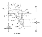
- the third modification will be described with reference to FIG. FIG. 15 is a vertical cross-sectional view of the electrode protrusion 322.
- the base end portion of the third modification has a double structure including a base end portion 323a (hereinafter, also referred to as an inner base end portion 323a) and a base end portion 323b (hereinafter, also referred to as an outer base end portion 323b).
- the inner base end portion 323a protrudes from the electrode forming surface 321b by a height L5.
- the outer base end portion 323b is covered with the inner base end portion 323a so as to bury the inner base end portion 323a.
- the outer base end portion 323b continuously extends in an oblique conical shape toward the tip end side B2, and the end thereof is the tip end portion 324.
- the inner base end portion 323a and the supported portion 321 are formed rigidly by the above-mentioned "second material”.
- the outer base end portion 323b and the tip end portion 324 are entirely softly formed of the above-mentioned "first material”.
- the protrusion portion is buried in the depression. (Refer to the cross-sectional view of each modification).
- the embodiment is not limited to such a shape.
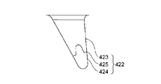
- FIG. 16 and 17 are front views of the electrode projection 422 of another modified example.
- the base end portion 423 having a concave recess and the tip portion 424 having a convex protrusion are fitted to each other. It may be constructed.
- the interface 425 appears on the outer surface of the electrode protrusion 422, and the uneven line of the interface 425 is visible from the outside.
- the "protrusion portion” may include a "high step portion”
- the "dent” may include a "low step portion”.
- a pair of steps may be provided in which the base end portion 423 and the tip end portion 424 fit into each other without a gap.
- the uneven line of the interface 425 appears on the outer surface of the electrode projection 422.
- modifications may be applied to the embodiments and the first to third modifications.
- One or a plurality of types of arbitrary modifications may be selected from the following variants, and the modifications may be applied to the embodiment and the first to third variants thereof.
- the design parameters ⁇ to L5 of the electrode projections 22 to 322 shown in FIGS. 3, 5, 11 and 15 can be changed in various ways.
- the tilt angle ⁇ can be transformed into any angle.
- the inclination angle ⁇ may be set so that the respective electrode projections 22 to 322 project vertically from the electrode forming surfaces 21b to 321b.
- the electrode axis OE of each electrode projection 22 is parallel to the main center axis OL and the axial direction Z.
- a shape that does not have a taper angle ⁇ may be used.
- One or both of the base end portions 23 to 323 and the tip end portions 24 to 324 may be constructed so as to have a uniform thickness without taper.
- the heights L3, L4, and L5 may have dimensions L2 or more.
- the tip portions 24 to 324 may be shorter than the base end portions 23 to 323, conversely may be longer, or they may have the same length.
- the thicknesses of the tip portions 24 to 324 and the base end portions 23 to 323 may be changed independently of each other.
- the tip portions 24 to 324 may be made thicker than the base end portions 23 to 323.
- the basic shape of the bioelectrode of the present disclosure is not limited to the embodiments and the bioelectrodes 1, 101, 201 of the modified examples thereof, and the features of the present disclosure can be applied to various bioelectrode shapes.
- the arrangement method of each of the plurality of electrode protrusions 22 to 322 can be arbitrarily modified. It is not limited to the circular shape as in the embodiment, and a comb-shaped (comb-shaped) lined up in a row and a plurality of electrode protrusions 22 to 322 may be arranged.
- the number of the electrode projections 22 to 322 may be any number, for example, one.
- the overall shape of the electrode protrusions 22 to 322 is not necessarily limited to the oblique conical shape, and may be, for example, a thin pin shape, a bent pin shape, or a plate shape, for example.
- FIG. 18 is a table showing the bioelectrode material components of the examples.
- material E1 is applied as an example of the above-mentioned first material
- material E2 is applied as an example of the above-mentioned second material.
- Each of Material E1 and Material E2 contains 100 parts by weight of the binder.
- the binder is a liquid silicone rubber, and as an example, the trade name "KE-106" manufactured by Shin-Etsu Chemical Co., Ltd. is used.
- the binder contains a curing agent.
- the curing agent used is the trade name "CAT-RG” manufactured by Shin-Etsu Chemical Co., Ltd.
- a total of 300 parts by weight of silver powder (that is, silver particles) is mixed with 100 parts by weight of the binder in the material E1.
- the silver powder of the material E1 is composed of 150 parts by weight of the first silver powder and 150 parts by weight of the second silver powder.
- the first silver powder has a trade name of "FA-2-3” and the second silver powder has a trade name of "G-35", both of which are manufactured by DOWA Electronics.
- Hydrophobic fumed silica manufactured by Nippon Aerosil Co., Ltd .: trade name "AEROSIL (registered trademark) R972" is mixed in advance with about 2 wt% of G-35 as a measure against agglutination.
- the material E2 a total of 400 parts by weight of silver powder (silver particles) is blended with respect to 100 parts by weight of the binder.
- the silver powder of the material E2 is composed of 200 parts by weight of the first silver powder and 200 parts by weight of the second silver powder.
- 20 parts by weight of each of the material E1 and the material E2 are mixed with the dispersant.
- 20 parts by weight of the dispersant comprises 10 parts by weight of the first dispersant and 10 parts by weight of the second dispersant.
- the first dispersant has a trade name of "KF-6015" and the second dispersant has a trade name of "KF-6106", both of which are manufactured by Shin-Etsu Chemical Co., Ltd.
- the connector 30 is attached to the support member 10 in advance.
- the conductive rubber containing the silicone rubber and the metal particles is agitated.
- the conductive rubber may be in the form of a liquid or a paste.
- the agitated conductive rubber is injected into a molding die (cavity) having a plurality of oblique conical holes.
- the base end portion 23 and the supported portion 21 are formed. That is, after the mold is cooled, the "material E2 (see FIG. 18)" is further charged into the oblique conical hole portion of the mold. Subsequently, the assembly of the support member 10 and the connector 30 is placed on the conductive rubber in the mold with the support surface 10a of the support member 10 facing downward. As a result, the support surface 10a of the support member 10 is placed so as to overlap the supported surface 21a.
- the electrode member 20 made of conductive silicone rubber can be obtained. After that, the electrode member 20 is immersed in a 10% NaCl aqueous solution, and is heated and pressurized at 121 ° C. and 0.1 MPa for 1 hour. An autoclave is used for heating and pressurizing.
- the conductive rubber molded into the shape of the electrode member 20 is crosslinked. As a result, the parts are integrated. After that, the integrated bioelectrode 1 is taken out from the molding die (that is, demolded).
- FIG. 19 is a graph showing the relationship between the amount of silver powder and the hardness of the biological electrode 1 of the example.
- the hardness in FIG. 19 is the shore A hardness.
- the shore A hardness is 51 when the blending amount of the silver powder is 150 parts by weight
- the amount of silver powder blended in the base end portion 23 may be larger than the amount of silver powder blended in the tip portion 24 so as to increase the hardness of Shore A by 1.2 times or more.
- the silver powder (that is, silver particles) is not limited as long as it can be dispersed in the silicone rubber that is the binder.
- agglutinating silver powder and flake-like silver powder may be used.
- the aggregated silver powder is a three-dimensional aggregate of a plurality of particulate primary particles, and the above-mentioned trade name "G-35" is exemplified.
- the flake-shaped silver powder has a scaly shape. Both agglutinating silver powder and flake-like silver powder may be blended.
- the amount of each of FA-2-3 and G35 in the material E1 may be 1.5 times or more the amount of the binder. In this case, the total amount of silver powder may be 3.0 times or more the amount of the binder.
- the amount of each of FA-2-3 and G35 in the material E2 may be 2.0 times or less the amount of the binder. In this case, the total amount of silver powder may be 4.0 times or less the amount of the binder.
- FA-2-3 and G35 are not limited to the same blending amount, and one may be larger than the other.
- the above embodiments include at least specific disclosures of material components, material trade names, hardness, and manufacturing methods.
- the specific disclosure of the above-mentioned examples may be applied to the bioelectrodes of the first to third modified examples or those obtained by further modifying them.
Landscapes
- Life Sciences & Earth Sciences (AREA)
- Health & Medical Sciences (AREA)
- Medical Informatics (AREA)
- Biophysics (AREA)
- Pathology (AREA)
- Engineering & Computer Science (AREA)
- Biomedical Technology (AREA)
- Heart & Thoracic Surgery (AREA)
- Physics & Mathematics (AREA)
- Molecular Biology (AREA)
- Surgery (AREA)
- Animal Behavior & Ethology (AREA)
- General Health & Medical Sciences (AREA)
- Public Health (AREA)
- Veterinary Medicine (AREA)
- Measurement And Recording Of Electrical Phenomena And Electrical Characteristics Of The Living Body (AREA)
Priority Applications (4)
| Application Number | Priority Date | Filing Date | Title |
|---|---|---|---|
| US17/924,000 US20230270364A1 (en) | 2020-07-03 | 2021-06-07 | Bioelectrode |
| CN202180036718.4A CN115666384A (zh) | 2020-07-03 | 2021-06-07 | 生物电极 |
| JP2022533774A JP7511642B2 (ja) | 2020-07-03 | 2021-06-07 | 生体電極 |
| EP21834471.1A EP4176810B1 (en) | 2020-07-03 | 2021-06-07 | Bioelectrode |
Applications Claiming Priority (2)
| Application Number | Priority Date | Filing Date | Title |
|---|---|---|---|
| JP2020115673 | 2020-07-03 | ||
| JP2020-115673 | 2020-07-03 |
Publications (1)
| Publication Number | Publication Date |
|---|---|
| WO2022004282A1 true WO2022004282A1 (ja) | 2022-01-06 |
Family
ID=79315282
Family Applications (1)
| Application Number | Title | Priority Date | Filing Date |
|---|---|---|---|
| PCT/JP2021/021544 Ceased WO2022004282A1 (ja) | 2020-07-03 | 2021-06-07 | 生体電極 |
Country Status (5)
| Country | Link |
|---|---|
| US (1) | US20230270364A1 (https=) |
| EP (1) | EP4176810B1 (https=) |
| JP (1) | JP7511642B2 (https=) |
| CN (1) | CN115666384A (https=) |
| WO (1) | WO2022004282A1 (https=) |
Cited By (1)
| Publication number | Priority date | Publication date | Assignee | Title |
|---|---|---|---|---|
| JPWO2024029446A1 (https=) * | 2022-08-04 | 2024-02-08 |
Citations (7)
| Publication number | Priority date | Publication date | Assignee | Title |
|---|---|---|---|---|
| JP2013111361A (ja) | 2011-11-30 | 2013-06-10 | Japan Health Science Foundation | 脳波測定用電極、脳波測定用部材、及び、脳波測定装置 |
| US20160143554A1 (en) * | 2014-11-20 | 2016-05-26 | Samsung Electronics Co., Ltd. | Apparatus for measuring bioelectrical signals |
| JP2017074369A (ja) | 2015-10-13 | 2017-04-20 | ニッタ株式会社 | 脳波測定用電極 |
| JP2018102964A (ja) * | 2015-01-14 | 2018-07-05 | 東洋紡株式会社 | 生体情報計測用衣類 |
| JP2018175288A (ja) | 2017-04-11 | 2018-11-15 | ニッタ株式会社 | 脳波測定用電極 |
| WO2020080396A1 (ja) * | 2018-10-17 | 2020-04-23 | Nok株式会社 | 生体電極及び生体電極の製造方法 |
| WO2020085034A1 (ja) * | 2018-10-26 | 2020-04-30 | 住友ベークライト株式会社 | 生体用電極、生体センサーおよび生体信号測定システム |
Family Cites Families (10)
| Publication number | Priority date | Publication date | Assignee | Title |
|---|---|---|---|---|
| JP3591560B2 (ja) * | 1996-09-17 | 2004-11-24 | 日本ゼオン株式会社 | ゴム組成物 |
| JP4947858B2 (ja) * | 2001-08-21 | 2012-06-06 | 東レ・ダウコーニング株式会社 | 導電性液状シリコーンゴム組成物、導電性シリコーンゴム成形物およびその製造方法 |
| JP3631210B2 (ja) * | 2002-02-07 | 2005-03-23 | 象印チエンブロック株式会社 | 鉄骨建方用パンチ治具 |
| KR200322161Y1 (ko) * | 2003-05-02 | 2003-08-06 | 김장범 | 조립식 방석 |
| KR200437863Y1 (ko) * | 2006-10-23 | 2008-01-02 | 정창선 | 조립식 난간 |
| US20100025100A1 (en) * | 2007-03-05 | 2010-02-04 | Shokichi Hamano | Electrically conductive polymeric elastomer composition and electromagnetic wave shield comprising the composition |
| WO2018186212A1 (ja) * | 2017-04-07 | 2018-10-11 | アルプス電気株式会社 | 生体情報測定用電極および生体情報の測定方法 |
| WO2019108968A1 (en) * | 2017-12-01 | 2019-06-06 | Zeto, Inc. | Headset and electrodes for sensing bioelectrical potential and methods of operation thereof |
| US11647953B2 (en) * | 2018-02-08 | 2023-05-16 | X Development Llc | Hair ratcheting electroencephalogram sensors |
| WO2021254601A1 (en) * | 2020-06-16 | 2021-12-23 | IDUN Technologies AG | Three-dimensional electrode arrangement |
-
2021
- 2021-06-07 EP EP21834471.1A patent/EP4176810B1/en active Active
- 2021-06-07 JP JP2022533774A patent/JP7511642B2/ja active Active
- 2021-06-07 WO PCT/JP2021/021544 patent/WO2022004282A1/ja not_active Ceased
- 2021-06-07 US US17/924,000 patent/US20230270364A1/en active Pending
- 2021-06-07 CN CN202180036718.4A patent/CN115666384A/zh active Pending
Patent Citations (7)
| Publication number | Priority date | Publication date | Assignee | Title |
|---|---|---|---|---|
| JP2013111361A (ja) | 2011-11-30 | 2013-06-10 | Japan Health Science Foundation | 脳波測定用電極、脳波測定用部材、及び、脳波測定装置 |
| US20160143554A1 (en) * | 2014-11-20 | 2016-05-26 | Samsung Electronics Co., Ltd. | Apparatus for measuring bioelectrical signals |
| JP2018102964A (ja) * | 2015-01-14 | 2018-07-05 | 東洋紡株式会社 | 生体情報計測用衣類 |
| JP2017074369A (ja) | 2015-10-13 | 2017-04-20 | ニッタ株式会社 | 脳波測定用電極 |
| JP2018175288A (ja) | 2017-04-11 | 2018-11-15 | ニッタ株式会社 | 脳波測定用電極 |
| WO2020080396A1 (ja) * | 2018-10-17 | 2020-04-23 | Nok株式会社 | 生体電極及び生体電極の製造方法 |
| WO2020085034A1 (ja) * | 2018-10-26 | 2020-04-30 | 住友ベークライト株式会社 | 生体用電極、生体センサーおよび生体信号測定システム |
Non-Patent Citations (1)
| Title |
|---|
| See also references of EP4176810A4 |
Cited By (3)
| Publication number | Priority date | Publication date | Assignee | Title |
|---|---|---|---|---|
| JPWO2024029446A1 (https=) * | 2022-08-04 | 2024-02-08 | ||
| WO2024029446A1 (ja) * | 2022-08-04 | 2024-02-08 | Nok株式会社 | 生体用電極 |
| JP7826491B2 (ja) | 2022-08-04 | 2026-03-09 | Nok株式会社 | 生体用電極 |
Also Published As
| Publication number | Publication date |
|---|---|
| EP4176810A1 (en) | 2023-05-10 |
| EP4176810A4 (en) | 2024-05-22 |
| CN115666384A (zh) | 2023-01-31 |
| EP4176810C0 (en) | 2025-01-01 |
| JPWO2022004282A1 (https=) | 2022-01-06 |
| US20230270364A1 (en) | 2023-08-31 |
| JP7511642B2 (ja) | 2024-07-05 |
| EP4176810B1 (en) | 2025-01-01 |
Similar Documents
| Publication | Publication Date | Title |
|---|---|---|
| WO2022004282A1 (ja) | 生体電極 | |
| WO2018230445A1 (ja) | 生体電極 | |
| CN104736048B (zh) | 生物医学电极 | |
| EP4282464B1 (en) | Electrode helmet for electrical recording and/or stimulation | |
| JP6927632B2 (ja) | 脳波測定用電極 | |
| JP7395624B2 (ja) | 生体電極 | |
| CN112672714A (zh) | 植体构造物 | |
| JP2021159216A (ja) | 生体電気信号測定電極 | |
| EP4566538A1 (en) | Bioelectrode | |
| EP4295770B1 (en) | Bioelectrode | |
| JP2024159930A (ja) | アクチュエータ | |
| WO2020230652A1 (ja) | 電池の封止構造 | |
| JP7794007B2 (ja) | 生体電位電極体および生体電位センサ | |
| US20250214111A1 (en) | Rotor and ultrasonic motor | |
| WO2020230653A1 (ja) | 電池の封止構造 | |
| CN223245941U (zh) | 一种用于电子设备pin针固定保护的新型盖扣结构 | |
| CN221786745U (zh) | 一种刷头组件及电动牙刷 | |
| CN216015754U (zh) | 一种新型插针组件 | |
| JP7641456B2 (ja) | 金属粉末射出成形による眼鏡の鼻パッド支持部材の製造方法 | |
| JP2024179750A (ja) | 生体電極 | |
| WO2019115373A1 (en) | Sensor device for detecting an electrical signal | |
| JPWO2020121777A1 (ja) | 生体電極及び生体電極の製造方法 | |
| JPH0211047Y2 (https=) | ||
| JPS5884263A (ja) | ピストン装置 | |
| CN113768522A (zh) | 一种脑电信号传感器 |
Legal Events
| Date | Code | Title | Description |
|---|---|---|---|
| 121 | Ep: the epo has been informed by wipo that ep was designated in this application |
Ref document number: 21834471 Country of ref document: EP Kind code of ref document: A1 |
|
| ENP | Entry into the national phase |
Ref document number: 2022533774 Country of ref document: JP Kind code of ref document: A |
|
| WWE | Wipo information: entry into national phase |
Ref document number: 2021834471 Country of ref document: EP |
|
| NENP | Non-entry into the national phase |
Ref country code: DE |