WO2022004274A1 - コンピュータシステム及び制御装置 - Google Patents
コンピュータシステム及び制御装置 Download PDFInfo
- Publication number
- WO2022004274A1 WO2022004274A1 PCT/JP2021/021357 JP2021021357W WO2022004274A1 WO 2022004274 A1 WO2022004274 A1 WO 2022004274A1 JP 2021021357 W JP2021021357 W JP 2021021357W WO 2022004274 A1 WO2022004274 A1 WO 2022004274A1
- Authority
- WO
- WIPO (PCT)
- Prior art keywords
- unit
- arithmetic
- calculation
- arithmetic unit
- specific
- Prior art date
- Legal status (The legal status is an assumption and is not a legal conclusion. Google has not performed a legal analysis and makes no representation as to the accuracy of the status listed.)
- Ceased
Links
Images






Classifications
-
- G—PHYSICS
- G06—COMPUTING OR CALCULATING; COUNTING
- G06N—COMPUTING ARRANGEMENTS BASED ON SPECIFIC COMPUTATIONAL MODELS
- G06N10/00—Quantum computing, i.e. information processing based on quantum-mechanical phenomena
-
- G—PHYSICS
- G06—COMPUTING OR CALCULATING; COUNTING
- G06N—COMPUTING ARRANGEMENTS BASED ON SPECIFIC COMPUTATIONAL MODELS
- G06N10/00—Quantum computing, i.e. information processing based on quantum-mechanical phenomena
- G06N10/40—Physical realisations or architectures of quantum processors or components for manipulating qubits, e.g. qubit coupling or qubit control
-
- G—PHYSICS
- G06—COMPUTING OR CALCULATING; COUNTING
- G06F—ELECTRIC DIGITAL DATA PROCESSING
- G06F7/00—Methods or arrangements for processing data by operating upon the order or content of the data handled
- G06F7/38—Methods or arrangements for performing computations using exclusively denominational number representation, e.g. using binary, ternary, decimal representation
- G06F7/48—Methods or arrangements for performing computations using exclusively denominational number representation, e.g. using binary, ternary, decimal representation using non-contact-making devices, e.g. tube, solid state device; using unspecified devices
- G06F7/57—Arithmetic logic units [ALU], i.e. arrangements or devices for performing two or more of the operations covered by groups G06F7/483 – G06F7/556 or for performing logical operations
Definitions
- the present invention relates to a computer system and a control device.
- Patent Document 1 describes a quantum computer using a superconducting element.
- Quantum computers require a circuit configuration according to the calculation content. Therefore, in the conventional quantum computer, when the calculation content changes, it is necessary to reconfigure the circuit configuration of the quantum computer according to the calculation content. As a result, it is presumed that the user was burdened.
- an object of the present invention is to provide a computer system and a control device capable of reducing the need for reconstruction according to the operation content in the circuit configuration of a quantum computer.
- the computer system includes an acquisition unit for acquiring calculation contents, a calculation unit group including a plurality of calculation units for executing a calculation using a quantum effect or a thermal effect in a superconducting state, and a calculation. It includes a selection unit that selects a calculation unit from a group of calculation units based on the contents, and an execution unit that causes the calculation unit selected by the selection unit to execute a calculation.
- a calculation unit according to the calculation content is selected, and the calculation is executed by the calculation unit. Therefore, the need for reconfiguration according to the calculation content in the circuit configuration of the quantum computer is reduced.
- the arithmetic unit group includes a general-purpose arithmetic unit which is a general-purpose arithmetic unit and a specific arithmetic unit which is an arithmetic unit for a specific use, and in the selection unit, the arithmetic unit group matches the arithmetic content. If the specific arithmetic unit for the purpose is not included, the general-purpose arithmetic unit may be selected, and if the arithmetic unit group includes the specific arithmetic unit for the application that matches the arithmetic content, the specific arithmetic unit may be selected. ..
- a more appropriate calculation unit is selected according to the calculation content.
- the arithmetic unit group includes a plurality of specific arithmetic units for different uses, and the selection unit may select a specific arithmetic unit for the purpose that matches the arithmetic content.
- a more appropriate calculation unit is selected according to the calculation content.
- the arithmetic unit group may include a plurality of arithmetic units formed on the same substrate.
- the design may be easier than in the case where a plurality of arithmetic units are formed on different substrates.
- the arithmetic unit group may include a plurality of arithmetic units formed on different substrates.
- the arithmetic unit it is possible to arrange the arithmetic unit at a position suitable for each of the plurality of arithmetic units.
- the plurality of arithmetic units formed on the substrates different from each other include the plurality of arithmetic units formed on the substrates having different temperatures, and the plurality of arithmetic units formed on the substrates having different temperatures from each other.
- Each of the arithmetic units may be formed on a substrate having a temperature suitable for arithmetic by each arithmetic unit.
- the space inside the refrigerator can be used more efficiently.
- the selection unit may select a plurality of calculation units from the calculation unit group, and the execution unit may cause each of the plurality of calculation units selected by the selection unit to execute the calculation.
- the execution unit causes each of the plurality of arithmetic units selected by the selection unit to execute the arithmetic so that the arithmetic executed by each of the plurality of arithmetic units selected by the selection unit becomes asynchronous. May be good.
- the execution unit may cause each of the plurality of arithmetic units selected by the selection unit to execute the operation so that the operations executed by each of the plurality of arithmetic units selected by the selection unit are synchronized. good.
- the control device includes an acquisition unit for acquiring calculation contents and a plurality of calculation units for executing calculations using a quantum effect or a thermal effect in a superconducting state based on the calculation contents. It is provided with a selection unit for selecting an arithmetic unit from the included arithmetic unit group.
- a calculation unit according to the calculation content is selected, and the calculation is executed by the calculation unit. Therefore, the need for reconfiguration according to the calculation content in the circuit configuration of the quantum computer is reduced.
- the arithmetic unit group includes a general-purpose arithmetic unit which is a general-purpose arithmetic unit and a specific arithmetic unit which is an arithmetic unit for a specific use, and in the selection unit, the arithmetic unit group matches the arithmetic content. If the specific arithmetic unit for the purpose is not included, the general-purpose arithmetic unit may be selected, and if the arithmetic unit group includes the specific arithmetic unit for the application that matches the arithmetic content, the general-purpose arithmetic unit may be selected. ..
- a more appropriate calculation unit is selected according to the calculation content.
- the arithmetic unit group includes a plurality of specific arithmetic units for different uses, and the selection unit may select a specific arithmetic unit for the purpose that matches the arithmetic content.
- a more appropriate calculation unit is selected according to the calculation content.
- FIG. 1 It is a schematic block diagram of the computer system which concerns on one Embodiment of this disclosure. It is a figure which shows an example of the hardware composition of the control device which concerns on the same embodiment. It is a schematic block diagram of the measuring apparatus and the refrigerator which concerns on the same embodiment. It is a schematic block diagram of the general-purpose arithmetic unit which concerns on the same embodiment. It is a flowchart which shows the flow of the process by the computer system which concerns on the same embodiment. It is a figure which shows the result of having a NOR unit execute a NOR operation in Example 1. FIG. It is a figure for demonstrating the operation content of the multiplier unit in Example 1. FIG. It is a figure which shows the result of having a multiplier unit perform multiplication in Example 1. FIG.
- FIG. 2 It is a figure which shows the current flowing through three circuits in the simulation in Example 2.
- FIG. It is a figure which shows the current which flows in the loop of three qubits in the simulation in Example 2.
- FIG. It is a figure which shows the result of having performed the simulation which reproduces the operation of the operation unit in Example 2.
- FIG. 1 is a schematic configuration diagram of a computer system 1 according to an embodiment of the present disclosure.
- the computer system 1 mainly includes a control device 10, a measuring device 20, and a refrigerator 30.
- the control device 10 and the measuring device 20 are communicably connected via the communication network 15. Further, the measuring device 20 is connected to a plurality of arithmetic units arranged in the refrigerator 30.
- the communication network 15 can take various modes.
- the communication network 15 may be, for example, a data transmission network (WAN) or a local area network (LAN) connected to each other through a dedicated line.
- the communication network 15 will be described as being the Internet, which is a representative of a public network.
- the control device 10 and the measuring device 20 may be connected by a USB (Universal Serial Bus) cable, a GPIB (General Purpose Interface Bus) cable, or the like.
- USB Universal Serial Bus
- GPIB General Purpose Interface Bus
- the refrigerator 30 is provided with a group of arithmetic units including a plurality of arithmetic units for executing arithmetic operations using quantum effects or thermal effects in a superconducting state.
- a group of arithmetic units constitutes a quantum computer.
- the control device 10 can select a calculation unit for executing the calculation from the calculation unit group arranged in the refrigerator 30.
- the measuring device 20 causes a calculation unit selected by the control device 10 to perform various calculations.
- the configurations of the control device 10, the measuring device 20, and the refrigerator 30 will be described in detail.
- the control device 10 can select a calculation unit based on the calculation content and instruct the measuring device 20 to execute the calculation by the selected calculation unit.
- the control device 10 includes a storage unit 100, a display unit 105, an input unit 110, a processing unit 120, and a communication unit 130.
- the storage unit 100 stores various types of information.
- the storage unit 100 stores, for example, information for selecting an arithmetic unit.
- the storage unit 100 may store a table in which the arithmetic unit and the use of the arithmetic unit (for example, use such as factorization and protein structure analysis) are associated with each other.
- the table stores information indicating a plurality of arithmetic units and information indicating the usage associated with each arithmetic unit.
- Various information stored in the storage unit 100 is referred to by the processing unit 120 as necessary.
- the display unit 105 can display various screens.
- the display unit 105 can display a screen for specifying the calculation content.
- the display unit 105 displays various calculation contents and displays a screen on which the user can specify the calculation contents in various formats such as a check box type, a scroll type, and a pull-down type.
- the input unit 110 accepts input of various information according to the user's operation. For example, the input unit 110 receives the calculation content according to the user's operation. At this time, the input unit 110 may accept a plurality of calculation contents. Various information received by the input unit 110 is transmitted to the processing unit 120.
- the processing unit 120 executes various processes. Specifically, the processing unit 120 can select a calculation unit from the calculation unit group and instruct the measuring device 20 to execute the calculation on the selected calculation unit.
- the processing unit 120 includes an acquisition unit 122, a selection unit 124, an instruction unit 126, and a display control unit 128.
- the acquisition unit 122 can acquire various types of information. Specifically, the acquisition unit 122 can acquire various types of information from the storage unit 100, and can acquire various types of information received by the input unit 110. For example, the acquisition unit 122 can acquire the calculation content from the input unit 110 based on the user's operation. At this time, the acquisition unit 122 may acquire a plurality of calculation contents.
- the selection unit 124 can select a calculation unit from the calculation unit group arranged in the refrigerator 30 based on the calculation content acquired by the acquisition unit 122. Specifically, the selection unit 124 refers to the table stored in the storage unit 100 and selects a calculation unit according to the acquired calculation content.
- the arithmetic unit group includes a general-purpose arithmetic unit which is a general-purpose arithmetic unit and a specific arithmetic unit which is an arithmetic unit for a specific use. The selection unit 124 selects at least one of a general-purpose calculation unit and a specific calculation unit according to the calculation content.
- the selection unit 124 selects the general-purpose arithmetic unit.
- the selection unit 124 selects the specific arithmetic unit.
- the selection unit 124 can select a plurality of arithmetic units from the arithmetic unit group.
- the selection unit 124 may select a plurality of specific arithmetic units, or may select a general-purpose arithmetic unit and at least one specific arithmetic unit.
- the selection unit 124 can select a calculation unit for an application that matches each calculation content based on a plurality of calculation contents.
- the selection unit 124 may select a plurality of calculation units that match the calculation content based on one calculation content. That is, the calculation corresponding to one calculation content may be shared by a plurality of calculation units.
- the instruction unit 126 can instruct the execution of the calculation by the calculation unit. Specifically, the instruction unit 126 can transmit various signals to the measuring device 20 via the communication unit 130 and instruct the execution of the calculation by the calculation unit. In the present embodiment, the instruction unit 126 instructs the execution of the operation by the operation unit selected by the selection unit 124. Further, the instruction unit 126 may instruct the calculation unit to execute the calculation based on, for example, the user's operation.
- the instruction unit 126 can instruct the execution of the operation by the plurality of operation units.
- the instruction unit 126 can give an instruction regarding synchronization of operations by a plurality of operation units.
- the instruction unit 126 may instruct the timing of calculation by each of the plurality of calculation units based on the user's operation.
- the display control unit 128 controls the display of the display unit 105. Specifically, the display control unit 128 generates data on the screen displayed by the display unit 105, and transmits the generated data to the display unit 105. For example, the display control unit 128 can generate various screen data for the user to input the calculation content and transmit the generated data to the display unit 105.
- the communication unit 130 can send and receive various information.
- the communication unit 130 can transmit an instruction from the instruction unit 126 to the measuring device 20 via the communication network 15.
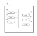
- FIG. 2 is a diagram showing an example of the hardware configuration of the control device 10 according to the present embodiment.
- the control device 10 includes a CPU (Central Processing Unit) 10a corresponding to the processing unit 120, a RAM (RandomAccessMemory) 10b corresponding to the storage unit 100, and a ROM (ReadOnlyMemory) 10c corresponding to the storage unit 100. It has a communication unit 10d, an input unit 10e, and a display unit 10f. Each of these configurations is connected to each other via a bus so that data can be transmitted and received.
- the control device 10 is composed of one computer will be described, but the control device 10 may be realized by combining a plurality of computers.
- the configuration shown in FIG. 2 is an example, and the control device 10 may have configurations other than these, or may not have a part of these configurations.
- the CPU 10a is a processing unit that controls execution of a program stored in the RAM 10b or the ROM 10c, calculates data, and processes the data.
- the CPU 10a is a processing unit that acquires calculation contents, selects a calculation unit, and executes a program (calculation instruction program) for instructing execution of the calculation.
- the CPU 10a receives various data from the input unit 10e and the communication unit 10d, displays the calculation result of the data on the display unit 10f, and stores the data in the RAM 10b.
- the RAM 10b is a storage unit in which data can be rewritten, and may be composed of, for example, a semiconductor storage element.
- the RAM 10b may store data such as a program executed by the CPU 10a, an operation result, and data necessary for the operation. It should be noted that these are examples, and data other than these may be stored in the RAM 10b, or a part of these may not be stored.
- the ROM 10c is a storage unit capable of reading data, and may be composed of, for example, a semiconductor storage element.
- the ROM 10c may store, for example, a calculation instruction program or data that is not rewritten.
- the communication unit 10d is an interface for connecting the control device 10 to another device.
- the communication unit 10d may be connected to a communication network such as the Internet.
- the input unit 10e receives data input from the user, and may include, for example, a keyboard and a touch panel.
- the display unit 10f is to be displayed on various screens, and may be configured by, for example, an LCD (Liquid Crystal Display).
- the display unit 10f may display, for example, a screen for inputting calculation contents.
- the calculation instruction program may be stored in a storage medium readable by a computer such as RAM 10b or ROM 10c and provided, or may be provided via a communication network connected by the communication unit 10d.
- the CPU 10a executes the calculation instruction program to realize various operations described with reference to FIG. 1. It should be noted that these physical configurations are examples and do not necessarily have to be independent configurations.
- the control device 10 may include an LSI (Large-Scale Integration) in which the CPU 10a and the RAM 10b and the ROM 10c are integrated.
- FIG. 3 is a schematic configuration diagram of the measuring device 20 and the refrigerator 30 according to the present embodiment.
- the measuring device 20 causes the calculation unit to execute various calculations.
- the measuring device 20 can cause various calculation units arranged in the refrigerator 30 to execute the calculation based on the instruction by the instruction unit 126 of the control device 10. More specifically, the measuring device 20 causes the arithmetic unit selected by the selection unit 124 to execute the arithmetic.
- the measuring device 20 includes a communication unit 200, a control unit 210, a first switch 220, and a second switch 222.
- the first switch 220 and the second switch 222 may exist as an actual structure, but are shown for convenience in order to improve the ease of understanding the state selected by the selection unit 124. Is also good. That is, the first switch 220 and the second switch 222 do not have to exist as an actual structure.
- the communication unit 200 is an interface for connecting the measuring device 20 to another device.
- the communication unit 200 is connected to the communication network 15.
- the communication unit 200 can transmit and receive various types of information.
- the communication unit 200 receives an instruction or the like from the control device 10.
- the control unit 210 executes various controls.
- the control unit 210 may include, for example, a microcomputer including a ROM, a RAM, a CPU, and the like.
- the control unit 210 includes an execution unit 212 and a switch control unit 214.
- the switch control unit 214 may exist as an actual structure, but may be shown for convenience in order to improve the ease of understanding the state selected by the selection unit 124.
- the general-purpose arithmetic unit 312, the specific arithmetic unit 318, and the execution unit 212 are electric, such as phosphor bronze wire, low resistance wire made of Cu or NbTi / CuNi, high-frequency wiring made of SCNi-CuNi, etc., or coaxial cable. It is connected by wiring to propagate the signal.
- the switch control unit 214 is shown for convenience as a device for controlling the connection between these two arithmetic units and the execution unit 212, it may exist as an actual structure.
- Execution unit 212 causes the calculation unit to execute the calculation. Specifically, the execution unit 212 transmits various signals to the calculation unit based on the instruction of the control device 10, and causes the calculation unit to execute the calculation.
- the execution unit 212 includes a signal generator.
- the signal generator is a device that generates various signals, and includes, for example, various devices such as an AWG (Arbitrary Waveform Generator), an oscillator, and a DC power supply. Further, the execution unit 212 may be arranged inside the refrigerator 30.
- the execution unit 212 can cause each arithmetic unit to execute the arithmetic so that the arithmetic executed by each of the plurality of arithmetic units selected by the selection unit 124 is synchronized. Specifically, the execution unit 212 can manage the timing of calculation by a plurality of calculation units by adjusting the timing of inputting signals to each calculation unit. For example, the execution unit 212 may cause a plurality of arithmetic units to start arithmetic at the same timing.
- the execution unit 212 can make each arithmetic unit execute an arithmetic so that the arithmetic executed by each of the plurality of arithmetic units selected by the selection unit 124 is asynchronous.
- the execution unit 212 may cause a plurality of arithmetic units to start arithmetic at different timings.
- the switch control unit 214 controls the states of the first switch 220 and the second switch 222, which are composed of various known switching elements, based on the instruction of the control device 10. Specifically, the switch control unit 214 controls the switch connected to the calculation unit that executes the calculation to the conduction state, and controls the switch connected to the calculation unit that does not execute the calculation to the open state. For example, when the arithmetic unit connected to the first switch 220 executes the calculation and the arithmetic unit connected to the second switch 222 does not execute the calculation, the switch control unit 214 makes the first switch 220 conductive. To control the second switch 222 to the open state.
- the first switch 220, the second switch 222, and the switch control unit 214 may exist as an actual structure, but are shown for convenience in order to improve the ease of understanding the state selected by the selection unit 124. It may be a thing. That is, the first switch 220, the second switch 222, and the switch control unit 214 do not have to exist as an actual structure.
- the refrigerator 30 is a refrigerator capable of realizing an extremely low temperature, and may be, for example, a refrigerator using a 3 He-4 He dilution refrigeration method. Internal temperature of the refrigerator 30 (more precisely, a 4.2K a boiling point of 4 He liquid at atmospheric pressure reduction) 4K may be temperature following. Further, the refrigerator 30 includes a substrate 310 that is adjusted to a predetermined temperature. In the present embodiment, the temperature of the substrate 310 is a temperature of several mK to several tens of mK. The temperature of the substrate 310 is not limited to this, and may be, for example, about 4.2 K or about 1 K.
- the arithmetic unit group includes a plurality of arithmetic units formed on the same substrate 310.
- the arithmetic unit contains a superconducting material and performs an arithmetic using a quantum effect or a thermal effect in a superconducting state. More specifically, the arithmetic unit can execute an arithmetic using quantum annealing or the like when the temperature of the arithmetic unit is equal to or lower than the superconducting transition temperature of the superconducting material.
- a reading circuit is connected to the calculation unit, and the calculation result and the like are read out as appropriate.
- the readout circuit is formed on the substrate 310, for example.
- the arithmetic unit is not limited to quantum annealing, and uses at least one of, for example, an ion trap, a coherent izing machine, a quantum gate element, a quantum dot, an NV (nitrogen vacancy) center, and a topological insulator (majorana fermion). You may.
- a general-purpose arithmetic unit 312, which is a general-purpose arithmetic unit, and a specific arithmetic unit 318, which is an arithmetic unit for a specific use, are formed on the substrate 310. That is, in the present embodiment, the arithmetic unit group includes a general-purpose arithmetic unit and a specific arithmetic unit.
- the arithmetic unit group includes a general-purpose arithmetic unit and a specific arithmetic unit.
- Each of the general-purpose arithmetic unit 312 and the specific arithmetic unit 318 is electrically connected to the measuring device 20. Specifically, each of the general-purpose arithmetic unit 312 and the specific arithmetic unit 318 is connected to the first switch 220 and the second switch 222 of the measuring device 20 through a coaxial cable or a twisted pair cable.
- the first switch 220 and the second switch 222 are shown for convenience, and are for propagating electric signals such as a coaxial cable or a twisted pair cable connected to each of the general-purpose arithmetic unit 312 and the specific arithmetic unit 318. Wiring may be directly connected to the measuring device 20.
- the general-purpose arithmetic unit 312 may be, for example, a circuit provided with a quantum gate element or the like.
- a plurality of substrates may be laminated or a plurality of substrates may be laminated.
- various configurations such as a configuration using an interposer or a TSV (Through Silicon Via) and a bump can be realized.
- the specific arithmetic unit 318 may have a circuit configuration suitable for a specific application.
- the specific arithmetic unit 318 may have a circuit configuration suitable for implementing a Hamiltonian form corresponding to the problem to be solved.
- the circuit configuration included in the specific arithmetic unit 318 may include, for example, a plurality of grids composed of qubits (for example, a grid as shown in FIG. 4).
- a fixed coupling may be used for the coupling between the plurality of qubits constituting the specific arithmetic unit 318 and the coupling between the lattices. That is, the coupling between the plurality of qubits constituting the specific arithmetic unit 318 and the coupling between the lattices may be fixed and may be immutable.
- the specific operation unit 318 is used for various purposes such as logical operation (for example, NOR operation, NAND operation, OR operation, AND operation, etc.), multiplication, factorization, protein structure analysis, knapsack optimization problem, portfolio optimization problem, and the like. It may be used for.
- logical operation for example, NOR operation, NAND operation, OR operation, AND operation, etc.
- multiplication for example, multiplication, factorization, protein structure analysis, knapsack optimization problem, portfolio optimization problem, and the like. It may be used for.
- FIG. 4 is a schematic configuration diagram of the general-purpose arithmetic unit 312 according to the present embodiment.
- the general-purpose arithmetic unit 312 according to the present embodiment includes a chimera graph composed of four grids (first grid 313, second grid 314, third grid 315, and fourth grid 316). Each lattice has a structure in which four qubits are arranged vertically and horizontally. Although four grids are shown in FIG. 4, the number of grids included in the general-purpose arithmetic unit 312 may be three or less, or may be five or more.
- each grid comprises four horizontally extending first qubits 301, four vertically extending second qubits 302, and 16 variable couplers 303. ..
- the variable coupler 303 couples one first qubit 301 and one second qubit 302, and the coupling can be adjusted as appropriate.
- the first qubit 301 and the second qubit 302 interact with each other according to the coupling by the variable coupler 303.
- each of the four first qubits 301 included in each lattice functions as separate qubits.
- Each first qubit 301 is connected to another qubit by a variable coupler and has an interaction with the other qubit.
- each of the four second qubits 302 included in each lattice functions as separate qubits.
- Each second qubit 302 is connected to another qubit by a variable coupler and has an interaction with the other qubit.
- each qubit can be connected to the end of the facing qubit contained in another lattice.
- the end 305 of the leftmost second qubit 302 included in the first grid 313 may be joined to the end 306 of the leftmost second qubit contained in the third grid 315.
- the number of grids used is appropriately adjusted according to the operation content. For example, if the operation content is a content that requires three qubits, one grid is used. Further, when the operation content is a content that requires seven qubits, for example, four lattices are used.
- the general-purpose arithmetic unit 312 executes an operation using a chimera graph.
- a Hamiltonian according to the problem to be solved is set by the user, and the Hamiltonian is mapped to the chimera graph.
- three qubits are required, so one grid is used. Will be.
- ⁇ i is the spin of the site i
- h i is the magnetic field of the site i
- J ij is the interaction between the spins of the site i and the site j
- n is the total number of sites.
- the general-purpose arithmetic unit 312 may include one or a plurality (for example, three) LUTs (LookUpTables), and may include a configuration capable of executing a desired arithmetic.
- LUTs LookUpTables
- the general-purpose arithmetic unit 312 includes a plurality of LUTs, at least two LUTs among the plurality of LUTs may be connected to each other.
- the selection unit 124 a screen for designating the calculation content is displayed on the display unit 105, and a mode in which the calculation content is designed by the user may be selected.
- the instruction unit 126 instructs the general-purpose calculation unit 312 to execute the calculation, and the general-purpose calculation unit 312 performs the calculation. It will be executed.
- FIG. 5 is a flowchart showing the flow of processing by the computer system 1 according to the present embodiment.
- the input unit 110 accepts the input of the calculation content based on the user's operation (step S101).
- the acquisition unit 122 acquires the calculation content received in step S101 (step S103).
- the selection unit 124 determines whether or not there is a specific calculation unit for the purpose that matches the calculation content acquired in step S103 (step S105). If the selection unit 124 determines that there is no specific calculation unit for the purpose that matches the calculation content (step S105: NO), the process proceeds to step S107. On the other hand, if the selection unit 124 determines that there is a specific calculation unit for the purpose that matches the calculation content (step S105: YES), the process proceeds to step S109.
- step S105 the selection unit 124 selects a general-purpose arithmetic unit from the arithmetic unit group (step S107). On the other hand, if YES is determined in step S105, the selection unit 124 selects a specific calculation unit for the purpose matching the calculation content from the calculation unit group (step S109).
- the instruction unit 126 When the selection unit 124 selects the calculation unit in step S107 or step S109, the instruction unit 126 generates an instruction to execute the calculation by the selected calculation unit (step S111).
- the communication unit 130 transmits an instruction to execute the calculation by the selected calculation unit to the measuring device 20 via the communication network 15 (step S113).
- the communication unit 200 of the measuring device 20 receives the instruction, and the execution unit 212 causes the selected arithmetic unit to execute the arithmetic based on the received instruction (step S115).
- the calculation unit arranged in the refrigerator 30 the calculation according to the calculation content is executed.
- the calculation result is observed by a measuring device (not shown) responsible for state observation (state reading) of the measuring device 20, and is transmitted to the control device 10 via the communication network 15. May be sent. Further, the calculation result may be displayed on the display unit 105 or stored in the storage unit 100.
- Example 1 In Example 1, two arithmetic units were arranged in the refrigerator 30 and an experiment was conducted.
- the two arithmetic units are an arithmetic unit that executes a NOR operation (hereinafter, also referred to as a “NOR unit”) and an arithmetic unit that executes multiplication (hereinafter, also referred to as a “multiplier unit”). ..
- NOR unit NOR operation
- multiplier unit arithmetic unit that executes multiplication
- each of the NOR unit and the multiplier unit is cooled to 10 mK in the refrigerator 30, and each of the NOR unit and the multiplier unit is made to perform the calculation in the superconducting state.
- the software "LabVIEW (registered trademark)" installed in the control device 10 is used for selecting the arithmetic unit (selecting the NOR unit or the multiplier unit) and instructing the arithmetic unit to execute the arithmetic. ..
- FIG. 6 is a diagram showing the result of having the NOR unit execute the NOR operation in the first embodiment.
- the NOR unit is made to execute the NOR operations of the inputs (0,0), (0,1), (1,0) and (1,1) 1000 times each.
- FIG. 6 shows a graph of four calculation results, and the calculation results of input (0,0), (0,1), (1,0) and (1,1) are shown in order from the top. ing.
- X and Y indicate an input (X, Y), and S indicates an operation result.
- the horizontal axis of the graph indicates (X, Y, S), and the vertical axis indicates the number of counts of the calculation result.
- the correct operation result is counted most. Therefore, in this embodiment, it can be said that the calculation is appropriately executed in the NOR unit.
- FIG. 7 is a diagram for explaining the calculation content of the multiplier unit in the first embodiment.
- Each of X, Y, Z and D shown in FIG. 7 corresponds to the input of the multiplier unit.
- C and S correspond to the calculation result of the multiplier unit.
- the circuit shown in FIG. 7 is a model of the relationship between the input and the output of the multiplier unit, and each of X, Y, Z, D, C and S is realized by qubits (Q1 to Q6). Will be done.
- FIG. 8 is a diagram showing the result of having the multiplier unit execute multiplication in the first embodiment.
- FIG. 8 shows the calculation results (C, S) for the inputs (X, Y, Z, D).
- the multiplier unit is made to perform multiplication with (0,0,0,0) to (1,1,1,1) as inputs. As shown in FIG. 8, it can be seen that an appropriate calculation result is obtained in any of the calculations.
- an arithmetic unit corresponding to the arithmetic content is selected from the arithmetic unit group composed of two arithmetic units, a NOR unit and a multiplier unit, and the selected arithmetic unit is made to execute the arithmetic.
- the calculation was properly executed in any of the calculation units.
- Example 2 In the second embodiment, a simulation was performed to simulate the operations executed by each of the NOR unit and the multiplier unit in the first embodiment.
- a simulation simulating the calculation by the NOR unit was performed. Specifically, a circuit corresponding to each of the loops forming the three qubits is prepared, and the current (I h1 , I h2 , I h3 ) is sent to the current line having a portion running in parallel in each circuit. A magnetic flux was generated by flowing, and a critical current was induced in each loop of the three qubits. Each qubit has an interaction so that the calculation result (critical currents I q1 , I q2 , I q3 flowing in each loop) has a NOR relationship. In this circuit simulation, different critical currents flow in each qubit depending on I h1 , I h2 , and I h3.
- FIG. 9 is a diagram showing currents (I h1 , I h2, and I h3 ) passed through the three circuits in the simulation in the second embodiment.
- the operation of (1,1,0) is simulated for 0 to 50 ns, and the operation of (1,0,0) is simulated for 50 to 100 ns.
- currents I h1 , I h2 , and I h3 were passed through each current line having a portion running in parallel with three qubits so that the operation of (1,1,0) could be realized.
- currents I h1 , I h2 , and I h3 were passed through each current line having a portion running in parallel with three qubits so that the calculation of (1,0,0) could be realized.
- FIG. 10 is a diagram showing a current flowing in a loop of three qubits in the simulation in the second embodiment.
- Three of the graph shown in FIG. 10 is a graph showing the current I q1, I q2 and I q3 qubit corresponding to the circuit through which current I h1, I h2 and I h3 from left to right.
- the state (0 or 1) of the qubit is measured with 0 ⁇ A as the threshold value. Specifically, when the current value of the qubit is lower than 0 ⁇ A, the qubit is measured as 1, and when the current value of the qubit is 0 ⁇ A or more, the qubit is measured as 0.
- the state of each qubit is read from FIG.
- the state of the three qubits is (1,1,0) at 0 to 50 ns, and the state of the three qubits is (1,0,0) at 50 to 100 ns. You can see that it is. Therefore, it can be seen that the operation of the NOR unit can be appropriately reproduced. In this embodiment, the operation was simulated in the order of ns in order to shorten the simulation time, but it has been confirmed that the operation of the NOR unit can be appropriately reproduced even when the operation is simulated in the order of ⁇ s. be.
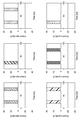
- FIG. 11 is a diagram showing the result of performing a simulation for reproducing the calculation of the multiplier unit in the second embodiment.
- the graph in the upper row shows the states of the qubits Q1 to Q3 in order from the left, and the graph in the lower row shows the states of the qubits Q4 to Q6 in order from the left.
- Q1 to Q6 shown in FIG. 11 correspond to Q1 to Q6 shown in FIG. 7. That is, Q1 to Q4 are inputs, and Q5 and Q6 are calculation results.
- Example 2 a simulation was performed in which (1,1,1,1) was input for 0 to 50 ns, and (1,0,1,1) was input for 50 ns to 100 ns.
- the calculation result is (1,1) for 0 to 50 ns and (1,0) for 50 ns to 100 ns, and it can be seen that the multiplication can be appropriately reproduced.
- the operation was simulated in the order of ns in order to shorten the simulation time, but it has been confirmed that the operation of the multiplier unit can be appropriately reproduced even when the operation is simulated in the order of ⁇ s. Is.
- the computer system 1 selects a calculation unit from the calculation unit group and causes the selected calculation unit to execute the calculation. This reduces the need for reconstruction according to the calculation content in the circuit configuration of the quantum computer.
- the arithmetic unit group includes a specific arithmetic unit in addition to the general-purpose arithmetic unit. Therefore, the surplus bits required for creating the target circuit by mapping the function to the general-purpose arithmetic unit become unnecessary.
- the instruction unit 126 can instruct the number of operations to be executed by the operation unit. At this time, the amount of increase in power consumption due to the increase in the number of operations can be reduced as compared with the amount of increase in power consumption in the classical computer.
- the specific calculation unit is selected for the purpose of matching the calculation content. If there is no specific arithmetic unit for, the general-purpose arithmetic unit is selected. As a result, an appropriate arithmetic unit (for example, a general-purpose arithmetic unit) is selected even when there is no specific arithmetic unit for the purpose that matches the arithmetic content.
- each of the plurality of arithmetic units selected by the selection unit 124 executes the arithmetic. As a result, the calculation can be executed more efficiently.
- the computer system 1 can also synchronize the operations by a plurality of arithmetic units.
- the quantum computer is an analog type, in the computer system 1 according to the present embodiment, it is not necessary to perform an arithmetic design synchronized with the clock as in the synchronization in the classical computer.
- the computer system 1 can also make operations by a plurality of arithmetic units asynchronous. This makes it possible to execute each of the operations of the plurality of operation units at more free timing.
- the arithmetic unit group includes a plurality of arithmetic units formed on the same substrate 310. Therefore, the design becomes easy, and the wiring of a plurality of arithmetic units formed on the same substrate 310 becomes easy to be routed. Further, by forming a plurality of arithmetic units on the same substrate, the latency of each arithmetic unit or the deviation of the timing of arithmetic is improved.
- the arithmetic unit group may include a plurality of arithmetic units formed on different substrates.
- FIG. 12 is a diagram showing the configuration of two substrates (first substrate 320 and second substrate 322) according to the first modification.
- a general-purpose arithmetic unit 312 is formed on the first substrate 320. Further, three specific arithmetic units 324, 326 and 328 are formed on the second substrate 322. In the present embodiment, the general-purpose arithmetic unit 312 and three specific arithmetic units 324, 326 and 328 constitute an arithmetic unit group.
- the table stored in the storage unit 100 is associated with information indicating the respective uses to each of the information indicating the three specific arithmetic units 324, 326 and 328.
- the selection unit 124 can refer to the table and select a specific calculation unit for the purpose that matches the calculation content. At this time, the selection unit 124 can select a plurality of specific arithmetic units. Alternatively, the selection unit 124 may select the general-purpose arithmetic unit 312 and at least one specific arithmetic unit.
- the execution unit 212 can cause each of the plurality of specific calculation units to execute the calculation.
- the execution unit 212 may cause another specific operation unit to execute a factorization operation while one specific operation unit is executing an operation for analyzing a protein.
- the arithmetic unit group includes a plurality of specific arithmetic units for different uses.
- the selection unit 124 can select a specific calculation unit for an application that matches the calculation content. As a result, among the plurality of specific arithmetic units, the specific arithmetic unit for the purpose that more closely matches the arithmetic content is selected. As a result, more appropriate operations are performed.
- the arithmetic unit group includes a plurality of arithmetic units formed on different substrates. Therefore, it is possible to arrange each substrate at a desired position according to the characteristics of the arithmetic unit formed on the substrate.
- a plurality of arithmetic units constituting the arithmetic unit group are arranged on two boards. Not limited to this, a plurality of arithmetic units constituting the arithmetic unit group may be arranged on three or more boards.
- FIG. 13 is a diagram showing an internal configuration of the refrigerator 30 according to the second modification.
- two substrates first substrate 330 and second substrate 334.
- the first substrate 330 is formed with the first arithmetic unit 332 provided with the quantum annealing element
- the second substrate 334 is formed with the second arithmetic unit 336 provided with the quantum gate element. ..
- the internal configuration of the refrigerator 30 is designed so that the temperature gradually decreases from the top to the bottom. That is, in the inside of the refrigerator 30, the lower the position, the lower the temperature.
- the first calculation unit 332 and the second calculation unit 336 are formed on substrates having different temperatures from each other. That is, each of the first substrate 330 and the second substrate 334 is attached to a stage (not shown) provided in different temperature regions. As a result, the temperatures of the first substrate 330 and the second substrate 334 are different from each other, and the temperatures of the first arithmetic unit 332 and the second arithmetic unit 336 are also different from each other. The temperatures of the first calculation unit 332 and the second calculation unit 336 are different from each other even when the respective calculation units execute the calculation.
- the second substrate 334 is arranged at a position lower than that of the first substrate 330. Therefore, the temperature of the second substrate 334 is lower than the temperature of the first substrate 330. As a result, the temperature of the second calculation unit 336 is lower than the temperature of the first calculation unit 332.
- the first substrate 330 is attached to a stage in a temperature range of about 0.1 K. Therefore, the temperature of the first substrate 330 and the first calculation unit 332 is about 0.1 K. Therefore, the quantum annealing element included in the first arithmetic unit 332 is in a superconducting state, and a quantum effect appears in the quantum annealing element. At this time, since the first calculation unit 332 can execute the calculation using the quantum effect or the thermal effect in the superconducting state, it can be said that the first calculation unit 332 is formed on the first substrate 330 having a temperature suitable for the calculation.
- the second substrate 334 is attached to the stage in the temperature range of less than 10 mK.
- the second calculation unit 336 formed on the second substrate 334 includes a quantum gate element, and can perform a calculation using a quantum effect or a thermal effect in a superconducting state at a temperature of less than 10 mK. Therefore, it can be said that the second calculation unit 336 is formed on the second substrate 334 having a temperature suitable for the calculation.
- the installation area in the temperature range of 10 mK is limited.
- An arithmetic unit such as the second arithmetic unit 336 needs to be arranged in a temperature region of 10 mK. Therefore, by arranging the first calculation unit 332 capable of appropriately executing the calculation at a temperature higher than 10 mK (for example, 0.1 K) in a temperature region higher than 10 mK, the space inside the refrigerator 30 can be efficiently created. It will be possible to utilize it.
- a Si quantum dot element or the like capable of unitary operation as a qubit may be arranged. Further, in the temperature region of 10 mK, elements of different quantum calculation methods such as those using the braiding theory, such as a topological insulator, may be arranged.
- the number of arithmetic units formed on the substrates having different temperatures is two. Not limited to this, the number of arithmetic units formed on substrates having different temperatures may be three or more.
- one measuring device 20 causes a calculation unit to perform a calculation.
- two or more measuring devices may cause the calculation unit to perform the calculation.
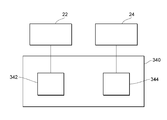
- FIG. 14 is a diagram showing a configuration of two measuring devices (first measuring device 22 and second measuring device 24) and a substrate 340 according to a third modification.
- the refrigerator is omitted. It is assumed that each of the first measuring device 22 and the second measuring device 24 has substantially the same function as the measuring device 20 shown in FIG. 3 and is communicably connected to the control device 10. ..
- the first calculation unit 342 is connected to the first measuring device 22, and the second calculation unit 344 is connected to the second measuring device 24. Therefore, the first measuring device 22 can cause the first calculation unit 342 to execute the calculation, and the second measuring device 24 can cause the second calculation unit 344 to execute the calculation.
- the first measuring device 22 and the second measuring device 24 of the first calculation unit 342 and the second calculation unit 344 so that the operations executed by the first calculation unit 342 and the second calculation unit 344 are synchronized with each other.
- Each can be made to perform an operation.
- a trigger signal may be input to the first measuring device 22 and the second measuring device 24.
- the first measuring device 22 and the second measuring device 24 cause the first calculation unit 342 and the second calculation unit 344 to execute the calculation in response to the trigger.
- the trigger signal may be generated, for example, by the indicator 126 of the control device 10 and transmitted to the first measuring device 22 and the second measuring device 24.
- the first arithmetic unit 342 and the second arithmetic unit 344 are arranged so that the arithmetic executed by the first arithmetic unit 342 and the second arithmetic unit 344 is asynchronous. You can also have each perform an operation.
- the number of measuring devices is two is illustrated, but the number of measuring devices may be three or more. Further, the number of arithmetic units connected to one measuring device may be two or more.
- each arithmetic unit has been described as executing the arithmetic in the refrigerator 30 in a superconducting state.
- the calculation unit is not limited to a device that executes a calculation in a superconducting state, and may be, for example, a device that can perform a calculation at room temperature.
- FIG. 15 is a schematic configuration diagram of the computer system 2 according to the fourth modification.
- the computer system 2 includes an arithmetic unit 40 in addition to the control device 10, the measuring device 20, and the refrigerator 30 included in the computer system 1 described with reference to FIG.
- the arithmetic unit 40 executes various operations regardless of the superconducting state in response to the instruction from the control device 10.
- the arithmetic unit 40 can execute arithmetic at room temperature, for example.
- the arithmetic unit 40 includes a communication unit 400, an execution unit 410, and an arithmetic unit 420.
- the communication unit 400 is an interface for connecting the control device 10 to another device.
- the communication unit 400 may be connected to a communication network such as LAN, WAN or the Internet. Further, the communication unit 400 may be connected to another device (for example, a control device 10 or the like) by a USB cable, a GPIB cable or the like.
- the communication unit 400 can transmit and receive various types of information. For example, the communication unit 400 can receive an instruction for calculation of the calculation unit by the control device 10. The communication unit 400 transmits the received information to the execution unit 410.
- the execution unit 410 may include, for example, a microcomputer including a ROM, RAM, CPU, and the like. Further, the execution unit 410 may have various configurations included in the execution unit 212 included in the measuring device 20.
- Execution unit 410 causes the calculation unit to execute various calculations. Specifically, based on the instruction from the control device 10, various arithmetic units included in the arithmetic unit 420 are made to execute the arithmetic.
- the calculation unit 420 includes various calculation units and executes various calculations according to the control by the execution unit 410.
- the arithmetic unit included in the arithmetic unit 420 may be a general-purpose arithmetic unit or a specific arithmetic unit.
- the arithmetic unit may be, for example, a LUT-based FPGA (Field-Programmable Gate Array) capable of efficiently executing logical operations, a workstation, an optical coherent singing machine, an ASIC (Application Specific Integrated Circuit) singing machine, or the like. ..
- the FPGA may be used as a general-purpose arithmetic unit or as a specific arithmetic unit.
- the arithmetic unit may include a device in which non-Von Neumann computing (for example, a singing machine, machine learning, etc.) is implemented in the FPGA.
- the arithmetic unit may execute an arithmetic such as simulated annealing.
- the arithmetic unit may be a circuit simulator that simulates the arithmetic of various arithmetic units that execute the arithmetic in the superconducting state such as the NOR unit described above.
- the arithmetic unit included in the arithmetic unit 40 and the arithmetic unit arranged in the refrigerator 30 may be a combination of only the specific arithmetic unit, or may be a combination of the specific arithmetic unit and the general-purpose arithmetic unit. It may be a combination of only general-purpose arithmetic units.
- the specific arithmetic unit included in the arithmetic unit 40 is provided in the form of a macro in the IP (Intellectual Property) core, and may be configured by various circuits according to the purpose of the arithmetic.
- a circuit may be configured by an electronic circuit simulator called SPICE (Simulation Program with Integrated Circuit Emphasis), and a specific arithmetic unit may output an arithmetic result by the circuit.
- SPICE Simulation Program with Integrated Circuit Emphasis
- the control device 10 may include a calculation unit, and the calculation unit may execute the calculation.
- the selection unit 124 can select a calculation unit included in the control device 10 or a calculation unit (for example, a specific calculation unit) arranged outside the control device 10.
- the selection unit 124 can select a calculation unit arranged outside the control device 10 when the calculation unit for the purpose matching the calculation content is arranged outside the control device 10.
- control device 10 the measuring device 20, and the arithmetic unit 40 are connected to each other so as to be communicable with each other mainly via the communication network 15.
- control device 10, the measuring device 20, and the arithmetic unit 40 may be communicably connected without going through the communication network 15.
- the acquisition unit 122 is mainly described as directly accepting the calculation content. Not limited to this, the acquisition unit 122 may estimate and acquire the calculation content based on the information related to the calculation content (for example, Hamiltonian or the like). Further, the acquisition unit 122 may acquire the calculation content based on the program that specifies the predetermined calculation content.
Landscapes
- Engineering & Computer Science (AREA)
- General Physics & Mathematics (AREA)
- Theoretical Computer Science (AREA)
- Physics & Mathematics (AREA)
- General Engineering & Computer Science (AREA)
- Mathematical Analysis (AREA)
- Mathematical Optimization (AREA)
- Pure & Applied Mathematics (AREA)
- Computing Systems (AREA)
- Computational Mathematics (AREA)
- Data Mining & Analysis (AREA)
- Evolutionary Computation (AREA)
- Condensed Matter Physics & Semiconductors (AREA)
- Mathematical Physics (AREA)
- Software Systems (AREA)
- Artificial Intelligence (AREA)
- Superconductor Devices And Manufacturing Methods Thereof (AREA)
Abstract
量子コンピュータの回路構成における演算内容に応じた再構成の必要性を低減することが可能なコンピュータシステム及び制御装置を提供する。演算内容を取得する取得部122と、超伝導状態の量子効果又は熱的効果を用いた演算をそれぞれ実行する複数の演算ユニットを含む演算ユニット群と、演算内容に基づいて、演算ユニット群から演算ユニットを選択する選択部124と、選択部により選択された演算ユニットに演算を実行させる実行部212と、を備えるコンピュータシステム。
Description
本発明は、コンピュータシステム及び制御装置に関する。
近年では、量子力学的な効果を利用した量子コンピュータの実現に向けた開発が行われている。例えば、特許文献1には、超伝導素子を用いた量子コンピュータについて記載されている。
量子コンピュータでは、演算内容に応じた回路構成が必要となる。このため、従来の量子コンピュータでは、演算内容が変わると、演算内容に応じた量子コンピュータの回路構成の再構成が必要となる。この結果、ユーザに負担が生じていたものと推測される。
そこで、本発明は、量子コンピュータの回路構成における演算内容に応じた再構成の必要性を低減することが可能なコンピュータシステム及び制御装置を提供することを目的とする。
本発明の一態様に係るコンピュータシステムは、演算内容を取得する取得部と、超伝導状態の量子効果又は熱的効果を用いた演算をそれぞれ実行する複数の演算ユニットを含む演算ユニット群と、演算内容に基づいて、演算ユニット群から演算ユニットを選択する選択部と、選択部により選択された演算ユニットに演算を実行させる実行部と、を備える。
この態様によれば、演算内容に応じた演算ユニットが選択され、その演算ユニットにより演算が実行される。このため、量子コンピュータの回路構成における演算内容に応じた再構成の必要性が低減される。
上記態様において、演算ユニット群は、汎用の演算ユニットである汎用演算ユニットと、特定の用途のための演算ユニットである特定演算ユニットとを含み、選択部は、演算ユニット群が演算内容に合致する用途のための特定演算ユニットを含まない場合には汎用演算ユニットを選択し、演算ユニット群が演算内容に合致する用途のための特定演算ユニットを含む場合には特定演算ユニットを選択してもよい。
この態様によれば、演算内容に応じて、より適切な演算ユニットが選択される。
上記態様において、演算ユニット群は、互いに異なる用途のための複数の特定演算ユニットを含み、選択部は、演算内容に合致する用途のための特定演算ユニットを選択してもよい。
この態様によれば、演算内容に応じて、より適切な演算ユニットが選択される。
上記態様において、演算ユニット群は、同一の基板上に形成されている複数の演算ユニットを含んでもよい。
この態様によれば、複数の演算ユニットが互いに異なる基板上に形成されている場合と比べて、設計が容易となる場合がある。
上記態様において、演算ユニット群は、互いに異なる基板上に形成されている複数の演算ユニットを含んでもよい。
この態様によれば、複数の演算ユニットのそれぞれに適した位置に、演算ユニットを配置することが可能になる。
上記態様において、互いに異なる基板上に形成されている複数の演算ユニットは、互いに異なる温度の基板上に形成されている複数の演算ユニットを含み、互いに異なる温度の基板上に形成されている複数の演算ユニットのそれぞれは、それぞれの演算ユニットによる演算に適した温度の基板上に形成されてもよい。
この態様によれば、冷凍機等に演算ユニットが配置される場合には、冷凍機内の空間をより効率よく利用することが可能になる。
上記態様において、選択部は、演算ユニット群から複数の演算ユニットを選択し、実行部は、選択部により選択された複数の演算ユニットのそれぞれに演算を実行させてもよい。
この態様によれば、複数の演算ユニットに演算を実行させることができるようになる。
上記態様において、実行部は、選択部により選択された複数の演算ユニットのそれぞれにより実行される演算が非同期となるように、選択部により選択された複数の演算ユニットのそれぞれに演算を実行させてもよい。
この態様によれば、複数の演算ユニットにそれぞれのタイミングで演算を実行させることができる。
上記態様において、実行部は、選択部により選択された複数の演算ユニットのそれぞれにより実行される演算が同期するように、選択部により選択された複数の演算ユニットのそれぞれに演算を実行させてもよい。
この態様によれば、複数の演算ユニットのそれぞれにより演算が実行されるタイミングを管理することが可能になる。
本発明の他の態様に係る制御装置は、演算内容を取得する取得部と、演算内容に基づいて、超伝導状態の量子効果又は熱的効果を用いた演算をそれぞれ実行する複数の演算ユニットを含む演算ユニット群から、演算ユニットを選択する選択部と、を備える。
この態様によれば、演算内容に応じた演算ユニットが選択され、その演算ユニットにより演算が実行される。このため、量子コンピュータの回路構成における演算内容に応じた再構成の必要性が低減される。
上記態様において、演算ユニット群は、汎用の演算ユニットである汎用演算ユニットと、特定の用途のための演算ユニットである特定演算ユニットとを含み、選択部は、演算ユニット群が演算内容に合致する用途のための特定演算ユニットを含まない場合には汎用演算ユニットを選択し、演算ユニット群が演算内容に合致する用途のための特定演算ユニットを含む場合には汎用演算ユニットを選択してもよい。
この態様によれば、演算内容に応じて、より適切な演算ユニットが選択される。
上記態様において、演算ユニット群は、互いに異なる用途のための複数の特定演算ユニットを含み、選択部は、演算内容に合致する用途のための特定演算ユニットを選択してもよい。
この態様によれば、演算内容に応じて、より適切な演算ユニットが選択される。
本発明によれば、量子コンピュータの回路構成における演算内容に応じた再構成の必要性を低減することが可能なコンピュータシステム及び制御装置を提供することができる。
添付図面を参照して、本発明の好適な実施形態について説明する。なお、各図において、同一の符号を付したものは、同一又は同様の構成を有する。
[第1実施形態]
図1は、本開示の一実施形態に係るコンピュータシステム1の概略構成図である。本実施形態に係るコンピュータシステム1は、主として、制御装置10、測定装置20及び冷凍機30を備える。制御装置10及び測定装置20は、通信ネットワーク15を介して、通信可能に接続されている。また、測定装置20は、冷凍機30に配置されている複数の演算ユニットに接続されている。
図1は、本開示の一実施形態に係るコンピュータシステム1の概略構成図である。本実施形態に係るコンピュータシステム1は、主として、制御装置10、測定装置20及び冷凍機30を備える。制御装置10及び測定装置20は、通信ネットワーク15を介して、通信可能に接続されている。また、測定装置20は、冷凍機30に配置されている複数の演算ユニットに接続されている。
通信ネットワーク15は、各種の態様を取り得る。通信ネットワーク15は、例えば、専用回線を通して相互に接続するデータ伝送ネットワーク(WAN)又はローカル・エリア・ネットワーク(LAN)等であってよい。本実施形態では、通信ネットワーク15は、公共ネットワークの代表のインターネットであるものとして説明する。なお、制御装置10及び測定装置20は、USB(Universal Serial Bus)ケーブル又はGPIB(General Purpose Interface Bus)ケーブル等で接続されても良い。
冷凍機30には、超伝導状態の量子効果又は熱的効果を用いた演算をそれぞれ実行する複数の演算ユニットを含む演算ユニット群が配置されている。本実施形態では、演算ユニット群が量子コンピュータを構成している。制御装置10は、冷凍機30に配置されている演算ユニット群から、演算を実行する演算ユニットを選択できる。測定装置20は、制御装置10により選択された演算ユニットに各種の演算を実行させる。以下、制御装置10、測定装置20及び冷凍機30の構成について詳細に説明する。
制御装置10は、演算内容に基づいて演算ユニットを選択し、選択した演算ユニットが演算を実行するように、測定装置20に指示することができる。制御装置10は、記憶部100、表示部105、入力部110、処理部120及び通信部130を備える。
記憶部100は、各種の情報を記憶している。記憶部100は、例えば、演算ユニットを選択するための情報を記憶している。具体的には、記憶部100は、演算ユニットとその演算ユニットの用途(例えば、因数分解及びタンパク質構造解析等の用途)とを対応付けたテーブルを記憶してよい。本実施形態では、テーブルには、複数の演算ユニットを示す情報と、それぞれの演算ユニットに対応付けられた用途を示す情報とが格納されている。記憶部100が記憶している各種の情報は、必要に応じて処理部120により参照される。
表示部105は、各種の画面を表示できる。例えば、表示部105は、演算内容を特定するための画面を表示できる。具体的には、表示部105は、各種の演算内容を表示して、チェックボックス式、スクロール式又はプルダウン式等の各種の形式でユーザが演算内容を特定できる画面を表示する。
入力部110は、ユーザの操作に応じて、各種の情報の入力を受け付ける。例えば、入力部110は、ユーザの操作に応じて演算内容を受け付ける。このとき、入力部110は、複数の演算内容を受け付けてもよい。入力部110が受け付けた各種の情報は、処理部120に伝達される。
処理部120は、各種の処理を実行する。具体的には、処理部120は、演算ユニット群から演算ユニットを選択して、選択した演算ユニットに演算を実行するように測定装置20に指示できる。処理部120は、取得部122、選択部124、指示部126及び表示制御部128を備える。
取得部122は、各種の情報を取得できる。具体的には、取得部122は、記憶部100から各種の情報を取得したり、入力部110が受け付けた各種の情報を取得したりできる。例えば、取得部122は、入力部110からユーザの操作に基づいて、演算内容を取得できる。このとき、取得部122は、複数の演算内容を取得してもよい。
選択部124は、取得部122が取得した演算内容に基づいて、冷凍機30に配置されている演算ユニット群から演算ユニットを選択することができる。具体的には、選択部124は、記憶部100に記憶されているテーブルを参照して、取得された演算内容に応じた演算ユニットを選択する。本実施形態では、演算ユニット群は、汎用の演算ユニットである汎用演算ユニットと、特定の用途のための演算ユニットである特定演算ユニットを含む。選択部124は、演算内容に応じて、汎用演算ユニット及び特定演算ユニットの少なくともいずれかを選択する。
具体的には、演算ユニット群が、取得された演算内容に合致する用途のための特定演算ユニットを含まない場合には、選択部124は、汎用演算ユニットを選択する。一方、演算ユニット群が、取得された演算内容に合致する用途のための特定演算ユニットを含む場合には、選択部124は、その特定演算ユニットを選択する。
また、選択部124は、演算ユニット群から複数の演算ユニットを選択できる。選択部124は、複数の特定演算ユニットを選択してもよいし、汎用演算ユニット及び少なくとも1つの特定演算ユニットを選択してもよい。このとき、選択部124は、複数の演算内容に基づいて、それぞれの演算内容に合致する用途のための演算ユニットを選択できる。あるいは、選択部124は、1つの演算内容に基づいて、その演算内容に合致する複数の演算ユニットを選択してもよい。すなわち、1つの演算内容に応じた演算が複数の演算ユニットに分担されてもよい。
指示部126は、演算ユニットによる演算の実行を指示することができる。具体的には、指示部126は、通信部130を介して測定装置20に各種の信号を伝送して、演算ユニットによる演算の実行を指示することができる。本実施形態では、指示部126は、選択部124により選択された演算ユニットによる演算の実行を指示する。また、指示部126は、例えばユーザの操作に基づいて、演算ユニットに演算を実行させる回数を指示してもよい。
さらに、指示部126は、複数の演算ユニットによる演算の実行を指示することができる。この場合、指示部126は、複数の演算ユニットによる演算の同期に関する指示を行うことができる。例えば、指示部126は、ユーザの操作に基づき、複数の演算ユニットのそれぞれによる演算のタイミングを指示してもよい。
表示制御部128は、表示部105の表示を制御する。具体的には、表示制御部128は、表示部105が表示する画面のデータを生成し、生成したデータを表示部105に伝達する。例えば、表示制御部128は、ユーザが演算内容を入力するための各種の画面のデータを生成して、生成したデータを表示部105に伝達できる。
通信部130は、各種の情報を送受信できる。例えば、通信部130は、通信ネットワーク15を介して、指示部126による指示を測定装置20に送信できる。
図2は、本実施形態に係る制御装置10のハードウェア構成の一例を示す図である。制御装置10は、処理部120に相当するCPU(Central Processing Unit)10aと、記憶部100に相当するRAM(Random Access Memory)10bと、記憶部100に相当するROM(Read Only Memory)10cと、通信部10dと、入力部10eと、表示部10fと、を有する。これらの各構成は、バスを介して相互にデータ送受信可能に接続される。なお、本例では制御装置10が一台のコンピュータで構成される場合について説明するが、制御装置10は、複数のコンピュータが組み合わされて実現されてもよい。また、図2で示す構成は一例であり、制御装置10はこれら以外の構成を有してもよいし、これらの構成のうち一部を有さなくてもよい。
CPU10aは、RAM10b又はROM10cに記憶されたプログラムの実行に関する制御やデータの演算、加工を行う処理部である。CPU10aは、演算内容を取得して演算ユニットを選択し、演算の実行を指示するプログラム(演算指示プログラム)を実行する処理部である。CPU10aは、入力部10eや通信部10dから種々のデータを受け取り、データの演算結果を表示部10fに表示したり、RAM10bに格納したりする。
RAM10bは、記憶部のうちデータの書き換えが可能なものであり、例えば半導体記憶素子で構成されてよい。RAM10bは、CPU10aが実行するプログラム、演算結果および演算に必要なデータといったデータを記憶してよい。なお、これらは例示であって、RAM10bには、これら以外のデータが記憶されていてもよいし、これらの一部が記憶されていなくてもよい。
ROM10cは、記憶部のうちデータの読み出しが可能なものであり、例えば半導体記憶素子で構成されてよい。ROM10cは、例えば演算指示プログラムや、書き換えが行われないデータを記憶してよい。
通信部10dは、制御装置10を他の機器に接続するインターフェースである。通信部10dは、インターネット等の通信ネットワークに接続されてよい。
入力部10eは、ユーザからデータの入力を受け付けるものであり、例えば、キーボード及びタッチパネルを含んでよい。
表示部10fは、各種の画面に表示するものであり、例えば、LCD(Liquid Crystal Display)により構成されてよい。表示部10fは、例えば、演算内容を入力するための画面等を表示してよい。
演算指示プログラムは、RAM10bやROM10c等のコンピュータによって読み取り可能な記憶媒体に記憶されて提供されてもよいし、通信部10dにより接続される通信ネットワークを介して提供されてもよい。制御装置10では、CPU10aが演算指示プログラムを実行することにより、図1を用いて説明した様々な動作が実現される。なお、これらの物理的な構成は例示であって、必ずしも独立した構成でなくてもよい。例えば、制御装置10は、CPU10aとRAM10bやROM10cが一体化したLSI(Large-Scale Integration)を備えていてもよい。
図3は、本実施形態に係る測定装置20及び冷凍機30の概略構成図である。
測定装置20は、演算ユニットに各種の演算を実行させる。本実施形態では、測定装置20は、制御装置10の指示部126による指示に基づいて、冷凍機30に配置されている各種の演算ユニットに演算を実行させることができる。より具体的には、測定装置20は、選択部124により選択された演算ユニットに演算を実行させる。測定装置20は、通信部200、制御部210、第1スイッチ220及び第2スイッチ222を備える。なお、第1スイッチ220と第2スイッチ222は、実際の構造として存在しても良いが、選択部124によって選択される状態を理解のし易さを向上するために便宜上示したものであっても良い。すなわち、第1スイッチ220及び第2スイッチ222は、実際の構造として存在しなくてもよい。
通信部200は、測定装置20を他の機器に接続するインターフェースである。本実施形態では、通信部200は、通信ネットワーク15に接続される。通信部200は、各種の情報を送受信できる。例えば、通信部200は、制御装置10による指示等を受信する。
制御部210は、各種の制御を実行する。制御部210は、例えば、ROM、RAM及びCPU等を備えるマイクロコンピュータ等を含んでよい。制御部210は、実行部212及びスイッチ制御部214を備える。なお、スイッチ制御部214は、実際の構造として存在しても良いが、選択部124によって選択される状態を理解のし易さを向上するために便宜上示したものであっても良い。汎用演算ユニット312及び特定演算ユニット318と実行部212とは、リン青銅線、Cu又はNbTi/CuNi等を素材とした低抵抗線、SCNi-CuNi等を素材とした高周波配線又は同軸ケーブル等、電気信号を伝搬するための配線で接続されている。スイッチ制御部214は、この2つの演算ユニットと実行部212との接続を制御するものとして便宜上示したが、実際の構造として存在しても良い。
実行部212は、演算ユニットに演算を実行させる。具体的には、実行部212は、制御装置10の指示に基づいて、演算ユニットに各種の信号を伝送して演算ユニットに演算を実行させる。実行部212は、信号発生器を備える。信号発生器は、各種の信号を発生する装置であり、例えば、AWG(Arbitrary Waveform Generator:任意波形発生器)、オシレータ及び直流電源等の各種の装置を含む。また、実行部212は冷凍機30の内部に配置されてもよい。
また、実行部212は、選択部124により選択された複数の演算ユニットのそれぞれにより実行される演算が同期するように、各演算ユニットに演算を実行させることができる。具体的には、実行部212は、各演算ユニットに信号を入力するタイミングを調整することにより、複数の演算ユニットによる演算のタイミングを管理することができる。例えば、実行部212は、複数の演算ユニットに、同一のタイミングで演算を開始させたりすることができる。
また、実行部212は、選択部124により選択された複数の演算ユニットのそれぞれにより実行される演算が非同期となるように、各演算ユニットに演算を実行させることができる。例えば、実行部212は、複数の演算ユニットに、異なるタイミングで演算を開始させてもよい。
スイッチ制御部214は、制御装置10の指示に基づいて、各種の公知のスイッチング素子により構成される第1スイッチ220及び第2スイッチ222の状態を制御する。具体的には、スイッチ制御部214は、演算を実行させる演算ユニットに接続されたスイッチを導通状態に制御し、演算を実行させない演算ユニットに接続されたスイッチを開放状態に制御する。例えば、第1スイッチ220に接続された演算ユニットが演算を実行し、第2スイッチ222に接続された演算ユニットが演算を実行しない場合には、スイッチ制御部214は、第1スイッチ220を導通状態に制御して、第2スイッチ222を開放状態に制御する。なお、第1スイッチ220、第2スイッチ222及びスイッチ制御部214は実際の構造として存在しても良いが、選択部124によって選択される状態を理解のし易さを向上するために便宜上示したものであっても良い。すなわち、第1スイッチ220、第2スイッチ222及びスイッチ制御部214は、実際の構造として存在しなくてもよい。
冷凍機30は、極低温を実現できる冷凍機であり、例えば3He-4He希釈冷凍法を用いた冷凍機であってよい。冷凍機30の内部の温度は、4K(より正確には、大気圧化での4He液体の沸点である4.2K)以下の温度であり得る。また、冷凍機30は、所定の温度に調整される基板310を備える。本実施形態では、基板310の温度は、数mK~数十mKの温度である。なお、基板310の温度は、これに限定されるものではなく、例えば4.2K程度あるいは1K程度の温度であってもよい。
本実施形態では、演算ユニット群は、同一の基板310上に形成されている複数の演算ユニットを含む。演算ユニットは、超伝導材料を含み、超伝導状態で量子効果又は熱的効果を用いた演算を実行する。より具体的には、演算ユニットは、演算ユニットの温度が超伝導材料の超伝導転移温度以下である場合に、量子アニーリング等を用いた演算を実行できる。演算ユニットには、読み出し回路が接続されており、演算結果等が適宜読み出される。読み出し回路は、例えば、基板310に形成されている。なお、演算ユニットは、量子アニーリングに限らず、例えば、イオントラップ、コヒーレントイジングマシン、量子ゲート素子、量子ドット、NV(nitrogen vacancy)センター及びトポロジカル絶縁体(majorana fermion)等の少なくともいずれかを利用してもよい。
本実施形態では、基板310上には、汎用の演算ユニットである汎用演算ユニット312と、特定の用途のための演算ユニットである特定演算ユニット318とが形成されている。すなわち、本実施形態では、演算ユニット群は、汎用演算ユニット及び特定演算ユニットを含む。汎用演算ユニット312及び特定演算ユニット318のそれぞれが演算を実行する際には、汎用演算ユニット312及び特定演算ユニット318のそれぞれの温度は、基板310の温度と同一になっているものとする。
汎用演算ユニット312及び特定演算ユニット318のそれぞれは、測定装置20に電気的に接続されている。具体的には、汎用演算ユニット312及び特定演算ユニット318のそれぞれは、同軸ケーブル又はツイストペアケーブルを通じて、測定装置20の第1スイッチ220及び第2スイッチ222に接続されている。なお、第1スイッチ220及び第2スイッチ222は、便宜的に示したものであり、汎用演算ユニット312及び特定演算ユニット318のそれぞれに接続された同軸ケーブル又はツイストペアケーブル等、電気信号を伝搬するための配線は、測定装置20に直接接続されていても良い。
汎用演算ユニット312は、例えば、量子ゲート素子等を備えた回路であってよい。この場合、1枚の基板310を図示しているが、複数の基板が積層していてもよく、複数の基板が貼り合わせられてもよい。このとき、インターポーザあるいはTSV(Through Silicon Via)及びバンプを用いた構成等の各種の構成が実現され得る。
特定演算ユニット318は、特定の用途に適した回路構成を備えてよい。例えば、特定演算ユニット318は、解く問題に対応するハミルトニアンの形を実装することに適した回路構成を備えてよい。この場合、特定演算ユニット318が備える回路構成は、例えば、量子ビットで構成された複数の格子(例えば、図4に示したような格子)を含んでよい。このとき、特定演算ユニット318を構成する複数の量子ビットの間の結合及び格子の間の結合には、固定結合が利用されてもよい。すなわち、特定演算ユニット318を構成する複数の量子ビットの間の結合及び格子の間の結合は、固定されており、変更できない結合であってもよい。
特定演算ユニット318の用途は、例えば、論理演算(例えば、NOR演算、NAND演算、OR演算及びAND演算等)、乗算、因数分解、タンパク質構造解析、ナップザック最適化問題及びポートフォリオ最適化問題等の各種の用途であってよい。
図4は、本実施形態に係る汎用演算ユニット312の概略構成図である。本実施形態に係る汎用演算ユニット312は、4つの格子(第1格子313、第2格子314、第3格子315、第4格子316)により構成されたキメラグラフを備える。それぞれの格子は、縦及び横に4つの量子ビットが並べられた構成を有している。なお、図4には、4つの格子が示されているが、汎用演算ユニット312が備える格子の数は3つ以下であってもよいし、5つ以上であってもよい。
具体的に説明すると、それぞれの格子は、横に伸びている4つの第1量子ビット301と、縦に伸びている4つの第2量子ビット302と、16個の可変結合器303を備えている。可変結合器303は、1つの第1量子ビット301と1つの第2量子ビット302との結合するもので、その結合は適宜調整され得る。可変結合器303による結合に応じて、第1量子ビット301と第2量子ビット302とが相互作用する。
なお、それぞれの格子が備える4つの第1量子ビット301のそれぞれは、別個の量子ビットとして機能する。各第1量子ビット301は、可変結合器により他の量子ビットに接続され、他の量子ビットとの相互作用を有している。また、それぞれの格子が備える4つの第2量子ビット302のそれぞれは、別個の量子ビットとして機能する。各第2量子ビット302は、可変結合器により他の量子ビットに接続され、他の量子ビットとの相互作用を有している。
また、それぞれの量子ビットの端部は、他の格子に含まれる対面する量子ビットの端部と接続され得る。例えば、第1格子313に含まれる左端の第2量子ビット302の端部305は、第3格子315に含まれる左端の第2量子ビットの端部306と接合され得る。このように量子ビット同士が接続されることにより複数の格子が接続され、複数の格子を用いた演算が実現される。
汎用演算ユニット312において演算が実行される際には、演算内容に応じて、使用される格子の数が適宜調整される。例えば、演算内容が3つの量子ビットを必要とする内容である場合には、1つの格子が使用される。また、演算内容が7つの量子ビットを必要とする内容である場合には、例えば4つの格子が使用される。
本実施形態では、汎用演算ユニット312はキメラグラフを用いた演算を実行するが、キメラグラフを用いた演算では、ユーザにより解くべき問題に応じたハミルトニアンが設定され、そのハミルトニアンがキメラグラフにマッピングされる。例えば、設定されるハミルトニアンH1が、H1=Σn=3Jijσiσj+Σhiσjで表される場合には、3つの量子ビットが必要となるため、1つの格子が用いられる。また、設定されるハミルトニアンH2が、H2=Σn=7Jijσiσj+Σhiσjで表される場合には、例えば7つの量子ビットが必要となるため、3つの格子が用いられる。ここで、σiはサイトiのスピン、hiはサイトiの磁場、Jijはサイトi及びサイトjのスピンの相互作用、nは全サイト数を示している。
また、汎用演算ユニット312は、1つ又は複数(例えば3つ)のLUT(Look Up Table)を含み、所望の演算を実行できる構成を含んでも良い。汎用演算ユニット312が複数のLUTを含む場合、複数のLUTのうちの少なくとも2つのLUTが互いに接続されてよい。このとき、選択部124によって汎用演算ユニット312が選択された後、表示部105に演算内容を指定するための画面が表示され、演算内容をユーザにより設計するモードが選択されてよい。演算内容に応じたLUTの接続方法(複数のLUTの間の接続方法)をユーザが設定することで、指示部126が汎用演算ユニット312に演算の実行を指示し、汎用演算ユニット312で演算が実行されることとなる。
図5は、本実施形態に係るコンピュータシステム1による処理の流れを示すフローチャートである。
まず、入力部110は、ユーザの操作に基づき、演算内容の入力を受け付ける(ステップS101)。次いで、取得部122は、ステップS101において受け付けられた演算内容を取得する(ステップS103)。
次いで、選択部124は、ステップS103において取得された演算内容に合致する用途の特定演算ユニットがあるか否かを判定する(ステップS105)。選択部124が、演算内容に合致する用途の特定演算ユニットがないことを判定した場合(ステップS105:NO)、ステップS107に進む。一方、選択部124が、演算内容に合致する用途の特定演算ユニットがあることを判定した場合(ステップS105:YES)、ステップS109に進む。
ステップS105においてNOと判定されると、選択部124は、演算ユニット群から汎用演算ユニットを選択する(ステップS107)。一方、ステップS105においてYESと判定されると、選択部124は、演算ユニット群から演算内容に合致する用途の特定演算ユニットを選択する(ステップS109)。
ステップS107又はステップS109において選択部124が演算ユニットを選択すると、指示部126は、選択された演算ユニットによる演算の実行の指示を生成する(ステップS111)。次いで、通信部130は、通信ネットワーク15を介して、選択された演算ユニットによる演算の実行の指示を測定装置20に送信する(ステップS113)。次いで、測定装置20の通信部200は、指示を受信し、実行部212は、受信した指示に基づいて、選択された演算ユニットに演算を実行させる(ステップS115)。これにより、冷凍機30に配置される演算ユニットにおいて、演算内容に応じた演算が実行される。演算ユニットにより演算が実行されると、図5に示す処理が終了する。なお、ここでは記載を省略しているが、演算結果は、測定装置20の状態観測(状態読出し)を担う測定機器(図示しない。)によって観測され、通信ネットワーク15を介して、制御装置10に送信されてよい。さらに、演算結果は、表示部105に表示されたり、記憶部100に記憶されたりしてもよい。
<実施例1>
実施例1では、冷凍機30に2つの演算ユニットを配置して実験を行った。本実施例では、2つの演算ユニットは、NOR演算を実行する演算ユニット(以下、「NORユニット」とも称する。)及び乗算を実行する演算ユニット(以下、「乗算器ユニット」とも称する。)である。本実施例では、NORユニット及び乗算器ユニットのそれぞれを、冷凍機30において10mKまで冷却し、超伝導状態でNORユニット及び乗算器ユニットのそれぞれに演算を実行させた。本実施例では、演算ユニットの選択(NORユニット又は乗算器ユニットの選択)及び演算ユニットによる演算の実行の指示等には、制御装置10に搭載されたソフトウェア「LabVIEW(登録商標)」を用いた。
実施例1では、冷凍機30に2つの演算ユニットを配置して実験を行った。本実施例では、2つの演算ユニットは、NOR演算を実行する演算ユニット(以下、「NORユニット」とも称する。)及び乗算を実行する演算ユニット(以下、「乗算器ユニット」とも称する。)である。本実施例では、NORユニット及び乗算器ユニットのそれぞれを、冷凍機30において10mKまで冷却し、超伝導状態でNORユニット及び乗算器ユニットのそれぞれに演算を実行させた。本実施例では、演算ユニットの選択(NORユニット又は乗算器ユニットの選択)及び演算ユニットによる演算の実行の指示等には、制御装置10に搭載されたソフトウェア「LabVIEW(登録商標)」を用いた。
図6は、実施例1において、NORユニットにNOR演算を実行させた結果を示す図である。本実施例では、入力(0,0)、(0,1)、(1,0)及び(1,1)のNOR演算を、NORユニットにそれぞれ1000回ずつ実行させた。図6には、4つの演算結果のグラフが示されており、上から順に入力(0,0)、(0,1)、(1,0)及び(1,1)の演算結果が示されている。図中のX及びYは、入力(X,Y)を示しており、Sは演算結果を示している。また、グラフの横軸は、(X,Y,S)を示しており、縦軸は演算結果のカウント数を示している。図6に示すように、いずれの演算においても、正しい演算結果が一番多くカウントされている。したがって、本実施例では、NORユニットにおいて、適切に演算が実行されたといえる。
次いで、図7及び図8を参照して、乗算器ユニットによる演算結果について説明する。図7は、実施例1における乗算器ユニットの演算内容を説明するための図である。図7に示すX、Y、Z及びDのそれぞれは、乗算器ユニットの入力に対応している。また、C及びSは、乗算器ユニットの演算結果に対応している。図7に示す回路は、乗算器ユニットの入力及び出力の関係を模試的に示したものであり、X、Y、Z、D、C及びSのそれぞれは、量子ビット(Q1~Q6)により実現される。
図8は、実施例1において乗算器ユニットに乗算を実行させた結果を示す図である。図8には、入力(X,Y,Z,D)に対する演算結果(C,S)が示されている。本実施例では、乗算器ユニットに、(0,0,0,0)~(1,1,1,1)を入力とする乗算を実行させた。図8に示すように、いずれの演算においても、適切な演算結果が得られていることが分かる。
本実施例では、NORユニット及び乗算器ユニットの2つの演算ユニットから構成される演算ユニット群から、演算内容に応じた演算ユニットを選択して、選択した演算ユニットに演算を実行させた。その結果、いずれの演算ユニットにおいても、適切に演算が実行された。
<実施例2>
実施例2では、実施例1においてNORユニット及び乗算器ユニットのそれぞれが実行した演算を模擬するシミュレーションを行った。
実施例2では、実施例1においてNORユニット及び乗算器ユニットのそれぞれが実行した演算を模擬するシミュレーションを行った。
まず、NORユニットによる演算を模擬したシミュレーションを行った。具体的には、3つの量子ビットを形成するループのそれぞれに対応する回路を用意して、それぞれの回路に各々並走する部分を有する電流線路へ電流(Ih1,Ih2,Ih3)を流して磁束を発生させ、3つの量子ビットの各ループへ臨界電流を誘起させた。各量子ビットは、演算結果(それぞれのループを流れる臨界電流Iq1,Iq2,Iq3)がNORの関係となるように相互作用を有している。この回路シミュレーションでは、Ih1,Ih2,Ih3によって各量子ビットに異なる臨界電流が流れることとなる。換言すれば、Ih1とIh2とが流れることで誘起される磁束でNORユニットの入力を生じさせ、Ih3は出力を観測するための電流を誘起する磁束を与えているともいえる。そして、それぞれの量子ビットのループに結合している読み出し回路を介して、それぞれの量子ビットのループを流れる電流(以下では、単に「量子ビットの電流」とも称する。)の値が閾値を超えているか否かに基づき、量子ビットの状態(0又は1)を計測した。
図9は、実施例2におけるシミュレーションにおいて、3つの回路に流した電流(Ih1,Ih2及びIh3)を示す図である。0~50nsでは(1,1,0)の演算、50~100nsでは(1,0,0)の演算をシミュレーションしている。0~50nsでは、(1,1,0)の演算が実現されるように電流Ih1,Ih2,Ih3を3つの量子ビットに並走する部分を有する各電流線路へ流した。50~100nsでは、(1,0,0)の演算が実現されるように電流Ih1,Ih2,Ih3を3つの量子ビットに並走する部分を有する各電流線路へ流した。
図10は、実施例2におけるシミュレーションにおいて、3つの量子ビットのループに流れる電流を示す図である。図10に示す3つのグラフは、左から順にIh1,Ih2及びIh3の電流が流れる回路に対応する量子ビットの電流Iq1,Iq2及びIq3を示すグラフである。本実施例では、0μAを閾値として、量子ビットの状態(0又は1)を計測した。具体的には、量子ビットの電流値が0μAより低い場合には、その量子ビットを1として計測し、量子ビットの電流値が0μA以上である場合には、その量子ビットを0として計測した。図10から各量子ビットの状態を読み取ると、0~50nsでは3つの量子ビットの状態は(1,1,0)となり、50~100nsでは3つの量子ビットの状態は(1,0,0)となっていることが分かる。したがって、NORユニットの演算を適切に再現できていることが分かる。なお、本実施例では、シミュレーションの時間を短縮するためにnsのオーダーで演算をシミュレーションしたが、μsのオーダーで演算をシミュレーションした場合においても、NORユニットの演算を適切に再現できることは確認済みである。
図11は、実施例2において、乗算器ユニットの演算を再現するシミュレーションを行った結果を示す図である。上の段のグラフは、左から順にQ1~Q3の量子ビットの状態を示し、下の段のグラフは左から順にQ4~Q6の量子ビットの状態を示している。ここでは量子ビットの状態を読みだした時に、量子ビットの状態が1であれば正の電圧が出力されるような演算を行った。ここで、図11に示すQ1~Q6は、図7に示したQ1~Q6に対応している。すなわち、Q1~Q4が入力であり、Q5及びQ6が演算結果である。実施例2では、0~50nsでは(1,1,1,1)を入力とする演算、50ns~100nsでは(1,0,1,1)を入力とする演算のシミュレーションを行った。図11を参照すると、演算結果は、0~50nsでは(1,1)となり、50ns~100nsでは(1,0)となっており、乗算を適切に再現できていることが分かる。なお、本実施例では、シミュレーションの時間を短縮するためにnsのオーダーで演算をシミュレーションしたが、μsのオーダーで演算をシミュレーションした場合においても、乗算器ユニットの演算を適切に再現できることは確認済みである。
<効果>
本実施形態によれば、コンピュータシステム1は、演算ユニット群から演算ユニットを選択して、選択した演算ユニットに演算を実行させる。これにより、量子コンピュータの回路構成における演算内容に応じた再構成の必要性が低減される。
本実施形態によれば、コンピュータシステム1は、演算ユニット群から演算ユニットを選択して、選択した演算ユニットに演算を実行させる。これにより、量子コンピュータの回路構成における演算内容に応じた再構成の必要性が低減される。
また、本実施形態によれば、演算ユニット群は、汎用演算ユニットに加えて、特定演算ユニットを含む。このため、汎用演算ユニットに機能をマッピングして目的の回路を作る際に必要となる余剰ビットが不要となる。
また、本実施形態によれば、指示部126は、演算ユニットに実行させる演算回数を指示することができる。このとき、演算回数が増加することによる消費電力量の増加量は、古典コンピュータにおける消費電力量の増加量と比べて低減され得る。
また、本実施形態によれば、取得部122により取得された演算内容に合致する用途のための特定演算ユニットがある場合には、その特定演算ユニットが選択され、演算内容に合致する用途のための特定演算ユニットがない場合には、汎用演算ユニットが選択される。これにより、演算内容に合致する用途の特定演算ユニットがない場合にも、適切な演算ユニット(例えば、汎用演算ユニット)が選択される。
また、本実施形態によれば、選択部124により選択された複数の演算ユニットのそれぞれが、演算を実行する。これにより、より効率よく演算が実行され得る。
また、本実施形態によれば、コンピュータシステム1は、複数の演算ユニットによる演算を同期させることもできる。このとき、量子コンピュータはアナログ式であるため、本実施形態に係るコンピュータシステム1では、古典コンピュータにおける同期のように、クロックに同期させた演算設計を行う必要がない。
また、本実施形態によれば、コンピュータシステム1は、複数の演算ユニットによる演算を非同期にすることもできる。これにより、複数の演算ユニットのそれぞれの演算を、より自由なタイミングで実行させることが可能になる。
また、本実施形態によれば、演算ユニット群は、同一の基板310上に形成されている複数の演算ユニットを含む。このため、設計が容易となったり、同一の基板310上に形成されている複数の演算ユニットの配線の引き回しが容易となったりする。また、複数の演算ユニットが同一の基板上に形成されることにより、それぞれの演算ユニットのレイテンシーあるいは演算のタイミングのずれ等が向上する。
[第1変形例]
上記実施形態では、1つの基板上に演算ユニット群を構成する全ての演算ユニットが形成されるものとして説明した。これに限らず、演算ユニット群は、互いに異なる基板上に形成されている複数の演算ユニットを含んでよい。
上記実施形態では、1つの基板上に演算ユニット群を構成する全ての演算ユニットが形成されるものとして説明した。これに限らず、演算ユニット群は、互いに異なる基板上に形成されている複数の演算ユニットを含んでよい。
図12は、第1変形例に係る2つの基板(第1基板320及び第2基板322)の構成を示す図である。第1基板320には、汎用演算ユニット312が形成されている。また、第2基板322には、3つの特定演算ユニット324,326及び328が形成されている。本実施形態では、汎用演算ユニット312及び3つの特定演算ユニット324,326及び328が演算ユニット群を構成している。
本実施形態では、記憶部100に記憶されているテーブルには、3つの特定演算ユニット324,326及び328を示す情報のそれぞれに、それぞれの用途を示す情報が対応付けられている。選択部124は、テーブルを参照して、演算内容に合致する用途の特定演算ユニットを選択できる。このとき、選択部124は、複数の特定演算ユニットを選択することができる。あるいは、選択部124は、汎用演算ユニット312及び少なくとも1つの特定演算ユニットを選択することもできる。
また、本実施形態では、実行部212は、複数の特定演算ユニットのそれぞれに演算を実行させることができる。例えば、実行部212は、1つの特定演算ユニットがタンパク質を解析する演算を実行させている際に、別の特定演算ユニットに因数分解の演算を実行させてよい。
本実施形態によれば、演算ユニット群が、互いに異なる用途のための複数の特定演算ユニットを備えている。さらに、選択部124は、演算内容に合致する用途のための特定演算ユニットを選択できる。これにより、複数の特定演算ユニットの中で、より演算内容に合致した用途の特定演算ユニットが選択される。この結果、より適切な演算が実行される。
また、本実施形態によれば、演算ユニット群は、互いに異なる基板上に形成されている複数の演算ユニットを含む。このため、基板に形成された演算ユニットの特性等に応じて、それぞれの基板を所望の位置に配置することが可能となる。
本実施形態では、演算ユニット群を構成する複数の演算ユニットが2つの基板に配置されるものとして説明した。これに限らず、演算ユニット群を構成する複数の演算ユニットは、3つ以上の基板に配置されてもよい。
また、本実施形態では、第2基板322には、3つの特定演算ユニットが形成されるものとして説明したが、1つの基板に4つ以上の特定演算ユニットが形成されてもよいし、2つ以下の特定演算ユニットが形成されてもよい。また、1つの基板には、2つ以上の汎用演算ユニットが配置されてもよい。
[第2変形例]
第1変形例では、複数の基板のそれぞれに演算ユニットが形成される例について説明した。冷凍機30において複数の基板が配置される場合には、それぞれの基板が異なる温度領域に配置されてもよい。
第1変形例では、複数の基板のそれぞれに演算ユニットが形成される例について説明した。冷凍機30において複数の基板が配置される場合には、それぞれの基板が異なる温度領域に配置されてもよい。
図13は、第2変形例に係る冷凍機30の内部構成を示す図である。冷凍機30には、2つの基板(第1基板330及び第2基板334)が異なる温度領域に配置されている。第1基板330には、量子アニーリング素子を備えた第1演算ユニット332が形成されており、第2基板334には、量子ゲート素子を備えた第2演算ユニット336が形成されているものとする。
ここでは、冷凍機30の内部構成は、上から下に向かうにつれて徐々に温度が低くなる設計となっているものとする。すなわち、冷凍機30の内部において、位置が低くなるほど、温度が低くなっている。
本実施形態では、第1演算ユニット332及び第2演算ユニット336は、互いに異なる温度の基板上に形成されている。すなわち、第1基板330及び第2基板334のそれぞれは、互いに異なる温度領域に設けられたステージ(図示しない。)に張り付けられている。この結果、第1基板330及び第2基板334の温度は、互いに異なる温度になっており、第1演算ユニット332及び第2演算ユニット336の温度も、互いに異なる温度になっている。なお、第1演算ユニット332及び第2演算ユニット336の温度は、それぞれの演算ユニットが演算を実行する際にも、互いに異なる温度になっている。
また、本実施形態では、第2基板334は、第1基板330よりも低い位置に配置されている。このため、第2基板334の温度は、第1基板330の温度よりも低くなっている。この結果、第2演算ユニット336の温度は、第1演算ユニット332の温度よりも低くなっている。
より詳細に説明すると、第1基板330は、0.1K程度の温度領域のステージに張り付けられている。このため、第1基板330及び第1演算ユニット332の温度は0.1K程度の温度になっている。このため、第1演算ユニット332が備える量子アニーリング素子は超伝導状態となり、量子アニーリング素子に量子効果が現れる。このとき、第1演算ユニット332は、超伝導状態の量子効果又は熱的効果を用いた演算を実行できるため、演算に適した温度の第1基板330上に形成されているといえる。
一方、第2基板334は、10mK未満の温度領域のステージに張り付けられている。第2基板334上に形成されている第2演算ユニット336は、量子ゲート素子を備えており、10mK未満の温度では、超伝導状態の量子効果又は熱的効果を用いた演算を実行できる。このため、第2演算ユニット336は、演算に適した温度の第2基板334上に形成されているといえる。
冷凍機30の内部では、10mKの温度領域の設置面積には限りがある。第2演算ユニット336のような演算ユニットは、10mKの温度領域に配置される必要がある。そこで、10mKよりも高い温度(例えば、0.1K)において適切に演算を実行可能な第1演算ユニット332を10mKよりも高い温度領域に配置することにより、冷凍機30の内部の空間を効率よく活用することが可能となる。
なお、10mKの温度領域には、量子ビットとしてユニタリー操作が可能なSiの量子ドット素子等が配置されてもよい。また、10mKの温度領域には、トポロジカル絶縁体等、組み紐理論を利用するような異なる量子計算方法の素子等が配置されても良い。
また、本実施形態では、互いに異なる温度の基板上に形成されている演算ユニットの数が2つであるものとして説明した。これに限らず、互いに異なる温度の基板上に形成されている演算ユニットの数は、3つ以上であってもよい。
[第3変形例]
上記実施形態では、1つの測定装置20が演算ユニットに演算を実行させるものとして説明した。これに限らず、2つ以上の測定装置が演算ユニットに演算を実行させてもよい。
上記実施形態では、1つの測定装置20が演算ユニットに演算を実行させるものとして説明した。これに限らず、2つ以上の測定装置が演算ユニットに演算を実行させてもよい。
図14は、第3変形例に係る2つの測定装置(第1測定装置22及び第2測定装置24)と、基板340との構成を示す図である。図14では、冷凍機が省略されている。第1測定装置22及び第2測定装置24のそれぞれは、図3に示した測定装置20と実質的に同一の機能を有しており、制御装置10に通信可能に接続されているものとする。
基板340には、2つの演算ユニット(第1演算ユニット342及び第2演算ユニット344)が形成されている。第1演算ユニット342は、第1測定装置22に接続されており、第2演算ユニット344は、第2測定装置24に接続されている。したがって、第1測定装置22は、第1演算ユニット342に演算を実行させることができ、第2測定装置24は、第2演算ユニット344に演算を実行させることができる。
このとき、第1測定装置22及び第2測定装置24は、第1演算ユニット342及び第2演算ユニット344により実行される演算が同期するように、第1演算ユニット342及び第2演算ユニット344のそれぞれに演算を実行させることができる。例えば、第1測定装置22及び第2測定装置24にトリガーとなる信号が入力され得る。このとき、第1測定装置22及び第2測定装置24は、そのトリガーに応じて第1演算ユニット342及び第2演算ユニット344に演算を実行させる。これにより、第1演算ユニット342及び第2演算ユニット344により実行される演算が同期する。トリガーとなる信号は、例えば、制御装置10の指示部126により生成され、第1測定装置22及び第2測定装置24に送信されてよい。
なお、第1測定装置22及び第2測定装置24は、第1演算ユニット342及び第2演算ユニット344により実行される演算が非同期となるように、第1演算ユニット342及び第2演算ユニット344のそれぞれに演算を実行させることもできる。
本実施形態では、測定装置の数が2つである場合を例示したが、測定装置の数は3つ以上であってよい。また、1つの測定装置に接続される演算ユニットの数は2つ以上であってもよい。
[第4変形例]
上記実施形態では、いずれの演算ユニットも冷凍機30において超伝導状態で演算を実行するものとして説明した。演算ユニットは、超伝導状態で演算を実行するデバイスに限らず、例えば、室温において演算を実行可能なデバイス等であって良い。
上記実施形態では、いずれの演算ユニットも冷凍機30において超伝導状態で演算を実行するものとして説明した。演算ユニットは、超伝導状態で演算を実行するデバイスに限らず、例えば、室温において演算を実行可能なデバイス等であって良い。
図15は、第4変形例に係るコンピュータシステム2の概略構成図である。コンピュータシステム2は、図1を用いて説明したコンピュータシステム1が備える制御装置10、測定装置20及び冷凍機30に加えて、演算装置40を備える。
演算装置40は、制御装置10による指示に応じて、超伝導状態に依らない各種の演算を実行する。本実施形態では、演算装置40は、例えば室温において演算を実行できるものとする。演算装置40は、通信部400、実行部410及び演算部420を備える。
通信部400は、制御装置10を他の機器に接続するインターフェースである。通信部400は、LAN、WAN又はインターネット等の通信ネットワークに接続されてよい。また、通信部400は、USBケーブル又はGPIBケーブル等によって他の装置(例えば制御装置10等)に接続されてもよい。通信部400は、各種の情報を送受信できる。例えば、通信部400は、制御装置10による演算ユニットの演算の指示を受信できる。通信部400は、受信した情報を実行部410に伝達する。
実行部410は、例えば、ROM、RAM及びCPU等を備えるマイクロコンピュータ等を含んでよい。また、実行部410は、測定装置20が備える実行部212が有する各種の構成を有してよい。
実行部410は、演算ユニットに各種の演算を実行させる。具体的には、制御装置10による指示に基づいて、演算部420が備える各種の演算ユニットに演算を実行させる。
演算部420は、各種の演算ユニットを備え、実行部410による制御に応じて、各種の演算を実行する。演算部420が備える演算ユニットは、汎用演算ユニットであってもよいし、特定演算ユニットであってよい。
演算ユニットは、例えば、論理演算を効率よく実行できるLUTベースのFPGA(Field-Programmable Gate Array)、ワークステーション、光コヒーレントイジングマシン、ASIC(Application Specific Integrated Circuit)により機能するイジングマシン等であってよい。ここで、FPGAは、汎用演算ユニットとして用いられてもよいし、特定演算ユニットとして用いられてもよい。また、演算ユニットは、FPGAに非ノイマン型コンピューティング(例えば、イジングマシン及び機械学習等)を実装したデバイスを含んでよい。また、演算ユニットは、シミュレーテッドアニーリング等の演算を実行してもよい。さらに、演算ユニットは、上述したNORユニット等の超伝導状態で演算を実行する各種の演算ユニットの演算をシミュレーションする回路シミュレータであってもよい。
演算装置40が備える演算ユニットと冷凍機30に配置された演算ユニットとは、特定演算ユニットのみの組み合わせであってもよいし、特定演算ユニットと汎用演算ユニットとの組み合わせであってもよいし、汎用演算ユニットのみの組み合わせであってもよい。
また、演算装置40が備える特定演算ユニットは、IP(Intellectual Property)コアにおけるマクロの形態で提供され、演算の目的に応じた各種の回路により構成されてもよい。例えば、SPICE(Simulation Program with Integrated Circuit Emphasis)と呼ばれる電子回路シミュレータにより回路が構成され、特定演算ユニットは、その回路による演算結果を出力してもよい。
[他の実施形態]
上記実施形態では、制御装置10の外部に配置された演算ユニットにより各種の演算が実行されるものとして説明した。これに限らず、制御装置10が演算ユニットを備え、その演算ユニットが演算を実行してもよい。この場合、選択部124は、制御装置10が備える演算ユニットあるいは制御装置10の外部に配置された演算ユニット(例えば、特定演算ユニット)を選択することができる。例えば、選択部124は、演算内容に合致する用途の演算ユニットが制御装置10の外部に配置されている場合には、制御装置10の外部に配置された演算ユニットを選択できる。
上記実施形態では、制御装置10の外部に配置された演算ユニットにより各種の演算が実行されるものとして説明した。これに限らず、制御装置10が演算ユニットを備え、その演算ユニットが演算を実行してもよい。この場合、選択部124は、制御装置10が備える演算ユニットあるいは制御装置10の外部に配置された演算ユニット(例えば、特定演算ユニット)を選択することができる。例えば、選択部124は、演算内容に合致する用途の演算ユニットが制御装置10の外部に配置されている場合には、制御装置10の外部に配置された演算ユニットを選択できる。
上記実施形態では、制御装置10、測定装置20及び演算装置40が、主に通信ネットワーク15を介して互いに通信可能に接続されているものとして説明した。これに限らず、制御装置10、測定装置20及び演算装置40は、通信ネットワーク15を介さずに通信可能に接続されてもよい。
上記実施形態では、取得部122は、主に、演算内容を直接的に受け付けるものとして説明した。これに限らず、取得部122は、演算内容に関わる情報(例えば、ハミルトニアン等)に基づいて、演算内容を推定して取得してもよい。また、取得部122は、所定の演算内容を特定するプログラムに基づいて、演算内容を取得してもよい。
以上説明した実施形態は、本発明の理解を容易にするためのものであり、本発明を限定して解釈するためのものではない。実施形態が備える各要素及びその配置、材料、条件、形状、サイズ等は、例示したものに限定されるわけではなく適宜変更することができる。また、異なる実施形態で示した構成同士を部分的に置換し又は組み合わせることが可能である。
1,2…コンピュータシステム、10…制御装置、100…記憶部、110…入力部、120…処理部、122…取得部、124…選択部、126…指示部、128…表示制御部、20…測定装置、210…制御部、212…実行部、214…スイッチ制御部、220…第1スイッチ、222…第2スイッチ、30…冷凍機、310…基板、312…汎用演算ユニット、318,324,326,328…特定演算ユニット、40…演算装置、410…実行部、420…演算部
Claims (12)
- 演算内容を取得する取得部と、
超伝導状態の量子効果又は熱的効果を用いた演算をそれぞれ実行する複数の演算ユニットを含む演算ユニット群と、
前記演算内容に基づいて、前記演算ユニット群から演算ユニットを選択する選択部と、
前記選択部により選択された演算ユニットに演算を実行させる実行部と、
を備えるコンピュータシステム。 - 前記演算ユニット群は、汎用の演算ユニットである汎用演算ユニットと、特定の用途のための演算ユニットである特定演算ユニットとを含み、
前記選択部は、前記演算ユニット群が前記演算内容に合致する用途のための特定演算ユニットを含まない場合には前記汎用演算ユニットを選択し、前記演算ユニット群が前記演算内容に合致する用途のための特定演算ユニットを含む場合には前記特定演算ユニットを選択する、
請求項1に記載のコンピュータシステム。 - 前記演算ユニット群は、互いに異なる用途のための複数の特定演算ユニットを含み、
前記選択部は、前記演算内容に合致する用途のための特定演算ユニットを選択する、
請求項1に記載のコンピュータシステム。 - 前記演算ユニット群は、同一の基板上に形成されている複数の演算ユニットを含む、
請求項1から3のいずれか一項に記載のコンピュータシステム。 - 前記演算ユニット群は、互いに異なる基板上に形成されている複数の演算ユニットを含む、
請求項1から4のいずれか一項に記載のコンピュータシステム。 - 前記互いに異なる基板上に形成されている複数の演算ユニットは、互いに異なる温度の基板上に形成されている複数の演算ユニットを含み、
前記互いに異なる温度の基板上に形成されている複数の演算ユニットのそれぞれは、それぞれの演算ユニットによる演算に適した温度の基板上に形成されている、
請求項5に記載のコンピュータシステム。 - 前記選択部は、前記演算ユニット群から複数の演算ユニットを選択し、
前記実行部は、前記選択部により選択された複数の演算ユニットのそれぞれに演算を実行させる、
請求項1から6のいずれか一項に記載のコンピュータシステム。 - 前記実行部は、前記選択部により選択された複数の演算ユニットのそれぞれにより実行される演算が非同期となるように、前記選択部により選択された複数の演算ユニットのそれぞれに演算を実行させる、
請求項7に記載のコンピュータシステム。 - 前記実行部は、前記選択部により選択された複数の演算ユニットのそれぞれにより実行される演算が同期するように、前記選択部により選択された複数の演算ユニットのそれぞれに演算を実行させる、
請求項7に記載のコンピュータシステム。 - 演算内容を取得する取得部と、
前記演算内容に基づいて、超伝導状態の量子効果又は熱的効果を用いた演算をそれぞれ実行する複数の演算ユニットを含む演算ユニット群から、演算ユニットを選択する選択部と、
を備える制御装置。 - 前記演算ユニット群は、汎用の演算ユニットである汎用演算ユニットと、特定の用途のための演算ユニットである特定演算ユニットとを含み、
前記選択部は、前記演算ユニット群が前記演算内容に合致する用途のための特定演算ユニットを含まない場合には前記汎用演算ユニットを選択し、前記演算ユニット群が前記演算内容に合致する用途のための特定演算ユニットを含む場合には前記汎用演算ユニットを選択する、
請求項10に記載の制御装置。 - 前記演算ユニット群は、互いに異なる用途のための複数の特定演算ユニットを含み、
前記選択部は、前記演算内容に合致する用途のための特定演算ユニットを選択する、
請求項10に記載の制御装置。
Priority Applications (2)
| Application Number | Priority Date | Filing Date | Title |
|---|---|---|---|
| JP2022533770A JP7539173B2 (ja) | 2020-06-30 | 2021-06-04 | コンピュータシステム及び制御装置 |
| US18/001,453 US20230229953A1 (en) | 2020-06-30 | 2021-06-04 | Computer system and control device |
Applications Claiming Priority (2)
| Application Number | Priority Date | Filing Date | Title |
|---|---|---|---|
| JP2020-112273 | 2020-06-30 | ||
| JP2020112273 | 2020-06-30 |
Publications (1)
| Publication Number | Publication Date |
|---|---|
| WO2022004274A1 true WO2022004274A1 (ja) | 2022-01-06 |
Family
ID=79315996
Family Applications (1)
| Application Number | Title | Priority Date | Filing Date |
|---|---|---|---|
| PCT/JP2021/021357 Ceased WO2022004274A1 (ja) | 2020-06-30 | 2021-06-04 | コンピュータシステム及び制御装置 |
Country Status (3)
| Country | Link |
|---|---|
| US (1) | US20230229953A1 (ja) |
| JP (1) | JP7539173B2 (ja) |
| WO (1) | WO2022004274A1 (ja) |
Cited By (1)
| Publication number | Priority date | Publication date | Assignee | Title |
|---|---|---|---|---|
| EP4697242A1 (en) | 2024-08-16 | 2026-02-18 | Fujitsu Limited | Controller, information processing apparatus and method |
Families Citing this family (1)
| Publication number | Priority date | Publication date | Assignee | Title |
|---|---|---|---|---|
| KR20250161844A (ko) * | 2024-05-09 | 2025-11-18 | 에스디티 주식회사 | 양자 컴퓨터 시스템의 제어를 위한 타이밍 신호를 제공하는 신호생성장치 |
Citations (3)
| Publication number | Priority date | Publication date | Assignee | Title |
|---|---|---|---|---|
| JP2002149402A (ja) * | 2000-11-14 | 2002-05-24 | Pacific Design Kk | データ処理装置およびその制御方法 |
| JP2020515999A (ja) * | 2017-03-24 | 2020-05-28 | ビュル エスアエス | 古典的なコンピュータ上で量子回路をシミュレートする方法 |
| WO2021064932A1 (ja) * | 2019-10-03 | 2021-04-08 | Mdr株式会社 | 量子回路システム |
Family Cites Families (6)
| Publication number | Priority date | Publication date | Assignee | Title |
|---|---|---|---|---|
| EP3113084B1 (en) * | 2015-06-29 | 2020-12-09 | Parity Quantum Computing GmbH | Quantum processing device and method |
| US11605016B2 (en) * | 2019-11-27 | 2023-03-14 | Amazon Technologies, Inc. | Quantum computing service supporting local execution of hybrid algorithms |
| US11704715B2 (en) * | 2019-11-27 | 2023-07-18 | Amazon Technologies, Inc. | Quantum computing service supporting multiple quantum computing technologies |
| US11650869B2 (en) * | 2019-11-27 | 2023-05-16 | Amazon Technologies, Inc. | Quantum computing service with local edge devices supporting multiple quantum computing technologies |
| US11605033B2 (en) * | 2019-11-27 | 2023-03-14 | Amazon Technologies, Inc. | Quantum computing task translation supporting multiple quantum computing technologies |
| US11868846B1 (en) * | 2020-06-23 | 2024-01-09 | Amazon Technologies, Inc. | Quantum computing simulation using comparative rejection sampling |
-
2021
- 2021-06-04 JP JP2022533770A patent/JP7539173B2/ja active Active
- 2021-06-04 WO PCT/JP2021/021357 patent/WO2022004274A1/ja not_active Ceased
- 2021-06-04 US US18/001,453 patent/US20230229953A1/en active Pending
Patent Citations (3)
| Publication number | Priority date | Publication date | Assignee | Title |
|---|---|---|---|---|
| JP2002149402A (ja) * | 2000-11-14 | 2002-05-24 | Pacific Design Kk | データ処理装置およびその制御方法 |
| JP2020515999A (ja) * | 2017-03-24 | 2020-05-28 | ビュル エスアエス | 古典的なコンピュータ上で量子回路をシミュレートする方法 |
| WO2021064932A1 (ja) * | 2019-10-03 | 2021-04-08 | Mdr株式会社 | 量子回路システム |
Cited By (1)
| Publication number | Priority date | Publication date | Assignee | Title |
|---|---|---|---|---|
| EP4697242A1 (en) | 2024-08-16 | 2026-02-18 | Fujitsu Limited | Controller, information processing apparatus and method |
Also Published As
| Publication number | Publication date |
|---|---|
| US20230229953A1 (en) | 2023-07-20 |
| JP7539173B2 (ja) | 2024-08-23 |
| JPWO2022004274A1 (ja) | 2022-01-06 |
Similar Documents
| Publication | Publication Date | Title |
|---|---|---|
| Chen et al. | Short-range ordering alters the dislocation nucleation and propagation in refractory high-entropy alloys | |
| US7203914B2 (en) | Timing circuit cad | |
| JP7539173B2 (ja) | コンピュータシステム及び制御装置 | |
| Yan et al. | An unsymmetric FDTD subgridding algorithm with unconditional stability | |
| CN103793548A (zh) | 具有多图案形成需求的集成电路中的寄生提取 | |
| US20120197617A1 (en) | Co-Simulation with Peer Negotiated Time Steps | |
| CN112836454A (zh) | 一种集成电路仿真方法及系统 | |
| Nath et al. | An automatic placement and routing methodology for asynchronous SFQ circuit design | |
| US20050138590A1 (en) | Generation of graphical congestion data during placement driven synthesis optimization | |
| US8321830B2 (en) | Method and apparatus for providing timing information while designing a multi-cell circuit | |
| Benattia et al. | Design of a low cost switching board enabling a reconfigurable remote experiment | |
| Lei et al. | Fast and data-efficient signal integrity analysis method based on generative query scheme | |
| US8074198B2 (en) | Apparatus and method for circuit layout using longest path and shortest path search elements | |
| TW202347160A (zh) | 將局部穿線電阻轉變為全域分佈式電阻 | |
| CN117932194A (zh) | 基于fpga的组合优化求解方法及装置 | |
| CN111144042B (zh) | 片上时钟树电磁场仿真方法、系统、装置和存储介质 | |
| JP6908121B2 (ja) | プログラマブル集積回路および制御装置 | |
| Hajikhodaverdian et al. | Steady-state temperature prediction based on compact thermal models using machine learning | |
| Biswas | Design methodologies and automated generation of ultra high speed wireline serdes transmitters | |
| Gottschling et al. | GSNOC UI—A comfortable graphical user interface for advanced design and evaluation of 3-dimensional scalable Networks-on-Chip | |
| De Villiers | Automated synthesis, placement and routing of large-scale RSFQ integrated circuits | |
| Bakolo et al. | Development of a RSFQ cell library for the University of Stellenbosch | |
| Wu et al. | Dynamics of spontaneous scalarization of black holes with nonlinear electromagnetic fields in anti-de Sitter spacetime | |
| JP5450973B2 (ja) | 回路検証装置および回路検証方法 | |
| Herceg et al. | Distribution Network Load Flow Simulator |
Legal Events
| Date | Code | Title | Description |
|---|---|---|---|
| 121 | Ep: the epo has been informed by wipo that ep was designated in this application |
Ref document number: 21831890 Country of ref document: EP Kind code of ref document: A1 |
|
| ENP | Entry into the national phase |
Ref document number: 2022533770 Country of ref document: JP Kind code of ref document: A |
|
| NENP | Non-entry into the national phase |
Ref country code: DE |
|
| 122 | Ep: pct application non-entry in european phase |
Ref document number: 21831890 Country of ref document: EP Kind code of ref document: A1 |