WO2022004223A1 - 虚像表示装置 - Google Patents
虚像表示装置 Download PDFInfo
- Publication number
- WO2022004223A1 WO2022004223A1 PCT/JP2021/020560 JP2021020560W WO2022004223A1 WO 2022004223 A1 WO2022004223 A1 WO 2022004223A1 JP 2021020560 W JP2021020560 W JP 2021020560W WO 2022004223 A1 WO2022004223 A1 WO 2022004223A1
- Authority
- WO
- WIPO (PCT)
- Prior art keywords
- light source
- light
- unit
- virtual image
- image display
- Prior art date
- Legal status (The legal status is an assumption and is not a legal conclusion. Google has not performed a legal analysis and makes no representation as to the accuracy of the status listed.)
- Ceased
Links
Images


Classifications
-
- B—PERFORMING OPERATIONS; TRANSPORTING
- B60—VEHICLES IN GENERAL
- B60K—ARRANGEMENT OR MOUNTING OF PROPULSION UNITS OR OF TRANSMISSIONS IN VEHICLES; ARRANGEMENT OR MOUNTING OF PLURAL DIVERSE PRIME-MOVERS IN VEHICLES; AUXILIARY DRIVES FOR VEHICLES; INSTRUMENTATION OR DASHBOARDS FOR VEHICLES; ARRANGEMENTS IN CONNECTION WITH COOLING, AIR INTAKE, GAS EXHAUST OR FUEL SUPPLY OF PROPULSION UNITS IN VEHICLES
- B60K35/00—Instruments specially adapted for vehicles; Arrangement of instruments in or on vehicles
- B60K35/20—Output arrangements, i.e. from vehicle to user, associated with vehicle functions or specially adapted therefor
- B60K35/21—Output arrangements, i.e. from vehicle to user, associated with vehicle functions or specially adapted therefor using visual output, e.g. blinking lights or matrix displays
- B60K35/22—Display screens
-
- B—PERFORMING OPERATIONS; TRANSPORTING
- B60—VEHICLES IN GENERAL
- B60K—ARRANGEMENT OR MOUNTING OF PROPULSION UNITS OR OF TRANSMISSIONS IN VEHICLES; ARRANGEMENT OR MOUNTING OF PLURAL DIVERSE PRIME-MOVERS IN VEHICLES; AUXILIARY DRIVES FOR VEHICLES; INSTRUMENTATION OR DASHBOARDS FOR VEHICLES; ARRANGEMENTS IN CONNECTION WITH COOLING, AIR INTAKE, GAS EXHAUST OR FUEL SUPPLY OF PROPULSION UNITS IN VEHICLES
- B60K35/00—Instruments specially adapted for vehicles; Arrangement of instruments in or on vehicles
- B60K35/20—Output arrangements, i.e. from vehicle to user, associated with vehicle functions or specially adapted therefor
- B60K35/21—Output arrangements, i.e. from vehicle to user, associated with vehicle functions or specially adapted therefor using visual output, e.g. blinking lights or matrix displays
- B60K35/23—Head-up displays [HUD]
-
- B—PERFORMING OPERATIONS; TRANSPORTING
- B60—VEHICLES IN GENERAL
- B60K—ARRANGEMENT OR MOUNTING OF PROPULSION UNITS OR OF TRANSMISSIONS IN VEHICLES; ARRANGEMENT OR MOUNTING OF PLURAL DIVERSE PRIME-MOVERS IN VEHICLES; AUXILIARY DRIVES FOR VEHICLES; INSTRUMENTATION OR DASHBOARDS FOR VEHICLES; ARRANGEMENTS IN CONNECTION WITH COOLING, AIR INTAKE, GAS EXHAUST OR FUEL SUPPLY OF PROPULSION UNITS IN VEHICLES
- B60K35/00—Instruments specially adapted for vehicles; Arrangement of instruments in or on vehicles
- B60K35/20—Output arrangements, i.e. from vehicle to user, associated with vehicle functions or specially adapted therefor
- B60K35/28—Output arrangements, i.e. from vehicle to user, associated with vehicle functions or specially adapted therefor characterised by the type of the output information, e.g. video entertainment or vehicle dynamics information; characterised by the purpose of the output information, e.g. for attracting the attention of the driver
-
- B—PERFORMING OPERATIONS; TRANSPORTING
- B60—VEHICLES IN GENERAL
- B60K—ARRANGEMENT OR MOUNTING OF PROPULSION UNITS OR OF TRANSMISSIONS IN VEHICLES; ARRANGEMENT OR MOUNTING OF PLURAL DIVERSE PRIME-MOVERS IN VEHICLES; AUXILIARY DRIVES FOR VEHICLES; INSTRUMENTATION OR DASHBOARDS FOR VEHICLES; ARRANGEMENTS IN CONNECTION WITH COOLING, AIR INTAKE, GAS EXHAUST OR FUEL SUPPLY OF PROPULSION UNITS IN VEHICLES
- B60K35/00—Instruments specially adapted for vehicles; Arrangement of instruments in or on vehicles
- B60K35/60—Instruments characterised by their location or relative disposition in or on vehicles
-
- B—PERFORMING OPERATIONS; TRANSPORTING
- B60—VEHICLES IN GENERAL
- B60K—ARRANGEMENT OR MOUNTING OF PROPULSION UNITS OR OF TRANSMISSIONS IN VEHICLES; ARRANGEMENT OR MOUNTING OF PLURAL DIVERSE PRIME-MOVERS IN VEHICLES; AUXILIARY DRIVES FOR VEHICLES; INSTRUMENTATION OR DASHBOARDS FOR VEHICLES; ARRANGEMENTS IN CONNECTION WITH COOLING, AIR INTAKE, GAS EXHAUST OR FUEL SUPPLY OF PROPULSION UNITS IN VEHICLES
- B60K37/00—Dashboards
- B60K37/20—Dashboard panels
-
- G—PHYSICS
- G02—OPTICS
- G02B—OPTICAL ELEMENTS, SYSTEMS OR APPARATUS
- G02B27/00—Optical systems or apparatus not provided for by any of the groups G02B1/00 - G02B26/00, G02B30/00
- G02B27/01—Head-up displays
-
- G—PHYSICS
- G02—OPTICS
- G02F—OPTICAL DEVICES OR ARRANGEMENTS FOR THE CONTROL OF LIGHT BY MODIFICATION OF THE OPTICAL PROPERTIES OF THE MEDIA OF THE ELEMENTS INVOLVED THEREIN; NON-LINEAR OPTICS; FREQUENCY-CHANGING OF LIGHT; OPTICAL LOGIC ELEMENTS; OPTICAL ANALOGUE/DIGITAL CONVERTERS
- G02F1/00—Devices or arrangements for the control of the intensity, colour, phase, polarisation or direction of light arriving from an independent light source, e.g. switching, gating or modulating; Non-linear optics
- G02F1/01—Devices or arrangements for the control of the intensity, colour, phase, polarisation or direction of light arriving from an independent light source, e.g. switching, gating or modulating; Non-linear optics for the control of the intensity, phase, polarisation or colour
- G02F1/13—Devices or arrangements for the control of the intensity, colour, phase, polarisation or direction of light arriving from an independent light source, e.g. switching, gating or modulating; Non-linear optics for the control of the intensity, phase, polarisation or colour based on liquid crystals, e.g. single liquid crystal display cells
- G02F1/133—Constructional arrangements; Operation of liquid crystal cells; Circuit arrangements
- G02F1/1333—Constructional arrangements; Manufacturing methods
- G02F1/1335—Structural association of cells with optical devices, e.g. polarisers or reflectors
- G02F1/1336—Illuminating devices
-
- G—PHYSICS
- G03—PHOTOGRAPHY; CINEMATOGRAPHY; ANALOGOUS TECHNIQUES USING WAVES OTHER THAN OPTICAL WAVES; ELECTROGRAPHY; HOLOGRAPHY
- G03B—APPARATUS OR ARRANGEMENTS FOR TAKING PHOTOGRAPHS OR FOR PROJECTING OR VIEWING THEM; APPARATUS OR ARRANGEMENTS EMPLOYING ANALOGOUS TECHNIQUES USING WAVES OTHER THAN OPTICAL WAVES; ACCESSORIES THEREFOR
- G03B21/00—Projectors or projection-type viewers; Accessories therefor
- G03B21/14—Details
Definitions
- This disclosure relates to a virtual image display device.
- a virtual image display device that reflects display light by a translucent member and visually displays a virtual image due to the display light is conventionally known.
- the virtual image display device disclosed in Patent Document 1 includes a liquid crystal panel that forms an image by transmitting illumination light condensed by a two-stage lens and emits the display light of the image.
- the illumination light is generated from a set of light source elements having different emission colors. This makes it possible to adjust the display color of the virtual image.
- the illumination light is focused on the entire area of the liquid crystal panel by a two-stage lens common to all the light source elements. Therefore, the color mixing is insufficient between the illumination light from the light source element whose arrangement position is close to the optical axis of the two-stage lens and the illumination light from the light source element whose arrangement position is separated from the optical axis, and the display is performed. Since the light causes color unevenness or color shift, the visibility of the virtual image is deteriorated.
- an object of the present disclosure is to provide a virtual image display device that enhances the visibility of the virtual image.
- One aspect of the disclosure is It is a virtual image display device that reflects the display light by a translucent member and visually displays the virtual image due to the display light.
- a lighting unit that emits illumination light and An image forming unit that forms an image by transmitting illumination light and emits the display light of the image It is equipped with a condensing unit that condenses the illumination light toward the image forming unit.
- the image forming unit has a plurality of pixel regions arranged in the image forming unit.
- the condensing unit has a plurality of lens units arranged so as to individually condense the illumination light incident on each pixel region.
- the lighting unit has a set of light source elements that independently emit illumination light of the three primary colors as a light source group, and has a plurality of light source units arranged so that the illumination light incident on each lens unit is emitted from individual light source groups. ..
- a plurality of lens units are arranged so as to individually condense the illumination light incident on each of the plurality of arranged pixel regions in the image forming unit.
- a plurality of light source units are arranged so that the illumination light incident on each lens unit is emitted from individual light source groups.
- any of the light source elements that independently emit the illumination light of the three primary colors can be arranged as close as possible to the optical axis of the incident destination lens unit.
- the illumination light from the light source elements of at least two primary colors in the light source group of each light source unit is mixed by the incident destination lens unit and emitted as display light from the incident destination pixel region, the color unevenness in each pixel region is observed. And it is difficult to cause color deviation. Further, when the illumination light from the light source element having at least one primary color in the light source group of each light source unit is collected by the incident destination lens unit and emitted as display light from the incident destination pixel region, the color between the pixel regions is obtained. It is difficult to cause unevenness and color deviation. From these things, it is possible to improve the visibility of the virtual image.
- FIG. 2 is a view taken along the line III-III in FIG.
- FIG. 2 is a view taken along the line IV-IV in FIG. It is a VV line arrow view of FIG.
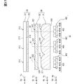
- FIG. 2 is an enlarged cross-sectional view taken along the line VI-VI of FIG. It is an enlarged sectional view of FIG.
- FIG. 2 is a view taken along the line VIII-VIII of FIG. It is a schematic diagram for demonstrating the illumination example of the image formation panel of FIG.
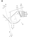
- the virtual image display device of the first embodiment is configured to be mounted on the vehicle 1 and is housed in the instrument panel 2 of the vehicle 1 as a head-up display (hereinafter referred to as HUD). It is 100.
- the vehicle 1 is broadly understood to include, for example, various vehicles such as automobiles, railroad vehicles, aircraft, ships, and non-moving game housings.
- the vehicle 1 of the present embodiment is a four-wheeled vehicle.
- the front, rear, up, down, left, and right directions of the HUD 100 are defined with reference to the vehicle 1 on the horizontal plane.
- the HUD 100 projects the display light of the image toward the windshield 3 of the vehicle 1. As a result, the display light reflected by the windshield 3 reaches the visual recognition area EB set in the interior of the vehicle 1. The occupant whose eye point EP is located in the visible area EB in the interior of the vehicle 1 perceives the display light that has reached the visible area EB as a virtual image VRI. In this way, the HUD 100 can make the viewer 4 recognize various information by displaying the virtual image VRI that can be seen by the viewer (hereinafter, simply referred to as the viewer) 4 who is the occupant of the vehicle 1. ..
- Various information displayed as a virtual image VRI by the HUD 100 include, for example, information indicating the state of the vehicle 1 such as vehicle speed and remaining fuel amount, visibility assistance information, road information, navigation information, and the like.
- the viewing area EB is a spatial area that can be visually recognized by the viewer 4 when the virtual image VRI displayed by the HUD 100 satisfies a predetermined specification (for example, the entire virtual image VRI has a predetermined brightness or higher). Also called a box.
- the visible area EB is typically set so as to overlap the irips set in the vehicle 1.
- the eye lip is set in a virtual ellipsoid shape based on the eye range that statistically represents the spatial distribution of the eye point EP in the viewer 4.
- the windshield 3 is a translucent member formed in the shape of a translucent plate by, for example, glass or synthetic resin.
- the windshield 3 is located above the instrument panel 2 and divides the interior and exterior of the vehicle 1.
- the windshield 3 is inclined so as to be separated from the instrument panel 2 from the front to the rear.
- the rear surface of the windshield 3 on the indoor side has a reflective surface 3a on which display light is projected and reflected from the HUD 100, which is formed into a smooth concave surface or a flat surface.
- the windshield 3 may be configured to utilize diffracted reflection with interference fringes instead of surface reflection by providing a reflective holographic optical element. Further, instead of the windshield 3, a combiner as a translucent member may be installed in the interior of the vehicle 1, so that the combiner may be provided with the reflecting surface 3a.
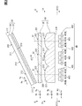
- the HUD 100 includes a light guide unit 10, an image forming unit 20, a light collecting unit 30, and a lighting unit 40.
- the light guide unit 10 constitutes an optical path L from the image forming unit 20 to the windshield 3.
- the light guide unit 10 guides the display light projected from the image forming unit 20 toward the windshield 3. It is preferable that the light guide unit 10 has a magnifying action of magnifying the image formed by the image forming unit 20 to a predetermined optical magnification to the virtual image VRI visually recognized by the viewer 4. This is because the light guide unit 10 can be miniaturized by the expanding action.
- the light guide unit 10 having such a function includes at least one optical member 11.
- the light guide unit 10 is configured by combining a plane mirror (or curved mirror) 11a and a concave mirror 11b as an optical member 11 one by one.
- the concave mirror 11b gives the above-mentioned magnifying action.
- the light guide unit 10 may be configured by combining a convex mirror and a concave mirror as the optical member 11 one by one, or may be configured by one concave mirror as the optical member 11. good.
- the optical member 11 constituting such a light guide unit 10 may be either a fixed type or a movable type.
- the image forming unit 20 forms an image that can be imaged as a virtual image VRI outside the vehicle 1, and emits the display light of the formed image toward the light guide unit 10. As shown in FIGS. 1 and 2, the image forming unit 20 includes an image display panel 21 and a diffusion panel 22.
- the image display panel 21 is formed in a plate shape as a whole.
- the image display panel 21 is a transmissive TFT liquid crystal panel using a thin film transistor.
- the image display panel 21 is an active matrix type having a plurality of liquid crystal pixels arranged two-dimensionally. Illumination light from the illumination unit 40 is incident on the incident surface 210, which is one side of the image display panel 21, through the condensing unit 30. From the emission surface 211 on the opposite side of the image display panel 21, the display light of the image is emitted toward the light guide unit 10 on the optical path L.
- the image display panel 21 displays and forms an image that serves as the display light.
- each polarizing element has a transmission axis and a blocking axis orthogonal to each other along both sides 210 and 211 of the image display panel 21.
- Each substituent transmits polarized light at the azimuth angle of the transmission axis and absorbs polarized light at the azimuth angle of the blocking axis.
- the liquid crystal layer is configured to be able to adjust the polarization of the illumination light transmitted according to the applied voltage of each liquid crystal pixel.
- the ratio of light transmitted through the polarizing element on the emission side, that is, the transmittance is adjusted for each liquid crystal pixel, so that an image is formed.
- a color filter can be provided on each liquid crystal pixel to form a color image.
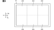
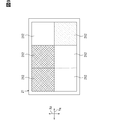
- a plurality of pixel regions 212 are set in the image display panel 21 so as to be two-dimensionally arranged by a predetermined number in the Xa direction and the Ya direction orthogonal to each other.
- Each pixel region 212 is defined as a rectangular image forming region in which a plurality of liquid crystal pixels are arranged two-dimensionally in the Xa direction and the Ya direction.
- the number of arrangements of the pixel region 212 in the Xa direction may be smaller, larger, or the same as the number of arrangements of the pixel region 212 in the Ya direction (example of FIG. 3).
- the diffusion panel 22 is formed as a whole from a hard transparent material such as glass or resin into a plate shape or a thin film shape.
- the diffusion panel 22 is arranged substantially parallel to the incident surface 210 of the image display panel 21.
- the diffusion panel 22 exerts a diffusion effect on the illumination light incident on the image display panel 21.
- the diffusion panel 22 may be integrally configured with the panel 21 by giving the incident surface 210 of the image display panel 21 minute irregularities.
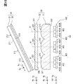
- the light collecting unit 30 shown in FIGS. 1 and 2 collects the illumination light from the lighting unit 40 toward the image forming unit 20.
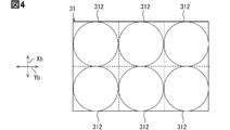
- the light collecting unit 30 includes a front lens array 31 and a rear lens array 32.
- the front lens array 31 is formed in a plate shape as a whole from a hard transparent material such as glass or resin.
- the front lens array 31 is a plano-convex lens array.
- the front lens array 31 has a plurality of front lens portions 312 that are two-dimensionally arranged in a predetermined number in the Xb direction and the Yb direction that are orthogonal to each other.
- the number of arrangements of the front lens unit 312 in the Xb direction coincides with the number of arrangements of the pixel region 212 in the Xa direction.
- the number of arrangements of the front lens unit 312 in the Yb direction coincides with the number of arrangements of the pixel region 212 in the Ya direction.
- each front lens unit 312 is associated with any of the pixel regions 212 in a 1: 1 ratio.
- Illumination light from the lighting unit 40 is incident on the front-stage incident surface 310, which is one side of each front-stage lens unit 312 shown in FIG. Illumination light incident on the front-stage incident surface 310 is emitted toward the rear-stage lens array 32 from the front-stage injection surface 311 which is the opposite surface of each front-stage lens unit 312.
- each front-stage lens unit 312 exhibits a planar shape substantially perpendicular to the optical axis Al orthogonal to the Xb direction and the Yb direction.
- the front injection surface 311 of each front lens unit 312 has a convex shape that is smoothly curved in any direction including the Xb direction and the Yb direction.
- Each front-stage lens unit 312 exerts a condensing action on the illumination light emitted toward the rear-stage lens array 32 by the convex front-stage injection surface 311.
- the function Z representing the convex shape of the front-stage injection surface 311 is given by, for example, the following equation 1.
- r is a radius (that is, a radius) from the optical axis Al with respect to an arbitrary point on a convex surface.
- c is the curvature given in a convex shape.
- k is a conic constant.
- ⁇ i is a free-form surface coefficient.
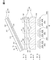
- the rear lens array 32 is formed in a plate shape as a whole from a hard transparent material such as glass or resin. As shown in FIGS. 2 and 5, the rear lens array 32 has a plurality of rear lens portions 322 that are two-dimensionally arranged by a predetermined number in the Xc direction and the Yc direction that are orthogonal to each other. The number of arrangements of the rear-stage lens unit 322 in the Xc direction matches the number of arrangements of the pixel region 212 in the Xa direction and the number of arrangements of the front-stage lens unit 312 in the Xb direction.
- each rear lens unit 322 in the Yc direction matches the number of arrangements of the pixel region 212 in the Ya direction and the number of arrangements of the front-stage lens unit 312 in the Yb direction. With these configurations, each rear lens unit 322 is associated with any of the pixel regions 212 and any of the front lens units 312 in a 1: 1 ratio.
- Each rear lens unit 322 is located in the rear stage with respect to the corresponding front lens unit 312 and has an optical axis Al in common.
- the image display panel 21 and the diffusion panel 22 are tilted with respect to the optical axis Al of each of the front lens portions 312 and each of the rear lens portions 322. Due to this tilting arrangement, the Xa direction of the image display panel 21 is defined to be tilted toward the lens arrays 31 and 32 with respect to the Xb direction of the front lens array 31 and the Xc direction of the rear lens array 32.
- the Ya direction of the image display panel 21 is defined to be substantially parallel along the Yb direction of the front lens array 31 and the Yc direction of the rear lens array 32.
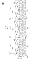
- Illumination light from the corresponding front lens unit 312 is incident on the rear incident surface 320, which is one side of each rear lens unit 322 shown in FIGS. 6 and 7. Illumination light incident on the rear-stage incident surface 320 is emitted toward the corresponding pixel region 212 from the rear-stage injection surface 321 which is the opposite surface of each rear-stage lens unit 322.
- the rear incident surface 320 forms a composite surface structure in which the forward refraction surface portion 323 and the reverse refraction surface portion 324 are alternately arranged from the optical axis Al toward the outside in the Xc direction.
- the plurality of forward refracting surface portions 323 are formed in a striped shape (see FIG. 5) that is separated from each other in the Xc direction and extends along the Yc direction.
- Each forward refraction surface portion 323 corresponds to any of the divided portions obtained by dividing the virtual base surface Si1 with a constant width in the Xc direction.
- the virtual base surface Si1 is defined to be convex on the incident side, for example, a convex surface.
- the plurality of reverse refracting surface portions 324 are formed in a striped shape (see FIG. 5) that is separated from each other in the Xc direction and extends in the Yc direction.
- Each reverse refraction surface portion 324 corresponds to any of the divided portions in which the virtual base surface Si2 is divided into a plurality of parts in the Xc direction.
- the virtual base surface Si2 is defined as having a concave shape on the injection side, for example, a valley-shaped slope.
- each forward refraction surface portion 323 collects the illumination light on the optical axis Al side in the Xc direction by refraction and collimates it with the optical axis Al, while each reverse refraction surface portion 324 refracts the illumination light in each forward refraction. It is refracted in the direction opposite to that of the surface portion 323 and mixed with the parallelized light.
- parallelization means that the illumination light is in a state of approaching the parallel luminous flux, and the illumination light does not have to be a completely parallel luminous flux.
- the rear injection surface 321 forms a composite surface structure in which the forward refraction surface portion 325 and the reverse refraction surface portion 326 are alternately arranged from the optical axis Al toward the outside in the Yc direction.
- the plurality of forward refracting surface portions 325 are formed in a striped shape (see FIG. 5) that is separated from each other in the Yc direction and extends along the Xc direction.
- Each forward refraction surface portion 325 corresponds to any of the divided portions in which the virtual base surface So1 is divided into a plurality of parts in the Yc direction.
- the virtual base surface So1 is defined to be convex to the injection side, for example, a convex surface.
- the plurality of reverse refracting surface portions 326 are formed in a striped shape (see FIG. 5) that is separated from each other in the Yc direction and extends in the Xc direction.
- Each reverse refraction surface portion 326 corresponds to any of the divided portions obtained by dividing the virtual base surface So2 with a constant width in the Yc direction.
- the virtual base surface So2 is defined as having a concave shape on the incident side, for example, a valley-shaped slope.
- each forward refraction surface portion 325 collects the illumination light on the optical axis Al side in the Yc direction by refraction and collimates it with the optical axis Al, while each reverse refraction surface portion 324 refracts the illumination light in each forward refraction. It is refracted in the direction opposite to that of the surface portion 323 and mixed with the parallelized light.
- the condensing unit 30 individually condenses the illumination light incident on each of the pixel regions 212 by the joint operation of the front lens unit 312 and the rear lens unit 322 corresponding to each pixel region 212. It is.
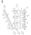
- the lighting unit 40 shown in FIGS. 1 and 2 emits illumination light that illuminates the image forming unit 20 through the condensing unit 30.
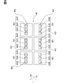
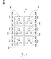
- the lighting unit 40 has a plurality of light source units 402 that are two-dimensionally arranged in a predetermined number in the Xd direction and the Yd direction that are orthogonal to each other.
- the number of arrangements of the light source unit 402 in the Xd direction matches the number of arrangements of the pixel region 212 in the Xa direction, the number of arrangements of the front stage lens unit 312 in the Xb direction, and the number of arrangements of the rear stage lens unit 322 in the Xc direction.
- each light source unit 402 in the Yd direction matches the number of arrangements of the pixel region 212 in the Ya direction, the number of arrangements of the front stage lens unit 312 in the Yb direction, and the number of arrangements of the rear stage lens unit 322 in the Yc direction.
- each light source unit 402 is associated with any of the pixel regions 212, any of the front lens units 312, and any of the rear lens units 322 in a 1: 1 ratio.
- each light source unit 402 is composed of a light source group 403 having the same configuration as each other.
- the light source group 403 of each light source unit 402 is defined by a set of light source elements 403R, 403G, and 403B that independently emit illumination light of the three primary colors of red, green, and blue (RGB).
- the light source elements 403R, 403G, and 403B of the three primary colors forming the light source group 403 are configured by individual LED bare chips and are packaged in common with each other.
- each light source unit 402 the light source elements 403R, 403G, and 403B of the three primary colors of RGB are arranged one-dimensionally side by side along the Yd direction as the linear direction.
- the Yd direction in which the light source elements 403R, 403G, and 403B are arranged in a straight line corresponds to the vertical direction Dv (see FIG. 1) of the virtual image VRI.
- the light source element of one primary color located in the center in the Yd direction (FIG. 2 is an example of 403G) is on the common optical axis Al of the corresponding front lens unit 312 and the rear lens unit 322. Is placed in.
- the light source elements 403R, 403G, and 403B are arranged closer to the condensing unit 30 than the combined focal point of the lens units 312 and 322 in the direction along the optical axis Al of the corresponding front lens unit 312 and the rear lens unit 322. Has been done.
- the intensity peak direction at which the emission intensity of the light source elements 403R, 403G, and 403B is maximized is substantially parallel along the optical axis Al of the corresponding front lens unit 312 and the rear lens unit 322.
- the Xd direction of the lighting unit 40 is defined to be substantially parallel along the Xb direction of the front lens array 31 and the Xc direction of the rear lens array 32, and is inclined with respect to the Xa direction of the image display panel 21.
- the Yd direction of the illumination unit 40 is defined to be substantially parallel along the Ya direction of the image display panel 21, the Yb direction of the front lens array 31, and the Yc direction of the rear lens array 32.
- the illumination light emitted from the light source element of at least one primary color among the light source elements 403R, 403G, and 403B of the three primary colors is sequentially incident on the corresponding front lens unit 312 and the rear lens unit 322. do. That is, the illumination unit 40 emits illumination light sequentially incident on each of the corresponding sets of the lens units 312 and 322 from the light source group 403 of the light source unit 402 individually corresponding to each of the lens units 312 and 322. .
- the pixel region 212 corresponding to the light source unit 402 in which the light source elements 403R, 403G, and 403B of the three primary colors all emit light in the light source group 403 is illuminated by the white light mixed with the three primary colors. ..
- the pixel area 212 corresponding to the light source unit 402 that emits light from the light source elements of the two primary colors and turns off the light source element of the one primary color is , Illuminated by the mixed color light of the two primary colors.
- the pixel area 212 corresponding to the light source unit 402 that emits light from the light source element of the first primary color and turns off the light source element of the second primary color is , Illuminated by the monochromatic light of the one primary color.
- a plurality of front lens units 312 are arranged so as to individually condense the illumination light incident on each of the plurality of arranged pixel regions 212 in the image forming unit 20.
- a plurality of light source units 402 are arranged so that the illumination light incident on each front lens unit 312 is emitted from the individual light source group 403.
- all of the light source elements 403R, 403G, and 403B that independently emit the illumination light of the three primary colors are arranged as close as possible to the optical axis Al of the incident destination lens unit 312. be able to.
- each pixel region 212 It is difficult to cause color unevenness and color shift in each case. Further, in the light source group 403 of each light source unit 402, the illumination light from the light source element of at least one primary color is collected by the incident destination lens unit 312 and emitted as display light from the incident destination pixel region 212, in each pixel region. It is difficult to cause color unevenness and color shift between 212.
- the chromaticity of the display light emitted from the incident destination pixel region 212 becomes vivid in the illumination light from the light source element of one primary color. From these things, it is possible to improve the visibility of the virtual image VRI.
- the light source elements 403R, 403G, and 403B of the three primary colors are arranged side by side in the Yd direction as the linear direction.
- the light source elements 403R, 403G, and 403B of the three primary colors are arranged one-dimensionally so as to be as close as possible to the optical axis Al of the incident destination lens unit 312 in the Yd direction in which they are aligned with each other. can do. Therefore, it is possible to suppress color unevenness and color shift of the display light for each pixel region 212 and between the pixel regions 212, and improve the visibility of the virtual image VRI.
- each front stage lens unit 312 a plurality of rear stage lens units 322 are provided so as to individually condense the illumination light incident on each pixel region 212 together with the front stage lens unit 312. Be arranged. Therefore, in each rear lens unit 322, the forward refracting surface portion 325 that parallelizes the illumination light by refraction and the reverse refracting surface portion 326 that refracts the illumination light and mixes it with the parallelized light alternate in the Yd direction as the linear direction. Is formed in.
- the illumination light from the light source elements of at least two primary colors not only has a condensing action in the front stage lens unit 312 but also a rear stage lens accompanied by mixing with parallelized light. Due to the light-collecting action of the unit 322, the colors are easily mixed in the Yd direction in which the elements are lined up. Therefore, it is possible to improve the visibility of the virtual image VRI by suppressing color unevenness and color shift of the display light especially in each pixel region 212.
- the Yd direction as the linear direction in which the light source elements 403R, 403G, and 403B of the three primary colors are lined up in the light source group 403 of each light source unit 402 corresponds to the vertical direction Dv of the virtual image VRI.
- the vertical direction Dv where the eyeball of the viewer 4 who visually recognizes the virtual image VRI is difficult to move the color shift of the display light in each of the pixel regions 212 where the colors are mixed is unlikely to occur due to the movement.
- the Xd direction corresponding to the left-right direction Dh see FIG.
- the light source elements 403R, 403G, and 403B of the three primary colors are used for each light source group 403 of each light source unit 402. Not lined up. Therefore, the display light in each of the pixel regions 212 to be mixed is unlikely to cause color deviation due to the movement of the eyeball of the viewer 4. From these facts, it is possible to guarantee the reliability of the effect of enhancing the visibility of the virtual image VRI.
- the light source elements 403R, 403G, and 403B of the three primary colors are packaged in common with each other.
- the light source elements 403R, 403G, and 403B of the three primary colors can be arranged together with the common packaging at positions as close as possible to the optical axis Al of the incident destination lens unit 312. can. Therefore, it is possible to improve the productivity of the HUD 100, which is a virtual image display device for enhancing the visibility of the virtual image VRI.
- the second embodiment is a modification of the first embodiment.
- the light source elements 403R, 403G, and 403B of the three primary colors forming the light source group 2403 are each composed of individual LED bare chips, and are individually packaged with each other.
- the light source elements 403R, 403G, and 403B of the three primary colors are packaged independently of each other in the light source group 2403 of each light source unit 2402.
- the position of the independent packaging as close as possible to the optical axis Al of the incident destination lens unit 312 is set as the position where the light source elements 403R, 403G, and 403B of the three primary colors are arranged.
- the third embodiment is a modification of the first embodiment.
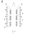
- the light source elements 403R, 403G, and 403B of the three primary colors forming the light source group 3403 in each light source unit 3402 of the third embodiment are mutually in at least one of the Yd direction which is a linear direction and the Xd direction which is an orthogonal direction thereof. They are offset and arranged in two dimensions.
- FIGS. 11 and 12 show that the light source elements of the two primary colors (examples of 403R and 403G in the same figure) are displaced only in the Xd direction, and the light source elements of the remaining one primary color (the same) with respect to the light source elements of the two primary colors.
- the figure shows an example in which the example of 403B) is arranged so as to be offset in both the Xd and Yd directions.
- the Yd direction in which the light source elements of the two primary colors are arranged so as to be offset from each other corresponds to the vertical direction Dv of the virtual image VRI (see FIG. 1 of the first embodiment).
- the center of gravity is the common optical axis of the corresponding front lens portion 312 and the rear lens portion 322. It is arranged on Al (see FIG. 11).
- the light source elements of the two primary colors are displaced only in the Yd direction, and the light source elements of the two primary colors are displaced from each other.
- the remaining one primary color light source element (the figure is an example of 403B) may be arranged so as to be offset in both the Xd and Yd directions.
- the light source elements 403R, 403G, and 403B are packaged in common with each other as in the first embodiment, but are packaged independently from each other according to the second embodiment. May be.
- the light source elements 403R, 403G, and 403B of the three primary colors have at least one of the Yd direction which is a linear direction and the Xd direction which is an orthogonal direction thereof. They are placed offset from each other on one side.
- the light source elements 403R, 403G, and 403B of the three primary colors are two-dimensionally arranged so as to be as close as possible to the optical axis Al of the incident destination lens unit 312 in a direction deviating from each other. can do. Therefore, it is possible to suppress color unevenness and color shift of the display light for each pixel region 212 and between the pixel regions 212, and improve the visibility of the virtual image VRI.
- the rear lens array 32 may not be provided.
- at least one of the rear-stage incident surface 320 and the rear-stage injection surface 321 of the rear-stage lens array 32 may be configured by the Fresnel lens surface.
- the front lens array 31 may be a TIR lens array.
- the image display panel 21 and the diffusion panel 22 may be arranged substantially perpendicular to the optical axis Al of each front lens unit 312 and each rear lens unit 322.
- the pixel regions 212 may be arranged one-dimensionally in a row in either the Xa direction or the Ya direction.
- the front-stage lens portions 312 may be arranged one-dimensionally in a row in one of the Xb direction and the Yb direction.
- the rear lens array 32 of the modified example the rear lens portions 322 may be arranged one-dimensionally in a row in one of the Xc direction and the Yc direction.
- the light source units 402 may be arranged one-dimensionally in a row in either the Xd direction or the Yd direction.
- the Xa direction and the Ya direction in the image display panel 21 of the modified example may be interchanged with each other.
- the Xc direction and the Yc direction in the rear lens array 32 of the modified example may be interchanged with each other.
- the Yd direction in each of the light source units 402, 2402, and 3402 of the modified example may correspond to the left-right direction Dh of the virtual image VRI (see FIG. 1 of the first embodiment).
Landscapes
- Engineering & Computer Science (AREA)
- Chemical & Material Sciences (AREA)
- Combustion & Propulsion (AREA)
- Transportation (AREA)
- Mechanical Engineering (AREA)
- Physics & Mathematics (AREA)
- General Physics & Mathematics (AREA)
- Optics & Photonics (AREA)
- Nonlinear Science (AREA)
- Mathematical Physics (AREA)
- Crystallography & Structural Chemistry (AREA)
- Instrument Panels (AREA)
Applications Claiming Priority (2)
| Application Number | Priority Date | Filing Date | Title |
|---|---|---|---|
| JP2020112508A JP7318597B2 (ja) | 2020-06-30 | 2020-06-30 | 虚像表示装置 |
| JP2020-112508 | 2020-06-30 |
Publications (1)
| Publication Number | Publication Date |
|---|---|
| WO2022004223A1 true WO2022004223A1 (ja) | 2022-01-06 |
Family
ID=79315920
Family Applications (1)
| Application Number | Title | Priority Date | Filing Date |
|---|---|---|---|
| PCT/JP2021/020560 Ceased WO2022004223A1 (ja) | 2020-06-30 | 2021-05-28 | 虚像表示装置 |
Country Status (2)
| Country | Link |
|---|---|
| JP (1) | JP7318597B2 (enExample) |
| WO (1) | WO2022004223A1 (enExample) |
Cited By (2)
| Publication number | Priority date | Publication date | Assignee | Title |
|---|---|---|---|---|
| EP4451041A1 (en) * | 2023-04-18 | 2024-10-23 | Continental Automotive Technologies GmbH | Head-up display unit |
| WO2025059810A1 (zh) * | 2023-09-18 | 2025-03-27 | 高创(苏州)电子有限公司 | 显示模组和投影设备 |
Citations (4)
| Publication number | Priority date | Publication date | Assignee | Title |
|---|---|---|---|---|
| JP2006500753A (ja) * | 2002-09-27 | 2006-01-05 | シーメンス アクチエンゲゼルシヤフト | 画像発生のための装置 |
| KR20080043077A (ko) * | 2006-11-13 | 2008-05-16 | 엘지전자 주식회사 | 백라이트 유닛 및 이를 포함하는 마이크로 디스플레이 장치 |
| JP2017215571A (ja) * | 2016-05-25 | 2017-12-07 | 株式会社デンソー | ヘッドアップディスプレイ装置及び画像投射ユニット |
| JP2019164285A (ja) * | 2018-03-20 | 2019-09-26 | パナソニックIpマネジメント株式会社 | ヘッドアップディスプレイ及び移動体 |
-
2020
- 2020-06-30 JP JP2020112508A patent/JP7318597B2/ja active Active
-
2021
- 2021-05-28 WO PCT/JP2021/020560 patent/WO2022004223A1/ja not_active Ceased
Patent Citations (4)
| Publication number | Priority date | Publication date | Assignee | Title |
|---|---|---|---|---|
| JP2006500753A (ja) * | 2002-09-27 | 2006-01-05 | シーメンス アクチエンゲゼルシヤフト | 画像発生のための装置 |
| KR20080043077A (ko) * | 2006-11-13 | 2008-05-16 | 엘지전자 주식회사 | 백라이트 유닛 및 이를 포함하는 마이크로 디스플레이 장치 |
| JP2017215571A (ja) * | 2016-05-25 | 2017-12-07 | 株式会社デンソー | ヘッドアップディスプレイ装置及び画像投射ユニット |
| JP2019164285A (ja) * | 2018-03-20 | 2019-09-26 | パナソニックIpマネジメント株式会社 | ヘッドアップディスプレイ及び移動体 |
Cited By (3)
| Publication number | Priority date | Publication date | Assignee | Title |
|---|---|---|---|---|
| EP4451041A1 (en) * | 2023-04-18 | 2024-10-23 | Continental Automotive Technologies GmbH | Head-up display unit |
| WO2024218008A1 (en) | 2023-04-18 | 2024-10-24 | Continental Automotive Technologies GmbH | Head-up display unit |
| WO2025059810A1 (zh) * | 2023-09-18 | 2025-03-27 | 高创(苏州)电子有限公司 | 显示模组和投影设备 |
Also Published As
| Publication number | Publication date |
|---|---|
| JP2022011390A (ja) | 2022-01-17 |
| JP7318597B2 (ja) | 2023-08-01 |
Similar Documents
| Publication | Publication Date | Title |
|---|---|---|
| JP6579212B2 (ja) | ヘッドアップディスプレイ装置 | |
| JP6319355B2 (ja) | ヘッドアップディスプレイ装置 | |
| CN109154721B (zh) | 平视显示器装置以及图像投影单元 | |
| CN108885345B (zh) | 平视显示器装置 | |
| JP7172840B2 (ja) | 虚像表示装置 | |
| JP6354667B2 (ja) | ヘッドアップディスプレイ装置 | |
| WO2022004223A1 (ja) | 虚像表示装置 | |
| WO2022130823A1 (ja) | 虚像表示装置 | |
| WO2017130481A1 (ja) | ヘッドアップディスプレイ装置及びその生産方法 | |
| CN115917399B (zh) | 虚拟图像显示装置 | |
| JP6984619B2 (ja) | 虚像表示装置 | |
| WO2017145557A1 (ja) | ヘッドアップディスプレイ装置 | |
| JP7314873B2 (ja) | 虚像表示装置 | |
| WO2017145558A1 (ja) | ヘッドアップディスプレイ装置 | |
| CN115210629B (zh) | 虚像显示装置 | |
| JP2020126101A (ja) | ヘッドアップディスプレイ用照明ユニット |
Legal Events
| Date | Code | Title | Description |
|---|---|---|---|
| 121 | Ep: the epo has been informed by wipo that ep was designated in this application |
Ref document number: 21833776 Country of ref document: EP Kind code of ref document: A1 |
|
| NENP | Non-entry into the national phase |
Ref country code: DE |
|
| 122 | Ep: pct application non-entry in european phase |
Ref document number: 21833776 Country of ref document: EP Kind code of ref document: A1 |