WO2022004129A1 - ポンプ装置 - Google Patents
ポンプ装置 Download PDFInfo
- Publication number
- WO2022004129A1 WO2022004129A1 PCT/JP2021/017642 JP2021017642W WO2022004129A1 WO 2022004129 A1 WO2022004129 A1 WO 2022004129A1 JP 2021017642 W JP2021017642 W JP 2021017642W WO 2022004129 A1 WO2022004129 A1 WO 2022004129A1
- Authority
- WO
- WIPO (PCT)
- Prior art keywords
- liquid
- air
- chamber
- pump
- pump device
- Prior art date
- Legal status (The legal status is an assumption and is not a legal conclusion. Google has not performed a legal analysis and makes no representation as to the accuracy of the status listed.)
- Ceased
Links
Images






Classifications
-
- B—PERFORMING OPERATIONS; TRANSPORTING
- B05—SPRAYING OR ATOMISING IN GENERAL; APPLYING FLUENT MATERIALS TO SURFACES, IN GENERAL
- B05B—SPRAYING APPARATUS; ATOMISING APPARATUS; NOZZLES
- B05B11/00—Single-unit hand-held apparatus in which flow of contents is produced by the muscular force of the operator at the moment of use
- B05B11/01—Single-unit hand-held apparatus in which flow of contents is produced by the muscular force of the operator at the moment of use characterised by the means producing the flow
- B05B11/10—Pump arrangements for transferring the contents from the container to a pump chamber by a sucking effect and forcing the contents out through the dispensing nozzle
- B05B11/1087—Combination of liquid and air pumps
-
- B—PERFORMING OPERATIONS; TRANSPORTING
- B05—SPRAYING OR ATOMISING IN GENERAL; APPLYING FLUENT MATERIALS TO SURFACES, IN GENERAL
- B05B—SPRAYING APPARATUS; ATOMISING APPARATUS; NOZZLES
- B05B11/00—Single-unit hand-held apparatus in which flow of contents is produced by the muscular force of the operator at the moment of use
- B05B11/01—Single-unit hand-held apparatus in which flow of contents is produced by the muscular force of the operator at the moment of use characterised by the means producing the flow
- B05B11/10—Pump arrangements for transferring the contents from the container to a pump chamber by a sucking effect and forcing the contents out through the dispensing nozzle
- B05B11/1028—Pumps having a pumping chamber with a deformable wall
- B05B11/1032—Pumps having a pumping chamber with a deformable wall actuated without substantial movement of the nozzle in the direction of the pressure stroke
-
- B—PERFORMING OPERATIONS; TRANSPORTING
- B05—SPRAYING OR ATOMISING IN GENERAL; APPLYING FLUENT MATERIALS TO SURFACES, IN GENERAL
- B05B—SPRAYING APPARATUS; ATOMISING APPARATUS; NOZZLES
- B05B11/00—Single-unit hand-held apparatus in which flow of contents is produced by the muscular force of the operator at the moment of use
- B05B11/01—Single-unit hand-held apparatus in which flow of contents is produced by the muscular force of the operator at the moment of use characterised by the means producing the flow
- B05B11/10—Pump arrangements for transferring the contents from the container to a pump chamber by a sucking effect and forcing the contents out through the dispensing nozzle
- B05B11/1042—Components or details
- B05B11/1043—Sealing or attachment arrangements between pump and container
- B05B11/1045—Sealing or attachment arrangements between pump and container the pump being preassembled as an independent unit before being mounted on the container
-
- B—PERFORMING OPERATIONS; TRANSPORTING
- B05—SPRAYING OR ATOMISING IN GENERAL; APPLYING FLUENT MATERIALS TO SURFACES, IN GENERAL
- B05B—SPRAYING APPARATUS; ATOMISING APPARATUS; NOZZLES
- B05B7/00—Spraying apparatus for discharge of liquids or other fluent materials from two or more sources, e.g. of liquid and air, of powder and gas
- B05B7/0018—Spraying apparatus for discharge of liquids or other fluent materials from two or more sources, e.g. of liquid and air, of powder and gas with devices for making foam
- B05B7/0025—Spraying apparatus for discharge of liquids or other fluent materials from two or more sources, e.g. of liquid and air, of powder and gas with devices for making foam with a compressed gas supply
- B05B7/0031—Spraying apparatus for discharge of liquids or other fluent materials from two or more sources, e.g. of liquid and air, of powder and gas with devices for making foam with a compressed gas supply with disturbing means promoting mixing, e.g. balls, crowns
- B05B7/0037—Spraying apparatus for discharge of liquids or other fluent materials from two or more sources, e.g. of liquid and air, of powder and gas with devices for making foam with a compressed gas supply with disturbing means promoting mixing, e.g. balls, crowns including sieves, porous members or the like
Definitions
- the present invention relates to a pump device.
- foam discharge containers that store liquids such as hand soap, facial cleansers, body soap, and hair styling products have become widespread.
- the foam discharge container mixes the contained liquid and air to generate bubbles, and discharges the generated bubbles.
- Patent Document 1 discloses a foam discharge container including a piston dome including a liquid piston portion and an elastically deformable dome.
- the dome When the dome is pushed in the foam discharge container, the volume of the air chamber that holds the air decreases, so that air flows from the air chamber into the mixing zone, and the liquid piston part is pushed into the liquid chamber to mix from the liquid chamber. Liquid matter flows into the zone.
- the present invention relates to a pump device capable of easily adjusting the amount of bubbles, the gas-liquid ratio, and the like.
- one aspect of the present invention is to mix the liquid material stored in the liquid pump chamber and the air stored in the air pump chamber to generate bubbles, and to generate the bubbles from the discharge port.
- a pump device capable of discharging, a liquid chamber main body having a recess, an elastically deformable liquid chamber lid portion that covers the liquid chamber opening that is an opening of the recess and forms the liquid pump chamber together with the recess.
- An air chamber main body having an air chamber opening that opens in the same direction as the liquid chamber opening, and an elastically deformable air chamber lid portion that covers the air chamber opening and forms the air pump chamber together with the air chamber main body.
- the present invention relates to a pump device provided with a pressing portion for pressing the liquid chamber lid portion as the air chamber lid portion is elastically deformed.
- the pump device of the present invention it is possible to easily adjust the amount of bubbles, the gas-liquid ratio, and the like.
- One embodiment of the present invention relates to a container for accommodating a liquid material, and more particularly to a foam discharge container that mixes a liquid material and air to generate bubbles and discharges the generated bubbles.
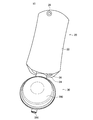
- a schematic configuration of the foam discharge container 10 according to the embodiment of the present invention will be described with reference to FIG. 1.
- FIG. 1 is an explanatory diagram showing an external configuration of a foam discharge container 10 according to an embodiment of the present invention.
- the foam discharge container 10 according to the embodiment of the present invention includes a container body 20 and a pump device 30.
- the container body 20 forms a storage space for liquid substances.
- the container body 20 is a film container having a pair of facing main films 22, a top film 24, and a bottom film (not shown). The edges of each film are joined, for example, by thermocompression bonding. As a result, a space for accommodating the liquid material surrounded by the main film 22, the top film 24 and the bottom film can be obtained.
- the liquid material sucked into the liquid pump chamber (PL), which will be described later, is stored in the storage space of the container body 20.
- PL liquid pump chamber
- the top film 24 is provided with a spout 26 that engages with the pump device 30.
- the spout 26 has a tubular shape that forms two opposing openings. The opening on one side of the spout 26 is connected to the storage space for liquid matter, and the opening on the other side is connected to the liquid pump chamber described later of the pump device 30. Therefore, the liquid material contained in the storage space of the container body 20 can flow into the liquid pump chamber of the pump device 30 via the spout 26.
- the main film 22 has a hanging hole 28.
- the hanging hole 28 is a hole through which a hanging member such as an S-shaped hook is passed.
- the liquid material contained in the container body 20 may be a liquid, a gel or a paste. Liquids, gels and pastes are all common in that they have fluidity, but liquids do not have a fixed shape and gels and pastes are semi-solid and may have a temporary shape. Specifically, the liquid material contained in the container body 20 may be a liquid detergent, a softener, a bleaching agent, a shampoo, a rinse, a conditioner, a body soap, a cosmetic liquid, a drug, a liquid seasoning or the like.
- the pump device 30 sucks a liquid substance from the container body 20, generates bubbles from the sucked liquid substance, and discharges the generated bubbles.
- the pump device 30 has an air dome 360 and a discharge port 390.
- the pump device 30 When the user presses the air dome 360, the pump device 30 generates bubbles by mixing the liquid material sucked from the container body 20 through the spout 26 with air, and discharges the generated bubbles from the discharge port 390. do.
- ⁇ Pump device configuration The schematic configuration of the foam discharge container 10 according to the embodiment of the present invention has been described above. Subsequently, with reference to FIGS. 2 to 4, the configuration of the pump device 30 according to the embodiment of the present invention will be described in detail.
- FIG. 2 is a side view of the pump device 30 according to the embodiment of the present invention.
- FIG. 3 is a plan view of the pump device 30 according to the embodiment of the present invention.
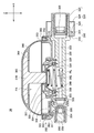
- FIG. 4 is an explanatory view showing a cross section obtained by cutting the pump device 30 along the I-I line shown in FIG.
- the pump device 30 includes a cap 310, a cylindrical portion 320, a liquid chamber main body 330, a liquid dome 340, a liquid ring 348, and an air chamber. It includes a main body 350, an air dome 360, an air ring 368, a pressing portion 370, and a mixing unit 380.
- the cap 310 has a tubular portion 314 and an overhanging portion 316.
- the tubular portion 314 is located on the outer peripheral side of the liquid chamber main body 330.
- the overhanging portion 316 projects from the end of the tubular portion 314 on the PL side of the liquid pump chamber to the liquid chamber main body 330 side.
- a screwed portion is formed on the inner peripheral surface of the tubular portion 314, and the screwed portion is screwed with the outer peripheral surface of the spout 26 of the container body 20, so that the cap 310 and the spout 26 are engaged with each other.
- the cylindrical portion 320 has an outer cylinder portion 324, an inner cylinder portion 325, and an overhanging portion 326.
- a gap is formed between the outer cylinder portion 324 and the inner cylinder portion 325 to fit the liquid chamber main body 330.
- the liquid suction valve 328 is fixed by fitting the cylindrical portion 320 to the liquid chamber main body 330.
- the overhanging portion 326 projects from the end of the outer cylinder portion 324 on the liquid pump chamber PL side to the cylinder portion 314 side of the cap 310.
- the outer peripheral diameter of the overhanging portion 326 is larger than the inner peripheral diameter of the overhanging portion 316 of the cap 310. Therefore, the overhanging portion 316 of the cap 310 abuts on the overhanging portion 326, which limits the movement of the cap 310.
- a liquid suction valve 328 is provided between the end of the inner cylinder portion 325 on the liquid pump chamber PL side and the liquid chamber main body 330.
- the liquid suction valve 328 has a cylindrical substrate and a plate-shaped valve body. The valve body is connected to the substrate at one end in the axial direction of the substrate via a connecting portion, and can be elastically displaced in the axial direction with respect to the substrate.
- the valve body of the liquid suction valve 328 moves to suck the liquid.
- the valve 328 opens, and the container body 20 and the liquid chamber body 330 communicate with each other.
- the liquid suction valve 328 closes, and the container body 20 and the liquid chamber body 330 are separated by the liquid suction valve 328. It returns to the state where it was done. While the internal pressure of the liquid chamber main body 330 exceeds the internal pressure of the container main body 20, the liquid suction valve 328 is kept closed.
- the liquid chamber main body 330 has a hole portion 332, a liquid suction path 333, a recess 334, a liquid discharge path 335, a fitting groove 336, and a liquid discharge valve 338.
- the hole portion 332 locks the claw 359a provided in the air chamber main body 350.
- the hole portion 332 engages the claw 359a provided in the air chamber main body 350, whereby the liquid chamber main body 330 and the air chamber main body 350 are connected.
- the liquid suction path 333 is an example of a first flow path for supplying a liquid substance to the recess 334.
- the liquid suction path 333 connects the container body 20 and the recess 334, and the liquid material sucked from the container body 20 flows into the recess 334 via the liquid suction path 333.
- the recess 334 forms a liquid pump chamber PL together with the liquid dome 340 by covering the liquid chamber opening which is the opening of the recess 334 with the liquid dome 340.
- the liquid material that has flowed in from the liquid suction path 333 collects in the liquid pump chamber PL.
- the liquid discharge path 335 is an example of a second flow path connecting the recess 334 and the mixing unit 380.
- the liquid suction path 333 and the liquid discharge path 335 are formed in the same direction, that is, along the front-rear direction.
- the fitting groove 336 is a groove formed so as to surround the liquid chamber opening in a plan view.
- the liquid chamber body 330 and the liquid dome 340 are connected by fitting the liquid dome 340 and the liquid ring 348 into the fitting groove 336.
- the liquid discharge valve 338 is provided between the liquid discharge path 335 and the mixing unit 380.
- the liquid discharge valve 338 has a cylindrical substrate and a plate-shaped valve body.
- the valve body is connected to the substrate at one end in the axial direction of the substrate via a connecting portion, and can be elastically displaced in the axial direction with respect to the substrate.
- the valve body of the liquid discharge valve 338 moves to discharge the liquid.
- the valve 338 opens, and the liquid chamber main body 330 and the mixing unit 380 communicate with each other.
- the liquid discharge valve 338 closes, and the liquid chamber main body 330 and the mixing unit 380 are separated by the liquid discharge valve 338. It returns to the state where it was done.
- the depth direction of the recess 334 is referred to as a vertical direction (Z-axis direction shown in FIGS. 2 and 4), and the liquid chamber opening side seen from the bottom of the recess 334 is referred to as an upper side thereof.
- the opposite side may be referred to as the lower side.
- the direction in which the liquid material moves from the liquid pump chamber PL to the mixing unit 380 that is, the direction in which the liquid discharge path 335 extends is referred to as the front-rear direction (X-axis direction shown in FIGS. 2 to 4), and the liquid pump chamber.
- the mixing unit 380 side seen from the PL may be referred to as a front side, and the opposite side may be referred to as a lower side.
- a direction orthogonal to both the vertical direction and the front-back direction may be referred to as a width direction (Y-axis direction shown in FIG. 3).
- the liquid dome 340 covers the liquid chamber opening which is the opening of the recess 334, and forms the liquid pump chamber PL together with the recess 334.
- the liquid dome 340 is an example of a liquid chamber lid, and can be elastically deformed. In the initial state before the liquid dome 340 is elastically deformed, the liquid dome 340 has a dome shape that bulges toward the opposite side of the recess 334 (bulges upward with respect to the liquid chamber opening).
- the dome shape includes, for example, a curved surface portion obtained by cutting out a part of a spherical surface. Further, the liquid dome 340 may be circular or elliptical in a plan view. As shown in FIG. 4, the liquid dome 340 is connected to the liquid chamber main body 330 by fitting the edge of the liquid dome 340 into the fitting groove 336 formed in the liquid chamber main body 330.
- a spring 342 that expands and contracts in the vertical direction is provided between the liquid dome 340 and the recess 334. Specifically, one end of the spring 342 abuts on the bottom surface of the recess 334, and the other end of the spring 342 abuts on the top surface of the liquid dome 340.
- the liquid ring 348 is a member having a ring shape. As shown in FIG. 4, the liquid ring 348 fits into the fitting groove 336 from above the edge of the liquid dome 340. As a result, the liquid dome 340 and the liquid chamber main body 330 are firmly connected.
- the air chamber main body 350 has an air chamber opening that opens in the same direction as the liquid chamber opening of the recess 334.
- the air chamber main body 350 will be described with reference to FIG. 5 in addition to FIGS. 2 to 4.
- FIG. 5 is a side view and a bottom view of the air chamber main body 350.
- the air chamber main body 350 has a base portion 351 and a connecting portion 359.
- the connecting portion 359 protrudes from the lower surface of the base portion 351 and has a tubular shape.
- a plurality of claws 359a that are separated from each other in the circumferential direction are formed.
- the claw 359a is locked to the hole portion 332 of the liquid chamber main body 330, so that the air chamber main body 350 is connected to the liquid chamber main body 330.
- the base portion 351 has an outer ring portion 352, an inner ring portion 353, an air suction port 354, an air suction valve 355, an air discharge port 356, and a tubular portion 357.
- the outer ring portion 352 is an annular region protruding upward from the outermost edge of the bottom portion of the base portion 351.
- the annular shape surrounds a certain region, and the shape may be circular, square, continuous, or intermittent. You may.
- the inner ring portion 353 is an annular region protruding from the bottom of the base portion 351 at intervals from the outer ring portion 352.
- the opening surrounded by the upper edge of the inner ring portion 353 is the air chamber opening.
- the air chamber main body 350 forms the air pump chamber PA together with the air dome 360.
- the air chamber main body 350 and the air dome 360 are connected by fitting the edge of the air dome 360 into the annular groove formed between the outer ring portion 352 and the inner ring portion 353. ,
- the air chamber opening is covered with an air dome 360.
- the air intake port 354 is an opening formed at the bottom of the base 351.
- a plurality of air intake ports 354 may be formed intermittently. For example, in the example shown in FIG. 5, four air intake ports 354 are formed on the same circumference at equal intervals. Air is sucked into the air pump chamber PA through such an air suction port 354.
- the air suction valve 355 has a ring shape and is provided between the air suction port 354 and the air pump chamber PA.
- the air suction valve 355 opens and the air pump chamber PA is opened via the air suction port 354. Air is inhaled into.
- the air suction valve 355 closes and becomes the air suction port 354.
- the air pump chamber PA is partitioned by the air suction valve 355.
- the air discharge port 356 is an opening formed at the bottom of the base 351.
- the air stored in the air pump chamber PA flows into the mixing unit 380 through the air discharge port 356.
- the tubular portion 357 has a tubular configuration in which the axial direction is the same as the vertical direction.
- the tubular portion 357 is formed so as to project from the bottom of the base portion 351 and is arranged between the liquid dome 340 and the air dome 360. More specifically, the tubular portion 357 is located between the liquid dome 340 and the air dome 360, and is located closer to the liquid dome 340 than the air dome 360.
- the tubular portion 357 forms a shaft insertion port 358 as shown in FIG.
- a pressing portion 370 shaft portion 374 is inserted into the shaft insertion port 358.
- the shape meant by the tubular shape may be a cylindrical shape, a square tubular shape, a continuous shape in the circumferential direction, or an intermittent shape. ..
- Air dome 360 As shown in FIG. 4, the air dome 360 covers the air chamber opening of the air chamber main body 350 and forms the air pump chamber PA together with the air chamber main body 350.
- the air dome 360 is an example of an air chamber lid, and can be elastically deformed. In the initial state before the air dome 360 is elastically deformed, the air dome 360 has a dome shape that bulges toward the side opposite to the air chamber main body 350 (bulges upward with respect to the air chamber opening).
- the dome shape includes, for example, a curved surface portion obtained by cutting out a part of a spherical surface. Further, the air dome 360 may be circular or elliptical in a plan view.
- the air dome 360 has an air chamber main body in which the edge of the air dome 360 is fitted into a groove formed between the outer ring portion 352 and the inner ring portion 353 of the air chamber main body 350. Connect to 350.
- the inner diameter of the air pump chamber PA is larger than the inner diameter of the liquid pump chamber PL.
- the ratio of the inner diameter of the air pump chamber PA to the inner diameter of the liquid pump chamber PL may be 2 to 3: 1, and more preferably 2.89: 1.
- Such an air dome 360 has a ceiling portion 362 and a ring region 364 overhanging inside the air dome 360 so as to face the ceiling portion 362.
- the pressing portion 370 is supported by a part of the pressing portion 370 sandwiched between the ceiling portion 362 and the ring region 364.
- the air ring 368 is a member having a ring shape. As shown in FIG. 4, the air ring 368 fits into a groove formed between the outer ring portion 352 and the inner ring portion 353 of the air chamber main body 350 from above the edge of the air dome 360. As a result, the liquid dome 340 and the liquid chamber main body 330 are firmly connected.
- the pressing portion 370 is provided between the liquid dome 340 and the air dome 360, and presses the liquid dome 340 with elastic deformation of the air dome 360.
- the pressing portion 370 is formed to be harder than the liquid dome 340 and the air dome 360.
- FIG. 6 is a plan view and a side view of the pressing portion 370.
- the pressing portion 370 has a head portion 372 and a shaft portion 374.
- the head portion 372 is a portion protruding from the upper end of the shaft portion 374 in a direction intersecting the axial direction. Therefore, the diameter of the head portion 372 is larger than the diameter of the shaft portion 374.
- FIG. 6 shows an example in which the head portion 372 and the shaft portion 374 have a circular shape in a plan view
- the shapes of the head portion 372 and the shaft portion 374 may be polygonal in a plan view. ..
- the diameter of the circle circumscribing the polygon is treated as the diameter of the head 372.
- the shape of the shaft portion 374 is a polygon in a plan view
- the diameter of the circle circumscribing the polygon is treated as the diameter of the shaft portion 374.
- the upper surface of the head 372 abuts on the inner surface of the ceiling portion 362 of the air dome 360, and the outer edge of the lower surface of the head 372 abuts on the upper surface of the ring region 364 of the air dome 360. That is, the head 372 is accommodated in the space formed between the ceiling portion 362 and the ring region 364 of the air dome 360, and is supported by the ceiling portion 362 and the ring region 364.
- the shaft portion 374 extends between the air dome 360 and the liquid dome 340, the lower end abuts on the liquid dome 340, and the upper end is connected to the head 372. As shown in FIG. 4, the shaft portion 374 is inserted into the shaft insertion port 358 formed by the tubular portion 357 and abuts on the liquid dome 340. The diameter of the shaft portion 374 is smaller than the diameter of the liquid dome 340.
- the pressing portion 370 is arranged substantially coaxially with the spring 342 in the liquid pump chamber PL.
- the mixing unit 380 is an example of a mixing unit that mixes the liquid material flowing in from the liquid pump chamber PL and the air flowing in from the air pump chamber PA to generate bubbles. As shown in FIG. 4, the mixing unit 380 has an air discharge valve 382, a mixing cylinder 384, and a mesh member 386.
- the air discharge valve 382 is provided at a position that closes the air discharge port 356 of the air chamber main body 350.
- the air discharge valve 382 has a cylindrical substrate and a plate-shaped valve body.
- the valve body is connected to the substrate at one end in the axial direction of the substrate via a connecting portion, and can be elastically displaced in the axial direction with respect to the substrate.
- the valve body of the air discharge valve 382 is released. By moving, the air discharge valve 382 opens, and the air chamber main body 350 and the mixing unit 380 communicate with each other.
- the air discharge valve 382 closes and the air chamber main body 350 and the mixing unit 380 are separated by the air discharge valve 382. It returns to the state where it was done.
- Liquid matter flows into the mixing cylinder 384 from the liquid pump chamber PL via the liquid discharge valve 338, and air flows from the air pump chamber PA through the air discharge valve 382.
- the mixing cylinder 384 mixes the inflowing liquid and air to generate bubbles.
- the mesh member 386 is a member having porosity.
- the foam generated by the mixing cylinder 384 passes through the mesh member 386 and is discharged from the discharge port 390.
- the mesh member 386 makes the bubbles generated by the mixing cylinder 384 finer as the bubbles generated by the mixing cylinder 384 pass through the mesh member 386.
- FIG. 4 shows one type of mesh member 386, a plurality of types of mesh members may be laminated along the front-rear direction.
- FIG. 7 is an explanatory diagram showing an operation in which the pump device 30 discharges bubbles.
- the volume of the air pump chamber PA decreases due to the elastic deformation of the air dome 360, and the internal pressure of the air pump chamber PA increases.
- the valve body of the air discharge valve 382 moves.
- the air discharge valve 382 opens, and the air pump chamber PA and the mixing unit 380 communicate with each other.
- the pressing portion 370 also displaces while pressing the liquid dome 340.
- the volume of the liquid pump chamber PL decreases due to the elastic deformation of the liquid dome 340, and the internal pressure of the liquid pump chamber PL increases.
- the valve body of the liquid discharge valve 338 moves.
- the liquid discharge valve 338 opens, and the liquid pump chamber PL and the mixing unit 380 communicate with each other.
- the liquid material flows into the mixing cylinder 384 from the liquid pump chamber PL.
- the mixing cylinder 384 mixes air and liquid matter to generate bubbles. Then, as shown by the thick arrow in FIG. 7, the mesh member 386 breaks the bubbles into small pieces, and the bubbles are discharged from the discharge port 390.
- the air dome 360 returns to the dome shape due to the elastic force of the air dome 360, the elastic force of the liquid dome 340, and the elastic force of the spring 342. In the process of returning the air dome 360 to the dome shape, an operation of sucking air and liquid matter is performed.
- FIG. 8 is an explanatory diagram showing an operation in which the pump device 30 sucks air and liquid matter.
- the air dome 360 returns to the dome shape, the volume of the air pump chamber PA increases and the internal pressure of the air pump chamber PA decreases.
- the air suction valve 355 opens. As a result, as shown by the broken line arrow in FIG. 8, air is sucked into the air pump chamber PA through the air suction port 354.
- the pressing of the liquid dome 340 by the pressing portion 370 is released.
- the liquid dome 340 returns to the dome shape due to the elastic force of the liquid dome 340 and the elastic force of the spring 342.
- the volume of the liquid pump chamber PL increases and the internal pressure of the liquid pump chamber PL decreases.
- the liquid suction valve 328 Opens.
- the liquid material is sucked from the container main body 20 via the liquid suction valve 328, and the liquid material flows into the liquid pump chamber PL.
- the pump device 30 according to the embodiment of the present invention described above exhibits various functions and effects. Hereinafter, the effects of the pump device 30 according to the embodiment of the present invention will be illustrated.
- the inflow of air and liquid into the mixing unit 380 is realized by deformation of the dome. Therefore, by changing the shape of the liquid dome 340, the shape of the air dome 360, the length of the shaft portion 374, etc., the deformation amount of the liquid dome 340, the deformation amount of the air dome 360, or the shaft portion 374 is the liquid dome 340.
- the amount of pressing down changes.
- the amount of air or liquid material flowing into the mixing unit 380 depends on the amount of deformation of the liquid dome 340, the amount of deformation of the air dome 360, the amount of the shaft portion 374 pushing down the liquid dome 340, and the like.
- the air pump chamber PA and the liquid pump chamber PL can be located outside the container body 20. Therefore, in one embodiment of the present invention, the diameter of the container body 20 can be made smaller than that in the case where the air pump chamber PA or the liquid pump chamber PL is provided inside the container body 20.
- the air chamber opening and the liquid chamber opening are opened in the same direction. Therefore, by one operation of pushing down the air dome 360 facing both the air chamber opening and the liquid chamber opening, the volumes of the air pump chamber PA and the liquid pump chamber PL are increased based on the action of the pressing portion 370. It can be reduced at the same time.
- the inflow of the liquid substance into the mixing unit 380 is realized by the deformation of the dome, and the diameter of the shaft portion 374 of the pressing portion 370 is smaller than the diameter of the liquid dome 340. Therefore, the pump device 30 according to the embodiment of the present invention mixes more liquid matter by pushing down the air dome 360 once, as compared with the case where the shaft portion 374 is applied to the pump device operated by the piston type. It can be supplied to the unit 380.
- the pressing portion 370 has a head portion 372 that is connected to one end of the shaft portion 374 and projects in a direction intersecting the axial direction of the shaft portion 374, and the other end of the shaft portion 374 is. It abuts on the liquid dome 340 and the head 372 abuts on the inner surface of the air dome 360. Therefore, when the user pushes the air dome 360, the head 372 is likely to receive the user's force. Therefore, the user's force can be efficiently transmitted to the shaft portion 374 and the liquid dome 340 via the head portion 372.
- the pressing portion 370 is formed to be harder than the air dome 360 and the liquid dome 340. Therefore, the pressing portion 370 can press the liquid dome 340 as the air dome 360 is pushed down without buckling due to the elastic force of the air dome 360 and the liquid dome 340.
- the air chamber main body 350 has a tubular portion 357 into which the shaft portion 374 is inserted. Therefore, since the moving direction of the shaft portion 374 is guided in the vertical direction which is the axial direction of the tubular portion 357, the pressing force of the shaft portion 374 can be efficiently applied for the deformation of the liquid dome 340. be. Further, since the tubular portion 357 is arranged closer to the liquid dome 340 than the air dome 360, the axis of the pressing portion 370 is less likely to shift with respect to the liquid dome 340, and the pressing portion 370 is efficient for the liquid dome 340. It is possible to transmit the pressing force to the dome.
- the liquid suction path 333 and the liquid discharge path 335 are formed along the same direction. Therefore, the pump device 30 according to the embodiment of the present invention can be suitably applied to the foam discharge container 10 used by suspending.
- the inflow of air and liquid into the mixing unit 380 is realized by the deformation of the dome, so that the pump device 30 according to the embodiment of the present invention is a pump device that operates in a piston type. It can be realized at a lower height than the above. Therefore, it is possible to reduce the size of the foam discharge container 10 and reduce the amount of resin, and even when the foam discharge container 10 is hung and used, a neat aesthetic feeling can be obtained.
- the spring 342 is provided in the liquid pump chamber PL.
- the liquid dome 340 can return to the dome shape based on the elastic force of the liquid dome 340 and the elastic force of the spring 342. Therefore, even when the viscosity of the liquid material contained in the container body 20 is high, the liquid material can be smoothly sucked into the liquid pump chamber PL. Further, the air dome 360 can return to the dome shape based on the elastic force of the air dome 360 and the force of the pressing portion 370 being pushed upward by the liquid dome 340.
- the elastic force for the liquid dome 340 to return to the dome shape may be sufficient with the elastic force of the liquid dome 340.
- the spring 342 may not be provided in the liquid pump chamber PL.
- a plurality of air suction ports 354 are intermittently formed at the bottom of the air chamber main body 350. According to such a configuration, it is possible to quickly suck air into the air pump chamber PA without bias. By arranging the plurality of air intake ports 354 on the same circumference, it is possible to further suppress the occurrence of bias in air intake.
- FIG. 9 is an explanatory diagram showing an external configuration of the foam discharge container 12 according to the first modification.
- the foam discharge container 12 according to the first modification includes a container body 20, a pump device 32, and a bag container holder 42.
- the bag container holder 42 has a bottom portion, a side portion, and a top surface portion, and the container body 20 is housed in a space surrounded by these portions.
- the bag container holder 42 is a synthetic resin such as PP (polypropylene), ABS (acrylonitrile / butadiene / styrene copolymer synthetic resin), acrylic, polyester, PCT (polycyclohexylene / dimethylene / terephthalate), SAN (styrene acrylonitrile copolymer). It may be an injection-molded product made of.
- a U-shaped notch 44 is formed on the top surface of the bag container holder 42.
- the open portion side of the U-shaped notch 44 is a detachable space portion for attaching / detaching the container body 20.
- the spout 26 of the container body 20 has a tubular shape forming two facing openings.
- the opening on one side of the spout 26 is connected to the storage space for the liquid material, and the opening on the other side is connected to the liquid pump chamber PL of the pump device 32.
- the pump device 32 sucks the liquid material from the container body 20, generates bubbles from the sucked liquid material, and discharges the generated bubbles.
- the internal configuration of the pump device 32 will be described with reference to FIG.
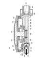
- FIG. 10 is an explanatory view showing a cross section of the pump device 32 according to the first modification.
- the pump device 32 according to the first modification includes a cap 310, a cylindrical portion 320, a liquid chamber main body 331, a liquid dome 340, a liquid ring 348, an air chamber main body 350, and the like. It includes an air dome 360, an air ring 368, a pressing portion 370, and a mixing unit 380.
- the cap 310, the cylindrical portion 320, the liquid dome 340, the liquid ring 348, the air chamber body 350, the air dome 360, the air ring 368, the pressing portion 370, and the mixing unit 380 are as described with reference to FIGS. 2 to 4. Since there is, a detailed description here will be omitted.
- the liquid chamber main body 331 has a liquid suction path 339, a recess 334, a liquid discharge path 335, a fitting groove 336, and a liquid discharge valve 338.
- the main difference between the above-described embodiment and the first modification is the direction in which the liquid suction path is formed. Specifically, in the embodiment described with reference to FIG. 4, the liquid suction path 333 is formed along the same front-rear direction as the liquid discharge path 335, whereas in the first modification, the liquid is formed.
- the suction passage 339 is formed along the vertical direction intersecting the liquid discharge passage 335.
- the liquid pump chamber PL sucks the liquid material from the container main body 40 through the liquid suction path 333 and supplies the liquid material to the mixing unit 380 as in the above-described embodiment. It is possible. In addition, it is possible to exert some or all of the effects of the above-described embodiments.
- the air dome 360 may be designed so that the air pump chamber PA has a donut shape.
- the shaft portion 374 of the pressing portion 370 may be inserted inside the inner peripheral portion of the donut shape, and the head portion 372 of the pressing portion 370 may push down the air dome 360 from the upper surface of the donut shape.
- the elastic force of the air dome 360 is improved, and air can be sucked into the air pump chamber PA more smoothly.
- the pump device 30 having the pressing portion 370 that presses the liquid dome 340 with the elastic deformation of the air dome 360 has been described, but the reverse may be performed. That is, the pressing portion 370 is provided between the air dome 360 as the air chamber lid portion and the liquid dome 340 as the liquid chamber lid portion, and presses the air dome 360 with the elastic deformation of the liquid dome 340. There may be.
- the present invention further discloses the following pump device and container.
- a pump device capable of mixing the liquid material stored in the liquid pump chamber and the air stored in the air pump chamber to generate bubbles and discharging the bubbles from the discharge port.
- the liquid chamber body with a recess and An elastically deformable liquid chamber lid that covers the liquid chamber opening that is the opening of the recess and forms the liquid pump chamber together with the recess.
- An air chamber body having an air chamber opening that opens in the same direction as the liquid chamber opening, An elastically deformable air chamber lid that covers the air chamber opening and forms the air pump chamber together with the air chamber body.
- a mixing unit that mixes the liquid material that has flowed in from the liquid pump chamber and the air that has flowed in from the air pump chamber to generate the bubbles.
- a pressing portion provided between the air chamber lid portion and the liquid chamber lid portion and pressing the liquid chamber lid portion with elastic deformation of the air chamber lid portion. Equipped with a pump device.
- ⁇ 2> The pump device according to ⁇ 1>, wherein the pressing portion has a shaft portion extending between the air chamber lid portion and the liquid chamber lid portion.
- the pressing portion has a head that is connected to one end of the shaft portion and projects in a direction intersecting the axial direction of the shaft portion, and the other end of the shaft portion abuts on the liquid chamber lid portion and the head portion is contacted.
- ⁇ 4> The pump device according to ⁇ 2> or ⁇ 3>, wherein the shaft portion is formed harder than the liquid chamber lid portion and the air chamber lid portion.
- the air chamber main body has a tubular portion into which the shaft portion is inserted, and the axial direction of the tubular portion is the same as the depth direction of the recess, any of the above ⁇ 2> to ⁇ 4>.
- the pump device according to 1. ⁇ 6> The pump device according to ⁇ 5>, wherein the tubular portion is arranged between the air chamber lid portion and the liquid chamber lid portion. ⁇ 7> The pump device according to ⁇ 6>, wherein the tubular portion is arranged at a position closer to the liquid chamber lid portion than the air chamber lid portion.
- ⁇ 8> The pump device according to any one of ⁇ 2> to ⁇ 7>, wherein the inner diameter of the liquid pump chamber is larger than the diameter of the shaft portion.
- the pump device according to any one of ⁇ 1> to ⁇ 8>, further comprising an elastic body that expands and contracts along the depth direction of the recess between the liquid chamber lid and the recess.
- Pumping device ⁇ 10> The pump device according to ⁇ 9>, wherein the elastic body is a spring.
- the pressing portion is arranged substantially coaxially with the spring.
- the pump device according to any one of ⁇ 1> to ⁇ 12>, wherein a plurality of air suction ports are intermittently formed on the bottom of the air chamber main body.
- the pump device according to ⁇ 13>, wherein the plurality of air intake ports are arranged on the same circumference.
- the liquid chamber main body has a first flow path for supplying the liquid substance to the recess, and a second flow path connecting the recess and the mixing portion, and the first flow path and the second flow path are The pump device according to any one of ⁇ 1> to ⁇ 14>, which is formed along the same direction.
- ⁇ 16> The pump device according to any one of ⁇ 1> to ⁇ 15>, wherein the liquid chamber lid portion bulges to the side opposite to the recess.
- ⁇ 17> The pump device according to any one of ⁇ 1> to ⁇ 16>, wherein the air chamber lid portion bulges to the side opposite to the air chamber main body.
- ⁇ 18> The pump device according to any one of ⁇ 1> to ⁇ 17>, which has a connecting portion for connecting the air chamber main body and the liquid chamber main body.
- ⁇ 19> The pump device according to any one of ⁇ 1> to ⁇ 18>, wherein the mixing unit has a mesh member.
- a container comprising the pump device according to any one of ⁇ 1> to ⁇ 19> and a container body for accommodating the liquid material to be sucked into the liquid pump chamber.
Landscapes
- Closures For Containers (AREA)
- Containers And Packaging Bodies Having A Special Means To Remove Contents (AREA)
Abstract
本発明は、液ポンプ室(PL)に貯留された液状物と、空気ポンプ室(PA)に貯留された空気とを混合して泡を生成し、吐出口(390)から前記泡を吐出可能なポンプ装置(30)であって、凹部(334)を有する液室本体(330)と、前記凹部(334)の開口である液室開口部を覆い、前記凹部(334)と共に前記液ポンプ室(PL)を形成する弾性変形可能な液室蓋部(340)と、前記液室開口部と同じ向きに開口する空気室開口部を有する空気室本体(350)と、前記空気室開口部を覆い、前記空気室本体(350)と共に前記空気ポンプ室(PA)を形成する弾性変形可能な空気室蓋部(360)と、前記液ポンプ室(PL)から流入した前記液状物、および前記空気ポンプ室(PA)から流入した前記空気を混合して泡を生成する混合部(380)と、前記空気室蓋部(360)と前記液室蓋部(340)の間に設けられ、前記空気室蓋部(360)の弾性変形に伴って前記液室蓋部(340)を押圧する押圧部(370)とを備え、泡の量や気液比などを容易に調整できる。
Description
本発明は、ポンプ装置に関する。
近年、ハンドソープ、洗顔料、ボディーソープ、および整髪料などの液状物を収容する泡吐出容器が広く普及している。泡吐出容器は、収容している液状物と空気を混合して泡を生成し、生成された泡を吐出する。
このような泡吐出容器に関して、特許文献1には、液ピストン部および弾性変形可能なドームからなるピストンドームを備える泡吐出容器が開示されている。当該泡吐出容器においてドームが押し込まれると、空気を保持する空気室の体積が減少することで空気室から混合ゾーンに空気が流入し、液ピストン部が液室に押し込まれることで液室から混合ゾーンに液状物が流入する。
しかし、特許文献1に開示された泡吐出容器では、液室に押し込まれた液ピストン部の体積に相当する量しか液状物が混合ゾーンに流入しないので、泡の量や気液比などを調整するのが容易ではない。
本発明は、泡の量や気液比などを容易に調整することが可能なポンプ装置に関する。
上記課題を解決するために、本発明のある観点は、液ポンプ室に貯留された液状物と、空気ポンプ室に貯留された空気とを混合して泡を生成し、吐出口から前記泡を吐出可能なポンプ装置であって、凹部を有する液室本体と、前記凹部の開口である液室開口部を覆い、前記凹部と共に前記液ポンプ室を形成する弾性変形可能な液室蓋部と、前記液室開口部と同じ向きに開口する空気室開口部を有する空気室本体と、前記空気室開口部を覆い、前記空気室本体と共に前記空気ポンプ室を形成する弾性変形可能な空気室蓋部と、前記液ポンプ室から流入した前記液状物、および前記空気ポンプ室から流入した前記空気を混合して前記泡を生成する混合部と、前記空気室蓋部と前記液室蓋部の間に設けられ、前記空気室蓋部の弾性変形に伴って前記液室蓋部を押圧する押圧部と、を備える、ポンプ装置に関する。
以上説明したように本発明のポンプ装置によれば、泡の量や気液比などを容易に調整することが可能である。
以下に添付図面を参照しながら、本発明の好適な実施の形態について詳細に説明する。なお、本明細書及び図面において、実質的に同一の機能構成を有する構成要素については、同一の符号を付することにより重複説明を省略する。
<泡吐出容器の概略構成>
本発明の一実施形態は、液状物を収容する容器に関し、特に、液状物と空気を混合して泡を生成し、生成された泡を吐出する泡吐出容器に関する。以下、図1を参照し、本発明の一実施形態による泡吐出容器10の概略構成を説明する。
本発明の一実施形態は、液状物を収容する容器に関し、特に、液状物と空気を混合して泡を生成し、生成された泡を吐出する泡吐出容器に関する。以下、図1を参照し、本発明の一実施形態による泡吐出容器10の概略構成を説明する。
図1は、本発明の一実施形態による泡吐出容器10の外観構成を示す説明図である。図1に示したように、本発明の一実施形態による泡吐出容器10は、容器本体20と、ポンプ装置30と、を備える。
(容器本体20)
容器本体20は、液状物の収容空間を形成する。具体的には、容器本体20は、対向する一対のメインフィルム22、天面フィルム24および図示しない底面フィルムを有するフィルム容器である。各フィルムの縁は例えば熱圧着により接合される。これにより、メインフィルム22、天面フィルム24および底面フィルムで囲まれる液状物の収容空間が得られる。容器本体20の当該収容空間には、後述する液ポンプ室(PL)に吸入される液状物が収容される。
容器本体20は、液状物の収容空間を形成する。具体的には、容器本体20は、対向する一対のメインフィルム22、天面フィルム24および図示しない底面フィルムを有するフィルム容器である。各フィルムの縁は例えば熱圧着により接合される。これにより、メインフィルム22、天面フィルム24および底面フィルムで囲まれる液状物の収容空間が得られる。容器本体20の当該収容空間には、後述する液ポンプ室(PL)に吸入される液状物が収容される。
天面フィルム24には、ポンプ装置30に係合するスパウト26が設けられる。スパウト26は、対向する2つの開口を形成する筒形状を有する。スパウト26の一側の開口は液状物の収容空間に繋がり、他側の開口はポンプ装置30の後述する液ポンプ室に繋がる。このため、容器本体20の収容空間に収容されている液状物は、スパウト26を介してポンプ装置30の液ポンプ室に流入することが可能である。
また、メインフィルム22は、吊り下げ孔28を有する。吊り下げ孔28は、例えばS字フックのような吊り下げ部材が通される孔である。吊り下げ孔28に通された吊り下げ部材を介して容器本体20が吊り下げられることで、泡吐出容器10を吊り下げ状態で使用することが可能となる。
なお、容器本体20に収容される液状物は、液体、ゲルまたはペーストであってもよい。液体、ゲルおよびペーストは、いずれも流動性を有する点で共通するが、液体は一定の形を有さず、ゲルおよびペーストは半固形であり一時的には一定の形を有し得る。具体的には、容器本体20に収容される液状物は、液体洗剤、柔軟剤、漂白剤、シャンプー、リンス、コンディショナー、ボディーソープ、化粧液、薬剤、液体調味料等であってよい。
(ポンプ装置30)
ポンプ装置30は、容器本体20から液状物を吸入し、吸入した液状物から泡を生成し、生成した泡を吐出する。ポンプ装置30は、図1に示したように、空気ドーム360および吐出口390を有する。使用者が空気ドーム360を押圧すると、ポンプ装置30は、容器本体20からスパウト26を介して吸入された液状物を空気と混合することで泡を生成し、生成した泡を吐出口390から吐出する。
ポンプ装置30は、容器本体20から液状物を吸入し、吸入した液状物から泡を生成し、生成した泡を吐出する。ポンプ装置30は、図1に示したように、空気ドーム360および吐出口390を有する。使用者が空気ドーム360を押圧すると、ポンプ装置30は、容器本体20からスパウト26を介して吸入された液状物を空気と混合することで泡を生成し、生成した泡を吐出口390から吐出する。
<ポンプ装置の構成>
以上、本発明の一実施形態による泡吐出容器10の概略構成を説明した。続いて、図2~図4を参照し、本発明の一実施形態によるポンプ装置30の構成を詳細に説明する。
以上、本発明の一実施形態による泡吐出容器10の概略構成を説明した。続いて、図2~図4を参照し、本発明の一実施形態によるポンプ装置30の構成を詳細に説明する。
図2は、本発明の一実施形態によるポンプ装置30の側面図である。図3は、本発明の一実施形態によるポンプ装置30の平面図である。図4は、図3に示したI-I線でポンプ装置30を切断して得られる断面を示す説明図である。
図2~図4に示したように、本発明の一実施形態によるポンプ装置30は、キャップ310と、円筒部320と、液室本体330と、液ドーム340と、液リング348と、空気室本体350と、空気ドーム360と、空気リング368と、押圧部370と、混合ユニット380と、を備える。
(キャップ310)
キャップ310は、図4に示したように、筒部314および張出部316を有する。筒部314は、液室本体330の外周側に位置する。張出部316は、筒部314の液ポンプ室PL側の端部から液室本体330側に張り出している。筒部314の内周面には螺合部が形成されており、当該螺合部が容器本体20のスパウト26の外周面と螺合することで、キャップ310とスパウト26が係合する。
キャップ310は、図4に示したように、筒部314および張出部316を有する。筒部314は、液室本体330の外周側に位置する。張出部316は、筒部314の液ポンプ室PL側の端部から液室本体330側に張り出している。筒部314の内周面には螺合部が形成されており、当該螺合部が容器本体20のスパウト26の外周面と螺合することで、キャップ310とスパウト26が係合する。
(円筒部320)
円筒部320は、図4に示したように、外筒部324、内筒部325および張出部326を有する。外筒部324と内筒部325の間には、液室本体330が嵌合する隙間が形成される。円筒部320が液室本体330に嵌合されることで、液吸入弁328が固定される。
円筒部320は、図4に示したように、外筒部324、内筒部325および張出部326を有する。外筒部324と内筒部325の間には、液室本体330が嵌合する隙間が形成される。円筒部320が液室本体330に嵌合されることで、液吸入弁328が固定される。
張出部326は、外筒部324の液ポンプ室PL側の端部からキャップ310の筒部314側に張り出している。当該張出部326の外周径はキャップ310の張出部316の内周径よりも大きい。このため、キャップ310の張出部316が張出部326に突き当たることで、キャップ310の移動が制限される。
また、図4に示したように、内筒部325の液ポンプ室PL側の端部と液室本体330との間には液吸入弁328が設けられる。液吸入弁328は、円筒状の基体、および板状の弁体を有する。弁体は、基体の軸方向一端に、連結部を介して基体に接続されており、基体に対して弾性的に軸方向変位が可能である。
液室本体330の内部圧力が容器本体20の内部圧力よりも低くなり、それらの圧力差による推力が上記連結部の弾性力を上回ると、液吸入弁328の弁体が移動することで液吸入弁328が開き、容器本体20と液室本体330が連通する。液室本体330の内部圧力が上昇して、上記圧力差による推力が上記連結部の弾性力を下回ると、液吸入弁328が閉じ、容器本体20と液室本体330が液吸入弁328により仕切られた状態に戻る。液室本体330の内部圧力が容器本体20の内部圧力を上回る間は、液吸入弁328が閉じた状態が保たれる。
(液室本体330)
液室本体330は、穴部332、液吸入路333、凹部334、液吐出路335、嵌合溝336および液吐出弁338を有する。
液室本体330は、穴部332、液吸入路333、凹部334、液吐出路335、嵌合溝336および液吐出弁338を有する。
穴部332は、図2に示したように、空気室本体350に設けられる爪359aを係止する。穴部332が空気室本体350に設けられる爪359aを係止することにより、液室本体330と空気室本体350が連結される。
液吸入路333は、凹部334に液状物を供給する第1流路の一例である。本実施形態においては、液吸入路333は、容器本体20と凹部334とを繋いでおり、容器本体20から吸入された液状物が液吸入路333を介して凹部334に流入する。凹部334は、凹部334の開口である液室開口部が液ドーム340で覆われることにより、液ドーム340と共に液ポンプ室PLを形成する。液ポンプ室PLには、液吸入路333から流入した液状物が溜まる。液吐出路335は、凹部334と混合ユニット380を繋ぐ第2流路の一例である。液吸入路333および液吐出路335は同一方向、すなわち、前後方向に沿って形成されている。
嵌合溝336は、平面視において液室開口部を囲うように形成された溝である。当該嵌合溝336に液ドーム340および液リング348が嵌合することにより、液室本体330と液ドーム340が連結する。
液吐出弁338は、液吐出路335と混合ユニット380との間に設けられる。液吐出弁338は、円筒状の基体、および板状の弁体を有する。弁体は、基体の軸方向一端に、連結部を介して基体に接続されており、基体に対して弾性的に軸方向変位が可能である。
液室本体330の内部圧力が混合ユニット380の内部圧力よりも高くなり、それらの圧力差による推力が上記連結部の弾性力を上回ると、液吐出弁338の弁体が移動することで液吐出弁338が開き、液室本体330と混合ユニット380が連通する。液室本体330の内部圧力が減少して、上記圧力差による推力が上記連結部の弾性力を下回ると、液吐出弁338が閉じ、液室本体330と混合ユニット380が液吐出弁338により仕切られた状態に戻る。
なお、本明細書においては、凹部334の深さ方向を上下方向(図2および図4に示すZ軸方向)と称し、凹部334の底部から見た液室開口部側を上側と称し、その反対側を下側と称する場合がある。また、液ポンプ室PLから混合ユニット380に液状物が移動する方向、すなわち、液吐出路335が延在する方向を前後方向(図2~図4に示すX軸方向)と称し、液ポンプ室PLから見た混合ユニット380側を前側と称し、その反対側を下側と称する場合がある。また、上下方向および前後方向の双方に直交する方向を幅方向(図3に示すY軸方向)と称する場合がある。
(液ドーム340)
液ドーム340は、図4に示したように、凹部334の開口である液室開口部を覆い、凹部334と共に液ポンプ室PLを形成する。液ドーム340は、液室蓋部の一例であり、弾性変形が可能である。液ドーム340が弾性変形する前の初期状態において、液ドーム340は、凹部334とは反対側に膨出する(液室開口部に対して上側に膨らむ)ドーム形状を有する。ドーム形状は、例えば球面の一部を切り取って得られる曲面部分を含む。また、液ドーム340は、平面視において円形であってもよいし、楕円形であってもよい。液ドーム340は、図4に示したように、液ドーム340の縁が液室本体330に形成された嵌合溝336に嵌合することにより、液室本体330に連結する。
液ドーム340は、図4に示したように、凹部334の開口である液室開口部を覆い、凹部334と共に液ポンプ室PLを形成する。液ドーム340は、液室蓋部の一例であり、弾性変形が可能である。液ドーム340が弾性変形する前の初期状態において、液ドーム340は、凹部334とは反対側に膨出する(液室開口部に対して上側に膨らむ)ドーム形状を有する。ドーム形状は、例えば球面の一部を切り取って得られる曲面部分を含む。また、液ドーム340は、平面視において円形であってもよいし、楕円形であってもよい。液ドーム340は、図4に示したように、液ドーム340の縁が液室本体330に形成された嵌合溝336に嵌合することにより、液室本体330に連結する。
このような液ドーム340と凹部334の間には、弾性体の一例として、上下方向に沿って伸縮するスプリング342が設けられる。具体的には、スプリング342の一端が凹部334の底面に当接し、スプリング342の他端が液ドーム340の天面に当接する。
(液リング348)
液リング348は、リング形状を有する部材である。液リング348は、図4に示したように、液ドーム340の縁の上から嵌合溝336に嵌合する。これにより、液ドーム340と液室本体330が強固に連結する。
液リング348は、リング形状を有する部材である。液リング348は、図4に示したように、液ドーム340の縁の上から嵌合溝336に嵌合する。これにより、液ドーム340と液室本体330が強固に連結する。
(空気室本体350)
空気室本体350は、凹部334の液室開口部と同じ向きに開口する空気室開口部を有する。空気室本体350について、図2~図4に加えて図5を参照しながら説明する。図5は、空気室本体350の側面図および下面図である。
空気室本体350は、凹部334の液室開口部と同じ向きに開口する空気室開口部を有する。空気室本体350について、図2~図4に加えて図5を参照しながら説明する。図5は、空気室本体350の側面図および下面図である。
図5に示したように、空気室本体350は、基部351および連結部359を有する。連結部359は、基部351の下面から突出しており、筒形状を有する。連結部359の下端には、周方向上で互いに離隔する複数の爪359aが形成されている。図2に示したように、当該爪359aが液室本体330の穴部332に係止されることにより、空気室本体350が液室本体330に連結する。
基部351は、図4および図5に示したように、外環部352、内環部353、空気吸入口354、空気吸入弁355、空気吐出口356、および筒状部357を有する。
外環部352は、基部351の底部の最も外側の縁から上側に突出している環状の領域である。なお、環状は、ある領域を取り囲う形状であり、当該形状は円形であってもよいし、角形であってもよく、また、全体に亘って連続していてもよいし、断続的であってもよい。
内環部353は、外環部352と間隔をもって基部351の底部から突出している環状の領域である。この内環部353の上縁によって囲まれる開口が空気室開口部である。空気室開口部が空気ドーム360に覆われることにより、空気室本体350が空気ドーム360と共に空気ポンプ室PAを形成する。図4に示したように、外環部352と内環部353の間に形成される環状の溝に空気ドーム360の縁が嵌合することにより、空気室本体350と空気ドーム360が連結し、空気室開口部が空気ドーム360に覆われる。
空気吸入口354は、基部351の底部に形成された開口である。空気吸入口354は、間欠的に複数形成されてもよい。例えば、図5に示した例では、4つの空気吸入口354が同一の円周上に等間隔で形成されている。このような空気吸入口354を介して空気ポンプ室PAに空気が吸入される。
空気吸入弁355は、リング形状を有し、空気吸入口354と空気ポンプ室PAの間に設けられる。液室本体330の内部圧力が大気圧より低くなり、それらの圧力差による推力が空気吸入弁355の弾性力を上回ると、空気吸入弁355が開き、空気吸入口354を介して空気ポンプ室PAに空気が吸入される。液室本体330の内部圧力が高まり、液室本体330の内部圧力と大気圧との圧力差による推力が空気吸入弁355の弾性力を下回ると、空気吸入弁355が閉じ、空気吸入口354と空気ポンプ室PAが空気吸入弁355より仕切られる。
空気吐出口356は、基部351の底部に形成された開口である。空気ポンプ室PAに溜められた空気は、当該空気吐出口356を介して混合ユニット380に流入する。
筒状部357は、図4に示したように、軸方向が上下方向と同一である筒状の構成である。筒状部357は、基部351の底部から突出して形成され、液ドーム340と空気ドーム360との間に配置される。より詳しくは、筒状部357は、液ドーム340と空気ドーム360との間であって、空気ドーム360よりも液ドーム340に近い位置に配されている。当該筒状部357は、図5に示したように軸挿入口358を形成する。軸挿入口358には押圧部370(軸部374)が挿入される。なお、筒状が意味する形状は、円筒形であってもよいし、角筒形であってもよく、また、周方向に亘って連続していてもよいし、断続的であってもよい。
(空気ドーム360)
空気ドーム360は、図4に示したように、空気室本体350の空気室開口部を覆い、空気室本体350と共に空気ポンプ室PAを形成する。空気ドーム360は、空気室蓋部の一例であり、弾性変形が可能である。空気ドーム360が弾性変形する前の初期状態において、空気ドーム360は、空気室本体350とは反対側に膨出する(空気室開口部に対して上側に膨らむ)ドーム形状を有する。ドーム形状は、例えば球面の一部を切り取って得られる曲面部分を含む。また、空気ドーム360は、平面視において円形であってもよいし、楕円形であってもよい。空気ドーム360は、図4に示したように、空気ドーム360の縁が空気室本体350の外環部352と内環部353の間に形成された溝に嵌合することにより、空気室本体350に連結する。
空気ドーム360は、図4に示したように、空気室本体350の空気室開口部を覆い、空気室本体350と共に空気ポンプ室PAを形成する。空気ドーム360は、空気室蓋部の一例であり、弾性変形が可能である。空気ドーム360が弾性変形する前の初期状態において、空気ドーム360は、空気室本体350とは反対側に膨出する(空気室開口部に対して上側に膨らむ)ドーム形状を有する。ドーム形状は、例えば球面の一部を切り取って得られる曲面部分を含む。また、空気ドーム360は、平面視において円形であってもよいし、楕円形であってもよい。空気ドーム360は、図4に示したように、空気ドーム360の縁が空気室本体350の外環部352と内環部353の間に形成された溝に嵌合することにより、空気室本体350に連結する。
なお、空気ポンプ室PAの内径は液ポンプ室PLの内径よりも大きいことが望ましい。例えば、空気ポンプ室PAの内径および液ポンプ室PLの内径の比は、2~3:1であってもよく、より好ましくは、2.89:1であってもよい。
このような空気ドーム360は、天井部362と、天井部362に対向するように空気ドーム360の内側に張り出す環領域364を有する。天井部362と環領域364の間に押圧部370の一部が挟まれることにより押圧部370が支持される。
(空気リング368)
空気リング368は、リング形状を有する部材である。空気リング368は、図4に示したように、空気ドーム360の縁の上から空気室本体350の外環部352と内環部353の間に形成された溝に嵌合する。これにより、液ドーム340と液室本体330とが強固に連結する。
空気リング368は、リング形状を有する部材である。空気リング368は、図4に示したように、空気ドーム360の縁の上から空気室本体350の外環部352と内環部353の間に形成された溝に嵌合する。これにより、液ドーム340と液室本体330とが強固に連結する。
(押圧部370)
押圧部370は、液ドーム340と空気ドーム360の間に設けられ、空気ドーム360の弾性変形に伴って液ドーム340を押圧する。押圧部370は、液ドーム340および空気ドーム360よりも硬く形成されている。以下、図6を参照して押圧部370をより具体的に説明する。図6は、押圧部370の平面図および側面図である。
押圧部370は、液ドーム340と空気ドーム360の間に設けられ、空気ドーム360の弾性変形に伴って液ドーム340を押圧する。押圧部370は、液ドーム340および空気ドーム360よりも硬く形成されている。以下、図6を参照して押圧部370をより具体的に説明する。図6は、押圧部370の平面図および側面図である。
図6に示したように、押圧部370は、頭部372、および軸部374を有する。頭部372は、軸部374の上端から軸方向と交差する方向に張り出している部分である。
このため、頭部372の径は軸部374の径よりも大きい。なお、図6においては、頭部372および軸部374が平面視で円形の形状を有する例を示しているが、頭部372および軸部374の形状は平面視で多角形であってもよい。頭部372の形状が平面視で多角形である場合、当該多角形に外接する円の径が頭部372の径として扱われる。同様に、軸部374の形状が平面視で多角形である場合、当該多角形に外接する円の径が軸部374の径として扱われる。
このため、頭部372の径は軸部374の径よりも大きい。なお、図6においては、頭部372および軸部374が平面視で円形の形状を有する例を示しているが、頭部372および軸部374の形状は平面視で多角形であってもよい。頭部372の形状が平面視で多角形である場合、当該多角形に外接する円の径が頭部372の径として扱われる。同様に、軸部374の形状が平面視で多角形である場合、当該多角形に外接する円の径が軸部374の径として扱われる。
図4に示したように、頭部372の上面は空気ドーム360の天井部362の内面に当接し、頭部372の下面の外縁が空気ドーム360の環領域364の上面に当接する。すなわち、頭部372は、空気ドーム360の天井部362と環領域364の間に形成される空間に収容され、天井部362と環領域364に支持される。
軸部374は、空気ドーム360と液ドーム340との間に延在し、下端が液ドーム340に当接し、上端が頭部372に繋がる。軸部374は、図4に示したように、筒状部357が形成する軸挿入口358に挿入されて、液ドーム340に当接する。軸部374の径は、液ドーム340の径よりも小さい。押圧部370は、液ポンプ室PL内のスプリング342と略同軸上に配されている。
(混合ユニット380)
混合ユニット380は、液ポンプ室PLから流入した液状物、および空気ポンプ室PAから流入した空気を混合して泡を生成する混合部の一例である。図4に示したように、混合ユニット380は、空気吐出弁382、混合筒384およびメッシュ部材386を有する。
混合ユニット380は、液ポンプ室PLから流入した液状物、および空気ポンプ室PAから流入した空気を混合して泡を生成する混合部の一例である。図4に示したように、混合ユニット380は、空気吐出弁382、混合筒384およびメッシュ部材386を有する。
空気吐出弁382は、空気室本体350の空気吐出口356を塞ぐ位置に設けられる。空気吐出弁382は、円筒状の基体、および板状の弁体を有する。弁体は、基体の軸方向一端に、連結部を介して基体に接続されており、基体に対して弾性的に軸方向変位が可能である。
空気室本体350(空気室ポンプPA)の内部圧力が混合ユニット380の内部圧力よりも高くなり、それらの圧力差による推力が上記連結部の弾性力を上回ると、空気吐出弁382の弁体が移動することで空気吐出弁382が開き、空気室本体350と混合ユニット380が連通する。空気室本体350の内部圧力が減少して、上記圧力差による推力が上記連結部の弾性力を下回ると、空気吐出弁382が閉じ、空気室本体350と混合ユニット380が空気吐出弁382により仕切られた状態に戻る。
混合筒384には、液ポンプ室PLから液吐出弁338を介して液状物が流入し、空気ポンプ室PAから空気吐出弁382を介して空気が流入する。混合筒384は、流入した液状物および空気を混合して泡を生成する。
メッシュ部材386は、多孔性を有する部材である。混合筒384により生成された泡は、メッシュ部材386を通って、吐出口390から吐出される。メッシュ部材386は、混合筒384により生成された泡がメッシュ部材386を通る際に、混合筒384により生成された泡を細かくする。なお、図4には1種のメッシュ部材386を示しているが、複数種のメッシュ部材が前後方向に沿って積層されていてもよい。
<ポンプ装置の動作>
以上、本発明の一実施形態によるポンプ装置30の構成を説明した。続いて、図7および図8を参照して、本発明の一実施形態によるポンプ装置30の動作を説明する。
以上、本発明の一実施形態によるポンプ装置30の構成を説明した。続いて、図7および図8を参照して、本発明の一実施形態によるポンプ装置30の動作を説明する。
図7は、ポンプ装置30が泡を吐出する動作を示す説明図である。図7に示したように、使用者が空気ドーム360を下方に押し込むと、空気ドーム360の弾性変形により空気ポンプ室PAの体積が減少し、空気ポンプ室PAの内部圧力が高くなる。空気ポンプ室PAの内部圧力が混合ユニット380の内部圧力よりも高くなり、それらの圧力差による推力が空気吐出弁382の連結部の弾性力を上回ると、空気吐出弁382の弁体が移動することで空気吐出弁382が開き、空気ポンプ室PAと混合ユニット380が連通する。これにより、図7において破線矢印で示したように、空気ポンプ室PAから混合筒384に空気が流入する。
また、空気ドーム360が下方に押し込まれることに伴い、押圧部370も液ドーム340を押圧しながら変位する。液ドーム340が押圧部370を押圧すると、液ドーム340の弾性変形により液ポンプ室PLの体積が減少し、液ポンプ室PLの内部圧力が高くなる。液ポンプ室PLの内部圧力が混合ユニット380の内部圧力よりも高くなり、それらの圧力差による推力が液吐出弁338の連結部の弾性力を上回ると、液吐出弁338の弁体が移動することで液吐出弁338が開き、液ポンプ室PLと混合ユニット380が連通する。これにより、図7において実線矢印で示したように、液ポンプ室PLから混合筒384に液状物が流入する。
混合筒384に空気および液状物が流入すると、混合筒384は空気および液状物を混合して泡を生成する。そして、図7において太線矢印で示したように、メッシュ部材386が当該泡を細かくして、吐出口390から泡が吐出される。
その後、使用者が空気ドーム360の押し込みを解放すると、空気ドーム360の弾性力、液ドーム340の弾性力、およびスプリング342の弾性力により、空気ドーム360がドーム形状に復帰する。空気ドーム360がドーム形状に復帰する過程で、空気および液状物の吸入動作が行われる。
図8は、ポンプ装置30が空気および液状物を吸入する動作を示す説明図である。空気ドーム360がドーム形状に復帰すると、空気ポンプ室PAの体積が増加し、空気ポンプ室PAの内部圧力が減少する。空気ポンプ室PAの内部圧力が減少し、空気ポンプ室PAの内部圧力と大気圧との圧力差による推力が空気吸入弁355の弾性力を上回ると、空気吸入弁355が開く。これにより、図8において破線矢印で示したように、空気吸入口354を介して空気ポンプ室PAに空気が吸入される。
また、使用者による押し込みが解放されることに伴い、押圧部370による液ドーム340の押圧が解放される。これにより、液ドーム340の弾性力およびスプリング342の弾性力により、液ドーム340がドーム形状に復帰する。液ドーム340がドーム形状に復帰すると、液ポンプ室PLの体積が増加し、液ポンプ室PLの内部圧力が減少する。液ポンプ室PLの内部圧力が減少し、液ポンプ室PLの内部圧力と容器本体20の内部圧力との圧力差による推力が液吸入弁328の連結部の弾性力を上回ると、液吸入弁328が開く。これにより、図8において実線矢印で示したように、液吸入弁328を介して容器本体20から液状物が吸入され、液状物が液ポンプ室PLに流入する。
その後、使用者により押圧部370が再度押し込まれると、図7を参照して説明した動作が繰り返される。
<作用効果>
以上説明した本発明の一実施形態によるポンプ装置30は多様な作用効果を奏する。以下、本発明の一実施形態によるポンプ装置30が奏する作用効果を例示する。
以上説明した本発明の一実施形態によるポンプ装置30は多様な作用効果を奏する。以下、本発明の一実施形態によるポンプ装置30が奏する作用効果を例示する。
本発明の一実施形態によれば、空気および液状物の混合ユニット380への流入がドームの変形により実現される。このため、液ドーム340の形状、空気ドーム360の形状、または軸部374の長さなどを変えることにより、液ドーム340の変形量、空気ドーム360の変形量、または軸部374が液ドーム340を押し下げる量などが変化する。ここで、混合ユニット380に流入する空気または液状物の量は、液ドーム340の変形量、空気ドーム360の変形量、または軸部374が液ドーム340を押し下げる量などに依存する。従って、液ドーム340の形状、空気ドーム360の形状、または軸部374の長さなどを変えることにより、1回の空気ドーム360の押し下げにより吐出される泡の量、および気液比などを容易に調整することが可能である。
本発明の一実施形態によれば、空気ポンプ室PAおよび液ポンプ室PLが容器本体20の外部に位置できる。このため、本発明の一実施形態は、容器本体20の内部に空気ポンプ室PAまたは液ポンプ室PLが設けられる場合に比べて、容器本体20の口径を小さくすることが可能である。
本発明の一実施形態によれば、空気室開口部および液室開口部が同じ向きに開口している。このため、空気室開口部および液室開口部の双方に対向する空気ドーム360の押し下げという1つの操作により、押圧部370の作用にも基づいて、空気ポンプ室PAおよび液ポンプ室PLの体積を同時に減少させることが可能である。
本発明の一実施形態によれば、液状物の混合ユニット380への流入がドームの変形により実現され、かつ、押圧部370の軸部374の径は、液ドーム340の径よりも小さい。従って、本発明の一実施形態によるポンプ装置30は、軸部374がピストン式で動作するポンプ装置に適用される場合に比べて、1回の空気ドーム360の押し下げでより多くの液状物を混合ユニット380に供給することが可能である。
本発明の一実施形態によれば、押圧部370が、軸部374の一端に繋がり、軸部374の軸方向と交差する方向に張り出す頭部372を有し、軸部374の他端が液ドーム340に当接し、頭部372が空気ドーム360の内面に当接する。このため、使用者が空気ドーム360を押した際に、使用者の力を頭部372が受け易い。従って、使用者の力を軸部374および液ドーム340に頭部372を介して効率的に伝達することが可能となる。
本発明の一実施形態によれば、押圧部370が空気ドーム360および液ドーム340よりも硬く形成されている。従って、押圧部370は、空気ドーム360および液ドーム340の弾性力に起因して座屈することなく、空気ドーム360の押し下げに伴って液ドーム340を押圧することが可能である。
本発明の一実施形態によれば、空気室本体350が、軸部374が挿入される筒状部357を有する。従って、軸部374の移動方向が筒状部357の軸方向である上下方向に誘導されるので、軸部374の押圧力を液ドーム340の変形のために効率的に作用させることが可能である。さらに、筒状部357が空気ドーム360よりも液ドーム340に近い位置に配されているので、押圧部370の軸が液ドーム340に対してずれ難く、押圧部370が液ドーム340に効率的に押圧力を伝えることが可能である。
本発明の一実施形態によれば、液吸入路333および液吐出路335は同一方向に沿って形成されている。従って、本発明の一実施形態によるポンプ装置30は、吊り下げて使用される泡吐出容器10に好適に適用することができる。
本発明の一実施形態によれば、空気および液状物の混合ユニット380への流入がドームの変形により実現されるので、本発明の一実施形態によるポンプ装置30は、ピストン式で動作するポンプ装置に比べて低い高さで実現可能である。従って、泡吐出容器10の小型化、樹脂減設計などが可能であり、吊り下げて泡吐出容器10が使用された場合にもすっきりとした美感が得られる。
本発明の一実施形態によれば、液ポンプ室PLにスプリング342が設けられる。使用者による押し込みが解放されると、液ドーム340は、液ドーム340の弾性力およびスプリング342の弾性力に基づき、ドーム形状に復帰することができる。従って、容器本体20が収容する液状物の粘度が高い場合にも、液状物を円滑に液ポンプ室PLに吸入することができる。また、空気ドーム360は、空気ドーム360の弾性力に加えて、液ドーム340に押圧部370が上方へ押される力に基づき、ドーム形状に復帰することができる。なお、容器本体20が収容する液状物の粘度によっては、液ドーム340がドーム形状に復帰するための弾性力が液ドーム340の弾性力で足りる場合もある。この場合には、液ポンプ室PLにスプリング342が設けられなくてもよい。
本発明の一実施形態によれば、空気室本体350の底部に複数の空気吸入口354が間欠的に形成されている。かかる構成によれば、空気ポンプ室PAに空気を偏りなく迅速に吸入することが可能である。複数の空気吸入口354を同一の円周上に配置することで、空気吸入の偏りの発生を一層抑制することも可能である。
<変形例>
以上、本発明の一実施形態を説明した。以下では、上述した実施形態の幾つかの変形例を説明する。なお、以下に説明する各変形例は、単独で上述した実施形態に適用されてもよいし、組み合わせで上述した実施形態に適用されてもよい。また、各変形例は、上述した構成に代えて適用されてもよいし、上述した構成に対して追加的に適用されてもよい。
以上、本発明の一実施形態を説明した。以下では、上述した実施形態の幾つかの変形例を説明する。なお、以下に説明する各変形例は、単独で上述した実施形態に適用されてもよいし、組み合わせで上述した実施形態に適用されてもよい。また、各変形例は、上述した構成に代えて適用されてもよいし、上述した構成に対して追加的に適用されてもよい。
(第1の変形例)
上記では、吊り下げて使用される泡吐出容器10にて適用されるポンプ装置30を説明した。第1の変形例は、据え置き型の泡吐出容器12に適用されるポンプ装置32に関する。
上記では、吊り下げて使用される泡吐出容器10にて適用されるポンプ装置30を説明した。第1の変形例は、据え置き型の泡吐出容器12に適用されるポンプ装置32に関する。
図9は、第1の変形例による泡吐出容器12の外観構成を示す説明図である。図9に示したように、第1の変形例による泡吐出容器12は、容器本体20と、ポンプ装置32と、袋容器ホルダー42を備える。
袋容器ホルダー42は、底部、側部および天面部を有し、これらに囲まれる空間に容器本体20を収容する。袋容器ホルダー42は、例えばPP(ポリプロピレン)、ABS(アクリロニトリル・ブタジエン・スチレン共重合合成樹脂)、アクリル、ポリエステル、PCT(ポリシクロへキシレン・ジメチレン・テレフタレート)、SAN(スチレンアクリロニトリルコポリマー)等の合成樹脂からなる射出成形品であってもよい。
また、袋容器ホルダー42の天面部には、図9に示したようにU字状切欠き部44が形成されている。U字状切欠き部44の開放部側が容器本体20を着脱させる着脱空間部となっている。袋容器ホルダー42に容器本体20が装着された状態において、容器本体20のスパウト26がU字状切欠き部44から上方に突出する。この時、スパウト26がU字状切欠き部44の縁に支持されることにより、容器本体20が立位姿勢を維持することが可能である。
容器本体20のスパウト26は、対向する2つの開口を形成する筒形状を有する。スパウト26の一側の開口は液状物の収容空間に繋がり、他側の開口はポンプ装置32の液ポンプ室PLに繋がる。
ポンプ装置32は、容器本体20から液状物を吸入し、吸入した液状物から泡を生成し、生成した泡を吐出する。図10を参照して、ポンプ装置32の内部構成を説明する。
図10は、第1の変形例によるポンプ装置32の断面を示す説明図である。図10に示したように、第1の変形例によるポンプ装置32は、キャップ310と、円筒部320と、液室本体331と、液ドーム340と、液リング348と、空気室本体350と、空気ドーム360と、空気リング368と、押圧部370と、混合ユニット380と、を備える。キャップ310、円筒部320、液ドーム340、液リング348、空気室本体350、空気ドーム360、空気リング368、押圧部370、および混合ユニット380は図2~図4を参照して説明した通りであるので、ここでの詳細な説明を省略する。
図10に示したように、液室本体331は、液吸入路339、凹部334、液吐出路335、嵌合溝336および液吐出弁338を有する。上述した実施形態と第1の変形例との主な相違は、液吸入路が形成されている方向である。具体的には、図4を参照して説明した実施形態では、液吸入路333が液吐出路335と同一の前後方向に沿って形成されているのに対し、第1の変形例では、液吸入路339が液吐出路335に交差する上下方向に沿って形成されている。
このような第1の変形例においても、上述した実施形態と同様に、液ポンプ室PLが容器本体40から液吸入路333を介して液状物を吸入し、液状物を混合ユニット380に供給することが可能である。その他、上述した実施形態の作用効果の一部または全てを奏することが可能である。
(第2の変形例)
第2の変形例として、空気ポンプ室PAがドーナッツ形状を有するように空気ドーム360が設計されてもよい。この場合、ドーナッツ形状の内周部の内側に押圧部370の軸部374が挿入され、押圧部370の頭部372がドーナッツ形状の上面から空気ドーム360を押し下げてもよい。かかる構成によれば、空気ドーム360の弾性力が向上し、より円滑に空気ポンプ室PAに空気を吸入することが可能となる。その他、上述した実施形態の作用効果の一部または全てを奏することが可能である。
第2の変形例として、空気ポンプ室PAがドーナッツ形状を有するように空気ドーム360が設計されてもよい。この場合、ドーナッツ形状の内周部の内側に押圧部370の軸部374が挿入され、押圧部370の頭部372がドーナッツ形状の上面から空気ドーム360を押し下げてもよい。かかる構成によれば、空気ドーム360の弾性力が向上し、より円滑に空気ポンプ室PAに空気を吸入することが可能となる。その他、上述した実施形態の作用効果の一部または全てを奏することが可能である。
<補足>
以上、添付図面を参照しながら本発明の好適な実施形態について詳細に説明したが、本発明の技術的範囲はかかる例に限定されない。本発明の技術分野における通常の知識を有する者であれば、特許請求の範囲に記載された技術的思想の範疇内において、各種の変更例または修正例に想到し得ることは明らかであり、これらについても、当然に本発明の技術的範囲に属するものと了解される。
以上、添付図面を参照しながら本発明の好適な実施形態について詳細に説明したが、本発明の技術的範囲はかかる例に限定されない。本発明の技術分野における通常の知識を有する者であれば、特許請求の範囲に記載された技術的思想の範疇内において、各種の変更例または修正例に想到し得ることは明らかであり、これらについても、当然に本発明の技術的範囲に属するものと了解される。
例えば、上述した実施形態においては、空気ドーム360の弾性変形に伴って液ドーム340を押圧する押圧部370を有するポンプ装置30について説明したが、逆でもよい。すなわち、押圧部370は、空気室蓋部としての空気ドーム360と液室蓋部としての液ドーム340との間に設けられ、液ドーム340の弾性変形に伴って空気ドーム360を押圧するものであってもよい。
例えば、上述した実施形態に関し、本発明はさらに以下のポンプ装置および容器を開示する。
<1>
液ポンプ室に貯留された液状物と、空気ポンプ室に貯留された空気とを混合して泡を生成し、吐出口から前記泡を吐出可能なポンプ装置であって、
凹部 を有する液室本体と、
前記凹部の開口である液室開口部を覆い、前記凹部と共に前記液ポンプ室を形成する弾性変形可能な液室蓋部と、
前記液室開口部と同じ向きに開口する空気室開口部を有する空気室本体と、
前記空気室開口部を覆い、前記空気室本体と共に前記空気ポンプ室を形成する弾性変形可能な空気室蓋部と、
前記液ポンプ室から流入した前記液状物、および前記空気ポンプ室から流入した前記空気を混合して前記泡を生成する混合部と、
前記空気室蓋部と前記液室蓋部の間に設けられ、前記空気室蓋部の弾性変形に伴って前記液室蓋部を押圧する押圧部と、
を備える、ポンプ装置。
液ポンプ室に貯留された液状物と、空気ポンプ室に貯留された空気とを混合して泡を生成し、吐出口から前記泡を吐出可能なポンプ装置であって、
凹部 を有する液室本体と、
前記凹部の開口である液室開口部を覆い、前記凹部と共に前記液ポンプ室を形成する弾性変形可能な液室蓋部と、
前記液室開口部と同じ向きに開口する空気室開口部を有する空気室本体と、
前記空気室開口部を覆い、前記空気室本体と共に前記空気ポンプ室を形成する弾性変形可能な空気室蓋部と、
前記液ポンプ室から流入した前記液状物、および前記空気ポンプ室から流入した前記空気を混合して前記泡を生成する混合部と、
前記空気室蓋部と前記液室蓋部の間に設けられ、前記空気室蓋部の弾性変形に伴って前記液室蓋部を押圧する押圧部と、
を備える、ポンプ装置。
<2>
前記押圧部は、前記空気室蓋部と前記液室蓋部との間に延在する軸部を有する、前記<1>に記載のポンプ装置。
<3>
前記押圧部は、前記軸部の一端に繋がり、前記軸部の軸方向と交差する方向に張り出す頭部を有し、前記軸部の他端が前記液室蓋部に当接し、前記頭部が前記空気室蓋部の内面に当接する、前記<2>に記載のポンプ装置。
<4>
前記軸部は、前記液室蓋部および前記空気室蓋部よりも硬く形成されている、前記<2>または<3>に記載のポンプ装置。
<5>
前記空気室本体は、前記軸部が挿入される筒状部を有し、前記筒状部の軸方向は前記凹部の深さ方向と同一である、前記<2>~<4>までのいずれか1に記載のポンプ装置。
<6>
前記筒状部は、前記空気室蓋部と前記液室蓋部との間に配置される、前記<5>に記載のポンプ装置。
<7>
前記筒状部は、前記空気室蓋部よりも前記液室蓋部に近い位置に配置される、前記<6>に記載のポンプ装置。
<8>
前記液ポンプ室の内径は、前記軸部の径よりも大きい、前記<2>~<7>までのいずれか1に記載のポンプ装置。
<9>
前記ポンプ装置は、前記液室蓋部と前記凹部との間に、前記凹部の深さ方向に沿って伸縮する弾性体をさらに備える、前記<1>~<8>までのいずれか1に記載のポンプ装置。
<10>
前記弾性体はスプリングである、前記<9>に記載のポンプ装置。
<11>
前記押圧部は、前記スプリングと略同軸上に配されている、前記<10>に記載のポンプ装置。
<12>
前記空気ポンプ室の内径は、前記液ポンプ室の内径よりも大きい、前記<1>~<11>までのいずれか1に記載のポンプ装置。
<13>
前記空気室本体の底部には、複数の空気吸入口が間欠的に形成されている、前記<1>~<12>のいずれか1に記載のポンプ装置。
<14>
複数の前記空気吸入口は、同一の円周上に配置されている、前記<13>に記載のポンプ装置。
<15>
前記液室本体は、前記凹部に前記液状物を供給する第1流路、および、前記凹部と前記混合部を繋ぐ第2流路を有し、前記第1流路および前記第2流路は同一方向に沿って形成されている、前記<1>~<14>までのいずれか1に記載のポンプ装置。
<16>
前記液室蓋部は、前記凹部とは反対側に膨出している、前記<1>~<15>までのいずれか1に記載のポンプ装置。
<17>
前記空気室蓋部は、前記空気室本体とは反対側に膨出している、前記<1>~<16>までのいずれか1に記載のポンプ装置。
<18>
前記空気室本体と前記液室本体を連結する連結部を有する、前記<1>~<17>までのいずれか1に記載のポンプ装置。
<19>
前記混合部はメッシュ部材を有する、前記<1>~<18>までのいずれか1に記載のポンプ装置。
<20>
前記<1>~<19>までのいずれか1に記載の前記ポンプ装置、および前記液ポンプ室に吸入される前記液状物を収容する容器本体を備える、容器。
前記押圧部は、前記空気室蓋部と前記液室蓋部との間に延在する軸部を有する、前記<1>に記載のポンプ装置。
<3>
前記押圧部は、前記軸部の一端に繋がり、前記軸部の軸方向と交差する方向に張り出す頭部を有し、前記軸部の他端が前記液室蓋部に当接し、前記頭部が前記空気室蓋部の内面に当接する、前記<2>に記載のポンプ装置。
<4>
前記軸部は、前記液室蓋部および前記空気室蓋部よりも硬く形成されている、前記<2>または<3>に記載のポンプ装置。
<5>
前記空気室本体は、前記軸部が挿入される筒状部を有し、前記筒状部の軸方向は前記凹部の深さ方向と同一である、前記<2>~<4>までのいずれか1に記載のポンプ装置。
<6>
前記筒状部は、前記空気室蓋部と前記液室蓋部との間に配置される、前記<5>に記載のポンプ装置。
<7>
前記筒状部は、前記空気室蓋部よりも前記液室蓋部に近い位置に配置される、前記<6>に記載のポンプ装置。
<8>
前記液ポンプ室の内径は、前記軸部の径よりも大きい、前記<2>~<7>までのいずれか1に記載のポンプ装置。
<9>
前記ポンプ装置は、前記液室蓋部と前記凹部との間に、前記凹部の深さ方向に沿って伸縮する弾性体をさらに備える、前記<1>~<8>までのいずれか1に記載のポンプ装置。
<10>
前記弾性体はスプリングである、前記<9>に記載のポンプ装置。
<11>
前記押圧部は、前記スプリングと略同軸上に配されている、前記<10>に記載のポンプ装置。
<12>
前記空気ポンプ室の内径は、前記液ポンプ室の内径よりも大きい、前記<1>~<11>までのいずれか1に記載のポンプ装置。
<13>
前記空気室本体の底部には、複数の空気吸入口が間欠的に形成されている、前記<1>~<12>のいずれか1に記載のポンプ装置。
<14>
複数の前記空気吸入口は、同一の円周上に配置されている、前記<13>に記載のポンプ装置。
<15>
前記液室本体は、前記凹部に前記液状物を供給する第1流路、および、前記凹部と前記混合部を繋ぐ第2流路を有し、前記第1流路および前記第2流路は同一方向に沿って形成されている、前記<1>~<14>までのいずれか1に記載のポンプ装置。
<16>
前記液室蓋部は、前記凹部とは反対側に膨出している、前記<1>~<15>までのいずれか1に記載のポンプ装置。
<17>
前記空気室蓋部は、前記空気室本体とは反対側に膨出している、前記<1>~<16>までのいずれか1に記載のポンプ装置。
<18>
前記空気室本体と前記液室本体を連結する連結部を有する、前記<1>~<17>までのいずれか1に記載のポンプ装置。
<19>
前記混合部はメッシュ部材を有する、前記<1>~<18>までのいずれか1に記載のポンプ装置。
<20>
前記<1>~<19>までのいずれか1に記載の前記ポンプ装置、および前記液ポンプ室に吸入される前記液状物を収容する容器本体を備える、容器。
10、12 泡吐出容器
20 容器本体
22 メインフィルム
24 天面フィルム
26 スパウト
28 吊り下げ孔
30、32 ポンプ装置
310 キャップ
314 筒部
316 張出部
320 円筒部
324 外筒部
325 内筒部
326 張出部
328 液吸入弁
330、331 液室本体
332 穴部
333 液吸入路
334 凹部
335 液吐出路
336 嵌合溝
338 液吐出弁
339 液吸入路
340 液ドーム
342 スプリング
348 液リング
350 空気室本体
351 基部
352 外環部
353 内環部
354 空気吸入口
355 空気吸入弁
356 空気吐出口
357 筒状部
358 軸挿入口
359 連結部
359a 爪
360 空気ドーム
362 天井部
364 環領域
368 空気リング
370 押圧部
372 頭部
374 軸部
380 混合ユニット
382 空気吐出弁
384 混合筒
386 メッシュ部材
390 吐出口
42 袋容器ホルダー
44 U字状切欠き部
20 容器本体
22 メインフィルム
24 天面フィルム
26 スパウト
28 吊り下げ孔
30、32 ポンプ装置
310 キャップ
314 筒部
316 張出部
320 円筒部
324 外筒部
325 内筒部
326 張出部
328 液吸入弁
330、331 液室本体
332 穴部
333 液吸入路
334 凹部
335 液吐出路
336 嵌合溝
338 液吐出弁
339 液吸入路
340 液ドーム
342 スプリング
348 液リング
350 空気室本体
351 基部
352 外環部
353 内環部
354 空気吸入口
355 空気吸入弁
356 空気吐出口
357 筒状部
358 軸挿入口
359 連結部
359a 爪
360 空気ドーム
362 天井部
364 環領域
368 空気リング
370 押圧部
372 頭部
374 軸部
380 混合ユニット
382 空気吐出弁
384 混合筒
386 メッシュ部材
390 吐出口
42 袋容器ホルダー
44 U字状切欠き部
Claims (11)
- 液ポンプ室に貯留された液状物と、空気ポンプ室に貯留された空気とを混合して泡を生成し、吐出口から前記泡を吐出可能なポンプ装置であって、
凹部を有する液室本体と、
前記凹部の開口である液室開口部を覆い、前記凹部と共に前記液ポンプ室を形成する弾性変形可能な液室蓋部と、
前記液室開口部と同じ向きに開口する空気室開口部を有する空気室本体と、
前記空気室開口部を覆い、前記空気室本体と共に前記空気ポンプ室を形成する弾性変形可能な空気室蓋部と、
前記液ポンプ室から流入した前記液状物、および前記空気ポンプ室から流入した前記空気を混合して前記泡を生成する混合部と、
前記空気室蓋部と前記液室蓋部の間に設けられ、前記空気室蓋部の弾性変形に伴って前記液室蓋部を押圧する押圧部と、
を備える、ポンプ装置。 - 前記押圧部は、前記空気室蓋部と前記液室蓋部との間に延在する軸部を有する、請求項1に記載のポンプ装置。
- 前記押圧部は、前記軸部の一端に繋がり、前記軸部の軸方向と交差する方向に張り出す頭部を有し、前記軸部の他端が前記液室蓋部に当接し、前記頭部が前記空気室蓋部の内面に当接する、請求項2に記載のポンプ装置。
- 前記軸部は、前記液室蓋部および前記空気室蓋部よりも硬く形成されている、請求項2に記載のポンプ装置。
- 前記空気室本体は、前記軸部が挿入される筒状部を有し、前記筒状部の軸方向は前記凹部の深さ方向と同一である、請求項2に記載のポンプ装置。
- 前記液ポンプ室の内径は、前記軸部の径よりも大きい、請求項2に記載のポンプ装置。
- 前記ポンプ装置は、前記液室蓋部と前記凹部との間に、前記凹部の深さ方向に沿って伸縮する弾性体をさらに備える、請求項1に記載のポンプ装置。
- 前記空気ポンプ室の内径は、前記液ポンプ室の内径よりも大きい、請求項1に記載のポンプ装置。
- 前記空気室本体の底部には、複数の空気吸入口が間欠的に形成されている、請求項1に記載のポンプ装置。
- 前記液室本体は、前記凹部に前記液状物を供給する第1流路、および、前記凹部と前記混合部を繋ぐ第2流路を有し、前記第1流路および前記第2流路は同一方向に沿って形成されている、請求項1に記載のポンプ装置。
- 請求項1に記載の前記ポンプ装置、および前記液ポンプ室に吸入される前記液状物を収容する容器本体を備える、容器。
Applications Claiming Priority (2)
| Application Number | Priority Date | Filing Date | Title |
|---|---|---|---|
| JP2020112479A JP2022011373A (ja) | 2020-06-30 | 2020-06-30 | ポンプ装置 |
| JP2020-112479 | 2020-06-30 |
Publications (1)
| Publication Number | Publication Date |
|---|---|
| WO2022004129A1 true WO2022004129A1 (ja) | 2022-01-06 |
Family
ID=79315280
Family Applications (1)
| Application Number | Title | Priority Date | Filing Date |
|---|---|---|---|
| PCT/JP2021/017642 Ceased WO2022004129A1 (ja) | 2020-06-30 | 2021-05-10 | ポンプ装置 |
Country Status (3)
| Country | Link |
|---|---|
| JP (1) | JP2022011373A (ja) |
| TW (1) | TW202206351A (ja) |
| WO (1) | WO2022004129A1 (ja) |
Citations (6)
| Publication number | Priority date | Publication date | Assignee | Title |
|---|---|---|---|---|
| JP2015509888A (ja) * | 2011-12-27 | 2015-04-02 | ヤオ ウー ディン, | 押圧式液体ポンプ |
| JP2015520081A (ja) * | 2012-04-27 | 2015-07-16 | ピベド リミテッド | 泡吐出容器 |
| JP2016504059A (ja) * | 2012-10-31 | 2016-02-12 | ゴジョ・インダストリーズ・インコーポレイテッド | ロストモーションを備えてアウトプット調整可能な泡ポンプ |
| JP2017132522A (ja) * | 2016-01-29 | 2017-08-03 | 株式会社吉野工業所 | フォーマーディスペンサ |
| US20200108406A1 (en) * | 2017-05-19 | 2020-04-09 | King Tsang Chung | Foam pump sprayer |
| WO2021059696A1 (ja) * | 2019-09-25 | 2021-04-01 | 花王株式会社 | ディスペンサー |
-
2020
- 2020-06-30 JP JP2020112479A patent/JP2022011373A/ja active Pending
-
2021
- 2021-05-10 WO PCT/JP2021/017642 patent/WO2022004129A1/ja not_active Ceased
- 2021-06-28 TW TW110123555A patent/TW202206351A/zh unknown
Patent Citations (6)
| Publication number | Priority date | Publication date | Assignee | Title |
|---|---|---|---|---|
| JP2015509888A (ja) * | 2011-12-27 | 2015-04-02 | ヤオ ウー ディン, | 押圧式液体ポンプ |
| JP2015520081A (ja) * | 2012-04-27 | 2015-07-16 | ピベド リミテッド | 泡吐出容器 |
| JP2016504059A (ja) * | 2012-10-31 | 2016-02-12 | ゴジョ・インダストリーズ・インコーポレイテッド | ロストモーションを備えてアウトプット調整可能な泡ポンプ |
| JP2017132522A (ja) * | 2016-01-29 | 2017-08-03 | 株式会社吉野工業所 | フォーマーディスペンサ |
| US20200108406A1 (en) * | 2017-05-19 | 2020-04-09 | King Tsang Chung | Foam pump sprayer |
| WO2021059696A1 (ja) * | 2019-09-25 | 2021-04-01 | 花王株式会社 | ディスペンサー |
Also Published As
| Publication number | Publication date |
|---|---|
| TW202206351A (zh) | 2022-02-16 |
| JP2022011373A (ja) | 2022-01-17 |
Similar Documents
| Publication | Publication Date | Title |
|---|---|---|
| US12440072B2 (en) | Sequentially activated multi-diaphragm foam pumps, refill units and dispenser systems | |
| JP6636843B2 (ja) | 泡噴出容器 | |
| AU2002343237B2 (en) | Foam dispenser, housing and storage holder therefor | |
| CN107105865B (zh) | 内部形成有波纹管的异类液体混合容器 | |
| CN114030767A (zh) | 泡沫吐出容器 | |
| US20160286932A1 (en) | Cosmetic container capable of mixing and discharging two kinds of contents | |
| JP5430297B2 (ja) | スクイズフォーマー | |
| CN106458392B (zh) | 挤压容器用泡沫发生器 | |
| TW201313172A (zh) | 模組式泵 | |
| CN208553141U (zh) | 设置有袋容器的垂直按压式粉盒容器 | |
| CN105709648A (zh) | 具有容器穿孔部件的多相液体混合容器 | |
| JP5141880B2 (ja) | 二重容器 | |
| TW200526163A (en) | Dispenser container | |
| JP7010634B2 (ja) | 袋容器用ポンプディスペンサーの取付け構造 | |
| WO2022004129A1 (ja) | ポンプ装置 | |
| JP2009149323A (ja) | 二重容器 | |
| JP2018140801A (ja) | 泡噴出容器 | |
| US12269051B2 (en) | Foam dispensing container | |
| JP6416042B2 (ja) | 泡吐出容器 | |
| CN209826479U (zh) | 可以出泡沫的微型泵 | |
| JP6437275B2 (ja) | 泡噴出容器 | |
| US11766687B2 (en) | Sequentially activated multi-diaphragm foam pumps, refill units and dispenser systems having a non-uniform wobble plate | |
| JP2017197265A (ja) | 泡吐出容器 | |
| JP2012250714A (ja) | 泡噴出容器 | |
| JP6875910B2 (ja) | スクイズフォーマー容器 |
Legal Events
| Date | Code | Title | Description |
|---|---|---|---|
| 121 | Ep: the epo has been informed by wipo that ep was designated in this application |
Ref document number: 21831970 Country of ref document: EP Kind code of ref document: A1 |
|
| NENP | Non-entry into the national phase |
Ref country code: DE |
|
| 122 | Ep: pct application non-entry in european phase |
Ref document number: 21831970 Country of ref document: EP Kind code of ref document: A1 |