WO2021261223A1 - 通信装置及び通信システム - Google Patents
通信装置及び通信システム Download PDFInfo
- Publication number
- WO2021261223A1 WO2021261223A1 PCT/JP2021/021436 JP2021021436W WO2021261223A1 WO 2021261223 A1 WO2021261223 A1 WO 2021261223A1 JP 2021021436 W JP2021021436 W JP 2021021436W WO 2021261223 A1 WO2021261223 A1 WO 2021261223A1
- Authority
- WO
- WIPO (PCT)
- Prior art keywords
- signal
- master
- slave
- serdes
- mode
- Prior art date
- Legal status (The legal status is an assumption and is not a legal conclusion. Google has not performed a legal analysis and makes no representation as to the accuracy of the status listed.)
- Ceased
Links
Images






























Classifications
-
- H—ELECTRICITY
- H04—ELECTRIC COMMUNICATION TECHNIQUE
- H04L—TRANSMISSION OF DIGITAL INFORMATION, e.g. TELEGRAPHIC COMMUNICATION
- H04L69/00—Network arrangements, protocols or services independent of the application payload and not provided for in the other groups of this subclass
- H04L69/08—Protocols for interworking; Protocol conversion
-
- G—PHYSICS
- G06—COMPUTING OR CALCULATING; COUNTING
- G06F—ELECTRIC DIGITAL DATA PROCESSING
- G06F13/00—Interconnection of, or transfer of information or other signals between, memories, input/output devices or central processing units
- G06F13/38—Information transfer, e.g. on bus
- G06F13/42—Bus transfer protocol, e.g. handshake; Synchronisation
- G06F13/4282—Bus transfer protocol, e.g. handshake; Synchronisation on a serial bus, e.g. I2C bus, SPI bus
-
- H—ELECTRICITY
- H04—ELECTRIC COMMUNICATION TECHNIQUE
- H04L—TRANSMISSION OF DIGITAL INFORMATION, e.g. TELEGRAPHIC COMMUNICATION
- H04L1/00—Arrangements for detecting or preventing errors in the information received
- H04L1/12—Arrangements for detecting or preventing errors in the information received by using return channel
- H04L1/16—Arrangements for detecting or preventing errors in the information received by using return channel in which the return channel carries supervisory signals, e.g. repetition request signals
- H04L1/1607—Details of the supervisory signal
Definitions
- This disclosure relates to communication devices and communication systems.
- the slave device When the slave device receives the data transmitted from the master device, it is common to send an ACK signal indicating the reception from the slave device to the master device, but there are two SerDes between the master device and the slave device. When devices are deployed, the ACK signal passes through these SerDes devices, so it takes a considerable amount of time from the slave device sending the ACK signal to the master device receiving the ACK signal. It ends up.
- the present disclosure provides a communication device and a communication system capable of efficiently performing data communication.
- the present disclosure includes a LINK for protocol-converting a signal from the Master and outputting it to the Slave SerDes, and protocol-converting the signal from the Slave SerDes and outputting it to the Master.
- the LINK can selectively select the first mode and the second mode when transmitting the signal from the Master to the Slave SerDes.
- the LINK is, in the first mode, The 1-byte signal transmitted from the Master is converted into a signal of the first communication standard as a unit, and after the converted signal is transmitted to the Slave SerDes, an ACK signal representing an acknowledgment or an NACK signal representing a negative response is transmitted.
- the process of receiving the signal of the first communication standard including the above, converting the received signal into the signal of the second communication standard, and transmitting the signal to the Master is repeated.
- the LINK is, in the second mode, Each time a plurality of bytes of a signal transmitted from the Master are received byte by byte, a signal including the ACK signal or the NACK signal is transmitted to the Master. After the conversion of the multi-byte signal received from the Master is completed, the converted signals are collectively transmitted to the Slave SerDes. After that, the signal of the first communication standard including the ACK signal or the NACK signal is received from the Slave SerDes and held.
- the signal of the first communication standard is converted into the signal of the second communication standard and transmitted to the Master.
- the signal transmitted to the Slave SerDes includes command information indicating the content transmitted from the Master, and the signal transmitted to the Master includes a communication device including command information indicating the content transmitted from the Slave SerDes. Provided.
- the number of bytes of the signal transmitted to the Slave SerDes in the first mode may be 2 bytes or 3 bytes excluding the clock frequency information and the error correction code.
- the LINK is, in the first mode, When a signal including the Start Condition is received from the Master, it transitions to the first state and changes to the first state. Upon transition to the first state, the Start Condition is converted into a signal of the first communication standard and transmitted to the Slave SerDes. After that, when a signal including 1 byte of the address information of the final destination device is received from the Master while in the first state, the state transitions to the second state and the clock from the Master is held at a low level. death, In the second state, the signal including the address information is converted into the signal of the first communication standard and transmitted to the Slave SerDes.
- the ACK signal or the signal including the NACK signal is received from the Slave SerDes while in the second state, if the specific bit of the signal including the address information is the first bit value, it is written. Recognizing that, transition to the third state, In the third state, the ACK signal received from the Slave SerDes or a signal including the NACK signal is converted into a signal of the second communication standard and transmitted to the Master, and then a clock from the Master. You may release the low level hold of.
- the LINK is, in the first mode, When a signal including 1 byte of write data is received from the Master while in the third state, the state transitions to the fourth state. In the fourth state, the received signal is converted into the signal of the first communication standard and transmitted to the Slave SerDes. After that, when the Slave SerDes receives the ACK signal or the signal including the NACK signal while in the fourth state, the received signal is converted into the signal of the second communication standard and becomes the Master. You may send it.
- the LINK is, in the first mode, If the Slave SerDes does not receive the ACK signal or the signal including the NACK signal from the Slave SerDes while in the second state or the fourth state, the state transitions to the fifth state. Error processing may be performed in the fifth state.
- the LINK is, in the first mode, When a signal including Start Condition or ReStart Condition is received from the Master, it transitions to the first state and changes to the first state. When transitioning to the first state, the received signal including the Start Condition or ReStart Condition is converted into the signal of the first communication standard, transmitted to the Slave SerDes, and then in the first state. When a signal including the address information of the final destination device of 1 byte is received from the Master, the state transitions to the second state and the clock from the Master is held at a low level. In the second state, the signal including the address information is converted into the signal of the first communication standard and transmitted to the Slave SerDes.
- the ACK signal or the signal including the NACK signal is received from the Slave SerDes while in the second state, if the specific bit of the signal including the address information is the second bit value, it is read out. Recognizing that, transition to the sixth state, In the sixth state, the ACK signal received from the Slave SerDes or a signal including the NACK signal is converted into a signal of the second communication standard and transmitted to the Master, and then a clock from the Master. You may release the low level hold of.
- the LINK is, in the first mode, When a signal including 1 byte of read data is received from the Slave SerDes while in the sixth state, the state transitions to the seventh state. In the seventh state, the received signal is converted into a signal of the second communication standard and transmitted to the Master. After that, when the master receives the ACK signal or the signal including the NACK signal while in the seventh state, the state transitions to the sixth state, and the received signal is the signal of the first communication standard. It may be converted to and sent to the Slave SerDes.
- the LINK is, in the first mode, If the read data is not received from the Slave SerDes within a predetermined period while in the sixth state, the state transitions to the eighth state. If the ACK signal or the NACK signal is not received from the Master within a predetermined period while in the seventh state, the state transitions to the eighth state. By performing error processing in the eighth state, the deadlock of the entire system including the communication device, the Master, and the Slave SerDes may be avoided.
- the LINK is, in the second mode,
- the received signal is held from the reception of the signal including the Start Condition to the reception of the signal including the Stop Condition from the Master, and the signal including the ACK signal or the NACK signal for each byte of the received signal.
- To the Master The received signal is converted into the signal of the first communication standard, and the converted signal is transmitted to the Slave SerDes.
- the ACK signal or the signal including the NACK signal is received from the Slave SerDes and held, and then the signal from the Slave SerDes is converted into the signal of the second communication standard in response to the read request from the Master. And may be transmitted to the Master.
- the command information is The first information for selecting the first mode or the second mode, and When the first mode is selected, the Slave SerDes or the communication device generates a clock signal for sending and receiving data at its own discretion, or the Slave SerDes or the communication device uses the above. Second information to choose whether to explicitly specify the clock signal, and When the first mode is selected, a third piece of information indicating whether data for writing or reading is included, and When the first mode is selected, the fourth information indicating whether or not the NACK signal has been received and the fourth information. When the first mode is selected, the fifth information indicating whether or not the ACK signal has been received and the fifth information.
- the sixth information indicating whether or not the Stop Condition for instructing the stop of information transmission is included and the sixth information.
- the first mode is selected, at least one of a Start Condition indicating the start of information transmission and a seventh information indicating whether or not a Repeated Start Condition indicating the restart of information transmission is included. May include one.
- the LINK may transmit a signal including the seventh information to the Slave SerDes and then transmit a signal including the address information of the final destination device to the Slave SerDes.
- the LINK may transmit a signal including the seventh information and the address information of the final destination device to the Slave SerDes.
- Each of the signal to the Slave SerDes and the signal to the Master may include at least one of the error correction code, data, clock frequency information, and information indicating the type of the command to be transmitted / received, in addition to the command information. good.
- the signal to the Slave SerDes is The final destination address information that identifies the final destination device of the signal transmitted from the Master, and The sub-address information of the final destination device and It may include at least one of the data length information indicating the length of the data transmitted from the Master.
- the command information includes the command format information specified by the first communication standard when the second mode is selected.
- the command format information may include an error command format.
- the command information may include data end determination condition information that specifies conditions for end determination of the signal transmitted from the Master when the second mode is selected.
- the signal to the Slave SerDes and the signal from the Slave SerDes may include a command obtained by protocol-converting an I2C (Inter-Integrated Circuit) communication command into the first communication standard.
- I2C Inter-Integrated Circuit
- the protocol conversion by LINK may be a TDD (Time Division Duplex) protocol conversion.
- a LINK that protocol-converts a signal from Master SerDes and outputs a signal to Slave, and also protocol-converts a signal from Slave and outputs a signal to Master SerDes.
- the LINK can selectively select the first mode and the second mode when transmitting the signal from the Master SerDes to the Slave.
- the LINK is, in the first mode, When the signal of the first communication standard transmitted from the Master SerDes is received, the received signal is converted into the signal of the second communication standard as a unit, the converted signal is transmitted to the Slave, and then an acknowledgment is given.
- the LINK is, in the second mode, When a multi-byte signal of the first communication standard transmitted from the Master SerDes is received, the received signal is converted into a signal of the second communication standard, and the converted signal is sent to the Slave byte by byte. Send and Each time the converted signal is transmitted byte by byte to the Slave, a signal of the second communication standard including the ACK signal or the NACK signal from the Slave is received and held.
- the signal from the Master SerDes After the signal from the Master SerDes has been transmitted to the Slave, the signal of the first communication standard corresponding to the held signal is transmitted to the Master SerDes.
- a communication device is provided in which the signal from the Master SerDes includes command information indicating the content transmitted from the Master SerDes, and the signal from the Slave contains command information indicating the content transmitted from the Slave. ..
- the first LINK can selectively select the first mode and the second mode when transmitting the signal from the Master to the Slave SerDes.
- the first LINK is, in the first mode,
- the 1-byte signal transmitted from the Master is converted into a signal of the first communication standard as a unit, and after the converted signal is transmitted to the Slave SerDes, an ACK signal representing an acknowledgment or an NACK signal representing a negative response is transmitted.
- the process of receiving the signal of the first communication standard including the above, converting the received signal into the signal of the second communication standard, and transmitting the signal to the Master is repeated.
- the first LINK is the second mode.
- a signal including the ACK signal or the NACK signal is transmitted to the Master.
- the converted signals are collectively transmitted to the Slave SerDes.
- the signal of the first communication standard including the ACK signal or the NACK signal is received from the Slave SerDes and held.
- the signal of the first communication standard is converted into the signal of the second communication standard and transmitted to the Master.
- the signal transmitted to the Slave SerDes includes command information indicating the content transmitted from the Master
- the signal transmitted to the Master includes command information indicating the content transmitted from the Slave SerDes.
- the second LINK can selectively select the first mode and the second mode when transmitting the signal from the Master SerDes to the Slave.
- the second LINK receives the signal of the first communication standard transmitted from the Master SerDes in the first mode
- the second LINK converts the received signal into a signal of the second communication standard as a unit.
- the signal of the second communication standard including the ACK signal representing an acknowledgment or the NACK signal representing a negative response transmitted from the Slave is received, and the received signal is received.
- the process of converting to the signal of the first communication standard and transmitting to the Master SerDes is repeated.
- the second LINK is, in the second mode, When a multi-byte signal of the first communication standard transmitted from the Master SerDes is received, the received signal is converted into a signal of the second communication standard, and the converted signal is sent to the Slave byte by byte. Send and Each time the converted signal is transmitted byte by byte to the Slave, a signal of the second communication standard including the ACK signal or the NACK signal from the Slave is received and held. After the signal from the Master SerDes has been transmitted to the Slave, the signal of the first communication standard corresponding to the held signal is transmitted to the Master SerDes.
- a communication system is provided in which the signal from the Master SerDes includes command information indicating the content transmitted from the Master SerDes, and the signal from the Slave contains command information indicating the content transmitted from the Slave. ..
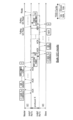
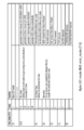
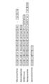
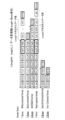
- FIG. 1 A block diagram of a communication system that embodies FIG. 1.
- Master SerDes is an equivalent block diagram when performing I2C communication between Master and Slave SerDes.
- Timing diagram of Bulk I2C mode in TDD system Timing diagram of Byte I2C mode in TDD system.
- FIG. 11C is a diagram illustrating a method of calculating the position of End of Data in the third example.
- Timing diagram of the basic Write model in which Slave SerDes automatically generates the number of clock CLKs in ByteI2C mode The timing diagram of the Write operation 2 which is a modification of the Write operation 1 of FIG. Timing diagram of basic Write operation 3 that specifies the number of clock CLKs in ByteI2C mode.
- the timing diagram of the Write operation 4 which is a modification of the Write operation 3 of FIG. Timing diagram of the basic Read model in which Slave SerDes automatically generates the number of clock CLKs in ByteI2C mode.
- the timing diagram of the Read operation 2 which is a modification of the Read operation 1 of FIG. 22.
- Timing diagram of Err operation 1 in ByteI2C mode Timing diagram of Err operation 2 in ByteI2C mode.
- the figure which shows the signal sent and received between Master and Master SerDes in Bulk I2C mode The figure which shows an example of the data which is stored in the table1 in mem1 in BulkI2C mode.
- the figure which shows the data at rest in mem1 before the storage area for Random Write Command is released in Bulk I2C mode.
- the figure which shows the batch command transmission by Cmd_mode [7] 1 in Bulk I2C mode.
- the figure which shows the process of Master SerDes when the reply from Slave SerDes to Random Read Command is received in Bulk I2C mode The figure which shows an example of the data in mem1 after receiving the reply data from Slave SerDes to Random Read Command in Bulk I2C mode.
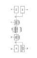
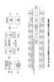
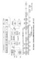
- FIG. 1 is a block diagram showing a schematic configuration of a communication system provided with a communication device according to an embodiment
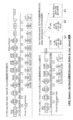
- FIG. 2 is a block diagram of a communication system in which FIG. 1 is more embodied.
- the communication system of FIGS. 1 and 2 is, for example, a camera image recognition system which is a part of ADAS (Advanced Driver Assistance System).
- ADAS Advanced Driver Assistance System
- the communication devices of FIGS. 1 and 2 include ECU 4 and SoC 5 that can operate as Master 21, image sensor 12 and temperature sensor 14 that can operate as Slave 22, Master SerDes 7, and Slave SerDes 13. ing.
- Master SerDes 7 and Slave SerDes 13 are connected to each other so that they can communicate with each other according to a predetermined communication standard (hereinafter referred to as "communication standard X").
- the predetermined communication standard X includes, for example, FPD-Link III, A-phy, ASA, and the like, and is not limited.
- Each of Master SerDes 7 and Slave SerDes 13 corresponds to the communication device according to this embodiment.
- Master SerDes 7 may be referred to as SerDes 1
- Slave SerDes 13 may be referred to as SerDes 2.
- Master 21 and Master SerDes 7 are connected to each other so that they can communicate with each other by, for example, I2C (Inter-Integrated Circuit) communication.
- I2C Inter-Integrated Circuit
- the communication between Master 21 and Master SerDes 7 is not limited to I2C communication, and may be communication using, for example, GPIO (General Purpose Input / Output).
- Slave 22 and Slave SerDes 13 are connected to each other so as to be able to communicate with each other by, for example, I2C communication.
- the communication between Slave 22 and Slave SerDes 13 is not limited to I2C communication, and may be communication using GPIO, for example.
- the signal path on the transmission path 6 for serially transmitting information from Slaver SerDes 13 to Master SerDes 7 is called a downlink or forward channel, and transmission for serially transmitting information from Master SerDes 7 to Slave SerDes 13.
- the signal path on the path 6 is called an uplink or a levers channel.
- the ECU 4 controls the entire communication system 3 and has I2C 4a.
- the ECU 4 receives an image signal from Master SerDes 7 and performs I2C communication with Master SerDes 7 via I2C 4a.
- SoC5 is for performing image recognition and video processing, for example, and has I2C5a.
- the SoC 5 receives an image signal from the Master SerDes 7 and performs I2C communication with the Master SerDes 7 via the I2C 5a.
- the image sensor 12 captures an image and has I2C 12a and mem 19.
- the image sensor 12 outputs the image data of the captured image to the Slave SerDes 13, and also performs I2C communication with the Slave SerDes 13 via the I2C 12a.
- the image sensor 12 may be referred to as a CIS (CMOS image sensor).
- the mem 19 can store the pixel data captured by the image sensor 12 and the data transmitted from the Master 21.
- mem19 may be referred to as mem3.
- the temperature sensor 14 measures the temperature of an arbitrary object (for example, image sensor 12) and has I2C 14a.
- the temperature sensor 14 communicates with Slave SerDes 13 via I2C 14a via I2C, and transmits temperature data related to the measured temperature to Slave SerDes 13.
- Master SerDes 7 converts the I2C protocol signal received from Master 21 into a communication standard X protocol signal and sends it to Slave SerDes 13, and also formats and converts the communication standard X protocol signal received from Slave SerDes 13 as appropriate. Then, image data and I2C protocol signals are generated and output to Master21.
- This Master SerDes 7 has LINK 11, forward receiver (Fw.Rx) 9, reverse transmitter (Rv.Tx) 10, and I2C 7a.
- LINK 11 converts the I2C protocol signal received from Master 21 via I2C 7a into a communication standard X protocol signal and sends it to Slave SerDes 13 via Rv.Tx 10. In addition, LINK 11 generates image data from the communication standard X protocol signal received from Slave SerDes 13 via Fw.Rx 9 and sends it to Master 21, or is an I2C protocol that contains information other than image data. It generates the signal of and outputs it to Master21 via I2C7a.
- Slave SerDes 13 converts the I2C protocol signal and image signal received from Slave 22 into a communication standard X protocol signal and sends it to Master SerDes 7, and also transmits the communication standard X protocol signal received from Master SerDes 7. Format-convert it to an I2C protocol signal as appropriate and output it to Slave 22.
- This Slave SerDes 13 has I2C 13a, LINK 17, forward transmitter (Fw.Tx) 16, reverse receiver (Rv.Rx) 15, and I2C 13a.
- LINK 17 converts the I2C protocol signal and image data received from Slave 22 via I2C 13a into a communication standard X protocol signal and sends it to Master SerDes 7 via Fw.Tx16. In addition, LINK 17 converts the communication standard X protocol signal received from Master SerDes 7 via Rv.Rx 15 into an I2C standard signal, and transmits it to Slave 22 via I2C 13a. At this time, the following problems 1) and 2) may occur.
- Master 21 transmits each information unit such as 1 byte. In addition, it is necessary to receive the ACK signal or NACK signal from Slave22. At this time, the propagation delay of I2C communication via Master SerDes 7 and Slave SerDes 13 may generally be larger than the period of one clock of I2C communication (the frequency of one clock is 400 kHz or 1 MHz, etc.).
- Master SerDes 7 receives the ACK signal or NACK signal from Slave 22 from Slave SerDes 13, completes the I2C protocol conversion, and prepares to output the ACK signal or NACK signal to Master 21 via I2C 7a. Keep the clock (SCL) of the I2C protocol signal at the low level until it is ready. After the Master SerDes 7 is ready to output the ACK signal or NACK signal transmitted by the Slave 22 to the Master 21, the low level of the clock (SCL) of the held I2C protocol signal is released. As a result, Master 21 can resume I2C communication and receive an ACK signal or an NACK signal.
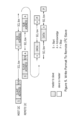
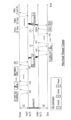
- FIG. 3 shows I2C communication when writing from HOST I2C (for example, Master 21) to REMOTE I2C (for example, Slave 22) via Master SerDes 7 and Slave SerDes 13.
- HOST I2C for example, Master 21
- REMOTE I2C for example, Slave 22
- Slave SerDes 13 the SCL low section of HOST I2C indicates that Master SerDes7 keeps the SCL at the low level until it is ready to output the ACK signal or NACK signal from Slave22.
- HOST I2C indicates that I2C communication is not possible.
- Slave SerDes 13 In addition to image sensor 12 and temperature sensor 14, it is preferable that various devices can be connected to Slave SerDes 13 as Slave 22. These various Slave 22s may have different I2C operating clocks. For this reason, Slave SerDes 13 is expected to perform I2C communication with various Slave 22s, and the I2C operating clock of Slave 22 (the operating clock of I2C communication between Slave 22 and Slave SerDes 13) is more than necessary. May be set low.
- a storage device (mem 11a in FIG. 1) is provided in the Master SerDes 7, and the Master SerDes 7 receives 1 byte from the Master 21. Then, the 1 byte is stored in the storage device, and the ACK signal or the NACK signal is returned to the Master 21 instead of the Slave 22. Therefore, the period of SCL low extended by Master 21 can be shortened.
- the Master 21 sets the CLK_value (Data [0]) described later, and the Slave is at the frequency specified by the CLK_value (Data [0]). Allow SerDes 13 to perform I2C communication with Slave 22. Therefore, Slave 22 and Slave SerDes 13 can realize I2C communication at a specified frequency.
- LINK11 in FIG. 2 has I2CCmdUnit8 and mem11a.
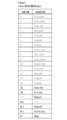
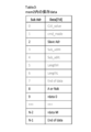
- I2CCmdUnit8 stores table2 in ROM (not shown), and mem11a stores table1.
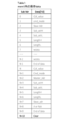
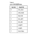
- mem11a is a volatile memory. In the present specification, mem11a may be referred to as mem1. Every time this LINK 11 receives 1 byte from Master 21 via I2C 7a, it writes that 1 byte to table 1 of mem 11a and returns an ACK signal or NACK signal to Master 21 instead of Slave 22 to specify. When the condition of (End of data is written, etc.) is satisfied, table1 is read and sent to Slave SerDes 13 via Rv.Tx10.
- LINK11 writes the signal received from Slave SerDes 13 via Fw.Rx to table1 of mem11a, and when certain conditions are met (such as writing to End of data), it reads table1 and I2C7a.
- I2C communication is performed with Master21 via Fw.Rx9, and at the same time, image data taken by ImageSensor12 received from SlaveSerDes13 via Fw.Rx9 is transmitted to Master21.
- LINK17 in FIG. 2 has I2CCmdUnit18 and mem17a.
- I2CCmdUnit18 stores table2 in ROM (not shown), and mem17a stores table3.
- mem17a may be referred to as mem2.
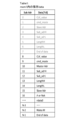
- This LINK 17 writes the signal received from Master SerDes 7 via Rv.Rx15 to table 3 of mem 17a, and when certain conditions are met (such as writing to End of data), reads table 3 and reads I2C 13a. Send to Slave 22 via.
- LINK 17 performs I2C communication with Slave 22 via I2C 13a and receives a signal, or receives temperature data converted from temperature sensor 14 to the I2C protocol via I2C 13a, it receives them.
- Write to table3 of mem17a and when certain conditions are met (such as writing to End of data), read table3 and send it to Master SerDes 7 via Fw.Tx16.
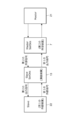
- FIG. 4 is an equivalent block diagram when Master SerDes 7 performs I2C communication between Master 21 and Slave SerDes 13 among the communication systems 3 of FIGS. 1 and 2.
- Master SerDes 7 is a communication device
- Master 21 is a first external device
- Slave SerDes 13 is a second external device.
- the communication device (Master SerDes 7) of FIG. 4 generates a first output signal based on the first external signal from the first external device (Master 21), and generates a first output signal to the second external device (Slave SerDes 13). Output to. Further, the communication device (Master SerDes 7) generates a second output signal based on the second external signal from the second external device (Slave SerDes 13) to the first external device (Master 21). Output.
- FIG. 5 is an equivalent block diagram when Slave SerDes 13 performs I2C communication between Slave 22 and Master SerDes 7 among the communication systems 3 of FIGS. 1 and 2.
- Slave SerDes 13 is a communication device
- Slave 22 is a first external device
- Master SerDes 7 is a second external device.
- the communication device (Slave SerDes 13) of FIG. 5 generates a first output signal based on the first external signal from the first external device (Slave 22), and the second external device (Master SerDes 7). Output to. Further, the communication device (Slave SerDes 13) generates a second output signal based on the second external signal from the second external device (Master SerDes 7) to the first external device (Slave 22). Output.
- Each of the first output signal and the second external signal in FIGS. 4 and 5 has command information Cmd_mode indicating the content of a command transmitted from the first external device and data transmitted from the first external device.
- the final destination device identification information Slave_Adr that identifies the final destination device, the internal address information Sub_Adr of the final destination device, the data length information Length of the data transmitted from the first external device, and the data length information Length transmitted from the first external device.
- Data end position information End of Data is included.
- Slave_Adr may be placed next to Cmd_mode
- Sub_Adr may be placed next to Slave_Adr
- Length may be placed next to Sub_Adr.
- Cmd_mode may include command format information Cmd_mode [2: 0] that defines the command format on the communication standard X, including the function of identifying the Write and Read instructions. That is, Cmd_mode may include Cmd_mode [2: 0] that defines a command format on a predetermined communication standard between the communication device and the second external device.
- Cmd_mode includes at least Cmd_mode [0] -Cmd_mode [7], and the data end determination condition information Cmd_mode [7] may specify the condition for end determination of the data transmitted from the first external device.
- Each of the first output signal and the second external signal may further include the communication frequency information CLK_value that specifies the communication frequency between the second external device and the final destination device.
- the first output signal and the second external signal include a command in which an I2C (Inter-Integrated Circuit) communication command is protocol-converted into a predetermined communication standard between the communication device and the second external device. You may.
- I2C Inter-Integrated Circuit
- the LINK 11 and 17 transmit an ACK signal indicating an acknowledgment or a NACK signal indicating a negative response to the first external device. You may.
- LINK11,17 has a storage unit that stores a signal corresponding to the first external signal and a signal corresponding to the second external signal.
- the LINKs 11 and 17 collectively convert the first external signal received and stored in the storage unit into a protocol, and then output the first output signal. May be generated.
- Protocol conversion by LINK11, 17 may be protocol conversion corresponding to TDD (Time Division Duplex).
- the LINKs 11 and 17 transmit the first output signal to the second external device, and when they receive the information indicating that the processing for the first output signal is completed from the second external device, the LINK 11 and 17 send a signal indicating the processing completion. It may be stored in the storage unit.
- LINK11, 17 may release the storage area of the storage unit based on the command from the first external device.
- LINK11, 17 outputs the processing completion information for the second external signal transmitted from the second external device to the first external device in response to the request signal from the first external device, or the first An interrupt request flag for performing interrupt processing for the external device may be output to the first external device.
- LINK11, 17 first uses a first external signal including output instruction information cmd_done indicating the output of the first output signal and transmission end information P (STOP condition) indicating the end of transmission of the first external signal. It may be received from an external device of.
- LINK11, 17 cancels the transmission end of the first external signal when the first value is received as the data end determination condition information for specifying the condition for the end determination of the data transmitted from the first external device.
- the indicated transmission end information P STOP condition
- LINK11, 17 is the data end judgment condition information to be received after the second value is received as the data end judgment condition information for specifying the condition for the end judgment of the data transmitted from the first external device.
- LINK11, 17 may release the storage area of the storage unit after transmitting the first output signal to the second external device.
- LINK11, 17 outputs the signal after performing the protocol conversion to the second output signal for the signal based on the second external signal stored in the storage unit to the first external device for each information unit. And, at least one of receiving each information unit constituting the first external signal output from the first external device may be performed within a predetermined number of times or time.
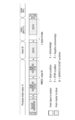
- FIG. 6 is a diagram showing an example of the frame structure of the signal of the communication standard X protocol transmitted / received between Master SerDes 7 and Slave SerDes 13.
- the frame structure of FIG. 6 contains a plurality of containers between the Sync pattern and Parity.
- the Sync pattern is a signal pattern for synchronizing the physical layers of Master SerDes 7 and Slave SerDes 13.
- the plurality of containers include, for example, about 2 to 100 containers.
- the number of containers included in the frame structure changes depending on the signal transmission state.
- Parity is a bit or bit string for error detection or error correction processing.
- the structure of the container includes Header, Payload, and Parity.
- Header includes address information indicating the transmission destination of Payload and the like.
- Payload is the main body of the signal sent and received.
- Payload includes OAM (Operations, Administration, Maintenance) for SerDes control in addition to video signals.
- Parity is a bit or bit string for error detection or error correction processing of Payload.
- Palyload contains each information of CLK value, Cmd_mode, Slave Adr, length, data and End of data.
- the CLK value is the operating clock of Slave 22, that is, the SCL frequency used by Slave SerDes 13 for I2C communication with Slave 22.
- Cmd_mode indicates the content of the command sent from Master21.
- SlaveAdr is address information that identifies Slave22.
- length is the length of the data transmitted from Master 21.
- End of data is the end position of the data transmitted from Master 21.
- Cmd_ID is identification information for distinguishing and identifying the command sent from Master21.
- I2C communication is performed between Master 21 and Master SerDes 7, and I2C communication is also performed between Slave SerDes 13 and Slaver 22.
- I2C communication every time information of a predetermined number of bytes (for example, 1 byte or 2 bytes when the error correction code is not transmitted, 2 bytes or 3 bytes when the error correction code is transmitted) is transmitted, the ACK signal / A first mode for receiving NAK signals (also called Byte I2C mode) and a second mode for receiving ACK / NAK signals each time bulk information, which is a block of multi-byte information, is transmitted (Bulk I2C mode). You can select either and.
- the FDD Frequency Division Duplexing
- the FDD method does not require switching between uplink and downlink, and information can be transmitted from Master 21 to Slave 22 or from Slave 22 to Master 21 at any time.
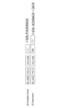
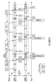
- FIG. 9A is a timing diagram of the Bulk I2C mode in the TDD system
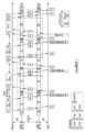
- FIG. 9B is a timing diagram of the Byte I2C mode in the TDD system.
- Master SerDes 7 transmits a signal including an ACK signal or an NACK signal to Master 21 each time a multi-byte signal transmitted from Master 21 is received byte by byte as shown in FIG. 9A.
- Master SerDes 7 collectively sends the converted signals to Slave SerDes 13 after the conversion of the multi-byte signal received from Master 21 is completed.
- the Master SerDes 7 receives 1 byte of data from Master 21, conversion from the I2C protocol to communication protocol X is performed, and from Master 21 to multiple bytes of data. In some cases, the conversion from the I2C protocol to the communication protocol X may be performed collectively after receiving all of the above. After that, the Master SerDes 7 receives and holds a communication protocol X (first communication standard) signal including an ACK signal or a NACK signal from the Slave SerDes 13. After that, the Master SerDes 7 converts the signal of the communication protocol X into the signal of the I2C protocol (second communication standard) and transmits it to the Master 21 in response to the read request from the Master 21.
- a communication protocol X first communication standard
- the Master SerDes 7 converts the signal of the communication protocol X into the signal of the I2C protocol (second communication standard) and transmits it to the Master 21 in response to the read request from the Master 21.
- the signal transmitted to Slave SerDes 13 includes command information indicating the content transmitted from Master 21, and the signal transmitted to Master 21 includes information transmitted from Slave SerDes 13. Further, in Bulk I2C mode, Slave SerDes 13 converts the received signal into an I2C protocol signal when it receives a multi-byte signal of communication protocol X transmitted from Master SerDes 7 as shown in FIG. 9A. , Send the converted signal byte by byte to Slave 22. Each time the converted signal is transmitted byte by byte to Slave 22, an I2C protocol signal including an ACK signal or NACK signal from Slave 22 is received and held. After the signal from Master SerDes 7 has been transmitted to Slave 22, the signal of communication protocol X corresponding to the held signal is transmitted to Master SerDes 7.
- Master SerDes 7 converts the 1-byte signal transmitted from Master 21 into the signal of the first communication standard as a unit, and the converted signal is Slave SerDes. After transmitting to 13, the signal of the first communication standard including the ACK signal representing the affirmative response or the NACK signal representing the negative response transmitted from Slave SerDes 13 is received, and the received signal is of the second communication standard. Converts to a signal and sends it to Master21.
- the Slave SerDes 13 receives the signal of the first communication standard transmitted from the Master SerDes 7 in the Byte I2C mode, as shown in FIG. 9B, the Slave SerDes 13 receives the signal of the second communication standard in units of the received signal. After converting to a signal and transmitting the converted signal to Slave 22, a signal of the second communication standard including an ACK signal representing an acknowledgment or a NACK signal representing a negative response transmitted from Slave 22 is received and received. The signal is converted into a signal of the first communication standard and transmitted to Master SerDes 7.
- Cmd_mode may be referred to as command information.
- Cmd_mode is, for example, 1-byte information, and the information of each bit is different between Bulk I2C mode and Byte I2C mode.
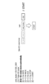
- FIG. 10A is a diagram showing an example of cmd_mode in Bulk I2C mode.
- the bit [7] of cmd_mode in FIG. 10A is the mode selection described above, and if it is 1, it indicates ByteI2C mode, and if it is 0, it indicates BulkI2C mode.
- Bit [6] is a bit that specifies whether or not to retry when the NACK signal is received in the Slave side I2C communication. 1 indicates that the retry is performed, and 0 indicates that the retry is not performed.
- Bit [5] is a bit indicating the operation of SlaveSerDes13 when SlaveSerDes13 receives a NACK signal while accessing Slave22, and 1 is a RAW for writing by ignoring NACK and performing processing. Continue to output data, 0 indicates that normal processing is performed.
- Bit [4] is the batch transmission mode of I2C commands, and 1 indicates that it is transmitted at End of data and cmd_doen. 0 indicates that the end is determined and transmitted for each End of data.
- Bit [3] is the selection of the I2C address mode on the Slave side, 1 indicates the address of the current position without the offset address, and 0 indicates the address of the current position with the offset address.
- Bit [2: 0] is the I2C format type of communication standard X, 111 is the error command format, 110 is the special command format, 10X is the reserve, 011 is the Read response format, 010 is the AC / NACK format, 001. Indicates the Read command format, and 000 indicates the Write command format.
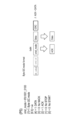
- FIG. 10B is a diagram showing an example of cmd_mode in Byte I2C mode.
- the bit [7] of the cmd_mode of FIG. 10B is the same as the bit [7] of FIG. 10A, and may be referred to as the first information in the present specification.
- Bit [6: 5] is the clock mode selection and is sometimes referred to herein as second information.
- the clock mode is a mode in which node2 automatically generates a clock signal for Slave SerDes 13 in which master SerDes 7 which is node 1 is node 2, and a mode in which node 1 uses node 2 instead of node 2 and the number of clock CLK cycles is 9/8. It includes a mode to calculate and notify / 1.
- node2 In 11, node2 generates 9 clock signals including ACK / NACK signals and data. In 10, node2 generates 8 clock signals including data. For 01, node2 generates one clock signal including an ACK / NACK signal. For 00, node2 automatically generates 9/8/1 clock signals.
- Bit [4: 0] is an I2C packet type that defines packetized I2C data.
- the bit [4] is information indicating whether the data is for Write or Read, or other data, and may be referred to as a third information in the present specification. 1 of bit [4] indicates that the write / read data packet is followed. Bit [4] 0 indicates that there are no Write / Read data packets.
- Bit [3] is information indicating whether or not a NACK signal has been received, and may be referred to as fourth information in the present specification. 1 of bit [3] indicates that the NACK signal was received from Slave 22 or Master 21, and 0 indicates that the NACK signal was not received.
- Bit [2] is information indicating whether or not an ACK signal has been received, and may be referred to as fifth information in the present specification. 1 of bit [2] indicates that the ACK signal was received from Slave 22 or Master 21, and 0 indicates that the ACK signal was not received.
- the bit [1] is information indicating whether or not the STOP command is included, and may be referred to as a sixth information in the present specification. 1 in bit [1] indicates that the STOP command was detected, and 0 indicates that the STOP command was not detected.
- Bit [0] is information indicating whether or not the START / ReSTART command is included, and may be referred to as the seventh information in the present specification. 1 in bit [0] indicates that the START / ReSTART command was detected, and 0 indicates that the START / ReSTART command was not detected.
- cmd_mode shown in FIGS. 10A and 10B is an example, and what kind of information is assigned to each bit of the cmd_mode is arbitrary. Further, cmd_mode may have a byte length of 2 bytes or more.
- FIG. 11A is a diagram showing a first example of a command format transmitted / received by I2C communication when the Bulk I2C mode is selected.
- the Write command format includes clk_value, cmd_mode, Sl_adr, Sub_adrH, Sub_adrL, lengthH, lengthL, WDATA, End of data.
- the Read command format is the same as the Write command format except that it does not include WDATA.
- the ACK / NACK command format includes clk_value, cmd_mode, Master_adr, Sub_adrH, Sub_adrL, lengthH, lengthL, Sl_adr, ACK / NACK, and End of data.
- the Read response format is the ACK / NACK command format with RDATA added.
- Special command formats include clk_value, cmd_mode, Cmd_done, and End of data.
- FIG. 11B is a diagram showing a second example of a command format transmitted / received by I2C communication when Bulk I2C mode is selected.
- CRC which is an error correction code
- Error command formats include clk_value, cmd_mode, End of data, and CRC. The error command format will be described later.
- FIGS. 11A and 11B include End of Data (EoD) near the end of each command format, but EoD can be omitted.
- FIG. 11C is a diagram showing a third example of a command format transmitted / received by I2C communication when the Bulk I2C mode is selected, and EoD is omitted from each format of FIG. 11A. Even if EoD information is used inside Master SerDes 7 and Slave SerDes 13, the communication format between Master SerDes 7 and Slave SerDes 22 is the receiving side from the cmd_mode, lengthH, and lengthL information even if there is no EoD. You can calculate the data end position with.
- EoD End of Data
- FIG. 11D is a diagram illustrating a method of calculating the position of End of Data in the third example of FIG. 11C.
- the Read command format, ACK / NACK format, special command format, and error command format each have a fixed byte length. More specifically, the Read command format is 7 bytes, the ACK / NACK format is 9 bytes, the special command format is 3 bytes, and the error command format is 2 bytes. Therefore, the end position of each format can be specified without EnD.
- the ACK / NACK format is not always fixed at 9 bytes. All ACKs / NACKs received during I2C communication may be added.
- FIG. 11E is a diagram showing the first example of the command format when the Byte I2C mode is selected. As shown in FIG. 11E, when the Byte I2C mode is selected, the I2C condition format or the I2C data format is selected.
- the I2C condition format includes cmd_mode and CRC.
- the I2C commands sent in the I2C condition format are S (START), Sr (ReSTART), P (STOP), and ACK / NACK.
- the I2C data format includes cmd_mode, Data and CRC.
- the I2C commands transmitted in the I2C data format are S (START), Sr (ReSTART), P (STOP), and ACK / NACK + data.
- FIG. 11F is a diagram showing a second example of the command format when the Byte I2C mode is selected.
- the second example of FIG. 11F shows an example in which clk_value and cmd_id are added immediately before the cmd_mode of the first example of FIG. 11E.
- Whether or not to add CRC to the end of each format in the second example of FIG. 11F is arbitrary. The same applies to the first example of FIG. 11E.
- FIG. 12 is a diagram showing the types and bit strings of I2C commands transmitted on the communication standard X protocol in Bulk I2C mode.
- ACK is an acknowledgment, indicating that the process was completed normally.
- NACK is a negative response, indicating that the process did not end normally.
- Repeated_start is a start flag that indicates that the I2C protocol signal is continuing. Specifically, it corresponds to Sr in the combined format of I2C shown in FIG. After starting I2C communication from Master 21 to Master SerDes 7 (after issuing S (START condition)), Sr does not end this I2C communication (without issuing P (STOP condition)). This is a flag issued before starting the next I2C communication when starting the I2C communication of.
- End of data in the I2C command transmitted on the communication standard X protocol indicates P (STOP condition).
- Cmd_mode [4] 0 in Bulk I2C mode, it indicates that the I2C protocol signal from S (START condition) to P (STOP condition) is transmitted to Slave SerDes 13.
- cmd_done is information instructing Slave SerDes 13 to send one or more sets of I2C protocol signals from S (START condition) to P (STOP condition) as one set.
- Rsv_command in the I2C command transmitted on the communication standard X protocol is Reserved and is not specified at this time.
- Data in the I2C command indicates the data to be written to Slave 22 or the data read from Slave 22.
- FIG. 12 shows an example in which the I2C command transmitted on the communication standard X protocol is represented by 8 bits, but the present invention is not limited to this and may be represented by 9 bits or more.
- the I2C protocol signal is "data"
- 1 bit on the MSB side is set to "0”
- the I2C protocol signal is other than “data”, 1 on the MSB side.
- By setting the bit to "1” it is possible to easily determine whether the signal of the I2C protocol is "data” or other than that. (Detailed operation of Byte I2C mode)
- FIGS. 13A and 13B are diagrams showing an example of setting cmd-mode when Slave SerDes 13, which is node 2, automatically generates a clock CLK.
- FIG. 13A shows a setting example of cmd_mode when condition information and an instruction for Slave SerDes 13 to automatically generate a clock CLK number are transmitted in the Byte I2C mode.
- the cmd_mode of 1-byte data is set to 8'b1000_0001.
- Bit [3] 0 indicates that the NACK signal is not received.
- Bit [2] 0 indicates that the ACK signal is not received.
- Bit [1] 0 indicates that the STOP command is not included.
- Bit [0] 1 indicates that the START command is included.
- FIG. 13B shows an example of setting cmd_mode when data and an instruction for Slave SerDes 13 to automatically generate a clock CLK number are transmitted in Byte I2C mode.
- cmd_mode is set to 8'b1001_0000.
- Bit [0] 0 indicates that the START command is not included.
- the number of bytes of the signal transmitted from Mster SerDes 7 to Slave SerDes 13 in the Byte I2C mode is 2 bytes or 3 bytes excluding the clock frequency information clk_value and the error correction code CRC. ..
- FIG. 14A and 14B are diagrams showing an example in which Slave SerDes 13 which is node 2 manually generates a clock CLK based on the number of cycles specified by Msater SerDes 7 which is node 1.
- FIG. 14A shows a setting example 1 of cmd-mode when the condition information and data and the clock CLK number specification generated by Slave SerDes are transmitted in the Byte I2C mode.
- FIG. 14B shows a setting example 2 of cmd-mode when the condition information and data and the clock CLK number specification generated by Slave SerDes are transmitted in the Byte I2C mode.
- cmd_mode in FIG. 14B is set to 8'b1111_0001.
- Bit [6: 5] 11 in cmd_mode indicates that node2 indicates the generation of a clock CLK with 9 cycles.
- the other bits are the same as in FIG. 14A.
- FIG. 15A shows an example of transmitting ACK and data in Byte I2C mode.
- FIG. 15B shows an example of transmitting the NACK and STOP commands in the Byte I2C mode.
- FIG. 16 is a diagram showing an example of setting cmd_mode when an error occurs.
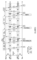
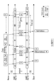
- FIG. 17 is a state transition diagram of Master SerDes 7 which is node 1 and Slave SerDes 13 which is node 2. Both node1 and node2 change their states based on the state transition diagram shown in FIG.
- the state transition diagram of FIG. 17 shows the state transition in the Byte I2C mode of FIG. 9B.
- S START condition
- P STOP condition
- Node1 and node2 shift to the initial state init when the power is turned on (state S1).
- state S1 When the S / Sr (START / ReSTART) command of the I2C protocol from Master21 is received in the initial state init, node1 transitions to the START state ST (state S2).
- START state ST When node1 is in the START state ST, the S / Sr (START / ReSTART) command of the I2C protocol received in the state S1 is converted into a packet of the communication standard X of FIG. 13A and transmitted to node2.
- node2 When node2 receives the S / Sr (START / ReSTART) command from node1, it transitions to the Start state ST and sends the S / Sr (START / ReSTART) command converted to the I2C protocol to Slave22.
- node 1 When node 1 receives data D from Master 21 in the Start state ST, it determines whether or not the data is a Slave address (state S3). If it is not a Slave address, it returns to the state S1. If it is a Slave address, it transitions to the Slave address state Sl_Addr (state S4). node1 instructs Master21 to clock stretch in Slave address state Sl_Addr. Clock stretch means to hold the clock from Master 21 at a low level. During the clock stretch period, Master21 cannot send new information to node1. In the Slave address state Sl_Addr, node 1 converts the Slave address of the I2C protocol into a packet of communication standard X and sends it to node 2.
- node2 When node2 receives the Slave address from node1, it transitions to the Slave address state S1_Addr and sends the Slave address converted to the I2C protocol to Slave22.
- node2 receives an ACK / NACK signal from Slave22 in the Slave address state S1_Addr, it transitions to the Write state W, converts the ACK / NACK signal to the communication standard X protocol, and sends it to node1. ..
- node1 When node1 receives an ACK / NACK signal from node2 when the Slave address state is Sl_Addr, it transitions to the Write state W (state S5). In the Write state W, the master 21 is instructed to cancel the clock stretch, and the ACK / NACK signal from node 2 is converted into the I2C protocol and transmitted to the master 21.
- node 1 receives data D from Master 21 in the write state W, it transitions to the write data state WD (state S6). If an ACK / NACK signal is returned to Master 21 in this state, it returns to the Write state W.
- node1 When node1 receives the P (STOP) command from Master21 in the Write state W, it transitions to the End state End (state S7). When the End state is End, if the P (STOP) command of the I2C protocol is converted into a packet of communication protocol X and sent to node2, the initial state init is restored.
- node 2 When node 2 receives the Slave address including the Read bit and transitions to the Slave address state Sl_Addr in the state S4, and receives the ACK or NACK from the Slave 22, it transitions to the Read state R (state S8). After that, node 2 converts the I2C protocol ACK or NACK into a communication protocol X packet and sends it to node 1. When the data D from Slave is received in the Read state R, the state transitions to the Read data state RD (state S9). node 2 converts the Read data into an I2C protocol packet of communication protocol X and sends it to node 1.
- node 1 When node 1 receives the ACK / NACK packet from node 2, it transitions to the Read state R and sends ACK or NACK to Master 21. After that, when it receives a Read data packet, it transitions to the Read data state RD and sends Read data to Master21. If the ACK / NACK signal is not received within the time limit in the Read data state RD, the time is over and the state transitions to the data error state (state S10). Similarly, when the data D from Slave is not received within the time limit in the Read state R, the time is over and the state transitions to the data error state in the state S10. When a dummy data signal is returned to Master 21 in the data error state, it returns to the Read state R of the state S8.
- the state transitions to the ACK error state a_err (state S11). Further, even if the ACK / NACK signal from Slave is not received within the time limit when the Slave address state Sl_Addr is in the state S4, the state transitions to the ACK error state a_err in the state S11. If a predetermined error process is performed in the ACK error state a_err, the state returns to the state S1.
- LINK 11 converts the signal including the address information into the signal of the communication protocol X and transmits it to Slave SerDes 13. After that, when LINK 11 receives a signal including an ACK signal or a NACK signal from Slave SerDes 13 while in the Slave address state S1_Addr, the LINK 11 writes if the specific bit of the signal including the address information is the first bit value. Recognizes that and transitions to the Write state W (third state). In the Write state W, the LINK 11 converts the ACK signal or the signal including the NACK signal received from the Slave SerDes 13 into an I2C protocol (second communication standard) signal and transmits it to the Master 21, and then the Master 21. Release the low level hold of the clock from.
- I2C protocol second communication standard
- LINK 11 when LINK 11 receives a signal including 1 byte of write data from Master 21 while in the write state W, it transitions to the write data state WD (fourth state). In the Write data state WD, LINK 11 converts the received signal into a signal of communication protocol X and transmits it to Slave SerDes 13. After that, when LINK 11 receives a signal including an ACK signal or a NACK signal from Slave SerDes 13 while in the Write data state WD, it transitions to the Write state W and converts the received ACK / NACK signal into an I2C protocol signal. Convert and send to Master21.
- ACK error state a_err (fifth). (State), and error processing is performed in the ACK error state a_err.
- the state transitions when Master SerDes 7 reads out the Byte I2C mode can be summarized as follows.
- LINK11 in MasterSerDes7 receives a signal including StartCondition or ReStartCondition from Master21, it transitions to the Start state ST.
- the received signal including the Start Condition or ReStart Condition is converted into a signal of the communication protocol X and transmitted to the Slave SerDes 13.
- LINK11 receives a signal containing the address information of the final destination device of 1 byte from Master21 while in Start state ST, it transitions to Slave address state S1_Addr and lowers the clock from Master21. Hold to.
- LINK 11 converts the signal including the address information into the signal of the communication protocol X and transmits it to Slave SerDes 13. After that, when LINK 11 receives a signal including an ACK signal or a NACK signal from Slave SerDes 13 while in the Slave address state S1_Addr, the LINK 11 reads out if the specific bit of the signal including the address information is the second bit value. Recognizes that and transitions to the Read state R (sixth state). In the Read state R, LINK11 converts the signal including the ACK signal or NACK signal received from Slave SerDes 13 into an I2C protocol signal and sends it to Master21, and then holds the low level of the clock from Master21. To cancel.
- LINK 11 when LINK 11 receives a signal including 1 byte of read data from Slave SerDes 13 while in Read state R, it transitions to Read data state RD (seventh state). In Read data state RD, LINK11 converts the received signal into an I2C protocol signal and sends it to Master21. After that, when LINK11 receives a signal including an ACK signal or a NACK signal from Master21 while in Read data state RD, it transitions to Read state R and converts the received signal into a signal of communication protocol X. Send to Slave SerDes 13.
- LINK 11 transitions to the data error state d_err (eighth state) when the read data is not received from Slave SerDes 13 within the predetermined period while in the Read state R.
- LINK11 transitions to the data error state d_err when it does not receive the ACK signal or NACK signal from Master21 within the predetermined period when it is in the Read data state RD.
- LINK11 avoids the deadlock of the entire system including the communication device, Master21, and Slave SerDes 13 by performing error processing in the data error state d_err.
- Master SerDes 7 summarizes the state transitions of Bulk I2C mode as follows.
- LINK11 in MasterSerDes7 holds the received signal from the reception of the signal including StartCondition to the reception of the signal including StopCondition from Master21, and holds the received signal and ACK signal for each byte of the received signal.
- a signal including the NACK signal is transmitted to Master21.
- LINK 11 converts the received signal into a signal of communication protocol X, and transmits the converted signal to Slave SerDes 13.
- LINK 11 receives and holds a signal including an ACK signal or NACK signal from Slave 22 from Slave SerDes 13, and then, in response to a read request from Master 21, converts the signal from Slave SerDes 13 into an I2C protocol signal. Convert and send to Master21.
- FIG. 18 is a timing diagram of a basic Write model (hereinafter referred to as Write operation 1) in which Slave SerDes automatically generates a clock CLK number in Byte I2C mode.
- node2 can send Write data to Slave 22 and receive an ACK signal from Slave 22 by using this clock CLK.
- FIG. 19 is a timing diagram of the write operation 2 which is a modification of the write operation 1 of FIG.
- the START command was sent to node2 when node1 was in the START state St, but in Write operation 2, the START command and data D were combined when node1 was in the Slave address state Sl_Addr. And send it to node2.
- the number of transactions of the communication protocol X can be reduced as compared with the Write operation 1 of FIG.
- FIG. 20 is a timing diagram of the basic write operation 3 in which the number of clock CLKs is specified in the Byte I2C mode.
- node1 specifies information on the number of clock CLK cycles used by node2 in cmd_mode. In this case, one cycle is specified.
- node2 receives the ACK signal from Slave 22 using this clock CLK.
- FIG. 20 is adopted, for example, when the processing performance of node2 is low.
- node1 replaces node2 and calculates the required number of clock CLK cycles.
- FIG. 21 is a timing diagram of the write operation 4, which is a modification of the write operation 3 of FIG.
- the START command was sent to node2 when node1 was in the START state St, but in Write operation 4, the START command and data D were collectively sent to node2 when node1 was in the Slave address state Sl_Addr. Send to.
- transactions of a specific protocol X can be reduced as compared with the Write operation 3.
- FIG. 22 is a timing diagram of a basic Read model (hereinafter referred to as Read operation 1) in which Slave SerDes automatically generates a clock CLK number in Byte I2C mode.
- node2 receives the ACK signal from Slave 22 and receives RDATA and sends it to node1 using the clock CLK generated by itself.
- the Slave address and offset address are first transmitted to Slave 22 by the Write command, and then the same Slave address and Read command as the previous one are transmitted.
- FIG. 23 is a timing diagram of Read operation 2, which is a modification of Read operation 1 of FIG.
- node1 specifies information on the number of clock CLK cycles used by node2 in cmd_mode.
- FIG. 24 is a timing diagram of Read operation 3 when there is no Sub Address.
- the Read operation 3 shows an example in which the offset address does not exist after the Slave address, unlike the Read operations 1 and 2.
- the Slave address was first transmitted by the Write command, but in the Read operation 3, the Slave address is transmitted by the Read command from the beginning.
- node2 sends the Slave address to Slave22
- node2 receives the ACK signal and RDATA transmitted from Slave22 and sends them to node1.
- node1 transmits the ACK signal and RDATA from node2 to Master21.
- FIG. 25 is a timing diagram of Err operation 1 in the Byte I2C mode.
- the Err operation 1 is performed when the ACK / NACK signal from Slave 22 does not reach within the time limit. If the ACK / NACK signal does not reach node2 from Slave22, node1 and node2 will time out, transition to the ACK_err state a_err, perform error processing, and then return to the initial state init. When node1 transitions to the ACK_err state a_err, it returns an NACK signal to Master21 and forwards an err packet to node2. At this time, node1 may register that it is in the ACK_err state a_err in the err register.
- FIG. 26 is a timing diagram of Err operation 2 in the Byte I2C mode.
- the Err operation 2 is performed when the RDATA from Slave 22 does not arrive or when a part of the RDATA is insufficient. If RDATA does not arrive from Slave 22 to node2 within the time limit, or if part of RDATA is insufficient, node1 and node2 will time out and transition to the data_err state d_err. When node1 transitions to the data_err state d_err, it returns a dummy RDATA to Master21 and forwards an err packet to node2. At this time, node1 may register the data_err state d_err in the err register.
- Master21 can grasp that RDATA has arrived after the time is over, it can determine whether the RDATA after the time is over is dummy data or normal data by reading the err register of node1 as needed.
- Master21 When Master21 writes Random to Slave22, it first sends a command set to MasterSerDes7 via I2C communication.
- the protocol for I2C communication at the time of Random Write is shown in FIG. 7 described above, and Master 21 transmits a command set to Master SerDes 7 in accordance with this protocol.
- FIG. 27 is a diagram showing signals sent and received between Master 21 and Master SerDes 7 when Random Write is performed from Master 21 to Slave 22 in Bulk I2C mode.
- the signal of the I2C protocol from Master 21 to Master SerDes 7 is referred to as M I2C protocol.
- M Includes DatalengthH, DatalengthL, Data ⁇ 2, P (STOP condition). Details of this information will be described later.
- FIG. 28 is a diagram showing an example of data stored in table1 in mem1 in Bulk I2C mode.
- CLK_value which is the set value of the I2C setting clock CLK
- the data transmitted by the MI2C protocol thereafter is the address address where mem1 is incremented. It will be stored in.
- CLK_value is 1-byte information indicating the SCL frequency
- Slave 22 performs I2C communication with Slave SerDes 13 at the operating frequency specified by CLK_value.
- Cmd_mode of Sub_Adr [1] is 1-byte information indicating the content of the instruction received by Master SerDes 7 from Master 21.
- SlaveAdr of Sub_Adr [2] in table1 of FIG. 28 is 1-byte information indicating the address of Slave22 to be Write or Read (for example, 0x02 for imagesensor12).
- Sub_adrH of Sub_Adr [3] is the upper 1-byte information of the address indicating which Sub_adr of mem19 (mem3) in imagesensor12 is accessed or which Sub_adr of mem20 in temperaturesensor14 is accessed. Is.
- Sub_adrL of Sub_Adr [4] is the lower 1-byte information of the address indicating which Sub_adr of mem19 (mem3) in imagesensor12 is accessed or which Sub_adr of mem20 in temperaturesensor14 is accessed. Is.
- Length H of Sub_Adr [5] is the upper 1-byte information of the data length of WDATA (Data [N-2: 7]).
- LengthL of Sub_Adr [6] is the lower 1-byte information of the data length of WDATA (Data [N-2: 7]).
- WDATA of Sub_Adr [N-2: 7] is the data to be written to Slave 22. Stores 1 byte of data for each bit of Sub_Adr.
- End of Data of Sub_Adr [N-1] is written to 0x9F when P (STOP condition) is received from Master21.
- P STOP condition
- the initial value such as 0x00 is written.
- FIG. 29 is a diagram following FIG. 27, showing a process of transmitting a Random Write Command from Master SerDes 7 to Slave SerDes 13 in the Bulk I2C mode according to the communication standard X.
- the I2C protocol and mem1 (Save I2C command Packet) (steps S1 and S2) in FIG. 29 are the same as those described in FIG. 27.
- Master SerDes7 reads the data of table1 in FIG. 28, converts it into a communication standard X protocol signal, and transmits it to Slave SerDes 13 via Packetized I2C on PHY (depend on the each PHY specification) forward channel (step S3). ).
- Cmd_mode 0x00
- Cmd_mode [7] 0 means "end judgment for each End of data”. Therefore, when LINK11 of Master SerDes7 receives "End of data (0x9F)", it writes “End of data (0x9F)" to table1 of FIG. 28 and reads table1 of FIG. 28 to read Rv.Tx10. Send to Slave SerDes 13 via.
- mem1 data (table1 in Fig. 28) is collectively converted to I2C command and sent to Slave SerDes 13 via Rv.Tx10.
- FIG. 30 is a diagram showing an example of table 3 in mem2 when Random Write is operated in Bulk I2C mode. Information having the same contents as that of table1 in FIG. 28 is written in table3.
- Slave SerDes 13 converts the received data of Reverse link into a protocol and restores the original saved data of mem1 in mem2. Slave SerDes 13 determines the end of restoration of the I2C command packet by restoring End of data.
- FIG. 31 to 32 follow FIG. 29 and are diagrams showing a process of transmitting data from Slave SerDes 13 to Slave 22 by I2C communication.
- the mem2 (Save I2C command Packet) (step S4) of FIGS. 31 and 32 is described with reference to FIG. 29.
- FIG. 31 shows a process in which Slave SerDes 13 and Slave 22 send and receive data by I2C communication in Bulk I2C mode.
- (Data) Sl_adr (0x02) indicates that "0x02" is specified as the above-mentioned Sl_adr. Since it is "0x02", it means that image sensor 12 is selected.
- (Data) Sub_adrH (0x00) indicates that "0x00" is specified as the high-order bit of the address of mem3 (the target to be finally accessed) in imagesensor12.
- (Data) Sub_adrL (0x00) indicates that "0x00” is specified as the low-order bit of the address of mem3 (the target to be finally accessed) in imagesensor12.
- (Data) WDATA ⁇ 2 indicates 16 bytes of data.
- Slave 22 sequentially returns an ACK signal indicating that the signal was normally received to Slave SerDes 13 in the SI2C protocol (step S5).
- FIG. 32 is a diagram following FIG. 31 and shows a process of replying to Random Write Command from Slave SerDes 13 to Master SerDes 7 using the communication protocol X in Bulk I2C mode.
- the SI2C protocol (step S5) of FIG. 32 is described with reference to FIG. 31.
- Slave SerDes 13 converts the I2C communication result with Slave 22 into a communication standard X protocol signal and sends it to Master SerDes 7 via Packetized I2C on PHY (depend on the each PHY specification) forward channel (step). S6).
- Data [7: 0], including Cmd_ID when expanding Cmd_mode to 2 bytes) is sent to Master SerDes7.
- Slave SerDes 13 releases the storage area of mem2 shown in FIG. 33.
- Slave SerDes 13 is Sub_Adr to be written next to mem1 (it was free in mem2 and ACK / NACK was written). I know Sub_Adr.
- Slave SerDes 13 understands that if it writes to Slave 22, it is necessary to return 2 bytes (Slave adr that performed I2C communication and I2C communication result) to Master SerDes 7.
- FIG. 34 is a diagram following FIG. 32 and showing the operation of Master SerDes 7 in Bulk I2C mode.
- the Packetized I2C on PHY (depend on the each PHY specification) forward channel (step S6) of FIG. 34 is described in FIG. 32.
- Master SerDes 7 extracts the I2C command packet from the communication standard X protocol signal received from Slave SerDes 13, and writes it from N to N + 9 of Sub_Adr of table1 in mem1.
- FIG. 35 is a diagram showing table1 in mem1 after receiving reply data from Slave SerDes to Random Write Command in Bulk I2C mode.
- the I2C command packets generated by the I2C Cmd Unit in Slave SerDes 13 in FIG. 32 are stored in sub_Adr N to N + 6 and N + 9 in table 1. Further, in sub_Adr N + 7 and N + 8 of table 1 in FIG. 35, Slave adr of sub_Adr (2) in mem2 and ACK or NACK of sub_Adr (N) are read and transferred.
- FIG. 36 is a diagram showing a process when Master 21 polls Master SerDes 7 for Random Write Command and reads the execution result in Bulk I2C mode.
- Master 21 polls Master SerDes 7 for the result of the request instruction using the MI2C protocol (step S7).
- the End of Data (0x9F) and the resulting ACK (0x81) can be read.
- the polling judgment is made by looking at the result of End of Data with 1 byte read, and ACK or NACK is read again with 1 byte read, but 2 bytes are read at a time and the polling result. And the result of I2C communication to Slave 22 may be determined. If an NACK is returned, Master 21 can confirm whether or not the corresponding Slave 22 has sent the NACK by reading the Slave adr of Sub_adr (N + 7).
- FIG. 37 is a diagram showing transmission of a signal in which Master 21 releases the storage area of mem1 to Master SerDes 7 as Random Write operation end processing in Bulk I2C mode.
- FIG. 38 is a diagram showing data at rest in mem1 before the storage area for Random Write Command is released.
- Master SerDes 7 releases the storage area of mem1 that was used as the termination process of the request instruction.
- the storage area of mem1 may be released according to a write command that initializes the memory area used by Master21.
- FIGS. 39 to 41 are diagrams showing the I2C command batch transmission operation.
- Block b3 indicates the end of batch operation with cmd_done and P (STOP condition).
- the Master 21 issues an instruction to the Master SerDes 7 to request I2C communication with the Slave 22. (Step S11).
- Master SerDes7 sends the received data (Fig. 41) saved in mem1 as a batch transmission of I2C commands. Collectively send to SerDes13.
- Master 21 In the Read operation, as shown in FIGS. 42 to 45, Master 21 first writes a Read request to Master SerDes 7 (FIGS. 42 to 43), and Master SerDes 7 writes this Read request to Slave SerDes 13 (Fig. 42 to FIG. 43). 44 to 45).
- FIG. 42 shows a procedure for transmitting an I2C command packet from Master 21 to Master SerDes 7 in Bulk I2C mode.
- the MI2C protocol is processed.
- Master 21 issues an instruction to Master SerDes 7 to request I2C communication with Slave 22.
- the command set sent from Master 21 includes SerDes1St_adr, mem1Sub_adr, mem1Sub_adr, I2C setting CLK, Cmd_mode, final target Slaveadr, final target Sub_adrH, final target Sub_adr, and DatalengthH.
- Data lengthL and P STOP condition
- FIG. 43 is a diagram showing the data at rest of table1 in mem1 during the RandomRead operation in the Bulk I2C mode. As shown in FIG. 43, mem1 has (data) CLK_value, (data) Cmd_mode, (data) Sl_adr, (data) Sub_adrH, (data) Sub_adrL, (data) length, (data) lengthL, End of data. Stored.
- FIG. 44 is a diagram which is performed following FIG. 42, and shows a process of transmitting a Random Read command from Master SerDes 7 to Slave SerDes 13 using the communication protocol X in Bulk I2C mode.
- FIG. 45 is a diagram showing an example of data at rest in mem2 during Random Read operation in Bulk I2C mode.
- FIG. 46A is a diagram that is performed following FIG. 44 and shows a process of transmitting a random read command from Slave SerDes 13 to Slave 22 in Bulk I2C mode.
- Slave SerDes 13 sends an I2C command packet to Slave 22 by MI2C protocol (step S25).
- Slave 22 returns the ACK signal to Slave SerDes 13 by SI2C protocol for each received information unit, and also sends RDATA to Slave SerDes 13 sequentially from the addresses specified by Sub_adrH and Sub_adrL.
- FIG. 47 is a diagram showing the data at rest of table3 in mem2 after the RandomRead operation in the Bulk I2C mode. As shown in FIG. 47, Slave SerDes 13 transmits an ACK signal indicating that RDATA has been received to Slave 22 byte by byte, and stores RDATA from Slave 22 in mem2.
- Slave SerDes 13 and Slave 22 in FIG. 46A communicate using a protocol compliant with the I2C communication protocol during Random Read operation shown in FIG. 46B.
- FIG. 48 is a diagram which is performed following FIG. 46, and shows a process of replying to a Read command in the communication standard X from Slave SerDes 13 to Master SerDes 7 in Bulk I2C mode.
- Slave SerDes 13 transmits RDATA via the packetized I2C on PHY (depend on the each PHY specification) forward channel (step S26). More specifically, Slave SerDes 13 converts the I2C communication result (RDATA, ACK) + End of data with Slave 22 and sends it to Master SerDes 7 by forward link.
- FIG. 47 shows the data at rest of table3 in mem2 after the RandomRead operation.
- FIG. 49 is a diagram that follows FIG. 48 and shows the processing of Master SerDes 7 when a reply from Slave SerDes 13 to Random Read Command is received in Bulk I2C mode.
- MasterSerDes7 converts the received data of forward link into a protocol and saves the received data including the I2C communication result (ACK / NACK) with Slave 22 in mem1.
- FIG. 50 is a diagram showing an example of data in mem1 after receiving reply data from Slave SerDes 13 to Random Read Command in Bulk I2C mode.
- FIG. 51 is a diagram showing a process when the Master 21 polls the Master SerDes 7 for the Random Read Command and reads the execution result in the Bulk I2C mode.
- Master 21 polls Master SerDes 7 for the result of the request instruction using the MI2C protocol (step S27).
- Master21 polls at its own timing without waiting for ACK on the Slave22 side, and MasterSerDes7 returns ACK and RDATA, which are polling results, to Master21 (step S27).
- End of data (0x9F) and the result ACK (0x81) can be read. If the read result of End of data is other than 0x9F, polling is continued. In this example, the polling judgment is made by looking at the result of End of data with 1 byte read, and RDATA (16 bytes) + ACK / NACK is read again with 17 byte Read, but 18 bytes are read at once. Then, the polling result and the I2C communication result to Slave 22 may be determined. If the result is NACK, Master 21 can be confirmed by reading Slave adr of Sub_Adr (15) to see if the NACK is from the corresponding Slave 22.
- FIG. 52 is a diagram showing an example of the data stored in table1 in mem1 before the storage area for RandomReadCommand is released in BulkI2C mode.
- FIG. 46A the process in which Slave SerDes 13 performs random read to Slave 22 has been described. However, as shown in FIG. 53A, it is necessary to perform random read when first accessing mem3 in Slave 22. The second and subsequent times may be current read.
- Slave SerDes 13 converts the data written to mem2 into I2C protocol and performs I2C communication with Slave 22.
- Slave SerDes 13 and Slave 22 in FIG. 53A communicate using a protocol compliant with the I2C communication protocol shown in FIG. 53B.
- FIG. 55 is a timing diagram of Read operation in a normal state of Bulk I2C mode
- FIG. 56 is a timing diagram of a case where an error occurs during Reading in Bulk I2C mode (hereinafter, Read error case 1).
- node2 sends the Slave address and offset address to Slave22, then receives RDATA from Slave22 and sends it to node1.
- FIG. 56 shows an example in which the ACK / NACK signal does not arrive from Slave 22 within the time limit after node 2 sends the offset address to Slave 22.
- node2 forcibly terminates the communication with Slave22, sends an error command format to node1, and performs initialization processing.
- Master21 reads the error command format received by node1 and determines that an error has occurred during I2C communication.
- FIG. 57 is a diagram showing the data at rest of table3 in mem2 when Slave SerDes 13, which is node 2 in Bulk I2C mode, transmits an error command format.
- the value of the Read command format of SubAdr [0: 7] is the same.
- SubAdr [8: N-1] in table 3 of FIG. 45 is a Read response format
- SubAdr [8: N-1] of FIG. 57 is an error command format.
- RDATA is written in SubAdr [10: N-2] in FIG. 45
- SubAdr [10: N-2] in FIG. 57 is don't care.
- End of Data in the error command format is written in SubAdr [N-1] in FIG. 57.
- FIG. 58 is a diagram showing the data at rest of table1 in mem1 when MasterSerDes7, which is node1 in BulkI2C mode, sends an error command format.
- the value of the Read command format of SubAdr [0: 7] is the same.
- SubAdr [8: N-1] in table 1 of FIG. 50 is a Read response format
- SubAdr [8: N-1] of FIG. 58 is an error command format.
- RDATA is written in SubAdr [N-3: N-2] in FIG. 45
- SubAdr [N-3: N-2] in FIG. 58 is don't care. Since the error command format End of Data is written in SubAdr [N-] in FIG. 58, the Master 21 can perform the same polling process at the time of normal and the time of error.
- FIG. 59 is a timing diagram when an error occurs during Reading in Bulk I2C mode (hereinafter referred to as Read error case 2).
- FIG. 59 shows a case where the Read command format cannot be transmitted from node1 to node2. Since node1 cannot send the Read command format to node2 within the time limit, it sends an error command format to node2 and notifies that an error has occurred.
- Master21 determines that an error has occurred during I2C communication by reading the error command format of node1. When node2 receives the error command format, it performs initialization processing as necessary.
- FIG. 60 is a diagram showing the data at rest of table1 in mem1 possessed by node1 (Master SerDes 7) in Read error case 2.
- the Read command format of SubAdr [0: 7] is the same as the Read command format of SubAdr [0: 7] of table 1 in FIG.
- SubAdr [8: N-1] in FIG. 50 is a Read response format
- SubAdr [8: N-1] in FIG. 60 is an error command format.
- SubAdr [10: N-2] in the error command format is don't care, and End of Data in the error command format is written in SubAdr [N-1]. Therefore, Master 21 can perform the same polling process at the time of normal and the time of error.
- FIG. 61 is a diagram showing the data at rest of table1 in mem1 possessed by node1 in the Write error case.
- the Write command format of SubAdr [0: N-1] is the same as the Write command format of SubAdr [0: N-1] in table 1 in FIG.
- SubAdr [N: N + 9] in FIG. 35 is in the ACK / NACK format
- SubAdr [N: N + 9] in FIG. 61 is in the error command format.
- SubAdr [N + 2: N + 8] in the error command format is don't care, and End of Data in the error command format is written in SubAdr [N + 9]. Therefore, Master 21 can perform the same polling process at the time of normal and the time of error.
- FIG. 62 is an equivalent block diagram of the communication system 3 according to the present embodiment.
- the communication system 3 of FIG. 62 is between the Master 21 and the Slave 22 when data communication is performed between the first external device corresponding to the Master 21 and the second external device corresponding to the Slave 22.
- Master SerDes 7 and Slave SerDes 13 are provided to relay data communication between Master 21 and Slave 22.
- Master SerDes 7 has a first LINK (LINK 11).
- Slave SerDes 13 has a second LINK (LINK 17).
- the first LINK generates a first output signal based on the first external signal from Master 21 and outputs it to Slave SerDes 13, and a third LINK is based on the second output signal from Slave SerDes 13.
- Output signal of is generated and output to Master21.
- the second LINK generates a second output signal based on the second external signal from Slave 22 and outputs it to Master SerDes 7, and a fourth is based on the first output signal from Master SerDes 7. Generates the output signal of and outputs it to Slave.
- the first LINK is a plurality of first modes in which an ACK signal representing an acknowledgment or an NACK signal representing a negative response is received each time a predetermined number of bytes (for example, 1 byte or 2 bytes) of information is transmitted.
- a second mode in which an ACK signal or an NACK signal is received each time bulk information, which is a block of byte information, is transmitted, can be selectively selected.
- Each of the first output signal and the second external signal is a communication system including command information indicating the content of a command transmitted from the first external device.
- Data communication can be performed at high speed between Master SerDes 7 and Slave SerDes 13, for example, by TDD method or FDD (Frequency Division Duplexing) method.
- TDD method or FDD (Frequency Division Duplexing) method.
- Master SerDes 7 and Slave SerDes 13 are arranged between Master 21 and Slave 22, and various information is transmitted between Master SerDes 7 and Slave SerDes 13 using the communication standard X.
- High-speed serial transmission is possible.
- the communication standard X may be an FDD system or a TDD system.
- Byte I2C mode (first mode) that receives ACK / NACK every time 1-byte or 2-byte information is transmitted, and bulk information that is a block of multi-byte information. It is possible to select one of the Bulk I2C modes (second mode) in which the ACK / NAK signal is received each time the message is transmitted.
- I2C communication using the TDD method can be performed in a format similar to I2C communication using the FDD method.
- Bulk I2C mode when Master SerDes 7 receives a command sent by Master 21 to Slave 22, Master SerDes 7 does not wait for ACK from Slave 22 and at its own discretion. ACK can be returned to Master21.
- the Master 21 can quickly receive the ACK and can quickly perform processing after receiving the ACK. That is, the Master 21 can shorten the period for stretching the clock until it receives the ACK, and can improve the processing efficiency of the Master 21.
- the present technology can have the following configurations. (1) It is equipped with a LINK that converts the signal from the Master into a protocol and outputs it to the Slave SerDes, and also converts the signal from the Slave SerDes into a protocol and outputs it to the Master.
- the LINK can selectively select the first mode and the second mode when transmitting the signal from the Master to the Slave SerDes.
- the LINK is, in the first mode, The 1-byte signal transmitted from the Master is converted into a signal of the first communication standard as a unit, and after the converted signal is transmitted to the Slave SerDes, an ACK signal representing an acknowledgment or an NACK signal representing a negative response is transmitted.
- the process of receiving the signal of the first communication standard including the above, converting the received signal into the signal of the second communication standard, and transmitting the signal to the Master is repeated.
- the LINK is, in the second mode, Each time a plurality of bytes of a signal transmitted from the Master are received byte by byte, a signal including the ACK signal or the NACK signal is transmitted to the Master. After the conversion of the multi-byte signal received from the Master is completed, the converted signals are collectively transmitted to the Slave SerDes. After that, the signal of the first communication standard including the ACK signal or the NACK signal is received from the Slave SerDes and held.
- the signal of the first communication standard is converted into the signal of the second communication standard and transmitted to the Master.
- the signal transmitted to the Slave SerDes is a communication device including command information indicating the contents transmitted from the Master, and the signal transmitted to the Master includes command information indicating the contents transmitted from the Slave SerDes.
- the Start Condition is converted into a signal of the first communication standard and transmitted to the Slave SerDes.
- the state transitions to the second state and the clock from the Master is held at a low level. death
- the signal including the address information is converted into the signal of the first communication standard and transmitted to the Slave SerDes.
- the ACK signal or the signal including the NACK signal is received from the Slave SerDes while in the second state, if the specific bit of the signal including the address information is the first bit value, it is written.
- the ACK signal received from the Slave SerDes or a signal including the NACK signal is converted into a signal of the second communication standard and transmitted to the Master, and then a clock from the Master.
- the LINK is When a signal including 1 byte of write data is received from the Master while in the third state, the state transitions to the fourth state. In the fourth state, the received signal is converted into the signal of the first communication standard and transmitted to the Slave SerDes.
- the Slave SerDes receives the ACK signal or the signal including the NACK signal while in the fourth state, the received signal is converted into the signal of the second communication standard and becomes the Master.
- the LINK is If the Slave SerDes does not receive the ACK signal or the signal including the NACK signal from the Slave SerDes while in the second state or the fourth state, the state transitions to the fifth state.
- the communication device according to (4) which performs error processing in the fifth state.
- the LINK is When a signal including Start Condition or ReStart Condition is received from the Master, it transitions to the first state and changes to the first state.
- the received signal including the Start Condition or ReStart Condition is converted into the signal of the first communication standard, transmitted to the Slave SerDes, and then in the first state.
- a signal including the address information of the final destination device of 1 byte is received from the Master, the state transitions to the second state and the clock from the Master is held at a low level.
- the signal including the address information is converted into the signal of the first communication standard and transmitted to the Slave SerDes.
- the ACK signal or the signal including the NACK signal is received from the Slave SerDes while in the second state, if the specific bit of the signal including the address information is the second bit value, it is read out.
- the ACK signal received from the Slave SerDes or a signal including the NACK signal is converted into a signal of the second communication standard and transmitted to the Master, and then a clock from the Master.
- the LINK is When a signal including 1 byte of read data is received from the Slave SerDes while in the sixth state, the state transitions to the seventh state. In the seventh state, the received signal is converted into a signal of the second communication standard and transmitted to the Master.
- the state transitions to the sixth state, and the received signal is the signal of the first communication standard.
- the communication device according to (6) which is converted into the above and transmitted to the Slave SerDes.
- the LINK is If the read data is not received from the Slave SerDes within a predetermined period while in the sixth state, the state transitions to the eighth state. If the ACK signal or the NACK signal is not received from the Master within a predetermined period while in the seventh state, the state transitions to the eighth state.
- the LINK is The received signal is held from the reception of the signal including the Start Condition to the reception of the signal including the Stop Condition from the Master, and the signal including the ACK signal or the NACK signal for each byte of the received signal.
- the received signal is converted into the signal of the first communication standard, and the converted signal is transmitted to the Slave SerDes.
- the ACK signal or the signal including the NACK signal is received from the Slave SerDes and held, and then the signal from the Slave SerDes is converted into the signal of the second communication standard in response to the read request from the Master.
- the communication device according to any one of (1) to (8), which is transmitted to the Master. (10)
- the command information is The first information for selecting the first mode or the second mode, and When the first mode is selected, the Slave SerDes or the communication device generates a clock signal for sending and receiving data at its own discretion, or the Slave SerDes or the communication device uses the above.
- Second information to choose whether to explicitly specify the clock signal and When the first mode is selected, a third piece of information indicating whether data for writing or reading is included, and When the first mode is selected, the fourth information indicating whether or not the NACK signal has been received and the fourth information. When the first mode is selected, the fifth information indicating whether or not the ACK signal has been received and the fifth information. When the first mode is selected, the sixth information indicating whether or not the Stop Condition for instructing the stop of information transmission is included and the sixth information. When the first mode is selected, at least one of a Start Condition indicating the start of information transmission and a seventh information indicating whether or not a Repeated Start Condition indicating the restart of information transmission is included.
- the communication device according to any one of (1) to (9), comprising one.
- the LINK transmits a signal including the seventh information to the Slave SerDes, and then transmits a signal including the address information of the final destination device to the Slave SerDes (10). ).
- Each of the signal to the Slave SerDes and the signal to the Master is at least one of the error correction code, data, clock frequency information, and information indicating the type of the command to be transmitted / received, in addition to the command information.
- the communication device according to any one of (1) to (12), comprising the above.
- the signal to the Slave SerDes is The final destination address information that identifies the final destination device of the signal transmitted from the Master, and The sub-address information of the final destination device and The communication device according to any one of (1) to (13), which includes at least one of data length information indicating the length of data transmitted from the Master.
- the command information includes the command format information specified by the first communication standard when the second mode is selected.
- the communication device according to any one of (1) to (14), wherein the command format information includes an error command format.
- the command information includes data end determination condition information for designating an end determination condition for a signal transmitted from the Master when the second mode is selected, (1) to (15). )
- the communication device according to any one of the items.
- the signal to the Slave SerDes and the signal from the Slave SerDes include a command obtained by protocol-converting an I2C (Inter-Integrated Circuit) communication command into the first communication standard (1) to (16).
- the communication device according to any one of the above.
- the protocol conversion by LINK is a TDD (Time Division Duplex) protocol conversion.
- the LINK can selectively select the first mode and the second mode when transmitting the signal from the Master SerDes to the Slave.
- the LINK is, in the first mode, When the signal of the first communication standard transmitted from the Master SerDes is received, the received signal is converted into the signal of the second communication standard as a unit, the converted signal is transmitted to the Slave, and then an acknowledgment is given. A process of receiving a signal of the second communication standard including an ACK signal representing an acknowledgment or an NACK signal representing a negative response, converting the received signal into a signal of the first communication standard, and transmitting the signal to the Master SerDes. repetition, The LINK is, in the second mode, When a multi-byte signal of the first communication standard transmitted from the Master SerDes is received, the received signal is converted into a signal of the second communication standard, and the converted signal is sent to the Slave byte by byte.
- a signal of the second communication standard including the ACK signal or the NACK signal from the Slave is received and held.
- the signal of the first communication standard corresponding to the held signal is transmitted to the Master SerDes.
- the signal from the Master SerDes includes command information indicating the content transmitted from the Master SerDes
- the signal from the Slave includes command information indicating the content transmitted from the Slave.
- the first LINK is, in the first mode, The 1-byte signal transmitted from the Master is converted into a signal of the first communication standard as a unit, and after the converted signal is transmitted to the Slave SerDes, an ACK signal representing an acknowledgment or an NACK signal representing a negative response is transmitted. The process of receiving the signal of the first communication standard including the above, converting the received signal into the signal of the second communication standard, and transmitting the signal to the Master is repeated.
- the first LINK is the second mode. Each time a plurality of bytes of a signal transmitted from the Master are received byte by byte, a signal including the ACK signal or the NACK signal is transmitted to the Master.
- the converted signals are collectively transmitted to the Slave SerDes.
- the signal of the first communication standard including the ACK signal or the NACK signal is received from the Slave SerDes and held.
- the signal of the first communication standard is converted into the signal of the second communication standard and transmitted to the Master.
- the signal transmitted to the Slave SerDes includes command information indicating the content transmitted from the Master
- the signal transmitted to the Master includes command information indicating the content transmitted from the Slave SerDes.
- the second LINK can selectively select the first mode and the second mode when transmitting the signal from the Master SerDes to the Slave.
- the second LINK When the second LINK receives the signal of the first communication standard transmitted from the Master SerDes in the first mode, the second LINK converts the received signal into a signal of the second communication standard as a unit. After transmitting the converted signal to the Slave, the signal of the second communication standard including the ACK signal representing an acknowledgment or the NACK signal representing a negative response transmitted from the Slave is received, and the received signal is received. The process of converting to the signal of the first communication standard and transmitting to the Master SerDes is repeated.
- the second LINK is, in the second mode, When a multi-byte signal of the first communication standard transmitted from the Master SerDes is received, the received signal is converted into a signal of the second communication standard, and the converted signal is sent to the Slave byte by byte. Send and Each time the converted signal is transmitted byte by byte to the Slave, a signal of the second communication standard including the ACK signal or the NACK signal from the Slave is received and held. After the signal from the Master SerDes has been transmitted to the Slave, the signal of the first communication standard corresponding to the held signal is transmitted to the Master SerDes.
- a communication system in which the signal from the Master SerDes includes command information indicating the content transmitted from the Master SerDes, and the signal from the Slave includes command information indicating the content transmitted from the Slave.
Landscapes
- Engineering & Computer Science (AREA)
- Computer Networks & Wireless Communication (AREA)
- Signal Processing (AREA)
- Computer Security & Cryptography (AREA)
- Theoretical Computer Science (AREA)
- Physics & Mathematics (AREA)
- General Engineering & Computer Science (AREA)
- General Physics & Mathematics (AREA)
- Communication Control (AREA)
Priority Applications (7)
| Application Number | Priority Date | Filing Date | Title |
|---|---|---|---|
| US17/927,249 US12130768B2 (en) | 2020-06-22 | 2021-06-04 | Communication device and communication system |
| KR1020237000942A KR102877232B1 (ko) | 2020-06-22 | 2021-06-04 | 통신 장치 및 통신 시스템 |
| CN202180043093.4A CN115699641A (zh) | 2020-06-22 | 2021-06-04 | 通信装置和通信系统 |
| JP2022531676A JP7766597B2 (ja) | 2020-06-22 | 2021-06-04 | 通信装置及び通信システム |
| EP25157972.8A EP4576745A3 (en) | 2020-06-22 | 2021-06-04 | Communication device and communication system |
| EP21829823.0A EP4170987B1 (en) | 2020-06-22 | 2021-06-04 | Communication device and communication system |
| US18/663,657 US12425495B2 (en) | 2020-06-22 | 2024-05-14 | Communication device and communication system |
Applications Claiming Priority (4)
| Application Number | Priority Date | Filing Date | Title |
|---|---|---|---|
| US202063042229P | 2020-06-22 | 2020-06-22 | |
| US63/042,229 | 2020-06-22 | ||
| US17/241,614 US11831739B2 (en) | 2020-06-22 | 2021-04-27 | Communication apparatus and communication system |
| US17/241,614 | 2021-04-27 |
Related Parent Applications (1)
| Application Number | Title | Priority Date | Filing Date |
|---|---|---|---|
| US17/241,614 Continuation US11831739B2 (en) | 2020-06-22 | 2021-04-27 | Communication apparatus and communication system |
Related Child Applications (2)
| Application Number | Title | Priority Date | Filing Date |
|---|---|---|---|
| US17/927,249 A-371-Of-International US12130768B2 (en) | 2020-06-22 | 2021-06-04 | Communication device and communication system |
| US18/663,657 Continuation US12425495B2 (en) | 2020-06-22 | 2024-05-14 | Communication device and communication system |
Publications (1)
| Publication Number | Publication Date |
|---|---|
| WO2021261223A1 true WO2021261223A1 (ja) | 2021-12-30 |
Family
ID=79022135
Family Applications (1)
| Application Number | Title | Priority Date | Filing Date |
|---|---|---|---|
| PCT/JP2021/021436 Ceased WO2021261223A1 (ja) | 2020-06-22 | 2021-06-04 | 通信装置及び通信システム |
Country Status (6)
| Country | Link |
|---|---|
| US (2) | US11831739B2 (https=) |
| EP (2) | EP4576745A3 (https=) |
| JP (1) | JP7766597B2 (https=) |
| KR (1) | KR102877232B1 (https=) |
| CN (1) | CN115699641A (https=) |
| WO (1) | WO2021261223A1 (https=) |
Cited By (2)
| Publication number | Priority date | Publication date | Assignee | Title |
|---|---|---|---|---|
| WO2023132367A1 (ja) * | 2022-01-06 | 2023-07-13 | ソニーセミコンダクタソリューションズ株式会社 | 通信装置、通信システム及び通信方法 |
| WO2023228966A1 (ja) * | 2022-05-24 | 2023-11-30 | ソニーセミコンダクタソリューションズ株式会社 | 通信装置及び通信システム |
Families Citing this family (2)
| Publication number | Priority date | Publication date | Assignee | Title |
|---|---|---|---|---|
| CN117290274A (zh) * | 2023-09-06 | 2023-12-26 | 天津瑞发科半导体技术有限公司 | 一种基于i2c从设备的i2c接口系统及数据读写方法 |
| WO2025128906A1 (en) * | 2023-12-14 | 2025-06-19 | AyDeeKay LLC dba Indie Semiconductor | Universal data bus serializer |
Citations (4)
| Publication number | Priority date | Publication date | Assignee | Title |
|---|---|---|---|---|
| JP2010502046A (ja) * | 2006-08-18 | 2010-01-21 | コーニンクレッカ フィリップス エレクトロニクス エヌ ヴィ | 非結合接続 |
| JP2011044100A (ja) * | 2009-08-24 | 2011-03-03 | Sony Corp | 信号処理装置、及び信号伝送方法 |
| JP2011239011A (ja) | 2010-05-06 | 2011-11-24 | Hitachi Kokusai Electric Inc | 無線基地局装置 |
| JP2015154260A (ja) * | 2014-02-14 | 2015-08-24 | 富士通株式会社 | 情報処理装置および情報処理装置の制御方法 |
Family Cites Families (11)
| Publication number | Priority date | Publication date | Assignee | Title |
|---|---|---|---|---|
| US6212225B1 (en) * | 1998-05-14 | 2001-04-03 | Bradcom Corporation | Startup protocol for high throughput communications systems |
| US6731832B2 (en) * | 2001-02-28 | 2004-05-04 | Lambda Opticalsystems Corporation | Detection of module insertion/removal in a modular optical network, and methods and apparatus therefor |
| US20030091267A1 (en) * | 2001-02-28 | 2003-05-15 | Alvarez Mario F. | Node management architecture with customized line card handlers for a modular optical network, and methods and apparatus therefor |
| US6973229B1 (en) * | 2001-02-28 | 2005-12-06 | Lambda Opticalsystems Corporation | Node architecture for modularized and reconfigurable optical networks, and methods and apparatus therefor |
| US7042842B2 (en) * | 2001-06-13 | 2006-05-09 | Computer Network Technology Corporation | Fiber channel switch |
| US20080072113A1 (en) * | 2006-08-30 | 2008-03-20 | Siukwin Tsang | Method of locating packet for resend from retry buffer |
| US7792014B2 (en) * | 2007-09-28 | 2010-09-07 | Integrated Device Technology, Inc. | Method of skipping nullified packets during mass replay from replay buffer |
| JPWO2011037245A1 (ja) * | 2009-09-24 | 2013-02-21 | 日本電気株式会社 | 通信データ伝送装置、通信データ伝送システム、通信データ伝送方法、及び通信データ伝送プログラム |
| EP3412016B1 (en) * | 2016-02-01 | 2020-01-22 | Qualcomm Incorporated | Scalable, high-efficiency, high-speed serialized interconnect |
| CN110430110B (zh) * | 2019-08-12 | 2021-12-07 | 北京和利时系统工程有限公司 | 一种现场总线网关及其协议转换方法 |
| JP7500902B2 (ja) * | 2021-06-29 | 2024-06-18 | オリンパスメディカルシステムズ株式会社 | 撮像ユニット、内視鏡、および、撮像ユニットの製造方法 |
-
2021
- 2021-04-27 US US17/241,614 patent/US11831739B2/en active Active
- 2021-06-04 EP EP25157972.8A patent/EP4576745A3/en active Pending
- 2021-06-04 WO PCT/JP2021/021436 patent/WO2021261223A1/ja not_active Ceased
- 2021-06-04 KR KR1020237000942A patent/KR102877232B1/ko active Active
- 2021-06-04 JP JP2022531676A patent/JP7766597B2/ja active Active
- 2021-06-04 CN CN202180043093.4A patent/CN115699641A/zh active Pending
- 2021-06-04 EP EP21829823.0A patent/EP4170987B1/en active Active
-
2024
- 2024-05-14 US US18/663,657 patent/US12425495B2/en active Active
Patent Citations (4)
| Publication number | Priority date | Publication date | Assignee | Title |
|---|---|---|---|---|
| JP2010502046A (ja) * | 2006-08-18 | 2010-01-21 | コーニンクレッカ フィリップス エレクトロニクス エヌ ヴィ | 非結合接続 |
| JP2011044100A (ja) * | 2009-08-24 | 2011-03-03 | Sony Corp | 信号処理装置、及び信号伝送方法 |
| JP2011239011A (ja) | 2010-05-06 | 2011-11-24 | Hitachi Kokusai Electric Inc | 無線基地局装置 |
| JP2015154260A (ja) * | 2014-02-14 | 2015-08-24 | 富士通株式会社 | 情報処理装置および情報処理装置の制御方法 |
Non-Patent Citations (1)
| Title |
|---|
| See also references of EP4170987A4 |
Cited By (3)
| Publication number | Priority date | Publication date | Assignee | Title |
|---|---|---|---|---|
| WO2023132367A1 (ja) * | 2022-01-06 | 2023-07-13 | ソニーセミコンダクタソリューションズ株式会社 | 通信装置、通信システム及び通信方法 |
| WO2023228966A1 (ja) * | 2022-05-24 | 2023-11-30 | ソニーセミコンダクタソリューションズ株式会社 | 通信装置及び通信システム |
| US12314211B2 (en) | 2022-05-24 | 2025-05-27 | Sony Semiconductor Solutions Corporation | Communication device and communication system |
Also Published As
| Publication number | Publication date |
|---|---|
| US20240370400A1 (en) | 2024-11-07 |
| JP7766597B2 (ja) | 2025-11-10 |
| US12425495B2 (en) | 2025-09-23 |
| US20210400123A1 (en) | 2021-12-23 |
| EP4576745A3 (en) | 2025-08-27 |
| US11831739B2 (en) | 2023-11-28 |
| KR102877232B1 (ko) | 2025-10-28 |
| EP4170987A1 (en) | 2023-04-26 |
| JPWO2021261223A1 (https=) | 2021-12-30 |
| EP4170987A4 (en) | 2023-12-20 |
| CN115699641A (zh) | 2023-02-03 |
| EP4576745A2 (en) | 2025-06-25 |
| KR20230025858A (ko) | 2023-02-23 |
| EP4170987B1 (en) | 2025-02-19 |
Similar Documents
| Publication | Publication Date | Title |
|---|---|---|
| US12425495B2 (en) | Communication device and communication system | |
| JP7539969B2 (ja) | 通信装置及び通信システム | |
| US20260030195A1 (en) | Communication device and communication system | |
| KR100405250B1 (ko) | 데이터 전송 제어 장치 및 전자 기기 | |
| CN109218154A (zh) | 一种基于fpga的千兆以太网到slip的转换系统 | |
| EP3671720A1 (en) | Real-time on-chip data transfer system | |
| US12130768B2 (en) | Communication device and communication system | |
| EP1120936B1 (en) | Data transfer control device and electronic apparatus | |
| JPH09298578A (ja) | デジタル通信におけるデータ保証方法およびデータ保証システム | |
| JPH10173723A (ja) | データ転送方法及びデータ転送装置 | |
| KR100364756B1 (ko) | 자동수신모드를 갖는 비동기화 데이터 수신장치 | |
| JP2004118704A (ja) | インターフェイス装置およびインターフェイス装置の制御方法 |
Legal Events
| Date | Code | Title | Description |
|---|---|---|---|
| 121 | Ep: the epo has been informed by wipo that ep was designated in this application |
Ref document number: 21829823 Country of ref document: EP Kind code of ref document: A1 |
|
| ENP | Entry into the national phase |
Ref document number: 2022531676 Country of ref document: JP Kind code of ref document: A |
|
| ENP | Entry into the national phase |
Ref document number: 20237000942 Country of ref document: KR Kind code of ref document: A |
|
| NENP | Non-entry into the national phase |
Ref country code: DE |
|
| ENP | Entry into the national phase |
Ref document number: 2021829823 Country of ref document: EP Effective date: 20230123 |