EP4576745A2 - Communication device and communication system - Google Patents
Communication device and communication system Download PDFInfo
- Publication number
- EP4576745A2 EP4576745A2 EP25157972.8A EP25157972A EP4576745A2 EP 4576745 A2 EP4576745 A2 EP 4576745A2 EP 25157972 A EP25157972 A EP 25157972A EP 4576745 A2 EP4576745 A2 EP 4576745A2
- Authority
- EP
- European Patent Office
- Prior art keywords
- signal
- master
- slave
- serdes
- mode
- Prior art date
- Legal status (The legal status is an assumption and is not a legal conclusion. Google has not performed a legal analysis and makes no representation as to the accuracy of the status listed.)
- Pending
Links
Images


Classifications
-
- G—PHYSICS
- G06—COMPUTING OR CALCULATING; COUNTING
- G06F—ELECTRIC DIGITAL DATA PROCESSING
- G06F13/00—Interconnection of, or transfer of information or other signals between, memories, input/output devices or central processing units
- G06F13/38—Information transfer, e.g. on bus
- G06F13/42—Bus transfer protocol, e.g. handshake; Synchronisation
- G06F13/4282—Bus transfer protocol, e.g. handshake; Synchronisation on a serial bus, e.g. I2C bus, SPI bus
-
- H—ELECTRICITY
- H04—ELECTRIC COMMUNICATION TECHNIQUE
- H04L—TRANSMISSION OF DIGITAL INFORMATION, e.g. TELEGRAPHIC COMMUNICATION
- H04L1/00—Arrangements for detecting or preventing errors in the information received
- H04L1/12—Arrangements for detecting or preventing errors in the information received by using return channel
- H04L1/16—Arrangements for detecting or preventing errors in the information received by using return channel in which the return channel carries supervisory signals, e.g. repetition request signals
- H04L1/1607—Details of the supervisory signal
-
- H—ELECTRICITY
- H04—ELECTRIC COMMUNICATION TECHNIQUE
- H04L—TRANSMISSION OF DIGITAL INFORMATION, e.g. TELEGRAPHIC COMMUNICATION
- H04L69/00—Network arrangements, protocols or services independent of the application payload and not provided for in the other groups of this subclass
- H04L69/08—Protocols for interworking; Protocol conversion
Definitions
- the present disclosure relates to a communication device and a communication system.
- a technique for performing serial communication between a SerDes device for a master device and a SerDes device for a slave device in a case of performing data communication between the master device and the slave device has been proposed.
- Patent Document 1 Japanese Patent Application Laid-Open No. 2011-239011
- an ACK signal indicating reception of the data is generally transmitted from the slave device to the master device.
- the ACK signal passes through these SerDes devices. Therefore, it takes a considerable time from when the slave device transmits the ACK signal to when the master device receives the ACK signal.
- the present disclosure provides a communication device and a communication system capable of efficiently performing data communication.
- a communication device which includes:
- the number of bytes of the signal transmitted to the Slave SerDes in the first mode may be two bytes or three bytes excluding clock frequency information and an error correction code.
- the LINK may
- the LINK may
- the LINK may
- the LINK may
- the LINK may
- the LINK may
- the LINK may
- the command information may include at least one of
- the LINK may transmit a signal including the seventh information to the Slave SerDes, and then transmit a signal including address information of a final destination device to the Slave SerDes in the first mode.
- the LINK may transmit a signal obtained by combining the seventh information and address information of a final destination device to the Slave SerDes in the first mode.
- Each of the signal to the Slave SerDes and the signal to the Master may include at least one of an error correction code, data, clock frequency information, or information indicating a type of a command to be transmitted and received, in addition to the command information.
- the signal to the Slave SerDes may include at least one of
- the command information may include command format information defined in the first communication standard in a case where the second mode is selected, and the command format information may include an error command format.
- the command information may include data end determination condition information that designates a condition for end determination of the signal transmitted from the Master in a case where the second mode is selected.
- the signal to the Slave SerDes and the signal from the Slave SerDes may include a command obtained by performing protocol conversion of a command of inter-integrated circuit (I2C) communication into the first communication standard.
- I2C inter-integrated circuit
- the protocol conversion by the LINK may be protocol conversion of time division duplex (TDD).
- TDD time division duplex
- a communication device which includes:
- a communication system which includes:
- Fig. 1 is a block diagram illustrating a schematic configuration of a communication system including a communication device according to an embodiment
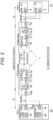
- Fig. 2 is a block diagram of a further embodied communication system of the communication system of Fig. 1 .
- the communication system in Figs. 1 and 2 is, for example, a camera video recognition system that is a part of an advanced driver assistance system (ADAS).
- ADAS advanced driver assistance system
- the communication device in Figs. 1 and 2 includes an ECU 4 and an SoC 5 that can operate as a Master 21, an image sensor 12 and a temperature sensor 14 that can operate as a Slave 22, a Master SerDes 7, and a Slave SerDes 13.
- the Master SerDes 7 and the Slave SerDes 13 are communicably connected to each other according to a predetermined communication standard (hereinafter referred to as a "communication standard X").
- a predetermined communication standard X include, but are not limited to, FPD-Link III, A-phy, ASA, and the like.
- Each of the Master SerDes 7 and the Slave SerDes 13 corresponds to a communication device according to the present embodiment.
- the Master SerDes 7 may be referred to as a SerDes 1
- the Slave SerDes 13 may be referred to as a SerDes 2.
- the Master 21 and the Master SerDes 7 are communicably connected to each other by, for example, inter-integrated circuit (I2C) communication.
- I2C inter-integrated circuit
- the communication between the Master 21 and the Master SerDes 7 is not limited to the I2C communication, and may be communication using general purpose input/output (GPIO), for example.
- GPIO general purpose input/output
- the Slave 22 and the Slave SerDes 13 are communicably connected to each other by, for example, the I2C communication.
- the communication between the Slave 22 and the Slave SerDes 13 is not limited to the I2C communication, and may be communication using GPIO, for example.
- a signal path on a transmission path 6 through which information is serially transmitted from the Slave SerDes 13 to the Master SerDes 7 is referred to as a downlink or a forward channel
- a signal path on the transmission path 6 through which information is serially transmitted from the Master SerDes 7 to the Slave SerDes 13 is referred to as an uplink or a reverse channel.
- the ECU 4 controls the entire communication system 3 and includes an I2C 4a.
- the ECU 4 receives an image signal from the Master SerDes 7 and performs the I2C communication with the Master SerDes 7 via the I2C 4a.
- the SoC 5 performs, for example, image recognition and video processing, and includes an I2C 5a.
- the SoC 5 receives an image signal from the Master SerDes 7 and performs the I2C communication with the Master SerDes 7 via the I2C 5a.
- the image sensor 12 captures an image, and includes an I2C 12a and a mem 19.
- the image sensor 12 outputs image data of the captured image to the Slave SerDes 13, and performs the I2C communication with the Slave SerDes 13 via the I2C 12a.
- the image sensor 12 may be referred to as a CMOS image sensor (CIS).
- the mem 19 can store pixel data captured by the image sensor 12, and can store data transmitted from the Master 21.
- the mem 19 may be referred to as a mem3.
- the temperature sensor 14 measures a temperature of an arbitrary object (for example, the image sensor 12), and includes an I2C 14a.
- the temperature sensor 14 performs the I2C communication with the Slave SerDes 13 via the I2C 14a, and transmits temperature data and the like regarding the measured temperature to the Slave SerDes 13.
- the Master SerDes 7 converts a format of a signal of an I2C protocol received from the Master 21 into a signal of a communication standard X protocol and transmits the signal to the Slave SerDes 13, and appropriately converts the format of the signal of the communication standard X protocol received from the Slave SerDes 13 to generate image data and an I2C protocol signal, and outputs the image data and the signal to the Master 21.
- the Master SerDes 7 includes a LINK 11, a forward receiver (Fw.Rx) 9, a reverse transmitter (Rv.Tx) 10, and an I2C 7a.
- the LINK 11 converts the format of the signal of the I2C protocol received from the Master 21 via the I2C 7a into a signal of the communication standard X protocol, and transmits the signal to the Slave SerDes 13 via the Rv.Tx 10. Furthermore, the LINK 11 generates image data from the signal of the communication standard X protocol received from the Slave SerDes 13 via the Fw.Rx 9 and transmits the image data to the Master 21, or generates a signal of the I2C protocol including information other than the image data and outputs the signal to the Master 21 via the I2C 7a.
- the Slave SerDes 13 converts the format of the signal of the I2C protocol and the image signal received from the Slave 22 into a signal of the communication standard X protocol and transmits the signal to the Master SerDes 7, and appropriately converts the format of the signal of the communication standard X protocol received from the Master SerDes 7 into a signal of the I2C protocol and outputs the signal to the Slave 22.
- the Slave SerDes 13 includes an I2C 13a, a LINK 17, a forward transmitter (Fw.Tx) 16, a reverse receiver (Rv.Rx) 15, and an I2C 13a.
- the LINK 17 converts the format of the signal of the I2C protocol signal and the image data received from the Slave 22 via the I2C 13a into a signal of the communication standard X protocol, and transmits the signal to the Master SerDes 7 via Fw.Tx 16. Furthermore, the LINK 17 converts the signal of the communication standard X protocol received from the Master SerDes 7 via the Rv.Rx 15 into a signal of the I2C standard, and transmits the signal to the Slave 22 via the I2C 13a. At this time, the following problems 1) and 2) may occur.
- the case means that an I2C operation section of the REMOTE I2C (sections other than SCL low on the REMOTE I2C side in Fig. 3 ) becomes long, which, in combination with a problem that the SCLLow section on the HOST I2C side becomes long, further increases the time required for completing the I2C communication.
- the communication system 3 in Figs. 1 and 2 provides a storage device (a mem 11a in Fig. 1 ) in the Master SerDes 7, and when the Master SerDes 7 receives 1 byte from the Master 21, the communication system 3 stores the 1 byte in the storage device, and returns the ACK signal or the NACK signal to the Master 21 instead of the Slave 22. Therefore, the Master 21 can shorten the SCL low period that extends.
- the Master 21 sets CLK_value (Data[0]) to be described below, and the Slave SerDes 13 performs the I2C communication with the Slave 22 at the frequency designated by CLK_value (Data[0]). Therefore, the Slave 22 and the Slave SerDes 13 can implement the I2C communication at the designated frequency.
- the LINK 11 of Fig. 2 includes an I2C Cmd Unit 8 and a mem 11a.
- the I2C Cmd Unit 8 stores table2 in a ROM (not illustrated), and the mem 11a stores table1.
- the mem 11a is a volatile memory. In the present specification, the mem 11a may be referred to as mem1.
- the LINK 11 Each time the LINK 11 receives 1 byte from the Master 21 via the I2C 7a, the LINK 11 writes the 1 byte to the table1 of the mem 11a, returns the ACK signal or the NACK signal to the Master 21 instead of the Slave 22, reads the table1 and transmits the table1 to the Slave SerDes 13 via the Rv.Tx 10 when a predetermined condition is satisfied (for example, when data is written to End of data).
- a predetermined condition for example, when data is written to End of data.
- the LINK 11 writes the signal received from the Slave SerDes 13 via Fw.Rx into the table1 of the mem 11a, and reads the table1 and performs the I2C communication with the Master 21 via the I2C 7a and simultaneously transmits the image data captured by the image sensor 12 received from the Slave SerDes 13 via the Fw.Rx 9 to the Master 21 when a predetermined condition is satisfied (for example, when data is written to End of data).
- the LINK 17 of Fig. 2 includes an I2C Cmd Unit 18 and a mem 17a.
- the I2C Cmd Unit 18 stores table2 in a ROM (not illustrated), and the mem 17a stores table3.
- the mem 17a may be referred to as mem2.
- the LINK 17 writes the signal received from the Master SerDes 7 via the Rv.Rx 15 to the table3 of the mem 17a, and reads the table3 and transmits the table3 to the Slave 22 via the I2C 13a when a predetermined condition is satisfied (for example, data is written to End of data).
- the LINK 17 writes the received data into the table3 of the mem 17a, and reads the table3 and transmits the table3 to the Master SerDes 7 via the Fw.Tx 16 when a predetermined condition is satisfied (for example, the data is written to End of data).
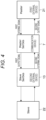
- Fig. 4 is an equivalent block diagram when the Master SerDes 7 performs the I2C communication between the Master 21 and the Slave SerDes 13 in the communication system 3 of Figs. 1 and 2 .
- the Master SerDes 7 is a communication device
- the Master 21 is a first external device
- the Slave SerDes 13 is a second external device.
- the communication device (Master SerDes 7) in Fig. 4 generates a first output signal on the basis of a first external signal from the first external device (Master 21) and outputs the first output signal to the second external device (Slave SerDes 13). Furthermore, the communication device (Master SerDes 7) generates a second output signal on the basis of a second external signal from the second external device (Slave SerDes 13) and outputs the second output signal to the first external device (Master 21).
- Fig. 5 is an equivalent block diagram when the Slave SerDes 13 performs the I2C communication between the Slave 22 and the Master SerDes 7 in the communication system 3 of Figs. 1 and 2 .
- the Slave SerDes 13 is the communication device
- the Slave 22 is the first external device
- the Master SerDes 7 is the second external device.
- the communication device (Slave SerDes 13) in Fig. 5 generates the first output signal on the basis of the first external signal from the first external device (Slave 22) and outputs the first output signal to the second external device (Master SerDes 7). Furthermore, the communication device (Slave SerDes 13) generates the second output signal on the basis of the second external signal from the second external device (Master SerDes 7) and outputs the second output signal to the first external device (Slave 22).
- Each of the first output signal and the second external signal in Figs. 4 and 5 includes command information Cmd_mode indicating content of a command transmitted from the first external device, final destination device identification information Slave_Adr for identifying a final destination device of data transmitted from the first external device, internal address information Sub_Adr of the final destination device, data length information Length of the data transmitted from the first external device, and data end position information End of Data transmitted from the first external device.
- Slave_Adr may be arranged next to Cmd_mode, Sub_Adr may be arranged next to Slave_Adr, and Length may be arranged next to Sub_Adr.
- Cmd_mode may include command format information Cmd_mode[2:0] that defines a command format on the communication standard X including a function to identify a Write command and a Read command. That is, Cmd_mode may include Cmd_mode[2:0] that defines a command format on a predetermined communication standard between the communication device and the second external device.
- the Cmd_mode may include at least Cmd_mode[0] - Cmd_mode[7], and data end determination condition information Cmd_mode[7] may specify a condition for end determination of data transmitted from the first external device.
- Each of the first output signal and the second external signal may further include communication frequency information CLK_value that specifies a communication frequency between the second external device and the final destination device.
- the first output signal and the second external signal may include a command obtained by converting the protocol of a command of the inter-integrated circuit (I2C) communication into a predetermined communication standard between the communication device and the second external device.
- I2C inter-integrated circuit
- the LINK 11 or 17 may transmit the ACK signal indicating an acknowledgement or the NACK signal indicating a negative acknowledgement to the first external device each time receiving each information unit constituting the first external signal from the first external device.
- the LINK 11 or 17 includes a storage unit that stores a signal corresponding to the first external signal and a signal corresponding to the second external signal.
- the LINK 11 or 17 may generate the first output signal after collectively performing protocol conversion for the first external signals received and stored in the storage unit when reception of the first external signals from the first external device is completed.
- the protocol conversion by the LINK 11 or 17 may be protocol conversion compatible with time division duplex (TDD).
- TDD time division duplex
- the LINK 11 or 17 When the LINK 11 or 17 transmits the first output signal to the second external device and receives information indicating that the processing for the first output signal is completed from the second external device, the LINK may store a signal indicating processing completion in the storage unit.
- the LINK 11 or 17 may release a storage area of the storage unit on the basis of a command from the first external device.
- the LINK 11 or 17 may output processing completion information for the second external signal transmitted from the second external device to the first external device in response to a request signal from the first external device, or may output an interrupt request flag for performing interrupt processing for the first external device to the first external device.
- the LINK 11 or 17 may receive the first external signal including output instruction information cmd_done instructing output of the first output signal and transmission end information P (STOP condition) indicating transmission end of the first external signal from the first external device.
- the LINK 11 or 17 may recognize that the first external signal transmitted from the first external device has ended when transmission end information P (STOP condition) indicating transmission end of the first external signal is received.
- the LINK 11 or 17 may recognize that the first external signal transmitted from the first external device has ended when the output instruction information instructing output of the first output signal and the transmission end information indicating transmission end of the first external signal are received regardless of the value of the data end determination condition information received thereafter.
- the LINK 11 or 17 may release the storage area of the storage unit after transmitting the first output signal to the second external device.
- the LINK 11 or 17 may perform at least one of outputting a signal obtained after performing the protocol conversion for the second output signal for the signal based on the second external signal stored in the storage unit to the first external device for each information unit, or receiving each information unit constituting the first external signal output from the first external device, a predetermined number of times or within a predetermined time.
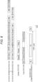
- Fig. 6 is a diagram illustrating an example of a frame structure of the signal of the communication standard X protocol transmitted and received between the Master SerDes 7 and the Slave SerDes 13.
- the frame structure of Fig. 6 includes a plurality of containers between a Sync pattern and a Parity.
- the Sync pattern is a signal pattern for synchronizing physical layers of the Master SerDes 7 and the Slave SerDes 13.
- the plurality of containers includes, for example, about two to one hundred containers.
- the number of containers included in the frame structure changes depending on a signal transmission state.
- the Parity is a bit or a bit string for error detection or error correction processing.
- the structure of the container includes a Header, a Payload, and a Parity.
- the Header includes address information indicating a transmission destination of the Payload, and the like.
- the Payload is a main part of a signal to be transmitted and received.
- the Payload includes operations, administration, maintenance (OAM) for SerDes control in addition to a video signal.
- the Parity is a bit or a bit string for Payload error detection or error correction processing.
- the Palyload includes information of CLK value, Cmd_mode, Slave Adr, length, data, and End of data.
- the CLK value is an operation clock of the Slave 22, that is, an SCL frequency used by the Slave SerDes 13 in the I2C communication with the Slave 22.
- Cmd_mode indicates content of a command transmitted from the Master 21.
- Slave Adr is address information for identifying the Slave 22.
- length is a length of data transmitted from the Master 21.
- End of data is an end position of data transmitted from the Master 21.
- Cmd_mode is extended to two bytes
- an upper one byte of Cmd_mode may be allocated to Cmd_ID.
- Cmd_ID is identification information for distinguishing and identifying a command transmitted from the Master 21.
- a signal ratio of a signal Rv from the Master 21 to the Slave 22 and a signal ratio of a signal Fw from the Slave 22 to the Master 21 within one TDD cycle can be changed by changing the number of containers included in each frame structure.
- the signal Rv and the signal Fw may have the same or different container sizes.
- the I2C communication is performed between the Master 21 and the Master SerDes 7, and the I2C communication is also performed between the Slave SerDes 13 and the Slave 22.
- the I2C communication it is possible to select either a first mode (also referred to as Byte I2C mode) of receiving the ACK signal/NAK signal each time transmitting information of a predetermined number of bytes (for example, one byte or two bytes in a case of not transmitting an error correction code, or two bytes or three bytes in a case of transmitting the error correction code), or a second mode (Bulk I2C mode) of receiving the ACK signal/NAK signal each time transmitting bulk information that is a bulk of information of a plurality of bytes.
- a first mode also referred to as Byte I2C mode
- Bulk I2C mode Bulk I2C mode
- the operation of receiving the ACK/NACK signal is repeated each time 1-byte data is transmitted, as illustrated in the timing chart of Fig. 8 .
- FDD frequency division duplexing
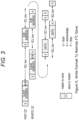
- Fig. 9A is a timing chart of the Bulk I2C mode in the TDD scheme
- Fig. 9B is a timing chart of the Byte I2C mode in the TDD scheme.
- the Master SerDes 7 transmits a signal including the ACK signal or the NACK signal to the Master 21 each time receiving a signal of a plurality of bytes transmitted from the Master 21 byte by byte as illustrated in Fig. 9A .
- the Master SerDes 7 collectively transmits the converted signals to the Slave SerDes 13.
- the Master SerDes 7 receives and retains the signal of the communication protocol X (first communication standard) including the ACK signal or the NACK signal from the Slave SerDes 13. Thereafter, the Master SerDes 7 converts the signal of the communication protocol X into a signal of the I2C protocol (second communication standard) and transmits the signal to the Master 21 in response to a readout request from the Master 21.
- first communication standard the signal of the communication protocol X
- the Master SerDes 7 converts the signal of the communication protocol X into a signal of the I2C protocol (second communication standard) and transmits the signal to the Master 21 in response to a readout request from the Master 21.
- the signal transmitted to the Slave SerDes 13 includes command information indicating content transmitted from the Master 21, and the signal transmitted to the Master 21 includes information transmitted from the Slave SerDes 13.
- the Slave SerDes 13 when receiving a signal of a plurality of bytes of the communication protocol X transmitted from the Master SerDes 7, the Slave SerDes 13 converts the received signal into a signal of the I2C protocol and transmits the converted signal to the Slave 22 byte by byte. Each time the converted signal is transmitted to the Slave 22 byte by byte, signals of the I2C protocol including the ACK signal or the NACK signal from the Slave 22 are received and retained. After the transmission of the signal from the Master SerDes 7 to the Slave 22 is completed, a signal of the communication protocol X corresponding to the retained signal is transmitted to the Master SerDes 7.
- the Master SerDes 7 converts a 1-byte signal transmitted from the Master 21 into a signal of the first communication standard in units of the 1-byte signal and transmits the converted signal to the Slave SerDes 13, then receives a signal of the first communication standard including the ACK signal indicating an acknowledgement or then NACK signal indicating a negative acknowledgement transmitted from the Slave SerDes 13, and converts the received signal into a signal of the second communication standard and transmits the signal to the Master 21.
- the Slave SerDes 13 when receiving a signal of the first communication standard transmitted from the Master SerDes 7, the Slave SerDes 13 converts the received signal into a signal of the second communication standard in units of the received signal and transmits the converted signal to the Slave 22, then receives a signal of the second communication standard including the ACK signal indicating an acknowledgement or the NACK signal indicating a negative acknowledgement transmitted from the Slave 22, and converts the received signal into a signal of the first communication standard and transmits the signal to the Master SerDes 7.
- Cmd_mode The information of Cmd_mode in the frame structure illustrated in Fig. 6 is different between the Bulk I2C mode and the Byte I2C mode.
- Cmd_mode may be referred to as command information.
- Cmd_mode is, for example, 1-byte information, and information of each bit is different between the Bulk I2C mode and the Byte I2C mode.
- Fig. 10A is a diagram illustrating an example of cmd_mode in the Bulk I2C mode.
- Bit [7] of cmd_mode in Fig. 10A is above-described selection of mode, and indicates the Byte I2C mode in the case of 1 and indicates the Bulk I2C mode in the case of 0.
- Bit [6] is a bit designating whether or not to perform retry at the time of receiving the NACK signal in the Slave-side I2C communication, and 1 indicates retry and 0 indicates no retry.
- Bit [5] is a bit indicating an operation of the Slave SerDes 13 when the Slave SerDes 13 receives the NACK signal during the access to the Slave 22.
- Bit [4] indicates a batch transmission mode of an I2C command. 1 indicates End of data and to perform transmission at the time of cmd_doen. 0 indicates that end determination is made for each End of data and transmission is performed. Bit [3] is selection of an I2C address mode on the Slave side. 1 indicates an address of a current location without an offset address, and 0 indicates the address of the current location with the offset address. Bit [2:0] is an I2C format type of the communication standard X. 111 indicates an error command format, 110 indicates a special command format, 10X indicates a reserve, 011 indicates a Read response format, 010 indicates an AC/NACK format, 001 indicates a Read command format, and 000 indicates a Write command format.
- Fig. 10B is a diagram illustrating an example of cmd_mode in the Byte I2C mode.
- Bit [7] of cmd_mode in Fig. 10B is the same as the bit [7] in Fig. 10A , and may be referred to as first information in the present specification.
- Bit [6:5] is selection of a clock mode, and may be referred to as second information in the present specification.
- the clock mode includes a mode in which node2 automatically generates a clock signal and a mode in which node1 calculates and provides notification of the number of cycles 9/8/1 of the used clock CLK of the node2 instead of the node2, where the Master SerDes 7 is the node1 and the Slave SerDes 13 is the node2.
- 11 indicates that the node2 generates nine clock signals including the ACK/NACK signal and data. 10 indicates that the node2 generates eight clock signals including data. 01 indicates that the node2 generates one clock signal including the ACK/NACK signal. 00 indicates that the node2 automatically generates 9/8/1 clock signals.
- Bit [4:0] is an I2C packet type that defines packetized I2C data.
- the bit [4] is information instructing whether or not data is data for Write or Read or other data, and may be referred to as third information in the present specification. 1 of the bit [4] indicates that a Write/Read data packet follows next. 0 of the bit [4] indicates that the Write/Read data packet is not present.
- the bit [3] is information indicating whether or not the NACK signal has been received, and may be referred to as fourth information in the present specification. 1 of the bit [3] indicates that the NACK signal has been received from the Slave 22 or the Master 21, and 0 indicates that the NACK signal has not been received.
- the bit [2] is information indicating whether or not the ACK signal has been received, and may be referred to as fifth information in the present specification. 1 of the bit [2] indicates that the ACK signal has been received from the Slave 22 or the Master 21, and 0 indicates that the ACK signal has not been received.
- the bit [1] is information indicating whether or not a STOP command is included, and may be referred to as sixth information in the present specification. 1 of the bit [1] indicates that the STOP command has been detected, and 0 indicates that the STOP command has not been detected.
- the bit [0] is information indicating whether or not a START/ReSTART command is included, and may be referred to as seventh information in the present specification. 1 of the bit [0] indicates that the START/ReSTART command has been detected, and 0 indicates that the START/ReSTART command has not been detected.
- cmd_mode illustrated in Figs. 10A and 10B is an example, and what information is allocated to each bit of cmd_mode is arbitrary. Furthermore, cmd_mode may have a byte length of 2 bytes or more.
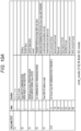
- Fig. 11A is a diagram illustrating a first example of the command format to be transmitted and received in the I2C communication when the Bulk I2C mode is selected.
- the Write command format includes clk_value, cmd_mode, Sl_adr, Sub_adrH, Sub_adrL, lengthH, lengthL, WDATA, and End of data.
- the Read command format is the same as the Write command format except that WDATA is not included.
- the ACK/NACK command format includes clk_value, cmd_mode, Master_adr, Sub_adrH, Sub_adrL, lengthH, lengthL, Sl_adr, ACK/NACK, and End of data.
- the Read response format is obtained by adding RDATA to the ACK/NACK command format.
- the special command format includes clk_value, cmd_mode, Cmd_done, and End of data.
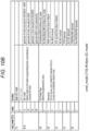
- Fig. 11B is a diagram illustrating a second example of the command format to be transmitted and received in the I2C communication when the Bulk I2C mode is selected.
- CRC that is an error correction code is added after End of Data at the end of each command format illustrated in Fig. 11A .
- an error command format that does not exist in the first example of Fig. 11A is newly added.
- the error command format includes clk_value, cmd_mode, End of data, and CRC. The error command format will be described below.
- Figs. 11A and 11B include End of Data (EoD) near the end of each command format, but the EoD can be omitted.
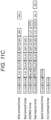
- Fig. 11C is a diagram illustrating a third example of the command format to be transmitted and received through the I2C communication when the Bulk I2C mode is selected, in which EoD is omitted from each format in Fig. 11A . Even if the information of EoD is used inside the Master SerDes 7 and the Slave SerDes 13, data end position can be calculated on the reception side from the information of cmd _mode, lengthH, and lengthL, even if there is no EoD in the communication format between the Master SerDes 7 and the Slave SerDes 22.
- EoD End of Data
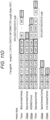
- Fig. 11D is a diagram for describing a method of calculating a position of End of Data in the third example of Fig. 11C .
- Each of the Read command format, the ACK/NACK format, the special command format, and the error command format has a fixed byte length. More specifically, the Read command format is 7 bytes, the ACK/NACK format is 9 bytes, the special command format is 3 bytes, and the error command format is 2 bytes. Therefore, even if there is no EnD, an end position of each format can be specified. Note that the ACK/NACK format is not necessarily fixed to 9 bytes. All ACKs/NACKs received during the I2C communication may be appended.
- Fig. 11E is a diagram illustrating a first example of a command format when the Byte I2C mode is selected. As illustrated in Fig. 11E , an I2C condition format or an I2C data format is selected when the Byte I2C mode is selected.
- the I2C condition format includes cmd_mode and CRC.
- the I2C command to be transmitted in the I2C condition format is START (S), ReSTART (Sr), STOP (P), and ACK/NACK.
- the I2C data format includes cmd_mode, Data, and CRC.
- the I2C command to be transmitted in the I2C data format is START (S), ReSTART (Sr), STOP (P), and ACK/NACK + data.
- clk _value or cmd_id may be added to the command format of Fig. 11E .
- Fig. 11F is a diagram illustrating a second example of the command format when the Byte I2C mode is selected. The second example in Fig. 11F illustrates an example in which clk _value and cmd_id are added immediately before cmd_mode in the first example in Fig. 11E . Whether or not to add CRC to the end of each format in the second example of Fig. 11F is arbitrary. The same similarly applies to the first example of Fig. 11E .
- Fig. 12 is a diagram illustrating types and bit strings of the I2C commands to be transmitted on the communication standard X protocol in the Bulk I2C mode.
- ACK is an acknowledgement, indicating that processing has been normally completed.
- NACK is a negative acknowledgement, indicating that the processing has not been normally ended.
- Repeated_start is a start flag indicating that the signal of the I2C protocol continues. Specifically, Repeated_start corresponds to Sr in a combined format of I2C illustrated in Fig. 7 .
- Sr is a flag issued before starting the next I2C communication in a case of starting the next I2C communication without ending the I2C communication (without issuing STOP condition (P)) after starting the I2C communication from the Master 21 to the Master SerDes 7 (after issuing START condition (S)).
- End of data in the I2C command transmitted on the communication standard X protocol indicates the P (STOP condition).
- Cmd_mode [4] 0 in the Bulk I2C mode
- the case indicates that the signal of the I2C protocol from S (START condition) to P (STOP condition) is transmitted to the Slave SerDes 13.
- cmd_done is information instructing transmission of one or more sets to the Slave SerDes 13, where signals of the I2C protocol from S (START condition) to P (STOP condition) is one set.
- Rsv_command in the I2C command to be transmitted on the communication standard X protocol is Reserved and is not defined at present.
- the data in the I2C command indicates data to be written to the Slave 22 or data read from the Slave 22.
- Fig. 12 illustrates an example in which the I2C command to be transmitted on the communication standard X protocol is expressed by 8 bits, but the present embodiment is not limited thereto, and the I2C command may be expressed by 9 bits or more.
- the I2C command may be expressed by 9 bits or more.
- one bit on the MSB side is set to "0" in a case where the signal of the I2C protocol is "data”
- one bit on the MSB side is set to "1" in a case where the signal of the I2C protocol is other than "data” so that it is possible to easily determine whether or not the signal of the I2C protocol is "data" or other than "data”.
- Figs. 13A and 13B are diagrams illustrating setting examples of cmd-mode in a case where the Slave SerDes 13 that is the node2 automatically generates a clock CLK.
- Fig. 13A illustrates a setting example of cmd-mode in a case of transmitting condition information and an instruction for the Slave SerDes 13 to automatically generate the number of clocks CLK in the Byte I2C mode.
- cmd_mode of 1-byte data is set to 8'b1000_0001.
- Each bit of cmd_mode is set according to Fig. 10B .
- the bit [4] 0 indicates that no data is included.
- the bit [3] 0 indicates that the NACK signal is not received.
- the bit [2] 0 indicates that the ACK signal is not received.
- the bit [1] 0 indicates that the STOP command is not included.
- the bit [0] 1 indicates that the START command is included.
- Fig. 13B illustrates a setting example of the cmd-mode in a case of transmitting data and an instruction for the Slave SerDes 13 to automatically generate the number of clocks CLK in the Byte I2C mode.
- cmd_mode is set to 8'b1001_0000.
- the number of bytes of the signal transmitted from the Master SerDes 7 to the Slave SerDes 13 in the Byte I2C mode is 2 bytes or 3 bytes excluding the clock frequency information clk_value and the error correction code CRC.
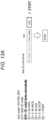
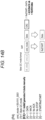
- Figs. 14A and 14B are diagrams illustrating examples in which the Slave SerDes 13 that is the node2 manually generates the clock CLK on the basis of the number of cycles instructed by the Master SerDes 7 that is the node1.
- Fig. 14A illustrates a setting example 1 of the cmd-mode in a case of transmitting condition information, data, and designation of the number of clocks CLK generated by the Slave SerDes in the Byte I2C mode.
- Fig. 14B illustrates a setting example 2 of the cmd-mode in a case of transmitting condition information, data, and designation of the number of clocks CLK generated by the Slave SerDes in the Byte I2C mode.
- cmd_mode in Fig.
- the bit [6:5] 01 of cmd_mode indicates that the node2 instructs generation of the clock CLK of one cycle.
- the bit [4] 1 indicates that data is included.
- the other bits are similar to those in Fig. 13A .
- cmd_mode in Fig. 14B is set to 8'b1111_0001.
- the other bits are similar to those in Fig. 14A .
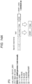
- Fig. 15A illustrates an example of transmitting an ACK and data in the Byte I2C mode.
- Fig. 15B illustrates an example of transmitting a NACK and a STOP command in the Byte I2C mode.
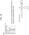
- Fig. 16 is a diagram illustrating a setting example of the cmd_mode in a case where an error occurs.
- cmd_mode in Fig. 16 is set to 8'b1xx0_1111.
- the bit [6:5] xx of cmd_mode indicates don't care.
- Bit [3:0] 1111 is set. As described above, when all the lower four bits of cmd_mode become 1, it indicates that an error has occurred during execution of the Byte I2C mode.
- Fig. 17 is a state transition diagram of the Master SerDes 7 that is the node1 and the Slave SerDes 13 that is the node2.
- the states of both the node1 and node2 transition on the basis of the state transition diagram illustrated in Fig. 17 .
- the state transition diagram of Fig. 17 illustrates the state transition during the Byte I2C mode of Fig. 9B . Note that, during the Bulk I2C mode in Fig. 9A , transmission and reception are collectively performed from S (START condition) to P (STOP condition), and thus it is not necessary to consider the state transition.
- S START condition
- P STOP condition
- the node1 and node2 transition to an initial state init when power is ON (state S1).
- a START/ReSTART (S/Sr) command of the I2C protocol is received from the Master 21 in the initial state init
- the node1 transitions to a START state ST (state S2).
- the node1 converts the S/Sr (START/ReSTART) command of the I2C protocol received in the state S1 into a packet of the communication standard X in Fig. 13A and transmits the packet to the node2.
- the node2 transitions to the Start state ST and transmits the S/Sr (START/ReSTART) command converted into the I2C protocol to the Slave 22.
- the node1 When receiving data D from the Master 21 in the Start state ST, the node1 determines whether or not the data is a Slave address (state S3). In a case where the data is not a Slave address, the node1 returns to the state S1. In a case where the data is a Slave address, the node1 transitions to a Slave address state Sl_Addr (state S4). In the Slave address state Sl_Addr, the node1 instructs the Master 21 to perform clock stretching. The clock stretching means holding the clock from the Master 21 at a low level. During a clock stretching period, the Master 21 cannot transmit new information to the node1.
- the node1 converts the Slave address of the I2C protocol into a packet of the communication standard X and transmits the packet to the node2.
- the node2 transitions to a Slave address state S1_Addr and transmits the Slave address converted into the I2C protocol to the Slave 22.
- the node2 transitions to a Write state W, converts the ACK/NACK signal into the protocol of the communication standard X, and transmits the converted ACK/NACK signal to the node1.
- the node1 When receiving the ACK/NACK signal from the node2 in the Slave address state Sl_Addr, the node1 transitions to the Write state W (state S5). In the Write state W, the node1 instructs the Master 21 to release the clock stretching, and converts the ACK/NACK signal from the node2 into the I2C protocol and transmits the ACK/NACK signal to the Master 21. When receiving the data D from the Master 21 in the Write state W, the node1 transitions to a Write data state WD (state S6). In this state, when returning the ACK/NACK signal to the Master 21, the state returns to the Write state W.
- the node1 When receiving the P (STOP) command from the Master 21 in the Write state W, the node1 transitions to an End state End (state S7).
- the End state End when the node1 converts the P (STOP) command of the I2C protocol into a packet of the communication protocol X, and transmits the packet to the node2, the state returns to the initial state init.
- the node2 When receiving ACK or NACK from the Slave 22 when having received the Slave address including a Read bit and having transitioned to the Slave address state Sl_Addr in state S4, the node2 transitions to a Read state R (state S8). Thereafter, the node2 converts the ACK or NACK of the I2C protocol into a packet of the communication protocol X and transmits the packet to the node1.
- the state transitions to a Read data state RD (state S9).
- the node2 converts Read data into a packet of the I2C protocol of the communication protocol X and transmits the packet to the node1.
- the node1 When receiving an ACK/NACK packet from the node 2, the node1 transitions to the Read state R and transmits the ACK or NACK to the Master 21. Thereafter, when receiving a Read data packet, the node1 transitions to the Read data state RD and transmits the Read data the Master 21.
- the ACK/NACK signal In a case where the ACK/NACK signal is not received within a time limit in the Read data state RD, it becomes timeout and the state transitions to a data error state (state S10). Similarly, also in a case where the data D from the Slave is not received within a time limit in the Read state R, it becomes timeout and the state transitions to the data error state of the state S10. When a dummy data signal is returned to the Master 21 in the data error state, the state returns to the Read state R of the state S8.
- the state transitions to an ACK error state a_err (state S11).
- the state transitions to the ACK error state a_err of the state S11.
- predetermined error processing is performed in the ACK error state a_err, the state returns to the state S1.
- the state transition when the Master SerDes 7 performs write in the Byte I2C mode is summarized as follows.
- LINK 11 in the Master SerDes 7 transitions to the Start state ST (first state).
- the LINK 11 converts the Start Condition into a signal of the communication protocol X (first communication standard) and transmits the signal to the Slave SerDes 13.
- the LINK 11 transitions to the Slave address state S1_Addr (second state) and holds a clock from the Master 21 to a low level.
- the LINK 11 converts the signal including the address information into a signal of the communication protocol X and transmits the signal to the Slave SerDes 13. Thereafter, when receiving a signal including the ACK signal or the NACK signal from the Slave SerDes 13 while being in the Slave address state S1_Addr, the LINK 11 recognizes write in a case where a specific bit of the signal including the address information is a first bit value and transitions to the Write state W (third state).
- the LINK 11 converts the signal including the ACK signal or the NACK signal received from the Slave SerDes 13 into a signal of the I2C protocol (second communication standard) and transmits the signal to the Master 21, and then releases the hold of the low level of the clock from the Master 21.
- the LINK 11 transitions to the Write data state WD (fourth state).
- the Write data state WD the LINK 11 converts the received signal into a signal of the communication protocol X and transmits the signal to the Slave SerDes 13.
- the LINK 11 transitions to the Write state W, converts the received ACK/NACK signal into a signal of the I2C protocol, and transmits the signal to the Master 21.
- the LINK 11 transitions to the ACK error state a_err (fifth state) and performs error processing in the ACK error state a_err.
- the state transition when the Master SerDes 7 performs readout in the Byte I2C mode is summarized as follows.
- the LINK 11 in the Master SerDes 7 transitions to the Start state ST.
- the LINK 11 converts the received signal including the Start Condition or ReStart Condition into a signal of the communication protocol X and transmits the signal to the Slave SerDes 13.
- the LINK 11 transitions to the Slave address state Sl_Addr and holds a clock from the Master 21 to a low level.
- the LINK 11 converts the signal including the address information into a signal of the communication protocol X and transmits the signal to the Slave SerDes 13. Thereafter, when receiving the signal including the ACK signal or the NACK signal from the Slave SerDes 13 while being in the Slave address state S1_Addr, the LINK 11 recognizes readout in a case where a specific bit of the signal including the address information is a second bit value and transitions to the Read state R (sixth state).
- the LINK 11 converts the signal including the ACK signal or the NACK signal received from the Slave SerDes 13 into a signal of the I2C protocol and transmits the signal to the Master 21, and then releases the hold of the low level of the clock from the Master 21.
- the LINK 11 transitions to the Read data state RD (seventh state). In the Read data state RD, the LINK 11 converts the received signal into a signal of the I2C protocol and transmits the signal to the Master 21. Thereafter, when receiving the signal including the ACK signal or the NACK signal from the Master 21 while being in the Read data state RD, the LINK 11 transitions to the Read state R, and converts the received signal into a signal of the communication protocol X and transmits the signal to the Slave SerDes 13.
- the LINK 11 transitions to the data error state d_err (eighth state). Furthermore, in a case of not receiving the ACK signal or the NACK signal within a predetermined period from the Master 21 while being in the Read data state RD, the LINK 11 transitions to the data error state d_err.
- the LINK 11 avoids deadlock of the entire system including the communication device, the Master 21, and the Slave SerDes 13 by performing the error processing in the data error state d_err.
- the LINK 11 in the Master SerDes 7 holds received signals from when receiving the signal including the Start Condition from the Master 21 to when receiving the signal including the Stop Condition, and transmits the signal including the ACK signal or the NACK signal to the Master 21 for each byte of the received signal.
- the LINK 11 converts the received signal into a signal of the communication protocol X and transmits the converted signal to the Slave SerDes 13.
- the LINK 11 receives and holds, from the Slave SerDes 13, the signal including the ACK signal or the NACK signal from the Slave 22, and then converts the signal from the Slave SerDes 13 into a signal of the I2C protocol and transmits the signal to the Master 21 in response to a readout request from the Master 21.
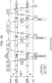
- Fig. 18 is a timing chart of a basic Write model (hereinafter referred to as Write operation 1) in which the Slave SerDes automatically generates the number of clocks CLK in the Byte I2C mode.
- the node2 can transmit Write data to the Slave 22 or receive the ACK signal from the Slave 22 by using the clock CLK.
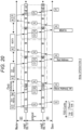
- Fig. 19 is a timing chart of a Write operation 2 that is a modification of the Write operation 1 of Fig. 18 .
- the START command is transmitted to the node2 when the node1 is in the START state St, but in the Write operation 2, the START command and the data D are collectively transmitted to the node2 when the node1 is in the Slave address state Sl_Addr.
- transactions of the communication protocol X can be reduced as compared with the Write operation 1 of Fig. 18 .
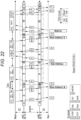
- Fig. 20 is a timing chart of a basic Write operation 3 for designating the number of clocks CLK in the Byte I2C mode.
- the node1 designates information of the number of cycles of the clock CLK used by the node2 in cmd_mode. In this case, one cycle is designated.
- the node2 receives the ACK signal from the Slave 22 using the clock CLK.
- Fig. 20 is adopted in a case where, for example, processing performance of the node2 is low.
- the node1 calculates the necessary number of cycles of the clock CLK instead of the node2.
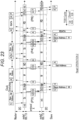
- Fig. 21 is a timing chart of a Write operation 4 that is a modification of the Write operation 3 of Fig. 20 .
- the START command is transmitted to the node2 when the node1 is in the START state St, but in the Write operation 4, the START command and the data D are collectively transmitted to the node2 when the node1 is in the Slave address state Sl_Addr.
- transactions of the specific protocol X can be reduced as compared with the Write operation 3.
- Fig. 22 is a timing chart of a basic Read model (hereinafter referred to as Read operation 1) in which the Slave SerDes automatically generates the number of clocks CLK in the Byte I2C mode.
- the node2 receives the ACK signal from the Slave 22 or receives the RDATA and transmits the RDATA to the node1, using the clock CLK generated by the node2 itself.
- the Slave address and the offset address are transmitted to the Slave 22 by a Write command, and then, the same Slave address and Read command as those of the previous time are transmitted.
- Fig. 23 is a timing chart of a Read operation 2 that is a modification of the Read operation 1 of Fig. 22 .
- the node1 designates information on the number of cycles of the clock CLK used by the node2 in cmd_mode.
- the node2 receives the ACK signal from the Slave 22 using the clock CLK.
- the node2 receives the ACK and RDATA signals from the Slave 22 using the clocks CLK.
- the node1 calculates and provides notification of the number of cycles of the clock CLK used in the node2.
- Fig. 24 is a timing chart of a Read operation 3 in a case of absence of Sub Address. Unlike the Read operations 1 and 2, the Read operation 3 illustrates an example in which no offset address exists after the Slave address.
- the Slave address is first transmitted by the Write command, but in the Read operation 3, the Slave address is transmitted by the Read command from the beginning.
- the node2 transmits the Slave address to the Slave 22
- the node2 receives the ACK signal and the RDATA transmitted from the Slave 22 and transmits the ACK signal and the RDATA to the node1.
- the node1 transmits the ACK signal and the RDATA from the node2 to the Master 21.
- cmd_mode indicated as C8 in Fig.
- the clock CLK is used for the node2 to receive RDATA from the Slave 22.
- Fig. 25 is a timing chart of an Err operation 1 in the Byte I2C mode.
- the Err operation 1 is performed in a case where the ACK/NACK signal from the Slave 22 does not arrive within a time limit.
- the ACK/NACK signal does not reach the node2 from the Slave 22, it becomes timeout and the node1 and the node2 transition to an ACK_err state a_err due, perform the error processing, and then return to the initial state init.
- the node1 returns the NACK signal to the Master 21 and transfers an err packet to the node2.
- the node1 may register that the node1 is in the ACK_err state a_err in an err register.
- Fig. 26 is a timing chart of an Err operation 2 in the Byte I2C mode.
- the Err operation 2 is performed in a case where the RDATA from the Slave 22 does not arrive or in a case where a part of the RDATA is insufficient.
- the RDATA does not arrive from the Slave 22 to the node2 within a time limit, or in the case where a part of the RDATA is insufficient, it becomes timeout and the node1 and the node2 transition to a data_err state d_err.
- the node1 returns dummy RDATA to the Master 21 and transfers the err packet to the node2.
- the node1 may register the data_err state d_err in the err register.
- the Master 21 can grasp that the RDATA has arrived after the timeout, it is possible to determine whether or not the RDATA after the timeout is dummy data or normal data by reading the err register of the node1 as necessary.
- the Master 21 When performing Random Write to the Slave 22, the Master 21 first transmits a command set to the Master SerDes 7 by I2C communication.
- the protocol of the I2C communication at the time of Random Write is illustrated in Fig. 7 described above, and the Master 21 transmits the command set to the Master SerDes 7 in accordance with the protocol.
- Fig. 27 is a diagram illustrating signals transmitted and received between the Master 21 and the Master SerDes 7 in a case where the Random Write is performed from the Master 21 to the Slave 22 in the Bulk I2C mode.
- the signal of the I2C protocol from the Master 21 to the Master SerDes 7 is referred to as M I2C protocol. As illustrated in Fig.
- the M I2C protocol includes S (START condition), SerDes1 St_adr, W, mem1 Sub_adr, mem1 Sub_adr, I2C setting CLK, Cmd _mode, final target Slave adr, final target Sub adrH, final target Sub adrL, Data lengthH, Data lengthL, Data ⁇ 2, and P (STOP condition). Details of these pieces of information will be described below.
- Fig. 28 is a table illustrating an example of data saved in table1 in mem1 in the Bulk I2C mode.
- CLK_value that is a setting value of an I2C setting clock CLK is stored in an address of mem1 indicated by Sub_Adr transmitted by the M I2C protocol, and thereafter, data transmitted by the M I2C protocol is stored in an incremented address of mem1.
- the CLK_value is 1-byte information indicating the SCL frequency as described above, and the Slave 22 performs the I2C communication with the Slave SerDes 13 at the operation frequency designated by CLK_value.
- Cmd_mode of Sub_Adr [1] is 1-byte information indicating content of an instruction received by the Master SerDes 7 from the Master 21.
- Slave Adr of Sub_Adr [2] in table1 of Fig. 28 is 1-byte information indicating the address (for example, 0 ⁇ 02 in the case of the image sensor 12) of the Slave 22 to be written or read.
- Sub_adrH of Sub_Adr [3] is upper 1-byte information of an address indicating which Sub_adr of mem 19 (mem 3) in the image sensor 12 is to be accessed or which Sub_adr of mem 20 in the temperature sensor 14 is to be accessed.
- Sub_adrL of Sub_Adr [4] is lower 1-byte information of an address indicating which Sub_adr of mem 19 (mem 3) in the image sensor 12 is to be accessed or which Sub_adr of mem 20 in the temperature sensor 14 is to be accessed.
- LengthH of Sub_Adr [5] is upper 1-byte information of a data length of WDATA (Data [N-2:7]).
- LengthL of Sub_Adr [6] is lower 1-byte information of the data length of WDATA (Data [N-2:7]).
- WDATA of Sub_Adr [N-2:7] is data to be written to the Slave 22.
- One byte of data is stored for each bit of Sub_Adr.
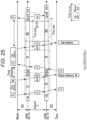
- Fig. 29 is a diagram following Fig. 27 and illustrating processing of transmitting a Random Write Command from the Master SerDes 7 to the Slave SerDes 13 in the Bulk I2C mode according to the communication standard X.
- the I2C protocol and mem1 (Save I2C command Packet) (steps S1 and S2) in Fig. 29 are the same as those described in Fig. 27 .
- the Master SerDes 7 reads data in table1 in Fig. 28 , performs protocol conversion for the data into a signal of the communication standard X protocol, and transmits the signal to the Slave SerDes 13 through a Packetized I2C on PHY (depend on the each PHY specification) forward channel (step S3).
- the Slave SerDes 13 extracts the I2C command packet from the received signal of the communication standard X protocol, and writes the I2C command packet into table3 in mem2. In Fig. 29 , this is called mem2 (Save I2C command Packet) (step S4).
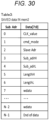
- Fig. 30 is a diagram illustrating an example of table3 in mem2 at the time of a Random Write operation in the Bulk I2C mode. Information having the same content as table1 in Fig. 28 is written to table3.
- the Slave SerDes 13 performs protocol conversion for received data of Reverse link, and restores original saved data of mem1 in mem2.
- the Slave SerDes 13 determines restoration end of the I2C command packet in the restoration of the End of data.
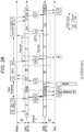
- Figs. 31 to 32 are diagrams following Fig. 29 and illustrating processing of transmitting data from the Slave SerDes 13 to the Slave 22 by the I2C communication.
- mem2 Save I2C command Packet
- step S4 in Figs. 31 and 32 has been described with reference to Fig. 29 .
- Fig. 31 illustrates processing in which the Slave SerDes 13 and the Slave 22 transmit and receive data in the I2C communication in the Bulk I2C mode.
- the Slave SerDes 13 reads the table3, converts the format into a signal of the I2C protocol, and transmits the signal to the Slave 22 via the I2C 13a in the M I2C protocol (step S5).
- (data)Sl_adr(0 ⁇ 02) indicates that "0 ⁇ 02" is designated as the above-described Sl_adr. Since "0 ⁇ 02", the image sensor 12 has been selected.
- (data)Sub_adrH(0 ⁇ 00) indicates that "0 ⁇ 00" is designated as a high-order bit of the address of mem3 (the target to be finally accessed) in the image sensor 12.
- (data)Sub_adrL(0 ⁇ 00) indicates that "0 ⁇ 00” is designated as a low-order bit of the address of mem3 (the target to be finally accessed) in the image sensor 12.
- (data)WDATA ⁇ 2 indicates data of 16 bytes.
- the Slave 22 sequentially returns the ACK signal indicating that the signal has been normally received to the Slave SerDes 13 in the S I2C protocol (step S5).
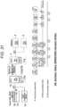
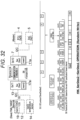
- Fig. 32 is a diagram following Fig. 31 and illustrating processing of performing a reply to the Random Write Command from the Slave SerDes 13 to the Master SerDes 7 with the communication protocol X in the Bulk I2C mode.
- the S I2C protocol (step S5) in Fig. 32 has been described with reference to Fig. 31 .
- the Slave SerDes 13 performs protocol conversion for an I2C communication result with the Slave 22 into a signal of the communication standard X protocol, and transmits the signal to the Master SerDes 7 through the Packetized I2C on PHY (depend on the each PHY specification) forward channel (step S6).
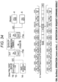
- Fig. 34 is a diagram following Fig. 32 and illustrating the operation of the Master SerDes 7 in the Bulk I2C mode.
- the Packetized I2C on PHY (depend on the each PHY specification) forward channel (step S6) in Fig. 34 has been described with reference to Fig. 32 .
- the Master SerDes 7 extracts the I2C command packet from the signal of the communication standard X protocol received from the Slave SerDes 13, and writes the I2C command packet in N to N+9 of Sub_Adr in table1 in mem1.
- Fig. 35 is a diagram illustrating table1 in mem1 after reception of reply data from the Slave SerDes to the Random Write Command in the Bulk I2C mode.
- the I2C command packet generated by the I2C Cmd Unit in the Slave SerDes 13 in Fig. 32 is saved in sub_Adr N to N+6 and N+9 in table1.
- sub_Adr N+7 and N+8 in table1 in Fig. 35 have content obtained by reading and transferring Slave adr of sub_Adr (2) and ACK or NACK of sub_Adr (N) in mem2.
- Fig. 36 is a diagram illustrating processing in a case where the Master 21 performs polling for the Master SerDes 7 for the Random Write Command in the Bulk I2C mode and reads an execution result.
- the Master 21 polls a request command result to the Master SerDes 7 in the M I2C protocol (step S7).
- End of Data (0 ⁇ 9F) and ACK (0 ⁇ 81) as a result thereof can be read.
- polling is determined by reading 1 byte and seeing the result of End of Data, and reading ACK or NACK by reading 1 byte again.
- NACK the Master 21 can check whether or not the corresponding Slave 22 has transmitted NACK by reading Slave adr of Sub_adr (N+7).
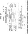
- Fig. 37 is a diagram illustrating transmission of a signal for releasing the storage area of mem1 from the Master 21 to the Master SerDes 7 as Random Write operation termination processing in the Bulk I2C mode.
- Fig. 38 is a diagram illustrating saved data in mem1 before the storage area for the Random Write Command is released.
- this Clear is written to the Master SerDes 7, the memory area of table1 in mem1 is released.
- the Master SerDes 7 releases the used storage area of mem1 as termination processing of the request command.
- the storage area of mem1 may be released according to a write command for initializing the memory area used by the Master 21.
- Figs. 39 to 41 are diagrams illustrating an I2C command batch transmission operation.
- Block b3 indicates the end of the batch operation by cmd_done and P (STOP condition).
- the Master 21 issues a command requesting the I2C communication with the Slave 22 to the Master SerDes 7 in the M I2C protocol (step S11).
- the Master SerDes 7 returns ACK at its own timing according to the S I2C protocol (step S11).
- the Random Read operation is substantially different from the Random Write operation in the following points.
- the Master 21 writes a Read request to the Master SerDes 7 ( Figs. 42 to 43 ), and the Master SerDes 7 writes the Read request in the Slave SerDes 13 ( Figs. 44 to 45 ).
- Fig. 42 illustrates a transmission procedure of the I2C command packet from the Master 21 to the Master SerDes 7 in the Bulk I2C mode.
- processing of the M I2C protocol is performed.
- the Master 21 issues, to the Master SerDes 7, a command to request the I2C communication with the Slave 22.
- the command set transmitted from the Master 21 includes SerDes1 St_adr, mem1 Sub_adr, mem1 Sub_adr, I2C setting CLK, Cmd_mode, final target Slave adr, final target Sub_adrH, final target Sub_adr, Data lengthH, Data lengthL, and P (STOP condition).
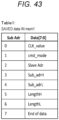
- Fig. 43 is a diagram illustrating saved data of table1 in mem1 at the time of the Random Read operation in the Bulk I2C mode. As illustrated in Fig. 43 , (data) CLK_value, (data) Cmd _mode, (data) Sl_adr, (data) Sub_adrH, (data) Sub_adrL, (data) length, (data) lengthL, and End of data are stored in mem1.
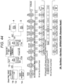
- Fig. 44 is a diagram following Fig. 42 and illustrating processing of transmitting the Random Read command from the Master SerDes 7 to the Slave SerDes 13 with the communication protocol X in the Bulk I2C mode.
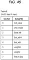
- Fig. 45 is a table illustrating an example of the saved data in mem2 at the time of the Random Read operation in the Bulk I2C mode.
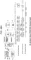
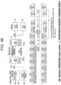
- Fig. 46A is a diagram following Fig. 44 and illustrating processing of transmitting a random read command from the Slave SerDes 13 to the Slave 22 in the Bulk I2C mode.
- the Slave SerDes 13 transmits the I2C command packet to the Slave 22 according to the M I2C protocol (step S25).
- the Slave 22 returns the ACK signal to the Slave SerDes 13 according to the S I2C protocol for each received information unit, and sequentially transmits RDATA to the Slave SerDes 13 from the address designated by Sub_adrH and Sub_adrL.
- Fig. 47 is a diagram illustrating saved data of table3 in mem2 after the Random Read operation in the Bulk I2C mode. As illustrated in Fig. 47 , the Slave SerDes 13 transmits the ACK signal indicating that RDATA has been received to the Slave 22 for each byte, and stores the RDATA from the Slave 22 in mem2.
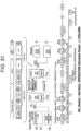
- Fig. 48 is a diagram following Fig. 46 and illustrating processing of returning the Read command from the Slave SerDes 13 to the Master SerDes 7 in the Bulk I2C mode according to the communication standard X.
- the Slave SerDes 13 transmits the RDATA via the Packetized I2C on PHY (depend on the each PHY specification) forward channel (step S26). More specifically, the Slave SerDes 13 converts the I2C communication result (RDATA, ACK) with the Slave 22 + End of data, and transmits a conversion result to the Master SerDes 7 in a forward link.
- Fig. 47 illustrates saved data of table3 in mem2 after the Random Read operation.
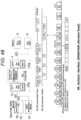
- Fig. 49 is a diagram following Fig. 48 and illustrating processing of the Master SerDes 7 when a reply from the Slave SerDes 13 to the Random Read Command is received in the Bulk I2C mode.
- the Master SerDes 7 performs the protocol conversion for the received data of the forward link, and saves the received data including the I2C communication result (ACK/NACK) with the Slave 22 in mem1.
- Fig. 50 is a diagram illustrating an example of data in mem1 after reception of reply data from the Slave SerDes 13 to the Random Read Command in the Bulk I2C mode.
- Fig. 51 is a diagram illustrating processing in a case where the Master 21 performs polling for the Master SerDes 7 for the Random Read Command in the Bulk I2C mode and reads an execution result.
- the Master 21 polls a request command result to the Master SerDes 7 in the M I2C protocol (step S27).
- the Master 21 performs polling at its own timing without waiting for ACK on the Slave 22 side, and the Master SerDes 7 returns ACK or RDATA as a polling result to the Master 21 (step S27).
- the End of data (0 ⁇ 9F) and the resulting ACK (0 ⁇ 81) can be read. If the readout result of End of data is other than 0 ⁇ 9F, polling is continued. In the present example, polling determination is performed by seeing the result of End of data by reading 1 byte, and RDATA (16 bytes) + ACK/NACK is read by reading 17 bytes again. However, it may also be possible to read 18 bytes at a time and determine the polling result and the I2C communication result to the Slave 22. In a case where the result is NACK, the Master 21 can confirm whether or not the NACK is from the Slave 22 by reading Slave adr of Sub_Adr (15).
- Fig. 52 is a diagram illustrating an example of saved data of table1 in mem1 before a storage area for the Random Read Command is released in the Bulk I2C mode.
- Fig. 46A the processing in which the Slave SerDes 13 performs random read for the Slave 22 has been described.
- random read is necessarily performed when the mem3 in the Slave 22 is accessed for the first time, but at and after the second time, current read may be performed.
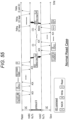
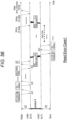
- Fig. 55 is a timing chart of the Read operation in the normal state of the Bulk I2C mode
- Fig. 56 is a timing chart in a case where an error occurs during Read in the Bulk I2C mode (hereinafter Read error case 1).
- the node2 transmits the Slave address and the offset address to the Slave 22, then receives the RDATA from the Slave 22, and transmits the RDATA to the node1.
- Fig. 56 illustrates an example in which the ACK/NACK signal does not arrive from the Slave 22 within a restricted period after the node2 transmits the offset address to the Slave 22.
- the node2 forcibly terminates the communication with the Slave 22 when it becomes timeout, transmits the error command format to the node1, and performs initialization processing.
- the Master 21 determines that an error has occurred during the I2C communication by reading the error command format received by the node1.
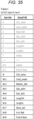
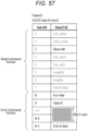
- Fig. 57 is a diagram illustrating saved data of table3 in mem2 when the Slave SerDes 13 that is the node2 in the Bulk I2C mode transmits the error command format.
- the value of the Read command format of SubAdr [0:7] is the same as that of table3 in Fig. 45 .
- SubAdr [8:N-1] in table3 in Fig. 45 has the Read response format
- SubAdr [8:N-1] in Fig. 57 has the error command format.
- RDATA is written in SubAdr [10:N-2] of Fig. 45
- SubAdr [10:N-2] of Fig. 57 is don't care.
- End of Data of the error command format is written in SubAdr [N-1] in Fig. 57 .
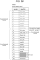
- Fig. 58 is a diagram illustrating saved data of table1 in mem1 when the Master SerDes 7 that is the node1 in the Bulk I2C mode transmits the error command format.
- the value of the Read command format of SubAdr [0:7] is the same.
- SubAdr [8:N-1] in table1 of Fig. 50 has the Read response format
- SubAdr [8:N-1] in Fig. 58 has the error command format.
- RDATA is written in SubAdr [N-3:N-2] in Fig. 45
- SubAdr [N-3:N-2] in Fig. 58 is don't care. Since End of Data in the error command format is written in SubAdr [N-] in Fig. 58 , the Master 21 can perform similar polling processing at the time of normal operation and error operation.
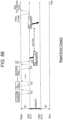
- Fig. 59 is a timing chart in a case where an error has occurred during Read in the Bulk I2C mode (hereinafter, Read error case 2).
- Fig. 59 illustrates a case where the Read command format cannot be transmitted from the node1 to the node2. Since the node1 cannot transmit the Read command format to the node2 within the restricted period, the node1 transmits the error command format to the node2, providing notification that an error has occurred.
- the Master 21 determines that an error has occurred during the I2C communication by reading the error command format of the node1. When receiving the error command format, the node2 performs the initialization processing as necessary.
- Fig. 60 is a diagram illustrating saved data of table1 in mem1 of the node1 (Master SerDes 7) in the Read error case 2.
- the Read command format of SubAdr [0:7] is the same as the Read command format of SubAdr [0:7] in table1 of Fig. 50 .
- SubAdr [8:N-1] of Fig. 50 has the Read response format
- SubAdr [8:N-1] of Fig. 60 has the error command format.
- SubAdr [10:N-2] in the error command format is don't care, and End of Data of the error command format is written in SubAdr [N-1]. Therefore, the Master 21 can perform similar polling processing in the normal state and in the error state.
- Fig. 61 is a diagram illustrating saved data of table1 in mem1 included in the node1 in a Write error case.
- the Write command format of SubAdr [0:N-1] is the same as the Write command format of SubAdr [0:N-1] in table1 of Fig. 35 .
- SubAdr [N:N+9] of Fig. 35 has the ACK/NACK format
- SubAdr [N:N+9] of Fig. 61 has the error command format.
- SubAdr [N+2:N+8] in the error command format is don't care, and End of Data of the error command format is written in SubAdr [N+9]. Therefore, the Master 21 can perform similar polling processing in the normal state and in the error state.
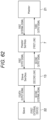
- Fig. 62 is an equivalent block diagram of the communication system 3 according to the present embodiment.
- the communication system 3 in Fig. 62 provides the Master SerDes 7 and the Slave SerDes 13 between the Master 21 and the Slave 22 to relay the data communication between the Master 21 and the Slave 22.
- the Master SerDes 7 has a first LINK (LINK 11).
- the Slave SerDes 13 has a second LINK (LINK 17).
- the first LINK generates the first output signal on the basis of the first external signal from the Master 21 and outputs the first output signal to the Slave SerDes 13, and generates a third output signal on the basis of the second output signal from the Slave SerDes 13 and outputs the third output signal to the Master 21.
- the second LINK generates the second output signal on the basis of the second external signal from the Slave 22 and outputs the second output signal to the Master SerDes 7, and generates a fourth output signal on the basis of the first output signal from the Master SerDes 7 and outputs the fourth output signal to the Slave.
- the first LINK can alternatively select a first mode of receiving the ACK signal indicating an acknowledgement or the NACK signal indicating a negative acknowledgement each time transmitting information of a predetermined number of bytes (for example, 1 byte or 2 bytes), or a second mode of receiving the ACK signal or the NACK signal each time transmitting bulk information that is a bulk of information of a plurality of bytes.
- the communication system in which each of the first output signal and the second external signal includes command information indicating content of a command transmitted from the first external device.
- data communication can be performed at high speed by, for example, a TDD scheme or a frequency division duplexing (FDD) scheme.
- TDD time division duplexing
- FDD frequency division duplexing
- the Master SerDes 7 and the Slave SerDes 13 are arranged between the Master 21 and the Slave 22, and various types of information can be serially transmitted at high speed between the Master SerDes 7 and the Slave SerDes 13 by using the communication standard X.
- the communication standard X may be the FDD scheme or the TDD scheme.
- the Master SerDes 7 and the Slave SerDes 13 it is possible to select either the Byte I2C mode (first mode) of receiving the ACK/NACK each time transmitting 1-byte or 2-byte information, or the Bulk I2C mode (second mode) of receiving the ACK/NAK signal each time transmitting the bulk information that is a bulk of information of a plurality of bytes.
- the Master SerDes 7 when the Master SerDes 7 receives the command transmitted from the Master 21 to the Slave 22, the Master SerDes 7 can return the ACK to the Master 21 by its own determination without waiting for the ACK from the Slave 22. Thereby, the Master 21 can quickly receive the ACK, and can quickly perform processing after receiving the ACK. That is, a period during which the Master 21 stretches the clock until receiving the ACK can be shortened, and the processing efficiency of the Master 21 can be improved.
Landscapes
- Engineering & Computer Science (AREA)
- Computer Networks & Wireless Communication (AREA)
- Signal Processing (AREA)
- Computer Security & Cryptography (AREA)
- Theoretical Computer Science (AREA)
- Physics & Mathematics (AREA)
- General Engineering & Computer Science (AREA)
- General Physics & Mathematics (AREA)
- Communication Control (AREA)
Abstract
Description
- The present disclosure relates to a communication device and a communication system.
- A technique for performing serial communication between a SerDes device for a master device and a SerDes device for a slave device in a case of performing data communication between the master device and the slave device has been proposed.
- Patent Document 1:
Japanese Patent Application Laid-Open No. 2011-239011 - In a case where the slave device receives data transmitted from the master device, an ACK signal indicating reception of the data is generally transmitted from the slave device to the master device. However, in a case where two SerDes devices are disposed between the master device and the slave device, the ACK signal passes through these SerDes devices. Therefore, it takes a considerable time from when the slave device transmits the ACK signal to when the master device receives the ACK signal.
- In a case where a specification is set such that a new signal cannot be transmitted to the slave device until the master device receives the ACK signal from the slave device, there is a possibility that processing of the master device is delayed because it takes time to receive the ACK signal.
- Therefore, the present disclosure provides a communication device and a communication system capable of efficiently performing data communication.
- To solve the above-described problem, according to the present disclosure, a communication device is provided, which includes:
- a LINK configured to perform protocol conversion of a signal from a Master and output the converted signal to a Slave SerDes, and perform protocol conversion of a signal from the Slave SerDes and output the converted signal to the Master, in which
- the LINK is capable of alternatively selecting a first mode and a second mode when transmitting the signal from the Master to the Slave SerDes,
- in the first mode, the LINK
- repeats processing of converting a 1-byte signal transmitted from the Master into a signal of a first communication standard in units of the 1-byte signal, transmits the converted signal to the Slave SerDes, then receives a signal of the first communication standard including an ACK signal indicating an acknowledgement or a NACK signal indicating a negative acknowledgement, converts the received signal into a signal of a second communication standard, and transmits the converted signal to the Master, and
- in the second mode, the LINK
- transmits a signal including the ACK signal or the NACK signal to the Master each time receiving a multi-byte signal transmitted from the Master byte by byte,
- collectively transmits converted signals to the Slave SerDes after the conversion of the multi-byte signal received from the Master is completed,
- then receives and retains the signal of the first communication standard including the ACK signal or the NACK signal from the Slave SerDes, and
- then converts the signal of the first communication standard into a signal of the second communication standard and transmits the converted signal to the Master in response to a readout request from the Master, and
- the signal transmitted to the Slave SerDes includes command information indicating content transmitted from the Master, and the signal transmitted to the Master includes command information indicating content transmitted from the Slave SerDes.
- The number of bytes of the signal transmitted to the Slave SerDes in the first mode may be two bytes or three bytes excluding clock frequency information and an error correction code.
- In the first mode, the LINK may
- transition to a first state when having received a signal including Start Condition from the Master,
- convert the Start Condition into a signal of the first communication standard and transmit the converted signal to the Slave SerDes when having transitioned to the first state,
- then, transition to a second state and hold a clock from the Master to a low level when having received signal including 1-byte address information of a final destination device from the Master while the LINK is in the first state,
- convert the signal including address information into a signal of the first communication standard and transmit the converted signal to the Slave SerDes in the second state,
- then, recognize write and transition to a third state in a case where a specific bit of the signal including address information is a first bit value when having received the signal including the ACK signal or the NACK signal from the Slave SerDes while the LINK is in the second state, and
- convert the signal including the ACK signal or the NACK signal received from the Slave SerDes into a signal of the second communication standard and transmit the converted signal to the Master, and then release the hold of the low level of the clock from the Master in the third state.
- In the first mode, the LINK may
- transition to a fourth state when having received a signal including 1-byte write data from the Master while the LINK is in the third state,
- convert the received signal into a signal of the first communication standard and transmit the converted signal to the Slave SerDes in the fourth state, and
- then, convert the received signal into a signal of the second communication standard and transmits the converted signal to the Master when having received the signal including the ACK signal or the NACK signal from the Slave SerDes while the LINK is in the fourth state.
- In the first mode, the LINK may
- transition to a fifth state in a case of not receiving the signal including the ACK signal or the NACK signal within a predetermined period from the Slave SerDes while the LINK is in the second state or the fourth state, and
- perform error processing in the fifth state.
- In the first mode, the LINK may
- transition to a first state when having received a signal including Start Condition or ReStart Condition from the Master,
- convert the received signal including Start Condition or ReStart Condition into a signal of the first communication standard and transmit the converted signal to the Slave SerDes when having transitioned to the first state,
- then, transition to a second state and hold a clock from the Master to a low level when having received signal including 1-byte address information of a final destination device from the Master while the LINK is in the first state,
- convert the signal including address information into a signal of the first communication standard and transmit the converted signal to the Slave SerDes in the second state,
- then, recognize read and transition to a sixth state in a case where a specific bit of the signal including address information is a second bit value when having received the signal including the ACK signal or the NACK signal from the Slave SerDes while the LINK is in the second state, and
- convert the signal including the ACK signal or the NACK signal received from the Slave SerDes into a signal of the second communication standard and transmit the converted signal to the Master, and then release the hold of the low level of the clock from the Master in the sixth state.
- In the first mode, the LINK may
- transition to a seventh state when having received a signal including 1-byte readout data from the Slave SerDes while the LINK is in the sixth state,
- convert the received signal into a signal of the second communication standard and transmit the converted signal to the Master in the seventh state, and
- then, transition to the sixth state, and convert the received signal into a signal of the first communication standard and transmit the converted signal to the Slave SerDes when having received the signal including the ACK signal or the NACK signal from the Master while the LINK is in the seventh state.
- In the first mode, the LINK may
- transition to an eighth state in a case of not receiving readout data within a predetermined period from the Slave SerDes while the LINK is in the sixth state,
- transition to the eighth state in a case of not receiving the ACK signal or the NACK signal within a predetermined period from the Master while the LINK is in the seventh state, and
- avoid deadlock of an entire system including the communication device, the Master, and the Slave SerDes by performing error processing in the eighth state.
- In the second mode, the LINK may
- retain a received signal from when receiving a signal including Start Condition to when receiving a signal including Stop Condition from the Master, and transmit the signal including the ACK signal or the NACK signal to the Master for each byte of the received signal,
- convert the received signal into a signal of the first communication standard, and transmit the converted signal to the Slave SerDes, and
- receive and retain the signal including the ACK signal or the NACK signal from the Slave SerDes, and then, convert the signal from the Slave SerDes into a signal of the second communication standard and transmit the converted signal to the Master in response to a readout request from the Master.
- The command information may include at least one of
- first information for selecting the first mode or the second mode,
- second information for alternatively selecting whether or not the Slave SerDes or the communication device generates a clock signal for transmitting and receiving data by the Slave SerDes or the communication device's own determination or to explicitly specify the clock signal to be used by the Slave SerDes or the communication device in a case where the first mode is selected,
- third information for instructing whether or not data to be written or read is included in the case where the first mode is selected,
- fourth information indicating whether or not the NACK signal has been received in the case where the first mode is selected,
- fifth information indicating whether or not the ACK signal has been received in the case where the first mode is selected,
- sixth information indicating whether or not Stop Condition instructing stop of information transmission is included in the case where the first mode is selected, or
- a seventh information indicating whether or not Start Condition instructing start of information transmission or a Repeated Start Condition instructing restart of information transmission is included in the case where the first mode is selected.
- The LINK may transmit a signal including the seventh information to the Slave SerDes, and then transmit a signal including address information of a final destination device to the Slave SerDes in the first mode.
- The LINK may transmit a signal obtained by combining the seventh information and address information of a final destination device to the Slave SerDes in the first mode.
- Each of the signal to the Slave SerDes and the signal to the Master may include at least one of an error correction code, data, clock frequency information, or information indicating a type of a command to be transmitted and received, in addition to the command information.
- The signal to the Slave SerDes may include at least one of
- final destination address information for identifying a final destination device of the signal transmitted from the Master,
- sub-address information of the final destination device, or
- data length information indicating a length of data transmitted from the Master.
- The command information may include command format information defined in the first communication standard in a case where the second mode is selected, and
the command format information may include an error command format. - The command information may include data end determination condition information that designates a condition for end determination of the signal transmitted from the Master in a case where the second mode is selected.
- The signal to the Slave SerDes and the signal from the Slave SerDes may include a command obtained by performing protocol conversion of a command of inter-integrated circuit (I2C) communication into the first communication standard.
- The protocol conversion by the LINK may be protocol conversion of time division duplex (TDD).
- According to the present disclosure, a communication device is provided, which includes:
- a LINK configured to perform protocol conversion of a signal from a Master serDes and output the converted signal to a Slave, and perform protocol conversion of a signal from the Slave and output the converted signal to the Master SerDes, in which
- the LINK is capable of alternatively selecting a first mode and a second mode when transmitting the signal from the Master SerDes to the Slave,
- in the first mode, the LINK
- repeats processing of converting a received signal into a signal of a second communication standard in units of the received signal when having received a signal of a first communication standard transmitted from the Master SerDes, transmitting the converted signal to the Slave, then receiving a signal of the second communication standard including an ACK signal indicating an acknowledgement or a NACK signal indicating a negative acknowledgement, and converting the received signal into a signal of the first communication standard and transmitting the converted signal to the Master SerDes,
- in the second mode, the LINK
- converts a received signal into a signal of the second communication standard and transmit the converted signal to the Slave byte by byte when having received a multi-byte signal of the first communication standard transmitted from the Master SerDes, and
- receives and retains the signal of the second communication standard including the ACK signal or the NACK signal from the Slave each time transmitting the converted signal to the Slave byte by byte, and
- transmits a signal of the first communication standard corresponding to the retained signal to the Master SerDes after completing the transmission of the signal from the Master SerDes to the Slave, and
- the signal from the Master SerDes includes command information indicating content transmitted from the Master SerDes, and the signal from the Slave includes command information indicating content transmitted from the Slave.
- According to the present disclosure, a communication system is provided, which includes:
- a Master SerDes provided with a first LINK; and
- a Slave SerDes provided with a second LINK, in which
- the first LINK is capable of alternatively selecting a first mode and a second mode when transmitting a signal from the Master to the Slave SerDes,
- in the first mode, the first LINK
- repeats processing of converting a 1-byte signal transmitted from the Master into a signal of a first communication standard in units of the 1-byte signal and transmitting the converted signal to the Slave SerDes, then receiving a signal of the first communication standard including an ACK signal indicating an acknowledgement or a NACK signal indicating a negative acknowledgement transmitted from the Slave, and converting the received signal into a signal of a second communication standard and transmitting the converted signal to the Master,
- in the second mode, the first LINK
- transmits the signal including the ACK signal or the NACK signal to the Master each time receiving a multi-byte signal transmitted from the Master byte by byte,
- collectively transmits converted signals to the Slave SerDes after the conversion of the multi-byte signals received from the Master is completed,
- then receives and retains the signal of the first communication standard including the ACK signal or the NACK signal from the Slave SerDes, and
- then converts the signal of the first communication standard into a signal of the second communication standard and transmits the converted signal to the Master in response to a readout request from the Master, and
- the signal transmitted to the Slave SerDes includes command information indicating content transmitted from the Master, and the signal transmitted to the Master includes command information indicating content transmitted from the Slave SerDes, and
- the second LINK is capable of alternatively selecting the first mode and the second mode when transmitting a signal from the Master SerDes to the Slave,
- in the first mode, the second LINK
- repeats processing of converting a signal of the first communication standard transmitted from the Master SerDes into a signal of the second communication standard in units of the received signal and transmitting the converted signal to the Slave, then receiving a signal of the second communication standard including an ACK signal indicating an acknowledgement or a NACK signal indicating a negative acknowledgement, converting the received signal into a signal of the first communication standard and transmitting the converted signal to the Master SerDes,
- in the second mode, the second LINK
- converts a received signal into a signal of the second communication standard when receiving a multi-byte signal of the first communication standard transmitted from the Master SerDes, and transmits the converted signal to the Slave byte by byte,
- receives and retains the signal of the second communication standard including the ACK signal or the NACK signal from the Slave each time transmitting the converted signal to the Slave byte by byte, and
- transmits a signal of the first communication standard corresponding to the retained signal to the Master SerDes after completing the transmission of the signal from the Master SerDes to the Slave, and
- the signal from the Master SerDes includes command information indicating content transmitted from the Master SerDes, and the signal from the Slave includes command information indicating content transmitted from the Slave.
-
-
Fig. 1 is a block diagram illustrating a schematic configuration of a communication system including a communication device according to an embodiment. -
Fig. 2 is a block diagram of a further embodied communication system of the communication system ofFig. 1 . -
Fig. 3 is a diagram illustrating a write format of a packet in a case where write is performed by I2C communication between a Master and a Slave via a general SerDes device. -
Fig. 4 is an equivalent block diagram when a Master SerDes performs I2C communication between the Master and a Slave SerDes. -
Fig. 5 is an equivalent block diagram when the Slave SerDes performs I2C communication between the Slave and the Master SerDes. -
Fig. 6 is a diagram illustrating an example of a frame structure of a signal according to a communication standard X protocol. -
Fig. 7 is a diagram illustrating a protocol of I2C communication at the time of Random Write. -
Fig. 8 is a timing chart of performing I2C communication by an FDD scheme between the Master and the Slave. -
Fig. 9A is a timing chart of a Bulk I2C mode in a TDD scheme. -
Fig. 9B is a timing chart of a Byte I2C mode in the TDD scheme. -
Fig. 10A is a diagram illustrating an example of cmd_mode in the Bulk I2C mode. -
Fig. 10B is a diagram illustrating an example of cmd_mode in the Byte I2C mode. -
Fig. 11A is a diagram illustrating a first example of a command format to be transmitted and received in the I2C communication when the Bulk I2C mode is selected. -
Fig. 11B is a diagram illustrating a second example of the command format to be transmitted and received in the I2C communication when the Bulk I2C mode is selected. -
Fig. 11C is a diagram illustrating a third example of the command format to be transmitted and received in the I2C communication when the Bulk I2C mode is selected. -
Fig. 11D is a diagram for describing a method of calculating a position of End of Data in the third example ofFig. 11C . -
Fig. 11E is a diagram illustrating a first example of a command format when the Byte I2C mode is selected. -
Fig. 11F is a diagram illustrating a second example of a command format when the Byte I2C mode is selected. -
Fig. 12 is a diagram illustrating types and bit strings of commands to be transmitted on the communication standard X protocol. -
Fig. 13A is a diagram illustrating a setting example of cmd-mode in a case of transmitting condition information and an instruction for the Slave SerDes to automatically generate the number of clocks CLK in the Byte I2C mode. -
Fig. 13B is a diagram illustrating a setting example of the cmd-mode in a case of transmitting data and an instruction for the Slave SerDes to automatically generate the number of clocks CLK in the Byte I2C mode. -
Fig. 14A is a diagram illustrating a setting example 1 of the cmd-mode in a case of transmitting condition information, data, and designation of the number of clocks CLK generated by the Slave SerDes in the Byte I2C mode. -
Fig. 14B is a diagram illustrating a setting example 2 of the cmd-mode in the case of transmitting condition information, data, and designation of the number of clocks CLK generated by the Slave SerDes in the Byte I2C mode. -
Fig. 15A is a diagram illustrating an example of transmitting an ACK and data in the Byte I2C mode. -
Fig. 15B is a diagram illustrating an example of transmitting a NACK and a STOP command in the Byte I2C mode. -
Fig. 16 is a diagram illustrating a setting example of the cmd_mode in a case where an error occurs. -
Fig. 17 is a state transition diagram of the Master SerDes that is node1 and the Slave SerDes that is node2. -
Fig. 18 is a timing chart of a basic Write model in which the Slave SerDes automatically generates the number of clocks CLK in the Byte I2C mode. -
Fig. 19 is a timing chart of aWrite operation 2 that is a modification of aWrite operation 1 ofFig. 18 . -
Fig. 20 is a timing chart of abasic Write operation 3 for designating the number of clocks CLK in the Byte I2C mode. -
Fig. 21 is a timing chart of aWrite operation 4 that is a modification of theWrite operation 3 ofFig. 20 . -
Fig. 22 is a timing chart of a basic Read model in which the Slave SerDes automatically generates the number of clocks CLK in the Byte I2C mode. -
Fig. 23 is a timing chart of aRead operation 2 that is a modification of aRead operation 1 ofFig. 22 . -
Fig. 24 is a timing chart of aRead operation 3 in a case of absence of Sub Address. -
Fig. 25 is a timing chart of anErr operation 1 in the Byte I2C mode. -
Fig. 26 is a timing chart of anErr operation 2 in the Byte I2C mode. -
Fig. 27 is a diagram illustrating signals transmitted and received between the Master and the Master SerDes in the Bulk I2C mode. -
Fig. 28 is a diagram illustrating an example of data saved in table1 in mem1 in the Bulk I2C mode. -
Fig. 29 is a diagram illustrating processing of transmitting a Random Write Command from the Master SerDes to the Slave SerDes in the Bulk I2C mode according to the communication standard X. -
Fig. 30 is a diagram illustrating an example of table3 in mem2 at the time of a Random Write operation in the Bulk I2C mode. -
Fig. 31 is a diagram illustrating processing in which the Slave SerDes and the Slave transmit and receive data in the I2C communication in the Bulk I2C mode. -
Fig. 32 is a diagram illustrating processing of returning the Random Write Command from the Slave SerDes to the Master SerDes with the communication protocol X in the Bulk I2C mode. -
Fig. 33 is a diagram illustrating a storage area state of mem2 before release of a storage area for the Random Write Command in the Bulk I2C mode. -
Fig. 34 is a diagram illustrating an operation of the Master SerDes in the Bulk I2C mode. -
Fig. 35 is a diagram illustrating state table1 in mem1 after reception of reply data from the Slave SerDes to the Random Write Command in the Bulk I2C mode. -
Fig. 36 is a diagram illustrating processing in a case where the Master performs polling for the Master SerDes for the Random Write Command in the Bulk I2C mode and reads an execution result. -
Fig. 37 is a diagram illustrating transmission of a signal for releasing a storage area of mem1 from the Master to the Master SerDes as Random Write operation termination processing in the Bulk I2C mode. -
Fig. 38 is a diagram illustrating saved data in mem1 before the storage area for the Random Write Command is released in the Bulk I2C mode. -
Fig. 39 is a diagram illustrating batch command transmission with Cmd_mode [7] = 1 in the Bulk I2C mode. -
Fig. 40 is a diagram followingFig. 39 . -
Fig. 41 is a diagram illustrating details of saved data of table1 in mem1 at the time of batch command transmission with Cmd_mode [7] = 1 in the Bulk I2C mode. -
Fig. 42 is a diagram illustrating a Random Read operation in the Bulk I2C mode. -
Fig. 43 is a diagram illustrating saved data of table1 in mem1 at the time of the Random Read operation in the Bulk I2C mode. -
Fig. 44 is a diagram illustrating processing of transmitting a Random Read command from the Master SerDes to the Slave SerDes with the communication protocol X in the Bulk I2C mode. -
Fig. 45 is a diagram illustrating saved data of table3 in mem2 at the time of the Random Read operation in the Bulk I2C mode. -
Fig. 46A is a diagram illustrating processing of transmitting and receiving the random read command from the Slave SerDes to the Slave in the Bulk I2C mode. -
Fig. 46B is a diagram illustrating the I2C communication protocol at the time of the Random Read operation. -
Fig. 47 is a diagram illustrating saved data of table3 in mem2 after the Random Read operation in the Bulk I2C mode. -
Fig. 48 is a diagram illustrating return processing for a Read command from the Slave SerDes to the Master SerDes in the Bulk I2C mode according to the communication standard X. -
Fig. 49 is a diagram illustrating processing of the Master SerDes when receiving a reply from the Slave SerDes to the Random Read Command in the Bulk I2C mode. -
Fig. 50 is a diagram illustrating an example of data in mem1 after reception of reply data from the Slave SerDes to the Random Read Command in the Bulk I2C mode. -
Fig. 51 is a diagram illustrating processing in a case where the Master performs polling for the Master SerDes for the Random Read Command in the Bulk I2C mode and reads an execution result. -
Fig. 52 is a diagram illustrating an example of saved data of table1 in mem1 before a storage area for the Random Read Command is released in the Bulk I2C mode. -
Fig. 53A is a diagram illustrating processing on a Slave SerDes side in a case of performing Current read in the Bulk I2C mode. -
Fig. 53B is a diagram illustrating the I2C communication protocol in the case of performing Current read. -
Fig. 54 is a diagram illustrating an example of saved data in table3 in mem2 in the case of performing the Random Read Command in the Bulk I2C mode. -
Fig. 55 is a timing chart of a Read operation in a normal state of the Bulk I2C mode. -
Fig. 56 is a diagram illustrating an example in which an ACK/NACK signal does not arrive from the Slave within a restricted period in the Bulk I2C mode. -
Fig. 57 is a diagram illustrating saved data of table3 in mem2 when the Slave SerDes transmits an error command format in the Bulk I2C mode. -
Fig. 58 is a diagram illustrating saved data of table1 in mem1 when the Master SerDes receives an error command format in the Bulk I2C mode. -
Fig. 59 is a timing chart in a case where an error occurs at the time of Read in the Bulk I2C mode (hereinafter, Read error case 2). -
Fig. 60 is a diagram illustrating saved data of table1 in mem1 included in node1 in theRead error case 2. -
Fig. 61 is a diagram illustrating saved data of table1 in mem1 included in node1 in a Write error case. -
Fig. 62 is an equivalent block diagram of the communication system according to the present embodiment. - Hereinafter, embodiments of a communication device and a
communication system 3 will be described with reference to the drawings. Hereinafter, principal components of the communication device and thecommunication system 3 will be mainly described below, but the communication device and thecommunication system 3 may include configuration parts and functions that are not illustrated or described. The following description does not exclude components or functions not illustrated or described. -
Fig. 1 is a block diagram illustrating a schematic configuration of a communication system including a communication device according to an embodiment, andFig. 2 is a block diagram of a further embodied communication system of the communication system ofFig. 1 . The communication system inFigs. 1 and2 is, for example, a camera video recognition system that is a part of an advanced driver assistance system (ADAS). - The communication device in
Figs. 1 and2 includes anECU 4 and anSoC 5 that can operate as aMaster 21, animage sensor 12 and atemperature sensor 14 that can operate as aSlave 22, aMaster SerDes 7, and aSlave SerDes 13. - The
Master SerDes 7 and theSlave SerDes 13 are communicably connected to each other according to a predetermined communication standard (hereinafter referred to as a "communication standard X"). Examples of the predetermined communication standard X include, but are not limited to, FPD-Link III, A-phy, ASA, and the like. Each of theMaster SerDes 7 and theSlave SerDes 13 corresponds to a communication device according to the present embodiment. In the present specification, theMaster SerDes 7 may be referred to as aSerDes 1, and theSlave SerDes 13 may be referred to as aSerDes 2. - The
Master 21 and theMaster SerDes 7 are communicably connected to each other by, for example, inter-integrated circuit (I2C) communication. Note that the communication between theMaster 21 and theMaster SerDes 7 is not limited to the I2C communication, and may be communication using general purpose input/output (GPIO), for example. - Similarly, the
Slave 22 and theSlave SerDes 13 are communicably connected to each other by, for example, the I2C communication. Note that the communication between theSlave 22 and theSlave SerDes 13 is not limited to the I2C communication, and may be communication using GPIO, for example. - In
Figs. 1 and2 , a signal path on atransmission path 6 through which information is serially transmitted from theSlave SerDes 13 to theMaster SerDes 7 is referred to as a downlink or a forward channel, and a signal path on thetransmission path 6 through which information is serially transmitted from theMaster SerDes 7 to theSlave SerDes 13 is referred to as an uplink or a reverse channel. - The
ECU 4 controls theentire communication system 3 and includes anI2C 4a. TheECU 4 receives an image signal from theMaster SerDes 7 and performs the I2C communication with theMaster SerDes 7 via theI2C 4a. - The
SoC 5 performs, for example, image recognition and video processing, and includes anI2C 5a. TheSoC 5 receives an image signal from theMaster SerDes 7 and performs the I2C communication with theMaster SerDes 7 via theI2C 5a. - The
image sensor 12 captures an image, and includes anI2C 12a and amem 19. Theimage sensor 12 outputs image data of the captured image to theSlave SerDes 13, and performs the I2C communication with theSlave SerDes 13 via theI2C 12a. In the present specification, theimage sensor 12 may be referred to as a CMOS image sensor (CIS). Themem 19 can store pixel data captured by theimage sensor 12, and can store data transmitted from theMaster 21. In the present specification, themem 19 may be referred to as a mem3. - The
temperature sensor 14 measures a temperature of an arbitrary object (for example, the image sensor 12), and includes anI2C 14a. Thetemperature sensor 14 performs the I2C communication with theSlave SerDes 13 via theI2C 14a, and transmits temperature data and the like regarding the measured temperature to theSlave SerDes 13. - The
Master SerDes 7 converts a format of a signal of an I2C protocol received from theMaster 21 into a signal of a communication standard X protocol and transmits the signal to theSlave SerDes 13, and appropriately converts the format of the signal of the communication standard X protocol received from theSlave SerDes 13 to generate image data and an I2C protocol signal, and outputs the image data and the signal to theMaster 21. TheMaster SerDes 7 includes aLINK 11, a forward receiver (Fw.Rx) 9, a reverse transmitter (Rv.Tx) 10, and anI2C 7a. - The
LINK 11 converts the format of the signal of the I2C protocol received from theMaster 21 via theI2C 7a into a signal of the communication standard X protocol, and transmits the signal to theSlave SerDes 13 via theRv.Tx 10. Furthermore, theLINK 11 generates image data from the signal of the communication standard X protocol received from theSlave SerDes 13 via theFw.Rx 9 and transmits the image data to theMaster 21, or generates a signal of the I2C protocol including information other than the image data and outputs the signal to theMaster 21 via theI2C 7a. - The
Slave SerDes 13 converts the format of the signal of the I2C protocol and the image signal received from theSlave 22 into a signal of the communication standard X protocol and transmits the signal to theMaster SerDes 7, and appropriately converts the format of the signal of the communication standard X protocol received from theMaster SerDes 7 into a signal of the I2C protocol and outputs the signal to theSlave 22. TheSlave SerDes 13 includes anI2C 13a, aLINK 17, a forward transmitter (Fw.Tx) 16, a reverse receiver (Rv.Rx) 15, and anI2C 13a. - The
LINK 17 converts the format of the signal of the I2C protocol signal and the image data received from theSlave 22 via theI2C 13a into a signal of the communication standard X protocol, and transmits the signal to theMaster SerDes 7 viaFw.Tx 16. Furthermore, theLINK 17 converts the signal of the communication standard X protocol received from theMaster SerDes 7 via theRv.Rx 15 into a signal of the I2C standard, and transmits the signal to theSlave 22 via theI2C 13a. At this time, the following problems 1) and 2) may occur. - 1) In a case where the
ECU 4 or theSoC 5 configuring theMaster 21 controls theimage sensor 12 or thetemperature sensor 14 configuring theSlave 22 using the I2C communication, theMaster 21 needs to receive an ACK signal or a NACK signal from theSlave 22 every time transmitting an information unit such as 1 byte. At this time, a propagation delay of the I2C communication via theMaster SerDes 7 and theSlave SerDes 13 may be generally larger than a cycle of one clock of the I2C communication (a frequency of one clock is 400 kHz, 1 MHz, or the like). In this case, theMaster SerDes 7 retains a clock (SCL) of the I2C protocol signal to a Low level until the ACK signal or the NACK signal from theSlave 22 is received from theSlave SerDes 13, the I2C protocol conversion is completed, and preparation for an output of the ACK signal or the NACK signal to theMaster 21 via theI2C 7a becomes ready. After preparation of an output the ACK signal or the NACK signal transmitted by theSlave 22 to theMaster 21 becomes ready, theMaster SerDes 7 releases the Low level of the retained clock (SCL) of the I2C protocol signal. As a result, theMaster 21 can restart the I2C communication, and can receive the ACK signal or the NACK signal. In the period in which theMaster SerDes 7 retains the SCL at the Low level, theMaster 21 cannot perform the I2C communication, which causes a problem that it takes time to transfer a command or communication with anotherSlave 22 connected to an I2C bus (for example, thetemperature sensor 14 when waiting for the ACK signal or the NACK signal from the image sensor 12) cannot be performed.
Fig. 3 illustrates I2C communication in a case where write is performed by the I2C communication from HOST I2C (for example, the Master 21) to REMOTE I2C (for example, the Slave 22) via theMaster SerDes 7 and theSlave SerDes 13. Here, an SCL low section of the HOST I2C indicates that theMaster SerDes 7 retains the SCL at a low level until preparation for the output the ACK signal or the NACK signal from theSlave 22 becomes ready, and indicates that the HOST I2C cannot perform the I2C communication during this period. - 2) Furthermore, it is favorable to allow various devices other than the
image sensor 12 and thetemperature sensor 14 to be connected to theSlave SerDes 13 as theSlaves 22. Each of thesevarious Slaves 22 may have a possibility of having different I2C operation clocks. Therefore, theSlave SerDes 13 is assumed to perform the I2C communication with thevarious Slaves 22, and the I2C operation clock of the Slave 22 (an operation clock of the I2C communication between theSlave 22 and the Slave SerDes 13) may be set to be lower than necessary. - In
Fig. 3 , in a case where the I2C operation clock frequency of theSlave 22 is set to be lower than necessary as described above, the case means that an I2C operation section of the REMOTE I2C (sections other than SCL low on the REMOTE I2C side inFig. 3 ) becomes long, which, in combination with a problem that the SCLLow section on the HOST I2C side becomes long, further increases the time required for completing the I2C communication. - To solve the above-described 1), the
communication system 3 inFigs. 1 and2 provides a storage device (amem 11a inFig. 1 ) in theMaster SerDes 7, and when theMaster SerDes 7 receives 1 byte from theMaster 21, thecommunication system 3 stores the 1 byte in the storage device, and returns the ACK signal or the NACK signal to theMaster 21 instead of theSlave 22. Therefore, theMaster 21 can shorten the SCL low period that extends. - Furthermore, to solve the above-described 2), in the
communication system 3 inFig. 1 , theMaster 21 sets CLK_value (Data[0]) to be described below, and theSlave SerDes 13 performs the I2C communication with theSlave 22 at the frequency designated by CLK_value (Data[0]). Therefore, theSlave 22 and theSlave SerDes 13 can implement the I2C communication at the designated frequency. - The
LINK 11 ofFig. 2 includes anI2C Cmd Unit 8 and amem 11a. TheI2C Cmd Unit 8 stores table2 in a ROM (not illustrated), and themem 11a stores table1. Themem 11a is a volatile memory. In the present specification, themem 11a may be referred to as mem1. Each time theLINK 11 receives 1 byte from theMaster 21 via theI2C 7a, theLINK 11 writes the 1 byte to the table1 of themem 11a, returns the ACK signal or the NACK signal to theMaster 21 instead of theSlave 22, reads the table1 and transmits the table1 to theSlave SerDes 13 via theRv.Tx 10 when a predetermined condition is satisfied (for example, when data is written to End of data). Furthermore, theLINK 11 writes the signal received from theSlave SerDes 13 via Fw.Rx into the table1 of themem 11a, and reads the table1 and performs the I2C communication with theMaster 21 via theI2C 7a and simultaneously transmits the image data captured by theimage sensor 12 received from theSlave SerDes 13 via theFw.Rx 9 to theMaster 21 when a predetermined condition is satisfied (for example, when data is written to End of data). - The
LINK 17 ofFig. 2 includes anI2C Cmd Unit 18 and amem 17a. TheI2C Cmd Unit 18 stores table2 in a ROM (not illustrated), and themem 17a stores table3. In the present specification, themem 17a may be referred to as mem2. TheLINK 17 writes the signal received from theMaster SerDes 7 via theRv.Rx 15 to the table3 of themem 17a, and reads the table3 and transmits the table3 to theSlave 22 via theI2C 13a when a predetermined condition is satisfied (for example, data is written to End of data). Furthermore, when performing the I2C communication with theSlave 22 via theI2C 13a and receiving a signal, or when receiving the temperature data converted into the I2C protocol from thetemperature sensor 14 via theI2C 13a, theLINK 17 writes the received data into the table3 of themem 17a, and reads the table3 and transmits the table3 to theMaster SerDes 7 via theFw.Tx 16 when a predetermined condition is satisfied (for example, the data is written to End of data). -
Fig. 4 is an equivalent block diagram when theMaster SerDes 7 performs the I2C communication between theMaster 21 and theSlave SerDes 13 in thecommunication system 3 ofFigs. 1 and2 . InFig. 4 , it is assumed that theMaster SerDes 7 is a communication device, theMaster 21 is a first external device, and theSlave SerDes 13 is a second external device. - The communication device (Master SerDes 7) in
Fig. 4 generates a first output signal on the basis of a first external signal from the first external device (Master 21) and outputs the first output signal to the second external device (Slave SerDes 13). Furthermore, the communication device (Master SerDes 7) generates a second output signal on the basis of a second external signal from the second external device (Slave SerDes 13) and outputs the second output signal to the first external device (Master 21). -
Fig. 5 is an equivalent block diagram when theSlave SerDes 13 performs the I2C communication between theSlave 22 and theMaster SerDes 7 in thecommunication system 3 ofFigs. 1 and2 . InFig. 5 , it is assumed that theSlave SerDes 13 is the communication device, theSlave 22 is the first external device, and theMaster SerDes 7 is the second external device. - The communication device (Slave SerDes 13) in
Fig. 5 generates the first output signal on the basis of the first external signal from the first external device (Slave 22) and outputs the first output signal to the second external device (Master SerDes 7). Furthermore, the communication device (Slave SerDes 13) generates the second output signal on the basis of the second external signal from the second external device (Master SerDes 7) and outputs the second output signal to the first external device (Slave 22). - Each of the first output signal and the second external signal in
Figs. 4 and5 includes command information Cmd_mode indicating content of a command transmitted from the first external device, final destination device identification information Slave_Adr for identifying a final destination device of data transmitted from the first external device, internal address information Sub_Adr of the final destination device, data length information Length of the data transmitted from the first external device, and data end position information End of Data transmitted from the first external device. - Slave_Adr may be arranged next to Cmd_mode, Sub_Adr may be arranged next to Slave_Adr, and Length may be arranged next to Sub_Adr.
- Cmd_mode may include command format information Cmd_mode[2:0] that defines a command format on the communication standard X including a function to identify a Write command and a Read command. That is, Cmd_mode may include Cmd_mode[2:0] that defines a command format on a predetermined communication standard between the communication device and the second external device.
- The Cmd_mode may include at least Cmd_mode[0] - Cmd_mode[7], and data end determination condition information Cmd_mode[7] may specify a condition for end determination of data transmitted from the first external device.
- Each of the first output signal and the second external signal may further include communication frequency information CLK_value that specifies a communication frequency between the second external device and the final destination device.
- The first output signal and the second external signal may include a command obtained by converting the protocol of a command of the inter-integrated circuit (I2C) communication into a predetermined communication standard between the communication device and the second external device.
- The
LINK - The
LINK - The
LINK - The protocol conversion by the
LINK - When the
LINK - The
LINK - The
LINK - The
LINK - In a case where a first value is received as the data end determination condition information specifying the condition for end determination of data transmitted from the first external device, the
LINK - In a case where a second value is received as the data end determination condition information specifying the condition for end determination of data transmitted from the first external device, the
LINK - The
LINK - The
LINK -
Fig. 6 is a diagram illustrating an example of a frame structure of the signal of the communication standard X protocol transmitted and received between theMaster SerDes 7 and theSlave SerDes 13. - The frame structure of
Fig. 6 includes a plurality of containers between a Sync pattern and a Parity. The Sync pattern is a signal pattern for synchronizing physical layers of theMaster SerDes 7 and theSlave SerDes 13. The plurality of containers includes, for example, about two to one hundred containers. The number of containers included in the frame structure changes depending on a signal transmission state. The Parity is a bit or a bit string for error detection or error correction processing. - The structure of the container includes a Header, a Payload, and a Parity. The Header includes address information indicating a transmission destination of the Payload, and the like. The Payload is a main part of a signal to be transmitted and received. The Payload includes operations, administration, maintenance (OAM) for SerDes control in addition to a video signal. The Parity is a bit or a bit string for Payload error detection or error correction processing.
- The Palyload includes information of CLK value, Cmd_mode, Slave Adr, length, data, and End of data. The CLK value is an operation clock of the
Slave 22, that is, an SCL frequency used by theSlave SerDes 13 in the I2C communication with theSlave 22. Cmd_mode indicates content of a command transmitted from theMaster 21. Slave Adr is address information for identifying theSlave 22. length is a length of data transmitted from theMaster 21. End of data is an end position of data transmitted from theMaster 21. - Note that, in a case where Cmd_mode is extended to two bytes, an upper one byte of Cmd_mode may be allocated to Cmd_ID. Cmd_ID is identification information for distinguishing and identifying a command transmitted from the
Master 21. - In a case where data communication is performed between the
Master 21 and theSlave 22 by the TDD scheme, a signal ratio of a signal Rv from theMaster 21 to theSlave 22 and a signal ratio of a signal Fw from theSlave 22 to theMaster 21 within one TDD cycle can be changed by changing the number of containers included in each frame structure. Note that the signal Rv and the signal Fw may have the same or different container sizes. - In the communication system according to the present embodiment, the I2C communication is performed between the
Master 21 and theMaster SerDes 7, and the I2C communication is also performed between theSlave SerDes 13 and theSlave 22. In the I2C communication, it is possible to select either a first mode (also referred to as Byte I2C mode) of receiving the ACK signal/NAK signal each time transmitting information of a predetermined number of bytes (for example, one byte or two bytes in a case of not transmitting an error correction code, or two bytes or three bytes in a case of transmitting the error correction code), or a second mode (Bulk I2C mode) of receiving the ACK signal/NAK signal each time transmitting bulk information that is a bulk of information of a plurality of bytes. - Meanwhile, in a case where the I2C communication is performed between the
Master SerDes 7 and theSlave SerDes 13 by a frequency division duplexing (FDD) scheme, to transmit information to theSlave 22 as a final destination from theMaster 21, the operation of receiving the ACK/NACK signal is repeated each time 1-byte data is transmitted, as illustrated in the timing chart ofFig. 8 . In the FDD scheme, unlike the TDD scheme, it is not necessary to switch the uplink and the downlink, and information can be transmitted from theMaster 21 to theSlave 22 or from theSlave 22 to theMaster 21 at arbitrary timing. -
Fig. 9A is a timing chart of the Bulk I2C mode in the TDD scheme, andFig. 9B is a timing chart of the Byte I2C mode in the TDD scheme. In the Bulk I2C mode, theMaster SerDes 7 transmits a signal including the ACK signal or the NACK signal to theMaster 21 each time receiving a signal of a plurality of bytes transmitted from theMaster 21 byte by byte as illustrated inFig. 9A . Next, after completing conversion of the signals of the plurality of bytes received from theMaster 21, theMaster SerDes 7 collectively transmits the converted signals to theSlave SerDes 13. Here, as a specific conversion method, there are a case of sequentially performing the conversion from the I2C protocol to the communication protocol X each time theMaster SerDes 7 receives 1-byte data from theMaster 21, and a case of collectively performing the conversion from the I2C protocol to the communication protocol X after receiving all the data of the plurality of bytes from theMaster 21. Thereafter, theMaster SerDes 7 receives and retains the signal of the communication protocol X (first communication standard) including the ACK signal or the NACK signal from theSlave SerDes 13. Thereafter, theMaster SerDes 7 converts the signal of the communication protocol X into a signal of the I2C protocol (second communication standard) and transmits the signal to theMaster 21 in response to a readout request from theMaster 21. - Note that the signal transmitted to the
Slave SerDes 13 includes command information indicating content transmitted from theMaster 21, and the signal transmitted to theMaster 21 includes information transmitted from theSlave SerDes 13. - Furthermore, in the Bulk I2C mode, as illustrated in
Fig. 9A , when receiving a signal of a plurality of bytes of the communication protocol X transmitted from theMaster SerDes 7, theSlave SerDes 13 converts the received signal into a signal of the I2C protocol and transmits the converted signal to theSlave 22 byte by byte. Each time the converted signal is transmitted to theSlave 22 byte by byte, signals of the I2C protocol including the ACK signal or the NACK signal from theSlave 22 are received and retained. After the transmission of the signal from theMaster SerDes 7 to theSlave 22 is completed, a signal of the communication protocol X corresponding to the retained signal is transmitted to theMaster SerDes 7. - Meanwhile, in the Byte I2C mode, as illustrated in
Fig. 9B , theMaster SerDes 7 converts a 1-byte signal transmitted from theMaster 21 into a signal of the first communication standard in units of the 1-byte signal and transmits the converted signal to theSlave SerDes 13, then receives a signal of the first communication standard including the ACK signal indicating an acknowledgement or then NACK signal indicating a negative acknowledgement transmitted from theSlave SerDes 13, and converts the received signal into a signal of the second communication standard and transmits the signal to theMaster 21. - Furthermore, in the Byte I2C mode, as illustrated in
Fig. 9B , when receiving a signal of the first communication standard transmitted from theMaster SerDes 7, theSlave SerDes 13 converts the received signal into a signal of the second communication standard in units of the received signal and transmits the converted signal to theSlave 22, then receives a signal of the second communication standard including the ACK signal indicating an acknowledgement or the NACK signal indicating a negative acknowledgement transmitted from theSlave 22, and converts the received signal into a signal of the first communication standard and transmits the signal to theMaster SerDes 7. - The information of Cmd_mode in the frame structure illustrated in
Fig. 6 is different between the Bulk I2C mode and the Byte I2C mode. In the present specification, Cmd_mode may be referred to as command information. Cmd_mode is, for example, 1-byte information, and information of each bit is different between the Bulk I2C mode and the Byte I2C mode. -
Fig. 10A is a diagram illustrating an example of cmd_mode in the Bulk I2C mode. Bit [7] of cmd_mode inFig. 10A is above-described selection of mode, and indicates the Byte I2C mode in the case of 1 and indicates the Bulk I2C mode in the case of 0. Bit [6] is a bit designating whether or not to perform retry at the time of receiving the NACK signal in the Slave-side I2C communication, and 1 indicates retry and 0 indicates no retry. Bit [5] is a bit indicating an operation of theSlave SerDes 13 when theSlave SerDes 13 receives the NACK signal during the access to theSlave 22. 1 indicates continuing outputting RAW data for write in a case of write by performing processing ignoring NACK, and 0 indicates to perform normal processing. Bit [4] indicates a batch transmission mode of an I2C command. 1 indicates End of data and to perform transmission at the time of cmd_doen. 0 indicates that end determination is made for each End of data and transmission is performed. Bit [3] is selection of an I2C address mode on the Slave side. 1 indicates an address of a current location without an offset address, and 0 indicates the address of the current location with the offset address. Bit [2:0] is an I2C format type of the communication standard X. 111 indicates an error command format, 110 indicates a special command format, 10X indicates a reserve, 011 indicates a Read response format, 010 indicates an AC/NACK format, 001 indicates a Read command format, and 000 indicates a Write command format. -
Fig. 10B is a diagram illustrating an example of cmd_mode in the Byte I2C mode. Bit [7] of cmd_mode inFig. 10B is the same as the bit [7] inFig. 10A , and may be referred to as first information in the present specification. Bit [6:5] is selection of a clock mode, and may be referred to as second information in the present specification. The clock mode includes a mode in which node2 automatically generates a clock signal and a mode in which node1 calculates and provides notification of the number ofcycles 9/8/1 of the used clock CLK of the node2 instead of the node2, where theMaster SerDes 7 is the node1 and theSlave SerDes 13 is the node2. 11 indicates that the node2 generates nine clock signals including the ACK/NACK signal and data. 10 indicates that the node2 generates eight clock signals including data. 01 indicates that the node2 generates one clock signal including the ACK/NACK signal. 00 indicates that the node2 automatically generates 9/8/1 clock signals. - Bit [4:0] is an I2C packet type that defines packetized I2C data. The bit [4] is information instructing whether or not data is data for Write or Read or other data, and may be referred to as third information in the present specification. 1 of the bit [4] indicates that a Write/Read data packet follows next. 0 of the bit [4] indicates that the Write/Read data packet is not present. The bit [3] is information indicating whether or not the NACK signal has been received, and may be referred to as fourth information in the present specification. 1 of the bit [3] indicates that the NACK signal has been received from the
Slave 22 or theMaster Slave 22 or theMaster - cmd_mode illustrated in
Figs. 10A and10B is an example, and what information is allocated to each bit of cmd_mode is arbitrary. Furthermore, cmd_mode may have a byte length of 2 bytes or more. -
Fig. 11A is a diagram illustrating a first example of the command format to be transmitted and received in the I2C communication when the Bulk I2C mode is selected. As illustrated inFig. 11A , when the Bulk I2C mode is selected, there are the Write command format, the Read command format, the ACK/NACK command format, the Read response format, and the special command format. The Write command format includes clk_value, cmd_mode, Sl_adr, Sub_adrH, Sub_adrL, lengthH, lengthL, WDATA, and End of data. The Read command format is the same as the Write command format except that WDATA is not included. The ACK/NACK command format includes clk_value, cmd_mode, Master_adr, Sub_adrH, Sub_adrL, lengthH, lengthL, Sl_adr, ACK/NACK, and End of data. The Read response format is obtained by adding RDATA to the ACK/NACK command format. The special command format includes clk_value, cmd_mode, Cmd_done, and End of data. -
Fig. 11B is a diagram illustrating a second example of the command format to be transmitted and received in the I2C communication when the Bulk I2C mode is selected. In the second example illustrated inFig. 11B , CRC that is an error correction code is added after End of Data at the end of each command format illustrated inFig. 11A . Furthermore, in the second example ofFig. 11B , an error command format that does not exist in the first example ofFig. 11A is newly added. The error command format includes clk_value, cmd_mode, End of data, and CRC. The error command format will be described below. -
Figs. 11A and11B include End of Data (EoD) near the end of each command format, but the EoD can be omitted.Fig. 11C is a diagram illustrating a third example of the command format to be transmitted and received through the I2C communication when the Bulk I2C mode is selected, in which EoD is omitted from each format inFig. 11A . Even if the information of EoD is used inside theMaster SerDes 7 and theSlave SerDes 13, data end position can be calculated on the reception side from the information of cmd _mode, lengthH, and lengthL, even if there is no EoD in the communication format between theMaster SerDes 7 and theSlave SerDes 22. -
Fig. 11D is a diagram for describing a method of calculating a position of End of Data in the third example ofFig. 11C . Each of the Read command format, the ACK/NACK format, the special command format, and the error command format has a fixed byte length. More specifically, the Read command format is 7 bytes, the ACK/NACK format is 9 bytes, the special command format is 3 bytes, and the error command format is 2 bytes. Therefore, even if there is no EnD, an end position of each format can be specified. Note that the ACK/NACK format is not necessarily fixed to 9 bytes. All ACKs/NACKs received during the I2C communication may be appended. - Meanwhile, the Write command format and the Read response format include variable-length data WDATA or RDATA, but the length of WDATA or RDATA is a total value of lengthH and lenghL. Therefore, the position of End of Data can be specified from the values of lengthH and lengthL. For example, in a case where the Write command format is header of 7 bytes + WDATA is 64 bytes = 71 bytes and the Read response format is header of 7 bytes + RDATA is 64 bytes = 71 bytes, the total value of lengthH and lengthL is 64. Therefore, even if there is no EoD, the end position of each format can be specified.
-
Fig. 11E is a diagram illustrating a first example of a command format when the Byte I2C mode is selected. As illustrated inFig. 11E , an I2C condition format or an I2C data format is selected when the Byte I2C mode is selected. - The I2C condition format includes cmd_mode and CRC. The I2C command to be transmitted in the I2C condition format is START (S), ReSTART (Sr), STOP (P), and ACK/NACK. The I2C data format includes cmd_mode, Data, and CRC. The I2C command to be transmitted in the I2C data format is START (S), ReSTART (Sr), STOP (P), and ACK/NACK + data.
- clk _value or cmd_id may be added to the command format of
Fig. 11E .Fig. 11F is a diagram illustrating a second example of the command format when the Byte I2C mode is selected. The second example inFig. 11F illustrates an example in which clk _value and cmd_id are added immediately before cmd_mode in the first example inFig. 11E . Whether or not to add CRC to the end of each format in the second example ofFig. 11F is arbitrary. The same similarly applies to the first example ofFig. 11E . -
Fig. 12 is a diagram illustrating types and bit strings of the I2C commands to be transmitted on the communication standard X protocol in the Bulk I2C mode. InFig. 12 , ACK is an acknowledgement, indicating that processing has been normally completed. NACK is a negative acknowledgement, indicating that the processing has not been normally ended. - Repeated_start is a start flag indicating that the signal of the I2C protocol continues. Specifically, Repeated_start corresponds to Sr in a combined format of I2C illustrated in
Fig. 7 . Sr is a flag issued before starting the next I2C communication in a case of starting the next I2C communication without ending the I2C communication (without issuing STOP condition (P)) after starting the I2C communication from theMaster 21 to the Master SerDes 7 (after issuing START condition (S)). - End of data in the I2C command transmitted on the communication standard X protocol indicates the P (STOP condition). In a case where Cmd_mode [4] = 0 in the Bulk I2C mode, the case indicates that the signal of the I2C protocol from S (START condition) to P (STOP condition) is transmitted to the
Slave SerDes 13. - cmd_done in the I2C command to be transmitted on the communication standard X protocol is a special command when the next data is 0xFF in the case of Cmd_mode [4] = 1 in the Bulk I2C mode. cmd_done is information instructing transmission of one or more sets to the
Slave SerDes 13, where signals of the I2C protocol from S (START condition) to P (STOP condition) is one set. - Rsv_command in the I2C command to be transmitted on the communication standard X protocol is Reserved and is not defined at present. The data in the I2C command indicates data to be written to the
Slave 22 or data read from theSlave 22. -
Fig. 12 illustrates an example in which the I2C command to be transmitted on the communication standard X protocol is expressed by 8 bits, but the present embodiment is not limited thereto, and the I2C command may be expressed by 9 bits or more. For example, in the case where the I2C command is expressed by 9 bits, one bit on the MSB side is set to "0" in a case where the signal of the I2C protocol is "data", and one bit on the MSB side is set to "1" in a case where the signal of the I2C protocol is other than "data", so that it is possible to easily determine whether or not the signal of the I2C protocol is "data" or other than "data". -
Figs. 13A and13B are diagrams illustrating setting examples of cmd-mode in a case where theSlave SerDes 13 that is the node2 automatically generates a clock CLK.Fig. 13A illustrates a setting example of cmd-mode in a case of transmitting condition information and an instruction for theSlave SerDes 13 to automatically generate the number of clocks CLK in the Byte I2C mode. cmd_mode of 1-byte data is set to 8'b1000_0001. Each bit of cmd_mode is set according toFig. 10B . Among the bits, the bit [7] = 1 indicates the Byte I2C mode. The bit [6:5] = 00 indicates that the node2 automatically generates the clock CLK. The bit [4] = 0 indicates that no data is included. The bit [3] = 0 indicates that the NACK signal is not received. The bit [2] = 0 indicates that the ACK signal is not received. The bit [1] = 0 indicates that the STOP command is not included. The bit [0] = 1 indicates that the START command is included. -
Fig. 13B illustrates a setting example of the cmd-mode in a case of transmitting data and an instruction for theSlave SerDes 13 to automatically generate the number of clocks CLK in the Byte I2C mode. cmd_mode is set to 8'b1001_0000. Among the bits, the bit [7] = 1 indicates the Byte I2C mode. The bit [6:5] = 00 indicates that the node2 automatically generates the clock CLK. The bit [4] = 1 indicates that data is included. The bit [3] = 0 indicates that the NACK signal is not received. The bit [2] = 0 indicates that the ACK signal is not received. The bit [1] = 0 indicates that the STOP command is not included. The bit [0] = 0 indicates that the START command is not included. - As illustrated in
Figs. 13A and13B , the number of bytes of the signal transmitted from theMaster SerDes 7 to theSlave SerDes 13 in the Byte I2C mode is 2 bytes or 3 bytes excluding the clock frequency information clk_value and the error correction code CRC. -
Figs. 14A and14B are diagrams illustrating examples in which theSlave SerDes 13 that is the node2 manually generates the clock CLK on the basis of the number of cycles instructed by theMaster SerDes 7 that is the node1.Fig. 14A illustrates a setting example 1 of the cmd-mode in a case of transmitting condition information, data, and designation of the number of clocks CLK generated by the Slave SerDes in the Byte I2C mode.Fig. 14B illustrates a setting example 2 of the cmd-mode in a case of transmitting condition information, data, and designation of the number of clocks CLK generated by the Slave SerDes in the Byte I2C mode. cmd_mode inFig. 14A is set to 8'b1000_0001. The bit [6:5] = 01 of cmd_mode indicates that the node2 instructs generation of the clock CLK of one cycle. The bit [4] = 1 indicates that data is included. The other bits are similar to those inFig. 13A . - cmd_mode in
Fig. 14B is set to 8'b1111_0001. The bit [6:5] = 11 of cmd_mode indicates that the node2 instructs generation of the clock CLK of nine cycles. The other bits are similar to those inFig. 14A . - Similarly,
Fig. 15A illustrates an example of transmitting an ACK and data in the Byte I2C mode. -
Fig. 15B illustrates an example of transmitting a NACK and a STOP command in the Byte I2C mode. -
Fig. 16 is a diagram illustrating a setting example of the cmd_mode in a case where an error occurs. cmd_mode inFig. 16 is set to 8'b1xx0_1111. The bit [6:5] = xx of cmd_mode indicates don't care. Bit [3:0] = 1111 is set. As described above, when all the lower four bits of cmd_mode become 1, it indicates that an error has occurred during execution of the Byte I2C mode. -
Fig. 17 is a state transition diagram of theMaster SerDes 7 that is the node1 and theSlave SerDes 13 that is the node2. The states of both the node1 and node2 transition on the basis of the state transition diagram illustrated inFig. 17 . The state transition diagram ofFig. 17 illustrates the state transition during the Byte I2C mode ofFig. 9B . Note that, during the Bulk I2C mode inFig. 9A , transmission and reception are collectively performed from S (START condition) to P (STOP condition), and thus it is not necessary to consider the state transition. Hereinafter, the transition of the states of the node1 and node2 during the Byte I2C mode will be described with reference toFig. 17 . - The node1 and node2 transition to an initial state init when power is ON (state S1). When a START/ReSTART (S/Sr) command of the I2C protocol is received from the
Master 21 in the initial state init, the node1 transitions to a START state ST (state S2). In the START state ST, the node1 converts the S/Sr (START/ReSTART) command of the I2C protocol received in the state S1 into a packet of the communication standard X inFig. 13A and transmits the packet to the node2. When receiving the S/Sr (START/ReSTART) command from the node1, the node2 transitions to the Start state ST and transmits the S/Sr (START/ReSTART) command converted into the I2C protocol to theSlave 22. - When receiving data D from the
Master 21 in the Start state ST, the node1 determines whether or not the data is a Slave address (state S3). In a case where the data is not a Slave address, the node1 returns to the state S1. In a case where the data is a Slave address, the node1 transitions to a Slave address state Sl_Addr (state S4). In the Slave address state Sl_Addr, the node1 instructs theMaster 21 to perform clock stretching. The clock stretching means holding the clock from theMaster 21 at a low level. During a clock stretching period, theMaster 21 cannot transmit new information to the node1. Furthermore, in the Slave address state Sl_Addr, the node1 converts the Slave address of the I2C protocol into a packet of the communication standard X and transmits the packet to the node2. When receiving the Slave address from the node1, the node2 transitions to a Slave address state S1_Addr and transmits the Slave address converted into the I2C protocol to theSlave 22. When receiving the ACK/NACK signal from theSlave 22 in the Slave address state S1_Addr, the node2 transitions to a Write state W, converts the ACK/NACK signal into the protocol of the communication standard X, and transmits the converted ACK/NACK signal to the node1. - When receiving the ACK/NACK signal from the node2 in the Slave address state Sl_Addr, the node1 transitions to the Write state W (state S5). In the Write state W, the node1 instructs the
Master 21 to release the clock stretching, and converts the ACK/NACK signal from the node2 into the I2C protocol and transmits the ACK/NACK signal to theMaster 21. When receiving the data D from theMaster 21 in the Write state W, the node1 transitions to a Write data state WD (state S6). In this state, when returning the ACK/NACK signal to theMaster 21, the state returns to the Write state W. When receiving the P (STOP) command from theMaster 21 in the Write state W, the node1 transitions to an End state End (state S7). In the End state End, when the node1 converts the P (STOP) command of the I2C protocol into a packet of the communication protocol X, and transmits the packet to the node2, the state returns to the initial state init. - When receiving ACK or NACK from the
Slave 22 when having received the Slave address including a Read bit and having transitioned to the Slave address state Sl_Addr in state S4, the node2 transitions to a Read state R (state S8). Thereafter, the node2 converts the ACK or NACK of the I2C protocol into a packet of the communication protocol X and transmits the packet to the node1. When receiving the data D from Slave in the Read state R, the state transitions to a Read data state RD (state S9). The node2 converts Read data into a packet of the I2C protocol of the communication protocol X and transmits the packet to the node1. When receiving an ACK/NACK packet from thenode 2, the node1 transitions to the Read state R and transmits the ACK or NACK to theMaster 21. Thereafter, when receiving a Read data packet, the node1 transitions to the Read data state RD and transmits the Read data theMaster 21. - In a case where the ACK/NACK signal is not received within a time limit in the Read data state RD, it becomes timeout and the state transitions to a data error state (state S10). Similarly, also in a case where the data D from the Slave is not received within a time limit in the Read state R, it becomes timeout and the state transitions to the data error state of the state S10. When a dummy data signal is returned to the
Master 21 in the data error state, the state returns to the Read state R of the state S8. - Meanwhile, in a case where the ACK/NACK signal from Slave is not received within the time limit in the Write data state WD in the state S6, it becomes timeout and the state transitions to an ACK error state a_err (state S11). In addition, when the ACK/NACK signal from Slave is not received within the time limit in the Slave address state Sl_Addr of the state S4, the state transitions to the ACK error state a_err of the state S11. When predetermined error processing is performed in the ACK error state a_err, the state returns to the state S1.
- The state transition when the
Master SerDes 7 performs write in the Byte I2C mode is summarized as follows. When receiving a signal including the Start Condition from theMaster 21,LINK 11 in theMaster SerDes 7 transitions to the Start state ST (first state). When transitioning to the Start state ST, theLINK 11 converts the Start Condition into a signal of the communication protocol X (first communication standard) and transmits the signal to theSlave SerDes 13. Thereafter, when receiving a signal including 1-byte address information (Slave address) of a final destination device from theMaster 21 while being in the Start state ST, theLINK 11 transitions to the Slave address state S1_Addr (second state) and holds a clock from theMaster 21 to a low level. In the Slave address state S1_Addr, theLINK 11 converts the signal including the address information into a signal of the communication protocol X and transmits the signal to theSlave SerDes 13. Thereafter, when receiving a signal including the ACK signal or the NACK signal from theSlave SerDes 13 while being in the Slave address state S1_Addr, theLINK 11 recognizes write in a case where a specific bit of the signal including the address information is a first bit value and transitions to the Write state W (third state). In the Write state W, theLINK 11 converts the signal including the ACK signal or the NACK signal received from theSlave SerDes 13 into a signal of the I2C protocol (second communication standard) and transmits the signal to theMaster 21, and then releases the hold of the low level of the clock from theMaster 21. - Furthermore, when receiving a signal including 1-byte write data from the
Master 21 while being in the Write state W, theLINK 11 transitions to the Write data state WD (fourth state). In the Write data state WD, theLINK 11 converts the received signal into a signal of the communication protocol X and transmits the signal to theSlave SerDes 13. Thereafter, when receiving the signal including the ACK signal or the NACK signal from theSlave SerDes 13 while being in the Write data state WD, theLINK 11 transitions to the Write state W, converts the received ACK/NACK signal into a signal of the I2C protocol, and transmits the signal to theMaster 21. - Furthermore, in a case of not receiving the signal including the ACK signal or the NACK signal from the
Slave 22 within a predetermined period while being in the Slave address state Sl_Addr or the Write data state WD, theLINK 11 transitions to the ACK error state a_err (fifth state) and performs error processing in the ACK error state a_err. - Meanwhile, the state transition when the
Master SerDes 7 performs readout in the Byte I2C mode is summarized as follows. When receiving a signal including the Start Condition or ReStart Condition from theMaster 21, theLINK 11 in theMaster SerDes 7 transitions to the Start state ST. When transitioning to the Start state ST, theLINK 11 converts the received signal including the Start Condition or ReStart Condition into a signal of the communication protocol X and transmits the signal to theSlave SerDes 13. Thereafter, when receiving a signal including 1-byte address information of a final destination device from theMaster 21 while being in the Start state ST, theLINK 11 transitions to the Slave address state Sl_Addr and holds a clock from theMaster 21 to a low level. In the Slave address state S1_Addr, theLINK 11 converts the signal including the address information into a signal of the communication protocol X and transmits the signal to theSlave SerDes 13. Thereafter, when receiving the signal including the ACK signal or the NACK signal from theSlave SerDes 13 while being in the Slave address state S1_Addr, theLINK 11 recognizes readout in a case where a specific bit of the signal including the address information is a second bit value and transitions to the Read state R (sixth state). In the Read state R, theLINK 11 converts the signal including the ACK signal or the NACK signal received from theSlave SerDes 13 into a signal of the I2C protocol and transmits the signal to theMaster 21, and then releases the hold of the low level of the clock from theMaster 21. - Furthermore, when receiving a signal including 1-byte readout data from the
Slave SerDes 13 while being in the Read state R, theLINK 11 transitions to the Read data state RD (seventh state). In the Read data state RD, theLINK 11 converts the received signal into a signal of the I2C protocol and transmits the signal to theMaster 21. Thereafter, when receiving the signal including the ACK signal or the NACK signal from theMaster 21 while being in the Read data state RD, theLINK 11 transitions to the Read state R, and converts the received signal into a signal of the communication protocol X and transmits the signal to theSlave SerDes 13. - Furthermore, in a case of not receiving the readout data within a predetermined period from the
Slave SerDes 13 while being in the Read state R, theLINK 11 transitions to the data error state d_err (eighth state). Furthermore, in a case of not receiving the ACK signal or the NACK signal within a predetermined period from theMaster 21 while being in the Read data state RD, theLINK 11 transitions to the data error state d_err. TheLINK 11 avoids deadlock of the entire system including the communication device, theMaster 21, and theSlave SerDes 13 by performing the error processing in the data error state d_err. - Meanwhile, the state transition of the
Master SerDes 7 in the Bulk I2C mode is summarized as follows. TheLINK 11 in theMaster SerDes 7 holds received signals from when receiving the signal including the Start Condition from theMaster 21 to when receiving the signal including the Stop Condition, and transmits the signal including the ACK signal or the NACK signal to theMaster 21 for each byte of the received signal. TheLINK 11 converts the received signal into a signal of the communication protocol X and transmits the converted signal to theSlave SerDes 13. TheLINK 11 receives and holds, from theSlave SerDes 13, the signal including the ACK signal or the NACK signal from theSlave 22, and then converts the signal from theSlave SerDes 13 into a signal of the I2C protocol and transmits the signal to theMaster 21 in response to a readout request from theMaster 21. -
Fig. 18 is a timing chart of a basic Write model (hereinafter referred to as Write operation 1) in which the Slave SerDes automatically generates the number of clocks CLK in the Byte I2C mode. In theWrite operation 1, the node2 receives the signal from the node1, understands cmd_mode [6:5] = 2'b00 in the received signal, and automatically generates the clock CLK. The node2 can transmit Write data to theSlave 22 or receive the ACK signal from theSlave 22 by using the clock CLK. - As illustrated in
Fig. 18 , when the Slave address from theMaster 21 is transmitted to theSlave 22, the ACK signal is returned from theSlave 22 to theMaster 21. Next, when the offset address from theMaster 21 is transmitted to theSlave 22, the ACK signal is returned from theSlave 22 to theMaster 21. Next, when WDATA from theMaster 21 is transmitted to theSlave 22, the ACK signal is returned from theSlave 22 to theMaster 21. Thereafter, the transmission of WDATA and the return of the ACK signal are repeated in units of one byte until the STOP command is transmitted. -
Fig. 19 is a timing chart of aWrite operation 2 that is a modification of theWrite operation 1 ofFig. 18 . In theWrite operation 1 ofFig. 18 , the START command is transmitted to the node2 when the node1 is in the START state St, but in theWrite operation 2, the START command and the data D are collectively transmitted to the node2 when the node1 is in the Slave address state Sl_Addr. As a result, transactions of the communication protocol X can be reduced as compared with theWrite operation 1 ofFig. 18 . -
Fig. 20 is a timing chart of abasic Write operation 3 for designating the number of clocks CLK in the Byte I2C mode. In theWrite operation 3 ofFig. 19 , unlike theWrite operations Slave 22. The node2 receives the ACK signal from theSlave 22 using the clock CLK.Fig. 20 is adopted in a case where, for example, processing performance of the node2 is low. The node1 calculates the necessary number of cycles of the clock CLK instead of the node2. -
Fig. 21 is a timing chart of aWrite operation 4 that is a modification of theWrite operation 3 ofFig. 20 . In theWrite operation 3 ofFig. 20 , the START command is transmitted to the node2 when the node1 is in the START state St, but in theWrite operation 4, the START command and the data D are collectively transmitted to the node2 when the node1 is in the Slave address state Sl_Addr. As a result, transactions of the specific protocol X can be reduced as compared with theWrite operation 3. -
Fig. 22 is a timing chart of a basic Read model (hereinafter referred to as Read operation 1) in which the Slave SerDes automatically generates the number of clocks CLK in the Byte I2C mode. In theRead operation 1, the node2 receives the signal from the node1, understands cmd_mode [6:5] = 2'b00 in the received signal, and automatically generates the clock CLK. As a result, the node2 receives the ACK signal from theSlave 22 or receives the RDATA and transmits the RDATA to the node1, using the clock CLK generated by the node2 itself. - As illustrated in
Fig. 22 , in theRead operation 1, first, the Slave address and the offset address are transmitted to theSlave 22 by a Write command, and then, the same Slave address and Read command as those of the previous time are transmitted. -
Fig. 23 is a timing chart of aRead operation 2 that is a modification of theRead operation 1 ofFig. 22 . In theRead operation 2, the node1 designates information on the number of cycles of the clock CLK used by the node2 in cmd_mode. The node2 understands the signal cmd_mode [6:5] = 2'b01 received from the node1, and generates the clock CLK for ACK for one cycle at appropriate timing for theSlave 22, in cmd_mode described in C1 inFig. 23 . The node2 receives the ACK signal from theSlave 22 using the clock CLK. The node2 understands the signal cmd_mode [6:5] = 2'b11 received from the node1 in cmd_mode described as C9, and generates the clock CLK for ACK and RDATA signals for nine cycles at appropriate timing for theSlave 22. The node2 receives the ACK and RDATA signals from theSlave 22 using the clocks CLK. As described above, inFig. 23 , since the processing performance of the node2 is low, the node1 calculates and provides notification of the number of cycles of the clock CLK used in the node2. -
Fig. 24 is a timing chart of aRead operation 3 in a case of absence of Sub Address. Unlike theRead operations Read operation 3 illustrates an example in which no offset address exists after the Slave address. InFigs. 22 and23 , the Slave address is first transmitted by the Write command, but in theRead operation 3, the Slave address is transmitted by the Read command from the beginning. When the node2 transmits the Slave address to theSlave 22, the node2 receives the ACK signal and the RDATA transmitted from theSlave 22 and transmits the ACK signal and the RDATA to the node1. The node1 transmits the ACK signal and the RDATA from the node2 to theMaster 21. In cmd_mode indicated as C8 inFig. 24 , the node2 understands the signal cmd_mode [6:5] = 2'b10 received from the node1, and generates the clock CLK for the RDATA signal for eight cycles at appropriate timing for theSlave 22. The clock CLK is used for the node2 to receive RDATA from theSlave 22. -
Fig. 25 is a timing chart of anErr operation 1 in the Byte I2C mode. TheErr operation 1 is performed in a case where the ACK/NACK signal from theSlave 22 does not arrive within a time limit. In a case where the ACK/NACK signal does not reach the node2 from theSlave 22, it becomes timeout and the node1 and the node2 transition to an ACK_err state a_err due, perform the error processing, and then return to the initial state init. When transitioning to the ACK_err state a_err, the node1 returns the NACK signal to theMaster 21 and transfers an err packet to the node2. At this time, the node1 may register that the node1 is in the ACK_err state a_err in an err register. -
Fig. 26 is a timing chart of anErr operation 2 in the Byte I2C mode. TheErr operation 2 is performed in a case where the RDATA from theSlave 22 does not arrive or in a case where a part of the RDATA is insufficient. In the case where the RDATA does not arrive from theSlave 22 to the node2 within a time limit, or in the case where a part of the RDATA is insufficient, it becomes timeout and the node1 and the node2 transition to a data_err state d_err. When transitioning to the data_err state d_err, the node1 returns dummy RDATA to theMaster 21 and transfers the err packet to the node2. At this time, the node1 may register the data_err state d_err in the err register. - Since the
Master 21 can grasp that the RDATA has arrived after the timeout, it is possible to determine whether or not the RDATA after the timeout is dummy data or normal data by reading the err register of the node1 as necessary. - The detailed operation of the Byte I2C mode has been described above. Next, a detailed operation of the Bulk I2C mode will be described.
- Hereinafter, a case where Random Write is performed from the
Master 21 to theSlave 22 will be described. When performing Random Write to theSlave 22, theMaster 21 first transmits a command set to theMaster SerDes 7 by I2C communication. The protocol of the I2C communication at the time of Random Write is illustrated inFig. 7 described above, and theMaster 21 transmits the command set to theMaster SerDes 7 in accordance with the protocol. -
Fig. 27 is a diagram illustrating signals transmitted and received between theMaster 21 and theMaster SerDes 7 in a case where the Random Write is performed from theMaster 21 to theSlave 22 in the Bulk I2C mode. In the present specification, the signal of the I2C protocol from theMaster 21 to theMaster SerDes 7 is referred to as M I2C protocol. As illustrated inFig. 27 , the M I2C protocol includes S (START condition), SerDes1 St_adr, W, mem1 Sub_adr, mem1 Sub_adr, I2C setting CLK, Cmd _mode, final target Slave adr, final target Sub adrH, final target Sub adrL, Data lengthH, Data lengthL, Data × 2, and P (STOP condition). Details of these pieces of information will be described below. - The data in the I2C protocol transmitted from the
Master 21 is saved in table1 in mem1 of theMaster SerDes 7.Fig. 28 is a table illustrating an example of data saved in table1 in mem1 in the Bulk I2C mode. In each data, CLK_value that is a setting value of an I2C setting clock CLK is stored in an address of mem1 indicated by Sub_Adr transmitted by the M I2C protocol, and thereafter, data transmitted by the M I2C protocol is stored in an incremented address of mem1. The CLK_value is 1-byte information indicating the SCL frequency as described above, and theSlave 22 performs the I2C communication with theSlave SerDes 13 at the operation frequency designated by CLK_value. - Cmd_mode of Sub_Adr [1] is 1-byte information indicating content of an instruction received by the
Master SerDes 7 from theMaster 21. - Slave Adr of Sub_Adr [2] in table1 of
Fig. 28 is 1-byte information indicating the address (for example, 0×02 in the case of the image sensor 12) of theSlave 22 to be written or read. - Sub_adrH of Sub_Adr [3] is upper 1-byte information of an address indicating which Sub_adr of mem 19 (mem 3) in the
image sensor 12 is to be accessed or which Sub_adr ofmem 20 in thetemperature sensor 14 is to be accessed. - Sub_adrL of Sub_Adr [4] is lower 1-byte information of an address indicating which Sub_adr of mem 19 (mem 3) in the
image sensor 12 is to be accessed or which Sub_adr ofmem 20 in thetemperature sensor 14 is to be accessed. - LengthH of Sub_Adr [5] is upper 1-byte information of a data length of WDATA (Data [N-2:7]). LengthL of Sub_Adr [6] is lower 1-byte information of the data length of WDATA (Data [N-2:7]).
- WDATA of Sub_Adr [N-2:7] is data to be written to the
Slave 22. One byte of data is stored for each bit of Sub_Adr. - When P (STOP condition) is received from the
Master -
Fig. 29 is a diagram followingFig. 27 and illustrating processing of transmitting a Random Write Command from theMaster SerDes 7 to theSlave SerDes 13 in the Bulk I2C mode according to the communication standard X. The I2C protocol and mem1 (Save I2C command Packet) (steps S1 and S2) inFig. 29 are the same as those described inFig. 27 . - The
Master SerDes 7 reads data in table1 inFig. 28 , performs protocol conversion for the data into a signal of the communication standard X protocol, and transmits the signal to theSlave SerDes 13 through a Packetized I2C on PHY (depend on the each PHY specification) forward channel (step S3). - In a case of Cmd_mode = 0×00, "end determination for each End of data is set in "Cmd_mode [7] = 0. Therefore, when receiving "End of data (0x9F)", the
LINK 11 of theMaster SerDes 7 writes "End of data (0×9F)" in table1 ofFig. 28 , and reads table1 ofFig. 28 and transmits the table1 to theSlave SerDes 13 via Rv.Tx10. - In the case of Cmd_mode = 0×80, at the stage where the End of data and cmd_done are written, the data of mem1 (table1 in
Fig. 28 ) is collectively converted into the I2C command and transmitted to theSlave SerDes 13 via Rv.Tx10. - The
Slave SerDes 13 extracts the I2C command packet from the received signal of the communication standard X protocol, and writes the I2C command packet into table3 in mem2. InFig. 29 , this is called mem2 (Save I2C command Packet) (step S4).Fig. 30 is a diagram illustrating an example of table3 in mem2 at the time of a Random Write operation in the Bulk I2C mode. Information having the same content as table1 inFig. 28 is written to table3. - The
Slave SerDes 13 performs protocol conversion for received data of Reverse link, and restores original saved data of mem1 in mem2. TheSlave SerDes 13 determines restoration end of the I2C command packet in the restoration of the End of data. -
Figs. 31 to 32 are diagrams followingFig. 29 and illustrating processing of transmitting data from theSlave SerDes 13 to theSlave 22 by the I2C communication. mem2 (Save I2C command Packet) (step S4) inFigs. 31 and32 has been described with reference toFig. 29 .Fig. 31 illustrates processing in which theSlave SerDes 13 and theSlave 22 transmit and receive data in the I2C communication in the Bulk I2C mode. - When the End of data is written in table3 in mem2 illustrated in
Fig. 30 , theSlave SerDes 13 reads the table3, converts the format into a signal of the I2C protocol, and transmits the signal to theSlave 22 via theI2C 13a in the M I2C protocol (step S5). - (data)Cmd_mode(0×00) issues S (START condition), and generates a W (Write) command or a R (Read) command according to the value of Cmd_mode [0] after the next Sl_adr is issued.
- (data)Sl_adr(0×02) indicates that "0×02" is designated as the above-described Sl_adr. Since "0×02", the
image sensor 12 has been selected. (data)Sub_adrH(0×00) indicates that "0×00" is designated as a high-order bit of the address of mem3 (the target to be finally accessed) in theimage sensor 12. (data)Sub_adrL(0×00) indicates that "0×00" is designated as a low-order bit of the address of mem3 (the target to be finally accessed) in theimage sensor 12. (data)WDATA×2 indicates data of 16 bytes. - The
Slave 22 sequentially returns the ACK signal indicating that the signal has been normally received to theSlave SerDes 13 in the S I2C protocol (step S5). - Note that, while data is transmitted and received from the
Slave SerDes 13 to theSlave 22 by the I2C communication, information similar to that inFig. 30 is saved in table3 in mem2. - The
Slave SerDes 13 writes ACK in a case where Cmd_mode [6] = 0 and all the signals returned from theSlave 22 are the ACK signals, and writes NACK in Sub_Adr = N in table3 in a case where there is one or more NACK signals. - The
Slave SerDes 13 writes ACK in Sub_Adr = N in table3 in a case where Cmd_mode [6] = 1 and all the signals returned from theSlave 22 are the ACK signals, and performs rewrite in a case where there is one or more NACK signals. In a case where the NACK signal is given again in the second time, NACK is written in Sub_Adr = N in table3.Fig. 33 illustrates a storage area state of mem2 before release of the storage area for the Random Write Command in the Bulk I2C mode, in which the I2C communication between theSlave SerDes 13 and theSlave 22 has been completed and ACK or NACK has been written in the Sub_Adr = N. - As a method of generating ACK or NACK to be written to Sub_Adr = N in table3 in mem2, for example, a logical product of the ACK signal and the NACK signal returned from the
Slave 22 may be obtained. -
Fig. 32 is a diagram followingFig. 31 and illustrating processing of performing a reply to the Random Write Command from theSlave SerDes 13 to theMaster SerDes 7 with the communication protocol X in the Bulk I2C mode. The S I2C protocol (step S5) inFig. 32 has been described with reference toFig. 31 . - The
Slave SerDes 13 performs protocol conversion for an I2C communication result with theSlave 22 into a signal of the communication standard X protocol, and transmits the signal to theMaster SerDes 7 through the Packetized I2C on PHY (depend on the each PHY specification) forward channel (step S6). When theSlave SerDes 13 writes ACK or NACK in Sub_Adr = N in table3 in mem2, theSlave SerDes 13 reads table3 (0 to N in Sub_Adr) and transmits necessary information (in the present embodiment, Data [7:0] in a case where Sub_Adr is 2 and N, and Cmd_ID is also included in a case where Cmd_mode is extended to 2 bytes) to theMaster SerDes 7. When the transmission is completed, theSlave SerDes 13 releases the storage area of mem2 illustrated inFig. 33 . - Here, since mem1 and mem2 occupy the same memory area (Sub_Adr = 0 to N-1), the
Slave SerDes 13 knows Sub_Adr to be written next to mem1 (Sub_Adr that has a space in mem2 and in which ACK/NACK has been written). Furthermore, theSlave SerDes 13 understands that it is necessary to return 2 bytes (the I2C communication result with Slave adr that has performed the I2C communication) to theMaster SerDes 7 in a case where the Slave SerDes itself has performed write in theSlave 22. -
Fig. 34 is a diagram followingFig. 32 and illustrating the operation of theMaster SerDes 7 in the Bulk I2C mode. The Packetized I2C on PHY (depend on the each PHY specification) forward channel (step S6) inFig. 34 has been described with reference toFig. 32 . TheMaster SerDes 7 extracts the I2C command packet from the signal of the communication standard X protocol received from theSlave SerDes 13, and writes the I2C command packet in N to N+9 of Sub_Adr in table1 in mem1. -
Fig. 35 is a diagram illustrating table1 in mem1 after reception of reply data from the Slave SerDes to the Random Write Command in the Bulk I2C mode. The I2C command packet generated by the I2C Cmd Unit in theSlave SerDes 13 inFig. 32 is saved in sub_Adr N to N+6 and N+9 in table1. Furthermore, sub_Adr N+7 and N+8 in table1 inFig. 35 have content obtained by reading and transferring Slave adr of sub_Adr (2) and ACK or NACK of sub_Adr (N) in mem2. -
Fig. 36 is a diagram illustrating processing in a case where theMaster 21 performs polling for theMaster SerDes 7 for the Random Write Command in the Bulk I2C mode and reads an execution result. TheMaster 21 polls a request command result to theMaster SerDes 7 in the M I2C protocol (step S7). TheMaster 21 polls Sub_Adr = N+9 in table1, reads Sub_Adr = N+8 in a case of 0×9F, and determines either ACK or NACK. - For example, if the "16-byte write to the
Slave 22" requested to theMaster SerDes 7 has been completed, End of Data (0×9F) and ACK (0×81) as a result thereof can be read. Note that, in the present example, polling is determined by reading 1 byte and seeing the result of End of Data, and reading ACK or NACK by reading 1 byte again. However, it may also be possible to read 2 bytes at a time and determine the polling result and the I2C communication result to theSlave 22. In a case where NACK is returned, theMaster 21 can check whether or not thecorresponding Slave 22 has transmitted NACK by reading Slave adr of Sub_adr (N+7). -
Fig. 35 is a table illustrating an example of saved data in mem1. Since theMaster 21 itself issues the write command to theMaster SerDes 7, theMaster 21 knows an access point of mem1 of theMaster SerDes 7. Similarly, since theMaster SerDes 7 itself stores data in mem1, theMaster SerDes 7 knows the access point of mem1. For example, in a case where data is written in theSlave 22 and a reply thereto is 2B, Header is 7 bytes + 2 bytes + EoD (1 byte) = 10 bytes, and next Sub_Adr is N+10 = 34. -
Fig. 37 is a diagram illustrating transmission of a signal for releasing the storage area of mem1 from theMaster 21 to theMaster SerDes 7 as Random Write operation termination processing in the Bulk I2C mode.Fig. 38 is a diagram illustrating saved data in mem1 before the storage area for the Random Write Command is released. TheMaster 21 performs M I2C protocol processing, S I2C protocol processing, and mem1 (Save I2C command packet) processing to read Sub_Adr = N+8 in table1, and writes Clear in Sub_Adr = N+10 in table1 in mem1 as illustrated inFig. 38 in a case of ACK (step S8). When this Clear is written to theMaster SerDes 7, the memory area of table1 in mem1 is released. - When 0×FF is written to Sub_adr (N+10) in mem1, the
Master SerDes 7 releases the used storage area of mem1 as termination processing of the request command. Alternatively, the storage area of mem1 may be released according to a write command for initializing the memory area used by theMaster 21. -
Figs. 39 to 41 are diagrams illustrating an I2C command batch transmission operation.Figs. 39 and40 are diagrams illustrating batch command transmission with Cmd_mode [7] = 1 in the Bulk I2C mode.Fig. 41 is a diagram illustrating details of saved data of table1 in mem1 at the time of batch command transmission with Cmd_mode [7] = 1 in the Bulk I2C mode. The I2C command batch transmission operation is a write operation in a case of Cmd_mode [2:0] = 000 and Cmd_mode [7] = 1. Specifically, a case where theMaster 21 collectively writes data of 8 bytes to each of the image sensor 12 (Sl_adr = 0×02) and the temperature sensor 14 (Sl_adr = 0×03) is illustrated. - Block b1 in
Fig. 39 indicates an 8-byte data write operation for the image sensor 12 (Sl_adr = 0×02), and block b2 indicates an 8-byte data write operation for the temperature sensor 14 (Sl_adr = 0×03). Block b3 indicates the end of the batch operation by cmd_done and P (STOP condition). - More specifically, as illustrated in
Figs. 39 and40 , first, in the operation of b1, theMaster 21 issues a command requesting the I2C communication with theSlave 22 to theMaster SerDes 7 in the M I2C protocol (step S11). When receiving the data from theMaster 21, theMaster SerDes 7 returns ACK at its own timing according to the S I2C protocol (step S11). - Since this request command indicates the I2C command batch operation of Cmd_mode [2:0] = 000 and Cmd_mode [7] = 1, even if End of Data is saved in mem1, transfer to
Slave SerDes 13 is not started. The subsequent operation of b2 is the same except that Slave_adr of b1 is changed to the temperature sensor 14 (Sl_adr = 0×03). The last b3 indicates that Cmd_code [2] = 1 is a special code, and the following Data indicates the special code. In this example, by continuously receiving special cmd_done (0×FF) indicating the end of the command and STOP condition (step S12), theMaster SerDes 7 collectively transmits the received data (Fig. 41 ) saved in mem1 to theSlave SerDes 13 as the I2C command batch transmission. - Note that, in the present embodiment, in a case where the
Master 21 sets Cmd_mode [7] = 1, Cmd_mode [7] = 0 should not be set until 0×FF is subsequently written to cmd_done. -
Figs. 42 to 52 illustrate a Random Read operation (Read operation in the case of Cmd_mode [3:0] = 0001 and [7] = 0). The Random Read operation is substantially different from the Random Write operation in the following points. - In the Read operation, as illustrated in
Figs. 42 to 45 , first, theMaster 21 writes a Read request to the Master SerDes 7 (Figs. 42 to 43 ), and theMaster SerDes 7 writes the Read request in the Slave SerDes 13 (Figs. 44 to 45 ). - Thereafter, as illustrated in the processing of the M I2C protocol in step S25 in
Figs. 46A and47 , after writing that the processing target is mem3 of theimage sensor 12 with "S", "SL_adr", "W", and "Sub _adr", read is performed from the processing target with "Sr", "SL_adr", and "R". - Hereinafter, a processing procedure of Random Read will be sequentially described with reference to
Figs. 42 to 52 .Fig. 42 illustrates a transmission procedure of the I2C command packet from theMaster 21 to theMaster SerDes 7 in the Bulk I2C mode. First, as illustrated in step S21 ofFig. 42 , processing of the M I2C protocol is performed. Here, theMaster 21 issues, to theMaster SerDes 7, a command to request the I2C communication with theSlave 22. The command set transmitted from theMaster 21 includes SerDes1 St_adr, mem1 Sub_adr, mem1 Sub_adr, I2C setting CLK, Cmd_mode, final target Slave adr, final target Sub_adrH, final target Sub_adr, Data lengthH, Data lengthL, and P (STOP condition). - Every time receiving an information unit from the
Master 21, theMaster SerDes 7 returns the ACK signal to theMaster 21 according to the S I2C protocol (step S21). Furthermore, theMaster SerDes 7 also stores the received I2C command packet in mem1 (step S22).Fig. 43 is a diagram illustrating saved data of table1 in mem1 at the time of the Random Read operation in the Bulk I2C mode. As illustrated inFig. 43 , (data) CLK_value, (data) Cmd _mode, (data) Sl_adr, (data) Sub_adrH, (data) Sub_adrL, (data) length, (data) lengthL, and End of data are stored in mem1. -
Fig. 44 is a diagram followingFig. 42 and illustrating processing of transmitting the Random Read command from theMaster SerDes 7 to theSlave SerDes 13 with the communication protocol X in the Bulk I2C mode. TheMaster SerDes 7 performs protocol conversion for the data in mem1 through the Packetized I2C on PHY (depend on the each PHY specification) forward channel and transmits the converted data to the Slave SerDes 13 (step S23). More specifically, when the End of data is stored in mem1 in Cmd_mode = 0×00, I2C command conversion is collectively performed for the data in mem1, and the converted data is transmitted to theSlave SerDes 13 through the reserve link. Meanwhile, when the End of data is stored in mem1 and cmd_done is written in Cmd_mode = 0×10, the I2C command conversion is collectively performed for the data in mem1, and the converted data is transmitted to theSlave SerDes 13 by a reserve link. TheSlave SerDes 13 performs the protocol conversion for the received data of the reserve link, and saves the original saved data of mem1 in mem2 (step S24). TheSlave SerDes 13 determines that the restoration of the I2C command packet has ended at the stage where the End of data is restored.Fig. 45 is a table illustrating an example of the saved data in mem2 at the time of the Random Read operation in the Bulk I2C mode. -
Fig. 46A is a diagram followingFig. 44 and illustrating processing of transmitting a random read command from theSlave SerDes 13 to theSlave 22 in the Bulk I2C mode. TheSlave SerDes 13 transmits the I2C command packet to theSlave 22 according to the M I2C protocol (step S25). TheSlave 22 returns the ACK signal to theSlave SerDes 13 according to the S I2C protocol for each received information unit, and sequentially transmits RDATA to theSlave SerDes 13 from the address designated by Sub_adrH and Sub_adrL.Fig. 47 is a diagram illustrating saved data of table3 in mem2 after the Random Read operation in the Bulk I2C mode. As illustrated inFig. 47 , theSlave SerDes 13 transmits the ACK signal indicating that RDATA has been received to theSlave 22 for each byte, and stores the RDATA from theSlave 22 in mem2. - It can be seen that the
Slave SerDes 13 and theSlave 22 inFig. 46A perform communication according to the protocol conforming to the I2C communication protocol at the time of the Random Read operation illustrated inFig. 46B . -
Fig. 48 is a diagram followingFig. 46 and illustrating processing of returning the Read command from theSlave SerDes 13 to theMaster SerDes 7 in the Bulk I2C mode according to the communication standard X. TheSlave SerDes 13 transmits the RDATA via the Packetized I2C on PHY (depend on the each PHY specification) forward channel (step S26). More specifically, theSlave SerDes 13 converts the I2C communication result (RDATA, ACK) with theSlave 22 + End of data, and transmits a conversion result to theMaster SerDes 7 in a forward link.Fig. 47 illustrates saved data of table3 in mem2 after the Random Read operation. -
Fig. 49 is a diagram followingFig. 48 and illustrating processing of theMaster SerDes 7 when a reply from theSlave SerDes 13 to the Random Read Command is received in the Bulk I2C mode. TheMaster SerDes 7 performs the protocol conversion for the received data of the forward link, and saves the received data including the I2C communication result (ACK/NACK) with theSlave 22 in mem1.Fig. 50 is a diagram illustrating an example of data in mem1 after reception of reply data from theSlave SerDes 13 to the Random Read Command in the Bulk I2C mode. -
Fig. 51 is a diagram illustrating processing in a case where theMaster 21 performs polling for theMaster SerDes 7 for the Random Read Command in the Bulk I2C mode and reads an execution result. TheMaster 21 polls a request command result to theMaster SerDes 7 in the M I2C protocol (step S27). TheMaster 21 performs polling at its own timing without waiting for ACK on theSlave 22 side, and theMaster SerDes 7 returns ACK or RDATA as a polling result to the Master 21 (step S27). - When the result of "16-bytes read to the
Slave 22" requested by theMaster 21 to theMaster SerDes 7 is completed, the End of data (0×9F) and the resulting ACK (0×81) can be read. If the readout result of End of data is other than 0×9F, polling is continued. In the present example, polling determination is performed by seeing the result of End of data by reading 1 byte, and RDATA (16 bytes) + ACK/NACK is read by reading 17 bytes again. However, it may also be possible to read 18 bytes at a time and determine the polling result and the I2C communication result to theSlave 22. In a case where the result is NACK, theMaster 21 can confirm whether or not the NACK is from theSlave 22 by reading Slave adr of Sub_Adr (15). -
Fig. 52 is a diagram illustrating an example of saved data of table1 in mem1 before a storage area for the Random Read Command is released in the Bulk I2C mode. - In
Fig. 46A , the processing in which theSlave SerDes 13 performs random read for theSlave 22 has been described. However, as illustrated inFig. 53A , random read is necessarily performed when the mem3 in theSlave 22 is accessed for the first time, but at and after the second time, current read may be performed. - When End of data, or End of data and cmd_done are written in mem2, the
Slave SerDes 13 performs the I2C protocol conversion for the data written in mem2 and performs the I2C communication with theSlave 22. In a case where current read is performed (in a case where Cmd_mode [3:0] = 1001), Sub_adrH and Sub_adrL in mem2 illustrated inFig. 54 are not used. Therefore, the I2C command protocol transmitted from theSlave SerDes 13 to theSlave 22 is reduced by 2 bytes. - It can be seen that the
Slave SerDes 13 and theSlave 22 inFig. 53A perform communication according to the protocol conforming to the I2C communication protocol illustrated inFig. 53B . - In a case where the error command format is provided in the command format as illustrated in
Fig. 11B described above, data transmission in the error command format is performed when an error occurs when the Bulk I2C mode is selected.Fig. 55 is a timing chart of the Read operation in the normal state of the Bulk I2C mode, andFig. 56 is a timing chart in a case where an error occurs during Read in the Bulk I2C mode (hereinafter Read error case 1). - As illustrated in
Fig. 55 , in a normal state, the node2 transmits the Slave address and the offset address to theSlave 22, then receives the RDATA from theSlave 22, and transmits the RDATA to the node1.Fig. 56 illustrates an example in which the ACK/NACK signal does not arrive from theSlave 22 within a restricted period after the node2 transmits the offset address to theSlave 22. In this case, the node2 forcibly terminates the communication with theSlave 22 when it becomes timeout, transmits the error command format to the node1, and performs initialization processing. TheMaster 21 determines that an error has occurred during the I2C communication by reading the error command format received by the node1. -
Fig. 57 is a diagram illustrating saved data of table3 in mem2 when theSlave SerDes 13 that is the node2 in the Bulk I2C mode transmits the error command format. The value of the Read command format of SubAdr [0:7] is the same as that of table3 inFig. 45 . SubAdr [8:N-1] in table3 inFig. 45 has the Read response format, whereas SubAdr [8:N-1] inFig. 57 has the error command format. While RDATA is written in SubAdr [10:N-2] ofFig. 45 , SubAdr [10:N-2] ofFig. 57 is don't care. Furthermore, End of Data of the error command format is written in SubAdr [N-1] inFig. 57 . -
Fig. 58 is a diagram illustrating saved data of table1 in mem1 when theMaster SerDes 7 that is the node1 in the Bulk I2C mode transmits the error command format. Compared with table1 inFig. 50 , the value of the Read command format of SubAdr [0:7] is the same. SubAdr [8:N-1] in table1 ofFig. 50 has the Read response format, whereas SubAdr [8:N-1] inFig. 58 has the error command format. RDATA is written in SubAdr [N-3:N-2] inFig. 45 , whereas SubAdr [N-3:N-2] inFig. 58 is don't care. Since End of Data in the error command format is written in SubAdr [N-] inFig. 58 , theMaster 21 can perform similar polling processing at the time of normal operation and error operation. -
Fig. 59 is a timing chart in a case where an error has occurred during Read in the Bulk I2C mode (hereinafter, Read error case 2).Fig. 59 illustrates a case where the Read command format cannot be transmitted from the node1 to the node2. Since the node1 cannot transmit the Read command format to the node2 within the restricted period, the node1 transmits the error command format to the node2, providing notification that an error has occurred. TheMaster 21 determines that an error has occurred during the I2C communication by reading the error command format of the node1. When receiving the error command format, the node2 performs the initialization processing as necessary. -
Fig. 60 is a diagram illustrating saved data of table1 in mem1 of the node1 (Master SerDes 7) in theRead error case 2. The Read command format of SubAdr [0:7] is the same as the Read command format of SubAdr [0:7] in table1 ofFig. 50 . While SubAdr [8:N-1] ofFig. 50 has the Read response format, SubAdr [8:N-1] ofFig. 60 has the error command format. SubAdr [10:N-2] in the error command format is don't care, and End of Data of the error command format is written in SubAdr [N-1]. Therefore, theMaster 21 can perform similar polling processing in the normal state and in the error state. -
Fig. 61 is a diagram illustrating saved data of table1 in mem1 included in the node1 in a Write error case. The Write command format of SubAdr [0:N-1] is the same as the Write command format of SubAdr [0:N-1] in table1 ofFig. 35 . While SubAdr [N:N+9] ofFig. 35 has the ACK/NACK format, SubAdr [N:N+9] ofFig. 61 has the error command format. SubAdr [N+2:N+8] in the error command format is don't care, and End of Data of the error command format is written in SubAdr [N+9]. Therefore, theMaster 21 can perform similar polling processing in the normal state and in the error state. -
Fig. 62 is an equivalent block diagram of thecommunication system 3 according to the present embodiment. When performing the data communication between the first external device corresponding to theMaster 21 and the second external device corresponding to theSlave 22, thecommunication system 3 inFig. 62 provides theMaster SerDes 7 and theSlave SerDes 13 between theMaster 21 and theSlave 22 to relay the data communication between theMaster 21 and theSlave 22. TheMaster SerDes 7 has a first LINK (LINK 11). TheSlave SerDes 13 has a second LINK (LINK 17). The first LINK generates the first output signal on the basis of the first external signal from theMaster 21 and outputs the first output signal to theSlave SerDes 13, and generates a third output signal on the basis of the second output signal from theSlave SerDes 13 and outputs the third output signal to theMaster 21. The second LINK generates the second output signal on the basis of the second external signal from theSlave 22 and outputs the second output signal to theMaster SerDes 7, and generates a fourth output signal on the basis of the first output signal from theMaster SerDes 7 and outputs the fourth output signal to the Slave. - The first LINK can alternatively select a first mode of receiving the ACK signal indicating an acknowledgement or the NACK signal indicating a negative acknowledgement each time transmitting information of a predetermined number of bytes (for example, 1 byte or 2 bytes), or a second mode of receiving the ACK signal or the NACK signal each time transmitting bulk information that is a bulk of information of a plurality of bytes. The communication system in which each of the first output signal and the second external signal includes command information indicating content of a command transmitted from the first external device.
- By configuring the
communication system 3 as illustrated inFig. 62 , data communication can be performed between theMaster 21 and theSlave 22 at high speed. - Between the
Master SerDes 7 and theSlave SerDes 13, data communication can be performed at high speed by, for example, a TDD scheme or a frequency division duplexing (FDD) scheme. - As described above, in the present embodiment, the
Master SerDes 7 and theSlave SerDes 13 are arranged between theMaster 21 and theSlave 22, and various types of information can be serially transmitted at high speed between theMaster SerDes 7 and theSlave SerDes 13 by using the communication standard X. The communication standard X may be the FDD scheme or the TDD scheme. Between theMaster SerDes 7 and theSlave SerDes 13, it is possible to select either the Byte I2C mode (first mode) of receiving the ACK/NACK each time transmitting 1-byte or 2-byte information, or the Bulk I2C mode (second mode) of receiving the ACK/NAK signal each time transmitting the bulk information that is a bulk of information of a plurality of bytes. In the case of selecting the Byte I2C mode, it is possible to perform the I2C communication using the TDD scheme in a format close to the I2C communication using the FDD scheme. Furthermore, in the case of selecting the Bulk I2C mode, when theMaster SerDes 7 receives the command transmitted from theMaster 21 to theSlave 22, theMaster SerDes 7 can return the ACK to theMaster 21 by its own determination without waiting for the ACK from theSlave 22. Thereby, theMaster 21 can quickly receive the ACK, and can quickly perform processing after receiving the ACK. That is, a period during which theMaster 21 stretches the clock until receiving the ACK can be shortened, and the processing efficiency of theMaster 21 can be improved. - Note that the present technology can also have the following configurations.
- (1) A communication device including:
- a LINK configured to perform protocol conversion of a signal from a Master and output the converted signal to a Slave SerDes, and perform protocol conversion of a signal from the Slave SerDes and output the converted signal to the Master, in which
- the LINK is capable of alternatively selecting a first mode and a second mode when transmitting the signal from the Master to the Slave SerDes,
- in the first mode, the LINK
- repeats processing of converting a 1-byte signal transmitted from the Master into a signal of a first communication standard in units of the 1-byte signal, transmits the converted signal to the Slave SerDes, then receives a signal of the first communication standard including an ACK signal indicating an acknowledgement or a NACK signal indicating a negative acknowledgement, converts the received signal into a signal of a second communication standard, and transmits the converted signal to the Master, and
- in the second mode, the LINK
- transmits a signal including the ACK signal or the NACK signal to the Master each time receiving a multi-byte signal transmitted from the Master byte by byte,
- collectively transmits converted signals to the Slave SerDes after the conversion of the multi-byte signal received from the Master is completed,
- then receives and retains the signal of the first communication standard including the ACK signal or the NACK signal from the Slave SerDes, and
- then converts the signal of the first communication standard into a signal of the second communication standard and transmits the converted signal to the Master in response to a readout request from the Master, and
- the signal transmitted to the Slave SerDes includes command information indicating content transmitted from the Master, and the signal transmitted to the Master includes command information indicating content transmitted from the Slave SerDes.
- (2) The communication device according to (1), in which a number of bytes of the signal transmitted to the Slave SerDes in the first mode is two bytes or three bytes excluding clock frequency information and an error correction code.
- (3) The communication device according to (1) or (2), in which,
- in the first mode, the LINK
- transitions to a first state when having received a signal including Start Condition from the Master,
- converts the Start Condition into a signal of the first communication standard and transmits the converted signal to the Slave SerDes when having transitioned to the first state,
- then, transitions to a second state and holds a clock from the Master to a low level when having received signal including 1-byte address information of a final destination device from the Master while the LINK is in the first state,
- converts the signal including address information into a signal of the first communication standard and transmits the converted signal to the Slave SerDes in the second state,
- then, recognizes write and transitions to a third state in a case where a specific bit of the signal including address information is a first bit value when having received the signal including the ACK signal or the NACK signal from the Slave SerDes while the LINK is in the second state, and
- converts the signal including the ACK signal or the NACK signal received from the Slave SerDes into a signal of the second communication standard and transmits the converted signal to the Master, and then releases the hold of the low level of the clock from the Master in the third state.
- (4) The communication device according to (3), in which,
- in the first mode, the LINK
- transitions to a fourth state when having received a signal including 1-byte write data from the Master while the LINK is in the third state,
- converts the received signal into a signal of the first communication standard and transmits the converted signal to the Slave SerDes in the fourth state, and
- then, converts the received signal into a signal of the second communication standard and transmits the converted signal to the Master when having received the signal including the ACK signal or the NACK signal from the Slave SerDes while the LINK is in the fourth state.
- (5) The communication device according to (4), in which,
- in the first mode, the LINK
- transitions to a fifth state in a case of not receiving the signal including the ACK signal or the NACK signal within a predetermined period from the Slave SerDes while the LINK is in the second state or the fourth state, and
- performs error processing in the fifth state.
- (6) The communication device according to (1) or (2), in which,
- in the first mode, the LINK
- transitions to a first state when having received a signal including Start Condition or ReStart Condition from the Master,
- converts the received signal including Start Condition or ReStart Condition into a signal of the first communication standard and transmits the converted signal to the Slave SerDes when having transitioned to the first state,
- then, transitions to a second state and holds a clock from the Master to a low level when having received signal including 1-byte address information of a final destination device from the Master while the LINK is in the first state,
- converts the signal including address information into a signal of the first communication standard and transmits the converted signal to the Slave SerDes in the second state,
- then, recognizes read and transitions to a sixth state in a case where a specific bit of the signal including address information is a second bit value when having received the signal including the ACK signal or the NACK signal from the Slave SerDes while the LINK is in the second state, and
- converts the signal including the ACK signal or the NACK signal received from the Slave SerDes into a signal of the second communication standard and transmits the converted signal to the Master, and then releases the hold of the low level of the clock from the Master in the sixth state.
- (7) The communication device according to (6), in which,
- in the first mode, the LINK
- transitions to a seventh state when having received a signal including 1-byte readout data from the Slave SerDes while the LINK is in the sixth state,
- converts the received signal into a signal of the second communication standard and transmits the converted signal to the Master in the seventh state, and
- then, transitions to the sixth state, and converts the received signal into a signal of the first communication standard and transmits the converted signal to the Slave SerDes when having received the signal including the ACK signal or the NACK signal from the Master while the LINK is in the seventh state.
- (8) The communication device according to (7), in which,
- in the first mode, the LINK
- transitions to an eighth state in a case of not receiving readout data within a predetermined period from the Slave SerDes while the LINK is in the sixth state,
- transitions to the eighth state in a case of not receiving the ACK signal or the NACK signal within a predetermined period from the Master while the LINK is in the seventh state, and
- avoids deadlock of an entire system including the communication device, the Master, and the Slave SerDes by performing error processing in the eighth state.
- (9) The communication device according to any one of (1) to (8), in which,
- in the second mode, the LINK
- retains a received signal from when receiving a signal including Start Condition to when receiving a signal including Stop Condition from the Master, and transmits the signal including the ACK signal or the NACK signal to the Master for each byte of the received signal,
- converts the received signal into a signal of the first communication standard, and transmits the converted signal to the Slave SerDes, and
- receives and retains the signal including the ACK signal or the NACK signal from the Slave SerDes, and then, converts the signal from the Slave SerDes into a signal of the second communication standard and transmits the converted signal to the Master in response to a readout request from the Master.
- (10) The communication device according to any one of (1) to (9), in which
- the command information includes at least one of
- first information for selecting the first mode or the second mode,
- second information for alternatively selecting whether or not the Slave SerDes or the communication device generates a clock signal for transmitting and receiving data by the Slave SerDes or the communication device's own determination or to explicitly specify the clock signal to be used by the Slave SerDes or the communication device in a case where the first mode is selected,
- third information for instructing whether or not data to be written or read is included in the case where the first mode is selected,
- fourth information indicating whether or not the NACK signal has been received in the case where the first mode is selected,
- fifth information indicating whether or not the ACK signal has been received in the case where the first mode is selected,
- sixth information indicating whether or not Stop Condition instructing stop of information transmission is included in the case where the first mode is selected, or
- a seventh information indicating whether or not Start Condition instructing start of information transmission or a Repeated Start Condition instructing restart of information transmission is included in the case where the first mode is selected.
- (11) The communication device according to (10), in which the LINK transmits a signal including the seventh information to the Slave SerDes, and then transmits a signal including address information of a final destination device to the Slave SerDes in the first mode.
- (12) The communication device according to (10), in which the LINK transmits a signal obtained by combining the seventh information and address information of a final destination device to the Slave SerDes in the first mode.
- (13) The communication device according to any one of (1) to (12), in which each of the signal to the Slave SerDes and the signal to the Master includes at least one of an error correction code, data, clock frequency information, or information indicating a type of a command to be transmitted and received, in addition to the command information.
- (14) The communication device according to any one of (1) to (13), in which
- the signal to the Slave SerDes includes at least one of
- final destination address information for identifying a final destination device of the signal transmitted from the Master,
- sub-address information of the final destination device, or
- data length information indicating a length of data transmitted from the Master.
- (15) The communication device according to any one of (1) to (14), in which
- the command information includes command format information defined in the first communication standard in a case where the second mode is selected, and
- the command format information includes an error command format.
- (16) The communication device according to any one of (1) to (15), in which the command information includes data end determination condition information that specifies a condition for end determination of the signal transmitted from the Master in a case where the second mode is selected.
- (17) The communication device according to any one of (1) to (16), in which the signal to the Slave SerDes and the signal from the Slave SerDes include a command obtained by performing protocol conversion of a command of inter-integrated circuit (I2C) communication into the first communication standard.
- (18) The communication device according to (17), in which the protocol conversion by the LINK is protocol conversion of time division duplex (TDD).
- (19) A communication device including:
- a LINK configured to perform protocol conversion of a signal from a Master serDes and output the converted signal to a Slave, and perform protocol conversion of a signal from the Slave and output the converted signal to the Master SerDes, in which
- the LINK is capable of alternatively selecting a first mode and a second mode when transmitting the signal from the Master SerDes to the Slave,
- in the first mode, the LINK
- repeats processing of converting a received signal into a signal of a second communication standard in units of the received signal when having received a signal of a first communication standard transmitted from the Master SerDes, transmitting the converted signal to the Slave, then receiving a signal of the second communication standard including an ACK signal indicating an acknowledgement or a NACK signal indicating a negative acknowledgement, and converting the received signal into a signal of the first communication standard and transmitting the converted signal to the Master SerDes,
- in the second mode, the LINK
- converts a received signal into a signal of the second communication standard and transmit the converted signal to the Slave byte by byte when having received a multi-byte signal of the first communication standard transmitted from the Master SerDes, and
- receives and retains the signal of the second communication standard including the ACK signal or the NACK signal from the Slave each time transmitting the converted signal to the Slave byte by byte, and
- transmits a signal of the first communication standard corresponding to the retained signal to the Master SerDes after completing the transmission of the signal from the Master SerDes to the Slave, and
- the signal from the Master SerDes includes command information indicating content transmitted from the Master SerDes, and the signal from the Slave includes command information indicating content transmitted from the Slave.
- (20) A communication system including:
- a Master SerDes provided with a first LINK; and
- a Slave SerDes provided with a second LINK, in which
- the first LINK is capable of alternatively selecting a first mode and a second mode when transmitting a signal from the Master to the Slave SerDes,
- in the first mode, the first LINK
- repeats processing of converting a 1-byte signal transmitted from the Master into a signal of a first communication standard in units of the 1-byte signal and transmitting the converted signal to the Slave SerDes, then receiving a signal of the first communication standard including an ACK signal indicating an acknowledgement or a NACK signal indicating a negative acknowledgement transmitted from the Slave, and converting the received signal into a signal of a second communication standard and transmitting the converted signal to the Master,
- in the second mode, the first LINK
- transmits the signal including the ACK signal or the NACK signal to the Master each time receiving a multi-byte signal transmitted from the Master byte by byte,
- collectively transmits converted signals to the Slave SerDes after the conversion of the multi-byte signals received from the Master is completed,
- then receives and retains the signal of the first communication standard including the ACK signal or the NACK signal from the Slave SerDes, and
- then converts the signal of the first communication standard into a signal of the second communication standard and transmits the converted signal to the Master in response to a readout request from the Master, and
- the signal transmitted to the Slave SerDes includes command information indicating content transmitted from the Master, and the signal transmitted to the Master includes command information indicating content transmitted from the Slave SerDes, and
- the second LINK is capable of alternatively selecting the first mode and the second mode when transmitting a signal from the Master SerDes to the Slave,
- in the first mode, the second LINK
- repeats processing of converting a signal of the first communication standard transmitted from the Master SerDes into a signal of the second communication standard in units of the received signal and transmitting the converted signal to the Slave, then receiving a signal of the second communication standard including an ACK signal indicating an acknowledgement or a NACK signal indicating a negative acknowledgement, converting the received signal into a signal of the first communication standard and transmitting the converted signal to the Master SerDes,
- in the second mode, the second LINK
- converts a received signal into a signal of the second communication standard when receiving a multi-byte signal of the first communication standard transmitted from the Master SerDes, and transmits the converted signal to the Slave byte by byte,
- receives and retains the signal of the second communication standard including the ACK signal or the NACK signal from the Slave each time transmitting the converted signal to the Slave byte by byte, and
- transmits a signal of the first communication standard corresponding to the retained signal to the Master SerDes after completing the transmission of the signal from the Master SerDes to the Slave, and
- the signal from the Master SerDes includes command information indicating content transmitted from the Master SerDes, and the signal from the Slave includes command information indicating content transmitted from the Slave.
- The aspects of the present disclosure are not limited to the above-described individual embodiments, but also include various modifications that can be conceived by those skilled in the art, and the effects of the present disclosure are not limited to the above-described content. That is, various additions, changes, and partial deletions are possible without departing from the conceptual idea and purpose of the present disclosure derived from the content defined in the claims and its equivalents.
-
- 1
- Communication device
- 3
- Communication system
- 4
- ECU
- 4a
- I2C
- 5
- SoC
- 5a
- I2C
- 7
- Master SerDes
- 8
- I2C Cmd Unit
- 9
- Fw. Rx
- 10
- Rv. Tx
- 11
- LINK
- 11a
- mem
- 12
- Image sensor
- 12a
- I2C
- 13
- Slave SerDes
- 14
- Temperature sensor
- 17
- LINK
- 19
- mem
- 20
- mem
- 21
- Master
- 22
- Slave
Claims (15)
- A communication device (7, 13) comprising:a controller (9, 10, 11) configured to perform protocol conversion of a signal from a Master (21) and output the converted signal to a Slave SerDes (13), and perform protocol conversion of a signal from the Slave SerDes (13) and output the converted signal to the Master (21), whereinthe controller (9, 10, 11) is configured to alternatively select a first mode and a second mode when transmitting the signal from the Master (21) to the Slave SerDes (13), whereinthe signal transmitted to the Slave SerDes (13) includes command information indicating content transmitted from the Master (21), whereinthe command information includes third information indicating, where the first mode is selected, whether or not one of writing data and reading data is included, fourth information indicating, where the first mode is selected, whether or not the NACK signal is received,fifth information indicating, where the first mode is selected, whether or not the ACK signal is received,sixth information indicating, where the first mode is selected, whether or not a Stop Condition instructing to stop transmission of information is included, orseventh information indicating, where the first mode is selected, whether or not one of a Start Condition instructing to start transmission of information and a Repeated Start Condition instructing to resume transmission of information is included,eighth information for selecting, where the second mode is selected, whether an address of a current location without an offset address is used or the address of the current location with the offset address is used, orninth information indicating, where the second mode is selected, a format type of the first communication standard, the format type including at least one of a read response format, an ACK/NACK format, a read command format, and a write command format.
- The communication device (7, 13) according to claim 1, whereinthe controller (9, 10, 11) is configured, in the first mode, torepeat processing of converting a 1-byte signal transmitted from the Master (21) into a signal of a first communication standard in units of the 1-byte signal,transmit the converted signal to the Slave SerDes (13), then receive a signal of the first communication standard including an ACK signal indicating an acknowledgement or a NACK signal indicating a negative acknowledgement, convert the received signal into a signal of a second communication standard, and transmit the converted signal to the Master (21).
- The communication device (7, 13) according to any of claims 1 or 2, whereinthe controller (9, 10, 11) is configured, in the second mode, totransmit a signal including the ACK signal or the NACK signal to the Master (21) each time receiving a multi-byte signal transmitted from the Master (21) byte by byte,collectively transmit converted signals to the Slave SerDes (13) after the conversion of the multi-byte signal received from the Master (21) is completed.
- The communication device (7, 13) according to any of claims 1 to 3, wherein
the signal transmitted to the Master (21) includes command information indicating content transmitted from the Slave SerDes (13). - The communication device (7, 13) according to any of claims 1 to 4, wherein
a number of bytes of the signal transmitted to the Slave SerDes (13) in the first mode is two bytes or three bytes excluding clock frequency information and an error correction code. - The communication device (7, 13) according to any of claims 1 to 5, whereinthe command information further includes at least one offirst information for selecting the first mode or the second mode, andsecond information for alternatively selecting whether or not the Slave SerDes (13) or the communication device (7, 13) generates a clock signal for transmitting and receiving data by the Slave SerDes (13) or the communication device's (7, 13) own determination or to explicitly specify the clock signal to be used by the Slave SerDes (13) or the communication device (7, 13) in a case where the first mode is selected.
- The communication device (7, 13) according to any of claims 1 to 6, wherein
the controller (9, 10, 11) transmits a signal including the seventh information to the Slave SerDes (13), and then transmits a signal including address information of a final destination device to the Slave SerDes (13) in the first mode. - The communication device (7, 13) according to any of claims 1 to 7, wherein
the controller (9, 10, 11) transmits a signal obtained by combining the seventh information and address information of a final destination device to the Slave SerDes (13) in the first mode. - The communication device (7, 13) according to any of claims 1 to 8, wherein
each of the signal to the Slave SerDes (13) and the signal to the Master (21) includes at least one of an error correction code, data, clock frequency information, or information indicating a type of a command to be transmitted and received, in addition to the command information. - The communication device (7, 13) according to any of claims 1 to 9, wherein
the signal to the Slave SerDes (13) includes at least one of final destination address information for identifying a final destination device of the signal transmitted from the Master (21), sub-address information of the final destination device, or data length information indicating a length of data transmitted from the Master (21). - The communication device (7, 13) according to any of claims 1 to 10, whereinthe command information includes command format information defined in the first communication standard in a case where the second mode is selected, andthe command format information includes an error command format.
- The communication device (7, 13) according to any of claims 1 to 11, wherein the command information includes data end determination condition information that specifies a condition for end determination of the signal transmitted from the Master (21) in a case where the second mode is selected.
- The communication device (7, 13) according to any of claims 1 to 12, wherein
the signal to the Slave SerDes (13) and the signal from the Slave SerDes (13) include a command obtained by performing protocol conversion of a command of inter-integrated circuit (I2C) communication into the first communication standard. - The communication device (7, 13) according to any of claims 1 to 13, wherein
the protocol conversion by the controller (9, 10, 11) is protocol conversion of time division duplex (TDD). - The communication device (7, 13) according to any of claims 1 to 14, wherein
the controller (9, 10, 11) is configured, in the first mode, to repeat processing of converting a received signal into a signal of a second communication standard in units of the received signal when having received a signal of a first communication standard transmitted from the Master SerDes (7), transmit the converted signal to the Slave (22), then receive a signal of the second communication standard including an ACK signal indicating an acknowledgement or a NACK signal indicating a negative acknowledgement, and convert the received signal into a signal of the first communication standard and transmit the converted signal to the Master SerDes (7).
Applications Claiming Priority (4)
| Application Number | Priority Date | Filing Date | Title |
|---|---|---|---|
| US202063042229P | 2020-06-22 | 2020-06-22 | |
| US17/241,614 US11831739B2 (en) | 2020-06-22 | 2021-04-27 | Communication apparatus and communication system |
| PCT/JP2021/021436 WO2021261223A1 (en) | 2020-06-22 | 2021-06-04 | Communication device and communication system |
| EP21829823.0A EP4170987B1 (en) | 2020-06-22 | 2021-06-04 | Communication device and communication system |
Related Parent Applications (1)
| Application Number | Title | Priority Date | Filing Date |
|---|---|---|---|
| EP21829823.0A Division EP4170987B1 (en) | 2020-06-22 | 2021-06-04 | Communication device and communication system |
Publications (2)
| Publication Number | Publication Date |
|---|---|
| EP4576745A2 true EP4576745A2 (en) | 2025-06-25 |
| EP4576745A3 EP4576745A3 (en) | 2025-08-27 |
Family
ID=79022135
Family Applications (2)
| Application Number | Title | Priority Date | Filing Date |
|---|---|---|---|
| EP21829823.0A Active EP4170987B1 (en) | 2020-06-22 | 2021-06-04 | Communication device and communication system |
| EP25157972.8A Pending EP4576745A3 (en) | 2020-06-22 | 2021-06-04 | Communication device and communication system |
Family Applications Before (1)
| Application Number | Title | Priority Date | Filing Date |
|---|---|---|---|
| EP21829823.0A Active EP4170987B1 (en) | 2020-06-22 | 2021-06-04 | Communication device and communication system |
Country Status (6)
| Country | Link |
|---|---|
| US (2) | US11831739B2 (en) |
| EP (2) | EP4170987B1 (en) |
| JP (1) | JP7766597B2 (en) |
| KR (1) | KR102877232B1 (en) |
| CN (1) | CN115699641A (en) |
| WO (1) | WO2021261223A1 (en) |
Families Citing this family (4)
| Publication number | Priority date | Publication date | Assignee | Title |
|---|---|---|---|---|
| WO2023132367A1 (en) * | 2022-01-06 | 2023-07-13 | ソニーセミコンダクタソリューションズ株式会社 | Communication device, communication system, and communication method |
| US12314211B2 (en) | 2022-05-24 | 2025-05-27 | Sony Semiconductor Solutions Corporation | Communication device and communication system |
| CN117290274A (en) * | 2023-09-06 | 2023-12-26 | 天津瑞发科半导体技术有限公司 | An I2C interface system and data reading and writing method based on I2C slave device |
| US20250199976A1 (en) * | 2023-12-14 | 2025-06-19 | AyDeeKay LLC dba Indie Semiconductor | Universal Data Bus Serializer |
Citations (1)
| Publication number | Priority date | Publication date | Assignee | Title |
|---|---|---|---|---|
| JP2011239011A (en) | 2010-05-06 | 2011-11-24 | Hitachi Kokusai Electric Inc | Wireless base station apparatus |
Family Cites Families (14)
| Publication number | Priority date | Publication date | Assignee | Title |
|---|---|---|---|---|
| US6212225B1 (en) * | 1998-05-14 | 2001-04-03 | Bradcom Corporation | Startup protocol for high throughput communications systems |
| US20030091267A1 (en) * | 2001-02-28 | 2003-05-15 | Alvarez Mario F. | Node management architecture with customized line card handlers for a modular optical network, and methods and apparatus therefor |
| US6731832B2 (en) * | 2001-02-28 | 2004-05-04 | Lambda Opticalsystems Corporation | Detection of module insertion/removal in a modular optical network, and methods and apparatus therefor |
| US7013084B2 (en) * | 2001-02-28 | 2006-03-14 | Lambda Opticalsystems Corporation | Multi-tiered control architecture for adaptive optical networks, and methods and apparatus therefor |
| US7042842B2 (en) * | 2001-06-13 | 2006-05-09 | Computer Network Technology Corporation | Fiber channel switch |
| EP2055048B1 (en) | 2006-08-18 | 2010-05-05 | Koninklijke Philips Electronics N.V. | Decoupled connections |
| US20080072113A1 (en) * | 2006-08-30 | 2008-03-20 | Siukwin Tsang | Method of locating packet for resend from retry buffer |
| US7792014B2 (en) * | 2007-09-28 | 2010-09-07 | Integrated Device Technology, Inc. | Method of skipping nullified packets during mass replay from replay buffer |
| JP2011044100A (en) | 2009-08-24 | 2011-03-03 | Sony Corp | Signal processor and signal transmission method |
| WO2011037245A1 (en) * | 2009-09-24 | 2011-03-31 | 日本電気株式会社 | Communication data transmitting apparatus, communication data transmitting system, communication data transmitting method, and communication data transmitting program |
| JP6299260B2 (en) | 2014-02-14 | 2018-03-28 | 富士通株式会社 | Information processing apparatus and information processing apparatus control method |
| EP3411999A1 (en) * | 2016-02-01 | 2018-12-12 | Qualcomm Incorporated | Unidirectional clock signaling in a high-speed serial link |
| CN110430110B (en) * | 2019-08-12 | 2021-12-07 | 北京和利时系统工程有限公司 | On-site bus gateway and protocol conversion method thereof |
| WO2023276006A1 (en) | 2021-06-29 | 2023-01-05 | オリンパスメディカルシステムズ株式会社 | Imaging unit, endoscope, and imaging unit manufacturing method |
-
2021
- 2021-04-27 US US17/241,614 patent/US11831739B2/en active Active
- 2021-06-04 KR KR1020237000942A patent/KR102877232B1/en active Active
- 2021-06-04 JP JP2022531676A patent/JP7766597B2/en active Active
- 2021-06-04 CN CN202180043093.4A patent/CN115699641A/en active Pending
- 2021-06-04 WO PCT/JP2021/021436 patent/WO2021261223A1/en not_active Ceased
- 2021-06-04 EP EP21829823.0A patent/EP4170987B1/en active Active
- 2021-06-04 EP EP25157972.8A patent/EP4576745A3/en active Pending
-
2024
- 2024-05-14 US US18/663,657 patent/US12425495B2/en active Active
Patent Citations (1)
| Publication number | Priority date | Publication date | Assignee | Title |
|---|---|---|---|---|
| JP2011239011A (en) | 2010-05-06 | 2011-11-24 | Hitachi Kokusai Electric Inc | Wireless base station apparatus |
Also Published As
| Publication number | Publication date |
|---|---|
| KR102877232B1 (en) | 2025-10-28 |
| EP4170987A4 (en) | 2023-12-20 |
| WO2021261223A1 (en) | 2021-12-30 |
| US12425495B2 (en) | 2025-09-23 |
| EP4170987B1 (en) | 2025-02-19 |
| US11831739B2 (en) | 2023-11-28 |
| KR20230025858A (en) | 2023-02-23 |
| US20210400123A1 (en) | 2021-12-23 |
| CN115699641A (en) | 2023-02-03 |
| JPWO2021261223A1 (en) | 2021-12-30 |
| JP7766597B2 (en) | 2025-11-10 |
| EP4576745A3 (en) | 2025-08-27 |
| EP4170987A1 (en) | 2023-04-26 |
| US20240370400A1 (en) | 2024-11-07 |
Similar Documents
| Publication | Publication Date | Title |
|---|---|---|
| EP4170987B1 (en) | Communication device and communication system | |
| US20260030195A1 (en) | Communication device and communication system | |
| US7430618B2 (en) | Data transfer control device and electronic equipment | |
| US12445539B2 (en) | Communication device and communication system | |
| EP3671720B1 (en) | Real-time on-chip data transfer system | |
| EP4664772A1 (en) | Radio frequency device and control signal transmission method | |
| US12130768B2 (en) | Communication device and communication system | |
| CN100484056C (en) | Data transfer control device and electronic apparatus | |
| CN117640783B (en) | Data transmission method, system, electronic equipment and readable medium | |
| CN119316111A (en) | SPI full-duplex data transmission method, system, device and storage medium | |
| JP3610982B2 (en) | Data transfer control device and electronic device |
Legal Events
| Date | Code | Title | Description |
|---|---|---|---|
| PUAI | Public reference made under article 153(3) epc to a published international application that has entered the european phase |
Free format text: ORIGINAL CODE: 0009012 |
|
| STAA | Information on the status of an ep patent application or granted ep patent |
Free format text: STATUS: REQUEST FOR EXAMINATION WAS MADE |
|
| 17P | Request for examination filed |
Effective date: 20250307 |
|
| AC | Divisional application: reference to earlier application |
Ref document number: 4170987 Country of ref document: EP Kind code of ref document: P |
|
| AK | Designated contracting states |
Kind code of ref document: A2 Designated state(s): AL AT BE BG CH CY CZ DE DK EE ES FI FR GB GR HR HU IE IS IT LI LT LU LV MC MK MT NL NO PL PT RO RS SE SI SK SM TR |
|
| PUAL | Search report despatched |
Free format text: ORIGINAL CODE: 0009013 |
|
| AK | Designated contracting states |
Kind code of ref document: A3 Designated state(s): AL AT BE BG CH CY CZ DE DK EE ES FI FR GB GR HR HU IE IS IT LI LT LU LV MC MK MT NL NO PL PT RO RS SE SI SK SM TR |
|
| RIC1 | Information provided on ipc code assigned before grant |
Ipc: H04L 69/08 20220101AFI20250724BHEP |
|
| GRAP | Despatch of communication of intention to grant a patent |
Free format text: ORIGINAL CODE: EPIDOSNIGR1 |
|
| STAA | Information on the status of an ep patent application or granted ep patent |
Free format text: STATUS: GRANT OF PATENT IS INTENDED |