WO2021256342A1 - 中間媒体式熱交換器 - Google Patents
中間媒体式熱交換器 Download PDFInfo
- Publication number
- WO2021256342A1 WO2021256342A1 PCT/JP2021/021907 JP2021021907W WO2021256342A1 WO 2021256342 A1 WO2021256342 A1 WO 2021256342A1 JP 2021021907 W JP2021021907 W JP 2021021907W WO 2021256342 A1 WO2021256342 A1 WO 2021256342A1
- Authority
- WO
- WIPO (PCT)
- Prior art keywords
- intermediate medium
- flow path
- liquid
- chamber
- heat exchanger
- Prior art date
- Legal status (The legal status is an assumption and is not a legal conclusion. Google has not performed a legal analysis and makes no representation as to the accuracy of the status listed.)
- Ceased
Links
Images




Classifications
-
- F—MECHANICAL ENGINEERING; LIGHTING; HEATING; WEAPONS; BLASTING
- F17—STORING OR DISTRIBUTING GASES OR LIQUIDS
- F17C—VESSELS FOR CONTAINING OR STORING COMPRESSED, LIQUEFIED OR SOLIDIFIED GASES; FIXED-CAPACITY GAS-HOLDERS; FILLING VESSELS WITH, OR DISCHARGING FROM VESSELS, COMPRESSED, LIQUEFIED, OR SOLIDIFIED GASES
- F17C9/00—Methods or apparatus for discharging liquefied or solidified gases from vessels not under pressure
- F17C9/02—Methods or apparatus for discharging liquefied or solidified gases from vessels not under pressure with change of state, e.g. vaporisation
-
- F—MECHANICAL ENGINEERING; LIGHTING; HEATING; WEAPONS; BLASTING
- F17—STORING OR DISTRIBUTING GASES OR LIQUIDS
- F17C—VESSELS FOR CONTAINING OR STORING COMPRESSED, LIQUEFIED OR SOLIDIFIED GASES; FIXED-CAPACITY GAS-HOLDERS; FILLING VESSELS WITH, OR DISCHARGING FROM VESSELS, COMPRESSED, LIQUEFIED, OR SOLIDIFIED GASES
- F17C2221/00—Handled fluid, in particular type of fluid
- F17C2221/03—Mixtures
- F17C2221/032—Hydrocarbons
- F17C2221/033—Methane, e.g. natural gas, CNG, LNG, GNL, GNC, PLNG
-
- F—MECHANICAL ENGINEERING; LIGHTING; HEATING; WEAPONS; BLASTING
- F17—STORING OR DISTRIBUTING GASES OR LIQUIDS
- F17C—VESSELS FOR CONTAINING OR STORING COMPRESSED, LIQUEFIED OR SOLIDIFIED GASES; FIXED-CAPACITY GAS-HOLDERS; FILLING VESSELS WITH, OR DISCHARGING FROM VESSELS, COMPRESSED, LIQUEFIED, OR SOLIDIFIED GASES
- F17C2223/00—Handled fluid before transfer, i.e. state of fluid when stored in the vessel or before transfer from the vessel
- F17C2223/01—Handled fluid before transfer, i.e. state of fluid when stored in the vessel or before transfer from the vessel characterised by the phase
- F17C2223/0146—Two-phase
- F17C2223/0153—Liquefied gas, e.g. LPG, GPL
- F17C2223/0161—Liquefied gas, e.g. LPG, GPL cryogenic, e.g. LNG, GNL, PLNG
-
- F—MECHANICAL ENGINEERING; LIGHTING; HEATING; WEAPONS; BLASTING
- F17—STORING OR DISTRIBUTING GASES OR LIQUIDS
- F17C—VESSELS FOR CONTAINING OR STORING COMPRESSED, LIQUEFIED OR SOLIDIFIED GASES; FIXED-CAPACITY GAS-HOLDERS; FILLING VESSELS WITH, OR DISCHARGING FROM VESSELS, COMPRESSED, LIQUEFIED, OR SOLIDIFIED GASES
- F17C2223/00—Handled fluid before transfer, i.e. state of fluid when stored in the vessel or before transfer from the vessel
- F17C2223/03—Handled fluid before transfer, i.e. state of fluid when stored in the vessel or before transfer from the vessel characterised by the pressure level
- F17C2223/033—Small pressure, e.g. for liquefied gas
-
- F—MECHANICAL ENGINEERING; LIGHTING; HEATING; WEAPONS; BLASTING
- F17—STORING OR DISTRIBUTING GASES OR LIQUIDS
- F17C—VESSELS FOR CONTAINING OR STORING COMPRESSED, LIQUEFIED OR SOLIDIFIED GASES; FIXED-CAPACITY GAS-HOLDERS; FILLING VESSELS WITH, OR DISCHARGING FROM VESSELS, COMPRESSED, LIQUEFIED, OR SOLIDIFIED GASES
- F17C2225/00—Handled fluid after transfer, i.e. state of fluid after transfer from the vessel
- F17C2225/01—Handled fluid after transfer, i.e. state of fluid after transfer from the vessel characterised by the phase
- F17C2225/0107—Single phase
- F17C2225/0123—Single phase gaseous, e.g. CNG, GNC
-
- F—MECHANICAL ENGINEERING; LIGHTING; HEATING; WEAPONS; BLASTING
- F17—STORING OR DISTRIBUTING GASES OR LIQUIDS
- F17C—VESSELS FOR CONTAINING OR STORING COMPRESSED, LIQUEFIED OR SOLIDIFIED GASES; FIXED-CAPACITY GAS-HOLDERS; FILLING VESSELS WITH, OR DISCHARGING FROM VESSELS, COMPRESSED, LIQUEFIED, OR SOLIDIFIED GASES
- F17C2227/00—Transfer of fluids, i.e. method or means for transferring the fluid; Heat exchange with the fluid
- F17C2227/03—Heat exchange with the fluid
- F17C2227/0302—Heat exchange with the fluid by heating
- F17C2227/0309—Heat exchange with the fluid by heating using another fluid
- F17C2227/0316—Water heating
- F17C2227/0318—Water heating using seawater
-
- F—MECHANICAL ENGINEERING; LIGHTING; HEATING; WEAPONS; BLASTING
- F17—STORING OR DISTRIBUTING GASES OR LIQUIDS
- F17C—VESSELS FOR CONTAINING OR STORING COMPRESSED, LIQUEFIED OR SOLIDIFIED GASES; FIXED-CAPACITY GAS-HOLDERS; FILLING VESSELS WITH, OR DISCHARGING FROM VESSELS, COMPRESSED, LIQUEFIED, OR SOLIDIFIED GASES
- F17C2265/00—Effects achieved by gas storage or gas handling
- F17C2265/05—Regasification
Definitions
- the present invention relates to an intermediate medium type heat exchanger.
- an intermediate medium type heat exchanger that vaporizes low-temperature liquefied gas such as liquefied natural gas (LNG; Liquidied Natural Gas) is known.
- LNG liquefied natural gas
- the intermediate medium type heat exchanger transfers heat from the heat source medium to the low temperature liquefied gas via the intermediate medium while circulating the intermediate medium.
- the intermediate medium type heat exchanger disclosed in Patent Document 1 has a configuration including a chamber 80 which is a casing of the intermediate medium and heat transfer tubes 88 and 93. It includes an intermediate medium evaporation unit 81 and an LNG vaporization unit 82.
- the intermediate medium evaporation unit 81 includes a lower portion 80b of the chamber 80 and a straight tubular heat transfer tube 88 passing through the lower portion 80b.
- the LNG vaporization unit 82 includes an upper portion 80t of the chamber 80 and a U-shaped heat transfer tube 93 passing through the upper portion 80t.
- the lower 80b and the upper 80t form one chamber 80.
- An intermediate medium is enclosed in the chamber 80. Seawater, which is a heat source medium, flows through the heat transfer tube 88. LNG flows through the heat transfer tube 93.
- the intermediate medium accumulated in the chamber 80 is heated by seawater via the heat transfer tube 88 to become a gaseous intermediate medium GM.
- the gaseous intermediate medium GM is cooled by LNG via the heat transfer tube 93 to become a liquid intermediate medium LM. In this way, the intermediate medium circulates in the chamber 80 while undergoing a phase transition between the gas and the liquid.
- the intermediate medium type heat exchanger is composed of one chamber 80 which is a casing for accommodating the intermediate medium, a heat transfer tube 88 passed through the upper 80t thereof, and a heat transfer tube 93 passed through the lower 80b. There is. Therefore, the intermediate medium type heat exchanger cannot be manufactured by a general-purpose shell-and-tube heat exchanger, and must be specially designed and manufactured, which increases the cost.
- An object of the present invention is to provide an intermediate medium type heat exchanger capable of suppressing costs.
- the intermediate medium type heat exchanger has a hollow first chamber and a first heat transfer tube arranged so as to pass through the first chamber and into which a heat source medium flows.
- It is a multi-tube structure including a liquefied gas vaporizer having a heat transfer tube, an inner tube, and an outer tube arranged radially outside the inner tube, and has an internal space of the first chamber and the second. It is provided with a communication pipe that communicates with the internal space of the chamber.
- An intermediate medium is enclosed in the space provided by the first chamber, the second chamber, and the communication pipe.
- the liquid intermediate medium in the first chamber is heated by the heat source medium via the first heat transfer tube and vaporized to become a gaseous intermediate medium, which is gaseous in the second chamber.
- the intermediate medium is cooled by the low-temperature liquefied gas through the second heat transfer tube and condensed to become a liquid intermediate medium. Then, when one of the space inside the inner pipe and the space between the inner pipe and the outer pipe is used as the first flow path and the other is used as the second flow path, the first flow is used.
- the path is above the first upper opening that opens above the liquid level of the liquid intermediate medium in the second chamber and above the liquid level of the liquid intermediate medium in the first chamber.
- the second flow path has a first lower opening that opens at the upper position, and functions as a gas flow path through which a gaseous intermediate medium flows.
- the second flow path has a second upper opening that opens at a position below the liquid level of the liquid intermediate medium in the second chamber, and a second lower opening that opens in the first chamber. It has a side opening and functions as a liquid flow path through which the liquid intermediate medium flows in a state where the liquid intermediate medium is filled with at least a part thereof.
- the intermediate medium type heat exchanger according to the embodiment will be described.
- the communication pipe will be described on the premise that it has a shape symmetrical in the radial direction, except for the first modification and the third modification of the second embodiment shown in FIGS. 13 and 15. .. It should be noted that the following embodiments are examples that embody the present invention and do not limit the technical scope of the present invention.
- the intermediate medium type heat exchanger is a heat exchanger that exchanges heat between a heat source medium and a low temperature liquefied gas via an intermediate medium.
- the intermediate medium type heat exchanger transfers the heat of the heat source medium to the liquefied natural gas (LNG) via the intermediate medium while circulating the intermediate medium.
- LNG is vaporized to generate natural gas (NG).
- the intermediate medium heat exchanger is not limited to a configuration that vaporizes LNG as a low-temperature liquefied gas, and may be, for example, one that vaporizes ethylene, liquefied oxygen, liquefied nitrogen, or the like.
- the heat source medium is seawater, industrial water, or the like.
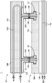
- the intermediate medium type heat exchanger 1 includes an intermediate medium evaporator E1, a liquefied gas vaporizer E2, a communication pipe 30, and a liquid reservoir 40.
- the intermediate medium heat exchanger 1 has a closed space formed by an intermediate medium evaporator E1, a liquefied gas vaporizer E2, and a communication pipe 30.
- the intermediate media LM and GM are enclosed in this space.
- the intermediate medium evaporator E1 is composed of a shell-and-tube type heat exchanger. That is, the intermediate medium evaporator E1 has a hollow chamber (first chamber) 10c whose longitudinal direction is horizontal and a first heat transfer tube 10d arranged so as to pass through the first chamber 10c. , Have.
- first chamber first chamber
- first heat transfer tube 10d arranged so as to pass through the first chamber 10c.
- Have heat exchange is performed between the heat source medium in the first heat transfer tube 10d and the liquid intermediate medium LM in the first chamber 10c, and the liquid intermediate medium is heated by the heat from the heat source medium. LM evaporates. This produces a gaseous intermediate medium GM.
- the first heat transfer tube 10d has a straight tube shape and is arranged so as to pass through a lower (bottom side) portion in the first chamber 10c.
- the first heat transfer tube 10d penetrates the first chamber 10c in the longitudinal direction thereof.
- the heat source medium flows in from the left side of FIG. 1 and flows out to the right side of FIG. 1 (that is, from one side to the other side in the longitudinal direction in the heat transfer tube 10d).
- a plurality of first heat transfer tubes 10d are provided.
- a liquid intermediate medium LM is accumulated in the first chamber 10c in the operating state of the intermediate medium type heat exchanger 1.
- the first heat transfer tube 10d is immersed in the liquid intermediate medium LM accumulated in the first chamber 10c.
- the liquefied gas vaporizer E2 is composed of a shell-and-tube type heat exchanger. That is, the liquefied gas vaporizer E2 passes through the hollow chamber (second chamber) 20c arranged above the first chamber 10c and having the longitudinal direction horizontal, and the inside of the second chamber 20c. It has a second heat transfer tube 20d, which is arranged in.
- heat exchange is performed between the gaseous intermediate medium GM in the second chamber 20c and the low temperature liquefied gas in the second heat transfer tube 20d.
- the low temperature liquefied gas is vaporized by the heat of the intermediate medium GM.
- the gaseous intermediate medium GM is cooled by the low-temperature liquefied gas, so that the liquid intermediate medium LM is generated.
- the second heat transfer tube 20d has a U-shape and is arranged so as to pass through the second chamber 20c at a distance from the bottom of the second chamber 20c.
- one end of the second heat transfer tube 20d is connected to one side wall portion in the longitudinal direction of the second chamber 20c, and extends to the vicinity of the other side wall portion in the longitudinal direction of the second chamber 20c.
- the second heat transfer tube 20d is folded back so as to bend in the vicinity of the other side wall portion in the longitudinal direction, and the other end is connected to the one side wall portion in the longitudinal direction of the second chamber 20c.
- a plurality of second heat transfer tubes 20d are provided.
- the second heat transfer tube 20d is not limited to the one having a U-shape, and may be a straight tubular one.
- “one side in a longitudinal direction” means the left side of FIG. 1, and "the other side in a longitudinal direction” means the right side of FIG.
- the gaseous intermediate medium GM and the liquid intermediate medium LM are accumulated as shown in FIGS. 1 and 2 in the operating state of the intermediate medium type heat exchanger 1.
- the second heat transfer tube 20d is arranged above the liquid intermediate medium LM accumulated in the second chamber 20c.
- the communication pipe 30 is a pipe having a double pipe structure including an inner pipe 31 and an outer pipe 32 arranged radially outside the inner pipe 31.
- the communication pipe 30 communicates with each other in the first chamber 10c and in the second chamber 20c through each of the inner pipe 31 and the outer pipe 32.
- the upper end of the outer pipe 32 is connected to the bottom surface portion forming the lower surface of the second chamber 20c, for example, by welding.
- the upper end of the outer tube 32 is open in the liquid intermediate medium LM that collects in the second chamber 20c.
- the middle portion of the outer pipe 32 is connected to the top surface portion forming the upper surface of the first chamber 10c, for example, by welding.
- the outer tube 32 penetrates the top surface portion of the first chamber 10c. That is, the lower end of the outer pipe 32 has entered the first chamber 10c.
- the lower end of the outer tube 32 is opened in the first chamber 10c at a position above the liquid level of the liquid intermediate medium LM accumulated in the first chamber 10c.
- the inner pipe 31 is arranged inside the outer pipe 32 so as to extend from the space in the first chamber 10c to the space in the second chamber 20c.
- the length of the inner pipe 31 is set to be longer than the length of the outer pipe 32.
- the upper end of the inner pipe 31 is set higher than the upper end of the outer pipe 32 and higher than the liquid level of the liquid intermediate medium LM collected in the second chamber 20c. Therefore, the upper end of the inner tube 31 is open in the gaseous intermediate medium GM in the second chamber 20c.
- the lower end of the inner pipe 31 is set lower than the lower end of the outer pipe 32 and higher than the liquid level of the liquid intermediate medium LM collected in the first chamber 10c. Therefore, the lower end of the inner tube 31 is open in the gaseous intermediate medium GM in the first chamber 10c.
- the communication pipe 30 forms a space inside the inner pipe 31 and between the inner pipe 31 and the outer pipe 32, respectively.
- the space inside the inner pipe 31 is referred to as the first flow path F1
- the space between the inner pipe 31 and the outer pipe 32 is referred to as the second flow path F2.
- the first flow path F1 includes a first upper opening F1b which is an opening formed by the upper end of the inner pipe 31, and a first lower opening F1a which is an opening formed by the lower end of the inner pipe 31.
- the first upper opening F1b is located above the liquid intermediate medium LM that collects in the second chamber 20c.
- the first lower opening F1a is located below the second lower opening F2a, which will be described later, and is a liquid state that accumulates in the height position of the second lower opening F2a and in the first chamber 10c. It is located between the liquid level of the intermediate medium LM.
- the second flow path F2 is an annular shape formed by the second upper opening F2b, which is an annular opening formed by the upper end of the outer tube 32 and the inner tube 31, and the lower end of the outer tube 32 and the inner tube 31. It has a second lower opening F2a, which is an opening of the above.
- the second upper opening F2b is open to the liquid intermediate medium LM accumulated in the second chamber 20c at a position below the first upper opening F1b.
- the second lower opening F2a opens at a position between the height position where the outer tube 32 connects to the first chamber 10c and the liquid level of the liquid intermediate medium LM accumulated in the first chamber 10c. There is.
- the liquid intermediate medium LM in the second chamber 20c flows into the second flow path F2 through the second upper opening F2b, and the liquid intermediate medium LM in the second flow path F2 is the second lower opening. It flows into the first chamber 10c through the portion F2a. That is, the second flow path F2 functions as a liquid flow path through which the liquid intermediate medium LM flows.
- the gaseous intermediate medium GM in the first chamber 10c flows into the first flow path F1 through the first lower opening F1a, and the gaseous intermediate medium GM in the first flow path F1 It flows into the second chamber 20c through the first upper opening F1b. That is, the first flow path F1 functions as a gas flow path through which the gaseous intermediate medium GM flows.
- the liquid reservoir 40 is a portion for accumulating the liquid intermediate medium LM, and is arranged at a position above the liquid level of the liquid intermediate medium LM in the first chamber 10c.
- the liquid reservoir 40 is radially outside the first flow path F1 (inner pipe 31) in the communication pipe 30 and below the second lower opening F2a of the second flow path F2 (at the lower end of the outer pipe 32). It is provided on the lower side).
- the liquid reservoir 40 is formed in a downwardly convex shape.
- the liquid reservoir 40 is radially outward from the outer surface of the pipe wall of the inner pipe 31 to a position radially outside the pipe wall of the outer pipe 32 on the lower side of the second lower opening F2a of the second flow path F2. It has a bottom surface portion extending and a vertical wall portion extending upward from the outer edge of the bottom surface portion to a position above the second lower opening F2a in the height direction.
- the upper edge portion of the vertical wall portion forms the upper edge portion 42 of the liquid reservoir portion 40. That is, the liquid reservoir 40 has the height of the upper edge portion 42 located above the second lower opening portion F2a of the liquid intermediate medium LM flowing out from the second lower opening portion F2a of the second flow path F2. While accumulating up to the position, the accumulated liquid intermediate medium LM is configured to overflow from the upper edge portion 42.
- the second lower opening F2a is immersed in the liquid intermediate medium LM stored in the liquid reservoir 40. Therefore, the second flow path F2 is filled with the liquid intermediate medium LM.
- the liquid intermediate medium LM accumulated in the first chamber 10c is heated and vaporized by the heat source medium via the first heat transfer tube 10d, and becomes a gaseous intermediate medium GM.
- the gaseous intermediate medium GM once accumulates on the upper side in the first chamber 10c, then rises through the first flow path F1 of the communication pipe 30, and flows into the second chamber 20c of the liquefied gas vaporizer E2. .. Then, in the second chamber 20c, the gaseous intermediate medium GM vaporizes the low-temperature liquefied gas by heating the low-temperature liquefied gas via the second heat transfer tube 20d.
- the gaseous intermediate medium GM is cooled by the low-temperature liquefied gas and condensed, and becomes the liquid intermediate medium LM again.
- the liquid intermediate medium LM once accumulated in the second chamber 20c flows into the liquid reservoir 40 in the first chamber 10c through the second flow path F2 of the communication pipe 30.
- the liquid reservoir 40 overflows the liquid intermediate medium LM from the upper edge 42 of the liquid reservoir 40 while maintaining a state in which a certain amount of the liquid intermediate medium LM is accumulated.
- the overflowing liquid intermediate medium LM is collected again in the first chamber 10c.
- the intermediate medium type heat exchanger 1 As described above, in the intermediate medium type heat exchanger 1 according to the first embodiment, the intermediate medium evaporator E1 has the first chamber 10c, and the liquefied gas vaporizer E2 has the second chamber 20c. ing. The inner space of the first chamber 10c and the inner space of the second chamber 20c communicate with each other through the communication pipe 30. Therefore, the intermediate medium type heat exchanger 1 does not need to be specially designed and can be configured by a general-purpose heat exchanger. Therefore, the cost can be suppressed.
- the liquid flow path and the gas flow path are configured by the communication pipe 30 having a double pipe structure. Therefore, the number of communication pipes can be reduced as compared with the case where the liquid flow path and the gas flow path are respectively formed by a plurality of communication pipes having a single pipe structure provided at different positions. Therefore, when the communication pipe 30 is welded to the first chamber 10c and the second chamber 20c, respectively, the possibility of the gaseous intermediate medium GM leaking from each welded portion of the communication pipe 30 is reduced. be able to.
- the liquid intermediate medium LM is filled in the second flow path F2 by storing the liquid intermediate medium LM in the liquid reservoir 40. Therefore, the state in which the liquid intermediate medium LM easily flows in the second flow path F2 is maintained.
- the liquid reservoir portion 40 of the second flow path F2 is filled with the liquid intermediate medium LM, the liquid intermediate medium LM in the first chamber 10c It is not necessary to extend the second flow path F2 to a position below the liquid level of.
- the state in which a certain amount of the liquid intermediate medium LM is accumulated in the liquid reservoir 40 is maintained, while the second lower opening F2a is the liquid. It is located below the upper edge 42 of the reservoir 40. Therefore, the gaseous intermediate medium GM in the first chamber 10c cannot go from the upper edge 42 of the liquid reservoir 40 to the second lower opening F2a. Therefore, the second flow path F2 is in a state of being liquid-sealed by the liquid reservoir 40.
- the liquid reservoir 40 can be easily provided in the communication pipe 30 having a multi-tube structure, and the cost can be suppressed.
- the liquid reservoir 40, the first lower opening F1a and the first upper opening F1b of the first flow path F1, and the second upper opening F2b of the second flow path F2 are in the form of FIGS. 1 and 2. Not limited.
- the liquid reservoir 40 is formed in a shape including a curved surface that bends the downward flow of the liquid intermediate medium LM passing through the liquid reservoir 40 into the upward flow. May be. More specifically, the bottom surface portion of the liquid reservoir portion 40 may be curved so as to project downward on the lower side of the second lower opening portion F2a of the second flow path F2.
- first lower opening F1a and the first upper opening F1b of the first flow path F1 may be formed in a tapered shape (reverse taper shape) so as to increase the opening diameter, respectively.
- the second upper opening F2b of the second flow path F2 may be formed in a tapered shape (reverse taper shape) so as to increase the opening diameter.
- the liquid reservoir 40 is formed in a shape including a curved surface, the liquid intermediate medium LM passing through the liquid reservoir 40 bends in a curved shape. Turn around like this. As a result, the flow resistance of the liquid intermediate medium LM passing through the liquid reservoir 40 is reduced, and the pressure loss due to the liquid reservoir 40 is suppressed.
- first lower opening F1a and the first upper opening F1b of the first flow path F1 are formed in a reverse taper shape as described above, the first flow path F1 through which the gaseous intermediate medium GM flows. Pressure loss due to
- the second upper opening F2b of the second flow path F2 is formed in a reverse taper shape as described above, the pressure loss due to the second flow path F2 through which the liquid intermediate medium LM flows can be suppressed.
- the length of the communication pipe 30 can be suppressed. It becomes. That is, in the liquid intermediate medium LM passing through the second flow path F2, the liquid level below the upper liquid level (the liquid level of the liquid intermediate medium LM accumulated in the second chamber 20c) (the liquid reservoir 40).
- the difference in the liquid level height to the liquid level of the liquid intermediate medium LM accumulated in the liquid intermediate medium) is the sum of the pressure losses in the communication pipe 30 and the liquid reservoir 40 (the pressure in the first chamber 10c and the second chamber 20c). Balanced with the pressure inside). Therefore, when the pressure loss is suppressed, the difference in the liquid level height becomes small, so that the length required for the communication pipe 30 can be suppressed.
- the communication pipe 30 may have, for example, the liquid inflow suppressing member 34 shown in FIGS. 4 and 5.
- the liquid inflow suppressing member 34 is for suppressing the inflow of the liquid intermediate medium LM into the first flow path F1, and is configured to extend downward from the liquid reservoir 40.
- the liquid inflow suppressing member 34 is formed in an annular shape surrounding the lower end of the inner pipe 31, that is, the first lower opening F1a of the first flow path F1, and is formed from the bottom surface of the liquid reservoir 40. It is formed to hang down.
- the lower end portion 35 of the liquid inflow suppressing member 34 is located below the first lower opening portion F1a of the first flow path F1.
- the liquid inflow suppressing member 34 is preferably formed continuously in the circumferential direction of the first flow path F1, but may be formed discontinuously in the circumferential direction. Further, as in the third modification shown in FIG. 5, the liquid inflow suppressing member 34 is inclined with respect to the vertical direction so as to move downward from the first lower opening F1a in the radial direction. May be good.
- the liquid intermediate medium LM is passed through the first lower opening F1a by the liquid inflow suppressing member 34.
- the inflow into one flow path F1 is suppressed. That is, when the droplets flow into the first flow path F1, they may adhere to the inner surface of the first flow path F1, but the liquid inflow suppressing member 34 causes the droplets to flow into the flow path F1. It is deterred. Therefore, in the intermediate medium type heat exchanger 1 according to the second modification and the third modification, the liquid inflow suppressing member 34 suppresses the decrease in the heat exchange efficiency of the intermediate medium type heat exchanger 1.
- the lower end portion 35 of the liquid inflow suppressing member 34 is the first lower side of the first flow path F1. It is located below the opening F1a. Therefore, the liquid intermediate medium LM flowing out of the liquid reservoir 40 rides on the flow of the gaseous intermediate medium GM that is about to enter the first lower opening F1a, and the first flow passes through the first lower opening F1a. The inflow into the road F1 is more effectively suppressed.
- the liquid inflow suppressing member 34 has the first lower opening F1a in the first flow path F1. Surround in the circumferential direction. Therefore, it is prevented that the liquid intermediate medium LM flowing out from an arbitrary position in the circumferential direction of the liquid reservoir 40 flows into the first flow path F1 through the first lower opening F1a.
- the liquid inflow suppressing member 34 is inclined. That is, the distance between the lower end portion 35 of the liquid inflow suppressing member 34 and the first lower opening portion F1a becomes large. Therefore, it is more effectively suppressed that the liquid intermediate medium LM flowing out of the liquid reservoir 40 flows into the first flow path F1 through the first lower opening F1a.
- the liquid reservoir 40 may be provided in the middle of the communication pipe 30, for example, as in the fourth modification shown in FIG. That is, the liquid reservoir 40 shown in FIG. 2 is arranged below the lower end of the outer pipe 32 in the first chamber 10c. On the other hand, in the fourth modification shown in FIG. 6, the liquid reservoir 40 is arranged between the first chamber 10c and the second chamber 20c, and the inner pipe 31 and the outer pipe 32 are arranged. It is arranged in the space formed between them.
- the outer pipe 32 of the communication pipe 30 has an outer pipe upper portion 32K connected to the second chamber 20c, an outer pipe lower portion 32M connected to the first chamber 10c, and an outer pipe. It has an outer pipe enlarged diameter portion 32L provided so as to connect the upper portion 32K and the outer pipe lower portion 32M.
- the diameter of the outer pipe enlarged diameter portion 32L is larger than the diameter of the outer pipe upper portion 32K and the outer pipe lower portion 32M. That is, the outer pipe enlarged diameter portion 32L is curved or bent in the radial direction at the top surface portion extending radially outward from the outer surface of the outer pipe upper portion 32K and the tip extending downward and extending from the outer peripheral edge of the top surface portion. It has an outer wall portion connected to the upper end of the lower portion 32M of the outer pipe.
- the outer pipe enlarged diameter portion 32L covers the liquid reservoir portion 40.
- the liquid reservoir 40 is provided in the space formed by the outer pipe enlarged diameter portion 32L and the inner pipe 31.
- the bottom surface of the liquid reservoir 40 passes through the gap between the lower end of the outer pipe upper portion 32K and the upper end of the outer pipe lower portion 32M, and passes from the outer surface of the inner pipe 31 to the outer pipe upper portion 32K and the outer pipe lower side. It extends radially outward from the portion 32M. That is, unlike the first embodiment, the bottom surface portion is arranged below the lower end of the outer pipe upper portion 32K and above the upper end of the outer pipe lower portion 32M.
- the vertical wall portion of the liquid reservoir portion 40 extends from the outer peripheral end portion of the bottom surface portion to above the lower end portion of the outer pipe upper portion 32K on the outside of the outer pipe upper portion 32K.
- the upper edge portion 42 of the vertical wall portion forms a gap with the top surface portion of the outer pipe enlarged diameter portion 32L.
- the vertical wall portion forms a radial gap with the outer wall portion of the outer pipe enlarged diameter portion 32L. Further, the vertical wall portion forms a radial gap with the outer pipe upper portion 32K.
- the second flow path F2 has an upper flow path portion F21 extending downward from the second upper opening opening F2b and a lower flow path portion F22 extending upward from the second lower opening opening F2a.
- the upper flow path portion F21 is a space formed between the outer pipe upper portion 32K and the inner pipe 31.
- the lower end portion F21s of the upper flow path portion F21 is formed by the lower end of the outer pipe upper portion 32K and the inner pipe 31.
- the lower flow path portion F22 is a portion formed by the upper edge portion 42 of the vertical wall portion of the liquid reservoir portion 40 and the top surface portion of the outer pipe enlarged diameter portion 32L, and the liquid reservoir portion 40 and the outer pipe enlarged diameter portion 32L. A portion formed by the outer wall portion of the above, and a portion formed by the inner pipe 31 and the lower portion 32M of the outer pipe.
- the upper end portion F22t of the lower flow path portion F22 is formed as a space between the upper edge portion 42 of the liquid reservoir portion 40 and the top surface portion of the outer pipe enlarged diameter portion 32L.
- the liquid inflow suppressing member 34 may be provided so as to extend from the inner pipe 31. That is, the liquid inflow suppressing member 34 is below the second lower opening F2a of the second flow path F2, and is radially outside the outer surface of the inner pipe 31 forming the first flow path F1 inside. It extends so as to incline toward and downward. That is, the liquid inflow suppressing member 34 is inclined with respect to the vertical direction so as to be separated in the radial direction from the first lower opening F1a of the first flow path F1. Even in this case, the lower end portion 35 of the liquid inflow suppressing member 34 is located below the first lower opening portion F1a.
- the liquid reservoir 40 forms a downwardly convex space, and the liquid flowing through the upper flow path portion F21 of the second flow path F2 in this space.
- the intermediate medium LM of the above is stored.
- the liquid intermediate medium LM overflowing from the upper edge portion 42 of the liquid reservoir portion 40 is guided to the top surface portion and the outer wall portion of the outer pipe enlarged diameter portion 32L, flows into the lower flow path portion F22, and flows into the first chamber. Head to 10c. That is, the liquid storage portion 40 stores the liquid intermediate medium LM flowing out from the lower end portion F21s of the upper flow path portion F21, while the collected liquid intermediate medium LM is transferred to the upper end portion F22t of the lower flow path portion F22. It is configured to flow in.
- the liquid reservoir 40 a state in which a certain amount of the liquid intermediate medium LM is accumulated is maintained between the upper end portion F22t of the lower flow path portion F22 and the lower end portion F21s of the upper flow path portion F21. Since the lower end portion F21s of the upper flow path portion F21 is located below the upper end portion F22t of the lower flow path portion F22, the gaseous intermediate medium GM vaporized in the first chamber 10c is located in the lower flow path. Even if the portion F22 is raised, the gaseous intermediate medium GM cannot go toward the lower end portion F21s of the upper flow path portion F21. Therefore, the upper flow path portion F21 of the second flow path F2 is in a state of being liquid-sealed by the liquid reservoir portion 40.
- the upper flow path portion F21 which is a part of the second flow path F2 is liquid-sealed in the liquid reservoir 40 and is a liquid intermediate medium LM. be satisfied. Therefore, the state in which the liquid intermediate medium LM easily flows in the second flow path F2 is maintained, and the second flow path F2 can function as a liquid flow path.
- the liquid intermediate medium LM flows out from the liquid reservoir 40 provided in the middle of the second flow path F2 of the communication pipe 30, and then the second. Drop from the lower opening F2a. At this time, the liquid intermediate medium LM that has become droplets flows toward the first lower opening F1a located below and radially inward from the second lower opening F2a.
- the liquid inflow suppressing member 34 prevents the liquid from flowing into the first flow path F1 from the first lower opening F1a.
- the communication pipe 30 causes the space inside the inner pipe 31 to function as the second flow path F2, which is a liquid flow path, contrary to the case of the first embodiment.
- the space between the inner pipe 31 and the outer pipe 32 may function as the first flow path F1 which is a gas flow path.
- the liquid reservoir 40 may be provided below the second lower opening F2a formed by the lower end of the inner pipe 31 of the communication pipe 30.
- the communication pipe 30 includes an inner pipe 31 and an outer pipe 32 arranged radially outside the inner pipe 31.
- the upper end of the outer pipe 32 enters the second chamber 20c, and the lower end enters the first chamber 10c.
- the upper end of the outer tube 32 is located above the liquid level of the liquid intermediate medium LM accumulated in the second chamber 20c.
- the lower end of the outer tube 32 is located above the liquid level of the liquid intermediate medium LM accumulated in the first chamber 10c.
- the upper end of the inner pipe 31 enters the second chamber 20c and the lower end enters the first chamber 10c, similarly to the outer pipe 32.
- the space inside the inner tube 31 is the second flow path F2 that functions as a liquid flow path
- the upper end of the inner tube 31 is the liquid of the liquid intermediate medium LM that collects in the second chamber 20c. It is provided above the surface.
- a groove (not shown) is formed.
- the guide groove is a gutter-shaped groove connecting notches formed in a concave shape at the upper ends of the outer pipe 32 and the inner pipe 31 so as to connect the outer pipe 32 and the inner pipe 31 to a position below the liquid surface.
- the second flow path F2 is a space inside the inner pipe 31, but since it also functions as a liquid flow path in this modification, the second flow path is at a position where the guide groove is connected to the inner pipe 31.
- the second upper opening F2b of the road F2 is formed.
- the second upper opening F2b of the second flow path F2 is located below the liquid level of the liquid intermediate medium LM in the second chamber 20c.
- the lower end of the inner pipe 31 is located below the lower end of the outer pipe 32 and above the liquid level of the liquid intermediate medium LM in the first chamber 10c.
- the second flow path which is the space inside the inner pipe 31, can function as a liquid flow path, and the inner pipe 31 and the outer pipe 32 can be combined with each other.
- the first flow path which is the space between them, can function as a gas flow path.
- the liquid reservoir 40 is provided in the first chamber 10c at a position above the liquid level of the liquid intermediate medium LM.
- the liquid reservoir 40 is arranged below the first lower opening F1a of the first flow path F1 while surrounding the second lower opening F2a of the second flow path F2. ..
- the upper edge 42 of the liquid reservoir 40 is located above the lower end of the inner pipe 31 (the second lower opening F2a of the second flow path F2) and below the lower end of the outer pipe 32. Is located in. As a result, a gap is formed between the upper edge portion 42 of the liquid reservoir portion 40 and the lower end portion of the outer pipe 32.
- the liquid intermediate medium LM can overflow from the upper edge portion 42 of the liquid reservoir 40 and flow out downward from the gap, and the gaseous intermediate medium GM generated in the first chamber 10c can be generated. It is possible to flow into the first flow path F1 from the gap through the first lower opening F1a.
- the liquid reservoir 40 may be provided in the space inside the inner pipe 31 in the middle of the communication pipe 30, for example, as in the sixth modification shown in FIG. That is, in the fifth modification shown in FIG. 7, the liquid reservoir 40 is arranged in the first chamber 10c below the lower end of the inner pipe 31. On the other hand, in the sixth modification shown in FIG. 8, the liquid reservoir 40 is arranged between the first chamber 10c and the second chamber 20c, and is formed inside the inner pipe 31. It is arranged in the space.
- the outer pipe 32 of the communication pipe 30 has an outer pipe upper portion 32K connected to the second chamber 20c and an outer pipe lower side connected to the first chamber 10c. It has a portion 32M and an outer pipe enlarged diameter portion 32L provided so as to connect the outer pipe upper portion 32K and the outer pipe lower portion 32M. Unlike the fourth modification shown in FIG. 6, the upper end of the outer tube upper portion 32K is located above the liquid level of the liquid intermediate medium LM in the second chamber 20c.
- the inner pipe 31 of the communication pipe 30 enters the second chamber 20c and forms a space between the inner pipe upper portion 32K and the inner pipe upper portion 31K, and the first chamber.
- the outer pipe diameter is expanded by being provided so as to connect the inner pipe lower side portion 31M that enters the 10c and forms a space between the outer pipe lower side portion 32M, the inner pipe upper portion 31K, and the inner pipe lower portion 31M. It has an inner pipe expansion portion 31L that forms a space between the portion 32L and the portion 32L.
- the diameter of the inner pipe enlarged portion 31L is larger than the diameter of the inner pipe upper portion 31K and the inner pipe lower portion 31M. That is, the inner pipe enlarged diameter portion 31L is curved or bent in the radial direction at the top surface portion extending radially outward from the outer surface of the inner pipe upper portion 31K and the tip extending downward and extending from the outer peripheral edge of the top surface portion. It has an outer wall portion connected to the upper end of the inner pipe lower portion 31M.
- the inner pipe enlarged diameter portion 31L covers the liquid reservoir portion 40.
- the liquid reservoir 40 is provided in the space formed by the inner pipe expansion portion 31L, and is formed in a downwardly convex shape.
- the bottom surface portion of the liquid reservoir portion 40 is arranged radially between the lower end of the inner pipe upper portion 31K and the upper end of the inner pipe lower portion 31M in the space formed inside the inner pipe expansion portion 31L.
- the vertical wall portion of the liquid reservoir portion 40 extends outside the inner pipe upper portion 31K from the outer peripheral end portion of the bottom surface portion to above the lower end portion of the inner pipe upper portion 31K.
- the upper edge portion 42 of the vertical wall portion forms a gap with the top surface portion of the inner pipe enlarged diameter portion 31L.
- the vertical wall portion forms a gap between the vertical wall portion and the outer wall portion of the inner pipe enlarged diameter portion 31L. Further, the vertical wall portion forms a radial gap with the inner pipe upper portion 31K.
- the upper flow path portion F21 of the second flow path F2 is a space formed inside the inner pipe upper portion 31K in the sixth modification.
- the lower end portion F21s of the upper flow path portion F21 is formed by the lower end portion of the inner pipe upper portion 31K.
- the lower flow path portion F22 of the second flow path F2 includes a portion formed by the upper edge portion 42 of the vertical wall portion of the liquid reservoir portion 40 and the top surface portion of the inner pipe expansion portion 31L, and the liquid reservoir portion 40. It includes a portion formed by the outer wall portion of the inner pipe enlarged diameter portion 31L and a portion formed inside the inner pipe lower side portion 31M.
- the upper end portion F22t of the lower flow path portion F22 is formed as a space between the upper edge portion 42 of the liquid reservoir portion 40 and the top surface portion of the inner pipe enlarged diameter portion 31L.
- the space inside the inner pipe 31 of the communication pipe 30 is the second flow path F2 that functions as a liquid flow path.
- the upper flow path portion F21 of the second flow path F2 is formed by the liquid reservoir 40. It will be in a liquid-sealed state.
- the intermediate medium type heat exchanger 1 includes one communication pipe 30, but the configuration is not limited to the configuration including one communication pipe 30, and the configuration includes a plurality of communication pipes 30. There may be.
- a seventh modification including a plurality of communication pipes 30 will be described with reference to FIG.
- the intermediate medium type heat exchanger 1 according to the seventh modification includes a first communication pipe 30 and a second communication pipe 30B.
- the first communication pipe 30 and the second communication pipe 30B each have the same configuration as the above-mentioned communication pipe 30. That is, the first communication pipe 30 and the second communication pipe 30B may have the configuration of the communication pipe 30 disclosed in the first embodiment (FIGS. 1 and 2), or may have a first modification.
- the configuration of the communication pipe 30 disclosed in the sixth modification (FIGS. 3 to 8) may be provided.
- the intermediate medium type heat exchanger 1 according to the seventh modification is provided with a plurality of communication pipes 30, the circulation amount of the intermediate medium circulating between the intermediate medium evaporator E1 and the liquefied gas vaporizer E2 is increased. The efficiency of the intermediate medium type heat exchanger 1 can be improved.
- the inner pipe 31 and the outer pipe 32 of the communication pipe 30 are provided with a heat insulating material. That is, as shown in FIG. 11 in which the region XI of FIG. 10 is enlarged, the inner tube 31 is located between the inner tube 31A, the outer tube 31B arranged outside the inner tube 31A, and the inner tube 31A and the outer tube 31B. It is configured as a heat insulating pipe having a triple structure in which the heat insulating material 31C arranged in the above is overlapped.
- the outer pipe 32 is provided with a heat insulating material 32C at a portion in contact with the atmosphere.
- the heat insulating materials 31C and 32C have a thermal conductivity of 1/100 or less of the thermal conductivity of the inner tube 31A, the outer tube 31B, and the outer tube 32, and are, for example, glass wool, rock wool, and polystyrene foam. And rigid urethane foam or the like is used.
- the heat insulating material 31C of the inner pipe 31 can prevent the gaseous intermediate medium GM of the first flow path F1 from being cooled and liquefied by the liquid intermediate medium LM of the second flow path F2. As a result, the occurrence of the flooding phenomenon in the first flow path F1 and the decrease in the circulation amount of the intermediate medium due to the increase in the flow path resistance are suppressed. Further, the decrease in the vaporization efficiency of the gaseous intermediate medium GM in the liquefied gas vaporizer E2 is suppressed.
- the heat insulating material 31C of the inner pipe 31 and the heat insulating material 32C provided in the outer pipe 32 warm the liquid intermediate medium LM of the second flow path F2 by the atmosphere and the gaseous intermediate medium GM of the first flow path F1. It can be suppressed from being vaporized. As a result, the occurrence of the flooding phenomenon in the second flow path F2 and the decrease in the circulation amount of the intermediate medium due to the increase in the flow path resistance are suppressed. Further, since the liquid intermediate medium LM of the second flow path F2 can be suppressed from being cooled by the atmosphere, the decrease in the evaporation efficiency of the liquid intermediate medium LM in the intermediate medium evaporator E1 is suppressed.
- the heat insulating material may be provided only on one of the inner pipe 31 and the outer pipe 32.
- the inner pipe 31 may be configured as a heat insulating pipe having a triple structure using a heat insulating material only at a portion in contact with the second flow path F2.
- the outer pipe 32 is provided with a heat insulating material 32C at a portion in contact with the atmosphere, but the present invention is not limited to this.
- the outer pipe 32 has a triple structure in which an inner pipe, an outer pipe arranged outside the inner pipe, and a heat insulating material arranged between the inner pipe and the outer pipe are overlapped, similarly to the inner pipe 31. It may be configured as a heat insulating pipe.
- the vertical wall portion and the bottom surface portion of the liquid reservoir portion 40 have a triple structure in which an inner member, an outer member, and a heat insulating material arranged between the inner member and the outer member are overlapped, similarly to the inner pipe 31. It may be configured as a heat insulating member of.
- the internal space of the first chamber 10c and the internal space of the second chamber 20c communicate with each other through the communication pipe 30 having a multi-tube structure. ..
- the communication pipe 30 in the second embodiment is a second flow path F2 in which the inner space of the inner pipe 31 functions as a liquid flow path, and the space between the inner pipe 31 and the outer pipe 32 functions as a gas flow path.
- One flow path F1 is used.
- the lower end of the inner pipe 31 is lower than the lower end of the outer pipe 32 and is arranged at a position lower than the liquid level of the liquid intermediate medium LM accumulated in the first chamber 10c. That is, the second lower opening F2a of the second flow path F2 is arranged at a position below the liquid level of the liquid intermediate medium LM in the first chamber 10c. Therefore, the second lower opening F2a is immersed in the liquid intermediate medium LM.
- the second lower opening F2a which is the lower end of the second flow path F2 functioning as a liquid flow path, is a liquid accumulated in the first chamber 10c. Immersed in the intermediate medium LM. Therefore, the operation can be performed in a state where the entire second flow path F2 is filled with the liquid intermediate medium LM. Therefore, even if the gaseous intermediate medium GM flows into the second flow path F2, the state in which the liquid intermediate medium LM easily flows in the second flow path F2 is maintained, and the second flow path F2 It can continue to function as a liquid flow path.
- the communication pipe 30 is not limited to the form shown in FIG.
- the inner tube 31 is not a straight tube in the first chamber 10c, but a horizontal direction, for example, a direction orthogonal to the extending direction of the first heat transfer tube 10d ( It may be bent in the left-right direction of FIG. 13 to form a crank shape.
- the second lower opening F2a of the second flow path F2 is located below the liquid level of the liquid intermediate medium LM in the first chamber 10c, and is a first heat transfer tube. It is arranged at a position shifted laterally from directly above 10d.
- the first The gaseous intermediate medium GM generated from the heat transfer tube 10d may flow into the second lower opening F2a.
- the second lower opening F2a is arranged at a position shifted laterally from directly above the first heat transfer tube 10d. 2 The inflow of the gaseous intermediate medium GM from the lower opening F2a into the second flow path F2 is suppressed.
- the gas inflow suppressing member 50 is provided as in the second modification shown in FIG. 14 and the third modification shown in FIG. You may.
- the gas inflow suppressing member 50 suppresses the gaseous intermediate medium GM in the first chamber 10c from flowing into the second flow path F2 through the second lower opening F2a.
- the gas inflow suppressing member 50 is a plate-shaped member arranged so as to extend horizontally between the second lower opening F2a and the first heat transfer tube 10d. That is, the gas inflow suppression member 50 is a gas inflow suppression plate having a portion located below the second lower opening F2a of the second flow path F2. The gas inflow suppressing member 50 has a sufficient area to cover the second lower opening F2a and make it invisible when viewed upward from the bottom surface of the first chamber 10c.
- the gas generated in the first heat transfer tube 10d in the first chamber 10c Even if the intermediate medium GM floats in the liquid, the intermediate medium GM is prevented from flowing into the second flow path F2 through the second lower opening F2a by the gas inflow suppressing member 50.
- the inner space of the inner pipe 31 is used as the first flow path F1 that functions as a gas flow path, and the inner pipe 31 and the outer pipe 32 are used.
- the space between them may be used as a second flow path F2 that functions as a liquid flow path.
- the outer tube 32 forming the second flow path F2 is not a straight tube, but is radially separated from the inner tube 31 in the first chamber 10c, for example, the first heat transfer tube 10d. It may be bent in a direction orthogonal to the extending direction (left-right direction in FIG. 16) to form a crank shape.
- the outer tube 32 extends in the first chamber 10c in a direction away from the inner tube 31 to a position below the liquid level of the liquid intermediate medium LM, while the first flow path formed by the inner tube 31 forms.
- the first lower opening F1a of F1 is located above the liquid surface. Therefore, the communication pipe 30 further has an intermediate wall 33.
- the intermediate wall 33 is located between the outer pipe 32 and the outer pipe 32 at a position lower than the position where the outer pipe 32 bends outward in the radial direction and above the second lower opening F2a.
- the liquid level of the liquid intermediate medium LM in the first chamber 10c, which is bent downward from this part and the part extending radially outward from the inner pipe 31 at a necessary interval as the second flow path F2. Includes a portion extending below the position.
- the space formed between the outer pipe 32 and each of the inner pipe 31 and the intermediate wall 33 is the second flow path F2.
- the second flow path F2 bends along with the bending of the outer tube 32 and the intermediate wall 33, and extends to a position shifted laterally from directly above the first heat transfer tube 10d.
- the second lower opening F2a of the second flow path F2 is located below the liquid level of the liquid intermediate medium LM in the first chamber 10c and is directly above the first heat transfer tube 10d. It is placed in a position shifted to the side.
- the second lower opening F2a is the first heat transfer tube in the first chamber 10c, as in the first modification of the second embodiment described above. It is arranged at a position shifted laterally from directly above 10d. Therefore, the inflow of the gaseous intermediate medium GM from the second lower opening F2a into the second flow path F2 is suppressed.
- FIG. 17 shows a fifth modification of the second embodiment in which the gas inflow suppressing member 50 is further provided in the fourth modification shown in FIG.
- the intermediate medium evaporator E1 further has a gas inflow suppressing member 50 arranged between the second lower opening F2a of the second flow path F2 and the first heat transfer tube 10d.
- the gaseous intermediate medium GM is more effectively suppressed from flowing into the second flow path F2 through the second lower opening F2a.
- the intermediate medium type heat exchanger 1 may include a plurality of communication pipes 30. Also in this case, the circulation amount of the intermediate medium in the entire intermediate medium type heat exchanger 1 can be increased, and the efficiency of the intermediate medium type heat exchanger 1 can be improved.
- the diameters of the inner pipe 31 and the outer pipe 32 may be set so that the hydraulic diameter of the first flow path F1 is larger than the hydraulic diameter of the second flow path F2.
- the pressure loss in the first flow path F1 functioning as a gas flow path is larger than the pressure loss in the second flow path F2 functioning as a liquid flow path. Therefore, if the hydraulic diameter of the first flow path F1 is larger than the hydraulic diameter of the second flow path F2, it is possible to suppress the pressure loss due to the first flow path F1.
- the liquid level height in the second flow path F2 is suppressed, so that the length of the communication pipe 30 can be further shortened.
- A is the cross-sectional area of the flow
- P is the circumference of the wet portion (wet edge) of the cross section.
- the hydraulic diameter of the flow path formed in the inner pipe 31 is equal to the inner diameter of the inner pipe 31.
- the hydraulic diameter DHr of the flow path formed between the inner pipe 31 and the outer pipe 32 has the cross-sectional area of the flow path Ar and the inner pipe.
- DHr 4Ar / ⁇ ⁇ (D1 + D2) ⁇ Is calculated as.
- the communication pipe 30 has been described above as a double pipe structure composed of an inner pipe 31 and an outer pipe 32, but the communication pipe 30 is not limited to the communication pipe having a double pipe structure, and is not limited to a double pipe or more. It may be a communication pipe having a structure using multiple pipes. In this case, which of the plurality of spaces separated by the plurality of pipes overlapping in the radial direction in the communication pipe 30 is used as the liquid flow path and which is used as the gas flow path is arbitrary and limited. is not it.
- the communication pipe 30 may have a shape asymmetrical in the radial direction as long as it is a communication pipe having a multi-tube structure.
- the communication pipe 30 may be such that the central axis of the inner pipe 31 and the central axis of the outer pipe 32 do not overlap and are eccentric. Further, both or one of the inner pipe 31 and the outer pipe 32 does not have to be a circular pipe.
- the liquid reservoir 40 has a shape including a curved surface that bends the downward flow of the liquid intermediate medium LM passing through the liquid reservoir 40 into the upward flow in the first modification of the first embodiment shown in FIG.
- the liquid reservoir portion 40 may be formed in the same manner, the liquid reservoir portion 40 in other modified examples may also be formed in a shape including a curved surface.
- the inner pipe 31 and the outer pipe 32 of the communication pipe 30 are provided with a heat insulating material.
- the inner pipe 31 includes the inner pipe 31A, the outer pipe 31B arranged outside the inner pipe 31A, and the inner pipe 31A. It is configured as a heat insulating pipe having a triple structure in which a heat insulating material 31C arranged between the outer pipes 31B is overlapped.
- the outer pipe 32 is provided with a heat insulating material 32C at a portion in contact with the atmosphere.
- the heat insulating material 31C of the inner pipe 31 can prevent the liquid intermediate medium LM of the second flow path F2 from being heated and vaporized by the gaseous intermediate medium GM of the first flow path F1. As a result, in the second flow path F2, the occurrence of the flooding phenomenon and the decrease in the circulation amount of the intermediate medium due to the increase in the flow path resistance are suppressed.
- the gaseous intermediate medium GM of the first flow path F1 is replaced by the liquid intermediate medium LM of the atmosphere and the second flow path F2. It can be prevented from being cooled and liquefied. As a result, the occurrence of the flooding phenomenon in the first flow path F1 and the decrease in the circulation amount of the intermediate medium due to the increase in the flow path resistance of the first flow path F1 are suppressed. Further, the decrease in the vaporization efficiency of the gaseous intermediate medium GM in the liquefied gas vaporizer E2 is suppressed.
- the heat insulating material may be provided only on one of the inner pipe 31 and the outer pipe 32.
- the inner pipe 31 may be configured as a heat insulating pipe having a triple structure using a heat insulating material only at a portion in contact with the first flow path F1.
- the outer pipe 32 is provided with a heat insulating material 32C at a portion in contact with the atmosphere, but the present invention is not limited to this.
- the outer pipe 32 has a triple structure in which an inner pipe, an outer pipe arranged outside the inner pipe, and a heat insulating material arranged between the inner pipe and the outer pipe are overlapped, similarly to the inner pipe 31. It may be configured as a heat insulating pipe.
- the intermediate medium type heat exchanger includes a hollow first chamber, a first heat transfer tube arranged so as to pass through the first chamber, and a heat transfer tube into which a heat source medium flows.
- An intermediate medium evaporator having the above, a hollow second chamber arranged above the first chamber, and a second chamber arranged so as to pass through the second chamber and into which the low temperature liquefied gas flows.
- It is a multi-tube structure including a liquefied gas vaporizer having a heat transfer tube, an inner tube, and an outer tube arranged radially outside the inner tube, and has an internal space of the first chamber and the second. It is provided with a communication pipe that communicates with the internal space of the chamber.
- An intermediate medium is enclosed in the space provided by the first chamber, the second chamber, and the communication pipe.
- the liquid intermediate medium in the first chamber is heated by the heat source medium via the first heat transfer tube and vaporized to become a gaseous intermediate medium, which is gaseous in the second chamber.
- the intermediate medium is cooled by the low-temperature liquefied gas through the second heat transfer tube and condensed to become a liquid intermediate medium. Then, when one of the space inside the inner pipe and the space between the inner pipe and the outer pipe is used as the first flow path and the other is used as the second flow path, the first flow is used.
- the path is above the first upper opening that opens above the liquid level of the liquid intermediate medium in the second chamber and above the liquid level of the liquid intermediate medium in the first chamber.
- the second flow path has a first lower opening that opens at the upper position, and functions as a gas flow path through which a gaseous intermediate medium flows.
- the second flow path has a second upper opening that opens at a position below the liquid level of the liquid intermediate medium in the second chamber, and a second lower opening that opens in the first chamber. It has a side opening and functions as a liquid flow path through which the liquid intermediate medium flows in a state where the liquid intermediate medium is filled with at least a part thereof.
- the liquid intermediate medium accumulated in the first chamber is heated by the heat source medium in the first chamber via the first heat transfer tube and vaporized, and is a gaseous intermediate medium. become.
- the gaseous intermediate medium rises through a first flow path that functions as a gas flow path within the communication pipe and flows into the second chamber of the liquefied gas vaporizer.
- the gaseous intermediate medium vaporizes the low-temperature liquefied gas by heating the low-temperature liquefied gas via the second heat transfer tube.
- the gaseous intermediate medium is cooled by the cryogenic liquefied gas and condensed, and becomes a liquid intermediate medium again.
- the liquid intermediate medium accumulated in the second chamber flows into the first chamber through the second flow path that functions as the liquid flow path in the communication pipe.
- the intermediate medium evaporator has the first chamber
- the liquefied gas vaporizer has the second chamber
- the internal space of the first chamber is provided.
- the internal space of the second chamber are communicated with each other by a communication pipe. Therefore, it does not need to be specially designed and manufactured, and can be configured by a general-purpose heat exchanger. Therefore, the cost can be suppressed.
- the liquid flow path and the gas flow path are configured by a communication pipe having a multi-tube structure. Therefore, the number of communication pipes can be reduced as compared with the case where the liquid flow path and the gas flow path are each composed of a plurality of single-tube structure communication pipes provided at different positions.
- the second flow path is at least partially filled with the liquid intermediate medium. Therefore, even if the gaseous intermediate medium flows into the second flow path, the state in which the liquid intermediate medium easily flows in the second flow path is maintained, and the second flow path functions as a liquid flow path. can do.
- the intermediate medium type heat exchanger is located above the liquid level of the liquid intermediate medium in the first chamber in the second flow path. Is further provided with a liquid reservoir for accumulating the liquid intermediate medium.
- the position is below the liquid level of the liquid intermediate medium in the first chamber. There is no need to extend the second flow path to.
- the liquid reservoir stores the liquid intermediate medium that has flowed out from the second lower opening of the second flow path, while the liquid pool has accumulated.
- the intermediate medium is configured to overflow from the upper edge portion located above the second lower opening.
- the state in which a certain amount of liquid intermediate medium is accumulated is maintained in the liquid reservoir, while the second lower opening is larger than the upper edge of the liquid reservoir. It is located below. Therefore, the gaseous intermediate medium in the first chamber cannot go from the upper edge of the liquid reservoir to the second lower opening. Therefore, the second flow path is in a state of being liquid-sealed by the liquid reservoir portion.
- a liquid reservoir can be easily provided in the communication pipe of the multi-tube structure, and the cost can be suppressed.
- the second flow path extends downward from the second upper opening and the upper end extends upward from the second lower opening.
- the portion further includes a lower flow path portion located above the lower end portion of the upper flow path portion.
- the liquid reservoir stores the liquid intermediate medium that has flowed out from the lower end of the upper flow path, while the liquid intermediate medium that has accumulated is stored in the upper end of the lower flow path. It may be configured to flow into.
- the liquid intermediate medium condensed in the second chamber flows into the liquid reservoir portion from the lower end portion of the upper flow path portion of the second flow path, and flows from the liquid reservoir portion. It flows into the upper end of the lower flow path.
- a state in which a certain amount of liquid intermediate medium is accumulated is maintained between the upper end portion of the lower flow path portion and the lower end portion of the upper flow path portion. Since the lower end of the upper flow path is located below the upper end of the lower flow path, the gaseous intermediate medium vaporized in the first chamber rises up the lower flow path. Even so, the gaseous intermediate medium cannot go toward the lower end of the upper flow path. Therefore, the upper flow path portion of the second flow path is in a state of being liquid-sealed by the liquid reservoir portion.
- the liquid reservoir is formed into a shape including a curved surface that bends the downward flow of the liquid intermediate medium passing through the liquid reservoir into an upward flow. Has been done.
- the liquid reservoir portion is formed in a shape including the curved surface, the direction of the liquid intermediate medium passing through the liquid reservoir portion is changed so as to bend in a curved shape. As a result, the flow resistance of the liquid intermediate medium passing through the liquid reservoir is reduced, and the pressure loss due to the liquid reservoir is suppressed.
- the first flow path is formed as a space inside the inner pipe of the communication pipe, and the second flow path includes the inner pipe and the outer pipe. It is formed as a space between.
- the communication pipe has the first lower opening on the flow of the gaseous intermediate medium in which the liquid intermediate medium flowing out of the liquid reservoir tries to enter the first lower opening.
- a liquid inflow suppressing member for suppressing the inflow into the first flow path through the unit may be further provided.
- the second flow path is located radially outside the first flow path. Therefore, if the liquid inflow restraining member is not provided, the liquid intermediate medium flowing out of the liquid reservoir rides on the flow of the gaseous intermediate medium trying to enter the first lower opening. Attempts to flow into the first flow path through the lower opening. Therefore, in the first flow path that functions as a gas flow path, the liquid intermediate medium may interfere with the flow of the gaseous intermediate medium. When the flow of the gaseous intermediate medium is obstructed, the circulation amount of the intermediate medium in the entire intermediate medium type heat exchanger is reduced, and the efficiency of the intermediate medium type heat exchanger is reduced.
- the liquid intermediate medium is prevented from flowing into the first flow path through the first lower opening by the liquid inflow suppressing member. Therefore, in the intermediate medium type heat exchanger according to this aspect, the efficiency of the intermediate medium type heat exchanger is suppressed from being lowered by the liquid inflow suppressing member.
- the liquid inflow suppressing member extends downward from the liquid reservoir portion and is located below the first lower opening portion of the first flow path. Has a lower end.
- the lower end portion of the liquid inflow suppressing member extending downward from the liquid reservoir portion is located below the first lower opening portion of the first flow path. Therefore, the liquid intermediate medium flowing out of the liquid reservoir rides on the flow of the gaseous intermediate medium trying to enter the first lower opening and flows into the first flow path through the first lower opening. Is more effectively deterred.
- the liquid inflow suppressing member is inclined with respect to the vertical direction so as to be radially away from the first lower opening of the first flow path. ing.
- the distance between the lower end portion of the liquid inflow suppressing member and the first lower opening portion becomes large, and the liquid intermediate medium flowing out from the liquid reservoir portion is the first lower portion.
- the inflow into the first flow path through the side opening is more effectively suppressed.
- the liquid inflow suppressing member is continuous in the circumferential direction of the first flow path so as to surround the first lower opening of the first flow path. It is formed sequentially or discontinuously.
- the liquid inflow suppressing member surrounds the first lower opening in the circumferential direction of the first flow path. Therefore, it is prevented that the liquid intermediate medium flowing out from an arbitrary position in the circumferential direction of the liquid reservoir portion flows into the first flow path through the first lower opening. Further, in this embodiment, when the liquid inflow suppressing member is formed discontinuously, the liquid inflow suppressing member suppresses the inflow of the liquid intermediate medium but does not suppress the inflow of the gaseous intermediate medium. It will be possible.
- the second lower opening of the second flow path is lower than the liquid level of the liquid intermediate medium in the first chamber. By being placed at the position, it is immersed in the liquid intermediate medium.
- the second lower opening which is the lower end of the second flow path that functions as a liquid flow path, is immersed in the liquid intermediate medium accumulated in the first chamber. .. Therefore, the operation can be performed in a state where the entire second flow path is filled with the liquid intermediate medium. Therefore, even if the gaseous intermediate medium flows into the second flow path, the state in which the liquid intermediate medium easily flows in the second flow path is maintained, and the second flow path functions as a liquid flow path. Can continue to do.
- the second lower opening of the second flow path is arranged laterally from directly above the first heat transfer tube in the first chamber. It is placed in a misaligned position.
- the second lower opening of the second flow path immersed in the liquid intermediate medium in the first chamber is arranged directly above the first heat transfer tube, the second lower opening is passed through the second lower opening.
- a gaseous intermediate medium generated from the first heat transfer tube will flow into the flow path.
- the second lower opening is arranged in the first chamber at a position shifted laterally from directly above the first heat transfer tube, the second is The inflow of the gaseous intermediate medium from the lower opening into the second flow path is suppressed.
- the gaseous intermediate medium in the first chamber is passed through the second lower opening into the second flow path. It also has a gas inflow suppression member that suppresses the inflow to the gas.
- the second flow is from the second lower opening. The inflow into the road is suppressed.
- the hydraulic diameter of the first flow path is larger than the hydraulic diameter of the second flow path.
- the pressure loss due to the first flow path through which the gaseous intermediate medium flows can be suppressed.
- the first upper opening and the first lower opening of the first flow path are formed in a reverse taper shape so as to increase the opening diameter. ing.
- the pressure loss due to the first flow path through which the gaseous intermediate medium flows can be suppressed.
- the second upper opening of the second flow path is formed in a reverse taper shape so as to increase the opening diameter.
- the pressure loss due to the second flow path through which the liquid intermediate medium flows can be suppressed.
- the intermediate medium type heat exchanger further includes a second communication pipe.
- the second communication pipe has a multi-tube structure including an inner pipe and an outer pipe arranged radially outside the inner pipe, and has an internal space of the first chamber and an internal space of the second chamber. May communicate with each other.
- one of the space inside the inner pipe and the space between the inner pipe and the outer pipe is the first flow path, and the other is the second flow path.
- the intermediate medium type heat exchanger includes a plurality of communication pipes, the circulation amount of the intermediate medium circulating between the intermediate medium evaporator and the liquefied gas vaporizer can be increased, and the intermediate medium can be increased. The efficiency of the type heat exchanger can be improved.
- a heat insulating material is provided on at least one of the inner pipe and the outer pipe.
- the intermediate medium type heat exchanger when the inner pipe is provided with a heat insulating material, the influence of heat exchange between the inner pipe and the outer pipe is suppressed, and the heat insulating material is provided on the outer pipe. If so, the effect of heat exchange between the intermediate medium flowing through the outer tube and the atmosphere can be suppressed.
- the cost can be suppressed.
Landscapes
- Engineering & Computer Science (AREA)
- Mechanical Engineering (AREA)
- General Engineering & Computer Science (AREA)
- Heat-Exchange Devices With Radiators And Conduit Assemblies (AREA)
- Filling Or Discharging Of Gas Storage Vessels (AREA)
Abstract
Description
中間媒体式熱交換器は、熱源媒体と低温液化ガスとの間で中間媒体を介して熱交換させる熱交換器である。中間媒体式熱交換器は、中間媒体を循環させながら熱源媒体の熱を、中間媒体を介して液化天然ガス(LNG)に伝熱する。これにより、LNGが気化されて天然ガス(NG)が生成される。なお、中間媒体式熱交換器は、低温液化ガスとしてLNGを気化させる構成に限られず、例えばエチレン、液化酸素、液化窒素等を気化させるものであってもよい。熱源媒体は、海水、工業用水等である。
次に、第2実施形態に係る中間媒体式熱交換器1を、図12に基づいて説明する。なお、第2実施形態において、上記の第1実施形態と同一の構成要素については同一の符号を用いて説明を省略することとし、主に異なる構成要素について説明を行う。
DH=4A/P
ここで、Aは、流れの断面積であり、Pは、断面のうち濡れている部分(濡れ縁)の周長である。
DHr=4Ar/{π×(D1+D2)}
として、計算される。
Claims (17)
- 中空状の第1のチャンバと、前記第1のチャンバ内を通過するように配置され熱源媒体が流入する第1の伝熱管と、を有する中間媒体蒸発器と、
前記第1のチャンバよりも上方に配置される中空状の第2のチャンバと、前記第2のチャンバ内を通過するように配置され低温液化ガスが流入する第2の伝熱管と、を有する液化ガス気化器と、
内管と前記内管の径方向外側に配置される外管とを含む多重管構造であり、前記第1のチャンバの内部空間と前記第2のチャンバの内部空間とを相互に連通する連通管と、
を備え、
前記第1のチャンバ、前記第2のチャンバ及び前記連通管による空間内には中間媒体が封入されており、
前記第1のチャンバ内の液状の中間媒体は、前記第1の伝熱管を介して前記熱源媒体に加熱されて気化し、ガス状の中間媒体になり、
前記第2のチャンバ内のガス状の中間媒体は、前記第2の伝熱管を介して前記低温液化ガスに冷やされて凝縮し、液状の中間媒体になり、
前記内管の内側の空間、及び、前記内管と前記外管との間の空間のうちの一方を第1流路とし、他方を第2流路としたときに、
前記第1流路は、
前記第2のチャンバ内における前記液状の中間媒体の液面よりも上側の位置で開口する第1上側開口部と、
前記第1のチャンバ内における前記液状の中間媒体の液面よりも上側の位置で開口する第1下側開口部と、
を有し、ガス状の中間媒体が流れるガス流路として機能し、
前記第2流路は、
前記第2のチャンバ内における前記液状の中間媒体の液面よりも下側の位置で開口する第2上側開口部と、
前記第1のチャンバ内で開口する第2下側開口部と、
を有し、少なくとも一部において前記液状の中間媒体で満たされた状態で、前記液状の中間媒体が流れる液流路として機能する、
中間媒体式熱交換器。 - 前記第2流路において、前記第1のチャンバ内における前記液状の中間媒体の液面よりも上側の位置に設けられ、前記液状の中間媒体を溜める液溜め部を更に備える、
請求項1に記載の中間媒体式熱交換器。 - 前記液溜め部は、
前記第2流路の前記第2下側開口部から流出した前記液状の中間媒体を溜める一方で、溜まった前記液状の中間媒体を、前記第2下側開口部よりも上側に位置する上縁部から溢れさせるように構成されている、
請求項2に記載の中間媒体式熱交換器。 - 前記第2流路は、前記第2上側開口部から下方に延びる上側流路部と、前記第2下側開口部から上方に延び且つ上端部が前記上側流路部の下端部よりも上方に位置する下側流路部と、を更に有し、
前記液溜め部は、前記上側流路部の前記下端部から流出した前記液状の中間媒体を溜める一方で、溜まった前記液状の中間媒体を、前記下側流路部の前記上端部に流入させるように構成されている、
請求項2に記載の中間媒体式熱交換器。 - 前記液溜め部は、前記液溜め部を通過する前記液状の中間媒体の下向きの流れを上向きの流れに曲げる曲面を含んだ形状に形成されている、
請求項3又は請求項4に記載の中間媒体式熱交換器。 - 前記第1流路は前記連通管の前記内管の内側の空間として形成され、前記第2流路は前記内管と前記外管との間の空間として形成され、
前記連通管は、前記液溜め部から流出した前記液状の中間媒体が、前記第1下側開口部に入ろうとする前記ガス状の中間媒体の流れに乗って前記第1下側開口部を通じて前記第1流路内に流入することを抑止する液流入抑止部材を更に有する、
請求項2に記載の中間媒体式熱交換器。 - 前記液流入抑止部材は、前記液溜め部から下方に延び、前記第1流路の前記第1下側開口部よりも下方に位置する下端部を有する、
請求項6に記載の中間媒体式熱交換器。 - 前記液流入抑止部材は、前記第1流路の前記第1下側開口部から径方向に離れるように、鉛直方向に対して傾斜している、
請求項6に記載の中間媒体式熱交換器。 - 前記液流入抑止部材は、前記第1流路の前記第1下側開口部を取り囲むように、前記第1流路の周方向に連続的に又は不連続的に形成されている、
請求項6に記載の中間媒体式熱交換器。 - 前記第2流路の前記第2下側開口部は、前記第1のチャンバ内における前記液状の中間媒体の液面よりも下側の位置に配置されることにより、前記液状の中間媒体に浸かっている、
請求項1に記載の中間媒体式熱交換器。 - 前記第2流路の前記第2下側開口部は、前記第1のチャンバ内において、前記第1の伝熱管の直上から側方にずれた位置に配置されている、
請求項10に記載の中間媒体式熱交換器。 - 前記中間媒体蒸発器は、前記第1のチャンバ内の前記ガス状の中間媒体が前記第2下側開口部を通じて前記第2流路内に流入することを抑止するガス流入抑止部材を更に有する、
請求項10に記載の中間媒体式熱交換器。 - 前記第1流路の水力直径は、前記第2流路の水力直径よりも大きい、
請求項1に記載の中間媒体式熱交換器。 - 前記第1流路の前記第1上側開口部及び前記第1下側開口部は、開口径を大きくするように逆テーパー状に形成されている、
請求項1に記載の中間媒体式熱交換器。 - 前記第2流路の前記第2上側開口部は、開口径を大きくするように逆テーパー状に形成されている、
請求項1に記載の中間媒体式熱交換器。 - 内管と前記内管の径方向外側に配置される外管とを含む多重管構造であり、前記第1のチャンバの内部空間と前記第2のチャンバの内部空間とを相互に連通し、前記内管の内側の空間、及び、前記内管と前記外管との間の空間のうちの一方を第1流路とし、他方を第2流路とする第2の連通管を更に備える、
請求項1に記載の中間媒体式熱交換器。 - 前記内管と前記外管の少なくとも一方には、断熱材が設けられている、
請求項1に記載の中間媒体式熱交換器。
Priority Applications (2)
| Application Number | Priority Date | Filing Date | Title |
|---|---|---|---|
| KR1020227043865A KR102767481B1 (ko) | 2020-06-19 | 2021-06-09 | 중간 매체식 열교환기 |
| CN202180043770.2A CN115735078B (zh) | 2020-06-19 | 2021-06-09 | 中间介质式换热器 |
Applications Claiming Priority (4)
| Application Number | Priority Date | Filing Date | Title |
|---|---|---|---|
| JP2020-106073 | 2020-06-19 | ||
| JP2020106073 | 2020-06-19 | ||
| JP2021-063427 | 2021-04-02 | ||
| JP2021063427A JP7411601B2 (ja) | 2020-06-19 | 2021-04-02 | 中間媒体式熱交換器 |
Publications (1)
| Publication Number | Publication Date |
|---|---|
| WO2021256342A1 true WO2021256342A1 (ja) | 2021-12-23 |
Family
ID=79244286
Family Applications (1)
| Application Number | Title | Priority Date | Filing Date |
|---|---|---|---|
| PCT/JP2021/021907 Ceased WO2021256342A1 (ja) | 2020-06-19 | 2021-06-09 | 中間媒体式熱交換器 |
Country Status (4)
| Country | Link |
|---|---|
| JP (1) | JP7411601B2 (ja) |
| KR (1) | KR102767481B1 (ja) |
| CN (1) | CN115735078B (ja) |
| WO (1) | WO2021256342A1 (ja) |
Citations (4)
| Publication number | Priority date | Publication date | Assignee | Title |
|---|---|---|---|---|
| JP2000227200A (ja) * | 1999-02-04 | 2000-08-15 | Kobe Steel Ltd | 中間媒体式気化器及び当該気化器を用いた天然ガスの供給方法 |
| JP2004190951A (ja) * | 2002-12-11 | 2004-07-08 | Hiroshima Gas Kk | Lng冷熱の回収方法及びその装置 |
| JP2020008130A (ja) * | 2018-07-11 | 2020-01-16 | 株式会社神戸製鋼所 | 気化器 |
| JP2020051674A (ja) * | 2018-09-26 | 2020-04-02 | 関西電力株式会社 | 熱交換設備、発電設備及び熱交換方法 |
Family Cites Families (5)
| Publication number | Priority date | Publication date | Assignee | Title |
|---|---|---|---|---|
| CH573571A5 (ja) * | 1974-01-11 | 1976-03-15 | Sulzer Ag | |
| JPS54136413A (en) * | 1978-03-28 | 1979-10-23 | Osaka Gas Co Ltd | Liquefied natural gas gasifier |
| CN102109089A (zh) * | 2009-12-25 | 2011-06-29 | 上海电机学院 | 冷能自然循环利用的方法及装置 |
| JP6651424B2 (ja) * | 2015-12-18 | 2020-02-19 | 株式会社神戸製鋼所 | 中間媒体式気化器 |
| JP6839975B2 (ja) | 2015-12-28 | 2021-03-10 | 株式会社神戸製鋼所 | 中間媒体式気化器 |
-
2021
- 2021-04-02 JP JP2021063427A patent/JP7411601B2/ja active Active
- 2021-06-09 WO PCT/JP2021/021907 patent/WO2021256342A1/ja not_active Ceased
- 2021-06-09 KR KR1020227043865A patent/KR102767481B1/ko active Active
- 2021-06-09 CN CN202180043770.2A patent/CN115735078B/zh active Active
Patent Citations (4)
| Publication number | Priority date | Publication date | Assignee | Title |
|---|---|---|---|---|
| JP2000227200A (ja) * | 1999-02-04 | 2000-08-15 | Kobe Steel Ltd | 中間媒体式気化器及び当該気化器を用いた天然ガスの供給方法 |
| JP2004190951A (ja) * | 2002-12-11 | 2004-07-08 | Hiroshima Gas Kk | Lng冷熱の回収方法及びその装置 |
| JP2020008130A (ja) * | 2018-07-11 | 2020-01-16 | 株式会社神戸製鋼所 | 気化器 |
| JP2020051674A (ja) * | 2018-09-26 | 2020-04-02 | 関西電力株式会社 | 熱交換設備、発電設備及び熱交換方法 |
Also Published As
| Publication number | Publication date |
|---|---|
| KR20230011364A (ko) | 2023-01-20 |
| JP7411601B2 (ja) | 2024-01-11 |
| JP2022001790A (ja) | 2022-01-06 |
| CN115735078A (zh) | 2023-03-03 |
| CN115735078B (zh) | 2025-08-05 |
| KR102767481B1 (ko) | 2025-02-14 |
Similar Documents
| Publication | Publication Date | Title |
|---|---|---|
| AU2002217510B8 (en) | Layered heat exchangers | |
| US10914525B2 (en) | Side mounted refrigerant distributor in a flooded evaporator and side mounted inlet pipe to the distributor | |
| CN107131783A (zh) | 一种多孔稳流装置环路热管 | |
| KR102687452B1 (ko) | 열교환기 | |
| US12123653B2 (en) | Heat exchanger | |
| KR20180098341A (ko) | 중간 매체식 기화기 | |
| WO2021145363A1 (ja) | シェルアンドプレート式熱交換器 | |
| JP3576486B2 (ja) | 蒸発器および冷凍機 | |
| JP2007212091A (ja) | シェルアンドチューブ型凝縮器 | |
| JP2016130612A (ja) | 冷媒蒸発器 | |
| US11885569B2 (en) | Heat exchanger | |
| JP7411601B2 (ja) | 中間媒体式熱交換器 | |
| JP2024537992A (ja) | マイクロチャネル熱交換器 | |
| JP4701147B2 (ja) | 2段吸収冷凍機 | |
| JP2005156141A (ja) | 空温式液化ガス気化器 | |
| WO2021235337A1 (ja) | 中間媒体式熱交換器 | |
| JP7366255B2 (ja) | 熱交換器、空気調和装置の室外機及び空気調和装置 | |
| JP2021183868A (ja) | 中間媒体式熱交換器 | |
| KR20130057548A (ko) | 응축기 | |
| JP2015030301A (ja) | タンクローリ | |
| JP2021179283A (ja) | 分配器及び熱交換器ユニット | |
| US20240361078A1 (en) | Connection-type block, header connecting body, and condenser including same | |
| KR20020078806A (ko) | 열교환기 | |
| KR20250158221A (ko) | 열교환기 | |
| JP2005069304A (ja) | 空温式液化ガス気化器 |
Legal Events
| Date | Code | Title | Description |
|---|---|---|---|
| 121 | Ep: the epo has been informed by wipo that ep was designated in this application |
Ref document number: 21825531 Country of ref document: EP Kind code of ref document: A1 |
|
| ENP | Entry into the national phase |
Ref document number: 20227043865 Country of ref document: KR Kind code of ref document: A |
|
| NENP | Non-entry into the national phase |
Ref country code: DE |
|
| 122 | Ep: pct application non-entry in european phase |
Ref document number: 21825531 Country of ref document: EP Kind code of ref document: A1 |
|
| WWG | Wipo information: grant in national office |
Ref document number: 202180043770.2 Country of ref document: CN |