WO2021255964A1 - 撮影装置 - Google Patents
撮影装置 Download PDFInfo
- Publication number
- WO2021255964A1 WO2021255964A1 PCT/JP2020/047285 JP2020047285W WO2021255964A1 WO 2021255964 A1 WO2021255964 A1 WO 2021255964A1 JP 2020047285 W JP2020047285 W JP 2020047285W WO 2021255964 A1 WO2021255964 A1 WO 2021255964A1
- Authority
- WO
- WIPO (PCT)
- Prior art keywords
- detector
- light source
- sub
- reflector
- person
- Prior art date
- Legal status (The legal status is an assumption and is not a legal conclusion. Google has not performed a legal analysis and makes no representation as to the accuracy of the status listed.)
- Ceased
Links
Images








Classifications
-
- G—PHYSICS
- G01—MEASURING; TESTING
- G01S—RADIO DIRECTION-FINDING; RADIO NAVIGATION; DETERMINING DISTANCE OR VELOCITY BY USE OF RADIO WAVES; LOCATING OR PRESENCE-DETECTING BY USE OF THE REFLECTION OR RERADIATION OF RADIO WAVES; ANALOGOUS ARRANGEMENTS USING OTHER WAVES
- G01S13/00—Systems using the reflection or reradiation of radio waves, e.g. radar systems; Analogous systems using reflection or reradiation of waves whose nature or wavelength is irrelevant or unspecified
- G01S13/88—Radar or analogous systems specially adapted for specific applications
- G01S13/887—Radar or analogous systems specially adapted for specific applications for detection of concealed objects, e.g. contraband or weapons
-
- G—PHYSICS
- G01—MEASURING; TESTING
- G01S—RADIO DIRECTION-FINDING; RADIO NAVIGATION; DETERMINING DISTANCE OR VELOCITY BY USE OF RADIO WAVES; LOCATING OR PRESENCE-DETECTING BY USE OF THE REFLECTION OR RERADIATION OF RADIO WAVES; ANALOGOUS ARRANGEMENTS USING OTHER WAVES
- G01S13/00—Systems using the reflection or reradiation of radio waves, e.g. radar systems; Analogous systems using reflection or reradiation of waves whose nature or wavelength is irrelevant or unspecified
- G01S13/003—Bistatic radar systems; Multistatic radar systems
-
- G—PHYSICS
- G01—MEASURING; TESTING
- G01S—RADIO DIRECTION-FINDING; RADIO NAVIGATION; DETERMINING DISTANCE OR VELOCITY BY USE OF RADIO WAVES; LOCATING OR PRESENCE-DETECTING BY USE OF THE REFLECTION OR RERADIATION OF RADIO WAVES; ANALOGOUS ARRANGEMENTS USING OTHER WAVES
- G01S13/00—Systems using the reflection or reradiation of radio waves, e.g. radar systems; Analogous systems using reflection or reradiation of waves whose nature or wavelength is irrelevant or unspecified
- G01S13/74—Systems using reradiation of radio waves, e.g. secondary radar systems; Analogous systems
- G01S13/75—Systems using reradiation of radio waves, e.g. secondary radar systems; Analogous systems using transponders powered from received waves, e.g. using passive transponders, or using passive reflectors
-
- G—PHYSICS
- G01—MEASURING; TESTING
- G01S—RADIO DIRECTION-FINDING; RADIO NAVIGATION; DETERMINING DISTANCE OR VELOCITY BY USE OF RADIO WAVES; LOCATING OR PRESENCE-DETECTING BY USE OF THE REFLECTION OR RERADIATION OF RADIO WAVES; ANALOGOUS ARRANGEMENTS USING OTHER WAVES
- G01S13/00—Systems using the reflection or reradiation of radio waves, e.g. radar systems; Analogous systems using reflection or reradiation of waves whose nature or wavelength is irrelevant or unspecified
- G01S13/88—Radar or analogous systems specially adapted for specific applications
- G01S13/89—Radar or analogous systems specially adapted for specific applications for mapping or imaging
-
- G—PHYSICS
- G01—MEASURING; TESTING
- G01N—INVESTIGATING OR ANALYSING MATERIALS BY DETERMINING THEIR CHEMICAL OR PHYSICAL PROPERTIES
- G01N21/00—Investigating or analysing materials by the use of optical means, i.e. using sub-millimetre waves, infrared, visible or ultraviolet light
- G01N21/17—Systems in which incident light is modified in accordance with the properties of the material investigated
- G01N2021/1765—Method using an image detector and processing of image signal
-
- G—PHYSICS
- G01—MEASURING; TESTING
- G01N—INVESTIGATING OR ANALYSING MATERIALS BY DETERMINING THEIR CHEMICAL OR PHYSICAL PROPERTIES
- G01N21/00—Investigating or analysing materials by the use of optical means, i.e. using sub-millimetre waves, infrared, visible or ultraviolet light
- G01N21/17—Systems in which incident light is modified in accordance with the properties of the material investigated
- G01N21/25—Colour; Spectral properties, i.e. comparison of effect of material on the light at two or more different wavelengths or wavelength bands
- G01N21/31—Investigating relative effect of material at wavelengths characteristic of specific elements or molecules, e.g. atomic absorption spectrometry
- G01N21/35—Investigating relative effect of material at wavelengths characteristic of specific elements or molecules, e.g. atomic absorption spectrometry using infrared light
- G01N21/3581—Investigating relative effect of material at wavelengths characteristic of specific elements or molecules, e.g. atomic absorption spectrometry using infrared light using far infrared light; using Terahertz radiation
-
- G—PHYSICS
- G01—MEASURING; TESTING
- G01N—INVESTIGATING OR ANALYSING MATERIALS BY DETERMINING THEIR CHEMICAL OR PHYSICAL PROPERTIES
- G01N21/00—Investigating or analysing materials by the use of optical means, i.e. using sub-millimetre waves, infrared, visible or ultraviolet light
- G01N21/17—Systems in which incident light is modified in accordance with the properties of the material investigated
- G01N21/47—Scattering, i.e. diffuse reflection
- G01N21/4738—Diffuse reflection, e.g. also for testing fluids, fibrous materials
-
- G—PHYSICS
- G01—MEASURING; TESTING
- G01S—RADIO DIRECTION-FINDING; RADIO NAVIGATION; DETERMINING DISTANCE OR VELOCITY BY USE OF RADIO WAVES; LOCATING OR PRESENCE-DETECTING BY USE OF THE REFLECTION OR RERADIATION OF RADIO WAVES; ANALOGOUS ARRANGEMENTS USING OTHER WAVES
- G01S13/00—Systems using the reflection or reradiation of radio waves, e.g. radar systems; Analogous systems using reflection or reradiation of waves whose nature or wavelength is irrelevant or unspecified
- G01S13/02—Systems using reflection of radio waves, e.g. primary radar systems; Analogous systems
- G01S13/06—Systems determining position data of a target
- G01S13/46—Indirect determination of position data
- G01S2013/462—Indirect determination of position data using multipath signals
Definitions
- This disclosure relates to a photographing device.
- Patent Document 1 discloses an image acquisition device that acquires an image of a subject using a terahertz wave.
- a shooting device that shoots an image of an object to be photographed using a sub-terahertz wave, it is required to effectively irradiate the object to be photographed with the sub-terahertz wave in order to improve the image quality and the like.
- the photographing apparatus covers the photographing space on the passage through which the object to be photographed passes from at least one of both sides of the passage, and the reflecting plate that diffusely reflects the subterrahertz wave and the reflecting plate.
- the first light source that emits the sub-terahertz wave and the sub-terahertz wave that was emitted from the first light source and then diffusely reflected by the reflector were received and received by the object to be photographed.
- a first detector that generates an image based on a reflected wave is provided, and the first light source and the first detector are located on the first direction side of the center of the photographing space in the extending direction of the passage. To position.
- the photographing apparatus According to the photographing apparatus according to one aspect of the present disclosure, it is possible to effectively irradiate the imaged object with a sub-terahertz wave.
- FIG. 6B is a diagram for explaining an operation example of the photographing apparatus according to the embodiment.
- FIG. 6C is a diagram for explaining an operation example of the photographing apparatus according to the embodiment.
- FIG. 6D is a diagram for explaining an operation example of the photographing apparatus according to the embodiment.
- FIG. 7 is a schematic view of the photographing apparatus according to the first modification of the embodiment when viewed from above.
- FIG. 8A is a diagram for explaining an operation example of the photographing apparatus according to the first modification of the embodiment.
- FIG. 8B is a diagram for explaining an operation example of the photographing apparatus according to the first modification of the embodiment.
- FIG. 8C is a diagram for explaining an operation example of the photographing apparatus according to the first modification of the embodiment.
- FIG. 8A is a diagram for explaining an operation example of the photographing apparatus according to the first modification of the embodiment.
- FIG. 8B is a diagram for explaining an operation example of the photographing apparatus according to the first modification of the embodiment.
- FIG. 8C is
- FIG. 8D is a diagram for explaining an operation example of the photographing apparatus according to the first modification of the embodiment.
- FIG. 9 is a schematic view of the photographing apparatus according to the second modification of the embodiment when viewed from above.
- FIG. 10A is a diagram for explaining an operation example of the photographing apparatus according to the second modification of the embodiment.
- FIG. 10B is a diagram for explaining an operation example of the photographing apparatus according to the second modification of the embodiment.
- FIG. 11 is a schematic view of the photographing apparatus according to the third modification of the embodiment when viewed from above.
- FIG. 12A is a diagram for explaining an operation example of the photographing apparatus according to the modified example 3 of the embodiment.
- FIG. 12B is a diagram for explaining an operation example of the photographing apparatus according to the modified example 3 of the embodiment.
- FIG. 12A is a diagram for explaining an operation example of the photographing apparatus according to the modified example 3 of the embodiment.
- FIG. 12C is a diagram for explaining an operation example of the photographing apparatus according to the modified example 3 of the embodiment.
- FIG. 12D is a diagram for explaining an operation example of the photographing apparatus according to the modified example 3 of the embodiment.
- FIG. 13 is a schematic view of the reflector according to the modified example when viewed from the front.
- the photographing apparatus covers the photographing space on the passage through which the object to be photographed passes from at least one of both sides of the passage, and the reflecting plate that diffusely reflects the subterrahertz wave and the reflecting plate.
- the first light source that emits the sub-terahertz wave and the sub-terahertz wave that was emitted from the first light source and then diffusely reflected by the reflector were received and received by the object to be photographed.
- a first detector that generates an image based on a reflected wave is provided, and the first light source and the first detector are located on the first direction side of the center of the photographing space in the extending direction of the passage. To position.
- the "sub-terahertz wave” means an electromagnetic wave having a frequency of 0.05 THz or more and 2 THz or less.
- the sub-terahertz wave in the present specification may be an electromagnetic wave having a frequency of 0.08 THz or more and 1 THz or less.
- "diffuse reflection” means that the sub-terahertz wave incident on the reflector at one incident angle from a macroscopic point of view has a plurality of subterahertz waves due to the structure of the uneven surface having a plurality of micro unevenness. It means that it is reflected at the reflection angle.
- the sub-terahertz wave emitted from the first light source is diffusely reflected by the reflecting plate and becomes the object to be photographed.
- the inner surface of the reflector functions as a surface light source, and the sub-terahertz wave is irradiated to a relatively wide range from various angles with respect to the object to be photographed. Visible light tends to be diffusely reflected on the surface of the object to be photographed, but since the wavelength of subterahertz waves is longer than that of visible light, the size of the surface unevenness of the object to be photographed is smaller than the wavelength of the subterahertz wave.
- the photographing apparatus can effectively irradiate the object to be photographed with a sub-terahertz wave. Further, by effectively irradiating the object to be photographed with the sub-terahertz wave, the amount of the reflected wave incident on the first detector is increased. Therefore, the image quality of the image generated by the first detector is improved.
- the reflector may sandwich the photographing space from both sides of the passage.
- the photographing device comprises a second light source that emits a subterrahertz wave to the reflector, and a subterrahertz wave that is emitted from the second light source and then diffusely reflected by the reflector.
- a second detector that receives the reflected wave from the object to be imaged and generates an image based on the received reflected wave is further provided, and the second light source and the second detector extend in the direction of the passage. In, it may be located on the second direction side opposite to the first direction from the center of the photographing space.
- the first detector generates an image on the first direction side of the object to be photographed
- the second detector generates an image on the second direction side of the object to be photographed. Therefore, it is possible to generate images on both sides in the direction in which the passage of the object to be photographed extends.
- the photographing apparatus further includes a light source control unit that controls the emission of sub-terahertz waves of each of the first light source and the second light source, and the light source control unit becomes the first light source in the first period.
- the sub-terahertz wave is not emitted to the second light source by injecting the sub-terahertz wave, and the sub-terahertz wave is emitted to the second light source in the second period different from the first period, and the sub-terahertz wave is emitted to the first light source.
- the first detector Without emitting a wave, the first detector generates an image based on the reflected wave by the photographing object received in the first period, and the second detector receives the wave in the second period. An image may be generated based on the reflected wave generated by the imaged object.
- the first light source and the second light source do not emit subterahertz waves at the same time when the first detector and the second detector generate an image. Therefore, when the image of the first detector is generated, the sub-terahertz wave derived from the second light source is not incident at the same time as the reflected wave by the imaged object, and when the image of the second detector is generated, the reflected wave by the imaged object is simultaneously generated. The sub-terahertz wave derived from the first light source is not incident. Therefore, the photographing device can generate an image in which the image due to the reflected wave by the photographing object is clear.
- one of the first detector and the second detector is based on the reflected wave received by the imaged object in the other of the first detector and the second detector.
- the exposure in the generation of the image based on the reflected wave by the received object may be started.
- the image generation by the first detector and the image generation by the second detector are performed without a time interval. Therefore, since the object to be photographed can be photographed from both the front and rear sides without opening a time interval, the area of the object to be photographed that is not photographed can be reduced.
- the first detector receives the reflected wave by the imaging object at a plurality of timings while the imaging object passes through the imaging space, and is based on each of the received reflected waves. Multiple images may be generated.
- the photographing device generates an image of the image to be photographed even before the object to be photographed enters the photographing space, so that the length of the reflector in the extending direction can be shortened.
- the photographing apparatus receives the reflected wave of the subterrahertz wave diffusely reflected by the reflecting plate after being emitted from the first light source, and becomes the received reflected wave.
- a third detector that generates an image based on the image is further provided, and the third detector is located on the first direction side of the center of the photographing space in the extending direction of the passage, and the first detector is provided. And the third detector may be different in the incident direction of the reflected wave by the image pickup object.
- the first detector and the third detector generate an image based on the reflected wave from the surface of the object to be photographed facing in a different direction.
- the first light source and the first detector are located on the same direction side of the reflector. Further, the first light source emits a sub-terahertz wave to the reflector from a position closer to the reflector than the first detector. Further, the sub-terahertz wave diffusely reflected by the reflector after being emitted from the first light source is applied to the object to be photographed without traveling to the first detector side. Therefore, the sub-terahertz wave emitted from the first light source can be efficiently used.
- the first light source is arranged along the reflector when viewed from the extending direction of the passage, and a plurality of point light sources, each of which radiates a sub-terahertz wave, and along the reflector. It may include at least one of the linear light sources that extends and emits subterahertz waves.
- the first light source can emit a wide range of sub-terahertz waves along the reflector when viewed from the direction in which the passage extends.
- each figure is not necessarily exactly illustrated.
- substantially the same configurations are designated by the same reference numerals, and duplicate explanations are omitted or simplified.
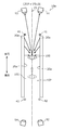
- FIG. 1 is a schematic view showing the appearance of the photographing apparatus 10 according to the present embodiment.
- components other than the reflector 20 are omitted.
- the photographing apparatus 10 irradiates the person 100 with a sub-terahertz wave, for example, when the person 100 passes through the photographing space 102 on the passage 101 sandwiched between the reflectors 20.
- This is a photographing device that captures an image based on the reflected wave of the irradiated sub-terahertz wave by the person 100.
- the photographing space 102 is a space on the passage 101 that is covered with the reflector 20.
- the photographing device 10 photographs a dangerous object such as a knife hidden under clothes or the like by the person 100, for example. Dangerous objects such as cutlery that the person 100 and the person 100 hide under clothes or the like are examples of objects to be photographed.
- the reflector 20 covers the space on the passage 101 through which the person 100 passes, specifically, the photographing space 102 from at least one of both sides of the passage 101.
- Covering from at least one of both sides of the passage 101 specifically means covering from both sides of the passage 101, that is, from at least one of two directions perpendicular to the direction in which the passage 101 extends. Means that.
- the reflector 20 sandwiches the photographing space 102 on the passage 101 through which the person 100 passes from both sides of the passage 101. That is, the reflector 20 covers the photographing space 102 from both sides of the passage 101.
- the photographing space 102 is, for example, a space on the passage 101 sandwiched between the inner surface of the reflector 20 (the inner side surface 25 described later).
- the pair of reflectors 20 stand upright from the floor surfaces on both sides of the passage 101 and face each other. That is, the pair of reflectors 20 composed of two plates are arranged so as to sandwich the passage 101 in a top view. Further, in the illustrated example, the pair of reflectors 20 are arranged so as to be in a positional relationship parallel to each other. Further, in the illustrated example, each of the pair of reflectors 20 stands perpendicular to the floor surface on which the passage 101 is provided.
- the height of the upper end of the reflector 20 from the passage 101 is not particularly limited, but is, for example, 1.5 m or more and 5.0 m or less.
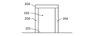
- the shape of the reflector 20 when viewed from the direction in which the passage 101 extends is two I-shapes in the case of the pair of reflectors 20, but the shape is not particularly limited.
- the reflector 20 may be arranged so that the reflector 20 is located on at least one of both sides of the photographing space 102, and the shape of the reflector 20 when viewed from the direction in which the passage 101 extends is I-shaped, J. It may be in the shape of a character, an L shape, a U shape, a C shape, a frame shape, an annular shape, or the like.
- the photographing apparatus 10 may further include a reflector other than the pair of reflectors 20, or may include one reflector having a shape in which the ends of the pair of reflectors 20 are extended and connected. ..
- the photographing device 10 may be provided with at least one reflector 20, and may be provided with, for example, only one of the pair of reflectors 20.
- the photographing device 10 is thinner and smaller than the case where a member such as a spherical mirror that concentrates the sub-terahertz wave on the person 100 is used for reflecting the sub-terahertz wave. It is possible to make it.
- the reflection member 21 is a sheet-like member that diffusely reflects subterahertz waves.
- the reflective member 21 is located between the covering member 24 and the covering member 27.
- the reflective member 21 has two main surfaces 22 and 23 as two surfaces that are front surfaces when viewed from the thickness direction of the reflective member 21.
- the main surface 22 and the main surface 23 are uneven surfaces that diffusely reflect subterahertz waves.
- the main surface 22 is located on the photographing space 102 side of the reflective member 21, and the main surface 23 is located on the side opposite to the photographing space 102 side of the reflective member 21. Both the two main surfaces 22 and the main surface 23 of the reflective member 21 are covered with the covering member 24 and the covering member 27, respectively.
- the average length RSm of the roughness curve element is equal to or higher than the wavelength of the sub-terahertz wave emitted from the first light source 41 and the second light source 42.
- the average length RSm of the roughness curve element may be 0.15 mm or more, and may be 0.3 mm or more.
- the sub-terahertz wave is efficiently diffusely reflected on the main surface 22 and the main surface 23.
- the uneven shapes of the main surface 22 and the main surface 23 are the same.
- the uneven shape of the main surface 22 and the main surface 23 may be different.
- the main surface 22 on the photographing space 102 side of the reflective member 21 may be an uneven surface, and the main surface 23 may be a flat surface.
- the reflective member 21 is composed of a conductive member such as a metal or a conductive oxide.
- the metal include pure metals (single metals) containing at least one metal such as copper, aluminum, nickel, iron, stainless steel, silver, gold and platinum, and alloys.
- the conductive oxide for example, ITO (Indium Tin Oxide), IZO (InZnO; Indium Zinc Oxide), AZO (AlZnO: Aluminum Zinc Oxide), FTO (Florine-doped Tin Oxide), SnO 2, TiO 2 and ZnO Examples thereof include transparent conductive oxides such as 2.
- the covering member 27 is located on the side opposite to the photographing space 102 side of the reflective member 21 and covers the main surface 23.
- the surface of the covering member 27 located on the side opposite to the reflecting member 21 side of the covering member 27 constitutes the outer surface 28 of the reflector 20.
- the outer side surface 28 is a flat surface having no uneven shape like the main surface 23. This makes it easier to clean the reflector 20.
- the material of the covering member 24 and the covering member 27 may be any material that can be processed into the shape of the covering member 24 and the covering member 27 and can maintain the shape.
- a resin material or the like is used as the material of the covering member 24 and the covering member 27, for example.
- the resin material may be, for example, a transparent amorphous resin material that transmits visible light, or a crystalline resin material that diffusely reflects visible light.
- the sub-terahertz wave incident on the reflector 20 from the inside of the pair of reflectors 20 penetrates into the covering member 24. , It is diffusely reflected by the main surface 22 of the reflection member 21, and is ejected from the inner side surface 25 toward the photographing space 102 at various angles.
- the pair of reflectors 20 have the same structure and material as each other, for example.
- the pair of reflectors 20 may have different configurations and materials at least one of them.
- the first light source 41 and the second light source 42 are light sources that emit sub-terahertz waves to the reflector 20, respectively. Specifically, each of the first light source 41 and the second light source 42 emits a sub-terahertz wave to at least one inner side surface 25 of the pair of reflectors 20. Further, as shown in FIG. 3, the first light source 41 and the first light source 41 and the second light source 42 are such that a part of the sub-terahertz wave emitted by each of the first light source 41 and the second light source 42 is diffusely reflected by the reflector 20 multiple times. The two light sources 42 emit subterahertz waves to the reflector 20. Further, a part of the sub-terahertz wave emitted by the first light source 41 and the second light source 42 may be directly incident on the person 100.
- the first light source 41 and the second light source 42 emit subterahertz waves, for example, based on the control of the light source control unit 60. Further, the first light source 41 and the second light source 42 may always emit a sub-terahertz wave during use, or may emit a sub-terahertz wave at regular time intervals.
- the first light source 41 and the second light source 42 are supported by, for example, a support member (not shown).
- the first light source 41 and the second light source 42 are realized by, for example, a known sub-terahertz wave generating element and a circuit for supplying a current to the sub-terahertz wave generating element.
- the first light source 41 is located on the front side of the center of the photographing space 102 in the extending direction of the passage 101.
- the center of the photographing space 102 is the center of the space formed by being sandwiched between the reflectors 20.
- the first light source 41 is located in front of the reflector 20 in the extending direction of the passage 101.
- the front in the direction in which the passage 101 extends may be simply referred to as "forward”
- the rear in the direction in which the passage 101 extends may be simply referred to as "rear”.
- "forward” and “backward” do not refer to front and back in the progress of the person 100 in the passage 101, but are terms that refer to relative directions.
- the first light source 41 emits a sub-terahertz wave from the front side of the reflector 20 to the inner surface 25 of the reflector 20.
- the first light source 41 is located near the front end of each of the pair of reflectors 20 and is separated from the reflectors 20. Further, the first light source 41 is located between the first detector 51 and the third detector 53 and the reflector 20. As a result, the first light source 41, the first detector 51, and the third detector 53 are located on the same direction side of the reflector 20, specifically, on the front side. Further, the first light source 41 emits a sub-terahertz wave to the reflector 20 from a position closer to the reflector 20 than the first detector 51 and the third detector 53.
- the sub-terahertz wave diffusely reflected by the reflector 20 after being emitted from the first light source 41 is irradiated to the person 100 without traveling to the first detector 51 side and the third detector 53 side. Therefore, the sub-terahertz wave emitted from the first light source 41 can be efficiently used.
- the first light source 41 may be located, for example, in the photographing space 102, or may be located in front of the first detector 51 and the third detector 53.
- the first light source 41 includes, for example, a point light source that radiates a sub-terahertz wave.
- FIG. 5A is a schematic view showing an example of the case where the first light source 41 is viewed from the front. In FIG. 5A, components other than the first light source 41 and the reflector 20 are omitted.
- the first light source 41 includes a plurality of point light sources 41a that line up along the reflector 20 and radiate a sub-terahertz wave when viewed from the extending direction of the passage 101.
- the plurality of point light sources 41a are arranged along the direction in which the pair of reflectors 20 are erected. In FIG.
- the first light source 41 may include another light source instead of the plurality of point light sources 41a.
- FIG. 5B is a schematic diagram showing another example when the first light source 41 is viewed from the front. In FIG. 5B, components other than the first light source 41 and the reflector 20 are omitted.
- the first light source 41 includes a linear light source 41b that extends along the reflector 20 and radiates a sub-terahertz wave when viewed from the extending direction of the passage 101.
- the line light source 41b extends along the direction in which the pair of reflectors 20 are erected. In FIG.
- one line light source 41b is arranged so as to extend along one front end of the pair of reflectors 20, and extends along the other front end of the pair of reflectors 20.
- One line light source 41b is arranged. That is, the first light source 41 includes a pair of line light sources 41b.
- the number of line light sources 41b arranged so as to extend along the respective front side ends of the pair of reflectors 20 may be two or more.
- the pair of line light sources 41b are arranged symmetrically with respect to the virtual surface P1.
- the line light source 41b may be arranged only on one side of the pair of reflectors 20.
- the first light source 41 is arranged along the reflector 20 when viewed from the extending direction of the passage 101, and is along the plurality of point light sources 41a, each of which radiates a sub-terahertz wave, and the reflector 20. Includes at least one of the linear light sources 41b that extends and radiates subterahertz waves.
- the first light source 41 can emit a wide range of sub-terahertz waves along the reflector 20 when viewed from the extending direction of the passage.
- the person 100 is effectively irradiated with the sub-terahertz wave.
- the second light source 42 is located near the rear end of each of the pair of reflectors 20 and is separated from the reflectors 20. Further, the second light source 42 is located between the second detector 52 and the fourth detector 54 and the reflector 20.
- the second light source 42 may be located, for example, in the photographing space 102, or may be located behind the second detector 52 and the fourth detector 54. Further, when the photographing device 10 does not acquire an image of the surface on the rear side of the person 100, the second light source 42 may not be provided in the photographing device 10.
- the second light source 42 includes, for example, at least one of a point light source and a line light source that radiate a sub-terahertz wave.
- the point light source and the line light source included in the second light source 42 are the same as those of the first light source 41. Therefore, the point light source and the line light source included in the second light source 42 will be described by replacing the first light source 41 with the second light source 42 and replacing the front with the rear from the explanation in FIGS. 5A and 5B.
- the first detector 51 receives the reflected wave of the subterahertz wave diffusely reflected by the reflector 20 by the person 100 after being emitted from the first light source 41.
- the first detector 51 generates an image based on the received reflected wave.
- the first detector 51 outputs the generated image to the image processing unit 90.
- the generation of an image by a detector such as the first detector 51 is also referred to as "shooting".
- the first detector 51 exposes and generates an image at the timing when the first light source 41 emits a sub-terahertz wave.
- the first detector 51 is located on the front side of the center of the photographing space in the extending direction of the passage 101. In the example shown in FIG. 3, the first detector 51 is located in front of the reflector 20 in the extending direction of the passage 101. The first detector 51 captures an image of the front surface of the person 100.
- the first detector 51 is supported, for example, by a support member or the like (not shown).
- the first detector 51 includes an image sensor 55 and an optical system 56.
- the image sensor 55 receives the reflected wave of the subterahertz wave diffusely reflected by the reflector 20 by the person 100 after being emitted from a light source such as the first light source 41.
- the image sensor 55 detects the intensity of the received reflected wave and generates an image based on the detected intensity. Specifically, the image sensor 55 converts an image of a sub-terahertz wave emitted from an object to be photographed into an electric signal according to its intensity during exposure. Then, the image sensor 55 generates an image based on the converted electric signal.
- the image generated by the image sensor 55 is output to the image processing unit 90.
- the sub-terahertz wave is specularly reflected on the human body, metal, etc., and passes through clothes, bags, etc. Therefore, the image sensor 55 receives the reflected wave mirror-reflected by the human 100's body from a region of the human 100's body that is included in the angle range in which the image sensor 55 can receive the wave.
- a reflected wave by the person 100 is incident on the image sensor 55 through the range indicated by the broken line extending from the first detector 51 in FIG.
- the image sensor 55 receives a reflected wave mirror-reflected by the concealed blade from a region included in the angle range in which the image sensor 55 can receive a wave.
- the image sensor 55 is composed of, for example, a plurality of pixels each including a sub-terahertz wave detection element, peripheral circuits, and the like.
- the optical system 56 forms an image of the subterahertz wave diffusely reflected by the reflecting plate 20 on the image sensor 55 after being emitted from a light source such as the first light source 41.
- the optical system 56 includes, for example, at least one lens.
- the first detector 51 may not include the optical system 56, and the reflected wave may be directly incident on the image sensor 55.
- the second detector 52 receives the reflected wave of the subterahertz wave diffusely reflected by the reflector 20 by the person 100 after being emitted from the second light source 42.
- the second detector 52 generates an image based on the received reflected wave.
- the second detector 52 outputs the generated image to the image processing unit 90.
- the second detector 52 exposes and generates an image at the timing when the second light source 42 emits a sub-terahertz wave.
- the second detector 52 is located behind the center of the photographing space 102 in the extending direction of the passage 101. In the example shown in FIG. 3, the second detector 52 is located behind the reflector 20. The second detector 52 captures an image of the rear surface of the person 100.
- the second detector 52 is supported, for example, by a support member or the like (not shown). In this way, by providing the photographing device 10 with the first detector 51 and the second detector 52, it is possible to generate images on both the front and rear sides of the person 100.
- the second detector 52 includes an image sensor 55a and an optical system 56a. Since the image sensor 55a and the optical system 56a are the same as the image sensor 55 and the optical system 56 described above, detailed description thereof will be omitted.
- the second detector 52 may not be provided in the photographing device 10.
- the third detector 53 receives the reflected wave of the subterahertz wave diffusely reflected by the reflector 20 by the person 100 after being emitted from the first light source 41.
- the third detector 53 generates an image based on the received reflected wave.
- the third detector 53 outputs the generated image to the image processing unit 90.
- the third detector 53 exposes and generates an image at the timing when the first light source 41 emits a sub-terahertz wave.
- the third detector 53 is located on the front side of the center of the photographing space 102 in the extending direction of the passage 101. In the example shown in FIG. 3, the third detector 53 is located on the front side of the reflector 20. The third detector 53 is supported, for example, by a support member or the like (not shown). The first detector 51 and the third detector 53 are arranged at different positions in the top view with respect to the passage 101. The first detector 51 and the third detector 53 are different in the incident direction of the reflected wave by the person 100. As a result, the first detector 51 and the third detector 53 generate an image based on the reflected wave from the surface of the person 100 facing in a different direction. Therefore, for example, it is possible to reduce the blind spot when the photographing device 10 detects a dangerous object such as a knife hidden by the person 100.
- the third detector 53 includes an image sensor 55b and an optical system 56b. Since the image sensor 55b and the optical system 56b are the same as the image sensor 55 and the optical system 56 described above, detailed description thereof will be omitted.
- the fourth detector 54 is located behind the center of the photographing space 102 in the extending direction of the passage 101. In the example shown in FIG. 3, the fourth detector 54 is located behind the reflector 20. The fourth detector 54 is supported, for example, by a support member or the like (not shown).
- the positional relationship between the second detector 52 and the fourth detector 54 is the same as the positional relationship between the first detector 51 and the third detector 53.
- the first detector 51 in the description of the positional relationship between the first detector 51 and the third detector 53 is read as the second detector, and the third detector is used. This will be described by replacing the detector 53 with the fourth detector 54.
- the fourth detector 54 includes an image sensor 55c and an optical system 56c. Since the image sensor 55c and the optical system 56c are the same as the image sensor 55 and the optical system 56 described above, detailed description thereof will be omitted.
- the third detector 53 and the fourth detector 54 may not be provided in the photographing device 10.
- the light source control unit 60 controls the emission of the sub-terahertz wave of each of the first light source 41 and the second light source 42.
- the light source control unit 60 controls, for example, the timing at which the sub-terahertz wave is emitted to each of the first light source 41 and the second light source 42.
- the light source control unit 60 emits a sub-terahertz wave to the first light source 41 in the first period and does not emit the sub-terahertz wave to the second light source 42, and the second light source is in a second period different from the first period.
- the sub-terahertz wave is emitted to the 42, and the sub-terahertz wave is not emitted to the first light source 41.
- the light source control unit 60 controls the emission of sub-terahertz waves of each of the first light source 41 and the second light source 42 based on, for example, signals acquired from the shooting control unit 70, the sensor 80, and the like.
- the light source control unit 60 includes, for example, a processor and a memory, and is realized by the processor executing a program stored in the memory.
- the shooting control unit 70 controls the timing at which each detector generates an image.
- the photographing control unit 70 causes the first detector 51 and the third detector 53 to generate an image in synchronization with each other, and causes the second detector 52 and the fourth detector 54 to generate an image in synchronization with each other. Let me. Further, the photographing control unit 70 causes each detector to generate an image based on, for example, the timing of emission of the sub-terahertz wave of each of the first light source 41 and the second light source 42.
- the photographing control unit 70 may cause each detector to generate an image based on the signal from the sensor 80 or the like.
- the photographing control unit 70 includes, for example, a processor and a memory, and is realized by the processor executing a program stored in the memory.
- the sensor 80 is a sensor for detecting the presence of the person 100.
- the sensor 80 outputs a signal indicating the presence of the person 100 to the light source control unit 60 and the photographing control unit 70.
- the sensor 80 is, for example, a camera that captures a moving image.
- the sensor 80 may be another sensor such as a motion sensor.
- the number of sensors 80 included in the photographing device 10 is one in the example shown in FIG. 3, the photographing device 10 may include a plurality of sensors 80.
- the image processing unit 90 receives an image from each detector, it outputs the received image to the outside, performs image processing on the received image, and outputs the result of the image processing to the outside.
- the photographing device 10 does not have to include the image processing unit 90, and the detector may output an image to an external image processing device. Further, the function of the image processing unit 90 may be provided in each detector.
- the irradiation mode of the sub-terahertz wave in the photographing apparatus 10 will be described with reference to FIG.
- the sub-terahertz wave (arrow in FIG. 3) emitted from the light source to the reflector 20 is diffusely reflected by the reflector 20 because the photographing space 102 is covered by the reflector 20 from the side of the photographing space 102. It is incident on the person 100.
- the inner side surface 25 of the reflector 20 functions as a surface light source, and the sub-terahertz wave is irradiated from various angles to a relatively wide range with respect to the person 100. Therefore, the photographing device 10 can effectively irradiate the person 100 with a sub-terahertz wave.
- the sub-terahertz wave emitted from the light source is diffusely reflected by the reflector 20 at least once and reflected by the person 100.
- most of the sub-terahertz waves emitted from the light source to the reflector 20 are repeatedly diffusely reflected in the shooting space 102, so that they stay in the space of the shooting space 102 located on the passage 101 through which the person 100 passes.
- the photographing device 10 can more effectively irradiate the person 100 with the sub-terahertz wave.
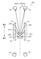
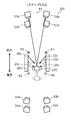
- 6A, 6B, 6C and 6D are diagrams for explaining an operation example of the photographing apparatus 10 according to the present embodiment.
- 6A, 6B, 6C and 6D show views of the photographing apparatus 10 as viewed from above. Further, for ease of viewing, the sensor 80 is not shown in FIGS. 6A, 6B, 6C and 6D. Further, in FIGS.
- the first light source 41 and the second light source 42 are hatched with dots when the sub-terahertz wave is emitted, and the sub-terahertz wave is emitted. If not, the dots are not hatched.
- FIGS. 6A, 6B, 6C, and 6D an example of the course of the sub-terahertz wave emitted from the reflector 20 is schematically shown by a solid arrow. These are also the same in the figure for explaining the operation example in each of the following modified examples.
- step S1 the person 100 enters the shooting space 102 and passes through the rear end of the shooting space 102.
- the light source control unit 60 detects that the person 100 is present at the rear end of the photographing space 102, the light source control unit 60 emits a sub-terahertz wave to the first light source 41.
- the light source control unit 60 detects the presence of the person 100 by receiving, for example, a signal from the sensor 80 indicating that the person 100 is present at the rear end of the photographing space 102. Further, at this time, the light source control unit 60 does not emit the sub-terahertz wave to the second light source 42.
- the sub-terahertz wave emitted from the first light source 41 is diffusely reflected by the reflector 20 at least once, and is irradiated to the person 100 from the inner side surface 25. Specifically, the sub-terahertz wave emitted from the inner side surface 25 located on the front side of the person 100 is irradiated to the person 100.
- the reflected wave of the sub-terahertz wave applied to the human 100 by the human 100 is incident on the first detector 51.
- the first detector 51 receives the reflected wave from the person 100.
- the photographing control unit 70 outputs an image to the first detector 51 based on the reflected wave received by the first detector 51 at the timing when the light source control unit 60 emits the sub-terahertz wave to the first light source 41. Generate.
- step S1 the first detector 51 receives the wave in the first period, which is the period in which the light source control unit 60 emits the sub-terahertz wave to the first light source 41 and does not emit the sub-terahertz wave to the second light source 42.
- the image is generated based on the reflected wave by the person 100. If the second light source 42 emits a sub-terahertz wave when the first detector 51 generates an image, the sub-terahertz wave emitted from the second light source 42 located on the rear side of the person 100 is generated. There is a possibility that the wave reflected by the person 100 will be incident on the first detector 51 at the same time. Therefore, there is a possibility that the image generated by the first detector 51 due to the reflected wave by the person 100 becomes unclear.
- step S2 as in step S1, the first detector 51 generates an image based on the reflected wave by the person 100 who received the wave in the first period.
- the range in which the reflected wave by the person 100 is incident on the first detector 51 is the range indicated by the broken line extending from the first detector 51 in FIG. 6B, and the range is the second range. A part of the light source 42 and the reflector 20 is located. Therefore, when the second light source 42 emits a sub-terahertz wave, the sub-terahertz wave derived from the second light source 42 is particularly likely to be incident on the first detector 51. Therefore, in the first period when the second light source 42 does not emit the sub-terahertz wave, the effect that the image by the reflected wave by the person 100 becomes clear due to the generation of the image by the first detector 51 is remarkable.
- step S1 the light source control unit 60 causes the first light source 41 to emit a sub-terahertz wave until the generation of the image of the first detector 51 in step 2 is completed without turning off the first light source 41. You can leave it alone.
- the photographing control unit 70 detects that the person 100 is present in the central portion of the photographing space 102, the first detector 51 causes the first detector 51 to generate an image.
- step S3 the light source control unit 60 emits a sub-terahertz wave to the second light source 42.
- the light source control unit 60 emits a sub-terahertz wave to the second light source 42 immediately after the completion of the exposure in the image generation by the first detector 51 in step S2.
- the light source control unit 60 acquires, for example, a signal indicating the timing at which the image generation by the first detector 51 ends, via the imaging control unit 70.
- the signal is, for example, a signal indicating the end of exposure of the image sensor 55. Further, at this time, the light source control unit 60 does not emit the sub-terahertz wave to the first light source 41.
- the sub-terahertz wave emitted from the second light source 42 is diffusely reflected by the reflector 20 at least once, and is irradiated to the person 100 from the inner side surface 25. Specifically, the sub-terahertz wave emitted from the inner side surface 25 located on the rear side of the person 100 is irradiated to the person 100.
- the reflected wave of the sub-terahertz wave applied to the human 100 by the human 100 is incident on the second detector 52.
- the second detector 52 receives the reflected wave from the person 100.
- step S2 and step S3 the imaging by the first detector 51 and the imaging by the second detector 52 are performed without a time interval.
- the person 100 can be photographed from both the front and back sides without a time interval, so that the area of the body of the person 100 that is not photographed at the time of photographing is reduced, and the photographing device 10 is used for detecting dangerous objects hidden by the person 100.
- the accuracy of detection can be improved.
- the second detector 52 receives the wave in the second period, which is the period in which the light source control unit 60 emits the sub-terahertz wave to the second light source 42 and does not emit the sub-terahertz wave to the first light source 41.
- the image is generated based on the reflected wave by the person 100. If the first light source 41 emits a sub-terahertz wave when the second detector 52 generates an image, the sub-terahertz wave emitted from the first light source 41 located on the front side of the person 100 is generated. There is a possibility that the wave reflected by the person 100 will be incident on the second detector 52 at the same time. Therefore, there is a possibility that the image generated by the second detector 52 due to the reflected wave by the person 100 becomes unclear.
- step S3 the second detector 52 generates an image based on the reflected wave by the person 100 who received the wave in the second period when the first light source 41 does not emit the sub-terahertz wave.
- the image due to the reflected wave by the person 100 becomes clear.
- the range in which the reflected wave by the person 100 is incident on the second detector 52 is the range indicated by the broken line extending from the second detector 52 in FIG. 6C, and the range is the first. A part of the light source 41 and the reflector 20 is located. Therefore, when the second light source 42 emits a sub-terahertz wave, the sub-terahertz wave derived from the first light source 41 is particularly likely to be incident on the second detector 52. Therefore, in the second period when the first light source 41 does not emit the sub-terahertz wave, the effect that the image by the reflected wave by the person 100 becomes clear due to the generation of the image by the second detector 52 is remarkable.
- the detector that first generates an image may be the second detector 52 instead of the first detector 51. That is, in the description of step S2 and step S3, the operation of exchanging the first light source 41 and the second light source 42 and exchanging the first detector 51 and the second detector 52 may be performed.
- step S4 the person 100 advances forward from the position in step S3 and is located at the front end of the photographing space 102. That is, the person 100 passes through the front end of the photographing space 102.
- the light source control unit 60 detects that the person 100 is present at the front end of the photographing space 102
- the light source control unit 60 emits a sub-terahertz wave to the second light source 42.
- the light source control unit 60 detects the presence of the person 100 by receiving, for example, a signal from the sensor 80 indicating that the space 102 is present at the front end portion of the photographing space 102. Further, at this time, the light source control unit 60 does not emit the sub-terahertz wave to the first light source 41.
- the sub-terahertz wave emitted from the second light source 42 is diffusely reflected by the reflector 20 at least once, and is irradiated to the person 100 from the inner side surface 25.
- the reflected wave of the sub-terahertz wave applied to the human 100 by the human 100 is incident on the second detector 52.
- the second detector 52 receives the reflected wave from the person 100.
- the photographing control unit 70 generates an image on the second detector 52 based on the reflected wave received by the second detector 52 at the timing when the light source control unit 60 emits the sub-terahertz wave to the second light source 42. Let me. That is, the second detector 52 generates an image based on the reflected wave by the person 100 passing through the front end portion of the photographing space 102.
- the second detector 52 captures an image of the rear surface of the person 100.
- the second detector 52 outputs the generated image to the image processing unit 90.
- the light source control unit 60 detects, for example, that the image generation by the second detector 52 is completed, and turns off the second light source 42.
- step S4 similarly to step S3, the second detector 52 generates an image based on the reflected wave by the person 100 who received the wave in the second period. Therefore, as in step S3, the effect that the image due to the reflected wave by the person 100 becomes clear can be obtained.
- the photographing control unit 70 operates, for example, the first detector 51 and the third detector 53 in synchronization with the second detector 52 and the fourth detector 54.
- the third detector 53 operates in the same manner as the first detector 51
- the fourth detector 54 operates in the same manner as the second detector 52. Therefore, the operation of the third detector 53 and the fourth detector 54 will be described by replacing the first detector 51 with the third detector 53 and replacing it with the second detector 52.
- each detector generated an image of the person 100 at the positions shown in FIGS. 6A, 6B, 6C and 6D, but the position of the person 100 is at these positions. Not exclusively.
- the position of the person 100 when the detector generates an image of the person 100 may be, for example, a position where the inner side surface 25 can emit a sub-terahertz wave to the person 100 from the detector side.
- the position where the person 100 is photographed in steps S2 and S3 is a position where the sub-terahertz wave can be emitted to the person 100 from the inner side surface 25 located on either the front side or the rear side of the person 100. be.
- the position where the person 100 is photographed in steps S2 and S3 is, for example, the central portion of the photographing space 102 in the direction in which the passage 101 extends, as described above.
- each detector continuously generates images, and selects an image generated at the timing in steps S1 to S4 from a plurality of continuously generated images. Therefore, it may be output to the image processing unit 90. Further, each detector may continuously generate images and output all of the continuously generated images to the image processing unit 90. In this case, the image processing unit 90 selects, for example, an image generated at the timing in steps S1 to S4 from among the plurality of received images, and performs image processing on the selected image.
- the imaging device according to the first modification of the embodiment performs imaging by the first detector and imaging by the second detector without a time interval. Is mainly different in that is performed multiple times.
- the photographing apparatus according to the first modification of the embodiment has a length of the reflector in the direction in which the passage extends, and the first detector and the second detector, as compared with the photographing apparatus according to the embodiment. The distance is getting longer.
- the differences from the embodiments will be mainly described, and the common points will be omitted or simplified.
- FIG. 7 is a schematic view of the photographing apparatus 10a according to this modified example when viewed from above.
- the photographing apparatus 10a is configured to include a reflecting plate 20a instead of the reflecting plate 20 of the photographing apparatus 10.
- the configuration of the photographing device 10a other than the reflector 20a is the same as that of the photographing device 10.
- the reflector 20a covers the photographing space 102 on the passage 101 through which the person 100 passes from at least one of both sides of the passage 101.
- the reflector 20a sandwiches the photographing space 102 on the passage 101 through which the person 100 passes from both sides of the passage 101.
- the pair of reflectors 20a stand upright from the floor surfaces on both sides of the passage 101 through which the person 100 passes and face each other.
- the pair of reflectors 20a each have an inner surface 25a and an outer surface 28a as two surfaces that are front surfaces when viewed from the thickness direction of the reflector 20a.
- the reflector 20a has the same configuration as the reflector 20 except that the length of the reflector 20a is longer than that of the reflector 20 in the extending direction of the passage 101, and detailed description thereof will be omitted.
- step S11 the person 100 enters the shooting space 102 and passes through the rear side of the shooting space 102.
- the light source control unit 60 detects that the person 100 exists on the rear side in the photographing space 102, the light source control unit 60 emits a sub-terahertz wave to the first light source 41. Further, at this time, the light source control unit 60 does not emit the sub-terahertz wave to the second light source 42.
- the sub-terahertz wave emitted from the first light source 41 is diffusely reflected by the reflector 20a at least once, and is irradiated to the person 100 from the inner side surface 25a. Since the subsequent operations of the photographing apparatus 10a are the same as those in step S2, detailed description thereof will be omitted. As a result, the first detector 51 generates an image based on the reflected wave by the person 100 passing through the rear side in the photographing space 102.
- the sub-terahertz wave emitted from the second light source 42 is diffusely reflected by the reflector 20a at least once, and is irradiated to the person 100 from the inner side surface 25a. Since the subsequent operations of the photographing apparatus 10a are the same as those in step S3, detailed description thereof will be omitted.
- the photographing control unit 70 causes the second detector 52 to start the exposure in the image generation immediately after the exposure in the image generation by the first detector 51 in step S11 is completed. That is, the second detector 52 captures an image of the rear surface of the person 100 immediately after the image is captured by the first detector 51 in step S11.
- step S14 immediately after step S13, as shown in FIG. 8D, the light source control unit 60 causes the second light source 42 to emit a sub-terahertz wave. Specifically, the light source control unit 60 emits a sub-terahertz wave to the second light source 42 immediately after the completion of the exposure in the image generation by the first detector 51 in step S13.
- the sub-terahertz wave emitted from the second light source 42 is diffusely reflected by the reflector 20a at least once, and is irradiated to the person 100 from the inner side surface 25a. Since the subsequent operations of the photographing apparatus 10a are the same as those in step S3, detailed description thereof will be omitted.
- the photographing control unit 70 causes the second detector 52 to start the exposure in the image generation immediately after the exposure in the image generation by the first detector 51 in step S13 is completed. That is, the second detector 52 captures an image of the rear surface of the person 100 immediately after the image is captured by the first detector 51 in step S13.
- step S11 and step S12 the imaging by the first detector 51 and the imaging by the second detector 52 are performed without a time interval. Further, also in steps S13 and S14, the shooting by the first detector 51 and the shooting by the second detector 52 are performed without a time interval.
- steps S13 and S14 the shooting by the first detector 51 and the shooting by the second detector 52 are performed without a time interval.
- the person 100 can be photographed from both front and back sides a plurality of times without a time interval, and while the person 100 passes through the photographing space 102, the person can be photographed. Images of a plurality of 100 aspects are generated. Therefore, the detection accuracy when the photographing device 10a is used for detecting a dangerous object hidden by the person 100 can be further improved.
- steps S11 and S12 since the front and rear surfaces of the person 100 are photographed at the same position of the person 100, in order to irradiate the person 100 with a sub-terahertz wave equivalent to the operation example of the embodiment, Reflectors 20a need to be located on both front and rear sides of the person 100. The same applies to steps S13 and S14. Therefore, in order to photograph the person 100 from both the front and rear sides a plurality of times without deteriorating the image quality of the image to be photographed, the length of the reflector 20a is larger than that of the reflector 20. , The length of the surface for emitting the sub-terahertz wave to the person 100 becomes longer.
- the photographing apparatus when the first detector and the second detector are each located at a predetermined position as compared with the photographing apparatus according to the embodiment.
- the main difference is that the image is taken.
- the photographing apparatus according to the second modification of the embodiment has a length of the reflector in the direction in which the passage extends, and the first detector and the second detector, as compared with the photographing apparatus according to the embodiment. The distance is getting shorter.
- the differences from the embodiments will be mainly described, and the common points will be omitted or simplified.
- FIG. 9 is a schematic view of the photographing apparatus 10b according to this modified example when viewed from above.
- the photographing apparatus 10b is configured to include a reflecting plate 20b instead of the reflecting plate 20 of the photographing apparatus 10.
- the configuration of the photographing device 10b other than the reflector 20b is the same as that of the photographing device 10.
- the reflector 20b covers the photographing space 102 on the passage 101 through which the person 100 passes from at least one of both sides of the passage 101.
- the reflector 20b sandwiches the photographing space 102 on the passage 101 through which the person 100 passes from both sides of the passage 101.
- the pair of reflectors 20b stand upright from the floor surfaces on both sides of the passage 101 through which the person 100 passes and face each other.
- the pair of reflectors 20b each have an inner surface 25b and an outer surface 28b as two surfaces that are front surfaces when viewed from the thickness direction of the reflector 20b.
- the reflector 20b has the same configuration as the reflector 20 except that the length of the reflector 20b is shorter than that of the reflector 20 in the extending direction of the passage 101, and detailed description thereof will be omitted.
- step S22 the person 100 advances forward from the position in step S21 and is located at the front end of the photographing space 102. That is, the person 100 passes through the front end of the photographing space 102.
- the light source control unit 60 detects that the person 100 is present at the front end of the photographing space 102, the light source control unit 60 emits a sub-terahertz wave to the second light source 42. Further, at this time, the light source control unit 60 does not emit the sub-terahertz wave to the first light source 41.
- the sub-terahertz wave emitted from the second light source 42 is diffusely reflected by the reflector 20b at least once, and is irradiated to the person 100 from the inner side surface 25b. Since the subsequent operations are the same as those in step S4, detailed description thereof will be omitted. As a result, the second detector 52 generates an image based on the reflected wave by the person 100 passing through the front end portion of the photographing space 102.
- the first detector 51 generates an image based on the reflected wave by the person 100 passing through the rear end of the photographing space 102 in the direction in which the passage 101 extends. ..
- the second detector 52 generates an image based on the reflected wave by the person 100 passing through the front end portion of the photographing space 102 in the direction in which the passage 101 extends. In this way, images of the person 100 are taken at both ends of the shooting space 102. Therefore, even when both the image of the front surface of the person 100 and the image of the rear surface of the person 100 are taken, the sub-terahertz on both sides of the front and rear of the person 100 in the extending direction of the passage 101.
- step S21 the first detector 51 does not perform imaging before and after the person 100 moves from the rear end to the center of the imaging space 102 as in steps S1 to S2 described above. Shooting is performed when the person 100 is located at the rear end of the shooting space 102. Therefore, the length of the reflector 20b can be made shorter than the length of the reflector 20 by the length that the person 100 moves from step S1 to step S2 in the extending direction of the passage 101.
- the subterahertz wave emission operation by the light source in the photographing apparatus 10b is not limited to the above operation example.
- the photographing apparatus 10b may be a light source that does not include a light source control unit 60 and that the first light source 41 and the second light source 42 emit subterahertz waves at all times or at regular intervals during use.
- the range in which the reflected wave from the person 100 is incident on the first detector 51 is the range indicated by the broken line extending from the first detector 51 in FIG. 10A, and the second light source 42 is in the range.
- the reflector 20b is not located.
- the first detector 51 is a second light source within an angle range in which the person 100 can receive the reflected wave by the person 100 in the first detector 51 when the person 100 is located at the rear end of the photographing space 102. It is arranged in a positional relationship so that the 42 and the reflector 20b do not enter.
- the range in which the reflected wave by the person 100 is incident on the second detector 52 is the range indicated by the broken line extending from the second detector 52 in FIG. 1
- the light source 41 and the reflector 20b are not located. That is, the second detector 52 is the first light source 41 within an angle range in which the person 100 can receive the reflected wave by the person 100 in the second detector 52 when the person 100 is located at the front end of the photographing space.
- step S21 and step S22 even if the first light source 41 and the second light source 42 simultaneously emit subterahertz waves, the person 100 of the image generated by the first detector 51 and the second detector 52 The image due to the reflected wave is less likely to be blurred.
- the imaging device according to the third modification of the embodiment passes through a person whose detector is located in front of and behind the reflector and a photographing space as compared with the imaging device according to the embodiment.
- the main difference is that it produces images of people.
- the photographing apparatus according to the third modification of the embodiment is provided with a plurality of detectors as compared with the photographing apparatus according to the embodiment.
- the photographing apparatus according to the third modification of the embodiment has a length of the reflector in the direction in which the passage extends, and the first detector and the second detector, as compared with the photographing apparatus according to the embodiment. The distance is getting shorter.
- the differences from the embodiments will be mainly described, and the common points will be omitted or simplified.
- FIG. 11 is a schematic view of the photographing apparatus 10c according to this modified example when viewed from above.
- the photographing apparatus 10c includes a reflecting plate 20c instead of the reflecting plate 20 of the photographing apparatus 10, and the first detector 51, the second detector 52, and the third detector of the photographing apparatus 10 are provided.
- 53 and the fourth detector 54 a plurality of first detectors 51a, 51b, a plurality of second detectors 52a, 52b, a plurality of third detectors 53a, 53b and a plurality of fourth detectors 54a, 54b. It is a configuration including.
- the plurality of first detectors 51a and 51b other than the reflector 20c, the plurality of first detectors 51a and 51b, the plurality of second detectors 52a and 52b, the plurality of third detectors 53a and 53b and the plurality of fourth detectors 54a and 54b.
- the configuration is the same as that of the photographing apparatus 10.
- the reflector 20c covers the photographing space 102 on the passage 101 through which the person 100 passes from at least one of both sides of the passage 101.
- the reflector 20c sandwiches the photographing space 102 on the passage 101 through which the person 100 passes from both sides of the passage 101.
- the pair of reflectors 20c stand upright from the floor surfaces on both sides of the passage 101 through which the person 100 passes and face each other.
- the pair of reflectors 20c each have an inner surface 25c and an outer surface 28c as two surfaces that are front surfaces when viewed from the thickness direction of the reflector 20c.
- the reflector 20c has the same configuration as the reflector 20 except that the length of the reflector 20c is shorter than that of the reflector 20 in the extending direction of the passage 101, and detailed description thereof will be omitted.
- the plurality of second detectors 52a and 52b are located behind the reflector 20c in the extending direction of the passage 101, respectively.
- the second detector 52a and the second detector 52b are arranged in this order along the direction in which the passage 101 extends from the side far from the reflector 20c, that is, the rear side.
- the plurality of second detectors 52a and 52b include an image sensor 55a and an optical system 56a, respectively, similarly to the second detector 52.
- the plurality of third detectors 53a and 53b are located in front of the reflector 20c in the extending direction of the passage 101, respectively.
- the third detector 53a and the third detector 53b are arranged in this order along the direction in which the passage 101 extends from the side far from the reflector 20c, that is, the front side.
- the plurality of third detectors 53a and 53b include an image sensor 55b and an optical system 56b, respectively, like the third detector 53.
- the plurality of fourth detectors 54a and 54b are located behind the reflector 20c in the extending direction of the passage 101, respectively.
- the fourth detector 54a and the fourth detector 54b are arranged in this order along the direction in which the passage 101 extends from the side far from the reflector 20c, that is, the rear side.
- the plurality of fourth detectors 54a and 54b include an image sensor 55c and an optical system 56c, respectively, similarly to the fourth detector 54.
- 12A, 12B, 12C and 12D are diagrams for explaining an operation example of the photographing apparatus 10c according to the present modification.
- step S31 the person 100 advances toward the photographing space 102 and is located behind the reflector 20c.
- the light source control unit 60 detects that the person 100 is located behind the reflector 20c, the light source control unit 60 emits a sub-terahertz wave to the first light source 41.
- the light source control unit 60 detects the presence of the person 100 by receiving, for example, a signal from the sensor 80 indicating that the person 100 is present on the rear side of the reflector 20c. Further, at this time, the light source control unit 60 does not emit the sub-terahertz wave to the second light source 42.
- the sub-terahertz wave emitted from the first light source 41 is diffusely reflected by the reflector 20c at least once, and is irradiated to the person 100 from the inner side surface 25c.
- the reflected wave of the sub-terahertz wave applied to the human 100 by the human 100 is incident on the first detector 51b.
- the first detector 51b receives the reflected wave by the person 100.
- the photographing control unit 70 outputs an image to the first detector 51b based on the reflected wave received by the first detector 51b at the timing when the light source control unit 60 emits the sub-terahertz wave to the first light source 41. Generate.
- the first detector 51b generates an image of the front surface of the person 100.
- the first detector 51b outputs the generated image to the image processing unit 90.
- the light source control unit 60 detects, for example, that the image generation by the first detector 51b is completed, and turns off the first light source 41.
- step S32 the person 100 advances forward from the position in step S31, enters the shooting space 102, and is located at the rear end of the shooting space 102. .. That is, the person 100 passes through the rear end of the photographing space 102.
- the light source control unit 60 detects that the person 100 is present at the rear end of the photographing space 102, the light source control unit 60 emits a sub-terahertz wave to the first light source 41. Further, at this time, the light source control unit 60 does not emit the sub-terahertz wave to the second light source 42.
- the sub-terahertz wave emitted from the first light source 41 is diffusely reflected by the reflector 20c at least once, and is irradiated to the person 100 from the inner side surface 25c.
- the reflected wave of the sub-terahertz wave applied to the human 100 by the human 100 is incident on the first detector 51a.
- the first detector 51a receives the reflected wave by the person 100.
- the photographing control unit 70 outputs an image to the first detector 51a based on the reflected wave received by the first detector 51a at the timing when the light source control unit 60 emits the sub-terahertz wave to the first light source 41. Generate.
- the first detector 51a generates an image based on the reflected wave by the person 100 passing through the rear end portion of the photographing space 102. As a result, the first detector 51a generates an image of the front surface of the person 100. The first detector 51a outputs the generated image to the image processing unit 90.
- the light source control unit 60 detects, for example, that the image generation by the first detector 51a is completed, and turns off the first light source 41.
- the plurality of first detectors 51a and 51b are the reflected wave by the person 100 located behind the reflector 20c in the extending direction of the passage 101, and the photographing space.
- a plurality of images are generated based on each of the reflected waves by the person 100 passing through 102.
- the photographing device 10c generates an image of the person 100 even before the person 100 enters the photographing space 102, so that the length of the reflector 20c in the direction in which the passage 101 extends can be shortened.
- the photographing device 10c can be miniaturized.
- the person 100 may feel a feeling of blockage because it is sandwiched between the reflectors 20c when passing through the photographing space 102, but the length of the reflector 20c is shortened, so that the person 100 is blocked. The feeling is reduced.
- the length of the reflector 20c can be shorter than the length of the reflector 20b by the length that the person 100 moves from step S31 to step S32.
- step S31 and step S32 by changing the detectors that generate images to the first detector 51a and the first detector 51b in which the passage 101 is arranged in the extending direction, the incident on the same detector is obtained. An image is taken based on the reflected wave at an angle.
- step S31 and step S32 the angle range of the sub-terahertz wave incident on the person 100 is narrower than that in the case of the operation example (for example, step S1) of the above-described embodiment.
- the angle range of the sub-terahertz wave incident on the person 100 is different between step S31 and step S32, an image of the sub-terahertz wave incident on the person 100 based on the reflected wave by the person 100 is taken.
- step S31 a sub-terahertz wave having a relatively small inclination with respect to the inner surface 25c is incident on the person 100
- step S32 a sub-terahertz wave having a relatively large inclination with respect to the inner surface 25c is incident on the person 100. ..
- the surface of the person 100 to be photographed is different in the plurality of images to be photographed, and it is possible to suppress a decrease in the detection accuracy when the photographing device 10c is used for detecting a dangerous object or the like hidden by the person.
- the first detector 51a and the first detector 51b are arranged apart from each other by the length of movement of the person 100 from step S31 to step S32, so that the first detection of the reflected wave by the person 100 is performed.
- the angle of incidence on the device 51a and the first detector 51b is the same.
- the reflected wave derived from the different gradient of the sub-terahertz wave incident on the person 100 is directed toward the detector. reflect. That is, in step S31 and step S32, the sub-terahertz wave incident on the person 100 having a different inclination with respect to the inner surface 25c is reflected toward the detector.
- the image processing unit 90 may perform image processing for synthesizing the image generated by the first detector 51b in step S31 and the image generated by the first detector 51a in step S32.
- step S33 the person 100 advances forward from the position in step S32 and is located at the front end of the photographing space 102. That is, the person 100 passes through the front end of the photographing space 102.
- the light source control unit 60 detects that the person 100 is present at the front end of the photographing space 102, the light source control unit 60 emits a sub-terahertz wave to the second light source 42. Further, at this time, the light source control unit 60 does not emit the sub-terahertz wave to the first light source 41.
- the second detector 52a generates an image based on the reflected wave by the person 100 passing through the front end portion of the photographing space 102. As a result, the second detector 52a captures an image of the rear surface of the person 100. The second detector 52a outputs the generated image to the image processing unit 90.
- the light source control unit 60 detects, for example, that the image generation by the second detector 52a is completed, and turns off the second light source 42.
- the reflectors 20, 20a, 20b, and 20c have a flat plate shape, but the present invention is not limited to this. At least a part of the reflectors 20, 20a, 20b, and 20c may be curved.
- the reflectors 20, 20a, 20b, and 20c may be, for example, curved so that at least one of the upper side, the front side, and the rear side of the pair of reflectors 20 approaches each other. Further, the reflectors 20, 20a, 20b, and 20c may be divided into a plurality of pieces.
- the sub-terahertz wave incident on the shooting space 102 is suppressed from being emitted from above the shooting space 102, so that the sub-terahertz wave tends to stay in the shooting space 102.
- the three reflectors 20d may be provided in the photographing apparatus 10, 10a, 10b, 10c instead of the pair of reflectors 20, 20a, 20b, 20c.
- the photographing devices 10, 10a, 10b, and 10c may not include the light source control unit 60, the photographing control unit 70, and the sensor 80.
- the photographing devices 10, 10a, 10b, and 10c include an operation receiving unit that receives an operation from the user, photograph a person 100 based on the operation from the user, and perform an operation example of the above-described embodiment and each modification. You may perform the operation of.
- the object to be photographed is 100 people, but the subject is not limited to this.
- the object to be photographed may be luggage or the like.
- the photographing devices 10, 10a, 10b, and 10c do not have to be provided with the photographing control unit 70.
- each detection is performed in the photographing devices 10, 10a, 10b, and 10c.
- the device may have the function of the photographing control unit 70.
- each detector may output a plurality of continuously generated images to the image processing unit 90 without controlling the timing of image generation.
- the photographing devices 10, 10a, 10b, and 10c may not include the sensor 80.
- the light source control unit 60 and the photographing control unit 70 may include the photographing device 10. Signals may be acquired from an external sensor such as a camera provided around 10a, 10b, and 10c.
- the photographing apparatus 10 may not include all of the components described in the above-described embodiment and each modification, and may be composed of only the components for performing the desired operation.
- each component such as the light source control unit 60, the shooting control unit 70, and the image processing unit 90 is composed of dedicated hardware or executes a software program suitable for each component. It may be realized by.
- Each component may be realized by a program execution unit such as a CPU or a processor reading and executing a software program recorded on a recording medium such as a hard disk or a semiconductor memory.
- the order of a plurality of processes in the operation of the photographing apparatus described in the above embodiment is an example.
- the order of the plurality of processes may be changed, and the plurality of processes may be executed in parallel.
- This disclosure can be widely used as a photographing device for photographing an object.
Landscapes
- Engineering & Computer Science (AREA)
- Remote Sensing (AREA)
- Radar, Positioning & Navigation (AREA)
- Physics & Mathematics (AREA)
- Computer Networks & Wireless Communication (AREA)
- General Physics & Mathematics (AREA)
- Electromagnetism (AREA)
- Investigating Or Analysing Materials By Optical Means (AREA)
Priority Applications (4)
| Application Number | Priority Date | Filing Date | Title |
|---|---|---|---|
| CN202080102015.2A CN115836208A (zh) | 2020-06-19 | 2020-12-17 | 摄影装置 |
| JP2022532250A JP7603239B2 (ja) | 2020-06-19 | 2020-12-17 | 撮影装置 |
| EP20940482.1A EP4170319A1 (en) | 2020-06-19 | 2020-12-17 | Photography device |
| US18/079,162 US12366651B2 (en) | 2020-06-19 | 2022-12-12 | Imaging apparatus |
Applications Claiming Priority (2)
| Application Number | Priority Date | Filing Date | Title |
|---|---|---|---|
| JP2020106524 | 2020-06-19 | ||
| JP2020-106524 | 2020-06-19 |
Related Child Applications (1)
| Application Number | Title | Priority Date | Filing Date |
|---|---|---|---|
| US18/079,162 Continuation US12366651B2 (en) | 2020-06-19 | 2022-12-12 | Imaging apparatus |
Publications (1)
| Publication Number | Publication Date |
|---|---|
| WO2021255964A1 true WO2021255964A1 (ja) | 2021-12-23 |
Family
ID=79267686
Family Applications (1)
| Application Number | Title | Priority Date | Filing Date |
|---|---|---|---|
| PCT/JP2020/047285 Ceased WO2021255964A1 (ja) | 2020-06-19 | 2020-12-17 | 撮影装置 |
Country Status (5)
| Country | Link |
|---|---|
| US (1) | US12366651B2 (https=) |
| EP (1) | EP4170319A1 (https=) |
| JP (1) | JP7603239B2 (https=) |
| CN (1) | CN115836208A (https=) |
| WO (1) | WO2021255964A1 (https=) |
Cited By (6)
| Publication number | Priority date | Publication date | Assignee | Title |
|---|---|---|---|---|
| JPWO2022219833A1 (https=) * | 2021-04-15 | 2022-10-20 | ||
| JP2023047720A (ja) * | 2021-09-27 | 2023-04-06 | キヤノン株式会社 | 検査システム、検査システムの制御方法、プログラムおよび記憶媒体 |
| JP2023088041A (ja) * | 2021-12-14 | 2023-06-26 | キヤノン株式会社 | 照明装置、制御方法およびプログラム |
| JP2023113341A (ja) * | 2022-02-03 | 2023-08-16 | キヤノン株式会社 | 撮像システム、撮像システムの制御方法、プログラム、及び記録媒体 |
| WO2023189876A1 (ja) * | 2022-03-29 | 2023-10-05 | パナソニックIpマネジメント株式会社 | 撮影装置 |
| WO2023189875A1 (ja) * | 2022-03-29 | 2023-10-05 | パナソニックIpマネジメント株式会社 | 撮影装置 |
Families Citing this family (1)
| Publication number | Priority date | Publication date | Assignee | Title |
|---|---|---|---|---|
| JP7706918B2 (ja) * | 2021-04-06 | 2025-07-14 | キヤノン株式会社 | 検出システムおよび画像形成装置 |
Citations (5)
| Publication number | Priority date | Publication date | Assignee | Title |
|---|---|---|---|---|
| JP2008509385A (ja) * | 2004-08-04 | 2008-03-27 | カウンシル フォー ザ セントラル ラボラトリー オブ ザ リサーチ カウンシルズ | 走査型撮像装置 |
| US20090294704A1 (en) * | 2005-06-08 | 2009-12-03 | Eitan Zailer | Active millimeter wave imaging system and method |
| US20130307714A1 (en) * | 2012-05-03 | 2013-11-21 | MVT Equity, LLC | Passive Millimeter Wave Imaging System with Environmental Control for Concealed Object Detection |
| EP3287816A1 (en) * | 2016-08-25 | 2018-02-28 | Nuctech Company Limited | Millimeter-wave imaging system |
| JP2018087725A (ja) | 2016-11-28 | 2018-06-07 | キヤノン株式会社 | 画像取得装置、これを用いた画像取得方法及び照射装置 |
Family Cites Families (5)
| Publication number | Priority date | Publication date | Assignee | Title |
|---|---|---|---|---|
| RU2237267C2 (ru) * | 2001-11-26 | 2004-09-27 | Волков Леонид Викторович | Способ формирования изображений в миллиметровом и субмиллиметровом диапазоне волн (варианты) и система формирования изображений в миллиметровом и субмиллиметровом диапазоне волн |
| US7298318B2 (en) * | 2004-11-24 | 2007-11-20 | Agilent Technologies, Inc. | System and method for microwave imaging using programmable transmission array |
| JP2020204513A (ja) * | 2019-06-17 | 2020-12-24 | 株式会社東芝 | システム及び検査方法 |
| CN111103583B (zh) * | 2019-07-04 | 2023-03-21 | 徐立 | 一种具有实时校准的三维射频成像系统和方法 |
| WO2021070428A1 (ja) | 2019-10-09 | 2021-04-15 | パナソニックIpマネジメント株式会社 | 撮影装置 |
-
2020
- 2020-12-17 WO PCT/JP2020/047285 patent/WO2021255964A1/ja not_active Ceased
- 2020-12-17 CN CN202080102015.2A patent/CN115836208A/zh active Pending
- 2020-12-17 EP EP20940482.1A patent/EP4170319A1/en not_active Withdrawn
- 2020-12-17 JP JP2022532250A patent/JP7603239B2/ja active Active
-
2022
- 2022-12-12 US US18/079,162 patent/US12366651B2/en active Active
Patent Citations (5)
| Publication number | Priority date | Publication date | Assignee | Title |
|---|---|---|---|---|
| JP2008509385A (ja) * | 2004-08-04 | 2008-03-27 | カウンシル フォー ザ セントラル ラボラトリー オブ ザ リサーチ カウンシルズ | 走査型撮像装置 |
| US20090294704A1 (en) * | 2005-06-08 | 2009-12-03 | Eitan Zailer | Active millimeter wave imaging system and method |
| US20130307714A1 (en) * | 2012-05-03 | 2013-11-21 | MVT Equity, LLC | Passive Millimeter Wave Imaging System with Environmental Control for Concealed Object Detection |
| EP3287816A1 (en) * | 2016-08-25 | 2018-02-28 | Nuctech Company Limited | Millimeter-wave imaging system |
| JP2018087725A (ja) | 2016-11-28 | 2018-06-07 | キヤノン株式会社 | 画像取得装置、これを用いた画像取得方法及び照射装置 |
Cited By (8)
| Publication number | Priority date | Publication date | Assignee | Title |
|---|---|---|---|---|
| JPWO2022219833A1 (https=) * | 2021-04-15 | 2022-10-20 | ||
| JP2023047720A (ja) * | 2021-09-27 | 2023-04-06 | キヤノン株式会社 | 検査システム、検査システムの制御方法、プログラムおよび記憶媒体 |
| US12372650B2 (en) | 2021-09-27 | 2025-07-29 | Canon Kabushiki Kaisha | Inspection system and method for controlling the same, and storage medium |
| JP2023088041A (ja) * | 2021-12-14 | 2023-06-26 | キヤノン株式会社 | 照明装置、制御方法およびプログラム |
| JP7793358B2 (ja) | 2021-12-14 | 2026-01-05 | キヤノン株式会社 | 照明装置、制御方法およびプログラム |
| JP2023113341A (ja) * | 2022-02-03 | 2023-08-16 | キヤノン株式会社 | 撮像システム、撮像システムの制御方法、プログラム、及び記録媒体 |
| WO2023189876A1 (ja) * | 2022-03-29 | 2023-10-05 | パナソニックIpマネジメント株式会社 | 撮影装置 |
| WO2023189875A1 (ja) * | 2022-03-29 | 2023-10-05 | パナソニックIpマネジメント株式会社 | 撮影装置 |
Also Published As
| Publication number | Publication date |
|---|---|
| US12366651B2 (en) | 2025-07-22 |
| EP4170319A1 (en) | 2023-04-26 |
| CN115836208A (zh) | 2023-03-21 |
| US20230112817A1 (en) | 2023-04-13 |
| JPWO2021255964A1 (https=) | 2021-12-23 |
| JP7603239B2 (ja) | 2024-12-20 |
Similar Documents
| Publication | Publication Date | Title |
|---|---|---|
| WO2021255964A1 (ja) | 撮影装置 | |
| CN105979165B (zh) | 虚化照片生成方法、装置和移动终端 | |
| JP7561340B2 (ja) | 撮影装置 | |
| JP5821833B2 (ja) | 撮影装置、近赤外光照射装置、およびサンバイザー | |
| WO2012035727A1 (en) | Photoacoustic imaging apparatus and control method thereof | |
| JP5133626B2 (ja) | 表面反射特性測定装置 | |
| US20120200535A1 (en) | System and method for improving machine vision in the presence of ambient light | |
| CN113253356B (zh) | 太赫兹波相机系统和用于控制太赫兹波相机系统的方法 | |
| JP2021099358A (ja) | 放射線画像取得システムおよび放射線画像取得方法 | |
| JPWO2021255964A5 (https=) | ||
| JP2013182062A (ja) | 表示装置および投影装置 | |
| JP2021181925A (ja) | 撮像システム、制御装置、制御方法、プログラム | |
| WO2022234685A1 (ja) | 拡散部材 | |
| JP7614809B2 (ja) | テラヘルツ波カメラシステム、およびテラヘルツ波カメラシステムの制御方法 | |
| WO2022219833A1 (ja) | 撮影装置 | |
| JP2869161B2 (ja) | 赤外線画像装置用反射形チョッパ | |
| EP3351166A1 (en) | Photoacoustic apparatus | |
| JP7603240B2 (ja) | 撮影装置 | |
| US12346495B2 (en) | Tracking system using a differential camera with a co-aligned light source assembly | |
| JP7645452B2 (ja) | 撮影装置 | |
| CN102192787A (zh) | 一种红外成像探测系统 | |
| TW201831884A (zh) | 利用超音波產生擾動區域並生成分層掃描影像之成像系統 | |
| KR20170101665A (ko) | 발 정맥 인증 장치 | |
| CN119316732B (zh) | 景深探测系统、景深探测方法、图像处理方法及电子设备 | |
| US20240230945A1 (en) | Determination device and determination method |
Legal Events
| Date | Code | Title | Description |
|---|---|---|---|
| 121 | Ep: the epo has been informed by wipo that ep was designated in this application |
Ref document number: 20940482 Country of ref document: EP Kind code of ref document: A1 |
|
| ENP | Entry into the national phase |
Ref document number: 2022532250 Country of ref document: JP Kind code of ref document: A |
|
| ENP | Entry into the national phase |
Ref document number: 2020940482 Country of ref document: EP Effective date: 20230119 |
|
| NENP | Non-entry into the national phase |
Ref country code: DE |