WO2021255904A1 - インクジェット記録装置及びプログラム - Google Patents
インクジェット記録装置及びプログラム Download PDFInfo
- Publication number
- WO2021255904A1 WO2021255904A1 PCT/JP2020/023996 JP2020023996W WO2021255904A1 WO 2021255904 A1 WO2021255904 A1 WO 2021255904A1 JP 2020023996 W JP2020023996 W JP 2020023996W WO 2021255904 A1 WO2021255904 A1 WO 2021255904A1
- Authority
- WO
- WIPO (PCT)
- Prior art keywords
- drive
- signal
- control signal
- inkjet recording
- drive signal
- Prior art date
- Legal status (The legal status is an assumption and is not a legal conclusion. Google has not performed a legal analysis and makes no representation as to the accuracy of the status listed.)
- Ceased
Links
Images


Classifications
-
- B—PERFORMING OPERATIONS; TRANSPORTING
- B41—PRINTING; LINING MACHINES; TYPEWRITERS; STAMPS
- B41J—TYPEWRITERS; SELECTIVE PRINTING MECHANISMS, i.e. MECHANISMS PRINTING OTHERWISE THAN FROM A FORME; CORRECTION OF TYPOGRAPHICAL ERRORS
- B41J2/00—Typewriters or selective printing mechanisms characterised by the printing or marking process for which they are designed
- B41J2/005—Typewriters or selective printing mechanisms characterised by the printing or marking process for which they are designed characterised by bringing liquid or particles selectively into contact with a printing material
- B41J2/01—Ink jet
- B41J2/015—Ink jet characterised by the jet generation process
- B41J2/04—Ink jet characterised by the jet generation process generating single droplets or particles on demand
-
- B—PERFORMING OPERATIONS; TRANSPORTING
- B41—PRINTING; LINING MACHINES; TYPEWRITERS; STAMPS
- B41J—TYPEWRITERS; SELECTIVE PRINTING MECHANISMS, i.e. MECHANISMS PRINTING OTHERWISE THAN FROM A FORME; CORRECTION OF TYPOGRAPHICAL ERRORS
- B41J2/00—Typewriters or selective printing mechanisms characterised by the printing or marking process for which they are designed
- B41J2/005—Typewriters or selective printing mechanisms characterised by the printing or marking process for which they are designed characterised by bringing liquid or particles selectively into contact with a printing material
- B41J2/01—Ink jet
- B41J2/135—Nozzles
- B41J2/14—Structure thereof only for on-demand ink jet heads
Definitions
- the present invention relates to an inkjet recording device and a program.
- an inkjet recording device that ejects ink from a nozzle to form an image or structure on a medium.
- an appropriate amount of ink is ejected at a desired speed by applying a pressure change to the ink in the ink flow path communicating with each nozzle.
- Patent Document 1 describes a technique for directly connecting a standard computer and a printhead via a universal serial bus (USB).
- the drive signal that drives the actuator has a complicated waveform, a circuit area is required to create it, and heat generation is large, so it is necessary to create it on the drive board and supply it to the inkjet head. Therefore, if the inkjet head has a head interface that receives the control signal from the drive board by the serial signal method and also receives the drive signal in analog, the control signal is delayed by the time for converting from serial to parallel. , There was a problem that it was difficult to synchronize with the drive signal.
- An object of the present invention is to suitably synchronize a control signal in the form of a serial signal transmitted from a drive board to an inkjet head and a drive signal.
- the inkjet recording apparatus is the inkjet recording apparatus of the present invention. Based on the control signal and the drive signal that are connected to the drive board via a cable and output from the drive board with a drive board that outputs a control signal and a drive signal for ejecting ink from each of a plurality of nozzles.
- An inkjet recording device including an inkjet head that ejects ink from a nozzle.
- the drive board comprises a control signal and a generation means for generating the drive signal.
- the inkjet head is A conversion means for converting the control signal received via the cable from a serial signal to a parallel signal, and A drive means for driving an actuator for ejecting ink by inputting the drive signal received via the cable and the control signal converted in parallel by the conversion means is provided. A delay means for delaying the drive signal by the delay time of the control signal in the conversion means is provided.
- the invention according to claim 2 is the inkjet recording apparatus according to claim 1.
- a determination means for determining the time for delaying the drive signal is provided.
- the invention according to claim 3 is the inkjet recording apparatus according to claim 2.
- the determination means determines a time for delaying the drive signal based on a reference signal received from the drive board to the inkjet head together with the control signal and converted by the conversion means.
- the invention according to claim 4 is the inkjet recording apparatus according to claim 2.
- the determination means determines the time for delaying the drive signal based on the print result.
- the invention according to claim 5 is the inkjet recording apparatus according to any one of claims 1 to 4. Equipped with the plurality of conversion means The delay means unifies the time for delaying the drive signal to the maximum delay time of the control signal in the plurality of conversion means.
- the invention according to claim 6 is the inkjet recording apparatus according to any one of claims 1 to 4. Has multiple inkjet heads, The delay means unifies the time for delaying the drive signal to the maximum delay time of the control signal in the conversion means of the plurality of inkjet heads.
- the program of the invention according to claim 7 is Based on the control signal and the drive signal that are connected to the drive board via a cable and output from the drive board with a drive board that outputs a control signal and a drive signal for ejecting ink from each of a plurality of nozzles.
- An inkjet recording device including an inkjet head that ejects ink from a nozzle.
- the drive board comprises a control signal and a generation means for generating the drive signal.
- the inkjet head is A conversion means for converting the control signal received via the cable from a serial signal to a parallel signal, and A computer of an inkjet recording apparatus including a drive means for driving an actuator for ejecting ink by inputting the drive signal received via the cable and the control signal converted in parallel by the conversion means.
- the drive signal is made to function as a delay means for delaying the control signal by the delay time of the control signal in the conversion means.
- control signal in the form of a serial signal transmitted from the drive board to the inkjet head and the drive signal can be suitably synchronized.
- FIG. 1 is a block diagram showing a functional configuration of the inkjet recording device 1.
- the inkjet recording device 1 includes a drive substrate 2 and an inkjet head 3.
- the inkjet head 3 has the plurality of ink colors (for example, the plurality of ink colors). It is provided corresponding to each of the four colors (yellow, magenta, cyan, and black). Further, the number of nozzles may be further increased by providing a plurality of inkjet heads 3 for ejecting ink of the same color.
- the drive board 2 and the inkjet head 3 are connected by, for example, an FPC 4 (Flexible Printed Circuit) as a cable.
- FPC 4 Flexible Printed Circuit
- the drive board 2 includes an FPGA 21 (Field-Programmable Gate Array), an input / output interface 22, a serializer 23, a drive signal generation circuit 24, a unit control unit 25, a memory (not shown), and the like.
- FPGA 21 Field-Programmable Gate Array
- input / output interface 22 a serializer 23
- drive signal generation circuit 24 a drive signal generation circuit 24, a unit control unit 25, a memory (not shown), and the like.
- the FPGA 21 performs arithmetic processing and performs various control processing related to the image recording operation in the inkjet recording apparatus 1. Specifically, the FPGA 21 generates a digital control signal and a drive signal for ejecting ink from each of the plurality of nozzles of the inkjet head 3.
- the control signal includes a signal for controlling operation availability and operation timing such as transfer of pixel data and supply of a drive signal.
- the input / output interface 22 receives commands, settings, and image data to be recorded from the external device, and outputs the status and abnormality occurrence information related to the image recording operation from the FPGA 21 to the external device. It is an interface.
- a network card LAN card or the like is used as the input / output interface 22.
- the serializer 23 serially converts various control signals of the parallel signal system output from the FPGA 21.
- the serially converted control signal is output to the deserializer 31 in the inkjet head 3 via the FPC 4 connecting the drive board 2 and the inkjet head 3.
- the drive signal generation circuit 24 converts the digital signal output from the FPGA 21 into an analog signal, amplifies it, and generates a drive signal.
- the generated drive signal is output to the drive IC 32 in the inkjet head 3 via the FPC 4, and is used to drive the actuator 33 in the inkjet head 3. Therefore, the FPGA 21 and the drive signal generation circuit 24 function as generation means.
- the unit control unit 25 controls the overall operation of the inkjet recording device 1.
- the memory (not shown) stores image data to be recorded acquired from an external device and pixel data that determines the ink ejection state from each nozzle generated from the image data. Pixel data is output from the memory (not shown) to the drive IC 32 of the inkjet head 3 and used to select a nozzle for ejecting ink.
- the inkjet head 3 has a deserializer 31, a drive IC 32, an actuator 33, a nozzle row 34, and the like.
- the deserializer 31 converts the control signal of the serial signal system output from the serializer 23 into a parallel signal system.
- the deserializer 31 functions as a conversion means.
- the control signal converted in parallel is output to the drive IC 32.
- the drive IC 32 inputs a drive signal output from the drive signal generation circuit 24, a control signal output from the deserializer 31, and image data output from a memory (not shown).
- the drive IC 32 outputs a drive signal for deforming the actuator 33 at an appropriate timing, amplitude and period to the actuator 33 corresponding to the selected nozzle based on the image data and the control signal. Therefore, the drive IC 32 functions as a drive means.
- the actuator 33 inks a pressure change for ejecting ink for each channel (ink flow path) that communicates with each nozzle and supplies ink, or for vibrating the liquid surface (meniscus) without ejecting ink.
- a piezoelectric element such as PZT (lead zirconate titanate) is used here, and the piezoelectric element is arranged between each channel as a partition wall of the one-dimensionally arranged channels.
- Dummy channels are provided at both ends of the one-dimensionally arranged channels to affect the bending deformation on the channels at both ends, and the deformation operation is performed without supplying or ejecting ink.
- the shear mode shear mode
- the deformation in another mode such as the bend mode may be used.
- the nozzle row 34 has two or more predetermined number of nozzles arranged in an appropriate pattern.
- the actuator 33 and the nozzle row 34 are each configured as one block, but may be divided into a plurality of blocks.
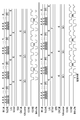
- FIG. 2 is a diagram showing delays of various signals.
- the DCLK, SA [1: 0], LAT, LOAD, STB, GSCLK and GScounter signals in the upper part of FIG. 2 are examples of control signals, and when conversion by the serializer 23 and the deserializer 31 is not performed, It is a waveform input to the drive IC 32.
- the signals of COM1, COM2 and DO1-256 in the upper part of FIG. 2 are examples of drive signals input to the drive IC 32.
- a delay of several ⁇ [sec] occurs.
- the delayed control signal input to the drive IC 32 is shown at the bottom of FIG. The delay time is between the two broken lines in FIG.
- the control signal and the drive signal need to be input to the drive IC 32 in a state where the timing is synchronized. Therefore, the control signal is converted by the serializer 23 and the deserializer 31, and when a delay occurs, it is necessary to delay the drive signal at the same time as the delay time of the control signal in order to synchronize the timing. Further, when the drive signal is delayed in order to synchronize the control signal and the drive signal, if the delay time is taken longer than necessary, the drive frequency is lowered by that amount. Therefore, by delaying the drive signal by the time for converting the control signal by the serializer 23 and the deserializer 31, it is possible to prevent the drive frequency from dropping. Specifically, as shown in the lower part of FIG. 2, the signals of COM1, COM2 and DO1-256 are delayed by the FPGA 21 by the time corresponding to the delay time of the control signal and input to the drive IC.
- the delay time of the control signal generated by the conversion in the serializer 23 and the deserializer 31 changes depending on the individual difference between the serializer 23 and the deserializer 31, the length of the FPC 4, the usage environment, the usage time, and the like. Therefore, in order to make the delay time of the drive signal the same as the delay time of the control signal, the reference signal 26 shown in FIG. 1 is used.
- the reference signal 26 is output from the FPGA 21 together with the control signal in a parallel signal system, and is input to the serializer 23.
- the reference signal 26 is serially converted together with the control signal in the serializer 23, and is input to the deserializer 31 via the FPC 4.
- the reference signal 26 is parallel-converted and output together with the control signal in the deserializer 31.
- the reference signal 26 output from the deserializer 31 is input to the FPGA 21 via the FPC 4. Therefore, the reference signal 26 has a delay in conversion by the serializer 23 and the deserializer 31, similar to the control signal.
- the delay time of the control signal and the delay time of the reference signal 26 are equivalent.
- the FPGA 21 determines the delay time of the drive signal based on the delay time of the reference signal 26, and outputs the delayed signal to the drive signal generation circuit 24.
- the FPGA 21 functions as a delay means and a determination means. The timing is synchronized by inputting the control signal delayed by the conversion in the serializer 23 and the deserializer 31 and the drive signal set to be delayed by the FPGA 21 to the drive IC 32.
- the inkjet recording device 1 of the present embodiment is connected to the drive board 2 that outputs a control signal and a drive signal for ejecting ink from a plurality of nozzles, respectively, via a cable 4.
- An inkjet recording device 1 including an inkjet head 3 that ejects ink from a nozzle based on a control signal output from the drive board 2 and a drive signal, the drive board 2 generates a control signal and a drive signal.
- the inkjet head 3 includes a generation means (FPGA 21, drive signal generation circuit 24), and the inkjet head 3 includes a conversion means (deserializer 31) that converts a control signal received via the cable 4 from a serial signal to a parallel signal, and the cable 4.
- a drive means for driving an actuator for ejecting ink by inputting a drive signal received via A delay means (FPGA21) for delaying only the delay time is provided. Therefore, the control signal in the form of a serial signal transmitted from the drive board 2 to the inkjet head 3 and the drive signal can be suitably synchronized.
- FIG. 3 is a diagram showing an inkjet recording device 1 according to a modification 1. Hereinafter, the difference from FIG. 1 showing the inkjet recording apparatus 1 of the above embodiment will be mainly described.
- the drive board 2 has two serializers 23a and 23b. Further, the inkjet head 3 has two deserializers 31a and 31b corresponding to the serializers 23a and 23b.
- the serializer 23 and the deserializer 31 are configured in twos each, but the configuration is not limited to this. It may be configured to have three or more each.
- the serializer 23a serially converts a part of the control signal of the parallel signal system output from the FPGA 21 and the reference signal 26a.
- the control signal and the reference signal 26a serially converted by the serializer 23a are input to the deserializer 31a via the FPC 4.
- the deserializer 31a converts the input serially converted control signal and reference signal 26a in parallel.
- the control signal and the reference signal 26a are delayed in the delay time a by the conversion in the serializer 23a and the deserializer 31a.
- the control signal converted in parallel is input to the drive IC 32.
- the parallel-converted reference signal 26a is input to the FPGA 21 via the FPC 4.
- the serializer 23b serially converts a part of the control signal of the parallel signal system output from the FPGA 21 and the reference signal 26b.
- the control signal and the reference signal 26b serially converted by the serializer 23b are input to the deserializer 31b via the FPC 4.
- the deserializer 31b parallel-converts the input serially converted control signal and reference signal 26b.
- the control signal and the reference signal 26b are delayed by the delay time b due to the conversion in the serializer 23b and the deserializer 31b.
- the control signal converted in parallel is input to the drive IC 32.
- the parallel-converted reference signal 26b is input to the FPGA 21 via the FPC 4.
- the FPGA 21 compares the delay time a indicated by the input reference signal 26a with the delay time b indicated by the reference signal 26b, and determines the delay time of the drive signal based on the longer time.
- the control signal in the form of a serial signal transmitted from the drive board to the inkjet head is used.
- the drive signal can be suitably synchronized.
- FIG. 4 is a diagram showing an inkjet recording device 1 according to a modification 2.
- FIG. 4 shows the difference from FIG. 1 showing the inkjet recording apparatus 1 of the above embodiment will be mainly described.
- the drive board 2 has two serializers 23a and 23b and two drive signal generation circuits 24a and 24b.
- the inkjet head 3a is connected to the drive substrate 2 via the FPC 4a
- the inkjet head 3b is connected to the drive substrate 2 via the FPC 4b.
- the serializer 23a and the drive signal generation circuit 24a correspond to the inkjet head 3a
- the serializer 23b and the drive signal generation circuit 24b correspond to the inkjet head 3b.
- the number of inkjet heads connected to the drive substrate 2 is two, but the number is not limited to this. Three or more inkjet heads may be connected.
- the inkjet head 3a includes a deserializer 31a, a drive IC 32a, an actuator 33a, a nozzle row 34a, and the like.
- the inkjet head 3b includes a deserializer 31b, a drive IC 32b, an actuator 33b, a nozzle row 34b, and the like.
- the serializer 23a serially converts a part of the control signal of the parallel signal system output from the FPGA 21 and the reference signal 26a.
- the control signal and the reference signal 26a serially converted by the serializer 23a are input to the deserializer 31a via the FPC 4a.
- the deserializer 31a converts the input serially converted control signal and reference signal 26a in parallel.
- the control signal and the reference signal 26a are delayed in the delay time a by the conversion in the serializer 23a and the deserializer 31a.
- the control signal converted in parallel is input to the drive IC 32a.
- the parallel-converted reference signal 26a is input to the FPGA 21 via the FPC4a.
- the serializer 23b serially converts a part of the control signal of the parallel signal system output from the FPGA 21 and the reference signal 26b.
- the control signal and the reference signal 26b serially converted by the serializer 23b are input to the deserializer 31b via the FPC 4b.
- the deserializer 31b parallel-converts the input serially converted control signal and reference signal 26b.
- the control signal and the reference signal 26b are delayed by the delay time b due to the conversion in the serializer 23b and the deserializer 31b.
- the parallel-converted control signal is input to the drive IC 32b.
- the parallel-converted reference signal 26b is input to the FPGA 21 via the FPC4b.
- the delay time of the drive signal for driving the actuators 33a and 33b needs to be unified among the inkjet heads driven by the same drive substrate 2. Therefore, the FPGA 21 compares the delay time a indicated by the input reference signal 26a with the delay time b indicated by the reference signal 26b, and determines the delay time of the drive signal based on the longer time.
- control signal in the form of a serial signal transmitted from the drive board to the inkjet head and the drive signal are suitably synchronized. be able to.
- the determination of the delay time of the drive signal in the above-described embodiment and modification may be performed after the power is turned on to the inkjet recording device 1, or may be performed periodically.
- the delay time of the drive signal is determined based on the delay time of the reference signal 26, but the present invention is not limited to this.
- Printing may be performed by the inkjet recording apparatus 1, the amount of deviation in printing timing may be calculated from the read data obtained by reading the printing result, and the delay time of the drive signal required for timing synchronization with the control signal may be determined from the amount of deviation. ..
- the FPGA 21 determines the delay time of the drive signal based on the delay time of the reference signal 26 as the determination means, but the present invention is not limited to this.
- An external device such as a computer connected via the input / output interface 22 may determine the delay time of the drive signal.
- the delay time information of the reference signal 26 is output to an external device via the FPGA 21 and the input / output interface 22, and is used to determine the delay time of the drive signal. Therefore, in this case, the external device is also included in the inkjet recording device 1. Further, the delay time may be a predetermined fixed value.
- the FPGA 21 performs arithmetic processing, performs various control processing related to the image recording operation in the inkjet recording device 1, and also performs various control processing related to the image recording operation in the inkjet recording device 1, and the delay time of the drive signal is based on the delay time of the reference signal 26.
- It has a CPU (Central Processing Unit) together with the FPGA, and the FPGA and the CPU perform arithmetic processing, perform various control processing related to the image recording operation in the inkjet recording device 1, and drive signals based on the delay time of the reference signal 26.
- the delay time of may be determined.
- the CPU may be configured to function as a delay means by executing a program.
- the present invention can be used for an inkjet recording device and a program for controlling an inkjet recording device.
- Inkjet recording device 2 Drive board 21 FPGA (generation means, delay means) 22 Input / output interface 23, 23a, 23b Serializer 24, 24a, 24b Drive signal generation circuit (generation means) 25 Unit control unit 26, 26a, 26b Reference signal 3, 3a, 3b Inkjet head 31, 31a, 31b Deserializer (conversion means) 32a, 32b drive IC (drive means) 33, 33a, 33b Actuator 34, 34a, 34b Nozzle row 4, 4a, 4b FPC (cable)
Landscapes
- Particle Formation And Scattering Control In Inkjet Printers (AREA)
- Ink Jet (AREA)
Priority Applications (2)
| Application Number | Priority Date | Filing Date | Title |
|---|---|---|---|
| JP2022531206A JP7468647B2 (ja) | 2020-06-18 | 2020-06-18 | インクジェット記録装置及びプログラム |
| PCT/JP2020/023996 WO2021255904A1 (ja) | 2020-06-18 | 2020-06-18 | インクジェット記録装置及びプログラム |
Applications Claiming Priority (1)
| Application Number | Priority Date | Filing Date | Title |
|---|---|---|---|
| PCT/JP2020/023996 WO2021255904A1 (ja) | 2020-06-18 | 2020-06-18 | インクジェット記録装置及びプログラム |
Publications (1)
| Publication Number | Publication Date |
|---|---|
| WO2021255904A1 true WO2021255904A1 (ja) | 2021-12-23 |
Family
ID=79267682
Family Applications (1)
| Application Number | Title | Priority Date | Filing Date |
|---|---|---|---|
| PCT/JP2020/023996 Ceased WO2021255904A1 (ja) | 2020-06-18 | 2020-06-18 | インクジェット記録装置及びプログラム |
Country Status (2)
| Country | Link |
|---|---|
| JP (1) | JP7468647B2 (https=) |
| WO (1) | WO2021255904A1 (https=) |
Citations (5)
| Publication number | Priority date | Publication date | Assignee | Title |
|---|---|---|---|---|
| JPH10138473A (ja) * | 1996-11-07 | 1998-05-26 | Seiko Epson Corp | プリンタヘッドの駆動回路 |
| JPH11138798A (ja) * | 1997-09-08 | 1999-05-25 | Konica Corp | インクジェットプリンタ |
| JP2000158643A (ja) * | 1998-09-25 | 2000-06-13 | Brother Ind Ltd | 記録装置 |
| US20070070104A1 (en) * | 2005-09-26 | 2007-03-29 | Samsung Electronics Co., Ltd. | Head driving device, inkjet printer comprising the same, and data processing method thereof |
| JP2009045761A (ja) * | 2007-08-14 | 2009-03-05 | Fuji Xerox Co Ltd | 液滴吐出装置 |
-
2020
- 2020-06-18 WO PCT/JP2020/023996 patent/WO2021255904A1/ja not_active Ceased
- 2020-06-18 JP JP2022531206A patent/JP7468647B2/ja active Active
Patent Citations (5)
| Publication number | Priority date | Publication date | Assignee | Title |
|---|---|---|---|---|
| JPH10138473A (ja) * | 1996-11-07 | 1998-05-26 | Seiko Epson Corp | プリンタヘッドの駆動回路 |
| JPH11138798A (ja) * | 1997-09-08 | 1999-05-25 | Konica Corp | インクジェットプリンタ |
| JP2000158643A (ja) * | 1998-09-25 | 2000-06-13 | Brother Ind Ltd | 記録装置 |
| US20070070104A1 (en) * | 2005-09-26 | 2007-03-29 | Samsung Electronics Co., Ltd. | Head driving device, inkjet printer comprising the same, and data processing method thereof |
| JP2009045761A (ja) * | 2007-08-14 | 2009-03-05 | Fuji Xerox Co Ltd | 液滴吐出装置 |
Also Published As
| Publication number | Publication date |
|---|---|
| JPWO2021255904A1 (https=) | 2021-12-23 |
| JP7468647B2 (ja) | 2024-04-16 |
Similar Documents
| Publication | Publication Date | Title |
|---|---|---|
| EP2072260B1 (en) | Head element substrate, recording head, and recording apparatus | |
| JP6488663B2 (ja) | 液体吐出装置および液体吐出モジュール | |
| US20180272705A1 (en) | Driving waveform generating device, liquid discharge head, inkjet recording apparatus, and driving waveform generating method | |
| US10265955B2 (en) | Liquid discharge apparatus | |
| US8857934B2 (en) | Print element substrate, printhead, and printing apparatus | |
| US7438372B2 (en) | Driver device for recording head | |
| JP6554965B2 (ja) | 液体吐出装置、および液体吐出装置の制御方法 | |
| JP7468647B2 (ja) | インクジェット記録装置及びプログラム | |
| CN113442580B (zh) | 打印头、液体喷出装置以及电容性负载驱动用集成电路装置 | |
| JP7683683B2 (ja) | 液体吐出装置、プログラム及び液体吐出ヘッド | |
| US7296865B2 (en) | Liquid ejection method, computer-readable medium, liquid ejection apparatus, and liquid ejection system | |
| JP6717367B2 (ja) | 液体吐出装置 | |
| JP5803531B2 (ja) | プリントヘッド制御回路、印刷装置、プリントヘッド制御方法、印刷物生産方法、プリントヘッド制御用信号生成送信回路およびプリントヘッドユニット | |
| JP6217819B2 (ja) | 印刷装置、およびラインヘッドユニット | |
| JP3753075B2 (ja) | インクジェット記録装置 | |
| JP2016150455A (ja) | 液体吐出装置 | |
| JP2008100483A (ja) | ヘッド基板、記録ヘッド、及び記録装置 | |
| JP4934997B2 (ja) | 記録装置 | |
| US12427766B2 (en) | Drive board, liquid jet head, and liquid jet recording device | |
| JP2016215524A (ja) | 液体吐出装置 | |
| JP7853077B2 (ja) | インクジェットヘッド及びインクジェット記録装置 | |
| JP6008029B2 (ja) | プリントヘッド制御回路、印刷装置、プリントヘッド制御方法、印刷物生産方法、プリントヘッド制御用信号生成送信回路およびプリントヘッドユニット | |
| JP7044155B2 (ja) | インクジェットヘッド、及び画像形成装置 | |
| EP3427954A1 (en) | Printing device, and method of controlling printing device | |
| JP2020196172A (ja) | 画像形成装置、及び画像形成装置の制御方法 |
Legal Events
| Date | Code | Title | Description |
|---|---|---|---|
| 121 | Ep: the epo has been informed by wipo that ep was designated in this application |
Ref document number: 20941491 Country of ref document: EP Kind code of ref document: A1 |
|
| ENP | Entry into the national phase |
Ref document number: 2022531206 Country of ref document: JP Kind code of ref document: A |
|
| NENP | Non-entry into the national phase |
Ref country code: DE |
|
| 122 | Ep: pct application non-entry in european phase |
Ref document number: 20941491 Country of ref document: EP Kind code of ref document: A1 |