WO2021251319A1 - 密封構造 - Google Patents
密封構造 Download PDFInfo
- Publication number
- WO2021251319A1 WO2021251319A1 PCT/JP2021/021503 JP2021021503W WO2021251319A1 WO 2021251319 A1 WO2021251319 A1 WO 2021251319A1 JP 2021021503 W JP2021021503 W JP 2021021503W WO 2021251319 A1 WO2021251319 A1 WO 2021251319A1
- Authority
- WO
- WIPO (PCT)
- Prior art keywords
- seal ring
- peripheral surface
- shaft
- protrusion
- inner peripheral
- Prior art date
- Legal status (The legal status is an assumption and is not a legal conclusion. Google has not performed a legal analysis and makes no representation as to the accuracy of the status listed.)
- Ceased
Links
Images





Classifications
-
- F—MECHANICAL ENGINEERING; LIGHTING; HEATING; WEAPONS; BLASTING
- F16—ENGINEERING ELEMENTS AND UNITS; GENERAL MEASURES FOR PRODUCING AND MAINTAINING EFFECTIVE FUNCTIONING OF MACHINES OR INSTALLATIONS; THERMAL INSULATION IN GENERAL
- F16J—PISTONS; CYLINDERS; SEALINGS
- F16J15/00—Sealings
- F16J15/16—Sealings between relatively-moving surfaces
- F16J15/18—Sealings between relatively-moving surfaces with stuffing-boxes for elastic or plastic packings
-
- F—MECHANICAL ENGINEERING; LIGHTING; HEATING; WEAPONS; BLASTING
- F16—ENGINEERING ELEMENTS AND UNITS; GENERAL MEASURES FOR PRODUCING AND MAINTAINING EFFECTIVE FUNCTIONING OF MACHINES OR INSTALLATIONS; THERMAL INSULATION IN GENERAL
- F16J—PISTONS; CYLINDERS; SEALINGS
- F16J15/00—Sealings
- F16J15/16—Sealings between relatively-moving surfaces
- F16J15/18—Sealings between relatively-moving surfaces with stuffing-boxes for elastic or plastic packings
- F16J15/181—Sealings between relatively-moving surfaces with stuffing-boxes for elastic or plastic packings for plastic packings
-
- F—MECHANICAL ENGINEERING; LIGHTING; HEATING; WEAPONS; BLASTING
- F16—ENGINEERING ELEMENTS AND UNITS; GENERAL MEASURES FOR PRODUCING AND MAINTAINING EFFECTIVE FUNCTIONING OF MACHINES OR INSTALLATIONS; THERMAL INSULATION IN GENERAL
- F16J—PISTONS; CYLINDERS; SEALINGS
- F16J15/00—Sealings
- F16J15/16—Sealings between relatively-moving surfaces
- F16J15/18—Sealings between relatively-moving surfaces with stuffing-boxes for elastic or plastic packings
- F16J15/188—Split assemblies
-
- F—MECHANICAL ENGINEERING; LIGHTING; HEATING; WEAPONS; BLASTING
- F16—ENGINEERING ELEMENTS AND UNITS; GENERAL MEASURES FOR PRODUCING AND MAINTAINING EFFECTIVE FUNCTIONING OF MACHINES OR INSTALLATIONS; THERMAL INSULATION IN GENERAL
- F16J—PISTONS; CYLINDERS; SEALINGS
- F16J15/00—Sealings
- F16J15/16—Sealings between relatively-moving surfaces
- F16J15/32—Sealings between relatively-moving surfaces with elastic sealings, e.g. O-rings
- F16J15/3268—Mounting of sealing rings
- F16J15/3272—Mounting of sealing rings the rings having a break or opening, e.g. to enable mounting on a shaft otherwise than from a shaft end
Definitions
- the present invention relates to a sealing structure for sealing a gap between a shaft and a shaft hole into which the shaft is inserted, and particularly to a structure of a seal ring and a groove of the shaft.
- sealing devices In automatic transmissions (ATs) and continuously variable transmissions (CVTs) of vehicles, sealing devices have been conventionally used in order to prevent leakage of hydraulic oil used for hydraulic control.
- a sealing ring which is used to seal the gap between the shaft and the shaft hole into which the shaft is inserted.
- the seal ring is attached to a groove formed on the outer peripheral surface of the shaft, and by contacting the side surface of the groove with the inner peripheral surface of the shaft hole, the space between the shaft and the shaft hole is sealed.
- the hydraulic pressure of the hydraulic oil is maintained between the shaft and the shaft hole.
- the seal ring is not endless, but is divided, and a joint is provided at this divided part.
- the abutment portions are formed so as to be in contact with each other in the use state so that there is no gap in the abutment portion, and the seal ring has a structure that seals the gap even in the abutment portion in the use state. (For example, see Patent Document 1).
- Some seal rings are used in the reducer of the motor mechanism of electric vehicles (EV) and hybrid electric vehicles (HEV), and the seal ring is intended to prevent leakage of cooling oil in the reducer.
- the hydraulic pressure due to the cooling oil in such a speed reducer is minute or no pressure, and the hydraulic pressure applied to the seal ring is lower than the hydraulic pressure applied to the seal ring used for sealing the hydraulic oil having a high pressure in AT or the like. Become.
- Some seal rings used in a low pressure environment such as a speed reducer are formed by injection molding using a resin material.
- a seal ring is formed in a state where the abutment portion is widened at the time of injection molding, and then the seal ring is corrected (reduced in diameter) so as to have a desired diameter.
- a hard resin such as PEEK (polyetheretherketone) or PPS (polyphenylene sulfide) is used as the resin material, it is difficult to straighten to the desired diameter. Is.
- the roundness of the seal ring in use is insufficient, and a gap is formed between the inner peripheral surface of the shaft hole and the outer peripheral surface of the seal ring.
- the hydraulic pressure of high-pressure hydraulic oil is applied, so that the seal ring is pressed against the inner peripheral surface of the shaft hole, and the gap on the outer peripheral side due to insufficient roundness of the seal ring disappears. ..
- the present invention has been made in view of the above problems, and an object of the present invention is to provide a sealing structure capable of suppressing the generation of a gap between the inner peripheral surface of the shaft hole and the outer peripheral surface of the seal ring. There is something in it.
- the sealing structure according to the present invention is a sealing structure for sealing an annular gap between the shaft and the shaft hole into which the shaft is inserted, and is a groove of the shaft.
- the seal ring is provided with an annular seal ring around the axis and a locked portion formed on the bottom surface of the groove of the shaft, and the seal ring has a locking portion formed on the inner peripheral surface.
- the locking portion and the locked portion are formed so as to be lockable to each other, and the seal ring is formed so as to be pushed toward the outer peripheral side when the locking portion and the locked portion are locked to each other. It is a feature.
- the locking portion has at least one protrusion protruding toward the inner peripheral side, and the locked portion is recessed toward the same number of inner peripheral sides as the protrusion. It has a groove, and the groove is formed so as to accommodate the protrusion.
- the diameter of the portion most protruding toward the inner peripheral side of the protrusion is smaller than the diameter of the outer peripheral surface of the shaft.
- the radial thickness of the seal ring at the portion most protruding toward the inner peripheral side of the protrusion is between the outer peripheral surface of the shaft and the inner peripheral surface of the shaft hole. Greater than the radial length of.
- the sealing structure according to the present invention it is possible to suppress the generation of a gap between the inner peripheral surface of the shaft hole and the outer peripheral surface of the seal ring.
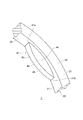
- FIG. 3 is a partially enlarged perspective view showing the vicinity of the protrusion of the seal ring shown in FIG. 3 in an enlarged manner.
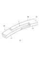
- FIG. 3 is a partially enlarged perspective view showing the vicinity of the joint portion of the seal ring shown in FIG. 3 in an enlarged manner.
- the sealing structure 1 is a sealing device for sealing an annular gap between a shaft and a shaft hole into which the shaft is inserted.
- the sealing structure 1 is used in a vehicle or a general-purpose machine to seal between a shaft that rotates relative to each other and a shaft hole formed in a housing or the like into which the shaft is inserted.
- the sealed structure 1 is used, for example, in a speed reducer of an EV or HEV motor mechanism, or in an AT or CTV.
- the sealed structure 1 is suitably used for a speed reducer or the like of a motor mechanism having a low internal hydraulic pressure.
- the target (mounting target) to which the sealing structure 1 according to the embodiment of the present invention is applied is not limited to the above.
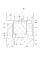
- FIG. 1 is a cross-sectional view taken along the cross section orthogonal to the axis x, showing a schematic configuration of the sealed structure 1 according to the embodiment of the present invention.
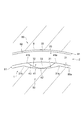
- FIG. 2 is a cross-sectional view taken along the axis x showing a schematic configuration of the sealed structure 1.
- FIG. 3 is a side view of one side showing the schematic configuration of the seal ring 2
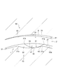
- FIG. 4 is a partially enlarged perspective view showing the schematic configuration of the seal ring 2, and the vicinity of the protrusion 41 of the seal ring 2 is enlarged. Is shown.
- FIG. 5 is a partially enlarged perspective view showing a schematic configuration of the seal ring 2, and shows an enlarged view of the vicinity of the abutment portion 5 of the seal ring 2.
- FIG. 5 is a partially enlarged perspective view showing a schematic configuration of the seal ring 2, and shows an enlarged view of the vicinity of the abutment portion 5 of the seal ring 2.
- FIG. 5 is a partially enlarged perspective view showing
- FIGS. 1 to 5 are cross-sectional views of a groove 51 of the shaft 50 in which the locked portion 3 of the sealed structure 1 is formed and a shaft hole 61 into which the shaft 50 is inserted.
- the shaft hole 61 is, for example, the housing 60 of the speed reducer R.
- the seal ring 2 is shown in a free state to which no external force is applied.
- the sealing structure 1 has an annular seal ring 2 around the axis x, which is attached to the groove 51 of the shaft 50, and a locked portion formed on the bottom surface 52 of the groove 51 of the shaft 50. It is equipped with 3.
- the seal ring 2 has a locking portion 4 formed on the inner peripheral surface 21.
- the locking portion 4 and the locked portion 3 are formed so as to be able to be locked to each other, and the seal ring 2 is formed so as to be pushed toward the outer peripheral side when the locking portion 4 and the locked portion 3 are locked to each other.
- the sealed structure 1 will be specifically described.
- the seal ring 2 is shown in a mounted state in a natural state when the shaft 50 is not rotating. Further, in FIGS. 1 and 2, the locked portion 4 and the locked portion 3 are shown in a state where they are not locked to each other. In the sealed structure 1, the locking portion 4 is housed in the locked portion 3. Further, in the mounted state, as will be described later, a gap S may be formed in a part between the seal ring 2 and the shaft hole 61.
- the seal ring 2 has a main body portion 20.
- the main body portion 20 is a portion extending in an annular shape around the axis x, and the shape of the cross section on the surface along the axis x is rectangular or substantially rectangular, and the inner peripheral surface 21 which is a surface facing the inner peripheral side and the outer peripheral side. It has an outer peripheral surface 22 which is a facing surface, and side surfaces 23 and 24 which face each other.
- the inner peripheral surface 21 and the outer peripheral surface 22 face each other, and the side surfaces 23 and 24 are surfaces facing the axis x direction.
- the inner peripheral surface 21 is, for example, a cylindrical surface or a substantially cylindrical surface centered or substantially centered on the axis x
- the outer peripheral surface 22 is, for example, a cylindrical surface or a substantially cylindrical surface centered or substantially centered on the axis x. ..
- the side surfaces 23 and 24 extend between the inner peripheral surface 21 and the outer peripheral surface 22.
- the side surfaces 23 and 24 are, for example, a plane orthogonal to or substantially orthogonal to the axis x or an annular surface extending in a substantially plane.
- the seal ring 2 is not endless, but is divided at one point in the circumferential direction, and as shown in FIGS. 3 and 5, a joint portion 5 is provided at this divided portion.
- the joint portion 5 has a known structure capable of maintaining stable sealing performance even if the peripheral length of the sealing ring 2 changes due to thermal expansion or contraction of the sealing ring 2.
- a so-called special step cut structure or a straight cut which is cut in a stepped shape when viewed from either the outer peripheral surface 22 side or the both side surfaces 23 and 24 sides, or a straight cut
- the seal ring 2 is provided with a locking portion 4, and the locking portion 4 has at least one protrusion 41 protruding toward the inner peripheral side as shown in FIGS. 1 to 4. is doing.
- the seal ring 2 has two protrusions 41.
- the diameter of the top portion 42 which is the most protruding portion on the inner peripheral side of each protrusion 41, is smaller than the diameter of the outer peripheral surface 50a of the shaft 50.
- the radial thickness of the seal ring 2 at the top 42 of the protrusion 41 is larger than the radial length (width) between the outer peripheral surface 50a of the shaft 50 and the inner peripheral surface 62 of the shaft hole 61. ing.
- the protrusion 41 is a portion extending along the inner peripheral surface 21 in a part of the extending direction (circumferential direction) of the inner peripheral surface 21 of the main body portion 20, and protrudes from the inner peripheral surface 21. It is a part.
- the protrusion 41 has a locking surface 43 which is a surface facing the inner peripheral side.
- the locking surface 43 is, for example, a curved surface protruding toward the inner peripheral surface, and the radial height from the inner peripheral surface 21 increases toward the top 42 from each of the circumferential ends 41a and 41b of the protrusion 41. It is a gentle curved surface.
- the protrusion 41 has a width in the axis x direction smaller than the width in the axis x direction of the main body 20, and is a side surface of the protrusion 41 facing the axis x direction.
- the 44 and 45 are not flush with the side surfaces 23 and 24 of the main body 20, and a step is formed between the side surfaces 44 and 45 and the side surfaces 23 and 24, respectively.
- the side surfaces 44 and 45 of the protrusion 41 may be flush with the side surfaces 23 and 24 of the main body 20, respectively, and the side surface 44 of the protrusion 41, the side surface 23 of the main body 20 and the side surface 45 of the protrusion 41 may be flush with each other. And one of the side surfaces 24 of the main body 20 may be flush with each other.
- the two protrusions 41 are provided at symmetrical positions on the seal ring 2, for example, and specifically, as shown in FIG. 3, the same from the abutment portion 5 on the inner peripheral surface 21 of the main body portion 20. It is provided at a distance or a position at substantially the same distance, or at the same angle position or a position at substantially the same angle.
- the positions where the protrusions 41 are provided in the seal ring 2 are the outer peripheral surface 22 of the seal ring 2 and the inner peripheral surface of the shaft hole 61, which are formed based on the lack of roundness of the seal ring 2 in the mounted state. An effective position is preferred for eliminating or reducing the gap S between 62.
- the seal ring 2 is formed by injection molding from a resin material such as polyetheretherketone (PEEK), polyphenylene sulfide (PPS), polyetheretherketone (PEEK), polyphenylene sulfide (PPS), or polytetrafluoroethylene (PTFE). ing.
- a resin material such as polyetheretherketone (PEEK), polyphenylene sulfide (PPS), polyetheretherketone (PEEK), polyphenylene sulfide (PPS), or polytetrafluoroethylene (PTFE).
- the seal ring 2 is formed so as to have a desired roundness and the outer peripheral surface 22 of the seal ring 2 is in contact with the inner peripheral surface 62 of the shaft hole 61 over the entire circumferential direction in the mounted state.
- the body is reduced in diameter and corrected to form the seal ring 2.
- the locked portion 3 is provided on the bottom surface 52 of the groove 51 of the shaft 50 in which the seal ring 2 is accommodated and mounted, and as shown in FIGS. 1, 2, and 6, the locked portion 3 is provided.
- Reference numeral 3 has the same number of locking grooves 31 as the protrusions 41, which are recessed on the inner peripheral side. That is, in the present embodiment, two locking grooves 31 are formed on the bottom surface 52 of the groove 51.
- the locking groove 31 is formed so as to accommodate the protrusion 41. That is, as shown in FIG. 1, the locking groove 31 is formed so that the two protrusions 41 are respectively accommodated in the corresponding locking grooves 31 in the mounted state.
- the locking groove 31 is provided at the position of the bottom surface 52 of the groove 51 so as to have the same positional relationship as the positional relationship of the protrusion 41 with respect to the axis x, and the angle spacing around the axis x of the protrusion 41 , The angular spacing around the axis x of the locking groove 31 is the same or substantially the same.
- the locking groove 31 extends along the bottom surface 52 in a part of the extending direction (circumferential direction) of the bottom surface 52 of the groove 51 of the shaft 50, and the locking groove 31 extends on the outer peripheral side. It has a locked surface 32 which is a surface facing the surface.
- the locked surface 32 is, for example, a curved surface recessed toward the inner peripheral side, and is a gentle curved surface whose radial depth from the bottom surface 52 becomes deeper toward the bottom portion 33 from each of the circumferential end portions 31a and 31b. ..
- the locked surface 32 of the locking groove 31 is a gentler surface than the locking surface 43 of the protrusion 41. For example, the curvature of the locked surface 32 is locked.
- the locked surface 32 extends longer in the circumferential direction than the locking surface 43.
- the locked surface 32 may not be a gentler surface than the locking surface 43, and the locked surface 32 may not extend longer in the circumferential direction than the locking surface 43.
- the locking groove 31 can accommodate the protrusion 41, and the width of the locking groove 31 in the axis x direction is set so as to accommodate the protrusion 41.
- the width of the locking groove 31 in the axis x direction is larger than the width of the protrusion 41 in the axis x direction.
- the width of the locking groove 31 in the axis x direction is the same as the width of the bottom surface 52 of the groove 51 in the axis x direction, and faces the locking groove 31 in the axis x direction.
- the side surfaces 34 and 35 which are surfaces, are flush with the side surfaces 53 and 54 of the groove 51, respectively.
- the width of the locking groove 31 in the axis x direction may be smaller than the width of the bottom surface 52 of the groove 51 in the axis x direction, and between the side surfaces 34 and 35 and the side surfaces 53 and 54, respectively.
- a step may be formed, and any one of the side surface 34 of the locking groove 31, the side surface 53 of the groove 51, the side surface 35 of the locking groove 31, and the side surface 54 of the groove 51 is flush with each other. , The other may form a step.
- the diameter of the top portion 42 of the protrusion 41 is smaller than the diameter of the outer peripheral surface 50a of the shaft 50. Further, as shown in FIG. 1, in a state where the top portion 42 of the protrusion 41 and the bottom portion 33 of the locking groove 31 overlap each other in the radial direction, a gap is formed between the top portion 42 and the bottom portion 33. Therefore, in the mounted state, the seal ring 2 can rotate and move around the axis x. If the seal ring 2 can rotate and move around the axis x in the mounted state, the top 42 and the bottom 33 are in a state where the top 42 of the protrusion 41 and the bottom 33 of the locking groove 31 overlap in the radial direction.
- the radial thickness of the seal ring 2 at the top 42 of the protrusion 41 is the radial length (width) between the outer peripheral surface 50a of the shaft 50 and the inner peripheral surface 62 of the shaft hole 61. ), And the seal ring 2 cannot rotate around the axis x until the protrusion 41 goes out of the locking groove 31. That is, when the seal ring 2 rotates around the axis x from the position where the top 42 of the protrusion 41 and the bottom 33 of the locking groove 31 overlap in the radial direction, the locking surface 43 of the protrusion 41 engages at the position where the protrusion 41 overlaps in the radial direction.
- the protrusion 41 and the locking groove 31 are locked to each other by contacting the locked surface 32 of the stop groove 31 and the outer peripheral surface 22 of the seal ring 2 in contact with the inner peripheral surface 62 of the shaft hole 61.
- the seal ring 2 cannot be rotated any further.
- the seal ring 2 is formed by injection molding from a resin material and then performing a straightening treatment. Even with this straightening treatment, for example, the joint portion 5 and the portion in the vicinity thereof may not have a desired diameter, and the roundness of the outer peripheral surface 22 of the seal ring 2 may be insufficient. That is, in the above-mentioned mounting state, the entire peripheral surface 22 of the seal ring 2 does not come into contact with the inner peripheral surface 62 of the shaft hole 61, and a part of the outer peripheral surface 22, for example, the abutment portion 5 or its vicinity.
- the portion may not come into contact with the inner peripheral surface 62 of the shaft hole 61, and a gap S may be created in this portion between the outer peripheral surface 22 of the seal ring 2 and the inner peripheral surface 62 of the shaft hole 61 (see FIG. 2). ).
- the seal ring 2 lacks roundness, and the portion in the vicinity of the abutment portion 5 does not contact the inner peripheral surface 62 of the shaft hole 61, and in the mounted state, in this portion. It is assumed that a gap S is created between the outer peripheral surface 22 of the seal ring 2 and the inner peripheral surface 62 of the shaft hole 61.
- FIG. 7 is a partial cross-sectional view showing the vicinity of the protrusion 41 and the locking groove 31 of the sealed structure 1 in the mounted state shown in FIG. 1 in an enlarged manner.
- the top portion 42 and the bottom portion 33 are in a state where the top portion 42 of the protrusion 41 and the bottom portion 33 of the locking groove 31 overlap each other in the radial direction. There is a gap between them.
- the portion of the outer peripheral surface 22 of the seal ring 2 in the vicinity of the abutment portion 5 does not come into contact with the inner peripheral surface 62 of the shaft hole 61.
- a minute gap S is formed between the outer peripheral surface 22 and the inner peripheral surface 62 of the shaft hole 61.
- the protrusion 41 further climbs the locked surface 32, and the protrusion 41 moves toward the outer periphery along the curved surface of the locked surface 32. It will be pushed up further.
- the locking surface 43 of the protrusion 41 is the locked surface 32 of the locking groove 31.
- the outer peripheral surface 22 of the seal ring 2 contacts the inner peripheral surface 62 of the shaft hole 61, the protrusion 41 and the locking groove 31 are locked to each other, and the seal ring 2 is attached to the shaft 50. It becomes impossible to move relative to the circumferential direction. That is, the seal ring 2 rotates together with the shaft 50.
- the protrusion 41 rises from the bottom 33 to the position of the maximum height in the radial direction, and the protrusion 41 is pushed up to the outer peripheral side by the curved surface of the locked surface 32. There is. For this reason, a part of the outer peripheral surface 22 of the main body 20 of the seal ring 2 is pushed up to the outer peripheral side to the maximum, which causes the outer peripheral surface 22 and the shaft hole of the seal ring 2 to be generated in the mounted state.
- the minute gap S between the inner peripheral surface 62 of 61 is reduced to the maximum. In the example of FIG. 9, the minute gap S between the outer peripheral surface 22 of the seal ring 2 and the inner peripheral surface 62 of the shaft hole 61, which has been generated in the mounted state, has disappeared.
- the minute gap S between the outer peripheral surface 22 of the seal ring 2 and the inner peripheral surface 62 of the shaft hole 61 which is generated in the mounted state, causes oil leakage in the speed reducer and the inside of the speed reducer from the outside. Foreign matter is prevented from entering.
- the protrusion 41 moves relative to the inside of the locking groove 31 in the rotational direction due to a slight rotation of the shaft 50 in the use state of the speed reducer R, and the protrusion 41 is covered with the locking groove 31.
- a part of the main body 20 of the seal ring 2 is pushed up to the outer peripheral side by climbing the locking surface 32.
- the main body 20 of the seal ring 2 is deformed so that the outer peripheral surface 22 of the seal ring 2 is pressed against the inner peripheral surface 62 of the shaft hole 61 in the entire circumferential direction, and the seal ring is generated in the mounted state.
- the minute gap S between the outer peripheral surface 22 of 2 and the inner peripheral surface 62 of the shaft hole 61 disappears or decreases.
- the sealing structure 1 can exert the effect of removing the gap S even in a no-pressure or low-pressure environment as described above, and can exert it regardless of the magnitude of the hydraulic pressure applied to the sealing ring 2. Therefore, the sealing structure 1 can remove or reduce the gap S due to the lack of roundness of the sealing ring 2, regardless of the attachment target.
- the sealing structure 1 As described above, according to the sealing structure 1 according to the embodiment of the present invention, it is possible to suppress the generation of a gap between the inner peripheral surface 62 of the shaft hole 61 and the outer peripheral surface 22 of the seal ring 2.
- the protrusion 41 moves relative to the inside of the locking groove 31, and the protrusion 41 climbs the locked surface 32 of the locking groove 31 to correspond to the main body portion 20 of the seal ring 2.
- the portion is pushed up to the outer peripheral side, and the minute gap S between the outer peripheral surface 22 of the seal ring 2 and the inner peripheral surface 62 of the shaft hole 61 is removed or reduced. Therefore, the form such as the number, position, and shape of the protrusion 41 and the locking groove 31 depends on the state in which the gap S between the outer peripheral surface 22 of the seal ring 2 to be removed and the inner peripheral surface 62 of the shaft hole 61 is generated. Each is set.
- the portion and amount of the main body portion 20 pushed up, and the deformation form of the seal ring 2 at this time vary depending on the position of the protrusion 41. Therefore, the position where the protrusion 41 is provided on the inner peripheral surface 21 of the seal ring 2 and the number of protrusions 41 can be set according to the portion and amount of the main body 20 to be pushed up and the form of the seal ring 2 to be deformed. preferable. Further, the portion and amount of the main body portion 20 pushed up, and the form of deformation of the seal ring 2 at this time vary depending on the shape of the locking surface 43 of the protrusion 41 and the shape of the locked surface 32 of the locking groove 31. come.
- the shape of the locking surface 43 of the protrusion 41 and the shape of the locked surface 32 of the locking groove 31 are set according to the portion and amount of the main body 20 to be pushed up and the form of the seal ring 2 to be deformed. Is preferable.
- the seal ring 2 may be provided with three protrusions 41, and the bottom surface 52 of the groove 51 of the shaft 50 may be provided with three corresponding locking grooves 31. It may have been.
- the two protrusions 41 are provided at positions symmetrical with respect to the abutment portion 5, and one protrusion 41 is provided so as to face the abutment portion 5.
- the locking groove 31 is provided at a position corresponding to each of the protrusions 41.
- the seal ring 2 may be provided with two protrusions 41, and the bottom surface 52 of the groove 51 of the shaft 50 may be provided with two corresponding locking grooves 31. It may have been.
- the two protrusions 41 are provided at positions symmetrically or substantially symmetrical with respect to the abutment portion 5, and are provided in the vicinity of the abutment portion 5.
- the locking groove 31 is provided at a position corresponding to each of the protrusions 41.
- the protrusion 41 and the locking groove 31 are each provided at an angle position closer to 45 ° from the abutment portion 5 on the inner peripheral surface 21 of the main body portion 20.
- a gap S is likely to occur between the outer peripheral surface 22 of the seal ring 2 and the inner peripheral surface 62 of the shaft hole 61. Therefore, if the protrusion 41 and the locking groove 31 are provided in the vicinity of the abutment portion 5 and symmetrically with respect to the abutment portion 5, the gap S generated in the vicinity of the abutment portion 5 can be reduced or eliminated. The effect of suppressing the generation of a gap S between the outer peripheral surface 22 of the seal ring 2 and the inner peripheral surface 62 of the shaft hole 61 can be enhanced.
- the sealing structure 1 due to the lack of roundness of the sealing ring 2, there is a minute gap between the outer peripheral surface 22 of the sealing ring 2 and the inner peripheral surface 62 of the shaft hole 61 in the mounted state. Although it is assumed that S is generated, the sealing structure 1 is used so that the sealing structure 1 operates in the same manner as the above-mentioned operation of the sealing structure 1 even when the sealing ring 2 is formed to have a desired roundness. be able to.
- the sealing structure 1 acts as described above, and the gap S can be reduced or eliminated. Further, even when the inner peripheral surface 62 of the seal ring 2 and the shaft hole 61 is formed in a desired shape, the sealing structure 1 acts as described above to improve the sealing performance.
- the present invention is not limited to the sealed structure 1 according to the embodiment of the present invention, and all aspects included in the concept and claims of the present invention are included. include.
- each configuration may be selectively combined as appropriate so as to achieve at least a part of the above-mentioned problems and effects.
- the shape, material, arrangement, size, etc. of each component in the above embodiment can be appropriately changed depending on the specific usage mode of the present invention.
- the locking surface 43 of the protrusion 41 and the locked surface 32 of the locking groove 31 are not limited to a curved surface, but may be a flat surface, a combination of flat surfaces, a combination of curved surfaces and flat surfaces, and the like. Further, a plurality of grooves extending in the circumferential direction may be formed on the outer peripheral surface 22 of the seal ring 2 so as to exert a dynamic pressure effect.
Landscapes
- Engineering & Computer Science (AREA)
- General Engineering & Computer Science (AREA)
- Mechanical Engineering (AREA)
- Sealing Devices (AREA)
Priority Applications (5)
| Application Number | Priority Date | Filing Date | Title |
|---|---|---|---|
| US17/923,950 US20230272858A1 (en) | 2020-06-09 | 2021-06-07 | Sealing structure |
| EP21821229.8A EP4163522A4 (en) | 2020-06-09 | 2021-06-07 | Sealing structure |
| KR1020227039373A KR20220166345A (ko) | 2020-06-09 | 2021-06-07 | 밀봉 구조 |
| CN202180033905.7A CN115605694A (zh) | 2020-06-09 | 2021-06-07 | 密封构造 |
| JP2022530544A JP7375197B2 (ja) | 2020-06-09 | 2021-06-07 | 密封構造 |
Applications Claiming Priority (2)
| Application Number | Priority Date | Filing Date | Title |
|---|---|---|---|
| JP2020100488 | 2020-06-09 | ||
| JP2020-100488 | 2020-06-09 |
Publications (1)
| Publication Number | Publication Date |
|---|---|
| WO2021251319A1 true WO2021251319A1 (ja) | 2021-12-16 |
Family
ID=78846036
Family Applications (1)
| Application Number | Title | Priority Date | Filing Date |
|---|---|---|---|
| PCT/JP2021/021503 Ceased WO2021251319A1 (ja) | 2020-06-09 | 2021-06-07 | 密封構造 |
Country Status (6)
| Country | Link |
|---|---|
| US (1) | US20230272858A1 (https=) |
| EP (1) | EP4163522A4 (https=) |
| JP (1) | JP7375197B2 (https=) |
| KR (1) | KR20220166345A (https=) |
| CN (1) | CN115605694A (https=) |
| WO (1) | WO2021251319A1 (https=) |
Cited By (2)
| Publication number | Priority date | Publication date | Assignee | Title |
|---|---|---|---|---|
| WO2022270127A1 (ja) * | 2021-06-22 | 2022-12-29 | Nok株式会社 | シールリングおよびそれを含む密封構造体 |
| US12618473B2 (en) | 2021-06-22 | 2026-05-05 | Nok Corporation | Sealing ring and sealed structure including same |
Citations (6)
| Publication number | Priority date | Publication date | Assignee | Title |
|---|---|---|---|---|
| JP2007127272A (ja) * | 2005-10-03 | 2007-05-24 | Nok Corp | シールリング及びシール構造 |
| JP2007292296A (ja) * | 2006-03-30 | 2007-11-08 | Nok Corp | シールリングおよびシールリング製造方法 |
| JP2008157397A (ja) * | 2006-12-26 | 2008-07-10 | Ntn Corp | シールリング |
| JP2014020303A (ja) * | 2012-07-19 | 2014-02-03 | Nippon Soken Inc | 内燃機関用ピストンおよびピストンリング |
| JP2015218791A (ja) * | 2014-05-15 | 2015-12-07 | Nok株式会社 | シールリング |
| JP2016014481A (ja) | 2014-06-12 | 2016-01-28 | 三菱電線工業株式会社 | シールリング |
Family Cites Families (7)
| Publication number | Priority date | Publication date | Assignee | Title |
|---|---|---|---|---|
| JPS53109503U (https=) * | 1977-02-07 | 1978-09-01 | ||
| JP5055978B2 (ja) * | 2006-11-29 | 2012-10-24 | Nok株式会社 | シールリング及びシール構造 |
| IT1393329B1 (it) * | 2009-01-21 | 2012-04-20 | Brondolin S P A | Pistone e anello di tenuta per pressofusione |
| EP3201498B1 (de) * | 2014-08-08 | 2019-09-25 | Konzelmann GmbH | Hakenschloss für eine rechteckdichtung sowie eine ein derartiges hakenschloss aufweisende rechteckdichtung |
| EP3201499A1 (de) * | 2014-08-08 | 2017-08-09 | Konzelmann GmbH | Rechteckdichtung zur abdichtung einer durchführung, insbesondere für fluide |
| KR101983012B1 (ko) * | 2015-05-01 | 2019-05-29 | 생-고뱅 퍼포먼스 플라스틱스 엘+에스 게엠베하 | 밀봉링 |
| DE102018114701A1 (de) * | 2018-06-19 | 2019-12-19 | Konzelmann Gmbh | Hydrodynamisch wirksamer Dichtring und Drehdurchführung mit einem solchen Dichtring |
-
2021
- 2021-06-07 US US17/923,950 patent/US20230272858A1/en not_active Abandoned
- 2021-06-07 JP JP2022530544A patent/JP7375197B2/ja active Active
- 2021-06-07 WO PCT/JP2021/021503 patent/WO2021251319A1/ja not_active Ceased
- 2021-06-07 EP EP21821229.8A patent/EP4163522A4/en not_active Withdrawn
- 2021-06-07 KR KR1020227039373A patent/KR20220166345A/ko not_active Ceased
- 2021-06-07 CN CN202180033905.7A patent/CN115605694A/zh active Pending
Patent Citations (6)
| Publication number | Priority date | Publication date | Assignee | Title |
|---|---|---|---|---|
| JP2007127272A (ja) * | 2005-10-03 | 2007-05-24 | Nok Corp | シールリング及びシール構造 |
| JP2007292296A (ja) * | 2006-03-30 | 2007-11-08 | Nok Corp | シールリングおよびシールリング製造方法 |
| JP2008157397A (ja) * | 2006-12-26 | 2008-07-10 | Ntn Corp | シールリング |
| JP2014020303A (ja) * | 2012-07-19 | 2014-02-03 | Nippon Soken Inc | 内燃機関用ピストンおよびピストンリング |
| JP2015218791A (ja) * | 2014-05-15 | 2015-12-07 | Nok株式会社 | シールリング |
| JP2016014481A (ja) | 2014-06-12 | 2016-01-28 | 三菱電線工業株式会社 | シールリング |
Non-Patent Citations (1)
| Title |
|---|
| See also references of EP4163522A4 |
Cited By (3)
| Publication number | Priority date | Publication date | Assignee | Title |
|---|---|---|---|---|
| WO2022270127A1 (ja) * | 2021-06-22 | 2022-12-29 | Nok株式会社 | シールリングおよびそれを含む密封構造体 |
| JP7510572B2 (ja) | 2021-06-22 | 2024-07-03 | Nok株式会社 | シールリングおよびそれを含む密封構造体 |
| US12618473B2 (en) | 2021-06-22 | 2026-05-05 | Nok Corporation | Sealing ring and sealed structure including same |
Also Published As
| Publication number | Publication date |
|---|---|
| CN115605694A (zh) | 2023-01-13 |
| EP4163522A1 (en) | 2023-04-12 |
| KR20220166345A (ko) | 2022-12-16 |
| EP4163522A4 (en) | 2024-06-26 |
| US20230272858A1 (en) | 2023-08-31 |
| JPWO2021251319A1 (https=) | 2021-12-16 |
| JP7375197B2 (ja) | 2023-11-07 |
Similar Documents
| Publication | Publication Date | Title |
|---|---|---|
| JP6491374B2 (ja) | シールリング | |
| JP6615833B2 (ja) | シールリング | |
| JP6245406B2 (ja) | シールリング | |
| JP6314689B2 (ja) | 密封装置 | |
| KR102362482B1 (ko) | 실 링 | |
| WO2021251319A1 (ja) | 密封構造 | |
| CN114761714B (zh) | 密封装置 | |
| JP6394819B2 (ja) | 軸及び密封構造 | |
| JP6170271B2 (ja) | シールリング | |
| JP7510572B2 (ja) | シールリングおよびそれを含む密封構造体 | |
| JP6458905B2 (ja) | シールリング | |
| US12618473B2 (en) | Sealing ring and sealed structure including same | |
| JP6803965B2 (ja) | シールリング | |
| JP2017101736A (ja) | シールリング |
Legal Events
| Date | Code | Title | Description |
|---|---|---|---|
| 121 | Ep: the epo has been informed by wipo that ep was designated in this application |
Ref document number: 21821229 Country of ref document: EP Kind code of ref document: A1 |
|
| ENP | Entry into the national phase |
Ref document number: 20227039373 Country of ref document: KR Kind code of ref document: A |
|
| ENP | Entry into the national phase |
Ref document number: 2022530544 Country of ref document: JP Kind code of ref document: A |
|
| NENP | Non-entry into the national phase |
Ref country code: DE |
|
| ENP | Entry into the national phase |
Ref document number: 2021821229 Country of ref document: EP Effective date: 20230109 |
|
| WWW | Wipo information: withdrawn in national office |
Ref document number: 2021821229 Country of ref document: EP |
|
| WWR | Wipo information: refused in national office |
Ref document number: 1020227039373 Country of ref document: KR |