WO2021246214A1 - 流体制御装置 - Google Patents
流体制御装置 Download PDFInfo
- Publication number
- WO2021246214A1 WO2021246214A1 PCT/JP2021/019530 JP2021019530W WO2021246214A1 WO 2021246214 A1 WO2021246214 A1 WO 2021246214A1 JP 2021019530 W JP2021019530 W JP 2021019530W WO 2021246214 A1 WO2021246214 A1 WO 2021246214A1
- Authority
- WO
- WIPO (PCT)
- Prior art keywords
- spool
- housing
- land portion
- chamber
- oil
- Prior art date
- Legal status (The legal status is an assumption and is not a legal conclusion. Google has not performed a legal analysis and makes no representation as to the accuracy of the status listed.)
- Ceased
Links
Images





Classifications
-
- F—MECHANICAL ENGINEERING; LIGHTING; HEATING; WEAPONS; BLASTING
- F16—ENGINEERING ELEMENTS AND UNITS; GENERAL MEASURES FOR PRODUCING AND MAINTAINING EFFECTIVE FUNCTIONING OF MACHINES OR INSTALLATIONS; THERMAL INSULATION IN GENERAL
- F16K—VALVES; TAPS; COCKS; ACTUATING-FLOATS; DEVICES FOR VENTING OR AERATING
- F16K11/00—Multiple-way valves, e.g. mixing valves; Pipe fittings incorporating such valves
- F16K11/02—Multiple-way valves, e.g. mixing valves; Pipe fittings incorporating such valves with all movable sealing faces moving as one unit
- F16K11/06—Multiple-way valves, e.g. mixing valves; Pipe fittings incorporating such valves with all movable sealing faces moving as one unit comprising only sliding valves, i.e. sliding closure elements
- F16K11/065—Multiple-way valves, e.g. mixing valves; Pipe fittings incorporating such valves with all movable sealing faces moving as one unit comprising only sliding valves, i.e. sliding closure elements with linearly sliding closure members
- F16K11/07—Multiple-way valves, e.g. mixing valves; Pipe fittings incorporating such valves with all movable sealing faces moving as one unit comprising only sliding valves, i.e. sliding closure elements with linearly sliding closure members with cylindrical slides
- F16K11/0716—Multiple-way valves, e.g. mixing valves; Pipe fittings incorporating such valves with all movable sealing faces moving as one unit comprising only sliding valves, i.e. sliding closure elements with linearly sliding closure members with cylindrical slides with fluid passages through the valve member
-
- F—MECHANICAL ENGINEERING; LIGHTING; HEATING; WEAPONS; BLASTING
- F16—ENGINEERING ELEMENTS AND UNITS; GENERAL MEASURES FOR PRODUCING AND MAINTAINING EFFECTIVE FUNCTIONING OF MACHINES OR INSTALLATIONS; THERMAL INSULATION IN GENERAL
- F16K—VALVES; TAPS; COCKS; ACTUATING-FLOATS; DEVICES FOR VENTING OR AERATING
- F16K1/00—Lift valves or globe valves, i.e. cut-off apparatus with closure members having at least a component of their opening and closing motion perpendicular to the closing faces
- F16K1/32—Details
- F16K1/34—Cutting-off parts, e.g. valve members, seats
- F16K1/36—Valve members
- F16K1/38—Valve members of conical shape
-
- F—MECHANICAL ENGINEERING; LIGHTING; HEATING; WEAPONS; BLASTING
- F15—FLUID-PRESSURE ACTUATORS; HYDRAULICS OR PNEUMATICS IN GENERAL
- F15B—SYSTEMS ACTING BY MEANS OF FLUIDS IN GENERAL; FLUID-PRESSURE ACTUATORS, e.g. SERVOMOTORS; DETAILS OF FLUID-PRESSURE SYSTEMS, NOT OTHERWISE PROVIDED FOR
- F15B13/00—Details of servomotor systems ; Valves for servomotor systems
- F15B13/02—Fluid distribution or supply devices characterised by their adaptation to the control of servomotors
- F15B13/04—Fluid distribution or supply devices characterised by their adaptation to the control of servomotors for use with a single servomotor
- F15B13/0401—Valve members; Fluid interconnections therefor
- F15B13/0405—Valve members; Fluid interconnections therefor for seat valves, i.e. poppet valves
-
- F—MECHANICAL ENGINEERING; LIGHTING; HEATING; WEAPONS; BLASTING
- F16—ENGINEERING ELEMENTS AND UNITS; GENERAL MEASURES FOR PRODUCING AND MAINTAINING EFFECTIVE FUNCTIONING OF MACHINES OR INSTALLATIONS; THERMAL INSULATION IN GENERAL
- F16K—VALVES; TAPS; COCKS; ACTUATING-FLOATS; DEVICES FOR VENTING OR AERATING
- F16K1/00—Lift valves or globe valves, i.e. cut-off apparatus with closure members having at least a component of their opening and closing motion perpendicular to the closing faces
- F16K1/32—Details
- F16K1/54—Arrangements for modifying the way in which the rate of flow varies during the actuation of the valve
-
- F—MECHANICAL ENGINEERING; LIGHTING; HEATING; WEAPONS; BLASTING
- F16—ENGINEERING ELEMENTS AND UNITS; GENERAL MEASURES FOR PRODUCING AND MAINTAINING EFFECTIVE FUNCTIONING OF MACHINES OR INSTALLATIONS; THERMAL INSULATION IN GENERAL
- F16K—VALVES; TAPS; COCKS; ACTUATING-FLOATS; DEVICES FOR VENTING OR AERATING
- F16K31/00—Actuating devices; Operating means; Releasing devices
- F16K31/12—Actuating devices; Operating means; Releasing devices actuated by fluid
- F16K31/122—Actuating devices; Operating means; Releasing devices actuated by fluid the fluid acting on a piston
- F16K31/1221—Actuating devices; Operating means; Releasing devices actuated by fluid the fluid acting on a piston one side of the piston being spring-loaded
-
- F—MECHANICAL ENGINEERING; LIGHTING; HEATING; WEAPONS; BLASTING
- F16—ENGINEERING ELEMENTS AND UNITS; GENERAL MEASURES FOR PRODUCING AND MAINTAINING EFFECTIVE FUNCTIONING OF MACHINES OR INSTALLATIONS; THERMAL INSULATION IN GENERAL
- F16K—VALVES; TAPS; COCKS; ACTUATING-FLOATS; DEVICES FOR VENTING OR AERATING
- F16K31/00—Actuating devices; Operating means; Releasing devices
- F16K31/12—Actuating devices; Operating means; Releasing devices actuated by fluid
- F16K31/122—Actuating devices; Operating means; Releasing devices actuated by fluid the fluid acting on a piston
- F16K31/1223—Actuating devices; Operating means; Releasing devices actuated by fluid the fluid acting on a piston one side of the piston being acted upon by the circulating fluid
-
- F—MECHANICAL ENGINEERING; LIGHTING; HEATING; WEAPONS; BLASTING
- F15—FLUID-PRESSURE ACTUATORS; HYDRAULICS OR PNEUMATICS IN GENERAL
- F15B—SYSTEMS ACTING BY MEANS OF FLUIDS IN GENERAL; FLUID-PRESSURE ACTUATORS, e.g. SERVOMOTORS; DETAILS OF FLUID-PRESSURE SYSTEMS, NOT OTHERWISE PROVIDED FOR
- F15B1/00—Installations or systems with accumulators; Supply reservoir or sump assemblies
- F15B1/02—Installations or systems with accumulators
- F15B1/04—Accumulators
-
- F—MECHANICAL ENGINEERING; LIGHTING; HEATING; WEAPONS; BLASTING
- F15—FLUID-PRESSURE ACTUATORS; HYDRAULICS OR PNEUMATICS IN GENERAL
- F15B—SYSTEMS ACTING BY MEANS OF FLUIDS IN GENERAL; FLUID-PRESSURE ACTUATORS, e.g. SERVOMOTORS; DETAILS OF FLUID-PRESSURE SYSTEMS, NOT OTHERWISE PROVIDED FOR
- F15B13/00—Details of servomotor systems ; Valves for servomotor systems
- F15B13/02—Fluid distribution or supply devices characterised by their adaptation to the control of servomotors
-
- F—MECHANICAL ENGINEERING; LIGHTING; HEATING; WEAPONS; BLASTING
- F15—FLUID-PRESSURE ACTUATORS; HYDRAULICS OR PNEUMATICS IN GENERAL
- F15B—SYSTEMS ACTING BY MEANS OF FLUIDS IN GENERAL; FLUID-PRESSURE ACTUATORS, e.g. SERVOMOTORS; DETAILS OF FLUID-PRESSURE SYSTEMS, NOT OTHERWISE PROVIDED FOR
- F15B13/00—Details of servomotor systems ; Valves for servomotor systems
- F15B13/02—Fluid distribution or supply devices characterised by their adaptation to the control of servomotors
- F15B13/04—Fluid distribution or supply devices characterised by their adaptation to the control of servomotors for use with a single servomotor
- F15B13/042—Fluid distribution or supply devices characterised by their adaptation to the control of servomotors for use with a single servomotor operated by fluid pressure
- F15B13/043—Fluid distribution or supply devices characterised by their adaptation to the control of servomotors for use with a single servomotor operated by fluid pressure with electrically-controlled pilot valves
- F15B13/0433—Fluid distribution or supply devices characterised by their adaptation to the control of servomotors for use with a single servomotor operated by fluid pressure with electrically-controlled pilot valves the pilot valves being pressure control valves
-
- F—MECHANICAL ENGINEERING; LIGHTING; HEATING; WEAPONS; BLASTING
- F15—FLUID-PRESSURE ACTUATORS; HYDRAULICS OR PNEUMATICS IN GENERAL
- F15B—SYSTEMS ACTING BY MEANS OF FLUIDS IN GENERAL; FLUID-PRESSURE ACTUATORS, e.g. SERVOMOTORS; DETAILS OF FLUID-PRESSURE SYSTEMS, NOT OTHERWISE PROVIDED FOR
- F15B13/00—Details of servomotor systems ; Valves for servomotor systems
- F15B13/02—Fluid distribution or supply devices characterised by their adaptation to the control of servomotors
- F15B13/04—Fluid distribution or supply devices characterised by their adaptation to the control of servomotors for use with a single servomotor
- F15B13/0401—Valve members; Fluid interconnections therefor
- F15B2013/041—Valve members; Fluid interconnections therefor with two positions
-
- F—MECHANICAL ENGINEERING; LIGHTING; HEATING; WEAPONS; BLASTING
- F15—FLUID-PRESSURE ACTUATORS; HYDRAULICS OR PNEUMATICS IN GENERAL
- F15B—SYSTEMS ACTING BY MEANS OF FLUIDS IN GENERAL; FLUID-PRESSURE ACTUATORS, e.g. SERVOMOTORS; DETAILS OF FLUID-PRESSURE SYSTEMS, NOT OTHERWISE PROVIDED FOR
- F15B2211/00—Circuits for servomotor systems
- F15B2211/20—Fluid pressure source, e.g. accumulator or variable axial piston pump
- F15B2211/21—Systems with pressure sources other than pumps, e.g. with a pyrotechnical charge
- F15B2211/212—Systems with pressure sources other than pumps, e.g. with a pyrotechnical charge the pressure sources being accumulators
-
- F—MECHANICAL ENGINEERING; LIGHTING; HEATING; WEAPONS; BLASTING
- F15—FLUID-PRESSURE ACTUATORS; HYDRAULICS OR PNEUMATICS IN GENERAL
- F15B—SYSTEMS ACTING BY MEANS OF FLUIDS IN GENERAL; FLUID-PRESSURE ACTUATORS, e.g. SERVOMOTORS; DETAILS OF FLUID-PRESSURE SYSTEMS, NOT OTHERWISE PROVIDED FOR
- F15B2211/00—Circuits for servomotor systems
- F15B2211/80—Other types of control related to particular problems or conditions
- F15B2211/88—Control measures for saving energy
Definitions
- the present invention relates to a fluid control device that switches the open / closed state of a flow path, particularly a fluid control device that controls the flow rate of a pressure fluid accumulated in an accumulator.
- a fluid circuit that drives a load by inflowing a pressure fluid such as oil from a main pump into an actuator.
- a fluid circuit is provided with an accumulator that accumulates a part of the return fluid from the actuator and a fluid control device that switches the open / closed state between the accumulator and the outlet side flow path of the main pump, and closes the fluid control device.
- a part of the return fluid is accumulated in the accumulator, and by opening the fluid control device, the pressure fluid accumulated in the accumulator is regenerated in the outlet side flow path of the main pump to improve energy efficiency.
- the enhanced ones are being used.
- the fluid control device shown in Patent Document 1 is a normally closed type spool valve in which the spool moves in the housing by the pilot pressure from the pilot pump.
- the inside of the housing is arranged at one end of the housing so as to be switchably connected to the pilot pump and the tank by the first, second, and third land portions of the spool in order from one end to the other end. It is divided into a pilot chamber, an output chamber connected to the outlet side flow path of the main pump, an input chamber communicating with the accumulator, and a drain chamber arranged at the other end of the housing so as to connect to the tank.
- the second land portion of the spool is a valve body portion for switching the open / closed state between the input chamber and the output chamber, and the outer periphery of the second land portion is opened to the output chamber and the input chamber side is closed.
- a notch as a flow path is provided.
- an urging means for urging the spool toward the pilot room is arranged.
- the spool is urged by the urging means and the input chamber and the output chamber are blocked by the second land portion.
- the pilot chamber is connected to the pilot pump, the spool moves toward the drain chamber against the urging force of the urging means due to the pilot pressure from the pilot pump, and reaches the input chamber through the notch in the second land portion. It communicates with the output chamber.
- Patent Document 1 when the input chamber and the output chamber are closed, the pressure is accumulated in the accumulator by making the outer peripheral surface of the second land portion, that is, the dimension from the closed end of the notch to the input chamber sufficiently long.
- pressure fluid is prevented from leaking from the input chamber to the output chamber, it takes time for the input chamber and the output chamber to communicate with each other through the notch due to the long dimension from the closed end of the notch to the input chamber. , There was a risk that the control response would deteriorate.
- the present invention has been made by paying attention to such a problem, and an object of the present invention is to provide a fluid control device having good control response while preventing fluid leakage from an input chamber to an output chamber.
- the fluid control device of the present invention is used.
- a housing divided into an input chamber and an output chamber by a housing land portion extending to the inner diameter side,
- a spool arranged in the housing and having a spool land portion extending to the outer diameter side so as to be slidable back and forth in the housing land portion.
- a urging means for urging the spool to the valve closing position is provided.
- a normally closed type fluid control device in which the spool moves against the urging force of the urging means in response to a driving force from the outside, and the input chamber and the output chamber communicate with each other.
- the spool is arranged in the input chamber and has a large diameter portion having a diameter larger than that of the spool land portion.
- the large diameter portion and the housing land portion form a poppet valve structure.
- the poppet valve consisting of the large diameter portion and the land portion provides the input chamber and the output chamber.
- the space between them can be securely sealed.
- the large-diameter portion has a tapered shape that abuts on the opening edge of the housing land portion, and a constricted portion having a smaller diameter than the spool land portion is formed between the large-diameter portion and the spool land portion. It may be formed. According to this, since the tapered large-diameter portion extends to the inner diameter of the spool land portion due to the formation of the constricted portion, the large-diameter portion is surely seated on the opening edge of the housing land portion. Can be done. In addition, since the housing does not require special processing, it is easy to manufacture.
- the spool has the same axial area of the outer diameter portion as the opening edge of the housing land portion in the large diameter portion, and a force in the opening direction generated by the fluid of the input chamber acting on the outer diameter portion. It may have a pressure receiving surface that receives a force in the closing direction that balances with the fluid. According to this, since the area of the pressure receiving surface and the outer diameter portion in the axial direction are the same, the force applied to the spool in the opening direction and the force in the closing direction are balanced by the pressure receiving surface, and the input chamber and the output chamber by the spool are balanced. It is possible to accurately control the opening and closing of.
- a recess communicating with the space opposite to the housing land portion of the input chamber is provided, and the spool communicates with the space inside the recess and the input chamber.
- a hole is provided,
- the recess has a pressure receiving surface, and a pressure receiving body that seals the space inside the recess and the space opposite to the housing land portion is arranged so as to be relatively slidable.
- the large diameter portion may be slidable with the housing. According to this, since the large diameter portion is slidable with the housing, the poppet valve structure can be configured with a simple structure and the reciprocating movement of the spool is stable.
- the pressure receiving body may be a separate body from the housing. According to this, the assembly work becomes simple because the accuracy at the time of assembling the fluid control device is not required.
- the fluid control device will be described with reference to FIGS. 1 to 7 by taking as an example a form of the spool type flow rate control valve 1 used in the hydraulic circuit of the shovel loader.
- the excavator loader includes a lift arm W linked to a bucket for accommodating earth and sand, a hydraulic cylinder 6 as an actuator for driving the lift arm W, and a hydraulic circuit C used for the hydraulic cylinder 6. And have.
- the hydraulic circuit C is composed of a variable capacity hydraulic pump 3 driven by a drive mechanism 2 such as an engine or an electric motor, a fixed capacity hydraulic pump 4 (hereinafter, also referred to as hydraulic pumps 3 and 4), and a hydraulic pump 3.
- a direction switching valve 5 for switching the supply destination of the pressure oil as the pressure fluid to be supplied, a hydraulic cylinder 6 connected to the direction switching valve 5, and an accumulator 7 for accumulating a part of the return oil from the hydraulic cylinder 6.
- An electromagnetic switching valve 8 that switches the open / closed state of the oil passage connecting the hydraulic cylinder 6 and the accumulator 7, a spool type flow control valve 1 that switches the open / closed state of the accumulator 7 and the oil passage 21 on the outlet side of the hydraulic pump 3, and hydraulic pressure.
- a hydraulic remote control valve 9 that switches the supply destination of the pressure oil supplied from the pump 4, an electromagnetic proportional valve 10 that switches the open / closed state of the oil passage connecting the hydraulic pump 4 and the spool type flow control valve 1, an electromagnetic proportional valve 10 and an electromagnetic wave. It mainly includes a controller 11 for controlling the switching valve 8.
- the hydraulic pump 3 and the hydraulic pump 4 are connected to the drive mechanism 2 and rotate by the power from the drive mechanism 2 to supply pressure oil to the downstream side.
- the pressure oil discharged from the hydraulic pump 3 flows toward the direction switching valve 5 through the oil passage 21.
- the direction switching valve 5 is a 6-port 3-position type open center type switching valve that can be switched to either the neutral position 5A, the extension position 5B, or the contraction position 5C.
- the flow of pressure oil at each position of the direction switching valve 5 will be described in detail later.
- a relief valve 14 is installed in the oil passage 21 on the outlet side of the hydraulic pump 3, so that a part of the pressure oil is discharged to the tank 12 through the oil passage 22.
- the relief valve 14 prevents the oil machine in the circuit from being damaged, and when the rod 6A in the hydraulic cylinder 6 reaches the extension end or the contraction end or a sudden load is applied to the hydraulic cylinder 6 in the circuit. It operates when the oil in the cylinder is blocked and becomes abnormally high pressure.
- the electromagnetic switching valve 8 is a 2-port 2-position type normally closed electromagnetic switching valve, and the electromagnetic switching valve 8 and the hydraulic cylinder 6 are connected by an oil passage 23.
- the electromagnetic switching valve 8 opens the oil passage 23 and the oil passage 35 on the downstream side thereof when an electric signal from the controller 11 is applied to the solenoid 8a through the electric signal line 51. ..
- An accumulator 7 is connected to the oil passage 35.
- the spool type flow rate control valve 1 is arranged on the downstream side of the oil passage 35, that is, on the downstream side of the accumulator 7, and can open and close the oil passage 35 and the oil passage 24 on the downstream side of the spool type flow rate control valve 1. It has become.
- the oil passage 24 is connected to the oil passage 21 on the outlet side of the hydraulic pump 3. The structure of the spool type flow rate control valve 1 will be described in detail later.
- a part of the pressure oil discharged from the hydraulic pump 4 is supplied to the hydraulic remote control valve 9 through the oil passage 25, and a part of the pressure oil passes through the oil passage 26 branched from the oil passage 25 and is an electromagnetic proportional valve. It is supplied to 10.
- the hydraulic remote control valve 9 is a variable pressure reducing valve, and by operating the lever 9a in the extension or contraction direction, the reduced secondary pressure passes through the signal oil passage 41 or the signal oil passage 42 and is a direction switching valve. It is designed to be supplied to the signal port 5a or the signal port 5b of 5. Of the pressure oil discharged from the hydraulic pump 4, all the excess oil that is not supplied from the hydraulic remote control valve 9 to each signal port is discharged to the tank 12 through the relief valve 13 and the oil passage 27. ..
- the electromagnetic proportional valve 10 is a normally closed type electromagnetic proportional valve, and when an electric signal from the controller 11 is applied to the solenoid 10a via the electric signal line 52, a secondary pressure is output in proportion to the electric signal. It is output from 10b and applied to the spool type flow rate control valve 1 through the oil passage 28. Further, the output port 10b of the electromagnetic proportional valve 10 is conducting to the tank 12 through the oil passage 29 in a state where no electric signal is applied.
- the direction switching valve 5 When the lever 9a of the hydraulic remote control valve 9 is not operated, the direction switching valve 5 is in the neutral position 5A, and in this neutral position 5A, the total amount of the pressure oil discharged from the hydraulic pump 3 is the oil passage 21 and the direction switching valve. 5. Flows into the tank 12 through the oil passage 30.
- the direction switching valve 5 switches to the contraction position 5C, and at this contraction position 5C, the pressure oil branches from the oil passage 21 to the oil passage 31, the direction switching valve 5, and the oil passage 32.
- the rod of the hydraulic cylinder 6 flows into the oil chamber 6a of the hydraulic cylinder 6 through the oil chamber 6b, and the oil in the oil chamber 6b is discharged to the tank 12 through the oil passage 33, the direction switching valve 5, and the oil passage 34. 6A operates in the contraction direction.
- an electric signal from the pressure sensor 15 installed on the signal oil passage 42 is input to the controller 11, and the electric signal is passed through the electric signal line 51 by an arithmetic circuit mounted on the controller 11 in advance and is an electromagnetic switching valve.
- the electromagnetic switching valve 8 When input to 8, the electromagnetic switching valve 8 is switched to the open state, and a part of the return oil from the oil chamber 6b of the hydraulic cylinder 6 is the oil passage 23, the check valve 17, the electromagnetic switching valve 8, and the oil passage. It passes through 35 and is accumulated in the accumulator 7.
- the direction switching valve 5 switches to the extension position 5B, and at this extension position 5B, the pressure oil passes through the oil passage 31, the direction switching valve 5, and the oil passage 33 to hydraulically flow.
- the rod 6A of the hydraulic cylinder 6 extends in the extension direction as the oil flows into the oil chamber 6b of the cylinder 6 and the oil in the oil chamber 6a is discharged to the tank 12 through the oil passage 32, the direction switching valve 5, and the oil passage 34.
- an electric signal from the pressure sensor 16 installed on the signal oil passage 41 is input to the controller 11, and the electric signal is passed through the electric signal line 52 by an arithmetic circuit mounted on the controller 11 in advance and is an electromagnetic proportional valve.
- a secondary pressure is applied to the spool type flow control valve 1 through the oil passage 28, and the spool type flow control valve 1 is opened, so that the pressure accumulator oil in the accumulator 7 is spooled. It joins the oil passage 21 through the formula flow control valve 1 and the oil passage 24, and is regenerated into the oil chamber 6b of the hydraulic cylinder 6.
- the controller 11 inputs an electric signal to the discharge oil amount control unit 3a of the hydraulic pump 3 through the electric signal line 53, and the pump discharge amount is reduced.
- the accumulated pressure oil accumulated in the accumulator 7 is regenerated, so that the amount of discharged oil of the hydraulic pump 3 is reduced and the hydraulic cylinder 6 is sufficiently sufficient. It is possible to obtain the elongation speed, and it is possible to save energy in the excavator loader.
- FIG. 3 describes a valve closed state of the spool type flow rate control valve 1 in which the spool 102 is not receiving pressure oil, that is, a driving force from the hydraulic pump 4.
- the spool type flow rate control valve 1 includes a cylindrical housing 101, a spool 102 inserted into the housing 101, and sealing bodies 103 and 104 that close openings on both sides of the housing 101.
- a pressure receiving body 105 arranged so as to be relatively slidable in the spool 102, and a spring 106 as an urging means arranged between the spool 102 and the sealing body 104 are mainly provided.
- a first inner diameter land portion 101A extending toward the inner diameter side, a second inner diameter land portion 101B as a housing land portion, and a third inner diameter land portion 101C are separated from each other in order from the sealing body 103 toward the sealing body 104. It is provided.
- the inner diameters of the first inner diameter land portion 101A and the second inner diameter land portion 101B are the same, and the inner diameter of the third inner diameter land portion 101C is larger than the inner diameter of the first inner diameter land portion 101A and the second inner diameter land portion 101B. It is formed in the diameter.
- the housing 101 has a perforation 108 for radially communicating the internal space and the external space of the large diameter portion 101D, a perforation 109 for radially communicating the internal space and the external space of the large diameter portion 101E, and a sealing port.
- a perforation 115 that radially communicates the internal space and the external space of the third inner diameter land portion 101C is formed.
- the drilling 108 communicates with the regenerative oil passage 24 (see FIG. 1). That is, the perforation 108 is an output port in which the accumulator 7's accumulator oil is output from the internal space of the large diameter portion 101D to the oil passage 24.
- the drilling 109 communicates with the oil passage 35 and the accumulator 7 (see FIG. 1). That is, the perforation 109 is an input port in which the accumulator oil is input to the internal space of the large diameter portion 101E.
- perforation 115 communicates with an oil passage (not shown) that communicates with the tank 12.
- the spool 102 is provided with a first outer diameter land portion 102A, a second outer diameter land portion 102B, and a third outer diameter land portion 102C in order from the sealing body 103 toward the sealing body 104.
- the first sliding portion 102a is formed by the first inner diameter land portion 101A and the first outer diameter land portion 102A sliding on the first inner diameter land portion 101A.
- the second sliding portion 102b is composed of the second inner diameter land portion 101B and the second outer diameter land portion 102B as the spool land portion that slides on the second inner diameter land portion 101B.
- a plurality of notches 112 extending in the axial direction are formed in the second outer diameter land portion 102B.
- the notch 112 is provided with a wall portion 112a that opens to the first sliding portion 102a side and extends to an outer diameter on the third sliding portion 102c side. In FIG. 4, only the spool 102 is taken out and shown.
- the third sliding portion 102c is composed of the third inner diameter land portion 101C and the third outer diameter land portion 102C as a large diameter portion sliding on the third inner diameter land portion 101C.
- the first sliding portion 102a and the second sliding portion 102b are separated in the axial direction, and are connected by a small diameter portion 102d (see FIG. 4) having a smaller diameter than the first sliding portion 102a and the second sliding portion 102b.
- a small diameter portion 102d (see FIG. 4) having a smaller diameter than the first sliding portion 102a and the second sliding portion 102b.
- the third sliding portion 102c is formed to have a larger diameter than the first sliding portion 102a and the second sliding portion 102b.
- a large diameter portion 131 having a tapered shape is formed between the second outer diameter land portion 102B and the third outer diameter land portion 102C.
- a constricted portion 111 having a smaller diameter than the second outer diameter land portion 102B is formed over the circumferential direction. That is, a part of the large diameter portion 131 extends toward the inner diameter side of the second outer diameter land portion 102B.
- the large diameter portion 131 is in contact with the opening edge 132 on the large diameter portion 101E side of the second inner diameter land portion 101B in a sealed state when the spool type flow rate control valve 1 is closed. That is, the large diameter portion 131 and the opening edge 132 form the poppet valve 130.
- a recess 110 that opens in the space on the sealing body 104 side is provided inside the third sliding portion 102c. Further, the third sliding portion 102c is formed with a perforation 116 as a communication hole for communicating the internal space of the recess 110 and the internal space of the large diameter portion 101E in the radial direction. The detailed shape of the recess 110 will be described in detail later.
- a pressure receiving body 105 separate from the housing 101 and the sealing body 104 is arranged so as to be relatively slidable. Both ends of the pressure receiving body 105 are formed in a hemispherical shape.
- the sealing bodies 103 and 104 are fixed to both ends of the housing 101 by fastening members such as bolts (not shown), and the sealing members 113 and 114 are arranged between the sealing bodies 103 and 104 and the housing 101 to seal the sealing bodies 103 and 104.
- the space between the bodies 103 and 104 and the housing 101 is sealed.
- the sealing body 103 is formed with a perforation 103a penetrating in the axial direction, and the perforation 103a communicates with the oil passage 28 (see FIG. 1).
- the space sandwiched between the sealing body 103 and the first sliding portion 102a is referred to as an oil chamber 121, and the space sandwiched between the first sliding portion 102a and the second sliding portion 102b is output.
- the space sandwiched between the second sliding portion 102b and the third sliding portion 102c is referred to as an oil chamber 123 as an input chamber, and is referred to as an oil chamber 122 as a chamber.
- the space sandwiched between the bodies 104 is referred to as an oil chamber 124.
- the space in the recess 110 partitioned from the oil chamber 124 by the pressure receiving body 105 is referred to as an oil chamber 125.
- the oil chamber 123 and the oil chamber 125 communicate with each other through the drilling 116.
- the oil chamber 121 and the oil chamber 122 are hermetically partitioned by the first sliding portion 102a of the spool 102.
- the oil chamber 123 and the oil chamber 124 are hermetically partitioned by the third sliding portion 102c.
- the gap between the first inner diameter land portion 101A and the first outer diameter land portion 102A and the gap between the third inner diameter land portion 101C and the third outer diameter land portion 102C are small. Further, the dimension S1 of the portion where the first inner diameter land portion 101A and the first outer diameter land portion 102A overlap in the axial direction, and the third inner diameter land portion 101C and the third outer diameter land portion 102C overlap in the axial direction. Since the dimension S3 of the wrapping portion is secured sufficiently long, the gap between the first inner diameter land portion 101A and the first outer diameter land portion 102A, and the gap between the third inner diameter land portion 101C and the third outer diameter land portion 102C There is almost no oil leakage from the gap. The dimensions S1 and S3 may be the same or different.
- the amount of oil leaked is the diameter of the land portion on the housing 101 side, the annular area of the gap between the land portion on the housing 101 side and the land portion on the spool 102 side, and the land portion on the housing 101 side and the land on the spool 102 side. It changes due to the axial overlap dimension with the part, the pressure difference between adjacent oil chambers, and the like.
- the perforations 103a, the perforations 108, and the perforations 115 are electrically connected to the tank 12 (see FIG. 1), so that the oil chamber 121, the oil chamber 122, and the oil chamber are connected. 124 has the same pressure.
- a spool valve composed of a second inner diameter land portion 101B and a second outer diameter land portion 102B, and a poppet composed of a large diameter portion 131 and an opening edge 132.
- the valve 130 and the oil chamber 122 and the oil chamber 123 are partitioned in a sealed manner.
- the gap between the second inner diameter land portion 101B and the second outer diameter land portion 102B is small, and the gap is closed by the poppet valve 130 including the large diameter portion 131 and the opening edge 132. There is no oil leakage from the gap between the second inner diameter land portion 101B and the second outer diameter land portion 102B.
- the second outer diameter land portion 102B can be formed short in the axial direction.
- the dimension S2 can be made sufficiently shorter than the dimensions S1 and S3 (S1, S3> S2).
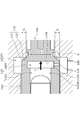
- the pressure in the oil chamber 123 is higher than the pressure in the oil chamber 121, the oil chamber 122, and the oil chamber 124. Further, as described above, since the oil chamber 123 and the oil chamber 125 communicate with each other through the drilling 116, the oil chamber 123 and the oil chamber 125 have the same pressure.
- the pressure receiving body 105 is pressed against the sealing body 104 by the pressure of the oil chamber 125.
- a force R in the valve opening direction acts on the spool 102.
- the pressure in the oil chamber 123 is the pressure P
- the pressure P is the area G in the axial direction of the outer diameter portion rather than the portion in contact with the opening edge 132 in the large diameter portion 131, that is, the opening in the large diameter portion 131.
- the area G in the axial direction of the outer diameter portion may be referred to as the axial viewing area G of the outer diameter portion.
- the recess 110 has a small-diameter recess 110A having an opening that opens into the oil chamber 124 (see FIG. 3), and a large-diameter recess 110B that has a larger diameter than the small-diameter recess 110A and has an end face 110a.
- the end face 110a has a pressure receiving portion G'as a pressure receiving surface to which the pressure P in the oil chamber 125 is applied.
- the pressure P in the oil chamber 125 is applied to the entire surface of the end face 110a.
- the force due to the pressure P applied to the direction and the valve opening direction is canceled out. Therefore, the portion of the end face 110a that acts in the valve closing direction, that is, the region excluding the outer diameter portion from the small diameter recess 110A from the end face 110a is referred to as the pressure receiving portion G'.
- valve open state of the spool type flow rate control valve 1 will be described with reference to FIGS. 6 and 7.
- the oil chamber 122 and the oil chamber 123 communicate with each other through a plurality of notches 112 provided on the outer peripheral surface of the second sliding portion 102b. Even if the spool 102 moves to the valve opening position, the oil chamber 121 and the oil chamber 122 are hermetically partitioned by the first sliding portion 102a, and the oil chamber 123 and the oil chamber 124 are third. It is partitioned in a sealed manner by the sliding portion 102c.
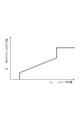
- FIG. 7 shows the relationship between the stroke of the spool 102 and the opening degree of the notch 112 (also referred to as the spool opening degree).
- the aspect of the spool type flow rate control valve 1 of this embodiment is shown by a solid line
- the aspect of the spool type flow rate control valve without a poppet valve is shown by a broken line.
- the horizontal axis of FIG. 7 indicates the stroke of the spool 102
- the vertical axis indicates the opening degree of the notch 112
- the spool type flow rate control valve 1 (solid line) has the opening degree of the notch 112 between the stroke 0 and the stroke U. It is closed at zero. It starts to open at the stroke U and reaches the maximum value Z at the stroke V.
- the section from the stroke 0 to the stroke U is a stroke until the wall portion 112a of the notch 112 reaches the opening edge 132 of the second inner diameter land portion 101B (see FIG. 3).
- the housing land portion and the spool land portion overlap in the axial direction in order to prevent oil from leaking between the housing land portion and the spool land portion. It is necessary to secure a long dimension of the wrapping portion, and in this case, the section from the stroke 0 to the stroke U'where the opening starts becomes long, and the control responsiveness deteriorates. Further, there is a problem that the section from the stroke U'to the stroke V, that is, the control range of the flow rate control curve is narrowed, and the controllability is deteriorated.
- the spool type flow rate control valve 1 (solid line) can finely control the spool opening degree. That is, the degree of freedom of the flow rate control curve is high. This is because the section from stroke 0 to stroke U can be shortened compared to the spool type flow rate control valve (broken line) without a poppet valve, so control responsiveness is good and the section from stroke U to stroke V is secured widely. Because it can be done.
- the tapered large diameter portion 131 extends toward the inner diameter side of the second outer diameter land portion 102B. Therefore, the large diameter portion 131 can be reliably seated on the opening edge 132 of the second inner diameter land portion 101B.
- the housing 101 is easy to manufacture.
- the spool 102 has an axial viewing area G of the outer diameter portion of the large diameter portion 131 to which the pressure in the oil chamber 123 is applied, and a pressure receiving portion G'which has the same area as the area G and is subject to the pressure in the oil chamber 125. And, the force R in the valve opening direction and the force T in the valve closing direction generated by applying pressure to the axial viewing area G and the pressure receiving portion G'of the outer diameter portion are offset and balanced. It has become so. According to this, the opening / closing control of the oil chamber 122 and the oil chamber 123 can be accurately performed by the spool 102.
- the pressure receiving body 105 is arranged in the recess 110 of the spool 102, the oil chamber 125 is partitioned by the recess 110 and the pressure receiving body 105, and the oil chamber 123 and the oil chamber 125 communicate with each other through the perforation 116. ..
- the end surface 110a of the recess 110 is provided with a pressure receiving portion G'having the same area as the axial viewing area G of the outer diameter portion.
- the oil chamber 123 and the oil chamber 125 can have the same pressure, and the oil chamber 123 and the oil chamber 125 are in the axial viewing area G and the pressure receiving portion G'of the outer diameter portion of the same area. Since the pressure of the spool 102 is applied, the force R in the valve opening direction and the force T in the valve closing direction of the spool 102 can be reliably and easily balanced.
- the pressure receiving body 105 is separate from the housing 101 and the sealing body 104, the assembly work is simple without requiring high accuracy when assembling the spool type flow rate control valve 1.
- the recess 110 and the pressure receiving body 105 slide. Therefore, it is possible to prevent the spool 102 from tilting when moving in the axial direction, and the spool 102 can be stably moved in the axial direction.
- the third outer diameter land portion 102C extends in the axial direction from the outer diameter of the large diameter portion 131, when assembling the spool type flow rate control valve 1, the spool is formed from the opening on the sealing body 104 side of the housing 101. Since the 102 can be inserted and arranged, the assembly work is simple, and the housing 101 can be composed of one member, the manufacturing and assembly of the housing 101 is also easy.
- the housing must be divided into multiple parts at the position of the poppet part that forms a large diameter, which increases the number of processes and complicates the structure. For example, when the housing is divided into a plurality of parts, it is necessary to align the axes of the two divided housings with each other, which makes processing difficult.
- the housing 101 can be formed as a single unit, which is easy to manufacture and process. become.
- the outer diameter portion and the pressure receiving surface have the same area, and the pressure of the same fluid is applied to the outer diameter portion and the pressure receiving surface to balance the forces on both sides in the axial direction of the spool.
- the present invention is not limited to this, and fluids having different pressures may be applied to the outer diameter portion and the pressure receiving surface to balance the forces on both sides in the axial direction of the spool. That is, the area of the outer diameter portion and the pressure receiving surface may be different from each other.
- the pressure receiving portion G'as the pressure receiving surface is provided on the end surface 110a of the recess 110 is exemplified, but the present invention is not limited to this, and the pressure receiving portion G'is axially opposed to the outer diameter portion of the large diameter portion. Any pressure receiving surface to which fluid pressure is applied in the valve closing direction can be freely changed.
- the housing 101 and the sealing body 104 are exemplified as separate bodies, but the present invention is not limited to this, and for example, the housing 101 or the sealing body 104 may be a portion integrally extending from the housing 101 or the sealing body 104.
- the spool type flow rate control valve 200 mainly includes a housing 201, a spool 202, sealing bodies 203 and 204, and a spring 206.
- the housing 201 is provided with a first inner diameter land portion 201A and a second inner diameter land portion 201B as a housing land portion separated from each other.
- a large diameter portion 201D is formed between the first inner diameter land portion 201A and the second inner diameter land portion 201B.
- a large-diameter recess 201E that opens toward the sealing body 204 is formed on the sealing body 204 side of the second inner diameter land portion 201B.
- the housing 201 is provided with a perforation 208 communicating with the regenerative oil passage 24 (see FIG. 1) and a perforation 209 communicating with the accumulator 7.
- the sealing body 204 has a U-shaped cross section, and the inner peripheral surface of the recess opening on the housing 201 side is the third inner diameter land portion 201C.
- the third inner diameter land portion 201C is formed to have the same diameter as the first inner diameter land portion 201A and the second inner diameter land portion 201B. Further, the sealing body 204 is formed with a perforation 215 communicating with the tank 12 (see FIG. 1).
- the spool 202 is provided with a first sliding portion 202a, a second sliding portion 202b, and a third sliding portion 202c.
- the first sliding portion 202a, the second sliding portion 202b, and the third sliding portion 202c have the same diameter.
- a large diameter portion 231 is formed on the sealing body 204 side of the second sliding portion 202b.
- the large diameter portion 231 is axially separated from the third sliding portion 202c, and the large diameter portion 231 and the third sliding portion 202c are connected by a small diameter portion 202e having a smaller diameter than the third sliding portion 202c. Has been done.
- the large diameter portion 231 and the opening edge 232 constitute the poppet valve 230.
- the spool 202 When pressure oil is supplied from the hydraulic pump 4 (see FIG. 1) into the oil chamber 221 through the drilling 203a, the spool 202 has an end portion of the third sliding portion 202c against the urging force of the spring 206. It moves in the valve opening direction until it abuts on the end of the sealing body 204. In this state, the oil chamber 222 and the oil chamber 223 communicate with each other through the notch 212.
- a hydraulic circuit has been described in which a part of the return oil is accumulated in the accumulator when the hydraulic cylinder contracts and the accumulated pressure oil is regenerated when the hydraulic cylinder expands.
- the pressure may be accumulated in the accumulator and the accumulated pressure oil may be regenerated when the hydraulic cylinder contracts.
- a part of the return oil generated when the other actuator is driven may be accumulated in the accumulator, and the accumulated pressure oil may be regenerated in the hydraulic cylinder. That is, it can be applied to various fluid circuits that perform accumulator and regeneration using an accumulator.
- the fluid control device is not limited to the one used for the hydraulic circuit of the excavator loader, and may be applied to the fluid circuit of a vehicle other than the excavator loader, a construction machine, an industrial machine, or the like.
- the pressure fluid used in the fluid circuit may be a liquid or gas other than oil.
- the fluid control device of the above embodiment illustrates a mode in which the valve closed state and the valve opened state are switched by the pilot hydraulic pressure from the hydraulic pump, but the present invention is not limited to this, and a spool type solenoid valve may be used. ..
Landscapes
- Engineering & Computer Science (AREA)
- General Engineering & Computer Science (AREA)
- Mechanical Engineering (AREA)
- Physics & Mathematics (AREA)
- Fluid Mechanics (AREA)
- Sliding Valves (AREA)
- Fluid-Pressure Circuits (AREA)
Priority Applications (4)
| Application Number | Priority Date | Filing Date | Title |
|---|---|---|---|
| US17/928,582 US12055225B2 (en) | 2020-06-04 | 2021-05-24 | Fluid control device |
| EP21818158.4A EP4163523B1 (en) | 2020-06-04 | 2021-05-24 | Fluid control device |
| JP2022528752A JP7777070B2 (ja) | 2020-06-04 | 2021-05-24 | 流体制御装置 |
| CN202180040270.3A CN115702301A (zh) | 2020-06-04 | 2021-05-24 | 流体控制装置 |
Applications Claiming Priority (2)
| Application Number | Priority Date | Filing Date | Title |
|---|---|---|---|
| JP2020097472 | 2020-06-04 | ||
| JP2020-097472 | 2020-06-04 |
Publications (1)
| Publication Number | Publication Date |
|---|---|
| WO2021246214A1 true WO2021246214A1 (ja) | 2021-12-09 |
Family
ID=78830962
Family Applications (1)
| Application Number | Title | Priority Date | Filing Date |
|---|---|---|---|
| PCT/JP2021/019530 Ceased WO2021246214A1 (ja) | 2020-06-04 | 2021-05-24 | 流体制御装置 |
Country Status (5)
| Country | Link |
|---|---|
| US (1) | US12055225B2 (https=) |
| EP (1) | EP4163523B1 (https=) |
| JP (1) | JP7777070B2 (https=) |
| CN (1) | CN115702301A (https=) |
| WO (1) | WO2021246214A1 (https=) |
Cited By (1)
| Publication number | Priority date | Publication date | Assignee | Title |
|---|---|---|---|---|
| WO2023243704A1 (ja) * | 2022-06-17 | 2023-12-21 | イーグル工業株式会社 | 加圧装置 |
Families Citing this family (3)
| Publication number | Priority date | Publication date | Assignee | Title |
|---|---|---|---|---|
| DE102022000767A1 (de) | 2022-03-04 | 2023-09-07 | Hydac Fluidtechnik Gmbh | Ventil |
| CA3197872A1 (en) * | 2022-05-09 | 2023-11-09 | Palamar Industries Inc. | Piston for adjustable pressure reducing valve and an adjustable pressure reducing valve |
| US20250383024A1 (en) * | 2024-06-17 | 2025-12-18 | General Electric Company | Pressure regulation valves |
Citations (2)
| Publication number | Priority date | Publication date | Assignee | Title |
|---|---|---|---|---|
| JPH0257779A (ja) * | 1988-08-24 | 1990-02-27 | Komatsu Ltd | ポペット弁装置 |
| JP2018168914A (ja) | 2017-03-29 | 2018-11-01 | 日立建機株式会社 | 方向制御弁及びそれを適用した油圧回路を備えた建設機械 |
Family Cites Families (16)
| Publication number | Priority date | Publication date | Assignee | Title |
|---|---|---|---|---|
| JPS5223722A (en) * | 1975-08-18 | 1977-02-22 | Matsushita Electric Industrial Co Ltd | Flow quantity control valve |
| US4238112A (en) * | 1978-12-22 | 1980-12-09 | Rexnord Inc. | Spool spin prevention for hydraulic control valves |
| JPS5682358U (https=) * | 1979-11-30 | 1981-07-03 | ||
| US4418612A (en) * | 1981-05-28 | 1983-12-06 | Vickers, Incorporated | Power transmission |
| JPS5917074A (ja) * | 1982-07-16 | 1984-01-28 | Hitachi Constr Mach Co Ltd | ロジツク弁 |
| JPS6319405A (ja) * | 1986-07-11 | 1988-01-27 | Toyooki Kogyo Co Ltd | 流量制御弁 |
| JP2577225B2 (ja) * | 1987-06-23 | 1997-01-29 | 株式会社小松製作所 | 流量制御弁 |
| US5271430A (en) * | 1988-08-16 | 1993-12-21 | Kabushiki Kaisha Komatsu Seisakusho | Flow rate control valve device and flow force reduction structure |
| WO1990002283A1 (fr) | 1988-08-24 | 1990-03-08 | Kabushiki Kaisha Komatsu Seisakusho | Dispositif a soupapes soulevantes |
| US5103866A (en) * | 1991-02-22 | 1992-04-14 | Foster Raymond K | Poppet valve and valve assemblies utilizing same |
| JP2604568Y2 (ja) | 1993-12-01 | 2000-05-22 | エヌオーケー株式会社 | 流体圧アクチュエータ |
| JP3679300B2 (ja) * | 1999-06-10 | 2005-08-03 | 日立建機株式会社 | 可変容量型液圧回転機の容量制御弁 |
| EP2282065B1 (de) * | 2009-07-30 | 2012-05-16 | HAWE Hydraulik SE | Hydraulisches Umschaltsitzventil und Leistungs-Trennschaltvorrichtung |
| US9657850B2 (en) | 2014-08-28 | 2017-05-23 | Proserv Operations, Inc. | High performance subsea pressure regulator |
| US9599238B2 (en) * | 2015-04-03 | 2017-03-21 | Caterpillar Inc. | Valve having improved spool geometry |
| JP7178837B2 (ja) | 2018-09-11 | 2022-11-28 | イーグル工業株式会社 | 流量制御弁 |
-
2021
- 2021-05-24 US US17/928,582 patent/US12055225B2/en active Active
- 2021-05-24 WO PCT/JP2021/019530 patent/WO2021246214A1/ja not_active Ceased
- 2021-05-24 JP JP2022528752A patent/JP7777070B2/ja active Active
- 2021-05-24 CN CN202180040270.3A patent/CN115702301A/zh active Pending
- 2021-05-24 EP EP21818158.4A patent/EP4163523B1/en active Active
Patent Citations (2)
| Publication number | Priority date | Publication date | Assignee | Title |
|---|---|---|---|---|
| JPH0257779A (ja) * | 1988-08-24 | 1990-02-27 | Komatsu Ltd | ポペット弁装置 |
| JP2018168914A (ja) | 2017-03-29 | 2018-11-01 | 日立建機株式会社 | 方向制御弁及びそれを適用した油圧回路を備えた建設機械 |
Non-Patent Citations (1)
| Title |
|---|
| See also references of EP4163523A4 |
Cited By (1)
| Publication number | Priority date | Publication date | Assignee | Title |
|---|---|---|---|---|
| WO2023243704A1 (ja) * | 2022-06-17 | 2023-12-21 | イーグル工業株式会社 | 加圧装置 |
Also Published As
| Publication number | Publication date |
|---|---|
| EP4163523A4 (en) | 2024-06-12 |
| US12055225B2 (en) | 2024-08-06 |
| EP4163523A1 (en) | 2023-04-12 |
| CN115702301A (zh) | 2023-02-14 |
| EP4163523B1 (en) | 2025-10-08 |
| JP7777070B2 (ja) | 2025-11-27 |
| US20230228342A1 (en) | 2023-07-20 |
| JPWO2021246214A1 (https=) | 2021-12-09 |
Similar Documents
| Publication | Publication Date | Title |
|---|---|---|
| WO2021246214A1 (ja) | 流体制御装置 | |
| CN110848384B (zh) | 液压系统以及机动车变速器 | |
| JP5233956B2 (ja) | オイル供給装置 | |
| US10233614B2 (en) | Fluid pressure control device | |
| JP5325781B2 (ja) | ソレノイドバルブ | |
| EP1531273B1 (en) | Counterbalance valve, and control unit and hydraulically powered system comprising the same | |
| JP6822930B2 (ja) | 流量制御弁 | |
| US7766042B2 (en) | Direct operated cartridge valve assembly | |
| US9803745B2 (en) | Oil supply device | |
| JP4929471B2 (ja) | 可変容量ベーンポンプ | |
| JP3502164B2 (ja) | 多連方向切換弁装置 | |
| JP5464275B2 (ja) | 油圧モータ用制御装置 | |
| JP6807828B2 (ja) | 弁装置 | |
| CN119365709A (zh) | 油压回路 | |
| JP7776928B2 (ja) | 弁及び流体圧システム | |
| CN111344494A (zh) | 油压控制阀 | |
| JP2006132683A (ja) | 油圧駆動ユニット | |
| JP2024176025A (ja) | 弁装置 | |
| JP4430377B2 (ja) | 弁装置 | |
| JP4604654B2 (ja) | ポンプ装置 | |
| JP2004108419A (ja) | ガスケット及びガスケットを備える多連弁 | |
| JP2003322105A (ja) | 油圧制御装置の取付構造 | |
| JP2002364602A (ja) | 液圧回路 | |
| JPH1122843A (ja) | ブレーキ弁 | |
| JP2020090942A5 (https=) |
Legal Events
| Date | Code | Title | Description |
|---|---|---|---|
| 121 | Ep: the epo has been informed by wipo that ep was designated in this application |
Ref document number: 21818158 Country of ref document: EP Kind code of ref document: A1 |
|
| ENP | Entry into the national phase |
Ref document number: 2022528752 Country of ref document: JP Kind code of ref document: A |
|
| NENP | Non-entry into the national phase |
Ref country code: DE |
|
| ENP | Entry into the national phase |
Ref document number: 2021818158 Country of ref document: EP Effective date: 20230104 |
|
| WWG | Wipo information: grant in national office |
Ref document number: 2021818158 Country of ref document: EP |