WO2021245974A1 - モータ制御装置およびモータ制御方法 - Google Patents
モータ制御装置およびモータ制御方法 Download PDFInfo
- Publication number
- WO2021245974A1 WO2021245974A1 PCT/JP2021/003174 JP2021003174W WO2021245974A1 WO 2021245974 A1 WO2021245974 A1 WO 2021245974A1 JP 2021003174 W JP2021003174 W JP 2021003174W WO 2021245974 A1 WO2021245974 A1 WO 2021245974A1
- Authority
- WO
- WIPO (PCT)
- Prior art keywords
- signal
- motor
- torque command
- pass filter
- output
- Prior art date
- Legal status (The legal status is an assumption and is not a legal conclusion. Google has not performed a legal analysis and makes no representation as to the accuracy of the status listed.)
- Ceased
Links
Images




Classifications
-
- B—PERFORMING OPERATIONS; TRANSPORTING
- B60—VEHICLES IN GENERAL
- B60L—PROPULSION OF ELECTRICALLY-PROPELLED VEHICLES; SUPPLYING ELECTRIC POWER FOR AUXILIARY EQUIPMENT OF ELECTRICALLY-PROPELLED VEHICLES; ELECTRODYNAMIC BRAKE SYSTEMS FOR VEHICLES IN GENERAL; MAGNETIC SUSPENSION OR LEVITATION FOR VEHICLES; MONITORING OPERATING VARIABLES OF ELECTRICALLY-PROPELLED VEHICLES; ELECTRIC SAFETY DEVICES FOR ELECTRICALLY-PROPELLED VEHICLES
- B60L15/00—Methods, circuits, or devices for controlling the traction-motor speed of electrically-propelled vehicles
- B60L15/20—Methods, circuits, or devices for controlling the traction-motor speed of electrically-propelled vehicles for control of the vehicle or its driving motor to achieve a desired performance, e.g. speed, torque, programmed variation of speed
-
- H—ELECTRICITY
- H02—GENERATION; CONVERSION OR DISTRIBUTION OF ELECTRIC POWER
- H02P—CONTROL OR REGULATION OF ELECTRIC MOTORS, ELECTRIC GENERATORS OR DYNAMO-ELECTRIC CONVERTERS; CONTROLLING TRANSFORMERS, REACTORS OR CHOKE COILS
- H02P21/00—Arrangements or methods for the control of electric machines by vector control, e.g. by control of field orientation
- H02P21/05—Arrangements or methods for the control of electric machines by vector control, e.g. by control of field orientation specially adapted for damping motor oscillations, e.g. for reducing hunting
-
- B—PERFORMING OPERATIONS; TRANSPORTING
- B60—VEHICLES IN GENERAL
- B60L—PROPULSION OF ELECTRICALLY-PROPELLED VEHICLES; SUPPLYING ELECTRIC POWER FOR AUXILIARY EQUIPMENT OF ELECTRICALLY-PROPELLED VEHICLES; ELECTRODYNAMIC BRAKE SYSTEMS FOR VEHICLES IN GENERAL; MAGNETIC SUSPENSION OR LEVITATION FOR VEHICLES; MONITORING OPERATING VARIABLES OF ELECTRICALLY-PROPELLED VEHICLES; ELECTRIC SAFETY DEVICES FOR ELECTRICALLY-PROPELLED VEHICLES
- B60L15/00—Methods, circuits, or devices for controlling the traction-motor speed of electrically-propelled vehicles
- B60L15/20—Methods, circuits, or devices for controlling the traction-motor speed of electrically-propelled vehicles for control of the vehicle or its driving motor to achieve a desired performance, e.g. speed, torque, programmed variation of speed
- B60L15/2009—Methods, circuits, or devices for controlling the traction-motor speed of electrically-propelled vehicles for control of the vehicle or its driving motor to achieve a desired performance, e.g. speed, torque, programmed variation of speed for braking
-
- B—PERFORMING OPERATIONS; TRANSPORTING
- B60—VEHICLES IN GENERAL
- B60L—PROPULSION OF ELECTRICALLY-PROPELLED VEHICLES; SUPPLYING ELECTRIC POWER FOR AUXILIARY EQUIPMENT OF ELECTRICALLY-PROPELLED VEHICLES; ELECTRODYNAMIC BRAKE SYSTEMS FOR VEHICLES IN GENERAL; MAGNETIC SUSPENSION OR LEVITATION FOR VEHICLES; MONITORING OPERATING VARIABLES OF ELECTRICALLY-PROPELLED VEHICLES; ELECTRIC SAFETY DEVICES FOR ELECTRICALLY-PROPELLED VEHICLES
- B60L2220/00—Electrical machine types; Structures or applications thereof
- B60L2220/40—Electrical machine applications
- B60L2220/42—Electrical machine applications with use of more than one motor
-
- B—PERFORMING OPERATIONS; TRANSPORTING
- B60—VEHICLES IN GENERAL
- B60L—PROPULSION OF ELECTRICALLY-PROPELLED VEHICLES; SUPPLYING ELECTRIC POWER FOR AUXILIARY EQUIPMENT OF ELECTRICALLY-PROPELLED VEHICLES; ELECTRODYNAMIC BRAKE SYSTEMS FOR VEHICLES IN GENERAL; MAGNETIC SUSPENSION OR LEVITATION FOR VEHICLES; MONITORING OPERATING VARIABLES OF ELECTRICALLY-PROPELLED VEHICLES; ELECTRIC SAFETY DEVICES FOR ELECTRICALLY-PROPELLED VEHICLES
- B60L2240/00—Control parameters of input or output; Target parameters
- B60L2240/40—Drive Train control parameters
- B60L2240/42—Drive Train control parameters related to electric machines
- B60L2240/421—Speed
-
- B—PERFORMING OPERATIONS; TRANSPORTING
- B60—VEHICLES IN GENERAL
- B60L—PROPULSION OF ELECTRICALLY-PROPELLED VEHICLES; SUPPLYING ELECTRIC POWER FOR AUXILIARY EQUIPMENT OF ELECTRICALLY-PROPELLED VEHICLES; ELECTRODYNAMIC BRAKE SYSTEMS FOR VEHICLES IN GENERAL; MAGNETIC SUSPENSION OR LEVITATION FOR VEHICLES; MONITORING OPERATING VARIABLES OF ELECTRICALLY-PROPELLED VEHICLES; ELECTRIC SAFETY DEVICES FOR ELECTRICALLY-PROPELLED VEHICLES
- B60L2240/00—Control parameters of input or output; Target parameters
- B60L2240/40—Drive Train control parameters
- B60L2240/42—Drive Train control parameters related to electric machines
- B60L2240/423—Torque
-
- B—PERFORMING OPERATIONS; TRANSPORTING
- B60—VEHICLES IN GENERAL
- B60L—PROPULSION OF ELECTRICALLY-PROPELLED VEHICLES; SUPPLYING ELECTRIC POWER FOR AUXILIARY EQUIPMENT OF ELECTRICALLY-PROPELLED VEHICLES; ELECTRODYNAMIC BRAKE SYSTEMS FOR VEHICLES IN GENERAL; MAGNETIC SUSPENSION OR LEVITATION FOR VEHICLES; MONITORING OPERATING VARIABLES OF ELECTRICALLY-PROPELLED VEHICLES; ELECTRIC SAFETY DEVICES FOR ELECTRICALLY-PROPELLED VEHICLES
- B60L2260/00—Operating Modes
- B60L2260/20—Drive modes; Transition between modes
- B60L2260/28—Four wheel or all wheel drive
-
- B—PERFORMING OPERATIONS; TRANSPORTING
- B60—VEHICLES IN GENERAL
- B60L—PROPULSION OF ELECTRICALLY-PROPELLED VEHICLES; SUPPLYING ELECTRIC POWER FOR AUXILIARY EQUIPMENT OF ELECTRICALLY-PROPELLED VEHICLES; ELECTRODYNAMIC BRAKE SYSTEMS FOR VEHICLES IN GENERAL; MAGNETIC SUSPENSION OR LEVITATION FOR VEHICLES; MONITORING OPERATING VARIABLES OF ELECTRICALLY-PROPELLED VEHICLES; ELECTRIC SAFETY DEVICES FOR ELECTRICALLY-PROPELLED VEHICLES
- B60L2260/00—Operating Modes
- B60L2260/40—Control modes
- B60L2260/44—Control modes by parameter estimation
-
- H—ELECTRICITY
- H02—GENERATION; CONVERSION OR DISTRIBUTION OF ELECTRIC POWER
- H02P—CONTROL OR REGULATION OF ELECTRIC MOTORS, ELECTRIC GENERATORS OR DYNAMO-ELECTRIC CONVERTERS; CONTROLLING TRANSFORMERS, REACTORS OR CHOKE COILS
- H02P27/00—Arrangements or methods for the control of AC motors characterised by the kind of supply voltage
- H02P27/04—Arrangements or methods for the control of AC motors characterised by the kind of supply voltage using variable-frequency supply voltage, e.g. inverter or converter supply voltage
- H02P27/06—Arrangements or methods for the control of AC motors characterised by the kind of supply voltage using variable-frequency supply voltage, e.g. inverter or converter supply voltage using DC to AC converters or inverters
-
- Y—GENERAL TAGGING OF NEW TECHNOLOGICAL DEVELOPMENTS; GENERAL TAGGING OF CROSS-SECTIONAL TECHNOLOGIES SPANNING OVER SEVERAL SECTIONS OF THE IPC; TECHNICAL SUBJECTS COVERED BY FORMER USPC CROSS-REFERENCE ART COLLECTIONS [XRACs] AND DIGESTS
- Y02—TECHNOLOGIES OR APPLICATIONS FOR MITIGATION OR ADAPTATION AGAINST CLIMATE CHANGE
- Y02T—CLIMATE CHANGE MITIGATION TECHNOLOGIES RELATED TO TRANSPORTATION
- Y02T10/00—Road transport of goods or passengers
- Y02T10/60—Other road transportation technologies with climate change mitigation effect
- Y02T10/64—Electric machine technologies in electromobility
-
- Y—GENERAL TAGGING OF NEW TECHNOLOGICAL DEVELOPMENTS; GENERAL TAGGING OF CROSS-SECTIONAL TECHNOLOGIES SPANNING OVER SEVERAL SECTIONS OF THE IPC; TECHNICAL SUBJECTS COVERED BY FORMER USPC CROSS-REFERENCE ART COLLECTIONS [XRACs] AND DIGESTS
- Y02—TECHNOLOGIES OR APPLICATIONS FOR MITIGATION OR ADAPTATION AGAINST CLIMATE CHANGE
- Y02T—CLIMATE CHANGE MITIGATION TECHNOLOGIES RELATED TO TRANSPORTATION
- Y02T10/00—Road transport of goods or passengers
- Y02T10/60—Other road transportation technologies with climate change mitigation effect
- Y02T10/72—Electric energy management in electromobility
Definitions
- the present invention relates to a motor control device and a motor control method.
- Patent Document 1 discloses a driving force control device for an electric vehicle for improving the processing speed and responsiveness of slip suppression control in the electric vehicle.
- the target torque is calculated based on the accelerator operation of the driver, the target acceleration is calculated, the actual motor rotation is detected and differentiated, and the actual acceleration is calculated. Then, the correction amount for the motor torque command value is calculated so that the deviation between the target acceleration and the actual acceleration becomes small, and the high-pass filter processing is performed on the calculated correction amount to calculate the correction torque. Further, the correction torque is added to the motor torque command value to calculate the control motor torque.
- Patent Document 1 controls the cutoff frequency of the high-pass filter to be smaller than that during normal driving to suppress slip when the vehicle starts or when slip is detected. is doing.
- Patent Document 1 is corrected to suppress torsional vibration.
- Patent Document 1 does not sufficiently correct for disturbance components such as brakes. The possibility of calculating the correction torque cannot be denied.
- the present invention has been made to solve the above-mentioned problems, and the purpose of the present invention is to suppress an error component due to a brake or the like even in a vehicle having a low resonance frequency so that the estimated motor speed is closer to the actual motor speed. It is to realize a motor control device and a motor control method that can improve the control accuracy of the motor.
- the present invention is configured as follows.
- the motor control device includes a controller that outputs a first torque command signal that commands the torque of the electric motor, and a vibration damping control unit.
- a motor speed signal which is the speed of the electric motor is input, a first high pass filter which outputs a first signal, and an estimated motor speed signal obtained from the first torque command signal are input.
- a second high-pass filter that outputs a second signal and a motor speed deviation signal that is a deviation between the first signal and the second signal are input, a low frequency component is acquired from the motor speed deviation signal, and a third signal is obtained. It has a low-pass filter that outputs as.
- a first torque command signal for commanding the torque of the electric motor is output from the controller, a motor speed signal which is the speed of the electric motor is input to the first high-pass filter, and the first signal is output. Then, the estimated motor speed signal obtained from the first torque command signal is input to the second high-pass filter, the second signal is output, and the motor speed deviation signal which is the deviation between the first signal and the second signal. Is input to the low-pass filter to acquire a low-frequency component from the motor speed deviation signal and output it.
- FIG. 1 It is a schematic block diagram of the electric vehicle to which the motor control device which concerns on Example 1 of this invention is applied. It is a block diagram of the vibration damping control system in Example 1.
- FIG. It is operation explanatory waveform diagram in the comparative example for demonstrating the effect by Example 1 of this invention. It is operation
- FIG. 1 is a schematic configuration diagram of an electric vehicle to which the motor control device according to the first embodiment of the present invention is applied.
- the electric vehicle shown in FIG. 1 is a front-wheel drive vehicle (two-wheel drive vehicle) in which the front wheels FL and FR are driven by the electric motor 1.
- a differential gear 3 is connected to the electric motor 1 via a reduction mechanism 2.
- a drive shaft 4 is connected to the differential gear 3.
- the front wheels FL and FR are connected to the drive shaft 4.
- Electric power is input to the electric motor 1 from a high voltage battery (not shown) via the inverter 5.
- the drive of the inverter 5 is controlled by the vehicle controller 6 and the controller in the inverter 5.
- the electric vehicle has a shift lever 12 that outputs a range position signal indicating the traveling mode of the vehicle, and an accelerator opening sensor 7 that outputs an accelerator opening signal.
- the vehicle controller 6 has a receiving unit that receives a range position signal from the shift lever 12 and an accelerator opening signal from the accelerator opening sensor 7.
- the vehicle controller 6 calculates the drive torque command value of the electric motor 1 based on the accelerator opening and the like, and drives the inverter 5 according to the drive torque command value.
- the inverter 5 has a receiving unit that receives the motor rotor position from the resolver 8, has a function of calculating the motor rotation speed from the motor rotor position, and has a second torque command signal and a motor rotation speed as inputs. It has a vibration damping control unit 500 (shown in FIG. 2) that calculates a torque command value.
- the shift lever 12 is operated by the driver, and is a parking range (P range) when the vehicle is stopped, a neutral range (N range) when the vehicle is not transmitting power, a drive range (D range) when moving forward, and a reverse range (reverse range) when moving backward.
- the range position signal of (R range) is output.
- the brake controller 9 is connected to the wheel speed sensors 10FL, 10FR, 10RR, and 10RR provided on each wheel FL, FR, RL, and RR, and receives the rotation speed signals of each wheel FL, FR, RL, and RR.
- the brake controller 9 adjusts the brake fluid output to the brake unit of each wheel FL, FR, RL, RR based on the amount of brake operation by the driver, and controls the braking torque of each wheel FL, FR, RL, RR. ..
- Information communication of the inverter 5, the vehicle controller 6, and the brake controller 9 is performed via the CAN communication line (communication device) 11.
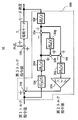
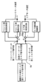
- FIG. 2 is a configuration diagram of the vibration damping control system 50 in the first embodiment.
- the first torque command value (first torque command signal) output from the controller 6 is output to the first subtractor 50a. Then, in the first subtractor 50a, the second torque command value (second torque command signal) output from the first amplifier 50k is subtracted from the first torque command value, and the third torque command value (third torque command) is subtracted. Signal) is calculated. The third torque command value is output to the first adder 50b, the disturbance is added, and the third torque command value is output to the electric motor 1 to be controlled.
- the first torque command value is input to the second subtractor 50e via the motor speed estimator 50c and the second high-pass filter 50d, which have overall vehicle inertia and integral characteristics and do not consider torsional vibration.
- the motor speed of the electric motor 1 is input to the first high-pass filter 50f.
- the signal output from the first high-pass filter 50f is input to the second subtractor 50e, and the output signal from the second high-pass filter 50d is subtracted.
- the signal subtracted by the second subtractor 50e is input to the second adder 50h via the low-pass filter 50g, and is added to the output signal of the second high-pass filter 50d.
- the output signal of the second adder 50h is input to the third subtractor 50i, and is subtracted from the output signal of the first high-pass filter 50f by the third subtractor 50i.
- the output signal of the third subtractor 50i is input to the first subtractor 50a via the third high-pass filter 50j and the first amplifier 50k.
- first subtractor 50a second subtractor 50e, third subtractor 50i, second adder 50h, motor speed estimator 50c, first high-pass filter 50f, second high-pass filter.
- a portion having 50d, a third high-pass filter 50j, a low-pass filter 50g, and a first amplifier 50k) is defined as a vibration damping control unit 500.
- the vibration damping control unit 500 is provided in the inverter 5. However, the vibration damping control unit 500 may be provided in the vehicle controller 6.
- the characteristics (H1 (s), H2 (s), H3 (s)) of the first high-pass filter 50f, the second high-pass filter 50d, and the third high-pass filter 50j are shown in the following equation (1).
- Gp (s) 1 / Js ... (3)
- i 1 to 3
- s is a Laplace operator, and since it is a continuous system, when it is implemented, each equation (1) to (3) is converted into a discrete system by bilinear transform or the like and used.
- ⁇ i and ⁇ 4 are cutoff angular frequencies, which determine the characteristics of each of the filters 50d, 50f, 50g, and 50j.
- H1 (s) and H2 (s) have equivalent properties.
- J is calculated as the motor side rotational inertia in consideration of the motor rotational inertia, the drive wheel rotational inertia, the vehicle weight, and the like.
- the high-pass filters 50f, 50d, 50j and the low-pass filter 50g may be other than the above equations (1) and (2) as long as they can obtain the same characteristics. Further, it may be a secondary filter instead of the primary filter. Further, J in the above equation (3) may be any other as long as it is calculated by regarding the drive system of the vehicle as one inertial system.
- the motor speed signal passes through the first high-pass filter 50f, and the first signal is obtained. Further, an estimated motor speed signal is obtained by inputting the first torque command signal to the motor speed estimator 50c, and the second signal is obtained by passing the estimated motor speed signal through the second high-pass filter 50d.
- the motor speed deviation signal which is the deviation between the first signal and the second signal (first signal-second signal)
- the low-pass filter 50 g passes through the low-pass filter 50 g, a low frequency component is acquired, and the third signal is obtained.
- the signal for adding the second signal and the third signal is subtracted from the first signal, and the feedback signal is acquired.
- the second torque command value (second torque command signal) based on this feedback signal is fed back to the first torque command value (first torque command signal) and output to the electric motor 1 to be controlled. It is a torque command value (third torque command signal).
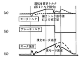
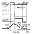
- FIG. 3 is an operation explanatory waveform diagram in a comparative example for explaining the effect according to the first embodiment of the present invention.
- the low-pass filter 50 g of the vibration damping control system 50 shown in FIG. 2 is omitted, and the deviation signal between the first signal and the second signal described above is used as a feedback signal, and this feedback signal is used. Then, based on this feedback signal, the command value is fed back to the first torque command value and output to the electric motor 1 to be controlled.
- FIG. 3A is a waveform of the motor torque
- the solid line shows the first torque command value which is the required torque of the driver
- the broken line shows the correction amount by the second torque command value.
- FIG. 3B shows the brake torque.
- FIG. 3C shows the motor speed
- the solid line shows the actual motor speed
- the broken line shows the estimated motor speed.
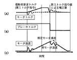
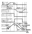
- FIG. 4 is an operation explanatory waveform diagram of the vibration damping control system 50 shown in FIG. 2 according to the first embodiment of the present invention shown in FIG.
- FIG. 4 is a waveform of the motor torque
- the solid line shows the first torque command value which is the required torque of the driver
- the broken line shows the correction amount by the second torque command value.
- FIG. 4B shows the brake torque.
- FIG. 4C shows the motor speed
- the solid line shows the actual motor speed
- the broken line shows the estimated motor speed. Comparing the waveform shown in FIG. 3 and the waveform shown in FIG. 4, the amount of correction by the second torque command value is different from that of Example 1 of the present invention shown in FIG. 4 in the comparative example shown in FIG. It can be understood that the larger one.
- the first high-pass filter 50f and the second high-pass filter 50d function so that the motor speed estimator 50c does not diverge, so that the estimation is different from the waveform of the estimated motor speed shown in FIGS. 3 and 4. It becomes the waveform of the motor speed. 3 and 4 have waveforms as shown for understanding the effect of the present invention.
- a motor control device and a motor control method capable of suppressing an error component due to a brake or the like, making the estimated motor speed closer to the actual motor speed, and improving the control accuracy of the motor. Can be realized.
- the first amplifier 50k is arranged, but it is also possible to omit the first amplifier 50k.
- Example 2 Next, Example 2 of the present invention will be described.
- FIG. 5 is a configuration diagram of the vibration damping control system 51 in the second embodiment.
- the difference between the vibration damping control system 50 in the first embodiment shown in FIG. 2 and the vibration damping control system 51 in the second embodiment shown in FIG. 5 is that the vibration damping control system 51 of the second embodiment is the first embodiment.
- a second amplifier 50m and a gain adjusting unit 50n are added to the vibration damping control system 50 of the above.
- the second amplifier 50m amplifies the output from the low-pass filter 50g with the gain adjusted by the gain adjusting unit 50n, and outputs the output to the second adder 50h.
- the gain adjusting unit 50n adjusts the gains of the first amplifier 50k and the second amplifier 50m according to the output value from the low-pass filter 50g.
- the gain adjustment unit 50n adjusts the gain of the second amplifier 50m.
- the gain adjusting unit 50n also adjusts the gain of the first amplifier 50k. By adjusting and lowering the gain of the first amplifier 50k, it is possible to suppress the influence on other controls by reducing the unexpected torque fluctuation generated due to the rapid change in the motor speed.
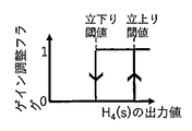
- FIG. 6 is an operation explanatory diagram of the gain adjusting unit 50n.
- the gain adjusting unit 50n reduces the gain 1 of the first amplifier 50k and the gain 2 of the second amplifier 50m when the output of the low-pass filter 50g becomes larger than a predetermined rise threshold value.
- the gain 2 is lowered, the influence of the low-pass filter 50g is reduced, so that the phase characteristics of the low-pass filter 50g can suppress the generation of torque that may hinder the operation of other controls during ABS operation or the like.
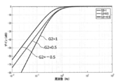
- FIG. 7 is a graph showing that the amplitude characteristics from the first high-pass filter 50f and the second high-pass filter 50d to the third high-pass filter 50j are changed by adjusting the gain of the second amplifier 50m
- FIG. 8 is a graph showing that the amplitude characteristics are changed. 2 It is a graph which shows that the phase characteristic from the 1st high-pass filter 50f and the 2nd high-pass filter 50d to the 3rd high-pass filter 50j changes by changing the gain of 2 amplifiers 50m.
- the phase characteristics of the first high-pass filter 50f and the second high-pass filter 50d to the third high-pass filter 50j can be changed by adjusting the gain of the second amplifier 50m.
- Example 9 and 10 are waveform diagrams for comparing the operations of Example 1 and Example 2.
- the correction torque in the second embodiment has a smaller difference from the first torque command than the correction torque of the first embodiment, and the fluctuation is also small.
- the actual motor speed in the second embodiment has a smaller difference from the target speed of the ABS than the actual motor speed of the first embodiment, and the fluctuation is also small.
- the first high-pass filter 50f and the second high-pass filter 50d function so that the motor speed estimator 50c does not diverge, so that the estimation is different from the waveform of the estimated motor speed shown in FIGS. 9 and 10. It becomes the waveform of the motor speed. 9 and 10 have waveforms as shown for understanding the effect of the second embodiment.
- the same effect as that of the first embodiment can be obtained, and the generation of torque that may hinder the slip control operation at the time of slipping can be suppressed.
- the configuration is not limited to the configuration shown in FIG. 5, and the configuration is converted into a form that can be regarded as equivalent in terms of the control configuration. May be good.
- Example 3 of the present invention will be described.
- Example 3 of the present invention is an example in which the present invention is applied to a four-wheel drive vehicle.
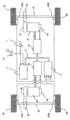
- FIG. 11 is a schematic configuration diagram of an electric vehicle to which the motor control device according to the third embodiment of the present invention is applied.
- the electric vehicle shown in FIG. 1 has an electric motor for rear wheels 1R, a reduction mechanism for rear wheels 2R, a differential gear 3R for rear wheels, a drive shaft 4R, an inverter 5R for rear wheels, and a rear wheel.
- Resolver 8R for use has been added.
- the electric motor 1, the reduction mechanism 2, the differential gear 3, the drive shaft 4, the inverter 5, and the resolver 8 in FIG. 1 are the front wheel electric motor 1F, the reduction mechanism 2F, and the front wheel differential for convenience of the explanation of the third embodiment. It has a gear 3F, a front wheel drive shaft 4F, a front wheel inverter 5F, and a front wheel resolver 8F.
- the differential gear 3R is connected to the rear wheel electric motor 1R via the reduction mechanism 2R.
- a drive shaft 4R is connected to the differential gear 3R.
- the rear wheels RL and RR are connected to the drive shaft 4R.
- the rear wheel electric motor 1R outputs electric power from a high-voltage battery (not shown) via the inverter 5R.
- the drive of the inverter 5R is controlled by the vehicle controller 6 and the controller in the inverter 5.
- the brake controller 9 is connected to the wheel speed sensors 10FL, 10FR, 10RR, 10RR provided on each wheel RL, RR, and receives the rotation speed signals of each wheel FL, FR, RL, RR.
- the brake controller 9 adjusts the brake fluid output to the brake unit of each wheel FL, FR, RL, RR based on the amount of brake operation by the driver, and controls the braking torque of each wheel FL, FR, RL, RR. ..
- Information communication of the rear wheel inverter 5R, the vehicle controller 6, and the brake controller 9 is performed via the CAN communication line (communication device) 11.
- the vibration damping control unit 500 shown in FIG. 2 is provided with another vibration damping control unit 500 for rear wheel drive in addition to the front wheel drive. It is considered good.
- FIG. 12 is a schematic configuration explanatory diagram in the case where the vibration damping control unit 500 shown in FIG. 2 is simply provided with another vibration damping control unit 500 for rear wheel drive in addition to the front wheel drive.
- the torque command distribution unit 6a of the controller 6 to the front and rear motors gives a first torque command to the front wheel electric motor 1F, which is a front motor, when the first torque command value requested by the driver is output.
- the value is output to the front wheel electric motor 1F, which is the control target on the front side, via the first subtractor 50a.
- the front side vibration damping control unit 500F (referred to as the front side vibration damping control unit 500F because it has the same configuration as the vibration damping control unit 500 and is the front side control unit) is the front motor speed from the front side control target.
- the first torque command value to the front motor 1F is output. Then, the front side vibration damping control unit 500F outputs a feedback signal to the first subtractor 50a.
- the torque command distribution unit 6a to the front and rear wheel electric motors 1F and 1R transfers the first torque command value to the rear wheel electric motor 1R, which is a rear motor, via the fourth subtractor 50p to the rear wheel electric motor. Output to 1R.
- the rear side vibration damping control unit 500R (referred to as the rear side vibration damping control unit 500R because it has the same configuration as the vibration damping control unit 500 and is the rear side control unit) has the rear motor speed and the rear motor speed from the rear side control target.
- the first torque command value to the rear motor 1R is output.
- the rear side vibration damping control unit 500R outputs a feedback signal to the fourth subtractor 50p.
- the motor speed estimator 50c estimates the motor speed, but in the configuration shown in FIG. 12, only the torque command to each electric motor 1F and 1R is used. The motor speed cannot be estimated.
- the motor speed is determined by the total value of the torque command values for the front and rear wheel electric motors 1F and 1R (that is, the torque required by the driver).
- FIG. 13 is a schematic configuration diagram of a motor control device according to a third embodiment in which the present invention is applied to a four-wheel drive vehicle.
- the first torque command value requested by the driver is input to the torque command distribution unit 6a of the controller 6 to the electric motors for the front and rear wheels.
- the first torque command value requested by the driver is output to the torque command distribution unit 6a, and the front side vibration damping control unit (front wheel vibration damping control unit) 500F and the rear side vibration damping control unit (rear wheel damping control unit) are output. Vibration control unit) It is also output to 500R.
- the torque command distribution unit 6a outputs the first torque command value to the front wheel electric motor 1F, which is the front motor, to the front wheel electric motor 1F, which is the control target on the front side, via the first subtractor 50a.
- the front motor speed from the front side control target is input to the front side vibration damping control unit 500F.
- the front side vibration damping control unit 500F outputs a feedback signal to the first subtractor 50a.
- the torque command distribution unit 6a to the front and rear motors applies the first torque command value to the rear wheel electric motor 1R, which is the rear motor, via the fourth subtractor 50p to the rear wheel electric motor to be controlled on the rear side. Output to motor 1R.
- the rear motor speed from the rear control target is input to the rear vibration damping control unit 500R. Then, the rear side vibration damping control unit 500R outputs a feedback signal to the fourth subtractor 50p.
- the torque command values to the front and rear wheel electric motors 1F and 1R are the same as the actual motor speed. It becomes possible to estimate the motor speed based on the total value (that is, the torque required by the driver).
- the front side vibration damping control unit 500F and the front side vibration damping control unit 500F which become a problem when the motor speed is estimated by the front side vibration damping control unit 500F and the rear side vibration damping control unit 500R based only on the torque command value from the torque command distribution unit 6a. It is possible to suppress the deviation that occurs between the motor speed estimated by the rear vibration damping control unit 500R and the actual motor speed, and by making an erroneous correction, it is possible to suppress the occurrence of a situation in which acceleration / deceleration is hindered. be able to.
- the same effect as that of the first embodiment can be obtained even in the four-wheel drive vehicle.
- the vibration damping control unit 500 shown in the first embodiment is applied as the front side vibration damping control unit 500F and the rear side vibration damping control unit 500R.
- the example of FIG. 5 (Example 2) in which the second amplifier 50 m and the gain adjusting unit 50n are added to the vibration damping control unit 500 shown in 1 can be used as the vibration damping control units 500F and 500R. In that case, the same effect as in the second embodiment can be obtained even in the four-wheel drive vehicle.
- second subtractor 50f ... first high-pass filter, 50g ... low-pass filter, 50h ... 2nd adder, 50i ... 3rd subtractor, 50j ... 3rd high pass filter, 50k ... 1st amplifier, 50m ... 2nd amplifier, 50n ... gain adjuster, 50p ... ⁇ Fourth subtractor, 500, 500F, 500R ... Vibration suppression control unit
Landscapes
- Engineering & Computer Science (AREA)
- Power Engineering (AREA)
- Transportation (AREA)
- Mechanical Engineering (AREA)
- Control Of Electric Motors In General (AREA)
- Electric Propulsion And Braking For Vehicles (AREA)
- Control Of Ac Motors In General (AREA)
Abstract
本発明の課題は、ブレーキ等による誤差成分を抑制して、推定モータ速度を実モータ速度により近づけ、モータの制御精度を向上可能なモータ制御装置を実現することである。 モータ制御装置は、電動モータ1のトルクを指令する第1トルク指令信号を出力するコントローラ6と、制振制御部500とを備える。制振制御部500は、電動モータ1の速度であるモータ速度信号が入力され、第1信号を出力する第1ハイパスフィルタ50fと、記第1トルク指令信号から得られる推定モータ速度信号が入力され、第2信号を出力する第2ハイパスフィルタ50dと、第1信号と第2信号との偏差であるモータ速度偏差信号が入力され、モータ速度偏差信号から低周波成分を取得し、第3信号として出力するローパスフィルタ50gとを有する。
Description
本発明は、モータ制御装置およびモータ制御方法に関する。
電気自動車に使用されるモータの制御精度を向上し、応答性を向上して運転者に対する操作性向上が望まれている。
特許文献1には、電動車両におけるスリップ抑制制御の処理速度や応答性を向上するための電動車両の駆動力制御装置が開示されている。
特許文献1に記載の技術においては、運転者のアクセル操作に基づいて目標トルクを算出して、目標加速度を演算し、実際のモータ回転を検出して微分し、実加速度を演算している。そして、目標加速度と実加速度との偏差が小さくなるように、モータトルク指令値に対する補正量を演算し、演算した補正量に対してハイパスフィルタ処理を行って、補正トルクを演算している。さらに、モータトルク指令値に補正トルクを加算し、制御用モータトルクを算出している。
そして、特許文献1に記載の技術は、車両の発進時、又は、スリップ検出時に、ハイパスフィルタのカットオフ周波数を、通常走行時と比較して小さくなるように切り換えてスリップを抑制するように制御している。
また、特許文献1に記載の技術は、捻じれ振動を抑制するための補正が行われている。
また、特許文献1に示された技術においては、ブレーキ操作や勾配抵抗などの外乱トルクによるモータの速度変化を振動として捉え、補正トルクを算出してしまう可能性があるため、シミュレータ追従制御に対しハイパスフィルタを追加し、この課題に対する解決が図られている。
しかしながら、共振周波数が低い車両においては、ねじり振動によるモータ速度変動とブレーキ等の外乱によるモータ速度変動との切り分けが困難となり、特許文献1の構成ではブレーキ等の外乱成分に対する補正が十分でなく、補正トルクを算出してしまう可能性を否定することができない。
本発明は、上述のような課題を解決するためになされたもので、その目的は共振周波数が低い車両においても、ブレーキ等による誤差成分を抑制して、推定モータ速度を実モータ速度により近づけ、モータの制御精度を向上可能なモータ制御装置およびモータ制御方法を実現することである。
上記目的を達成するため、本発明は次のように構成される。
モータ制御装置は、電動モータのトルクを指令する第1トルク指令信号を出力するコントローラと、制振制御部とを備える。前記制振制御部は、前記電動モータの速度であるモータ速度信号が入力され、第1信号を出力する第1ハイパスフィルタと、前記第1トルク指令信号から得られる推定モータ速度信号が入力され、第2信号を出力する第2ハイパスフィルタと、前記第1信号と前記第2信号との偏差であるモータ速度偏差信号が入力され、前記モータ速度偏差信号から低周波成分を取得し、第3信号として出力するローパスフィルタとを有する。
また、モータ制御方法において、コントローラから電動モータのトルクを指令する第1トルク指令信号を出力し、前記電動モータの速度であるモータ速度信号を第1ハイパスフィルタに入力して、第1信号を出力し、前記第1トルク指令信号から得られる推定モータ速度信号を第2ハイパスフィルタに入力して、第2信号を出力し、前記第1信号と前記第2信号との偏差であるモータ速度偏差信号をローパスフィルタに入力して、前記モータ速度偏差信号から低周波成分を取得して出力する。
ブレーキ等による誤差成分を抑制して、推定モータ速度を実モータ速度により近づけ、モータの制御精度を向上可能なモータ制御装置およびモータ制御方法を実現することができる。
以下、本発明の実施形態について添付図面を参照して説明する。
(実施例1) 図1は、本発明の実施例1に係るモータ制御装置が適用される電動車両の概略構成図である。
図1に示した電動車両は、前輪FL、FRが電動モータ1により駆動される前輪駆動車(2輪駆動車)である。電動モータ1には減速機構2を介してディファレンシャルギア3が接続されている。ディファレンシャルギア3にはドライブブシャフト4が接続されている。ドライブシャフト4には前輪FL、FRが接続されている。
電動モータ1には、インバータ5を介して高電圧バッテリ(図示せず)から電力が入力される。インバータ5の駆動は、車両コントローラ6及びインバータ5内の制御器により制御される。
電動車両は、車両の走行モードを表すレンジ位置信号を出力するシフトレバー12と、アクセル開度信号を出力するアクセル開度センサ7とを有する。車両コントローラ6は、シフトレバー12からのレンジ位置信号と、アクセル開度センサ7からのアクセル開度信号とを受信する受信部を有する。
車両コントローラ6は、アクセル開度等に基づいて電動モータ1の駆動トルク指令値を演算し、駆動トルク指令値に応じてインバータ5を駆動する。インバータ5はレゾルバ8からのモータ回転子位置を受信する受信部を有し、モータ回転子位置からモータ回転速度を演算する機能を有し、第1トルク指令信号とモータ回転速度を入力として第2トルク指令値を算出する制振制御部500(図2に示す)を有する。
シフトレバー12は、運転者により操作され、車両停車時はパーキングレンジ(Pレンジ)、非動力伝達時はニュートラルレンジ(Nレンジ)、前進時はドライブレンジ(Dレンジ)、後退時はリバースレンジ(Rレンジ)のレンジ位置信号を出力する。
ブレーキコントローラ9は、各車輪FL、FR、RL、RRに設けられた車輪速センサ10FL、10FR、10RL、10RRと接続され、各車輪FL、FR、RL、RRの回転速度信号を受信する。ブレーキコントローラ9は、運転者のブレーキ操作量に基づき、各車輪FL、FR、RL、RRのブレーキユニットに出力するブレーキ液を調整し、各車輪FL、FR、RL、RRの制動トルクを制御する。インバータ5、車両コントローラ6およびブレーキコントローラ9の情報通信は、CAN通信線(通信装置)11を介して行われる。
図2は、実施例1における制振制御系50の構成図である。
図2において、コントローラ6から出力された第1トルク指令値(第1トルク指令信号)は、第1減算器50aに出力される。そして、第1減算器50aにおいて、第1トルク指令値から、第1増幅器50kから出力される第2トルク指令値(第2トルク指令信号)が減算され、第3トルク指令値(第3トルク指令信号)が算出される。第3トルク指令値は第1加算器50bに出力され、外乱が加算されて、制御対象である電動モータ1に出力される。
また、第1トルク指令値は、オーバーオールの車両慣性と積分特性を有し、ねじり振動を考慮しないモータ速度推定器50c及び第2ハイパスフィルタ50dを介して第2減算器50eに入力される。電動モータ1のモータ速度は、第1ハイパスフィルタ50fに入力される。そして、第1ハイパスフィルタ50fから出力された信号が、第2減算器50eに入力され、第2ハイパスフィルタ50dからの出力信号が減算される。
第2減算器50eで減算処理された信号は、ローパスフィルタ50gを介して第2加算器50hに入力され、第2ハイパスフィルタ50dの出力信号と加算される。第2加算器50hの出力信号は、第3減算器50iに入力され、この第3減算器50iにて第1ハイパスフィルタ50fの出力信号から減算される。
そして、第3減算器50iの出力信号は、第3ハイパスフィルタ50j及び第1増幅器50kを介して第1減算器50aに入力される。
図2の破線で囲った各素子(第1減算器50a、第2減算器50e、第3減算器50i、第2加算器50h、モータ速度推定器50c、第1ハイパスフィルタ50f、第2ハイパスフィルタ50d、第3ハイパスフィルタ50j、ローパスフィルタ50g、第1増幅器50k)を有する部分を制振制御部500と定義する。
制振制御部500は、インバータ5内に備えられている。ただし、制振制御部500は、車両コントローラ6内に備えられものであってもよい。
第1ハイパスフィルタ50f、第2ハイパスフィルタ50d、第3ハイパスフィルタ50jの特性(H1(s)、H2(s)、H3(s))を次式(1)に示す。
Hi(s)=s/(s+ωi) ・・・(1)
また、ローパスフィルタ50gの特性H4(s)を次式(2)に示す。
また、ローパスフィルタ50gの特性H4(s)を次式(2)に示す。
H4(s)=ω4/(s+ω4) ・・・(2)
また、モータ速度推定器50cの特性Gp(s)を次式(3)に示す。
また、モータ速度推定器50cの特性Gp(s)を次式(3)に示す。
Gp(s)=1/Js ・・・(3)
上記(1)式、(2)式、(3)式において、iは1~3であり、sはラプラス演算子であり、連続系のため、実装する場合には、各式(1)~(3)を双一次変換等により離散系に変換して使用する。
上記(1)式、(2)式、(3)式において、iは1~3であり、sはラプラス演算子であり、連続系のため、実装する場合には、各式(1)~(3)を双一次変換等により離散系に変換して使用する。
また、ωi、ω4はカットオフ角周波数であり、各フィルタ50d、50f、50g、50jの特性を決定するものである。実施例1においては、少なくとも、H1(s)とH2(s)は等価な特性を有する。また、Jは、モータ回転慣性、駆動輪回転慣性、車両重量等を加味してモータ側回転慣性として算出したものである。
なお、ハイパスフィルタ50f、50d、50j、ローパスフィルタ50gは、同様の特性を得られるものであれば、上記式(1)、式(2)以外のものでもよい。また、1次フィルタではなく、2次フィルタであってもよい。また、上記式(3)のJは、車両の駆動系を1慣性系と見立てて算出されたものであれば、他のものでもよい。
制振制御系50においては、モータ速度信号が第1ハイパスフィルタ50fを通過して、第1信号が得られる。また、第1トルク指令信号をモータ速度推定器50cに入力することにより推定モータ速度信号が得られ、この推定モータ速度信号が第2ハイパスフィルタ50dを通過することにより、第2信号が得られる。
そして、第1信号と第2信号との偏差(第1信号-第2信号)であるモータ速度偏差信号はローパスフィルタ50gを通過して、低周波成分が取得され、第3信号が得られる。第1信号から、第2信号と第3信号を加算した信号を減算し、フィードバック用信号を取得する。そして、このフィードバック用信号に基づく第2トルク指令値(第2トルク指令信号)を、第1トルク指令値(第1トルク指令信号)にフィードバックして制御対象である電動モータ1に出力する第3トルク指令値(第3トルク指令信号)としている。
これによって、ブレーキ操作や勾配走行によるモータ速度変化を振動と捉え、補正トルクを算出してしまうということを十分に抑制することができ、運転者に違和感を与えるトルク変化を低減することができる。
図3は、本発明の実施例1による効果を説明するための比較例における動作説明波形図である。図3に示した波形は、図2に示した制振制御系50のローパスフィルタ50gを省略し、上述した第1信号と第2信号との偏差信号をフィードバック信号とし、このフィードバック信号としている。そして、このフィードバック信号に基づいて、第1トルク指令値にフィードバックして制御対象である電動モータ1に出力する指令値としている。
図3の(A)は、モータトルクの波形であり、実線は運転者の要求トルクである第1トルク指令値を示し、破線は第2トルク指令値による補正量を示す。図3の(B)は、ブレーキトルクを示す。図3の(C)は、モータ速度を示し、実線は実モータ速度を示し、破線は推定モータ速度を示す。図4は、図2に示した本発明の実施例1による図2に示した制振制御系50の動作説明波形図である。
図4の(A)は、モータトルクの波形であり、実線は運転者の要求トルクである第1トルク指令値を示し、破線は第2トルク指令値による補正量を示す。図4の(B)は、ブレーキトルクを示す。図4の(C)は、モータ速度を示し、実線は実モータ速度を示し、破線は推定モータ速度を示す。図3に示した波形と図4に示した波形を比較すると、第2トルク指令値による補正量は、図4に示した本発明の実施例1の場合より、図3に示した比較例の方が大きいことが理解できる。
また、推定モータ速度と実モータ速度と差は、図4に示した本発明の実施例1の場合より、図3に示した比較例の方が大きいことが理解できる。
これは、図3に示した比較例は、ローパスフィルタ50gが無く、ブレーキ操作や勾配走行によるモータ速度変化を振動と捉えて、補正トルクを算出してしまうからである。
ただし、実際には、第1ハイパスフィルタ50fと第2ハイパスフィルタ50dにより、モータ速度推定器50cが発散しないように機能するため、図3及び図4に示した推定モータ速度の波形とは異なる推定モータ速度の波形となる。図3及び図4は、本発明の効果の理解のために図示したような波形となっている。
以上のように、本発明の実施例1によれば、ブレーキ等による誤差成分を抑制して、推定モータ速度を実モータ速度により近づけ、モータの制御精度を向上可能なモータ制御装置およびモータ制御方法を実現することができる。
なお、図2に示した例においては、第1増幅器50kが配置されているが、この第1増幅器50kを省略することも可能である。
(実施例2)
次に、本発明の実施例2について説明する。
次に、本発明の実施例2について説明する。
図5は、実施例2における制振制御系51の構成図である。
実施例2が適用される電動車両は、実施例1と同様な構成であるので、図示及び詳細な説明は省略する。
図2に示した実施例1における制振制御系50と、図5に示した実施例2における制振制御系51との相違点は、実施例2の制振制御系51は、実施例1の制振制御系50に第2増幅器50mと、ゲイン調整部50nが追加されているところである。
第2増幅器50mは、ローパスフィルタ50gからの出力をゲイン調整部50nにより調整されるゲインで増幅し、第2加算器50hに出力する。ゲイン調整部50nは、ローパスフィルタ50gからの出力値に応じて、第1増幅器50k及び第2増幅器50mのゲインを調整する。
ローパスフィルタ50gが有する位相特性によりABS動作時などにおいては他の制御の動作を阻害する恐れがあるトルクが発生する場合がある。このため、ローパスフィルタ50gの出力値を第2増幅器50mのゲインを調整して低下させることにより、他の制御の動作を阻害する恐れがあるトルクの発生を抑制することができる。
第2増幅器50mのゲインの調整は、ゲイン調整部50nが行う。
ゲイン調整部50nは、第1増幅器50kのゲインも調整する。第1増幅器50kのゲインを調整して低下させることにより、モータ速度変化が速いために発生する予期せぬトルク変動を低減することで、他の制御への影響を抑制することができる。
図6は、ゲイン調整部50nの動作説明図である。図6において、ゲイン調整部50nは、ローパスフィルタ50gの出力が予め定めた立上り閾値より大きくなった場合、第1増幅器50kのゲイン1と第2増幅器50mのゲイン2を低下させる。ゲイン2を低下させるとローパスフィルタ50gの影響が低下するため、ローパスフィルタ50gが有する位相特性によりABS動作時等において、他の制御の動作を阻害する恐れがあるトルクの発生を抑制できる。
さらに、第1増幅器50kのゲインを低下させることで、制振制御が電動車両に与える影響が低下するため、他の制御の動作を阻害することを抑制する。これにより、ABS動作時に制振制御のトルク指令により制動性能が劣化することを抑制でき、停車距離が伸びることを抑制することができる。
図7は、第2増幅器50mのゲインの調整により、第1ハイパスフィルタ50f及び第2ハイパスフィルタ50dから第3ハイパスフィルタ50jまでの振幅特性が変化することを示すグラフであり、図8は、第2増幅器50mのゲインの変更により、第1ハイパスフィルタ50f及び第2ハイパスフィルタ50dから第3ハイパスフィルタ50jまでの位相特性が変化することを示すグラフである。
図7及び図8において、第2増幅器50mのゲインをG2とし、G2を1、2、-0.5に変更した場合の周波数特性の変化を示している。
図7及び図8に示すように、第2増幅器50mのゲインの調整により、第1ハイパスフィルタ50f及び第2ハイパスフィルタ50dから第3ハイパスフィルタ50jまでの位相特性を変更することができる。
図9及び図10は、実施例1と実施例2との動作を比較するための波形図である。
図9において、実施例1は、ゲインの調整が無いため、ゲインは変化していない。一方。図10において、実施例2は、ゲインを調整しているため、ゲインが変化している。
このため、実施例2における補正トルクは、実施例1の補正トルクより第1トルク指令との差が少なく、変動も小さい。また、実施例2における実モータ速度は、実施例1の実モータ速度よりABSの目標速度との差が少なく、変動も小さい。
ただし、実際には、第1ハイパスフィルタ50fと第2ハイパスフィルタ50dにより、モータ速度推定器50cが発散しないように機能するため、図9及び図10に示した推定モータ速度の波形とは異なる推定モータ速度の波形となる。図9及び図10は、実施例2の効果の理解のために図示したような波形となっている。
本発明の実施例2によれば、実施例1と同様な効果が得られる他、スリップ時にスリップ制御の動作を阻害する恐れがあるトルクの発生を抑制することができる。
なお、図5に示した制振制御系51と同等の効果を得ることができるのであれば、図5に示した構成に限らず、制御構成上、同等とみなせる形に変換した構成であってもよい。
(実施例3)
次に、本発明の実施例3について説明する。
次に、本発明の実施例3について説明する。
本発明の実施例3は、本発明を4輪駆動車に適用した例である。
図11は、本発明の実施例3に係るモータ制御装置が適用される電動車両の概略構成図である。
図11に示した例は、図1に示した電動車両に、後輪用電動モータ1R、後輪用減速機構2R、後輪用ディファレンシャルギア3R、ドライブシャフト4R、後輪用インバータ5R、後輪用レゾルバ8Rが追加されている。
なお、図1における電動モータ1、減速機構2、ディファレンシャルギア3,ドライブシャフト4、インバータ5、レゾルバ8は、実施例3の説明の都合上、前輪用電動モータ1F、減速機構2F、前輪用ディファレンシャルギア3F、前輪ドライブシャフト4F、前輪用インバータ5F、前輪用レゾルバ8Fとしている。
図11において、後輪用電動モータ1Rには減速機構2Rを介してディファレンシャルギア3Rが接続されている。ディファレンシャルギア3Rにはドライブシャフト4Rが接続されている。ドライブシャフト4Rには後輪RL、RRが接続されている。
後輪用電動モータ1Rは、インバータ5Rを介して高電圧バッテリ(図示せず)から電力が出力される。インバータ5Rの駆動は、車両コントローラ6及びインバータ5内の制御器により制御される。
ブレーキコントローラ9は、各車輪RL、RRに設けられた車輪速センサ10FL,10FR、10RL、10RRと接続され、各車輪FL、FR、RL、RRの回転速度信号を受信する。ブレーキコントローラ9は、運転者のブレーキ操作量に基づき、各車輪FL、FR、RL、RRのブレーキユニットに出力するブレーキ液を調整し、各車輪FL、FR、RL、RRの制動トルクを制御する。後輪用インバータ5R、車両コントローラ6およびブレーキコントローラ9の情報通信は、CAN通信線(通信装置)11を介して行われる。
図11に示した電動車両の他の動作は、図1に示した電動車両と同様となっている。
ここで、本発明を4輪駆動車に適用する場合、図2に示した制振制御部500を前輪駆動用の他に後輪駆動用にもう一つ他の制振制御部500を備えればよいと考えられる。
しかしながら、単にもう一つ他の制振制御部500を備えるのでは、良好な動作制御を行えない場合が発生する。以下にその理由を説明する。
図12は、図2に示した制振制御部500を前輪駆動用の他に後輪駆動用にもう一つ他の制振制御部500を単に備えた場合の概略構成説明図である。
図12において、コントローラ6が有する前後モータへのトルク指令分配部6aは、運転手の要求する第1トルク指令値が出力されると、フロントモータである前輪用電動モータ1Fへの第1トルク指令値を、第1減算器50aを介してフロント側制御対象である前輪用電動モータ1Fに出力する。フロント側制振制御部500F(制振制御部500と同等の構成であり、フロント側の制御部であるので、フロント側制振制御部500Fとする)は、フロント側制御対象からのフロントモータ速度及びフロントモータ1Fへの第1トルク指令値が出力される。そして、フロント側制振制御部500Fは、第1減算器50aにフィードバック信号を出力する。
また、前後輪用電動モータ1F、1Rへのトルク指令分配部6aは、リアモータである後輪用電動モータ1Rへの第1トルク指令値を、第4減算器50pを介して後輪用電動モータ1Rに出力する。リア側制振制御部500R(制振制御部500と同等の構成であり、リア側の制御部であるので、リア側制振制御部500Rとする)は、リア側制御対象からのリアモータ速度及びリアモータ1Rへの第1トルク指令値が出力される。そして、リア側制振制御部500Rは、第4減算器50pにフィードバック信号を出力する。
フロント側制振制御部500F及びリア側制振制御部500Rのうち、モータ速度推定器50cはモータ速度推定を行うが、図12に示した構成では各電動モータ1F、1Rへのトルク指令分しかモータ速度を推定できない。
しかしながら、実際のモータは前後輪電動モータ1F、1Rへのトルク指令値の合算値(つまり運転手の要求トルク)によりモータ速度が決定される。
そのため,図12に示した構成では、フロント側制振制御部500F及びリア側制振制御部500Rで推定したモータ速度と実際のモータ速度との間にずれが発生し、誤った補正を行うことで、加減速を阻害する恐れがある。
図13は、本発明を4輪駆動車に適用した実施例3であるモータ制御装置の概略構成図である。
図13において、コントローラ6が有する前後輪用電動モータへのトルク指令分配部6aには、運転手の要求する第1トルク指令値が入力される。
運転手の要求する第1トルク指令値は、トルク指令分配部6aに出力されると共に、フロント側制振制御部(前輪用制振制御部)500F及びリア側制振制御部(後輪用制振制御部)500Rにも出力される。
トルク指令分配部6aは、フロントモータである前輪用電動モータ1Fへの第1トルク指令値を、第1減算器50aを介してフロント側制御対象である前輪用電動モータ1Fに出力する。フロント側制振制御部500Fは、フロント側制御対象からのフロントモータ速度が入力される。そして、フロント側制振制御部500Fは、第1減算器50aにフィードバック信号を出力する。
また、前後モータへのトルク指令分配部6aは、リアモータである後輪用電動モータ1Rへの第1トルク指令値を、第4減算器50pを介して、リア側制御対象である後輪用電動モータ1Rに出力する。リア側制振制御部500Rは、リア側制御対象からのリアモータ速度が入力される。そして、リア側制振制御部500Rは、第4減算器50pにフィードバック信号を出力する。
図13に示したフロント側制振制御部500F及びリア側制振制御部500Rの各モータ速度推定器50cで、実際のモータ速度と同様に前後輪用電動モータ1F、1Rへのトルク指令値の合算値(つまり運転手の要求トルク)に基づくモータ速度を推定可能になる。
その結果、トルク指令分配部6aからのトルク指令値のみに基づきフロント側制振制御部500F及びリア側制振制御部500Rでモータ速度を推定した時には問題となる、フロント側制振制御部500F及びリア側制振制御部500Rで推定したモータ速度と実際のモータ速度との間に生じるずれを抑制することができ、誤った補正を行うことで、加減速を阻害するという事態の発生を抑制することができる。
本発明の実施例3によれば、4輪駆動車においても、実施例1と同様な効果を得ることができる。
なお、上述した実施例3においては、フロント側制振制御部500F及びリア側制振制御部500Rとして、実施例1に示した制振制御部500を適用した場合の例であるが、実施例1に示した制振制御部500に第2増幅器50m及びゲイン調整部50nを追加した図5の例(実施例2)を制振制御部500F、500Rとすることも可能である。その場合は、4輪駆動車においても、実施例2と同様な効果を得ることができる。
1、1F、1R・・・電動モータ、2、2F、2R・・・減速機構、3、3F、3R・・・ディファレンシャルギア、4、4F、4R・・・ドライブシャフト、5、5F、5R・・・インバータ、6・・・コントローラ、6a・・・トルク指令分配部、7・・・アクセル開度センサ、8、8F、8R・・・レゾルバ、9・・・ブレーキコントローラ、10FL、10FR、10RL、10R・・・車輪速センサ、11・・・CAN通信線 、12・・・シフトレバー、50、51・・・制振制御系、50a・・・第1減算器、50b・・・第1加算器、50c・・・モータ速度推定器、50d・・・第2ハイパスフィルタ、50e・・・第2減算器、50f・・・第1ハイパスフィルタ、50g・・・ローパスフィルタ、50h・・・第2加算器、50i・・・第3減算器、50j・・・第3ハイパスフィルタ、50k・・・第1増幅器、50m・・・第2増幅器、50n・・・ゲイン調整部、50p・・・第4減算器、500、500F、500R・・・制振制御部
Claims (10)
- 電動モータのトルクを指令する第1トルク指令信号を出力するコントローラと、
制振制御部と、を備え、
前記制振制御部は、
前記電動モータの速度であるモータ速度信号が入力され、第1信号を出力する第1ハイパスフィルタと、
前記第1トルク指令信号から得られる推定モータ速度信号が入力され、第2信号を出力する第2ハイパスフィルタと、
前記第1信号と前記第2信号との偏差であるモータ速度偏差信号が入力され、前記モータ速度偏差信号から低周波成分を取得し、第3信号として出力するローパスフィルタと、 を有することを特徴とするモータ制御装置。 - 請求項1に記載のモータ制御装置において、
前記第2信号と前記第3信号とが加算された信号が前記第1信号から減算されて、フィードバック用信号が取得され、前記フィードバック用信号に基づいて取得された第2トルク指令信号が前記第1トルク指令信号にフィードバックされて、第3トルク指令信号として前記電動モータへ出力されることを特徴とするモータ制御装置。 - 請求項2に記載のモータ制御装置において、
前記フィードバック用信号が入力される第3ハイパスフィルタと、前記第3ハイパスフィルタからの出力信号が入力される第1増幅器と、をさらに備え、前記第2トルク指令信号は前記第1増幅器から出力されることを特徴とするモータ制御装置。 - 請求項3に記載のモータ制御装置において、
前記第3信号が入力される第2増幅器と、前記ローパスフィルタからの出力信号に従って、前記第1増幅器のゲインと前記第2増幅器のゲインとを調整するゲイン調整部と、をさらに備え、前記第2増幅器の出力信号が前記第3信号として、前記第2信号と加算されることを特徴とするモータ制御装置。 - 請求項4に記載のモータ制御装置において、
前記ゲイン調整部は、前記ローパスフィルタからの出力信号が予め定めた立ち上がり閾値より大となると、前記第1増幅器のゲインと前記第2増幅器のゲインとを低下させることを特徴とするモータで制御装置。 - 請求項2に記載のモータ制御装置において、
前記電動モータは、前輪用電動モータと、後輪用電動モータとを有し、前記制振制御部は、前記前輪用電動モータにトルク指令信号を出力する前輪用制振制御部と、前記後輪用電動モータにトルク指令信号を出力する後輪用制振制御部とを有し、前記第1トルク指令信号が入力され、前記前輪用制振制御部に、前記前輪用電動モータ用の第1トルク指令信号を出力し、前記後輪用制振制御部に、前記後輪用電動モータ用の第1トルク指令信号を出力するトルク指令値分配部をさらに備え、前記第1トルク指令信号は、前記トルク指令値分配部に出力されるとともに、前記前輪用制振制御部及び前記後輪用制振制御部に出力されことを特徴とする4輪駆動車用のモータ制御装置。 - コントローラから電動モータのトルクを指令する第1トルク指令信号を出力し、
前記電動モータの速度であるモータ速度信号を第1ハイパスフィルタに入力して、第1信号を出力し、
前記第1トルク指令信号から得られる推定モータ速度信号を第2ハイパスフィルタに入力して、第2信号を出力し、
前記第1信号と前記第2信号との偏差であるモータ速度偏差信号をローパスフィルタに入力して、前記モータ速度偏差信号から低周波成分を取得して第3信号として出力することを特徴とするモータ制御方法。 - 請求項7に記載のモータ制御方法において、
前記第2信号と前記第3信号とが加算された信号が前記第1信号から減算されて、フィードバック用信号が取得され、前記フィードバック用信号に基づいて取得された第2トルク指令信号が前記第1トルク指令信号にフィードバックされて、第3トルク指令信号として前記電動モータへ出力されることを特徴とするモータ制御方法。 - 請求項8に記載のモータ制御方法において、
前記フィードバック用信号は第3ハイパスフィルタに入力され、前記第3ハイパスフィルタからの出力信号が第1増幅器に入力され、前記第2トルク指令信号は前記第1増幅器から出力されることを特徴とするモータ制御方法。 - 請求項9に記載のモータ制御方法において、
前記第3信号は第2増幅器に入力され、前記ローパスフィルタからの出力信号に従って、前記第1増幅器のゲインと前記第2増幅器のゲインとがゲイン調整部により調整され、前記第2増幅器の出力信号が前記第3信号として、前記第2信号と加算されることを特徴とするモータ制御方法。
Priority Applications (3)
| Application Number | Priority Date | Filing Date | Title |
|---|---|---|---|
| US17/924,633 US12224685B2 (en) | 2020-06-01 | 2021-01-29 | Motor control device and motor controlling method |
| JP2022528418A JP7402331B2 (ja) | 2020-06-01 | 2021-01-29 | モータ制御装置およびモータ制御方法 |
| CN202180034386.6A CN115606089B (zh) | 2020-06-01 | 2021-01-29 | 马达控制装置以及马达控制方法 |
Applications Claiming Priority (2)
| Application Number | Priority Date | Filing Date | Title |
|---|---|---|---|
| JP2020-095753 | 2020-06-01 | ||
| JP2020095753 | 2020-06-01 |
Publications (1)
| Publication Number | Publication Date |
|---|---|
| WO2021245974A1 true WO2021245974A1 (ja) | 2021-12-09 |
Family
ID=78830355
Family Applications (1)
| Application Number | Title | Priority Date | Filing Date |
|---|---|---|---|
| PCT/JP2021/003174 Ceased WO2021245974A1 (ja) | 2020-06-01 | 2021-01-29 | モータ制御装置およびモータ制御方法 |
Country Status (4)
| Country | Link |
|---|---|
| US (1) | US12224685B2 (ja) |
| JP (1) | JP7402331B2 (ja) |
| CN (1) | CN115606089B (ja) |
| WO (1) | WO2021245974A1 (ja) |
Families Citing this family (2)
| Publication number | Priority date | Publication date | Assignee | Title |
|---|---|---|---|---|
| JP7545323B2 (ja) * | 2020-12-28 | 2024-09-04 | カワサキモータース株式会社 | 乗物制御プログラム及び乗物制御装置 |
| US20260001410A1 (en) * | 2024-06-27 | 2026-01-01 | Fca Us Lcc | Techniques for estimating active electric motor damping torque for electrified vehicles |
Citations (5)
| Publication number | Priority date | Publication date | Assignee | Title |
|---|---|---|---|---|
| JP2005151797A (ja) * | 2003-10-22 | 2005-06-09 | Nissan Motor Co Ltd | 電動モータ駆動車両の制振制御装置 |
| WO2007091319A1 (ja) * | 2006-02-08 | 2007-08-16 | Mitsubishi Denki Kabushiki Kaisha | モータ制御装置およびモータ制御方法 |
| JP2014128089A (ja) * | 2012-12-26 | 2014-07-07 | Yaskawa Electric Corp | モータ制御装置およびモータ制御方法 |
| WO2017033637A1 (ja) * | 2015-08-25 | 2017-03-02 | 日立オートモティブシステムズ株式会社 | 電動車両の制御装置 |
| JP2018189930A (ja) * | 2017-05-11 | 2018-11-29 | キヤノン株式会社 | 振動型アクチュエータの制御装置、駆動装置、撮像装置及び振動型アクチュエータの制御方法 |
Family Cites Families (5)
| Publication number | Priority date | Publication date | Assignee | Title |
|---|---|---|---|---|
| TWI313486B (en) * | 2005-07-28 | 2009-08-11 | Nuflare Technology Inc | Position measurement apparatus and method and writing apparatus and method |
| JP5861554B2 (ja) * | 2012-04-18 | 2016-02-16 | 日産自動車株式会社 | 車両用制振制御装置 |
| JP5648870B2 (ja) * | 2013-01-08 | 2015-01-07 | 株式会社安川電機 | モータ制御装置、モータ制御方法及び機械システム |
| WO2016158720A1 (ja) | 2015-03-27 | 2016-10-06 | カルソニックカンセイ株式会社 | 電動車両の駆動力制御装置 |
| JP6827565B2 (ja) * | 2017-12-20 | 2021-02-10 | 三菱電機株式会社 | 電動機の制御装置 |
-
2021
- 2021-01-29 US US17/924,633 patent/US12224685B2/en active Active
- 2021-01-29 CN CN202180034386.6A patent/CN115606089B/zh active Active
- 2021-01-29 JP JP2022528418A patent/JP7402331B2/ja active Active
- 2021-01-29 WO PCT/JP2021/003174 patent/WO2021245974A1/ja not_active Ceased
Patent Citations (5)
| Publication number | Priority date | Publication date | Assignee | Title |
|---|---|---|---|---|
| JP2005151797A (ja) * | 2003-10-22 | 2005-06-09 | Nissan Motor Co Ltd | 電動モータ駆動車両の制振制御装置 |
| WO2007091319A1 (ja) * | 2006-02-08 | 2007-08-16 | Mitsubishi Denki Kabushiki Kaisha | モータ制御装置およびモータ制御方法 |
| JP2014128089A (ja) * | 2012-12-26 | 2014-07-07 | Yaskawa Electric Corp | モータ制御装置およびモータ制御方法 |
| WO2017033637A1 (ja) * | 2015-08-25 | 2017-03-02 | 日立オートモティブシステムズ株式会社 | 電動車両の制御装置 |
| JP2018189930A (ja) * | 2017-05-11 | 2018-11-29 | キヤノン株式会社 | 振動型アクチュエータの制御装置、駆動装置、撮像装置及び振動型アクチュエータの制御方法 |
Also Published As
| Publication number | Publication date |
|---|---|
| US12224685B2 (en) | 2025-02-11 |
| US20230188067A1 (en) | 2023-06-15 |
| CN115606089B (zh) | 2026-04-17 |
| CN115606089A (zh) | 2023-01-13 |
| JPWO2021245974A1 (ja) | 2021-12-09 |
| JP7402331B2 (ja) | 2023-12-20 |
Similar Documents
| Publication | Publication Date | Title |
|---|---|---|
| JP6578584B2 (ja) | 電動車両の制御装置 | |
| EP3406506B1 (en) | Vehicle control device | |
| JP6519871B2 (ja) | 電動車両の制御装置、電動車両の制御システム及び電動車両の制御方法 | |
| US7680577B2 (en) | Estimating method for road friction coefficient and vehicle slip angle estimating method | |
| JP4778080B2 (ja) | タイヤ状態推定装置及びタイヤ状態推定方法 | |
| CN107848526B (zh) | 车辆转弯控制装置 | |
| CN108136933B (zh) | 电动车辆的控制装置、电动车辆的控制系统及电动车辆的控制方法 | |
| WO2016158720A1 (ja) | 電動車両の駆動力制御装置 | |
| US10118609B2 (en) | Driving force control device for a vehicle | |
| KR20090027646A (ko) | 차량용 주행 제어 장치 | |
| WO2003095261A1 (en) | Method and device for controlling vehicle | |
| WO2019059131A1 (ja) | 車両制御装置 | |
| KR102777753B1 (ko) | 차량의 휠 슬립 제어 방법 | |
| JP7402331B2 (ja) | モータ制御装置およびモータ制御方法 | |
| JPH0840244A (ja) | アンチロックブレーキシステム | |
| JP2014058295A (ja) | 電動パワーステアリング装置 | |
| JP2010052525A (ja) | 車両用電動パワーステアリング装置 | |
| JP7803187B2 (ja) | 電動車両制御方法、及び、電動車両制御装置 | |
| JP4814905B2 (ja) | 車両用操舵制御装置 | |
| KR20210073951A (ko) | 차량의 토크 벡터링 시스템 및 제어 방법 | |
| JP2006008120A (ja) | 自動車のステアリング挙動の調節のための装置及び方法 | |
| JP2010188852A (ja) | 車両用転舵制御装置および車両用転舵制御方法 | |
| JP2022108414A (ja) | 車両制御装置 | |
| JP2006056388A (ja) | 路面摩擦係数の推定方法 | |
| JP2015077906A (ja) | 車両の駆動力配分制御装置 |
Legal Events
| Date | Code | Title | Description |
|---|---|---|---|
| 121 | Ep: the epo has been informed by wipo that ep was designated in this application |
Ref document number: 21817569 Country of ref document: EP Kind code of ref document: A1 |
|
| ENP | Entry into the national phase |
Ref document number: 2022528418 Country of ref document: JP Kind code of ref document: A |
|
| NENP | Non-entry into the national phase |
Ref country code: DE |
|
| 122 | Ep: pct application non-entry in european phase |
Ref document number: 21817569 Country of ref document: EP Kind code of ref document: A1 |