WO2021241350A1 - 路面評価装置および路面評価方法 - Google Patents
路面評価装置および路面評価方法 Download PDFInfo
- Publication number
- WO2021241350A1 WO2021241350A1 PCT/JP2021/018956 JP2021018956W WO2021241350A1 WO 2021241350 A1 WO2021241350 A1 WO 2021241350A1 JP 2021018956 W JP2021018956 W JP 2021018956W WO 2021241350 A1 WO2021241350 A1 WO 2021241350A1
- Authority
- WO
- WIPO (PCT)
- Prior art keywords
- vehicle
- information
- road surface
- roughness value
- unit
- Prior art date
- Legal status (The legal status is an assumption and is not a legal conclusion. Google has not performed a legal analysis and makes no representation as to the accuracy of the status listed.)
- Ceased
Links
Images


Classifications
-
- B—PERFORMING OPERATIONS; TRANSPORTING
- B60—VEHICLES IN GENERAL
- B60W—CONJOINT CONTROL OF VEHICLE SUB-UNITS OF DIFFERENT TYPE OR DIFFERENT FUNCTION; CONTROL SYSTEMS SPECIALLY ADAPTED FOR HYBRID VEHICLES; ROAD VEHICLE DRIVE CONTROL SYSTEMS FOR PURPOSES NOT RELATED TO THE CONTROL OF A PARTICULAR SUB-UNIT
- B60W40/00—Estimation or calculation of non-directly measurable driving parameters for road vehicle drive control systems not related to the control of a particular sub unit, e.g. by using mathematical models
- B60W40/02—Estimation or calculation of non-directly measurable driving parameters for road vehicle drive control systems not related to the control of a particular sub unit, e.g. by using mathematical models related to ambient conditions
- B60W40/06—Road conditions
-
- B—PERFORMING OPERATIONS; TRANSPORTING
- B60—VEHICLES IN GENERAL
- B60W—CONJOINT CONTROL OF VEHICLE SUB-UNITS OF DIFFERENT TYPE OR DIFFERENT FUNCTION; CONTROL SYSTEMS SPECIALLY ADAPTED FOR HYBRID VEHICLES; ROAD VEHICLE DRIVE CONTROL SYSTEMS FOR PURPOSES NOT RELATED TO THE CONTROL OF A PARTICULAR SUB-UNIT
- B60W50/00—Details of control systems for road vehicle drive control not related to the control of a particular sub-unit, e.g. process diagnostic or vehicle driver interfaces
- B60W50/08—Interaction between the driver and the control system
- B60W50/14—Means for informing the driver, warning the driver or prompting a driver intervention
-
- E—FIXED CONSTRUCTIONS
- E01—CONSTRUCTION OF ROADS, RAILWAYS, OR BRIDGES
- E01C—CONSTRUCTION OF, OR SURFACES FOR, ROADS, SPORTS GROUNDS, OR THE LIKE; MACHINES OR AUXILIARY TOOLS FOR CONSTRUCTION OR REPAIR
- E01C23/00—Auxiliary devices or arrangements for constructing, repairing, reconditioning, or taking-up road or like surfaces
- E01C23/01—Devices or auxiliary means for setting-out or checking the configuration of new surfacing, e.g. templates, screed or reference line supports; Applications of apparatus for measuring, indicating, or recording the surface configuration of existing surfacing, e.g. profilographs
-
- G—PHYSICS
- G01—MEASURING; TESTING
- G01B—MEASURING LENGTH, THICKNESS OR SIMILAR LINEAR DIMENSIONS; MEASURING ANGLES; MEASURING AREAS; MEASURING IRREGULARITIES OF SURFACES OR CONTOURS
- G01B21/00—Measuring arrangements or details thereof, where the measuring technique is not covered by the other groups of this subclass, unspecified or not relevant
- G01B21/30—Measuring arrangements or details thereof, where the measuring technique is not covered by the other groups of this subclass, unspecified or not relevant for measuring roughness or irregularity of surfaces
-
- G—PHYSICS
- G08—SIGNALLING
- G08G—TRAFFIC CONTROL SYSTEMS
- G08G1/00—Traffic control systems for road vehicles
-
- B—PERFORMING OPERATIONS; TRANSPORTING
- B60—VEHICLES IN GENERAL
- B60W—CONJOINT CONTROL OF VEHICLE SUB-UNITS OF DIFFERENT TYPE OR DIFFERENT FUNCTION; CONTROL SYSTEMS SPECIALLY ADAPTED FOR HYBRID VEHICLES; ROAD VEHICLE DRIVE CONTROL SYSTEMS FOR PURPOSES NOT RELATED TO THE CONTROL OF A PARTICULAR SUB-UNIT
- B60W2420/00—Indexing codes relating to the type of sensors based on the principle of their operation
- B60W2420/90—Single sensor for two or more measurements
- B60W2420/905—Single sensor for two or more measurements the sensor being an xyz axis sensor
-
- B—PERFORMING OPERATIONS; TRANSPORTING
- B60—VEHICLES IN GENERAL
- B60W—CONJOINT CONTROL OF VEHICLE SUB-UNITS OF DIFFERENT TYPE OR DIFFERENT FUNCTION; CONTROL SYSTEMS SPECIALLY ADAPTED FOR HYBRID VEHICLES; ROAD VEHICLE DRIVE CONTROL SYSTEMS FOR PURPOSES NOT RELATED TO THE CONTROL OF A PARTICULAR SUB-UNIT
- B60W2510/00—Input parameters relating to a particular sub-units
- B60W2510/22—Suspension systems
-
- B—PERFORMING OPERATIONS; TRANSPORTING
- B60—VEHICLES IN GENERAL
- B60W—CONJOINT CONTROL OF VEHICLE SUB-UNITS OF DIFFERENT TYPE OR DIFFERENT FUNCTION; CONTROL SYSTEMS SPECIALLY ADAPTED FOR HYBRID VEHICLES; ROAD VEHICLE DRIVE CONTROL SYSTEMS FOR PURPOSES NOT RELATED TO THE CONTROL OF A PARTICULAR SUB-UNIT
- B60W2520/00—Input parameters relating to overall vehicle dynamics
- B60W2520/10—Longitudinal speed
- B60W2520/105—Longitudinal acceleration
-
- B—PERFORMING OPERATIONS; TRANSPORTING
- B60—VEHICLES IN GENERAL
- B60W—CONJOINT CONTROL OF VEHICLE SUB-UNITS OF DIFFERENT TYPE OR DIFFERENT FUNCTION; CONTROL SYSTEMS SPECIALLY ADAPTED FOR HYBRID VEHICLES; ROAD VEHICLE DRIVE CONTROL SYSTEMS FOR PURPOSES NOT RELATED TO THE CONTROL OF A PARTICULAR SUB-UNIT
- B60W2520/00—Input parameters relating to overall vehicle dynamics
- B60W2520/12—Lateral speed
- B60W2520/125—Lateral acceleration
-
- B—PERFORMING OPERATIONS; TRANSPORTING
- B60—VEHICLES IN GENERAL
- B60W—CONJOINT CONTROL OF VEHICLE SUB-UNITS OF DIFFERENT TYPE OR DIFFERENT FUNCTION; CONTROL SYSTEMS SPECIALLY ADAPTED FOR HYBRID VEHICLES; ROAD VEHICLE DRIVE CONTROL SYSTEMS FOR PURPOSES NOT RELATED TO THE CONTROL OF A PARTICULAR SUB-UNIT
- B60W2530/00—Input parameters relating to vehicle conditions or values, not covered by groups B60W2510/00 or B60W2520/00
- B60W2530/20—Tyre data
-
- B—PERFORMING OPERATIONS; TRANSPORTING
- B60—VEHICLES IN GENERAL
- B60W—CONJOINT CONTROL OF VEHICLE SUB-UNITS OF DIFFERENT TYPE OR DIFFERENT FUNCTION; CONTROL SYSTEMS SPECIALLY ADAPTED FOR HYBRID VEHICLES; ROAD VEHICLE DRIVE CONTROL SYSTEMS FOR PURPOSES NOT RELATED TO THE CONTROL OF A PARTICULAR SUB-UNIT
- B60W2552/00—Input parameters relating to infrastructure
- B60W2552/35—Road bumpiness, e.g. potholes
-
- B—PERFORMING OPERATIONS; TRANSPORTING
- B60—VEHICLES IN GENERAL
- B60W—CONJOINT CONTROL OF VEHICLE SUB-UNITS OF DIFFERENT TYPE OR DIFFERENT FUNCTION; CONTROL SYSTEMS SPECIALLY ADAPTED FOR HYBRID VEHICLES; ROAD VEHICLE DRIVE CONTROL SYSTEMS FOR PURPOSES NOT RELATED TO THE CONTROL OF A PARTICULAR SUB-UNIT
- B60W2556/00—Input parameters relating to data
- B60W2556/45—External transmission of data to or from the vehicle
- B60W2556/50—External transmission of data to or from the vehicle of positioning data, e.g. GPS [Global Positioning System] data
Definitions
- the present invention relates to a road surface evaluation device and a road surface evaluation method for evaluating a road surface profile representing an uneven shape of a road surface.
- a road surface profile representing the uneven shape of the road surface of the road on which the vehicle travels is detected based on the lateral (lateral direction with respect to the traveling direction) acceleration measured by an acceleration sensor provided in the vehicle.
- a device is known (see, for example, Patent Document 1).
- the road surface evaluation device has a driving information acquisition unit that acquires driving information including information indicating the movement of a moving vehicle and vehicle position information, and a map including information on the road on which the vehicle travels. Based on the map information acquisition unit that acquires information, the vehicle information acquisition unit that acquires vehicle information including vehicle-specific information, and the travel information acquired by the travel information acquisition unit, the road surface on which the vehicle travels is rough. Roughness value that corrects the roughness value of the road surface derived by the roughness value derivation unit based on the vehicle information acquired by the vehicle information acquisition unit and the roughness value derivation unit that derives the roughness value indicating the roughness. It has a correction unit and an output unit that outputs the roughness value of the road surface corrected by the roughness value correction unit in association with the road information acquired by the map information acquisition unit.
- the road surface evaluation method includes a step of acquiring driving information including information indicating the motion of a moving vehicle and information on the position of the vehicle, and map information including information on the road on which the vehicle travels.
- a step to acquire a step to acquire vehicle information including unique information of the vehicle, a step to derive a roughness value indicating the roughness of the road surface on which the vehicle travels based on the acquired driving information, and an acquisition.
- a computer performs a step of correcting the derived road surface roughness value based on the obtained vehicle information and a step of outputting the corrected road surface roughness value in association with the acquired road information. Including doing.
- the road surface profile can be sufficiently evaluated.
- FIG. 5 is a diagram showing an example of driving information acquired by a road surface evaluation device from an in-vehicle device of a vehicle traveling on the road of FIG. 5A.
- FIG. 5 is a diagram showing an example of driving information acquired by a road surface evaluation device from an in-vehicle device of a vehicle traveling on the road of FIG. 5A.
- FIG. 5 is a diagram showing an example of a road surface roughness value derived based on travel information acquired from an in-vehicle device of a vehicle traveling on the road of FIG. 5A.
- the figure which shows an example of vehicle information.
- the flowchart which shows an example of the process executed by the arithmetic unit of FIG.
- the road surface evaluation device is a device for evaluating the road surface profile of the road on which the vehicle travels.
- FIG. 1 is a diagram showing an example of a configuration of a road surface evaluation system including a road surface evaluation device according to the present embodiment.
- the road surface evaluation system 1 includes a road surface evaluation device 10 and an in-vehicle device 30.
- the road surface evaluation device is configured as a server device.
- the in-vehicle device 30 is configured to be able to communicate with the road surface evaluation device 10 via the communication network 2.
- the communication network 2 includes not only public wireless communication networks represented by Internet networks and mobile phone networks, but also closed communication networks provided for each predetermined management area, such as wireless LAN and Wi-Fi (registered trademark). ), Bluetooth®, etc. are also included.
- the in-vehicle device 30 is mounted on various vehicles 20.
- the vehicle 20 includes a vehicle 20-1, a vehicle 20-2, and a vehicle 20-3.
- Vehicle 20-1 and vehicle 20-2 are of the same vehicle type but different grades, and vehicle 20-1 is lower in grade than vehicle 20-2.
- Vehicle 20-3 is a vehicle of a vehicle type different from that of vehicle 20-1 and vehicle 20-2.
- the vehicle 20-3 is a vehicle type in which ride quality is more important than the vehicle types of the vehicle 20-1 and the vehicle 20-2.
- the number of vehicles included in the vehicle 20 is not limited to three, and the vehicle 20 may include vehicles other than the vehicles 20-1 to 20-3.
- FIG. 2 is a block diagram showing a configuration of a main part of the in-vehicle device 30 according to the present embodiment.
- the in-vehicle device 30 includes an electronic control unit (ECU) 31, a positioning sensor 32, an acceleration sensor 33, a steering angle sensor 34, a vehicle speed sensor 35, and a TCU (Telematic Control Unit) 36.
- ECU electronice control unit
- TCU Telematic Control Unit
- the positioning sensor 32 is, for example, a GPS sensor, which receives a positioning signal transmitted from a GPS satellite and detects the absolute position (latitude, longitude, etc.) of the vehicle 20.
- the positioning sensor 32 includes not only a GPS sensor but also a sensor for positioning using radio waves transmitted from satellites of various countries called GNSS satellites such as a quasi-zenith orbit satellite. Further, the vehicle position may be obtained by a hybrid method with inertial navigation.
- the acceleration sensor 33 detects the left-right acceleration of the vehicle 20, that is, the lateral acceleration.
- the acceleration sensor 33 may be configured to detect the acceleration in the front-rear direction and the acceleration in the up-down direction together with the lateral acceleration of the vehicle 20.
- the steering angle sensor 34 detects the steering angle of the steering wheel (not shown) of the vehicle 20.
- the vehicle speed sensor 35 detects the vehicle speed of the vehicle 20.
- the ECU 31 includes a computer having a calculation unit 310 such as a CPU (processor), a storage unit 320 such as a ROM and RAM, and other peripheral circuits (not shown) such as an I / O interface. It is composed.
- the calculation unit 310 functions as a sensor value acquisition unit 311 and a communication control unit 312 by executing a program stored in the storage unit 320 in advance.
- the sensor value acquisition unit 311 acquires information (value) detected by each sensor 32 to 34, that is, running information.
- the sensor value acquisition unit 311 acquires traveling information including the acceleration of the vehicle 20 detected by the acceleration sensor 33 and the absolute position of the vehicle 20 detected by the positioning sensor 32 in a predetermined cycle, for example, every 10 ms.
- the travel information includes at least the lateral acceleration of the vehicle 20 detected by the acceleration sensor 33.
- the communication control unit 312 transmits the travel information acquired by the sensor value acquisition unit 311 to the road surface evaluation device 10 via the TCU 36. At this time, the communication control unit 312 transmits the travel information acquired by the sensor value acquisition unit 311 at a predetermined cycle. More specifically, the communication control unit 312 thins out the travel information acquired by the sensor value acquisition unit 311 so as not to increase the processing load and unnecessarily press the band of the communication network 2. For example, it is transmitted every 1s.
- the road surface evaluation device 10 detects the uneven shape of the road surface, that is, the road surface profile, based on the value detected by the acceleration sensor 33 of the vehicle 20.
- This detected road surface profile is output to, for example, a terminal owned by a road management company or the like, and is used as reference data when the road management company or the like examines the necessity of repair or the like. That is, the detected value of the accelerometer is used to evaluate the road surface profile.
- the road surface evaluation device is configured as follows so that the road surface profile can be sufficiently evaluated.
- FIG. 3 is a block diagram showing a main configuration of the road surface evaluation device 10 according to the present embodiment.
- the road surface evaluation device 10 includes a computer having a calculation unit 110 such as a CPU, a storage unit 120 such as a ROM and a RAM, and other peripheral circuits (not shown) such as an I / O interface.
- the storage unit 120 stores map information including a road map and various information processed by the calculation unit 110.
- the calculation unit 110 functions as an information acquisition unit 111, a road surface profile derivation unit 112, a road surface profile correction unit 113, a road surface profile output unit 114, and a communication control unit 115 by executing a program stored in the storage unit 120. ..
- the information acquisition unit 111 acquires running information including information indicating the motion of the vehicle 20, including acceleration in each direction of the vehicle 20, and position information of the vehicle 20.
- the information acquisition unit 111 receives travel information from the in-vehicle device 30 of the vehicle 20 traveling on the road via the communication control unit 115.
- the information indicating the motion of the vehicle 20 is information in which information indicating the roll motion of the vehicle, information indicating the motion due to centrifugal force, and information indicating the motion due to the unevenness of the road surface are mixed.
- the roll motion is a rotational motion around the axis of the center of gravity in the front-rear direction of the vehicle, that is, a swing motion in the left-right direction of the vehicle.
- the traveling information includes identification information of the vehicle 20 that is the transmission source (hereinafter, referred to as vehicle identification information).
- vehicle identification information is information that can identify at least one of the vehicle type and grade of the vehicle 20, and is, for example, a chassis number.
- the information acquisition unit 111 acquires map information including information on the road on which the vehicle 20 travels from the storage unit 120.
- the information acquisition unit 111 acquires vehicle information including unique information of the vehicle 20.
- the unique information of the vehicle 20 is information that can specify the type or state of a predetermined component constituting the vehicle 20.
- the predetermined parts constituting the vehicle 20 are parts that affect the movement of the vehicle 20 during traveling, and are, for example, suspensions and tires.
- the type of component is, for example, the type of suspension distinguished by spring rate or the like, or the type of tire distinguished by flatness, width, and hardness of rubber.
- the state of a part is a state of a part that changes according to a period of use or the like, and is, for example, the hardness of a suspension or the hardness of a tire. Information that can identify the state of a part is, for example, the year of manufacture of the vehicle.
- the road surface profile derivation unit 112 derives the amount of unevenness (depth or height) of the road surface, that is, the roughness information indicating the road surface roughness, based on the traveling information acquired by the information acquisition unit 111.
- the roughness information is a road surface roughness value indicating the degree of road surface roughness, and is, for example, a value represented by IRI (International Roughness Index), which is an international index.
- IRI International Roughness Index
- the road surface profile deriving unit 112 uses this correlation to derive the road surface roughness value corresponding to the vehicle position on the road from the lateral acceleration. Specifically, the road surface profile derivation unit 112 first derives the correlation between the road surface roughness value and the lateral acceleration based on the previously measured road surface roughness value and the lateral acceleration.
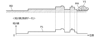
- FIGS. 4A and 4B are diagrams for explaining a method of deriving the correlation between the road surface roughness value and the lateral acceleration.
- the vehicle V1 shown in FIG. 4A is a dedicated vehicle equipped with a measuring device MA for measuring the roughness of the road surface.
- the measuring device MA measures the road surface roughness value of the road RD when the vehicle V1 is traveling on a predetermined road (measurement course or the like) RD.
- the characteristic P1 of FIG. 4A shows the road surface roughness value measured at this time.
- FIG. 4B shows how the vehicle 20 of FIG. 1 travels on the same road RD as that of FIG. 4A.
- the waveform P2 in FIG. 4B shows the lateral acceleration detected every 10 ms by the acceleration sensor 33 provided in the vehicle 20 while the vehicle 20 is traveling on a predetermined road RD.
- the vehicle 20 used for deriving the correlation will be referred to as a reference vehicle.
- the vehicle 20-1 is used as a reference vehicle.
- the road surface profile derivation unit 112 correlates the road surface roughness value and the lateral acceleration based on the road surface roughness value measured using the vehicle V1 and the lateral acceleration measured using the vehicle 20-1 which is a reference vehicle. The relationship is derived, and the information indicating the correlation is stored in the storage unit 120.
- deriving the correlation prepare a plurality of vehicles having the same vehicle type and grade as the vehicle 20-1, and use the lateral acceleration measured from each of the plurality of reference vehicles to derive the correlation. May be good. More specifically, statistical data (average value, etc.) of lateral acceleration measured from each of a plurality of reference vehicles may be used for deriving the correlation. Thereby, the correlation between the road surface roughness value and the lateral acceleration can be derived more accurately.
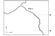
- FIG. 5A is a diagram showing an example of a map of the road on which the vehicle 20 travels.
- FIG. 5A shows a predetermined road (section of latitudes Y to Z of national highway X) to be derived from the road surface roughness value.
- the upward direction corresponds to the north direction
- the right direction corresponds to the east direction.
- the range to be derived from the road surface roughness value can be specified by the user as described later.
- the road to which the road surface roughness value is to be derived is a plurality of lanes on one side, the lane to which the road surface roughness value is to be derived is specified by the user.
- FIG. 1 shows a predetermined road (section of latitudes Y to Z of national highway X) to be derived from the road surface roughness value.
- the upward direction corresponds to the north direction
- the right direction corresponds to the east direction.
- the range to be derived from the road surface roughness value can be specified by the user as described later.
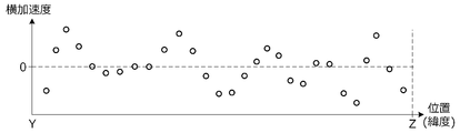
- 5B is a diagram showing an example of traveling information acquired by the road surface evaluation device 10 from the vehicle-mounted device 30 of the vehicle 20 traveling on the predetermined road of FIG. 5A (the section of latitude Y to Z of the national highway X).
- the horizontal axis in the figure is the position (latitude) in the traveling direction along the traveling lane of the vehicle 20, and the vertical axis is the lateral acceleration of the vehicle 20.
- FIG. 6 is a diagram showing an example of a road surface roughness value derived based on travel information acquired from an in-vehicle device 30 of a vehicle 20 traveling on the predetermined road.
- the characteristic P11 shown in FIG. 6 represents a road surface roughness value derived from the traveling information acquired from the in-vehicle device 30 of the vehicle 20-1.
- the characteristic P12 represents a road surface roughness value derived from the traveling information acquired from the in-vehicle device 30 of the vehicle 20-2.
- the characteristic P13 represents a road surface roughness value derived from the traveling information of the vehicle-mounted device 30 of the vehicle 20-3.
- the road surface roughness derived by the road surface profile deriving unit 112 is obtained.
- the value is different.
- the reason is that the parts that affect the movement of the vehicle, such as the suspension and tires mounted on each vehicle, differ depending on the vehicle type and grade.
- the impact absorption performance of suspensions and tires is usually higher as the grade is higher between the same vehicle models, and is higher as the ride quality is emphasized between different vehicle models.
- the characteristic P13 corresponding to the vehicle 20-3 which is a vehicle type in which the ride quality is emphasized, has a lower value than the characteristics P11 and P12 corresponding to the vehicles 20-1 and 20-2. ..
- the characteristic P12 corresponding to the vehicle 20-2 having a higher grade than the vehicle 20-1 has a lower value than the characteristic P11 corresponding to the vehicle 20-1.
- the vehicle type and grade of the vehicle 20 are specified based on the vehicle identification information of the vehicle 20 included in the traveling information. Further, the road surface roughness value derived from the driving information of each vehicle is corrected by using the correction coefficient corresponding to the specified vehicle type and grade.
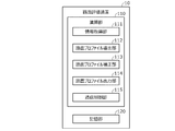
- FIG. 7 is a diagram showing an example of vehicle information.
- the vehicle information shown in FIG. 7 is created in advance and stored in the storage unit 120.
- the vehicle information includes information indicating the type of suspension and tire of the vehicle and a correction coefficient corresponding to the type in association with the vehicle type and grade of the vehicle.
- the road surface profile correction unit 113 previously drives vehicles 20 having different vehicle types and grades on a predetermined road (road RD in FIG. 4A).
- the road surface profile correction unit 113 determines the correction coefficient corresponding to the type of suspension and tire of each vehicle based on the ratio of the road surface roughness value of each vehicle derived based on the traveling information of each vehicle. In this way, the road surface profile correction unit 113 also functions as a correction coefficient determining unit.
- the road surface profile correction unit 113 stores information (vehicle information shown in FIG. 7) in which the determined correction coefficient is associated with the vehicle type and grade of the vehicle in the storage unit 120.
- the road surface profile correction unit 113 determines the correction coefficient of each vehicle, with the correction coefficient of the vehicle 20-1, which is the reference vehicle, being 1.0. For example, assuming that the vehicle type of vehicle 20-1 is "ABC" and the grade is "standard”, the suspension correction coefficient ⁇ 12 and the tire correction coefficient ⁇ 12 in FIG. 7 are 1.0, respectively.
- the same suspension and tires may be installed on all grades.
- the correction coefficient of the suspension of each grade may be the same value, or the correction coefficient of the tire of each grade may be the same value.
- the same suspension and tires may be installed between different vehicle models, and in such a case, the same correction coefficient is set between different vehicle models. For example, when the suspension "SS_13" is attached to a vehicle of the grade "high” of the vehicle type "XYZ", the correction coefficient of the suspension of the vehicle of the grade "high” of the vehicle type "XYZ" is the grade of the vehicle "ABC". It will be the same ⁇ 13 as the "low” vehicle.
- the road surface profile correction unit 113 corrects the road surface roughness value derived by the road surface profile derivation unit 112. More specifically, first, the road surface profile correction unit 113 determines the vehicle type and grade of the vehicle 20 that is the transmission source of the travel information based on the vehicle identification information of the vehicle 20 included in the travel information acquired by the information acquisition unit 111. Identify. The road surface profile correction unit 113 acquires vehicle information corresponding to the vehicle type and grade from the storage unit 120.
- the road surface profile correction unit 113 acquires the correction coefficient from the vehicle information of the vehicle 20. For example, when the vehicle type of the vehicle 20 is "ABC" and the grade is "low", ⁇ 13 is acquired as the suspension correction coefficient and ⁇ 13 is acquired as the tire correction coefficient.
- the road surface profile correction unit 113 corrects the road surface roughness value by multiplying the read correction coefficient by the road surface roughness value derived by the road surface profile derivation unit 112.
- the road surface profile correction unit 113 stores the corrected road surface roughness value (hereinafter, referred to as a corrected road surface roughness value) in the storage unit 120 in chronological order.
- the road surface profile output unit 114 outputs the corrected road surface roughness value stored in the storage unit 120 in time series in association with the road information acquired by the information acquisition unit 111.
- the communication control unit 115 controls a communication unit (not shown) to send / receive data to / from an external device or the like. More specifically, the communication control unit 115 transmits / receives data to / from a terminal such as an in-vehicle device 30 of the vehicle 20 or a road management company via the communication network 2. Further, the communication control unit 115 receives an output instruction of the road surface profile described later from a terminal of a road management company or the like via the communication network 2. Further, the communication control unit 115 acquires map information and the like from various servers connected to the communication network 2 periodically or at an arbitrary timing. Then, the communication control unit 115 stores the information acquired from various servers in the storage unit 120.
- FIG. 8 is a flowchart showing an example of processing executed by the calculation unit 110 (CPU) of the road surface evaluation device 10 according to a predetermined program. The process shown in this flowchart is repeated at a predetermined cycle while the road surface evaluation device 10 is activated.
- step S11 it is determined whether or not the traveling information is received from the in-vehicle device 30 of the vehicle 20. If denied in step S11, the process proceeds to step S16. If affirmed in step S11, the road surface roughness value is derived in step S12 based on the travel information received in step S11.
- step S13 the vehicle type and grade of the vehicle 20 are specified based on the vehicle identification information included in the travel information received in step S11, and the vehicle information corresponding to the vehicle type and grade is acquired from the storage unit 120.
- step S14 the road surface roughness value derived in step S12 is corrected by the correction coefficient included in the acquired vehicle information, that is, the correction coefficient corresponding to the vehicle type and grade of the vehicle 20.
- step S15 the corrected road surface roughness value (corrected road surface roughness value) is stored in the storage unit 120. At this time, the position information of the vehicle 20 included in the traveling information received in step S11 is stored in the storage unit 120 in association with the corrected road surface roughness value.
- step S16 it is determined whether or not the output instruction of the road surface profile has been input (received).
- the output instruction of the road surface profile is transmitted from a terminal of a user (road management company, etc.) to the road surface evaluation device 10 via the communication network 2, for example.
- the output instruction of the road surface profile may be input to the road surface evaluation device 10 via an operation unit (not shown) included in the road surface evaluation device 10.
- the output instruction of the road surface profile includes section information that can specify the section of the road to be output.
- the section information is information indicating the name and section of the road to be output, such as "road: national highway X, section: latitude Y to Z". If the road has multiple lanes on each side, such as two lanes on each side, the section information includes information on the lane to be output, such as "road: national highway X, lane: right end, section: latitude Y to Z". May be included.
- information other than latitude may be used to specify the section to be output. For example, longitude may be used instead of latitude, or longitude may be used in addition to latitude. Further, the distance from the starting point (for example, the point at the longitude Y of the national highway X) may be used.
- step S16 If denied in step S16, the process ends. If affirmed in step S16, the map information is read from the storage unit 120 in step S17, and the road information included in the map information is acquired. In step S18, the corrected road surface roughness value of the vehicle 20 is acquired from the storage unit 120. More specifically, based on the section information included in the output instruction of the road surface profile and the road information acquired in step S17, the corrected road surface roughness value of the section targeted for output stored in the storage unit 120 is stored. Obtained from the storage unit 120. At this time, the position information of the vehicle 20 stored in the storage unit 120 in association with the corrected road surface roughness value is also acquired.
- step S19 the corrected road surface roughness value acquired in step S18 is output in association with the road information acquired in step S17. More specifically, based on the road information acquired in step S17 and the position information of the vehicle 20 associated with the corrected road surface roughness value, each position of the section targeted for output is acquired in step S18. The corrected road surface roughness value is associated and output.
- the information output at this time is referred to as road surface profile information.
- the road surface profile information is output to a terminal of a transmission source of an output instruction of the road surface profile or a terminal of a predetermined output destination via the communication network 2.
- the road surface profile information is information that can be displayed on a display device such as a display, and the user can confirm or evaluate the road surface profile by displaying the road surface profile information on the display of the user's terminal. Even if it is denied in step S16, if the corrected road surface roughness value that has not been output among the corrected road surface roughness values of the vehicle 20 stored in the storage unit 120 is accumulated in a predetermined amount or more. , You may proceed to step S17. Even if the affirmation is made in step S16, if the corrected road surface roughness value of the vehicle 20 stored in the storage unit 120 but not output is less than a predetermined amount, the process is performed. May be terminated.
- information for notifying that the corrected road surface roughness value that has not been output is less than a predetermined amount is provided to the terminal of the transmission source of the road surface profile output instruction, etc. It may be output to.
- the road surface evaluation device 10 acquires driving information including information indicating the movement of the moving vehicle 20 and position information of the vehicle 20, acquires map information including information on the road on which the vehicle travels, and vehicles. Based on the information acquisition unit 111 that acquires vehicle information including the unique information of 20 and the travel information acquired by the information acquisition unit 111, a roughness value indicating the roughness of the road surface on which the vehicle 20 travels is derived.
- the road surface profile derivation unit 112, the road surface profile correction unit 113 that corrects the roughness value of the road surface derived by the road surface profile derivation unit 112 based on the vehicle information acquired by the information acquisition unit 111, and the road surface profile correction unit 113. It has an output unit that outputs the road surface roughness value corrected by the above method in association with the road information acquired by the information acquisition unit 111 (FIG. 3).
- the road surface evaluation device 10 further includes a storage unit 120 for storing vehicle information.
- the information acquisition unit 111 acquires vehicle information from the storage unit 120 based on the vehicle identification information included in the acquired travel information. As a result, the vehicle information of the moving vehicle 20 can be acquired in real time, and the road surface roughness value can be corrected in real time.
- the unique information of the vehicle 20 includes information regarding the type and grade of the vehicle 20.
- the correction can be performed according to the type and grade of the vehicle 20, and the road surface roughness can be corrected regardless of the type and grade of the vehicle 20.
- the roughness value can be corrected with high accuracy.
- the grade information includes information on at least one type of vehicle suspension and tire.
- the road surface profile correction unit 113 has a road surface profile derivation unit 112 based on travel information acquired from each vehicle when a plurality of vehicles are previously driven on a predetermined road (road RD shown in FIG. 4A). To determine the correction coefficient for correcting the roughness value of the road surface derived by.
- the vehicle information includes a correction coefficient in association with the unique information of the vehicle 20.
- the road surface profile correction unit 113 corrects the roughness value of the road surface derived by the road surface profile derivation unit 112 by using the correction coefficient included in the vehicle information acquired by the information acquisition unit 111. Thereby, when the road surface roughness value derived from the traveling information of the vehicle is corrected, the correction can be performed for each vehicle by using the correction coefficient corresponding to the vehicle. Therefore, even when there are a plurality of traveling vehicles, the road surface roughness value derived from the traveling information of each vehicle can be corrected with high accuracy.
- the road surface evaluation device 10 of the present embodiment can also be used as a road surface evaluation method.
- the road surface evaluation method there is a step of acquiring driving information including information indicating the movement of the moving vehicle 20 and position information of the vehicle 20, and a step of acquiring map information including information on the road on which the vehicle 20 is traveling.
- a computer executes a step of correcting the derived road surface roughness value based on the vehicle information and a step of outputting the corrected road surface roughness value in association with the acquired road information. Including that. Thereby, a road surface profile that can be sufficiently evaluated can be derived regardless of the type of the vehicle 20 traveling on the road.
- the information acquisition unit 111 acquires the lateral acceleration of the vehicle 20 detected by the acceleration sensor 33 as the travel information acquisition unit as information indicating the motion of the vehicle 20.
- the information indicating the motion is not limited to the lateral acceleration of the vehicle 20 detected by the acceleration sensor 33. That is, any configuration of the traveling information acquisition unit may be used as long as the information indicating the motion of the vehicle 20 is acquired.
- the vehicle speed of the vehicle 20 detected by the vehicle speed sensor 35 and the steering angle of the vehicle 20 detected by the steering angle sensor 34 may be acquired as information indicating motion.
- the road surface profile derivation unit 112 derives the road surface roughness value based on the lateral acceleration of the vehicle 20 detected by the acceleration sensor 33 as the roughness value derivation unit.
- the roughness value deriving unit may be used as long as the road surface roughness value of the road on which the vehicle 20 travels is derived.
- the information acquisition unit 111 acquires map information including information on the road on which the vehicle 20 travels as a map information acquisition unit from the storage unit 120, but the map information can be obtained from an external server or the like. It may be stored in an external storage device. That is, any configuration of the map information acquisition unit may be used as long as it acquires map information including information on the road on which the vehicle 20 travels.
- the information acquisition unit 111 acquires vehicle information including the unique information of the vehicle 20 from the storage unit 120 as the vehicle information acquisition unit, but the vehicle information is stored in an external server or an external storage unit. It may be stored in the device. That is, any configuration of the vehicle information acquisition unit may be used as long as it acquires vehicle information including information on the road on which the vehicle 20 travels.
- the road surface profile correction unit 113 uses the correction coefficient as the roughness value correction unit to correct the road surface roughness value derived by the road surface profile derivation unit 112.
- the roughness value correction unit may correct the road surface roughness value by using a correction formula or a table instead of the correction coefficient. That is, any configuration of the roughness value correction unit may be used as long as the road surface roughness value is corrected.
- the road surface profile correction unit 113 corrects the road surface roughness value derived by the road surface profile derivation unit 112 based on the vehicle speed detected by the vehicle speed sensor 35 and the steering angle detected by the steering angle sensor 34. You may do it.
- the acceleration sensor 33 detects not only the lateral acceleration generated by the unevenness of the road surface but also the lateral acceleration generated by the centrifugal force generated according to the speed and steering angle of the vehicle 20. .. Therefore, in such a case, the road surface profile correction unit 113 removes the component based on the lateral acceleration due to the centrifugal force from the road surface roughness value derived based on the lateral acceleration detected by the acceleration sensor 33.
- the road surface roughness value may be corrected. As a result, it is possible to accurately derive the road surface roughness value of a road other than a straight line.
- the road surface profile correction unit 113 may correct the road surface roughness value derived by the road surface profile derivation unit 112 based on the vehicle speed detected by the vehicle speed sensor 35. Even when the vehicle 20 travels on the same road, the lateral acceleration of the vehicle 20 detected by the acceleration sensor 33 changes according to the vehicle speed during traveling. More specifically, the faster the vehicle speed during traveling, the more difficult it is for the tires of the vehicle 20 to follow the road surface, and the smaller the lateral acceleration detected by the acceleration sensor 33.
- the road surface profile correction unit 113 may correct the road surface roughness value derived by the road surface profile derivation unit 112 by using the correction coefficient included in the vehicle information and the correction coefficient according to the vehicle speed.
- the road surface profile correction unit 113 previously drives the vehicle 20 at different vehicle speeds on a predetermined road and measures the difference in the road surface roughness value caused by the difference in the road surface followability of the vehicle 20.
- the road surface profile correction unit 113 determines a correction coefficient according to the vehicle speed of the vehicle 20 based on the measurement result, and stores the correction coefficient in the storage unit 120. With this configuration, the road surface roughness value can be accurately corrected regardless of the vehicle speed of the vehicle 20.
- the road surface profile output unit 114 outputs the road surface profile information to the user's terminal as an output unit, but the output unit outputs the road surface profile information to the map information stored in the storage unit 120.
- the road surface profile information may be output to the storage unit 120 so as to be mapped. That is, any configuration of the output unit may be used as long as the road surface profile information is output.
- the road surface roughness value is represented by IRI
- the road surface roughness value may be represented by another index.
- the road surface profile deriving unit 112 may derive the road surface roughness value represented by the index. ..
- the vehicle information may also include vehicle maintenance information, including information on vehicle suspension or tire replacement. More specifically, when the suspension or tire of the vehicle is replaced, the road surface profile correction unit 113 is newly attached to the vehicle in association with the vehicle identification information of the vehicle in which the suspension or tire is replaced.
- the vehicle information may include information indicating the type of suspension or tire and a correction coefficient corresponding to the type. As a result, even when the suspension or tire of the vehicle is replaced, the road surface roughness value derived from the traveling information of the vehicle can be corrected with high accuracy.
- the road surface profile correction unit 113 puts the vehicle with the replaced suspension or tire on a predetermined road (for example, FIG. 4A). Drive on the road RD).
- the road surface profile correction unit 113 determines a correction coefficient corresponding to the type of newly mounted suspension and tire based on the road surface roughness value derived from the traveling information of the vehicle.
- the predetermined road used when determining the correction coefficient is not limited to the measurement course. If the road surface roughness value has already been derived and the reliability of the road surface roughness value is high (greater than or equal to a predetermined value), even if a general road is used when determining the correction coefficient. good.
- the road surface profile correction unit 113 may correct the road surface roughness value derived by the road surface profile derivation unit 112 based on the state of the suspension and the tire of the vehicle 20.
- the condition of the suspension and tires changes depending on the period of use and the like. Normally, the longer the suspension and tires are used, the lower the impact absorption performance is, and the impact and vibration due to the unevenness of the road surface are easily transmitted to the vehicle.
- the period of use of the suspension and tires of the vehicle 20 can be predicted to some extent from the year of manufacture of the vehicle 20 and the time when the suspension and tires are replaced. Therefore, the road surface profile correction unit 113 specifies the year of manufacture of the vehicle 20 from the vehicle identification information of the vehicle 20.
- the road surface profile correction unit 113 specifies the suspension and tire replacement time from the maintenance information.
- the road surface profile correction unit 113 uses the correction coefficient included in the vehicle information and the correction coefficient according to the year of manufacture of the vehicle 20 and the replacement time of the suspension and tires, and the road surface roughness derived by the road surface profile extraction unit 112.
- the value may be corrected.
- the correction coefficient according to the year of manufacture of the vehicle 20 and the time of replacement of the suspension and tires is set to a larger value as the difference between the year of manufacture and the time of replacement and the present time increases.
Landscapes
- Engineering & Computer Science (AREA)
- Physics & Mathematics (AREA)
- General Physics & Mathematics (AREA)
- Automation & Control Theory (AREA)
- Architecture (AREA)
- Civil Engineering (AREA)
- Structural Engineering (AREA)
- Transportation (AREA)
- Mechanical Engineering (AREA)
- Mathematical Physics (AREA)
- Human Computer Interaction (AREA)
- Road Repair (AREA)
- Traffic Control Systems (AREA)
- Length Measuring Devices With Unspecified Measuring Means (AREA)
Priority Applications (2)
| Application Number | Priority Date | Filing Date | Title |
|---|---|---|---|
| JP2022526927A JP7469468B2 (ja) | 2020-05-28 | 2021-05-19 | 路面評価装置および路面評価方法 |
| US17/927,206 US12421676B2 (en) | 2020-05-28 | 2021-05-19 | Road surface evaluation apparatus and road surface evaluation method |
Applications Claiming Priority (2)
| Application Number | Priority Date | Filing Date | Title |
|---|---|---|---|
| JP2020093108 | 2020-05-28 | ||
| JP2020-093108 | 2020-05-28 |
Publications (1)
| Publication Number | Publication Date |
|---|---|
| WO2021241350A1 true WO2021241350A1 (ja) | 2021-12-02 |
Family
ID=78744587
Family Applications (1)
| Application Number | Title | Priority Date | Filing Date |
|---|---|---|---|
| PCT/JP2021/018956 Ceased WO2021241350A1 (ja) | 2020-05-28 | 2021-05-19 | 路面評価装置および路面評価方法 |
Country Status (3)
| Country | Link |
|---|---|
| US (1) | US12421676B2 (https=) |
| JP (1) | JP7469468B2 (https=) |
| WO (1) | WO2021241350A1 (https=) |
Cited By (1)
| Publication number | Priority date | Publication date | Assignee | Title |
|---|---|---|---|---|
| AU2024200931B2 (en) * | 2023-02-20 | 2025-08-14 | Komatsu Ltd. | Road surface condition obtaining system |
Families Citing this family (2)
| Publication number | Priority date | Publication date | Assignee | Title |
|---|---|---|---|---|
| CN115803794B (zh) * | 2020-07-14 | 2025-02-18 | 本田技研工业株式会社 | 路面评价装置以及路面评价方法 |
| US12158354B2 (en) * | 2021-12-14 | 2024-12-03 | GM Global Technology Operations LLC | Connected vehicle-based road surface quality determination |
Citations (2)
| Publication number | Priority date | Publication date | Assignee | Title |
|---|---|---|---|---|
| JP2015184816A (ja) * | 2014-03-20 | 2015-10-22 | Jx日鉱日石エネルギー株式会社 | 評価サーバ |
| WO2018025341A1 (ja) * | 2016-08-03 | 2018-02-08 | 三菱電機株式会社 | 道路状態診断システム、診断用情報生成装置及び診断用情報生成方法 |
Family Cites Families (3)
| Publication number | Priority date | Publication date | Assignee | Title |
|---|---|---|---|---|
| JP2002012138A (ja) | 2000-06-29 | 2002-01-15 | Toyota Motor Corp | 路面の凹凸状態検出装置 |
| JP5837341B2 (ja) * | 2011-06-24 | 2015-12-24 | 株式会社ブリヂストン | 路面状態判定方法とその装置 |
| FR3006241B1 (fr) * | 2013-06-04 | 2015-05-15 | Renault Sa | Procede de detection et d'indication d'usure dissymetrique d'un pneumatique de vehicule |
-
2021
- 2021-05-19 US US17/927,206 patent/US12421676B2/en active Active
- 2021-05-19 JP JP2022526927A patent/JP7469468B2/ja active Active
- 2021-05-19 WO PCT/JP2021/018956 patent/WO2021241350A1/ja not_active Ceased
Patent Citations (2)
| Publication number | Priority date | Publication date | Assignee | Title |
|---|---|---|---|---|
| JP2015184816A (ja) * | 2014-03-20 | 2015-10-22 | Jx日鉱日石エネルギー株式会社 | 評価サーバ |
| WO2018025341A1 (ja) * | 2016-08-03 | 2018-02-08 | 三菱電機株式会社 | 道路状態診断システム、診断用情報生成装置及び診断用情報生成方法 |
Cited By (1)
| Publication number | Priority date | Publication date | Assignee | Title |
|---|---|---|---|---|
| AU2024200931B2 (en) * | 2023-02-20 | 2025-08-14 | Komatsu Ltd. | Road surface condition obtaining system |
Also Published As
| Publication number | Publication date |
|---|---|
| US12421676B2 (en) | 2025-09-23 |
| JPWO2021241350A1 (https=) | 2021-12-02 |
| JP7469468B2 (ja) | 2024-04-16 |
| US20230243113A1 (en) | 2023-08-03 |
Similar Documents
| Publication | Publication Date | Title |
|---|---|---|
| WO2021241350A1 (ja) | 路面評価装置および路面評価方法 | |
| CN105473983A (zh) | 路面上的短期不平度的检测 | |
| CN106842269A (zh) | 定位方法及系统 | |
| US11117589B2 (en) | System and method for determining roadway bank angle | |
| US11530932B2 (en) | Method of characterizing the condition of a road | |
| CN104864878A (zh) | 基于电子地图的路况物理信息绘制及查询方法 | |
| US12157486B2 (en) | Road surface evaluation apparatus | |
| JP7368628B2 (ja) | 路面評価装置および路面評価方法 | |
| CN110264741B (zh) | 基于运动传感器的路况检测方法、装置、设备及介质 | |
| JP7273943B1 (ja) | 路面評価装置 | |
| JP7430272B2 (ja) | 路面評価装置および路面評価方法 | |
| JP2018205970A (ja) | 路面情報収集システム | |
| CN110211384B (zh) | 基于车车通讯的路况实现方法 | |
| US20250146238A1 (en) | Road surface evaluation apparatus | |
| JP7664432B2 (ja) | 路面評価装置 | |
| US12516953B1 (en) | Road surface evaluation apparatus and road surface evaluation method | |
| JP2018205972A (ja) | 路面情報収集システム | |
| JP7625630B2 (ja) | 路面評価装置 | |
| JP7625629B2 (ja) | 路面評価装置 | |
| JP7657851B2 (ja) | 路面評価装置 | |
| JP2025034699A (ja) | 路面評価装置 |
Legal Events
| Date | Code | Title | Description |
|---|---|---|---|
| 121 | Ep: the epo has been informed by wipo that ep was designated in this application |
Ref document number: 21811809 Country of ref document: EP Kind code of ref document: A1 |
|
| ENP | Entry into the national phase |
Ref document number: 2022526927 Country of ref document: JP Kind code of ref document: A |
|
| NENP | Non-entry into the national phase |
Ref country code: DE |
|
| 122 | Ep: pct application non-entry in european phase |
Ref document number: 21811809 Country of ref document: EP Kind code of ref document: A1 |
|
| WWG | Wipo information: grant in national office |
Ref document number: 17927206 Country of ref document: US |