WO2021240950A1 - 分離装置及び分離システム - Google Patents
分離装置及び分離システム Download PDFInfo
- Publication number
- WO2021240950A1 WO2021240950A1 PCT/JP2021/009816 JP2021009816W WO2021240950A1 WO 2021240950 A1 WO2021240950 A1 WO 2021240950A1 JP 2021009816 W JP2021009816 W JP 2021009816W WO 2021240950 A1 WO2021240950 A1 WO 2021240950A1
- Authority
- WO
- WIPO (PCT)
- Prior art keywords
- casing
- rotating body
- axial direction
- separation device
- separation
- Prior art date
- Legal status (The legal status is an assumption and is not a legal conclusion. Google has not performed a legal analysis and makes no representation as to the accuracy of the status listed.)
- Ceased
Links
Images




Classifications
-
- B—PERFORMING OPERATIONS; TRANSPORTING
- B01—PHYSICAL OR CHEMICAL PROCESSES OR APPARATUS IN GENERAL
- B01D—SEPARATION
- B01D45/00—Separating dispersed particles from gases or vapours by gravity, inertia, or centrifugal forces
- B01D45/12—Separating dispersed particles from gases or vapours by gravity, inertia, or centrifugal forces by centrifugal forces
- B01D45/14—Separating dispersed particles from gases or vapours by gravity, inertia, or centrifugal forces by centrifugal forces generated by rotating vanes, discs, drums or brushes
-
- B—PERFORMING OPERATIONS; TRANSPORTING
- B04—CENTRIFUGAL APPARATUS OR MACHINES FOR CARRYING-OUT PHYSICAL OR CHEMICAL PROCESSES
- B04B—CENTRIFUGES
- B04B5/00—Other centrifuges
- B04B5/12—Centrifuges in which rotors other than bowls generate centrifugal effects in stationary containers
-
- B—PERFORMING OPERATIONS; TRANSPORTING
- B04—CENTRIFUGAL APPARATUS OR MACHINES FOR CARRYING-OUT PHYSICAL OR CHEMICAL PROCESSES
- B04B—CENTRIFUGES
- B04B7/00—Elements of centrifuges
- B04B7/02—Casings; Lids
-
- B—PERFORMING OPERATIONS; TRANSPORTING
- B04—CENTRIFUGAL APPARATUS OR MACHINES FOR CARRYING-OUT PHYSICAL OR CHEMICAL PROCESSES
- B04B—CENTRIFUGES
- B04B9/00—Drives specially designed for centrifuges; Arrangement or disposition of transmission gearing; Suspending or balancing rotary bowls
- B04B9/02—Electric motor drives
Definitions
- the present disclosure relates to a separation device and a separation system, and more particularly to a separation device for separating a solid contained in a gas from a gas, and a separation system including the separation device.
- a centrifuge device including a chamber having a cylindrical confinement wall and a driving rotor having a plurality of blades fixed to a shaft is known (Patent Document 1).
- the cylindrical confinement wall surrounds the shaft and is arranged coaxially with the shaft.
- the blade is located between the shaft and the cylindrical confinement wall and is connected to the shaft.
- the cylindrical confinement wall has an inlet opening (inlet), an outlet opening (outlet), and a removal opening (outlet).
- the removal opening is provided closer to the outlet opening than to the position closer to the inlet opening.
- the separation device it is desired to improve the separation performance of separating the solid contained in the gas from the gas.
- An object of the present disclosure is to provide a separation device and a separation system capable of improving the separation performance of separating a solid contained in a gas from the gas.
- the separation device includes a casing, a rotating body, and blades.
- the casing has a gas inlet, a gas outlet, and a solid outlet.
- the rotating body is arranged inside the casing.
- the rotating body can rotate about a rotation center axis along the axial direction of the casing.
- the blades are arranged between the casing and the rotating body. The blade rotates together with the rotating body.
- the blade has a first end on the gas inlet side and a second end on the gas outlet side.
- the casing has a space on the solid discharge port side of the second end of the blade in the axial direction.
- the separation device further comprises a separation wall. The separation wall separates the space into a first region on the inner side and a second region on the outer side when viewed from the axial direction of the casing.
- the separation system includes the separation device and a drive device.
- the drive device rotationally drives the rotating body.
- FIG. 1 is a perspective view of the separation device according to the embodiment.
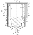
- FIG. 2 is a cross-sectional view including a rotation center axis in the same separation device with an outer cover attached.
- FIG. 3 is a cross-sectional view corresponding to the cross section taken along line III-III of FIG. 2 with respect to the separation device of the same.
- FIG. 4 is a cross-sectional view corresponding to the IV-IV line cross section of FIG. 2 with respect to the separation device of the same.
- FIG. 5 is a schematic configuration diagram of a separation system including the same separation device.
- FIG. 6 is a diagram showing a simulation result of the pressure distribution inside the casing in the same separation device.
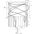
- FIG. 7 is a diagram showing a simulation result of a particle trajectory in the same separation device.
- FIG. 1 is a perspective view of the separation device according to the embodiment.
- FIG. 2 is a cross-sectional view including a rotation center axis in the same separation device with an outer cover attached.
- FIG. 8 is a diagram showing a simulation result of the trajectory of another particle in the same separation device.
- FIG. 9 is a cross-sectional view including a rotation center axis in a state where an outer cover is attached in the separation device according to the first modification of the embodiment.
- each figure described in the following embodiment is a schematic view, and the ratio of the size and the thickness of each component in the figure does not necessarily reflect the actual dimensional ratio. ..
- the separation device 1 is provided, for example, on the upstream side of an air conditioner having a ventilation function, and separates solids in air (gas).
- the separation device 1 is installed, for example, on the roof of a facility (house or the like) having a flat roof, or on the ground.
- the air conditioning equipment is, for example, a blower that blows air from the upstream side to the downstream side.
- the blower is, for example, an electric fan.
- the air conditioning equipment is not limited to the blower, and may be, for example, an air conditioning system including a ventilation device, an air conditioner, an air supply cabinet fan, a blower and a heat exchanger.
- the flow rate of the air flowing through the separation device 1 by the air conditioning equipment is, for example, 50 m 3 / h to 500 m 3 / h.
- the amount of air flowing out from the separating device 1 to the air conditioning equipment side is substantially the same as the flow rate of air flowing through the air conditioning equipment.
- the separating device 1 includes a casing 2, a rotating body 3, and blades 4. Further, as shown in FIG. 5, the separation system 10 includes a separation device 1 and a drive device 11.
- the casing 2 has a gas inlet 21, a gas outlet 22, and a solid discharge port 23.
- the rotating body 3 is arranged inside the casing 2.
- the rotating body 3 can rotate about the rotation center axis 30 along the axial direction D1 of the casing 2.
- the blade 4 is arranged between the casing 2 and the rotating body 3.
- the blade 4 rotates together with the rotating body 3.
- the blade 4 has a first end 41 on the gas inlet 21 side and a second end 42 on the gas outlet 22 side.
- the casing 2 has a space 25 on the solid discharge port 23 side of the second end 42 of the blade 4 in the axial direction D1 of the casing 2.
- the solid discharge port 23 is, for example, a hole for discharging the solid contained in the air to the outside of the casing 2.
- the solid discharge port 23 connects the inner space of the casing 2 and the outer space of the casing 2. In other words, the solid discharge port 23 communicates the inside and outside of the casing 2.
- the separating device 1 generates an air flow swirling in the casing 2 in the casing 2 when the rotating body 3 rotates. In the separating device 1, a part of the flow path from the gas inlet 21 to the gas outlet 22 is formed between the casing 2 and the rotating body 3.
- the separation device 1 further includes a separation wall 5.
- the separation wall 5 is arranged in the space 25.
- the separation wall 5 separates the space 25 into a first region R1 on the inner side and a second region R2 on the outer side when viewed from the axial direction D1 of the casing 2.
- the separation device 1 can flow the air flowing into the casing 2 from the upstream side to the downstream side while spirally rotating around the rotating body 3.
- the "upstream side” here means the upstream side (primary side) when viewed in the direction of air flow.
- the “downstream side” means the downstream side (secondary side) when viewed in the direction of air flow.
- the separation device 1 is used, for example, in a state where the gas outlet 22 is located above the gas inlet 21. In this case, in the separation device 1, the air flowing into the flow path from the gas inlet 21 of the casing 2 can be moved while spirally rotating around the rotating body 3 and flowed to the gas outlet 22.
- the separation device 1 has the above-mentioned solid discharge port 23 in order to discharge the solid contained in the air flowing into the casing 2 to the outside of the casing 2. As a result, at least a part of the solid contained in the air flowing into the casing 2 from the gas inlet 21 of the casing 2 is discharged to the outside of the casing 2 from the solid discharge port 23 while passing through the flow path. NS.
- the separation system 10 includes a drive device 11 in addition to the separation device 1.
- the drive device 11 rotationally drives the rotating body 3. That is, the drive device 11 rotates the rotating body 3 around the rotation center axis 30.
- the drive device 11 includes, for example, a motor.
- Examples of the solid in the air include fine particles, dust and the like.
- Examples of the fine particles include particulate matter and the like.
- Particulate matter includes primary particles that are directly released into the air as fine particles, and secondary particles that are released into the air as gas and are produced as fine particles in the air.
- Examples of the primary particles include soil particles (yellow sand and the like), dust, plant particles (pollen and the like), animal particles (mold spores and the like), soot and the like.
- PM1.0, PM2.5 fine particulate matter
- PM10 fine particulate matter
- SPM suspended particulate matter
- PM1.0 is fine particles that pass through a sizing device having a particle size of 1.0 ⁇ m and a collection efficiency of 50%.
- PM2.5 is fine particles that pass through a sizing device having a particle size of 2.5 ⁇ m and a collection efficiency of 50%.
- PM10 is a fine particle that passes through a sizing device having a particle size of 10 ⁇ m and a collection efficiency of 50%.
- SPM is fine particles that pass through a sizing device having a particle size of 10 ⁇ m and a collection efficiency of 100%, which corresponds to PM6.5-7.0 and is slightly smaller than PM10.
- the separation device 1 includes a casing 2, a rotating body 3, blades 4, and a separation wall 5. As shown in FIGS. 1 and 2, the separation device 1 further includes an outflow cylinder portion 6, a rectifying structure 8, and a structure 9. Further, the separation system 10 includes a separation device 1, a drive device 11, and a control device 12.
- the material of the casing 2 is, for example, a metal, but the material is not limited to this, and a resin (for example, ABS resin) may be used. Further, the casing 2 may include a metal portion formed of metal and a resin portion formed of resin.
- the casing 2 includes a tubular portion 20 having a first end 201 and a second end 202, and a bottom portion 24 closing the opening of the second end 202 of the tubular portion 20.
- the casing 2 has a bottomed cylindrical shape.
- the axial direction D1 of the casing 2 is a direction along the central axis of the tubular portion 20.
- the tubular portion 20 has a small diameter portion 211, an enlarged diameter portion 212, and a large diameter portion 213.
- the small diameter portion 211, the enlarged diameter portion 212, and the large diameter portion 213 are arranged in this order in the axial direction D1 of the casing 2.
- the small diameter portion 211 has a gas inlet 21, and the large diameter portion 213 has a gas outlet 22 and a solid discharge port 23.
- the gas inlet 21, the gas outlet 22, and the solid outlet 23 are open to the side of the casing 2.
- the gas inlet 21, the solid discharge port 23, and the gas outlet 22 are arranged in this order.
- a part (downstream end) of the solid discharge port 23 overlaps with the gas outlet 22 in one surface orthogonal to the axial direction D1 of the casing 2 (see FIG. 4).
- the small diameter portion 211 has a gas inflow port 21.
- the small diameter portion 211 has a cylindrical shape with both sides open.
- the gas inflow port 21 is formed on the side surface of the small diameter portion 211.
- the gas inflow port 21 is formed in the small diameter portion 211 near the bottom portion 2111 of the small diameter portion 211.
- Casing 2 has a plurality of gas inlets 21.
- Each gas inlet 21 has a substantially 1/4 arc shape.
- the large diameter portion 213 has a cylindrical shape with both ends open and surrounds the rotating body 3.
- the length of the large diameter portion 213 is longer than the length of the rotating body 3.
- the inner diameter and the outer diameter of the large diameter portion 213 are constant over the total length in the axial direction of the large diameter portion 213.
- the outer diameter and inner diameter of the large diameter portion 213 are larger than the outer diameter and inner diameter of the small diameter portion 211, respectively.
- the solid discharge port 23 is formed on the outer peripheral surface 27 of the casing 2 (here, the outer peripheral surface of the large diameter portion 213).
- the solid discharge port 23 has a slit shape extending along the axial direction of the large diameter portion 213 (axial direction D1 of the casing 2).
- the solid discharge port 23 is formed in a portion corresponding to the space 25 in the large diameter portion 213.
- the solid discharge port 23 is separated from the gas inflow port 21 in the axial direction D1 of the casing 2, and the inside and outside of the cylinder portion 20 (large diameter portion 213) between the first end 201 and the second end 202 of the cylinder portion 20. Communicate.
- the solid discharge port 23 extends in a direction along a tangential direction of the inner peripheral surface 26 (inner peripheral surface of the large diameter portion 213) of the casing 2 when viewed from the axial direction D1 of the casing 2.
- the tangential direction is a direction along the rotation direction A1 (see FIGS. 3 and 4) of the rotating body 3.
- the inner surface of the solid discharge port 23 is a rear inner surface 231 located rearward and a front inner surface 232 located forward in the direction along the rotation direction A1 of the rotating body 3. Has.
- the rear inner surface 231 is connected to the inner peripheral surface 26 (inner peripheral surface of the large diameter portion 213) of the casing 2.
- the outer end P12 on the side farther from the rotating body 3 is located in front of the inner end P11 on the side closer to the rotating body 3 in the rotation direction A1.
- the rear inner surface 231 extends in the tangential direction of the inner peripheral surface 26 at the inner end P11 of the rear inner surface 231.
- the solid discharge port 23 in the casing 2 has a rear inner surface 231 and a front inner surface 232 located in the rear and front, respectively, in the rotation direction A1 of the rotating body 3.
- the front inner surface 232 is substantially parallel to the rear inner surface 231.
- the casing 2 (large diameter portion 213) has a plurality of (two in the illustrated example) solid discharge ports 23.
- the two solid discharge ports 23 are opposite to each other on the outer peripheral surface of the large diameter portion 213.
- solids passing near the inner peripheral surface 26 of the casing 2 here, the inner peripheral surface of the large diameter portion 213) can be discharged from each solid discharge port 23.
- the separation device 1 is provided with a guide wall 28.
- the guide wall 28 is provided in the casing 2.
- the separation device 1 includes a plurality of (two in the illustrated example) guide walls 28.
- the two guide walls 28 have a one-to-one correspondence with the two solid outlets 23.
- the guide wall 28 extends from the inner peripheral surface 26 of the casing 2 to the inside of the casing 2.
- One surface of the guide wall 28 is flush with the front inner surface 232 of the solid discharge port 23.
- the guide wall 28 is formed from the inner peripheral surface 26 of the casing 2 to the front inner surface 232 of the solid discharge port 23 along the one center line of the casing 2 (one center line of the large diameter portion 213; the alternate long and short dash line in FIGS. 3 and 4). (Indicated by).
- the one center line is orthogonal to the rotation center axis 30 of the rotating body 3 and is orthogonal to the one tangential direction.
- the large diameter portion 213 has a gas outlet 22.
- the gas outlet 22 is formed on the side surface of the large diameter portion 213.
- the gas outlet 22 is formed in the large diameter portion 213 near the bottom portion 24.
- the gas outlet 22 is separated from the gas inlet 21 in the axial direction D1 of the casing 2, and the inside and outside of the cylinder 20 (large diameter portion 213) between the first end 201 and the second end 202 of the cylinder 20. Communicate.
- the gas outlet 22 is adjacent to the solid outlet 23 of one of the two solid outlets 23.
- the gas outlet 22 is in front of the adjacent solid discharge port 23 in the rotation direction A1 (see FIGS. 3 and 4) of the rotating body 3.
- the enlarged diameter portion 212 connects the small diameter portion 211 and the large diameter portion 213.
- the enlarged diameter portion 212 has a first end on the small diameter portion 211 side and a second end on the large diameter portion 213 side. The first end of the enlarged diameter portion 212 is connected to the small diameter portion 211.
- the inner space of the enlarged diameter portion 212 is connected to the inner space of the small diameter portion 211.
- the second end of the enlarged diameter portion 212 is connected to the large diameter portion 213.
- the inner space of the enlarged diameter portion 212 is connected to the inner space of the large diameter portion 213.
- the enlarged diameter portion 212 has a tapered cylindrical shape in which the outer diameter and the inner diameter gradually increase as the casing 2 moves away from the small diameter portion 211 and approaches the large diameter portion 213 in the axial direction D1 of the casing 2.
- the outer diameter and inner diameter of the enlarged diameter portion 212 are the same as the outer diameter and inner diameter of the small diameter portion 211 at the end of the casing 2 on the small diameter portion 211 side in the axial direction D1, respectively.
- the outer diameter and inner diameter of the enlarged diameter portion 212 are the same as the outer diameter and inner diameter of the large diameter portion 213 at the end of the casing 2 on the large diameter portion 213 side in the axial direction D1, respectively. That is, in the diameter-expanded portion 212, the opening area gradually increases as the distance from the gas inlet 21 in the axial direction D1 of the casing 2 increases.
- the outflow tube portion 6 is connected to the casing 2.
- the outflow tube portion 6 is connected to the gas outlet 22 on the outer peripheral surface 27 of the casing 2 (large diameter portion 213), for example.
- the inner space 60 of the outflow cylinder portion 6 is connected to the inner space of the cylinder portion 20 (the inner space of the large diameter portion 213) through the gas outlet 22.
- the outflow tube portion 6 is a duct for supplying the gas from which the solid is separated to the outside of the casing 2.
- the outflow cylinder portion 6 is viewed from the axial direction D1 of the casing 2 in the radial direction of the casing 2 at the position where the gas outlet 22 is located and in the direction intersecting the axial direction D1 of the casing 2 from the outer peripheral surface 27 of the casing 2. It is extended.
- the outflow cylinder portion 6 has a square cylinder shape. In the outflow tube portion 6, the opening on the side opposite to the gas outlet 22 side is square, but is not limited to this.
- the rotating body 3 is arranged coaxially with the casing 2 inside the casing 2. "Arranged coaxially with the casing 2" means that the rotating body 3 uses the rotating central axis 30 (see FIG. 2) of the rotating body 3 as the central axis 29 of the casing 2 (central axis of the large diameter portion 213). It means that they are arranged so that they are aligned.
- the material of the rotating body 3 is, for example, a polycarbonate resin.
- the length of the rotating body 3 is shorter than the length of the large diameter portion 213 in the axial direction D1 of the casing 2.
- the rotating body 3 has, for example, a truncated cone shape.
- the rotating body 3 has a first end 31 on the gas inlet 21 side and a second end 32 on the gas outlet 22 side.
- the rotating body 3 has a truncated cone shape whose diameter gradually increases from the first end 31 to the second end 32.
- the rotating body 3 is arranged in the large-diameter portion 213 near the enlarged-diameter portion 212 in the axial direction of the casing 2.
- a plurality of blades 4 (here, 24 blades) are arranged between the casing 2 and the rotating body 3. That is, the separation device 1 includes a plurality of blades 4.
- a plurality of blades 4 are arranged between the casing 2 and the rotating body 3.
- the plurality of blades 4 are connected (coupled) to the rotating body 3 and separated from the casing 2.
- the plurality of blades 4 rotate together with the rotating body 3.
- the plurality of blades 4 are provided on the rotating body 3 over the entire length of the rotating body 3 in the direction along the axial direction D1 of the casing 2. That is, the plurality of blades 4 are provided from the first end 31 to the second end 32 of the rotating body 3.
- the material of the plurality of blades 4 is, for example, a polycarbonate resin.
- the material of the rotating body 3 and the material of the plurality of blades 4 are the same, but the material is not limited to this and may be different.
- the plurality of blades 4 may be integrally formed with the rotating body 3, or may be formed as a separate member from the rotating body 3 and fixed to the rotating body 3 to be connected to the rotating body 3.
- Each of the plurality of blades 4 is arranged so that a gap is formed between each blade 4 and the casing 2 when viewed from the axial direction D1 of the casing 2.
- the distance between the protruding tip of each of the plurality of blades 4 and the outer peripheral surface 37 of the rotating body 3 is the distance between the outer peripheral surface 37 of the rotating body 3 and the inner peripheral surface 26 of the casing 2. Shorter than.
- Each of the plurality of blades 4 is arranged in parallel with the rotation center axis 30 of the rotating body 3 in the space (flow path) between the outer peripheral surface 37 of the rotating body 3 and the inner peripheral surface 26 of the casing 2.
- Each of the plurality of blades 4 has a flat plate shape.
- Each of the plurality of blades 4 has a trapezoidal shape having a height in the direction along the rotation center axis 30 of the rotating body 3 when viewed from the thickness direction thereof.
- Each of the plurality of blades 4 has a predetermined angle (for example, 45 degrees) with respect to one radial direction of the rotating body 3 when viewed from the second end 202 side of the tubular portion 20 in the direction along the axial direction D1 of the casing 2. Only tilted.
- each of the plurality of blades 4 is tilted by a predetermined angle (for example, 45 degrees) with respect to the rotational direction A1 of the rotating body 3 with respect to one radial direction of the rotating body 3.
- the predetermined angle is not limited to 45 degrees, and may be an angle larger than 0 degrees and 90 degrees or less.
- the predetermined angle may be an angle within the range of 10 degrees or more and 80 degrees or less.
- Each of the plurality of blades 4 is not limited to the case where each of the plurality of blades 4 is tilted by a predetermined angle in the rotation direction A1 of the rotating body 3 with respect to the one radial direction of the rotating body 3, for example, the angle formed by the one radial direction of the rotating body 3. May be 0 degrees. That is, a plurality of blades 4 may extend radially from the rotating body 3. As shown in FIGS. 3 and 4, the plurality of blades 4 are arranged at equal intervals in the circumferential direction of the rotating body 3.
- equal angle interval is not limited to the case where the angle intervals are exactly the same, for example, within a predetermined error range (for example, ⁇ 10% of the specified angle interval) with respect to the specified angle interval. It may be an angular interval of.
- the length of each of the plurality of blades 4 is the same as the length of the rotating body 3.
- the length of each of the plurality of blades 4 is not limited to the same as the length of the rotating body 3, and may be longer or shorter than the rotating body 3.
- the length of each of the plurality of blades 4 is shorter than the length of the tubular portion 20.
- the length of each of the plurality of blades 4 is larger than the distance between the end portion of the large diameter portion 213 on the enlarged diameter portion 212 side and the solid discharge port 23. short.
- Each of the plurality of blades 4 has a first end 41 on the gas inlet 21 side and a second end 42 on the gas outlet 22 side and the solid discharge port 23 side in the axial direction D1 of the casing 2.
- the first end 41 of each of the plurality of blades 4 is an end (upstream end) on the first end 201 side of the tubular portion 20 in the axial direction D1 of the casing 2.
- the second end 42 in each of the plurality of blades 4 is an end (downstream end) on the second end 202 side of the tubular portion 20 in the axial direction D1 of the casing 2.
- the casing 2 has a space 25 on the solid discharge port 23 side of the second end 42 of each blade 4 in the axial direction D1.
- the solid discharge port 23 is located at a position overlapping the space 25 in the direction orthogonal to the rotation center axis 30. That is, the solid discharge port 23 is located at a position overlapping the space 25 in the direction orthogonal to the axial direction D1 of the casing 2.
- the solid discharge port 23 is located at a position not overlapping with each blade 4 in the direction orthogonal to the rotation center axis 30. That is, the solid discharge port 23 is located at a position that does not overlap with each of the blades 4 in the direction orthogonal to the axial direction D1 of the casing 2. In other words, there are no blades 4 in the projected area of the solid discharge port 23 when the casing 2 is viewed from the side.
- the ratio of the length of the space 25 to the total of the length of the blade 4 and the length of the space 25 in the axial direction D1 of the tubular portion 20 is, for example, 0.2 or more and 0.8 or less, as an example. , 0.55.
- the structure 9 is arranged in the space 25.
- the structure 9 is, for example, cylindrical.
- the structure 9 is arranged coaxially with the rotating body 3.
- the structure 9 is connected to the rotating body 3.
- the structure 9 has a first end 91 and a second end 92 in the axial direction.
- the first end 91 of the structure 9 is connected to the second end 32 of the rotating body 3.
- the second end 32 of the structure 9 is separated from the rotating body 3 in the axial direction D1 of the casing 2 as compared with the first end 91.
- the outer diameter of the structure 9 is equal to the outer diameter of the rotating body 3 at the second end 32.
- the structure 9 may be separated from the rotating body 3, and may be supported by the casing 2 via one or a plurality of beams.
- the structure 9 may be rotated together with the rotating body 3 or may be rotated separately from the rotating body 3.
- a space 25 is defined between the casing 2 and the structure 9 on the solid discharge port 23 side of the second end 42 of the blade 4.
- the space 25 is defined as a region surrounded by the second end 42 of the blade 4, the inner peripheral surface 26 of the casing 2, and the outer peripheral surface of the structure 9.
- the rectifying structure 8 is located inside the casing 2 between the gas inlet 21 and the rotating body 3, and rectifies the flow of gas flowing into the casing 2.
- the rectifying structure 8 has, for example, a truncated cone shape and is arranged inside the enlarged diameter portion 212.
- the rectifying structure 8 is arranged so that its central axis is aligned with the central axis 29 of the casing 2.
- the gas flowing into the casing 2 from the gas inflow port 21 is introduced into a place far from the outer peripheral surface 37 of the rotating body 3 and closer to the inner peripheral surface 26 of the casing 2 in the radial direction of the rotating body 3. It will be easier.
- the rectifying structure 8 may be supported by, for example, the casing 2 via one or a plurality of beams, or may be connected to the rotating body 3.
- the separation device 1 further includes a separation wall 5 arranged in the space 25.
- the separation wall 5 has an axis along the axial direction D1 of the casing 2, and has a cylindrical shape with both surfaces of the separation wall 5 in the axial direction open. More specifically, the separation wall 5 is cylindrical.
- the separation wall 5 separates the space 25 into a first region R1 on the inner side and a second region R2 on the outer side when viewed from the axial direction D1 of the casing 2.
- the length of the separation wall 5 is shorter than the length of the space 25. In the axial direction D1 of the casing 2, the length of the separation wall 5 is shorter than the length of the solid discharge port 23.
- the separation wall 5 is located at a position overlapping each of the blades 4 in the axial direction D1 of the casing 2.
- the separation wall 5 has a first end 51 on the gas inlet 21 side and a second end 52 on the gas outlet 22 side.
- first gap In the axial direction D1 of the casing 2, there is a gap (first gap) between the first end 51 of the separation wall 5 and the second end 42 of the blade 4.
- second gap In the axial direction D1 of the casing 2, there is a gap (second gap) between the second end 52 of the separation wall 5 and the bottom 24 of the casing 2.
- the first region R1 and the second region R2 are connected by the above two gaps (first gap and second gap).
- the inventors of the present application describe the air flow in the casing 2 for each of the separation device 1 of the embodiment and the separation device of the comparative example having the same structure as the separation device 1 of the embodiment except that the separation wall 5 is not provided.
- the airflow in the casing 2 in each of the separation device 1 and the separation device of the comparative example can be estimated from the result of simulation using, for example, fluid analysis software.
- fluid analysis software for example, ANSYS (R) Fluent (R) can be adopted.
- the inventors of the present application have a gas flow along the axial direction D1 of the casing 2 with respect to the velocity vector of the gas flow velocity in the space 25.
- the direction from the inlet 21 to the gas outlet 22 is positive, it tends to be negative in the relatively inner region (first region R1) in the direction orthogonal to the axial direction D1 of the casing 2, and is relatively outer. It was found that the region (second region R2) tends to be positive.
- the solid (particle) carried to the gas outlet 22 side by the air flow toward the gas outlet 22 in the relatively outer region is at the bottom. If it is not discharged from the solid discharge port 23 by the time it reaches 24, it is carried to the gas outlet 22 side by the airflow toward the gas inlet 21 in the relatively inner region, and to the gas inlet 21 side. It was found that there was a possibility of returning.
- FIG. 6 shows an example of the result of a simulation using fluid analysis software for the airflow in the casing 2 in the separation device 1 of the embodiment.
- the dot-hatched region R0 in the space 25 is directed from the gas inlet 21 to the gas outlet 22 along the axial direction D1 of the casing 2 with respect to the velocity vector of the flow velocity of the fluid in the casing 2. It shows the region where the flow velocity is negative when the direction is positive. Further, the region of the space 25 that is not dot-hatched indicates a region where the velocity vector of the above flow velocity is positive. Although not shown, it has been confirmed that the distribution of the velocity vector of the flow velocity in the space 25 can be the same as that in FIG. 6 even in the separation device of the comparative example.
- the solid returning to the gas inlet 21 side through the relatively inner region moves relatively outward due to the centrifugal force on the way back to the air flow. It was found that it may be carried and headed toward the gas outlet 22 side again.
- the solid in the separator of the comparative example, if the solid is not discharged from the solid outlet 23 by the time it reaches the bottom 24, the solid is directed toward the gas outlet 22 and the gas near the gas outlet 22. It has been found that the gas may reciprocate (vibrate along the axial direction D1) with and from the direction toward the inflow port 21 and may stay near the gas outflow port 22. The solid staying near the gas outlet 22 in this way may be discharged from the gas outlet 22 instead of the solid discharge port 23.
- the separation device 1 includes a separation wall 5 arranged in the space 25.
- the separation wall 5 separates the space 25 into a first region R1 on the inner side and a second region R2 on the outer side when viewed from the axial direction D1 of the casing 2.
- the inner first region R1 is the flow velocity of the gas in the space 25 when the direction from the gas inlet 21 to the gas outlet 22 is positive along the axial direction D1 of the casing 2. This is the region where the velocity vector of is likely to be negative.
- the first region R1 is a region in which the gas flows from the gas outlet 22 toward the gas inlet 21.
- the outer second region R2 has a flow velocity when the direction from the gas inlet 21 to the gas outlet 22 is positive along the axial direction D1 of the casing 2 with respect to the velocity vector of the gas flow velocity in the space 25. This is the region where the velocity vector of is likely to be positive. In other words, the second region R2 is a region in which the gas flows in the direction from the gas inlet 21 to the gas outlet 22. In short, regarding the velocity vector of the velocity of the gas in the space 25, when the direction from the gas inlet 21 to the gas outlet 22 along the axial direction D1 is positive, the velocity vector of the velocity in the second region R2. The vector obtained by subtracting the velocity vector (average of the velocity vectors) of the velocity in the first region R1 from (the average of the velocity vectors) is positive.
- the separation wall 5 moves relatively outward on the way back. Prevent it from happening. That is, when the solid (particle) heading toward the gas outlet 22 side through the second region R2 reaches the bottom 24 and returns to the gas inlet 21 side through the first region R1 in the separation wall 5. , Prevents the movement from the first region R1 to the second region R2 on the way back. This reduces the possibility that the solid stays near the gas outlet 22, reduces the possibility that the solid is discharged from the gas outlet 22, and improves the separation performance that separates the solid contained in the gas from the gas. It becomes possible to plan.
- the separation device 1 the solid that has returned to the vicinity of the blade 4 through the first region R1 passes through a gap (first gap) between the separation wall 5 and the blade 4 to the second region R2, for example. And again through the second region R2 toward the gas outlet 22 side. Therefore, there is a high possibility that this solid will be discharged from the solid discharge port 23 on the way to the gas outlet 22 side through the second region R2 again. Therefore, in the separation device 1, it is possible to further improve the separation performance of separating the solid contained in the gas from the gas.
- an external cover 7 is attached to the separation device 1 as an option.
- the outer cover 7 has a bottomed cylindrical shape.
- the outer cover 7 covers the casing 2 from the bottom 24 side.
- the outer cover 7 has an opening or a notch for exposing the outflow tube portion 6.
- the outer cover 7 prevents the particles discharged from the solid discharge port 23 from being separated from the separation device 1 and scattered around.
- the separation system 10 includes a separation device 1 and a drive device 11 that rotationally drives the rotating body 3 of the separation device 1.
- the drive device 11 includes, for example, a motor that rotationally drives the rotating body 3.
- the drive device 11 may directly or indirectly connect the rotating shaft of the motor to the rotating body 3, or transmit the rotation of the rotating shaft of the motor to the rotating body 3 via the pulley and the rotating belt. You may have it.
- the motor may be arranged inside the casing 2 or may be arranged outside the casing 2.
- the rotation speed of the rotating body 3 rotationally driven by the driving device 11 is, for example, 1500 rpm to 3000 rpm.
- the separation system 10 further includes a control device 12 that controls the drive device 11.
- the control device 12 includes a computer system.
- the computer system mainly consists of a processor and a memory as hardware.
- the function as the control device 12 is realized by the processor executing the program recorded in the memory of the computer system.
- the program may be pre-recorded in the memory of the computer system, may be provided through a telecommunications line, and may be recorded on a non-temporary recording medium such as a memory card, optical disk, hard disk drive, etc. that can be read by the computer system. May be provided.
- the processor of a computer system is composed of one or more electronic circuits including a semiconductor integrated circuit (IC) or a large scale integrated circuit (LSI).
- the integrated circuit such as IC or LSI referred to here has a different name depending on the degree of integration, and includes an integrated circuit called a system LSI, VLSI (Very Large Scale Integration), or ULSI (Ultra Large Scale Integration).
- an FPGA Field-Programmable Gate Array
- a plurality of electronic circuits may be integrated on one chip, or may be distributed on a plurality of chips.
- a plurality of chips may be integrated in one device, or may be distributed in a plurality of devices.
- the computer system referred to here includes a microcontroller having one or more processors and one or more memories. Therefore, the microprocessor is also composed of one or a plurality of electronic circuits including a semiconductor integrated circuit or a large-scale integrated circuit.
- the rotation direction A1 (see FIGS. 3 and 4) of the rotating body 3 rotates from the bottom 24 side in the axial direction D1 of the casing 2, for example. When looking at the body 3, it is in the clockwise direction.
- the separation system 10 rotationally drives the rotating body 3 by the driving device 11.
- the rotating body 3 having the blades 4 by rotating the rotating body 3 having the blades 4, it is possible to apply a force in the rotational direction around the rotation center axis 30 to the air flowing into the inner space (flow path) of the casing 2. Will be.
- a plurality of blades 4 rotate together with the rotating body 3 due to the rotation of the rotating body 3, and the velocity vector of the air flowing in the inner space of the casing 2 is in the direction parallel to the rotation center axis 30. It will have a velocity component and a velocity component in the direction of rotation around the central axis of rotation 30.
- the rotating body 3 and each of the blades 4 rotate to generate a swirling air flow in the casing 2.
- the swirling airflow is a three-dimensional spirally rotating airflow.
- the solid contained in the air flowing into the casing 2 goes from the rotation center axis 30 of the rotating body 3 toward the inner peripheral surface 26 of the casing 2 when spirally rotating in the inner space of the casing 2. Receives centrifugal force in the direction.
- the solid subjected to the centrifugal force moves toward the inner peripheral surface 26 of the casing 2 and spirally rotates around the inner peripheral surface 26 of the casing 2 along the inner peripheral surface 26.
- a part of the solid in the air is discharged from the solid discharge port 23 while passing through the inner space of the casing 2.
- the centrifugal force acting on a solid is proportional to the mass of the solid. Therefore, a solid having a relatively large mass tends to reach the vicinity of the inner peripheral surface 26 of the casing 2 before a solid having a relatively small mass.
- the separating device 1 since a swirling airflow (swirl flow) is generated in the inner space of the casing 2, one of the solids (for example, dust) in the air flowing into the casing 2 from the gas inlet 21 of the casing 2 The portion is discharged through the solid discharge port 23, and a part of the air (cleaned air) from which the solid is separated (removed) flows out from the gas outlet 22 of the casing 2.
- a swirling airflow swirl flow
- the separating device 1 Since the separating device 1 has a space 25 in the casing 2, for example, two adjacent surfaces 37 of the rotating body 3 and the inner peripheral surface 26 of the casing 2 are adjacent to each other in the rotation direction A1 of the rotating body 3. Even if a vortex is generated in the space between the blades 4, it is likely to be rectified into a spiral airflow in the space 25 downstream of each blade 4. When the particles having a large particle size are subjected to centrifugal force, they easily deviate from the air flow, approach the inner peripheral surface 26 of the casing 2, and are easily discharged from the solid discharge port 23.
- the separation device 1 since the separation device 1 includes the separation wall 5, the solid heading toward the gas outlet 22 side through the second region R2 reaches the bottom 24 and passes through the first region R1 to the gas inlet 21 side. When returning to, it is prevented from moving to the second region R2 on the way back. This reduces the possibility of solids (particles) staying near the gas outlet 22. Therefore, it is possible to reduce the possibility that the solid is discharged from the gas outlet 22, and it is possible to improve the separation performance of separating the solid contained in the gas from the gas. Further, the particles that have returned to the vicinity of the blade 4 through the first region R1 again pass through the second region R2 toward the gas outlet 22 side, so that the particles are likely to be discharged from the solid discharge port 23 on the way.
- the inventors of the present application performed a simulation using the particle trajectory analysis software on the simulation result using the above-mentioned fluid analysis software for the separation device 1 of the embodiment.
- the particle trajectory analysis method for example, DPM (Discrete Phase Model) can be adopted.
- 7 and 8 show examples of particle trajectories in the casing 2 of the separation device 1 according to the embodiment with thick lines.
- FIG. 7 shows an example of the trajectory of the particles when the particles toward the gas outlet 22 side through the second region R2 of the space 25 are discharged from the solid discharge port 23 without reaching the bottom 24. ..
- the particles heading toward the gas outlet 22 side through the second region R2 of the space 25 reach the bottom 24, return to the gas inlet 21 side through the first region R1, and then the second again.
- the separation efficiency tends to increase as the rotation speed of the rotating body 3 increases. Further, regarding the separation characteristics of the separation device 1, the separation efficiency tends to increase as the particle size is increased.
- the rotation speed of the rotating body 3 is set so as to separate fine particles having a predetermined particle size or more.
- the fine particles having a specified particle size for example, particles having an aerodynamic particle diameter of 2 ⁇ m are assumed.
- the "aerodynamic particle size” means the diameter of a particle whose aerodynamic behavior is equivalent to a spherical particle having a specific gravity of 1.0.
- the aerodynamic particle size is the particle size obtained from the sedimentation speed of the particles.
- Solids that remain in the air without being separated by the separation device 1 are, for example, fine particles having a smaller particle size than the fine particles that are supposed to be separated by the separation device 1 (in other words, it is assumed that they are separated by the separation device 1). It contains fine particles with a mass smaller than the mass of the fine particles.
- the separation device 1 includes a casing 2, a rotating body 3, and blades 4.
- the casing 2 has a gas inlet 21, a gas outlet 22, and a solid outlet 23.
- the rotating body 3 is arranged inside the casing 2 and can rotate about the rotation center axis 30 along the axial direction D1 of the casing 2.
- the blade 4 is arranged between the casing 2 and the rotating body 3, and rotates together with the rotating body 3.
- the blade 4 has a first end 41 on the gas inlet 21 side and a second end 42 on the gas outlet 22 side.
- the casing 2 has a space 25 on the solid discharge port 23 side of the second end 42 of the blade 4 in the axial direction D1.
- the separation device 1 further includes a separation wall 5 that separates the space 25 into an inner first region R1 and an outer second region R2 when viewed from the axial direction D1 of the casing 2.
- the separation device 1 according to the embodiment can improve the separation performance.
- the separation device 1 is, for example, upstream of an air filter such as a HEPA filter (high efficiency particulate air filter) arranged on the upstream side of an air conditioner in an air purification system installed in a house or the like. Place it on the side and use it.
- the "HEPA filter” is an air filter having a particle collection rate of 99.97% or more and an initial pressure loss of 245 Pa or less with respect to particles having a particle size of 0.3 ⁇ m at a rated flow rate.
- the air filter does not require 100% particle collection efficiency as an essential condition.
- the air purification system it is possible to extend the life of the air filter or the like located on the downstream side of the separation device 1. For example, in an air purification system, it is possible to suppress an increase in pressure loss due to an increase in the total mass of fine particles and the like collected by an air filter. This makes it possible to reduce the frequency of air filter replacement in the air purification system.
- the air purification system is not limited to a configuration in which the air filter and the air conditioning equipment are housed in different housings, and the air filter may be provided in the housing of the air conditioning equipment. In other words, the air conditioner may be equipped with an air filter in addition to the blower.
- Embodiment is only one of the various embodiments of the present disclosure.
- the embodiment can be variously changed according to the design and the like as long as the object of the present disclosure can be achieved.
- the separating device 1 does not have to include the structure 9.
- the separation wall 5 may be located at a position overlapping the rotating body 3 in the axial direction D1 of the casing 2.
- the separation wall 5 may be located at a position overlapping the blade 4 in the axial direction D1 of the casing 2 (see FIG. 2).
- the shape of the separation wall 5 is not limited to a cylindrical shape, and may be a tapered cylinder whose diameter on the first end 51 side is smaller than the diameter on the second end 52 side, or on the second end 52 side.
- the diameter of the cylinder may be smaller than that of the first end 51 side.
- the separation device 1 may include a plurality of separation walls 5.
- the plurality of separation barriers 5 may include two separation walls 5 having the same diameter and coaxially arranged so as not to overlap the axial direction D1, or may have different diameters and overlap or overlap the axial direction D1. It may include two separation barriers 5 arranged coaxially so as not to be.
- the length of the solid discharge port 23 (dimensions along the axial direction D1 of the casing 2) may be appropriately adjusted according to the separation performance required for the separation device 1.
- the solid discharge port 23 is not limited to a position that does not overlap with the blade 4 in the direction orthogonal to the rotation center axis 30, but at least a part thereof overlaps with the blade 4 in the direction orthogonal to the rotation center axis 30. It may be in a position to do. In this case, the solid discharge port 23 does not overlap with any of the plurality of blades 4 when viewed from the axial direction D1 of the casing 2 (that is, when viewed from the direction along the rotation center axis 30). In this case, for example, the protrusion lengths of the plurality of blades 4 from the outer peripheral surface 37 of the rotating body 3 are determined so that each blade 4 does not collide with the solid discharge port 23.
- the number of solid discharge ports 23 included in the casing 2 is not limited to two, and may be one or three or more.
- the shapes of the plurality of solid discharge ports 23 are not limited to the case where they are the same as each other, but may be different.
- a discharge cylinder portion extending in the opening direction of the solid discharge port 23 may be formed on the peripheral edge of the solid discharge port 23 on the outer peripheral surface 27 of the casing 2.
- the tip on the casing 2 side in the protruding direction from the rotating body 3 is located forward of the base end on the rotating body 3 side in the rotating direction A1 of the rotating body 3. May be.
- each of the plurality of blades 4 may have a shape including one or more curved portions such as an arc shape.
- each of the plurality of blades 4 may be formed in a spiral shape around the rotation center axis 30 of the rotating body 3.
- the "spiral shape” is not limited to a spiral shape having a rotation speed of 1 or more, but also includes a part of a spiral shape having a rotation speed of 1.
- the rotating body 3 may be cylindrical.
- the rotating body 3 may have a bottomed cylinder shape having a bottom wall on the gas inflow port 21 side.
- the rotating body 3 has a bottomed cylinder shape, it is preferable that the rotating body 3 has a reinforcing wall inside.
- the rotating body 3 may include a plurality of rotating members.
- the structure 9 may form a part of the rotating body 3.
- the rotating members arranged in the direction along the central axis 29 of the casing 2 are connected to each other.
- the structure 9 may have a columnar shape or another shape such as a truncated cone shape.
- the structure 9 may be provided with a reinforcing wall inside.
- the casing 2 may have a plurality of gas outlets 22.
- the casing 2 may have a plurality of outflow tube portions 6.
- the plurality of outflow tube portions 6 may be arranged in the outer peripheral direction of the casing 2 or may be located at different positions in the axial direction D1 of the casing 2.
- the separation device 1 may be configured not to include the outflow cylinder portion 6 as long as it has the gas outlet 22.
- the gas flowing into the casing 2 from the gas inlet 21 of the casing 2 is not limited to air, and may be, for example, exhaust gas or the like.
- the separation device (1) of the first aspect includes a casing (2), a rotating body (3), and a blade (4).
- the casing (2) has a gas inlet (21), a gas outlet (22), and a solid outlet (23).
- the rotating body (3) is arranged inside the casing (2).
- the rotating body (3) can rotate about the rotation center axis (30) along the axial direction (D1) of the casing (2).
- the blade (4) is arranged between the casing (2) and the rotating body (3).
- the blade (4) rotates together with the rotating body (3).
- the blade (4) has a first end (41) on the gas inlet (21) side and a second end (42) on the gas outlet (22) side.
- the casing (2) has a space (25) on the solid discharge port (23) side of the second end (42) of the blade (4) in the axial direction (D1).
- the separation device (1) further comprises a separation wall (5).
- the separation wall (5) separates the space (25) into an inner first region (R1) and an outer second region (R2) when viewed from the axial direction (D1) of the casing (2).
- a solid (particle) heading toward the gas outlet (22) through the second region (R2) reaches the gas outlet (22) and passes through the first region (R1).
- a solid (particle) heading toward the gas outlet (22) through the second region (R2) reaches the gas outlet (22) and passes through the first region (R1).
- This can reduce the possibility of solids staying near the gas outlet (22). Therefore, it is possible to reduce the possibility that the solid is discharged from the gas outlet (22), and it is possible to improve the separation performance for separating the solid contained in the gas from the gas.
- the separation wall (5) has an axis along the axial direction (D1) of the casing (2), and both surfaces in the axial direction are open. It is a tubular shape.
- the reliability of separation between the first region (R1) and the second region (R2) of the space (25) can be improved, and the separation performance for separating the solid contained in the gas from the gas can be improved. It becomes possible.
- the separation wall (5) is cylindrical in the second aspect.
- the reliability of separation between the first region (R1) and the second region (R2) of the space (25) can be further improved, and the separation performance for separating the solid contained in the gas from the gas can be improved. It is possible to plan.
- the velocity vector of the gas flow velocity in the space (25) is the axial direction (D1) of the casing (2). From the velocity vector of the flow velocity in the second region (R2) to the velocity of the flow velocity in the first region (R1) when the direction from the gas inlet (21) to the gas outlet (22) is positive. The vector obtained by subtracting the vector is positive.
- the separation wall (5) overlaps with the blade (4) in the axial direction (D1) of the casing (2). In position.
- the region of the space (25) that overlaps with the blade (4) in the axial direction of the casing (2) can be separated into a first region (R1) and a second region (R2). can.
- the solid discharge port (23) is formed on the outer peripheral surface of the casing (2) and is formed along the axial direction (D1). It has a slit shape that extends.
- the solid (particle) heading toward the gas outlet (22) through the second region (R2) is easily discharged from the solid discharge port (23) on the way, and the solid contained in the gas. It is possible to improve the separation performance of separating the gas from the gas.
- a part of the solid discharge port (23) overlaps with the gas outlet (22) in one surface orthogonal to the axial direction of the casing (2). doing.
- the part of the solid discharge port (23) is behind the gas outlet (22) in the rotation direction (A1) of the rotating body (3).
- the solid (particle) can be easily discharged from the solid discharge port (23), and the separation performance for separating the solid contained in the gas from the gas can be improved.
- the separation device (1) of the eighth aspect has the structure (9) arranged along the rotation center axis (30) of the rotating body (3) in any one of the first to seventh aspects. Further prepare. At least a part of the structure (9) is arranged in the space (25).
- the space (25) between the structure (9) and the casing (2) can be separated into a first region (R1) and a second region (R2).
- the separation system (10) of the ninth aspect includes a separation device (1) of any one of the first to eighth aspects, and a drive device (11) for rotationally driving the rotating body (3).
- the configurations according to the second to eighth aspects are not essential configurations for the separation device (1) and can be omitted as appropriate.
Landscapes
- Chemical & Material Sciences (AREA)
- Chemical Kinetics & Catalysis (AREA)
- Separating Particles In Gases By Inertia (AREA)
Priority Applications (3)
| Application Number | Priority Date | Filing Date | Title |
|---|---|---|---|
| EP21812133.3A EP4159298B1 (en) | 2020-05-28 | 2021-03-11 | Separation device and separation system |
| JP2022527529A JPWO2021240950A1 (https=) | 2020-05-28 | 2021-03-11 | |
| US17/920,669 US20230149951A1 (en) | 2020-05-28 | 2021-03-11 | Separation device and separation system |
Applications Claiming Priority (2)
| Application Number | Priority Date | Filing Date | Title |
|---|---|---|---|
| JP2020-093722 | 2020-05-28 | ||
| JP2020093722 | 2020-05-28 |
Publications (1)
| Publication Number | Publication Date |
|---|---|
| WO2021240950A1 true WO2021240950A1 (ja) | 2021-12-02 |
Family
ID=78723275
Family Applications (1)
| Application Number | Title | Priority Date | Filing Date |
|---|---|---|---|
| PCT/JP2021/009816 Ceased WO2021240950A1 (ja) | 2020-05-28 | 2021-03-11 | 分離装置及び分離システム |
Country Status (4)
| Country | Link |
|---|---|
| US (1) | US20230149951A1 (https=) |
| EP (1) | EP4159298B1 (https=) |
| JP (1) | JPWO2021240950A1 (https=) |
| WO (1) | WO2021240950A1 (https=) |
Citations (5)
| Publication number | Priority date | Publication date | Assignee | Title |
|---|---|---|---|---|
| JPS6133650U (ja) * | 1984-07-31 | 1986-02-28 | 株式会社 土屋製作所 | 除塵用サイクロン装置 |
| US5149345A (en) | 1989-10-12 | 1992-09-22 | Gec Alsthom Sa | Centrifuge purifier for a gas flow |
| JPH11512343A (ja) * | 1995-09-18 | 1999-10-26 | エーデーエーエル マシーネンファブリーク ゲゼルシャフト ミット ベシュレンクテル ハフツング ウント コンパニー コマンデイトゲゼルシャフト | フィルタ或いは触媒装置 |
| WO2016163075A1 (ja) * | 2015-04-09 | 2016-10-13 | パナソニックIpマネジメント株式会社 | 分離装置 |
| JP2017094232A (ja) * | 2015-11-19 | 2017-06-01 | ユニチカ株式会社 | 固体と流体との分離装置 |
Family Cites Families (9)
| Publication number | Priority date | Publication date | Assignee | Title |
|---|---|---|---|---|
| FR2522528B1 (fr) * | 1982-03-03 | 1987-05-07 | Saget Pierre | Appareil perfectionne pour la separation centrifuge d'un melange comprenant au moins une phase gazeuse |
| NO176507C (no) * | 1992-12-01 | 1995-04-19 | Sinvent Sintef Gruppen | Rotor for klassifiserings-apparat |
| US5494501A (en) * | 1994-02-22 | 1996-02-27 | The Anspach Effort, Inc. | Lubricant separator for a pneumatic tool lubrication system |
| NO313580B1 (no) * | 2000-11-27 | 2002-10-28 | Cleanup As | Anordning ved en dynamisk partikkelseparator |
| US6562109B2 (en) * | 2001-03-28 | 2003-05-13 | Mks Instruments, Inc. | Acceleration assisted particle/gas separation system |
| NO321643B1 (no) * | 2004-05-18 | 2006-06-19 | Comex As | Partikkelseparator |
| US7955422B2 (en) * | 2008-02-27 | 2011-06-07 | Andritz Inc. | Method and apparatus for separating fibers from a gas in a centrifuge |
| US9259675B2 (en) * | 2013-11-11 | 2016-02-16 | Andover Protection Systems, Llc | Centripetal separation system for cleaning particulate-pervaded air or gas |
| WO2021079648A1 (ja) * | 2019-10-21 | 2021-04-29 | パナソニックIpマネジメント株式会社 | 分離装置及び分離システム |
-
2021
- 2021-03-11 JP JP2022527529A patent/JPWO2021240950A1/ja active Pending
- 2021-03-11 WO PCT/JP2021/009816 patent/WO2021240950A1/ja not_active Ceased
- 2021-03-11 US US17/920,669 patent/US20230149951A1/en not_active Abandoned
- 2021-03-11 EP EP21812133.3A patent/EP4159298B1/en active Active
Patent Citations (5)
| Publication number | Priority date | Publication date | Assignee | Title |
|---|---|---|---|---|
| JPS6133650U (ja) * | 1984-07-31 | 1986-02-28 | 株式会社 土屋製作所 | 除塵用サイクロン装置 |
| US5149345A (en) | 1989-10-12 | 1992-09-22 | Gec Alsthom Sa | Centrifuge purifier for a gas flow |
| JPH11512343A (ja) * | 1995-09-18 | 1999-10-26 | エーデーエーエル マシーネンファブリーク ゲゼルシャフト ミット ベシュレンクテル ハフツング ウント コンパニー コマンデイトゲゼルシャフト | フィルタ或いは触媒装置 |
| WO2016163075A1 (ja) * | 2015-04-09 | 2016-10-13 | パナソニックIpマネジメント株式会社 | 分離装置 |
| JP2017094232A (ja) * | 2015-11-19 | 2017-06-01 | ユニチカ株式会社 | 固体と流体との分離装置 |
Non-Patent Citations (1)
| Title |
|---|
| See also references of EP4159298A4 |
Also Published As
| Publication number | Publication date |
|---|---|
| EP4159298A4 (en) | 2023-11-22 |
| EP4159298B1 (en) | 2025-05-07 |
| JPWO2021240950A1 (https=) | 2021-12-02 |
| US20230149951A1 (en) | 2023-05-18 |
| EP4159298A1 (en) | 2023-04-05 |
Similar Documents
| Publication | Publication Date | Title |
|---|---|---|
| JP7557840B2 (ja) | 分離装置及び分離システム | |
| JP7650008B2 (ja) | 分離装置及び分離システム | |
| JP7142250B2 (ja) | 分離装置 | |
| JP2019202304A (ja) | 分離システム | |
| WO2021240950A1 (ja) | 分離装置及び分離システム | |
| JP7496542B2 (ja) | 分離装置及び分離システム | |
| JP2020032339A (ja) | 分離システム | |
| EP4349500A1 (en) | Classifier and classifying method | |
| JP6994671B2 (ja) | 分離装置 | |
| CN108499234A (zh) | 分离装置 | |
| JP6782447B2 (ja) | 分離装置 | |
| JP2019202303A (ja) | 分離システム | |
| JPWO2022249830A5 (https=) | ||
| JP7470904B2 (ja) | 分離システム | |
| JP6931825B2 (ja) | 分離装置 | |
| JP6964263B2 (ja) | 分離装置 | |
| JPWO2020241104A5 (https=) | ||
| WO2022249829A1 (ja) | 分離装置及び分離システム | |
| CN108499235A (zh) | 分离装置 | |
| CN108434866A (zh) | 分离装置 | |
| JP2018138294A (ja) | 分離装置 | |
| CN108499750A (zh) | 分离装置 |
Legal Events
| Date | Code | Title | Description |
|---|---|---|---|
| 121 | Ep: the epo has been informed by wipo that ep was designated in this application |
Ref document number: 21812133 Country of ref document: EP Kind code of ref document: A1 |
|
| ENP | Entry into the national phase |
Ref document number: 2022527529 Country of ref document: JP Kind code of ref document: A |
|
| NENP | Non-entry into the national phase |
Ref country code: DE |
|
| ENP | Entry into the national phase |
Ref document number: 2021812133 Country of ref document: EP Effective date: 20230102 |
|
| WWG | Wipo information: grant in national office |
Ref document number: 2021812133 Country of ref document: EP |