WO2021240950A1 - 分離装置及び分離システム - Google Patents
分離装置及び分離システム Download PDFInfo
- Publication number
- WO2021240950A1 WO2021240950A1 PCT/JP2021/009816 JP2021009816W WO2021240950A1 WO 2021240950 A1 WO2021240950 A1 WO 2021240950A1 JP 2021009816 W JP2021009816 W JP 2021009816W WO 2021240950 A1 WO2021240950 A1 WO 2021240950A1
- Authority
- WO
- WIPO (PCT)
- Prior art keywords
- casing
- rotating body
- axial direction
- separation device
- separation
- Prior art date
Links
- 238000000926 separation method Methods 0.000 title claims abstract description 190
- 239000007787 solid Substances 0.000 claims abstract description 127
- 230000002093 peripheral effect Effects 0.000 claims description 38
- 239000013598 vector Substances 0.000 claims description 22
- 238000007599 discharging Methods 0.000 abstract description 3
- 239000002245 particle Substances 0.000 description 47
- 230000004048 modification Effects 0.000 description 21
- 238000012986 modification Methods 0.000 description 21
- 239000010419 fine particle Substances 0.000 description 16
- 238000004088 simulation Methods 0.000 description 9
- 238000004378 air conditioning Methods 0.000 description 8
- 238000011144 upstream manufacturing Methods 0.000 description 8
- 230000000052 comparative effect Effects 0.000 description 7
- 239000000463 material Substances 0.000 description 7
- 238000004887 air purification Methods 0.000 description 6
- 239000012530 fluid Substances 0.000 description 5
- 239000013618 particulate matter Substances 0.000 description 5
- 238000010586 diagram Methods 0.000 description 4
- 239000000428 dust Substances 0.000 description 4
- 230000015654 memory Effects 0.000 description 4
- 238000004513 sizing Methods 0.000 description 4
- 230000010354 integration Effects 0.000 description 3
- 239000002184 metal Substances 0.000 description 3
- 229920005989 resin Polymers 0.000 description 3
- 239000011347 resin Substances 0.000 description 3
- 238000013459 approach Methods 0.000 description 2
- 230000004888 barrier function Effects 0.000 description 2
- 230000006870 function Effects 0.000 description 2
- 229920005668 polycarbonate resin Polymers 0.000 description 2
- 239000004431 polycarbonate resin Substances 0.000 description 2
- 239000011164 primary particle Substances 0.000 description 2
- 230000003014 reinforcing effect Effects 0.000 description 2
- 239000004065 semiconductor Substances 0.000 description 2
- 238000009423 ventilation Methods 0.000 description 2
- 229920000122 acrylonitrile butadiene styrene Polymers 0.000 description 1
- 238000004458 analytical method Methods 0.000 description 1
- 230000006399 behavior Effects 0.000 description 1
- 230000005484 gravity Effects 0.000 description 1
- 230000003287 optical effect Effects 0.000 description 1
- 238000005192 partition Methods 0.000 description 1
- 239000004576 sand Substances 0.000 description 1
- 239000011163 secondary particle Substances 0.000 description 1
- 238000004062 sedimentation Methods 0.000 description 1
- 239000002689 soil Substances 0.000 description 1
- 239000004071 soot Substances 0.000 description 1
- 239000012798 spherical particle Substances 0.000 description 1
Images


Classifications
-
- B—PERFORMING OPERATIONS; TRANSPORTING
- B01—PHYSICAL OR CHEMICAL PROCESSES OR APPARATUS IN GENERAL
- B01D—SEPARATION
- B01D45/00—Separating dispersed particles from gases or vapours by gravity, inertia, or centrifugal forces
- B01D45/12—Separating dispersed particles from gases or vapours by gravity, inertia, or centrifugal forces by centrifugal forces
- B01D45/14—Separating dispersed particles from gases or vapours by gravity, inertia, or centrifugal forces by centrifugal forces generated by rotating vanes, discs, drums or brushes
-
- B—PERFORMING OPERATIONS; TRANSPORTING
- B04—CENTRIFUGAL APPARATUS OR MACHINES FOR CARRYING-OUT PHYSICAL OR CHEMICAL PROCESSES
- B04B—CENTRIFUGES
- B04B5/00—Other centrifuges
- B04B5/12—Centrifuges in which rotors other than bowls generate centrifugal effects in stationary containers
-
- B—PERFORMING OPERATIONS; TRANSPORTING
- B04—CENTRIFUGAL APPARATUS OR MACHINES FOR CARRYING-OUT PHYSICAL OR CHEMICAL PROCESSES
- B04B—CENTRIFUGES
- B04B7/00—Elements of centrifuges
- B04B7/02—Casings; Lids
-
- B—PERFORMING OPERATIONS; TRANSPORTING
- B04—CENTRIFUGAL APPARATUS OR MACHINES FOR CARRYING-OUT PHYSICAL OR CHEMICAL PROCESSES
- B04B—CENTRIFUGES
- B04B9/00—Drives specially designed for centrifuges; Arrangement or disposition of transmission gearing; Suspending or balancing rotary bowls
- B04B9/02—Electric motor drives
Definitions
- the present disclosure relates to a separation device and a separation system, and more particularly to a separation device for separating a solid contained in a gas from a gas, and a separation system including the separation device.
- a centrifuge device including a chamber having a cylindrical confinement wall and a driving rotor having a plurality of blades fixed to a shaft is known (Patent Document 1).
- the cylindrical confinement wall surrounds the shaft and is arranged coaxially with the shaft.
- the blade is located between the shaft and the cylindrical confinement wall and is connected to the shaft.
- the cylindrical confinement wall has an inlet opening (inlet), an outlet opening (outlet), and a removal opening (outlet).
- the removal opening is provided closer to the outlet opening than to the position closer to the inlet opening.
- the separation device it is desired to improve the separation performance of separating the solid contained in the gas from the gas.
- An object of the present disclosure is to provide a separation device and a separation system capable of improving the separation performance of separating a solid contained in a gas from the gas.
- the separation device includes a casing, a rotating body, and blades.
- the casing has a gas inlet, a gas outlet, and a solid outlet.
- the rotating body is arranged inside the casing.
- the rotating body can rotate about a rotation center axis along the axial direction of the casing.
- the blades are arranged between the casing and the rotating body. The blade rotates together with the rotating body.
- the blade has a first end on the gas inlet side and a second end on the gas outlet side.
- the casing has a space on the solid discharge port side of the second end of the blade in the axial direction.
- the separation device further comprises a separation wall. The separation wall separates the space into a first region on the inner side and a second region on the outer side when viewed from the axial direction of the casing.
- the separation system includes the separation device and a drive device.
- the drive device rotationally drives the rotating body.
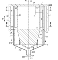
- FIG. 1 is a perspective view of the separation device according to the embodiment.
- FIG. 2 is a cross-sectional view including a rotation center axis in the same separation device with an outer cover attached.
- FIG. 3 is a cross-sectional view corresponding to the cross section taken along line III-III of FIG. 2 with respect to the separation device of the same.
- FIG. 4 is a cross-sectional view corresponding to the IV-IV line cross section of FIG. 2 with respect to the separation device of the same.
- FIG. 5 is a schematic configuration diagram of a separation system including the same separation device.
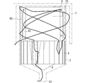
- FIG. 6 is a diagram showing a simulation result of the pressure distribution inside the casing in the same separation device.
- FIG. 7 is a diagram showing a simulation result of a particle trajectory in the same separation device.
- FIG. 1 is a perspective view of the separation device according to the embodiment.
- FIG. 2 is a cross-sectional view including a rotation center axis in the same separation device with an outer cover attached.
- FIG. 8 is a diagram showing a simulation result of the trajectory of another particle in the same separation device.
- FIG. 9 is a cross-sectional view including a rotation center axis in a state where an outer cover is attached in the separation device according to the first modification of the embodiment.
- each figure described in the following embodiment is a schematic view, and the ratio of the size and the thickness of each component in the figure does not necessarily reflect the actual dimensional ratio. ..
- the separation device 1 is provided, for example, on the upstream side of an air conditioner having a ventilation function, and separates solids in air (gas).
- the separation device 1 is installed, for example, on the roof of a facility (house or the like) having a flat roof, or on the ground.
- the air conditioning equipment is, for example, a blower that blows air from the upstream side to the downstream side.
- the blower is, for example, an electric fan.
- the air conditioning equipment is not limited to the blower, and may be, for example, an air conditioning system including a ventilation device, an air conditioner, an air supply cabinet fan, a blower and a heat exchanger.
- the flow rate of the air flowing through the separation device 1 by the air conditioning equipment is, for example, 50 m 3 / h to 500 m 3 / h.
- the amount of air flowing out from the separating device 1 to the air conditioning equipment side is substantially the same as the flow rate of air flowing through the air conditioning equipment.
- the separating device 1 includes a casing 2, a rotating body 3, and blades 4. Further, as shown in FIG. 5, the separation system 10 includes a separation device 1 and a drive device 11.
- the casing 2 has a gas inlet 21, a gas outlet 22, and a solid discharge port 23.
- the rotating body 3 is arranged inside the casing 2.
- the rotating body 3 can rotate about the rotation center axis 30 along the axial direction D1 of the casing 2.
- the blade 4 is arranged between the casing 2 and the rotating body 3.
- the blade 4 rotates together with the rotating body 3.
- the blade 4 has a first end 41 on the gas inlet 21 side and a second end 42 on the gas outlet 22 side.
- the casing 2 has a space 25 on the solid discharge port 23 side of the second end 42 of the blade 4 in the axial direction D1 of the casing 2.
- the solid discharge port 23 is, for example, a hole for discharging the solid contained in the air to the outside of the casing 2.
- the solid discharge port 23 connects the inner space of the casing 2 and the outer space of the casing 2. In other words, the solid discharge port 23 communicates the inside and outside of the casing 2.
- the separating device 1 generates an air flow swirling in the casing 2 in the casing 2 when the rotating body 3 rotates. In the separating device 1, a part of the flow path from the gas inlet 21 to the gas outlet 22 is formed between the casing 2 and the rotating body 3.
- the separation device 1 further includes a separation wall 5.
- the separation wall 5 is arranged in the space 25.
- the separation wall 5 separates the space 25 into a first region R1 on the inner side and a second region R2 on the outer side when viewed from the axial direction D1 of the casing 2.
- the separation device 1 can flow the air flowing into the casing 2 from the upstream side to the downstream side while spirally rotating around the rotating body 3.
- the "upstream side” here means the upstream side (primary side) when viewed in the direction of air flow.
- the “downstream side” means the downstream side (secondary side) when viewed in the direction of air flow.
- the separation device 1 is used, for example, in a state where the gas outlet 22 is located above the gas inlet 21. In this case, in the separation device 1, the air flowing into the flow path from the gas inlet 21 of the casing 2 can be moved while spirally rotating around the rotating body 3 and flowed to the gas outlet 22.
- the separation device 1 has the above-mentioned solid discharge port 23 in order to discharge the solid contained in the air flowing into the casing 2 to the outside of the casing 2. As a result, at least a part of the solid contained in the air flowing into the casing 2 from the gas inlet 21 of the casing 2 is discharged to the outside of the casing 2 from the solid discharge port 23 while passing through the flow path. NS.
- the separation system 10 includes a drive device 11 in addition to the separation device 1.
- the drive device 11 rotationally drives the rotating body 3. That is, the drive device 11 rotates the rotating body 3 around the rotation center axis 30.
- the drive device 11 includes, for example, a motor.
- Examples of the solid in the air include fine particles, dust and the like.
- Examples of the fine particles include particulate matter and the like.
- Particulate matter includes primary particles that are directly released into the air as fine particles, and secondary particles that are released into the air as gas and are produced as fine particles in the air.
- Examples of the primary particles include soil particles (yellow sand and the like), dust, plant particles (pollen and the like), animal particles (mold spores and the like), soot and the like.
- PM1.0, PM2.5 fine particulate matter
- PM10 fine particulate matter
- SPM suspended particulate matter
- PM1.0 is fine particles that pass through a sizing device having a particle size of 1.0 ⁇ m and a collection efficiency of 50%.
- PM2.5 is fine particles that pass through a sizing device having a particle size of 2.5 ⁇ m and a collection efficiency of 50%.
- PM10 is a fine particle that passes through a sizing device having a particle size of 10 ⁇ m and a collection efficiency of 50%.
- SPM is fine particles that pass through a sizing device having a particle size of 10 ⁇ m and a collection efficiency of 100%, which corresponds to PM6.5-7.0 and is slightly smaller than PM10.
- the separation device 1 includes a casing 2, a rotating body 3, blades 4, and a separation wall 5. As shown in FIGS. 1 and 2, the separation device 1 further includes an outflow cylinder portion 6, a rectifying structure 8, and a structure 9. Further, the separation system 10 includes a separation device 1, a drive device 11, and a control device 12.
- the material of the casing 2 is, for example, a metal, but the material is not limited to this, and a resin (for example, ABS resin) may be used. Further, the casing 2 may include a metal portion formed of metal and a resin portion formed of resin.
- the casing 2 includes a tubular portion 20 having a first end 201 and a second end 202, and a bottom portion 24 closing the opening of the second end 202 of the tubular portion 20.
- the casing 2 has a bottomed cylindrical shape.
- the axial direction D1 of the casing 2 is a direction along the central axis of the tubular portion 20.
- the tubular portion 20 has a small diameter portion 211, an enlarged diameter portion 212, and a large diameter portion 213.
- the small diameter portion 211, the enlarged diameter portion 212, and the large diameter portion 213 are arranged in this order in the axial direction D1 of the casing 2.
- the small diameter portion 211 has a gas inlet 21, and the large diameter portion 213 has a gas outlet 22 and a solid discharge port 23.
- the gas inlet 21, the gas outlet 22, and the solid outlet 23 are open to the side of the casing 2.
- the gas inlet 21, the solid discharge port 23, and the gas outlet 22 are arranged in this order.
- a part (downstream end) of the solid discharge port 23 overlaps with the gas outlet 22 in one surface orthogonal to the axial direction D1 of the casing 2 (see FIG. 4).
- the small diameter portion 211 has a gas inflow port 21.
- the small diameter portion 211 has a cylindrical shape with both sides open.
- the gas inflow port 21 is formed on the side surface of the small diameter portion 211.
- the gas inflow port 21 is formed in the small diameter portion 211 near the bottom portion 2111 of the small diameter portion 211.
- Casing 2 has a plurality of gas inlets 21.
- Each gas inlet 21 has a substantially 1/4 arc shape.
- the large diameter portion 213 has a cylindrical shape with both ends open and surrounds the rotating body 3.
- the length of the large diameter portion 213 is longer than the length of the rotating body 3.
- the inner diameter and the outer diameter of the large diameter portion 213 are constant over the total length in the axial direction of the large diameter portion 213.
- the outer diameter and inner diameter of the large diameter portion 213 are larger than the outer diameter and inner diameter of the small diameter portion 211, respectively.
- the solid discharge port 23 is formed on the outer peripheral surface 27 of the casing 2 (here, the outer peripheral surface of the large diameter portion 213).
- the solid discharge port 23 has a slit shape extending along the axial direction of the large diameter portion 213 (axial direction D1 of the casing 2).
- the solid discharge port 23 is formed in a portion corresponding to the space 25 in the large diameter portion 213.
- the solid discharge port 23 is separated from the gas inflow port 21 in the axial direction D1 of the casing 2, and the inside and outside of the cylinder portion 20 (large diameter portion 213) between the first end 201 and the second end 202 of the cylinder portion 20. Communicate.
- the solid discharge port 23 extends in a direction along a tangential direction of the inner peripheral surface 26 (inner peripheral surface of the large diameter portion 213) of the casing 2 when viewed from the axial direction D1 of the casing 2.
- the tangential direction is a direction along the rotation direction A1 (see FIGS. 3 and 4) of the rotating body 3.
- the inner surface of the solid discharge port 23 is a rear inner surface 231 located rearward and a front inner surface 232 located forward in the direction along the rotation direction A1 of the rotating body 3. Has.
- the rear inner surface 231 is connected to the inner peripheral surface 26 (inner peripheral surface of the large diameter portion 213) of the casing 2.
- the outer end P12 on the side farther from the rotating body 3 is located in front of the inner end P11 on the side closer to the rotating body 3 in the rotation direction A1.
- the rear inner surface 231 extends in the tangential direction of the inner peripheral surface 26 at the inner end P11 of the rear inner surface 231.
- the solid discharge port 23 in the casing 2 has a rear inner surface 231 and a front inner surface 232 located in the rear and front, respectively, in the rotation direction A1 of the rotating body 3.
- the front inner surface 232 is substantially parallel to the rear inner surface 231.
- the casing 2 (large diameter portion 213) has a plurality of (two in the illustrated example) solid discharge ports 23.
- the two solid discharge ports 23 are opposite to each other on the outer peripheral surface of the large diameter portion 213.
- solids passing near the inner peripheral surface 26 of the casing 2 here, the inner peripheral surface of the large diameter portion 213) can be discharged from each solid discharge port 23.
- the separation device 1 is provided with a guide wall 28.
- the guide wall 28 is provided in the casing 2.
- the separation device 1 includes a plurality of (two in the illustrated example) guide walls 28.
- the two guide walls 28 have a one-to-one correspondence with the two solid outlets 23.
- the guide wall 28 extends from the inner peripheral surface 26 of the casing 2 to the inside of the casing 2.
- One surface of the guide wall 28 is flush with the front inner surface 232 of the solid discharge port 23.
- the guide wall 28 is formed from the inner peripheral surface 26 of the casing 2 to the front inner surface 232 of the solid discharge port 23 along the one center line of the casing 2 (one center line of the large diameter portion 213; the alternate long and short dash line in FIGS. 3 and 4). (Indicated by).
- the one center line is orthogonal to the rotation center axis 30 of the rotating body 3 and is orthogonal to the one tangential direction.
- the large diameter portion 213 has a gas outlet 22.
- the gas outlet 22 is formed on the side surface of the large diameter portion 213.
- the gas outlet 22 is formed in the large diameter portion 213 near the bottom portion 24.
- the gas outlet 22 is separated from the gas inlet 21 in the axial direction D1 of the casing 2, and the inside and outside of the cylinder 20 (large diameter portion 213) between the first end 201 and the second end 202 of the cylinder 20. Communicate.
- the gas outlet 22 is adjacent to the solid outlet 23 of one of the two solid outlets 23.
- the gas outlet 22 is in front of the adjacent solid discharge port 23 in the rotation direction A1 (see FIGS. 3 and 4) of the rotating body 3.
- the enlarged diameter portion 212 connects the small diameter portion 211 and the large diameter portion 213.
- the enlarged diameter portion 212 has a first end on the small diameter portion 211 side and a second end on the large diameter portion 213 side. The first end of the enlarged diameter portion 212 is connected to the small diameter portion 211.
- the inner space of the enlarged diameter portion 212 is connected to the inner space of the small diameter portion 211.
- the second end of the enlarged diameter portion 212 is connected to the large diameter portion 213.
- the inner space of the enlarged diameter portion 212 is connected to the inner space of the large diameter portion 213.
- the enlarged diameter portion 212 has a tapered cylindrical shape in which the outer diameter and the inner diameter gradually increase as the casing 2 moves away from the small diameter portion 211 and approaches the large diameter portion 213 in the axial direction D1 of the casing 2.
- the outer diameter and inner diameter of the enlarged diameter portion 212 are the same as the outer diameter and inner diameter of the small diameter portion 211 at the end of the casing 2 on the small diameter portion 211 side in the axial direction D1, respectively.
- the outer diameter and inner diameter of the enlarged diameter portion 212 are the same as the outer diameter and inner diameter of the large diameter portion 213 at the end of the casing 2 on the large diameter portion 213 side in the axial direction D1, respectively. That is, in the diameter-expanded portion 212, the opening area gradually increases as the distance from the gas inlet 21 in the axial direction D1 of the casing 2 increases.
- the outflow tube portion 6 is connected to the casing 2.
- the outflow tube portion 6 is connected to the gas outlet 22 on the outer peripheral surface 27 of the casing 2 (large diameter portion 213), for example.
- the inner space 60 of the outflow cylinder portion 6 is connected to the inner space of the cylinder portion 20 (the inner space of the large diameter portion 213) through the gas outlet 22.
- the outflow tube portion 6 is a duct for supplying the gas from which the solid is separated to the outside of the casing 2.
- the outflow cylinder portion 6 is viewed from the axial direction D1 of the casing 2 in the radial direction of the casing 2 at the position where the gas outlet 22 is located and in the direction intersecting the axial direction D1 of the casing 2 from the outer peripheral surface 27 of the casing 2. It is extended.
- the outflow cylinder portion 6 has a square cylinder shape. In the outflow tube portion 6, the opening on the side opposite to the gas outlet 22 side is square, but is not limited to this.
- the rotating body 3 is arranged coaxially with the casing 2 inside the casing 2. "Arranged coaxially with the casing 2" means that the rotating body 3 uses the rotating central axis 30 (see FIG. 2) of the rotating body 3 as the central axis 29 of the casing 2 (central axis of the large diameter portion 213). It means that they are arranged so that they are aligned.
- the material of the rotating body 3 is, for example, a polycarbonate resin.
- the length of the rotating body 3 is shorter than the length of the large diameter portion 213 in the axial direction D1 of the casing 2.
- the rotating body 3 has, for example, a truncated cone shape.
- the rotating body 3 has a first end 31 on the gas inlet 21 side and a second end 32 on the gas outlet 22 side.
- the rotating body 3 has a truncated cone shape whose diameter gradually increases from the first end 31 to the second end 32.
- the rotating body 3 is arranged in the large-diameter portion 213 near the enlarged-diameter portion 212 in the axial direction of the casing 2.
- a plurality of blades 4 (here, 24 blades) are arranged between the casing 2 and the rotating body 3. That is, the separation device 1 includes a plurality of blades 4.
- a plurality of blades 4 are arranged between the casing 2 and the rotating body 3.
- the plurality of blades 4 are connected (coupled) to the rotating body 3 and separated from the casing 2.
- the plurality of blades 4 rotate together with the rotating body 3.
- the plurality of blades 4 are provided on the rotating body 3 over the entire length of the rotating body 3 in the direction along the axial direction D1 of the casing 2. That is, the plurality of blades 4 are provided from the first end 31 to the second end 32 of the rotating body 3.
- the material of the plurality of blades 4 is, for example, a polycarbonate resin.
- the material of the rotating body 3 and the material of the plurality of blades 4 are the same, but the material is not limited to this and may be different.
- the plurality of blades 4 may be integrally formed with the rotating body 3, or may be formed as a separate member from the rotating body 3 and fixed to the rotating body 3 to be connected to the rotating body 3.
- Each of the plurality of blades 4 is arranged so that a gap is formed between each blade 4 and the casing 2 when viewed from the axial direction D1 of the casing 2.
- the distance between the protruding tip of each of the plurality of blades 4 and the outer peripheral surface 37 of the rotating body 3 is the distance between the outer peripheral surface 37 of the rotating body 3 and the inner peripheral surface 26 of the casing 2. Shorter than.
- Each of the plurality of blades 4 is arranged in parallel with the rotation center axis 30 of the rotating body 3 in the space (flow path) between the outer peripheral surface 37 of the rotating body 3 and the inner peripheral surface 26 of the casing 2.
- Each of the plurality of blades 4 has a flat plate shape.
- Each of the plurality of blades 4 has a trapezoidal shape having a height in the direction along the rotation center axis 30 of the rotating body 3 when viewed from the thickness direction thereof.
- Each of the plurality of blades 4 has a predetermined angle (for example, 45 degrees) with respect to one radial direction of the rotating body 3 when viewed from the second end 202 side of the tubular portion 20 in the direction along the axial direction D1 of the casing 2. Only tilted.
- each of the plurality of blades 4 is tilted by a predetermined angle (for example, 45 degrees) with respect to the rotational direction A1 of the rotating body 3 with respect to one radial direction of the rotating body 3.
- the predetermined angle is not limited to 45 degrees, and may be an angle larger than 0 degrees and 90 degrees or less.
- the predetermined angle may be an angle within the range of 10 degrees or more and 80 degrees or less.
- Each of the plurality of blades 4 is not limited to the case where each of the plurality of blades 4 is tilted by a predetermined angle in the rotation direction A1 of the rotating body 3 with respect to the one radial direction of the rotating body 3, for example, the angle formed by the one radial direction of the rotating body 3. May be 0 degrees. That is, a plurality of blades 4 may extend radially from the rotating body 3. As shown in FIGS. 3 and 4, the plurality of blades 4 are arranged at equal intervals in the circumferential direction of the rotating body 3.
- equal angle interval is not limited to the case where the angle intervals are exactly the same, for example, within a predetermined error range (for example, ⁇ 10% of the specified angle interval) with respect to the specified angle interval. It may be an angular interval of.
- the length of each of the plurality of blades 4 is the same as the length of the rotating body 3.
- the length of each of the plurality of blades 4 is not limited to the same as the length of the rotating body 3, and may be longer or shorter than the rotating body 3.
- the length of each of the plurality of blades 4 is shorter than the length of the tubular portion 20.
- the length of each of the plurality of blades 4 is larger than the distance between the end portion of the large diameter portion 213 on the enlarged diameter portion 212 side and the solid discharge port 23. short.
- Each of the plurality of blades 4 has a first end 41 on the gas inlet 21 side and a second end 42 on the gas outlet 22 side and the solid discharge port 23 side in the axial direction D1 of the casing 2.
- the first end 41 of each of the plurality of blades 4 is an end (upstream end) on the first end 201 side of the tubular portion 20 in the axial direction D1 of the casing 2.
- the second end 42 in each of the plurality of blades 4 is an end (downstream end) on the second end 202 side of the tubular portion 20 in the axial direction D1 of the casing 2.
- the casing 2 has a space 25 on the solid discharge port 23 side of the second end 42 of each blade 4 in the axial direction D1.
- the solid discharge port 23 is located at a position overlapping the space 25 in the direction orthogonal to the rotation center axis 30. That is, the solid discharge port 23 is located at a position overlapping the space 25 in the direction orthogonal to the axial direction D1 of the casing 2.
- the solid discharge port 23 is located at a position not overlapping with each blade 4 in the direction orthogonal to the rotation center axis 30. That is, the solid discharge port 23 is located at a position that does not overlap with each of the blades 4 in the direction orthogonal to the axial direction D1 of the casing 2. In other words, there are no blades 4 in the projected area of the solid discharge port 23 when the casing 2 is viewed from the side.
- the ratio of the length of the space 25 to the total of the length of the blade 4 and the length of the space 25 in the axial direction D1 of the tubular portion 20 is, for example, 0.2 or more and 0.8 or less, as an example. , 0.55.
- the structure 9 is arranged in the space 25.
- the structure 9 is, for example, cylindrical.
- the structure 9 is arranged coaxially with the rotating body 3.
- the structure 9 is connected to the rotating body 3.
- the structure 9 has a first end 91 and a second end 92 in the axial direction.
- the first end 91 of the structure 9 is connected to the second end 32 of the rotating body 3.
- the second end 32 of the structure 9 is separated from the rotating body 3 in the axial direction D1 of the casing 2 as compared with the first end 91.
- the outer diameter of the structure 9 is equal to the outer diameter of the rotating body 3 at the second end 32.
- the structure 9 may be separated from the rotating body 3, and may be supported by the casing 2 via one or a plurality of beams.
- the structure 9 may be rotated together with the rotating body 3 or may be rotated separately from the rotating body 3.
- a space 25 is defined between the casing 2 and the structure 9 on the solid discharge port 23 side of the second end 42 of the blade 4.
- the space 25 is defined as a region surrounded by the second end 42 of the blade 4, the inner peripheral surface 26 of the casing 2, and the outer peripheral surface of the structure 9.
- the rectifying structure 8 is located inside the casing 2 between the gas inlet 21 and the rotating body 3, and rectifies the flow of gas flowing into the casing 2.
- the rectifying structure 8 has, for example, a truncated cone shape and is arranged inside the enlarged diameter portion 212.
- the rectifying structure 8 is arranged so that its central axis is aligned with the central axis 29 of the casing 2.
- the gas flowing into the casing 2 from the gas inflow port 21 is introduced into a place far from the outer peripheral surface 37 of the rotating body 3 and closer to the inner peripheral surface 26 of the casing 2 in the radial direction of the rotating body 3. It will be easier.
- the rectifying structure 8 may be supported by, for example, the casing 2 via one or a plurality of beams, or may be connected to the rotating body 3.
- the separation device 1 further includes a separation wall 5 arranged in the space 25.
- the separation wall 5 has an axis along the axial direction D1 of the casing 2, and has a cylindrical shape with both surfaces of the separation wall 5 in the axial direction open. More specifically, the separation wall 5 is cylindrical.
- the separation wall 5 separates the space 25 into a first region R1 on the inner side and a second region R2 on the outer side when viewed from the axial direction D1 of the casing 2.
- the length of the separation wall 5 is shorter than the length of the space 25. In the axial direction D1 of the casing 2, the length of the separation wall 5 is shorter than the length of the solid discharge port 23.
- the separation wall 5 is located at a position overlapping each of the blades 4 in the axial direction D1 of the casing 2.
- the separation wall 5 has a first end 51 on the gas inlet 21 side and a second end 52 on the gas outlet 22 side.
- first gap In the axial direction D1 of the casing 2, there is a gap (first gap) between the first end 51 of the separation wall 5 and the second end 42 of the blade 4.
- second gap In the axial direction D1 of the casing 2, there is a gap (second gap) between the second end 52 of the separation wall 5 and the bottom 24 of the casing 2.
- the first region R1 and the second region R2 are connected by the above two gaps (first gap and second gap).
- the inventors of the present application describe the air flow in the casing 2 for each of the separation device 1 of the embodiment and the separation device of the comparative example having the same structure as the separation device 1 of the embodiment except that the separation wall 5 is not provided.
- the airflow in the casing 2 in each of the separation device 1 and the separation device of the comparative example can be estimated from the result of simulation using, for example, fluid analysis software.
- fluid analysis software for example, ANSYS (R) Fluent (R) can be adopted.
- the inventors of the present application have a gas flow along the axial direction D1 of the casing 2 with respect to the velocity vector of the gas flow velocity in the space 25.
- the direction from the inlet 21 to the gas outlet 22 is positive, it tends to be negative in the relatively inner region (first region R1) in the direction orthogonal to the axial direction D1 of the casing 2, and is relatively outer. It was found that the region (second region R2) tends to be positive.
- the solid (particle) carried to the gas outlet 22 side by the air flow toward the gas outlet 22 in the relatively outer region is at the bottom. If it is not discharged from the solid discharge port 23 by the time it reaches 24, it is carried to the gas outlet 22 side by the airflow toward the gas inlet 21 in the relatively inner region, and to the gas inlet 21 side. It was found that there was a possibility of returning.
- FIG. 6 shows an example of the result of a simulation using fluid analysis software for the airflow in the casing 2 in the separation device 1 of the embodiment.
- the dot-hatched region R0 in the space 25 is directed from the gas inlet 21 to the gas outlet 22 along the axial direction D1 of the casing 2 with respect to the velocity vector of the flow velocity of the fluid in the casing 2. It shows the region where the flow velocity is negative when the direction is positive. Further, the region of the space 25 that is not dot-hatched indicates a region where the velocity vector of the above flow velocity is positive. Although not shown, it has been confirmed that the distribution of the velocity vector of the flow velocity in the space 25 can be the same as that in FIG. 6 even in the separation device of the comparative example.
- the solid returning to the gas inlet 21 side through the relatively inner region moves relatively outward due to the centrifugal force on the way back to the air flow. It was found that it may be carried and headed toward the gas outlet 22 side again.
- the solid in the separator of the comparative example, if the solid is not discharged from the solid outlet 23 by the time it reaches the bottom 24, the solid is directed toward the gas outlet 22 and the gas near the gas outlet 22. It has been found that the gas may reciprocate (vibrate along the axial direction D1) with and from the direction toward the inflow port 21 and may stay near the gas outflow port 22. The solid staying near the gas outlet 22 in this way may be discharged from the gas outlet 22 instead of the solid discharge port 23.
- the separation device 1 includes a separation wall 5 arranged in the space 25.
- the separation wall 5 separates the space 25 into a first region R1 on the inner side and a second region R2 on the outer side when viewed from the axial direction D1 of the casing 2.
- the inner first region R1 is the flow velocity of the gas in the space 25 when the direction from the gas inlet 21 to the gas outlet 22 is positive along the axial direction D1 of the casing 2. This is the region where the velocity vector of is likely to be negative.
- the first region R1 is a region in which the gas flows from the gas outlet 22 toward the gas inlet 21.
- the outer second region R2 has a flow velocity when the direction from the gas inlet 21 to the gas outlet 22 is positive along the axial direction D1 of the casing 2 with respect to the velocity vector of the gas flow velocity in the space 25. This is the region where the velocity vector of is likely to be positive. In other words, the second region R2 is a region in which the gas flows in the direction from the gas inlet 21 to the gas outlet 22. In short, regarding the velocity vector of the velocity of the gas in the space 25, when the direction from the gas inlet 21 to the gas outlet 22 along the axial direction D1 is positive, the velocity vector of the velocity in the second region R2. The vector obtained by subtracting the velocity vector (average of the velocity vectors) of the velocity in the first region R1 from (the average of the velocity vectors) is positive.
- the separation wall 5 moves relatively outward on the way back. Prevent it from happening. That is, when the solid (particle) heading toward the gas outlet 22 side through the second region R2 reaches the bottom 24 and returns to the gas inlet 21 side through the first region R1 in the separation wall 5. , Prevents the movement from the first region R1 to the second region R2 on the way back. This reduces the possibility that the solid stays near the gas outlet 22, reduces the possibility that the solid is discharged from the gas outlet 22, and improves the separation performance that separates the solid contained in the gas from the gas. It becomes possible to plan.
- the separation device 1 the solid that has returned to the vicinity of the blade 4 through the first region R1 passes through a gap (first gap) between the separation wall 5 and the blade 4 to the second region R2, for example. And again through the second region R2 toward the gas outlet 22 side. Therefore, there is a high possibility that this solid will be discharged from the solid discharge port 23 on the way to the gas outlet 22 side through the second region R2 again. Therefore, in the separation device 1, it is possible to further improve the separation performance of separating the solid contained in the gas from the gas.
- an external cover 7 is attached to the separation device 1 as an option.
- the outer cover 7 has a bottomed cylindrical shape.
- the outer cover 7 covers the casing 2 from the bottom 24 side.
- the outer cover 7 has an opening or a notch for exposing the outflow tube portion 6.
- the outer cover 7 prevents the particles discharged from the solid discharge port 23 from being separated from the separation device 1 and scattered around.
- the separation system 10 includes a separation device 1 and a drive device 11 that rotationally drives the rotating body 3 of the separation device 1.
- the drive device 11 includes, for example, a motor that rotationally drives the rotating body 3.
- the drive device 11 may directly or indirectly connect the rotating shaft of the motor to the rotating body 3, or transmit the rotation of the rotating shaft of the motor to the rotating body 3 via the pulley and the rotating belt. You may have it.
- the motor may be arranged inside the casing 2 or may be arranged outside the casing 2.
- the rotation speed of the rotating body 3 rotationally driven by the driving device 11 is, for example, 1500 rpm to 3000 rpm.
- the separation system 10 further includes a control device 12 that controls the drive device 11.
- the control device 12 includes a computer system.
- the computer system mainly consists of a processor and a memory as hardware.
- the function as the control device 12 is realized by the processor executing the program recorded in the memory of the computer system.
- the program may be pre-recorded in the memory of the computer system, may be provided through a telecommunications line, and may be recorded on a non-temporary recording medium such as a memory card, optical disk, hard disk drive, etc. that can be read by the computer system. May be provided.
- the processor of a computer system is composed of one or more electronic circuits including a semiconductor integrated circuit (IC) or a large scale integrated circuit (LSI).
- the integrated circuit such as IC or LSI referred to here has a different name depending on the degree of integration, and includes an integrated circuit called a system LSI, VLSI (Very Large Scale Integration), or ULSI (Ultra Large Scale Integration).
- an FPGA Field-Programmable Gate Array
- a plurality of electronic circuits may be integrated on one chip, or may be distributed on a plurality of chips.
- a plurality of chips may be integrated in one device, or may be distributed in a plurality of devices.
- the computer system referred to here includes a microcontroller having one or more processors and one or more memories. Therefore, the microprocessor is also composed of one or a plurality of electronic circuits including a semiconductor integrated circuit or a large-scale integrated circuit.
- the rotation direction A1 (see FIGS. 3 and 4) of the rotating body 3 rotates from the bottom 24 side in the axial direction D1 of the casing 2, for example. When looking at the body 3, it is in the clockwise direction.
- the separation system 10 rotationally drives the rotating body 3 by the driving device 11.
- the rotating body 3 having the blades 4 by rotating the rotating body 3 having the blades 4, it is possible to apply a force in the rotational direction around the rotation center axis 30 to the air flowing into the inner space (flow path) of the casing 2. Will be.
- a plurality of blades 4 rotate together with the rotating body 3 due to the rotation of the rotating body 3, and the velocity vector of the air flowing in the inner space of the casing 2 is in the direction parallel to the rotation center axis 30. It will have a velocity component and a velocity component in the direction of rotation around the central axis of rotation 30.
- the rotating body 3 and each of the blades 4 rotate to generate a swirling air flow in the casing 2.
- the swirling airflow is a three-dimensional spirally rotating airflow.
- the solid contained in the air flowing into the casing 2 goes from the rotation center axis 30 of the rotating body 3 toward the inner peripheral surface 26 of the casing 2 when spirally rotating in the inner space of the casing 2. Receives centrifugal force in the direction.
- the solid subjected to the centrifugal force moves toward the inner peripheral surface 26 of the casing 2 and spirally rotates around the inner peripheral surface 26 of the casing 2 along the inner peripheral surface 26.
- a part of the solid in the air is discharged from the solid discharge port 23 while passing through the inner space of the casing 2.
- the centrifugal force acting on a solid is proportional to the mass of the solid. Therefore, a solid having a relatively large mass tends to reach the vicinity of the inner peripheral surface 26 of the casing 2 before a solid having a relatively small mass.
- the separating device 1 since a swirling airflow (swirl flow) is generated in the inner space of the casing 2, one of the solids (for example, dust) in the air flowing into the casing 2 from the gas inlet 21 of the casing 2 The portion is discharged through the solid discharge port 23, and a part of the air (cleaned air) from which the solid is separated (removed) flows out from the gas outlet 22 of the casing 2.
- a swirling airflow swirl flow
- the separating device 1 Since the separating device 1 has a space 25 in the casing 2, for example, two adjacent surfaces 37 of the rotating body 3 and the inner peripheral surface 26 of the casing 2 are adjacent to each other in the rotation direction A1 of the rotating body 3. Even if a vortex is generated in the space between the blades 4, it is likely to be rectified into a spiral airflow in the space 25 downstream of each blade 4. When the particles having a large particle size are subjected to centrifugal force, they easily deviate from the air flow, approach the inner peripheral surface 26 of the casing 2, and are easily discharged from the solid discharge port 23.
- the separation device 1 since the separation device 1 includes the separation wall 5, the solid heading toward the gas outlet 22 side through the second region R2 reaches the bottom 24 and passes through the first region R1 to the gas inlet 21 side. When returning to, it is prevented from moving to the second region R2 on the way back. This reduces the possibility of solids (particles) staying near the gas outlet 22. Therefore, it is possible to reduce the possibility that the solid is discharged from the gas outlet 22, and it is possible to improve the separation performance of separating the solid contained in the gas from the gas. Further, the particles that have returned to the vicinity of the blade 4 through the first region R1 again pass through the second region R2 toward the gas outlet 22 side, so that the particles are likely to be discharged from the solid discharge port 23 on the way.
- the inventors of the present application performed a simulation using the particle trajectory analysis software on the simulation result using the above-mentioned fluid analysis software for the separation device 1 of the embodiment.
- the particle trajectory analysis method for example, DPM (Discrete Phase Model) can be adopted.
- 7 and 8 show examples of particle trajectories in the casing 2 of the separation device 1 according to the embodiment with thick lines.
- FIG. 7 shows an example of the trajectory of the particles when the particles toward the gas outlet 22 side through the second region R2 of the space 25 are discharged from the solid discharge port 23 without reaching the bottom 24. ..
- the particles heading toward the gas outlet 22 side through the second region R2 of the space 25 reach the bottom 24, return to the gas inlet 21 side through the first region R1, and then the second again.
- the separation efficiency tends to increase as the rotation speed of the rotating body 3 increases. Further, regarding the separation characteristics of the separation device 1, the separation efficiency tends to increase as the particle size is increased.
- the rotation speed of the rotating body 3 is set so as to separate fine particles having a predetermined particle size or more.
- the fine particles having a specified particle size for example, particles having an aerodynamic particle diameter of 2 ⁇ m are assumed.
- the "aerodynamic particle size” means the diameter of a particle whose aerodynamic behavior is equivalent to a spherical particle having a specific gravity of 1.0.
- the aerodynamic particle size is the particle size obtained from the sedimentation speed of the particles.
- Solids that remain in the air without being separated by the separation device 1 are, for example, fine particles having a smaller particle size than the fine particles that are supposed to be separated by the separation device 1 (in other words, it is assumed that they are separated by the separation device 1). It contains fine particles with a mass smaller than the mass of the fine particles.
- the separation device 1 includes a casing 2, a rotating body 3, and blades 4.
- the casing 2 has a gas inlet 21, a gas outlet 22, and a solid outlet 23.
- the rotating body 3 is arranged inside the casing 2 and can rotate about the rotation center axis 30 along the axial direction D1 of the casing 2.
- the blade 4 is arranged between the casing 2 and the rotating body 3, and rotates together with the rotating body 3.
- the blade 4 has a first end 41 on the gas inlet 21 side and a second end 42 on the gas outlet 22 side.
- the casing 2 has a space 25 on the solid discharge port 23 side of the second end 42 of the blade 4 in the axial direction D1.
- the separation device 1 further includes a separation wall 5 that separates the space 25 into an inner first region R1 and an outer second region R2 when viewed from the axial direction D1 of the casing 2.
- the separation device 1 according to the embodiment can improve the separation performance.
- the separation device 1 is, for example, upstream of an air filter such as a HEPA filter (high efficiency particulate air filter) arranged on the upstream side of an air conditioner in an air purification system installed in a house or the like. Place it on the side and use it.
- the "HEPA filter” is an air filter having a particle collection rate of 99.97% or more and an initial pressure loss of 245 Pa or less with respect to particles having a particle size of 0.3 ⁇ m at a rated flow rate.
- the air filter does not require 100% particle collection efficiency as an essential condition.
- the air purification system it is possible to extend the life of the air filter or the like located on the downstream side of the separation device 1. For example, in an air purification system, it is possible to suppress an increase in pressure loss due to an increase in the total mass of fine particles and the like collected by an air filter. This makes it possible to reduce the frequency of air filter replacement in the air purification system.
- the air purification system is not limited to a configuration in which the air filter and the air conditioning equipment are housed in different housings, and the air filter may be provided in the housing of the air conditioning equipment. In other words, the air conditioner may be equipped with an air filter in addition to the blower.
- Embodiment is only one of the various embodiments of the present disclosure.
- the embodiment can be variously changed according to the design and the like as long as the object of the present disclosure can be achieved.
- the separating device 1 does not have to include the structure 9.
- the separation wall 5 may be located at a position overlapping the rotating body 3 in the axial direction D1 of the casing 2.
- the separation wall 5 may be located at a position overlapping the blade 4 in the axial direction D1 of the casing 2 (see FIG. 2).
- the shape of the separation wall 5 is not limited to a cylindrical shape, and may be a tapered cylinder whose diameter on the first end 51 side is smaller than the diameter on the second end 52 side, or on the second end 52 side.
- the diameter of the cylinder may be smaller than that of the first end 51 side.
- the separation device 1 may include a plurality of separation walls 5.
- the plurality of separation barriers 5 may include two separation walls 5 having the same diameter and coaxially arranged so as not to overlap the axial direction D1, or may have different diameters and overlap or overlap the axial direction D1. It may include two separation barriers 5 arranged coaxially so as not to be.
- the length of the solid discharge port 23 (dimensions along the axial direction D1 of the casing 2) may be appropriately adjusted according to the separation performance required for the separation device 1.
- the solid discharge port 23 is not limited to a position that does not overlap with the blade 4 in the direction orthogonal to the rotation center axis 30, but at least a part thereof overlaps with the blade 4 in the direction orthogonal to the rotation center axis 30. It may be in a position to do. In this case, the solid discharge port 23 does not overlap with any of the plurality of blades 4 when viewed from the axial direction D1 of the casing 2 (that is, when viewed from the direction along the rotation center axis 30). In this case, for example, the protrusion lengths of the plurality of blades 4 from the outer peripheral surface 37 of the rotating body 3 are determined so that each blade 4 does not collide with the solid discharge port 23.
- the number of solid discharge ports 23 included in the casing 2 is not limited to two, and may be one or three or more.
- the shapes of the plurality of solid discharge ports 23 are not limited to the case where they are the same as each other, but may be different.
- a discharge cylinder portion extending in the opening direction of the solid discharge port 23 may be formed on the peripheral edge of the solid discharge port 23 on the outer peripheral surface 27 of the casing 2.
- the tip on the casing 2 side in the protruding direction from the rotating body 3 is located forward of the base end on the rotating body 3 side in the rotating direction A1 of the rotating body 3. May be.
- each of the plurality of blades 4 may have a shape including one or more curved portions such as an arc shape.
- each of the plurality of blades 4 may be formed in a spiral shape around the rotation center axis 30 of the rotating body 3.
- the "spiral shape” is not limited to a spiral shape having a rotation speed of 1 or more, but also includes a part of a spiral shape having a rotation speed of 1.
- the rotating body 3 may be cylindrical.
- the rotating body 3 may have a bottomed cylinder shape having a bottom wall on the gas inflow port 21 side.
- the rotating body 3 has a bottomed cylinder shape, it is preferable that the rotating body 3 has a reinforcing wall inside.
- the rotating body 3 may include a plurality of rotating members.
- the structure 9 may form a part of the rotating body 3.
- the rotating members arranged in the direction along the central axis 29 of the casing 2 are connected to each other.
- the structure 9 may have a columnar shape or another shape such as a truncated cone shape.
- the structure 9 may be provided with a reinforcing wall inside.
- the casing 2 may have a plurality of gas outlets 22.
- the casing 2 may have a plurality of outflow tube portions 6.
- the plurality of outflow tube portions 6 may be arranged in the outer peripheral direction of the casing 2 or may be located at different positions in the axial direction D1 of the casing 2.
- the separation device 1 may be configured not to include the outflow cylinder portion 6 as long as it has the gas outlet 22.
- the gas flowing into the casing 2 from the gas inlet 21 of the casing 2 is not limited to air, and may be, for example, exhaust gas or the like.
- the separation device (1) of the first aspect includes a casing (2), a rotating body (3), and a blade (4).
- the casing (2) has a gas inlet (21), a gas outlet (22), and a solid outlet (23).
- the rotating body (3) is arranged inside the casing (2).
- the rotating body (3) can rotate about the rotation center axis (30) along the axial direction (D1) of the casing (2).
- the blade (4) is arranged between the casing (2) and the rotating body (3).
- the blade (4) rotates together with the rotating body (3).
- the blade (4) has a first end (41) on the gas inlet (21) side and a second end (42) on the gas outlet (22) side.
- the casing (2) has a space (25) on the solid discharge port (23) side of the second end (42) of the blade (4) in the axial direction (D1).
- the separation device (1) further comprises a separation wall (5).
- the separation wall (5) separates the space (25) into an inner first region (R1) and an outer second region (R2) when viewed from the axial direction (D1) of the casing (2).
- a solid (particle) heading toward the gas outlet (22) through the second region (R2) reaches the gas outlet (22) and passes through the first region (R1).
- a solid (particle) heading toward the gas outlet (22) through the second region (R2) reaches the gas outlet (22) and passes through the first region (R1).
- This can reduce the possibility of solids staying near the gas outlet (22). Therefore, it is possible to reduce the possibility that the solid is discharged from the gas outlet (22), and it is possible to improve the separation performance for separating the solid contained in the gas from the gas.
- the separation wall (5) has an axis along the axial direction (D1) of the casing (2), and both surfaces in the axial direction are open. It is a tubular shape.
- the reliability of separation between the first region (R1) and the second region (R2) of the space (25) can be improved, and the separation performance for separating the solid contained in the gas from the gas can be improved. It becomes possible.
- the separation wall (5) is cylindrical in the second aspect.
- the reliability of separation between the first region (R1) and the second region (R2) of the space (25) can be further improved, and the separation performance for separating the solid contained in the gas from the gas can be improved. It is possible to plan.
- the velocity vector of the gas flow velocity in the space (25) is the axial direction (D1) of the casing (2). From the velocity vector of the flow velocity in the second region (R2) to the velocity of the flow velocity in the first region (R1) when the direction from the gas inlet (21) to the gas outlet (22) is positive. The vector obtained by subtracting the vector is positive.
- the separation wall (5) overlaps with the blade (4) in the axial direction (D1) of the casing (2). In position.
- the region of the space (25) that overlaps with the blade (4) in the axial direction of the casing (2) can be separated into a first region (R1) and a second region (R2). can.
- the solid discharge port (23) is formed on the outer peripheral surface of the casing (2) and is formed along the axial direction (D1). It has a slit shape that extends.
- the solid (particle) heading toward the gas outlet (22) through the second region (R2) is easily discharged from the solid discharge port (23) on the way, and the solid contained in the gas. It is possible to improve the separation performance of separating the gas from the gas.
- a part of the solid discharge port (23) overlaps with the gas outlet (22) in one surface orthogonal to the axial direction of the casing (2). doing.
- the part of the solid discharge port (23) is behind the gas outlet (22) in the rotation direction (A1) of the rotating body (3).
- the solid (particle) can be easily discharged from the solid discharge port (23), and the separation performance for separating the solid contained in the gas from the gas can be improved.
- the separation device (1) of the eighth aspect has the structure (9) arranged along the rotation center axis (30) of the rotating body (3) in any one of the first to seventh aspects. Further prepare. At least a part of the structure (9) is arranged in the space (25).
- the space (25) between the structure (9) and the casing (2) can be separated into a first region (R1) and a second region (R2).
- the separation system (10) of the ninth aspect includes a separation device (1) of any one of the first to eighth aspects, and a drive device (11) for rotationally driving the rotating body (3).
- the configurations according to the second to eighth aspects are not essential configurations for the separation device (1) and can be omitted as appropriate.
Abstract
本開示の課題は、気体に含まれる固体を気体から分離する分離性能の向上を図ることにある。分離装置(1)は、ケーシング(2)と、回転体(3)と、羽根(4)と、を備える。ケーシング(2)は、気体流入口(21)と気体流出口と固体排出口(23)とを有する。回転体(3)は、ケーシング(2)の内側に配置されている。回転体(3)は、ケーシング(2)の軸方向(D1)に沿った回転中心軸(30)を中心として回転可能である。羽根(4)は、ケーシング(2)と回転体(3)との間に配置されている。羽根(4)は、回転体(3)と一緒に回転する。羽根(4)は、気体流入口(21)側の第1端(41)と気体流出口(22)側の第2端(42)とを有する。ケーシング(2)は、軸方向(D1)において、羽根(4)の第2端(42)よりも固体排出口(23)側に空間(25)を有する。分離装置(1)は、分離壁(5)を更に備える。分離壁(5)は、空間(25)を、ケーシング(2)の軸方向(D1)から見て内側の第1領域(R1)と外側の第2領域(R2)とに分離する。
Description
本開示は、分離装置及び分離システムに関し、より詳細には、気体に含まれている固体を気体から分離する分離装置、及びそれを備える分離システムに関する。
従来、分離装置として、円筒形閉じ込め壁を有するチャンバと、シャフトに固定された複数のブレードを有するドライビングロータと、を備える遠心分離装置が知られている(特許文献1)。
円筒形閉じ込め壁は、シャフトを囲んで前記シャフトと同軸的に配置されている。ブレードは、シャフトと円筒形閉じ込め壁との間に配置されシャフトに連結されている。ここにおいて、円筒形閉じ込め壁は、インレット開口(流入口)とアウトレット開口(流出口)と除去開口(排出口)とを有している。除去開口は、インレット開口に近い位置よりもアウトレット開口に近い位置に設けられている。
分離装置では、気体に含まれる固体を気体から分離する分離性能の向上が望まれている。
本開示の目的は、気体に含まれる固体を気体から分離する分離性能の向上を図ることが可能な分離装置及び分離システムを提供することにある。
本開示の一態様に係る分離装置は、ケーシングと、回転体と、羽根と、を備える。前記ケーシングは、気体流入口と気体流出口と固体排出口とを有する。前記回転体は、前記ケーシングの内側に配置されている。前記回転体は、前記ケーシングの軸方向に沿った回転中心軸を中心として回転可能である。前記羽根は、前記ケーシングと前記回転体との間に配置されている。前記羽根は、前記回転体と一緒に回転する。前記羽根は、前記気体流入口側の第1端と前記気体流出口側の第2端とを有する。前記ケーシングは、前記軸方向において、前記羽根の前記第2端よりも前記固体排出口側に空間を有する。前記分離装置は、分離壁を更に備える。前記分離壁は、前記空間を、前記ケーシングの軸方向から見て内側の第1領域と外側の第2領域とに分離する。
本開示の一態様に係る分離システムは、前記分離装置と、駆動装置と、を備える。前記駆動装置は、前記回転体を回転駆動する。
以下、実施形態に係る分離装置、及び分離システムについて、図面を用いて説明する。ただし、下記の実施形態は、本開示の様々な実施形態の1つに過ぎない。下記の実施形態は、本開示の目的を達成できれば、設計等に応じて種々の変更が可能である。また、下記の実施形態において説明する各図は、模式的な図であり、図中の各構成要素の大きさ及び厚さそれぞれの比が必ずしも実際の寸法比を反映しているとは限らない。
(1)概要
分離装置1は、例えば、送風機能を有する空調設備の上流側に設けられ、空気(気体)中の固体を分離する。分離装置1は、例えば、平らな屋根を有する施設(住居等)の屋上、又は地面に設置される。空調設備は、例えば、上流側から下流側へ空気を送風する送風装置である。送風装置は、例えば、電動ファンである。空調設備は、送風装置に限らず、例えば、換気装置、エアコンディショナ、給気キャビネットファン、送風装置と熱交換器とを備える空気調和システムでもよい。空調設備により分離装置1に流す空気の流量は、例えば、50m3/h~500m3/hである。分離装置1から空調設備側への空気の流出量は、空調設備を流れる空気の流量と略同じである。
分離装置1は、例えば、送風機能を有する空調設備の上流側に設けられ、空気(気体)中の固体を分離する。分離装置1は、例えば、平らな屋根を有する施設(住居等)の屋上、又は地面に設置される。空調設備は、例えば、上流側から下流側へ空気を送風する送風装置である。送風装置は、例えば、電動ファンである。空調設備は、送風装置に限らず、例えば、換気装置、エアコンディショナ、給気キャビネットファン、送風装置と熱交換器とを備える空気調和システムでもよい。空調設備により分離装置1に流す空気の流量は、例えば、50m3/h~500m3/hである。分離装置1から空調設備側への空気の流出量は、空調設備を流れる空気の流量と略同じである。
図1~図4に示すように、分離装置1は、ケーシング2と、回転体3と、羽根4と、を備える。また、分離システム10は、図5に示すように、分離装置1と、駆動装置11と、を備える。
ケーシング2は、気体流入口21と気体流出口22と固体排出口23とを有する。回転体3は、ケーシング2の内側に配置されている。回転体3は、ケーシング2の軸方向D1に沿った回転中心軸30を中心として回転可能である。羽根4は、ケーシング2と回転体3との間に配置されている。羽根4は、回転体3と一緒に回転する。羽根4は、気体流入口21側の第1端41と気体流出口22側の第2端42とを有する。ケーシング2は、ケーシング2の軸方向D1において、羽根4の第2端42よりも固体排出口23側に空間25を有する。
固体排出口23は、例えば空気に含まれている固体をケーシング2の外側に排出するための孔である。固体排出口23は、ケーシング2の内側空間とケーシング2の外側空間とをつないでいる。言い換えれば、固体排出口23は、ケーシング2の内外を連通させる。分離装置1は、回転体3の回転時に、ケーシング2内にケーシング2内を旋回する気流を発生させる。分離装置1では、ケーシング2と回転体3との間に、気体流入口21から気体流出口22に向かう流路の一部が形成されている。
分離装置1は、分離壁5を更に備える。分離壁5は、空間25に配置される。分離壁5は、空間25を、ケーシング2の軸方向D1から見て内側の第1領域R1と外側の第2領域R2とに分離する。
分離装置1は、上流側からケーシング2に流入した空気を、回転体3のまわりで螺旋状に回転させながら、下流側に流すことができる。ここにおける「上流側」は、空気の流れる方向でみたときの上流側(一次側)を意味する。また、「下流側」は、空気の流れる方向でみたときの下流側(二次側)を意味する。分離装置1は、例えば、気体流出口22が気体流入口21よりも上方に位置する状態で使用される。この場合、分離装置1では、ケーシング2の気体流入口21から流路に流入した空気を、回転体3のまわりで螺旋状に回転させながら移動させ、気体流出口22に流すことができる。
分離装置1は、ケーシング2に流入した空気に含まれている固体をケーシング2の外側に排出するために、上述の固体排出口23を有している。これにより、ケーシング2の気体流入口21からケーシング2内に流入した空気に含まれている固体の少なくとも一部は、流路を通過する途中で、固体排出口23からケーシング2の外部に排出される。
また、分離システム10は、上述のように、分離装置1に加えて、駆動装置11を備える。駆動装置11は、回転体3を回転駆動する。つまり、駆動装置11は、回転中心軸30を中心として回転体3を回転させる。駆動装置11は、例えば、モータを含む。
空気中の固体としては、例えば、微粒子、塵埃等が挙げられる。微粒子としては、例えば、粒子状物質等を挙げることができる。粒子状物質としては、微粒子として直接空気中に放出される一次生成粒子、気体として空気中に放出されたものが空気中で微粒子として生成される二次生成粒子等がある。一次生成粒子としては、例えば、土壌粒子(黄砂等)、粉塵、植物性粒子(花粉等)、動物性粒子(カビの胞子等)、煤等が挙げられる。粒子状物質は、大きさの分類として、例えば、PM1.0、PM2.5(微小粒子状物質)、PM10、SPM(浮遊粒子状物質)等を挙げることができる。PM1.0は、粒子径1.0μmで50%の捕集効率を持つ分粒装置を透過する微粒子である。PM2.5は、粒子径2.5μmで50%の捕集効率を持つ分粒装置を透過する微粒子である。PM10は、粒子径10μmで50%の捕集効率を持つ分粒装置を透過する微粒子である。SPMは、粒子径10μmで100%の捕集効率を持つ分粒装置を透過する微粒子であり、PM6.5-7.0に相当し、PM10よりも少し小さな微粒子である。
(2)詳細
上述のように、分離装置1は、ケーシング2と、回転体3と、羽根4と、分離壁5と、を備える。図1、図2に示すように、分離装置1は、流出筒部6と、整流構造8と、構造体9と、を更に備える。また、分離システム10は、分離装置1と、駆動装置11と、制御装置12と、を備える。
上述のように、分離装置1は、ケーシング2と、回転体3と、羽根4と、分離壁5と、を備える。図1、図2に示すように、分離装置1は、流出筒部6と、整流構造8と、構造体9と、を更に備える。また、分離システム10は、分離装置1と、駆動装置11と、制御装置12と、を備える。
ケーシング2の材料は、例えば、金属であるが、これに限らず、樹脂(例えば、ABS樹脂)であってもよい。また、ケーシング2は、金属により形成されている金属部と、樹脂により形成されている樹脂部と、を含んでいてもよい。
ケーシング2は、第1端201及び第2端202を有する筒部20と、筒部20の第2端202の開口を塞いでいる底部24と、を備える。実施形態に係る分離装置1では、ケーシング2は、有底筒状である。ケーシング2の軸方向D1は、筒部20の中心軸に沿った方向である。
筒部20は、小径部211と、拡径部212と、大径部213と、を有する。筒部20では、ケーシング2の軸方向D1において、小径部211、拡径部212、及び大径部213が、この順に並んでいる。筒部20では、小径部211が気体流入口21を有し、大径部213が気体流出口22及び固体排出口23を有している。気体流入口21、気体流出口22及び固体排出口23は、ケーシング2の側方に開放されている。ケーシング2の軸方向D1において、気体流入口21、固体排出口23、気体流出口22がこの順に並んでいる。ケーシング2の軸方向D1と直交する一面内において、固体排出口23の一部(下流側の端)が気体流出口22と重複している(図4参照)。
小径部211は、気体流入口21を有する。小径部211は、両面が開口した円筒状である。気体流入口21は、小径部211の側面に形成されている。気体流入口21は、小径部211において小径部211の底部2111の近くに形成されている。
ケーシング2は、複数の気体流入口21を有する。各気体流入口21は、略1/4円弧状である。
大径部213は、両端が解放された円筒状であり、回転体3を囲んでいる。ケーシング2の軸方向D1(大径部213の軸方向)において、大径部213の長さは、回転体3の長さよりも長い。大径部213の内径及び外径は、大径部213の軸方向の全長にわたって、それぞれ一定である。大径部213の外径及び内径は、それぞれ、小径部211の外径及び内径よりも大きい。
固体排出口23は、ケーシング2の外周面27(ここでは、大径部213の外周面)に形成されている。固体排出口23は、大径部213の軸方向(ケーシング2の軸方向D1)に沿って延びるスリット状である。固体排出口23は、大径部213において、空間25に対応する部分に形成されている。
固体排出口23は、ケーシング2の軸方向D1において気体流入口21から離れており、筒部20の第1端201と第2端202との間において筒部20(大径部213)の内外を連通させる。固体排出口23は、ケーシング2の軸方向D1から見て、ケーシング2の内周面26(大径部213の内周面)の一接線方向に沿った方向に延びている。ここにおいて、一接線方向は、回転体3の回転方向A1(図3、図4参照)に沿った方向である。
より詳細には、固体排出口23の内面は、図3、図4に示すように、回転体3の回転方向A1に沿った方向において後方に位置する後内面231及び前方に位置する前内面232を有する。
後内面231は、ケーシング2の内周面26(大径部213の内周面)につながっている。後内面231では、回転体3から遠い側の外側端P12が回転体3に近い側の内側端P11よりも回転方向A1の前方に位置している。ケーシング2の軸方向D1に直交する断面において、後内面231は、後内面231の内側端P11における内周面26の接線方向に延びている。
前内面232では、回転体3から遠い側の外側端P22が回転体3に近い側の内側端P21よりも回転方向A1の前方に位置している。要するに、分離装置1では、ケーシング2における固体排出口23が、回転体3の回転方向A1においてそれぞれ後方及び前方に位置する後内面231及び前内面232を有する。ケーシング2の軸方向D1に直交する断面において、前内面232は、後内面231と略平行である。
ケーシング2(大径部213)は、複数(図示例では、2つ)の固体排出口23を有する。2つの固体排出口23は、大径部213の外周面において、互いに反対側にある。分離装置1では、ケーシング2の内周面26(ここでは、大径部213の内周面)付近を通っている固体を、各固体排出口23から排出することが可能となる。
分離装置1は、ガイド壁28を備えている。ガイド壁28は、ケーシング2に設けられている。分離装置1は、複数(図示例では、2つ)のガイド壁28を備えている。2つのガイド壁28は、2つの固体排出口23に1対1に対応する。
ガイド壁28は、ケーシング2の内周面26からケーシング2の内側に延びている。ガイド壁28の一面は、固体排出口23の前内面232と面一である。ガイド壁28は、ケーシング2の内周面26から固体排出口23の前内面232に沿って、ケーシング2の一中心線(大径部213の一中心線;図3、図4には一点鎖線で示してある)まで延びている。上記一中心線は、回転体3の回転中心軸30に直交しかつ上記一接線方向に直交する。
大径部213は、気体流出口22を有する。気体流出口22は、大径部213の側面に形成されている。気体流出口22は、大径部213において底部24の近くに形成されている。気体流出口22は、ケーシング2の軸方向D1において気体流入口21から離れており、筒部20の第1端201と第2端202との間において筒部20(大径部213)の内外を連通させる。気体流出口22は、2つの固体排出口23のうち一方の固体排出口23に隣接している。気体流出口22は、回転体3の回転方向A1(図3、図4参照)において、隣接する固体排出口23よりも前方にある。
拡径部212は、小径部211と大径部213との間をつないでいる。拡径部212は、小径部211側の第1端と、大径部213側の第2端と、を有する。拡径部212の第1端は、小径部211とつながっている。拡径部212の内側空間は、小径部211の内側空間につながっている。拡径部212の第2端は、大径部213とつながっている。拡径部212の内側空間は、大径部213の内側空間につながっている。拡径部212は、ケーシング2の軸方向D1において小径部211から離れて大径部213に近づくにつれて外径及び内径が漸増するテーパ円筒状である。拡径部212の外径及び内径は、それぞれ、ケーシング2の軸方向D1における小径部211側の端で小径部211の外径及び内径と同じである。拡径部212の外径及び内径は、それぞれ、ケーシング2の軸方向D1における大径部213側の端で大径部213の外径及び内径と同じである。つまり、拡径部212では、ケーシング2の軸方向D1において気体流入口21から離れるにつれて開口面積が漸増している。
流出筒部6は、ケーシング2につながっている。流出筒部6は、例えば、ケーシング2(大径部213)の外周面27において気体流出口22につながっている。流出筒部6の内側空間60は、気体流出口22を通して、筒部20の内側空間(大径部213の内側空間)につながっている。
流出筒部6は、固体が分離された気体をケーシング2の外部へ供給するためのダクトである。流出筒部6は、ケーシング2の軸方向D1から見て、ケーシング2の外周面27から、気体流出口22がある位置でのケーシング2の径方向及びケーシング2の軸方向D1と交差する方向に延びている。流出筒部6は、角筒状である。流出筒部6では、気体流出口22側とは反対側の開口が、正方形状であるが、これに限らない。
回転体3は、ケーシング2の内側でケーシング2と同軸的に配置されている。「ケーシング2と同軸的に配置されている」とは、回転体3が、回転体3の回転中心軸30(図2参照)をケーシング2の中心軸29(大径部213の中心軸)に揃えるように配置されていることを意味する。回転体3の材料は、例えば、ポリカーボネート樹脂である。
回転体3の回転中心軸30に沿った方向において、回転体3の長さは、ケーシング2の軸方向D1における大径部213の長さよりも短い。
回転体3は、例えば円錐台状である。回転体3は、気体流入口21側の第1端31と、気体流出口22側の第2端32と、を有する。回転体3は、第1端31から第2端32に向かって徐々に径が大きくなる円錐台状である。回転体3は、大径部213内において、ケーシング2の軸方向において拡径部212の近くに配置されている。
分離装置1では、ケーシング2と回転体3との間には、複数(ここでは、24枚)の羽根4が配置されている。つまり、分離装置1は、複数の羽根4を備えている。分離装置1では、ケーシング2と回転体3との間に、複数の羽根4が配置されている。複数の羽根4は、回転体3につながって(結合されて)おり、ケーシング2からは離れている。複数の羽根4は、回転体3と一緒に回転する。
複数の羽根4は、ケーシング2の軸方向D1に沿った方向において回転体3の全長に亘って回転体3に設けられている。つまり、複数の羽根4は、回転体3の第1端31から第2端32に亘って設けられている。複数の羽根4の材料は、例えば、ポリカーボネート樹脂である。分離装置1では、回転体3の材料と複数の羽根4の材料とが同じであるが、これに限らず、異なってもよい。複数の羽根4は、回転体3と一体に形成されていてもよいし、回転体3と別部材として形成され回転体3に固定されることで回転体3に連結されていてもよい。
複数の羽根4の各々は、ケーシング2の軸方向D1から見て各羽根4とケーシング2との間に隙間が形成されるように配置されている。言い換えれば、分離装置1では、複数の羽根4の各々とケーシング2の内周面26との間に隙間がある。回転体3の径方向において、複数の羽根4の各々の突出先端と回転体3の外周面37との間の距離は、回転体3の外周面37とケーシング2の内周面26との距離よりも短い。
複数の羽根4の各々は、回転体3の外周面37とケーシング2の内周面26との間の空間(流路)において回転体3の回転中心軸30と平行に配置されている。複数の羽根4の各々は、平板状である。複数の羽根4の各々は、その厚さ方向から見て回転体3の回転中心軸30に沿った方向に高さを有する台形状である。複数の羽根4の各々は、ケーシング2の軸方向D1に沿った方向において筒部20の第2端202側から見て、回転体3の一径方向に対して所定角度(例えば、45度)だけ傾いている。ここにおいて、複数の羽根4の各々では、回転体3からの突出方向におけるケーシング2側の先端が、回転体3側の基端よりも、回転体3の回転方向A1(図3、図4参照)において後方に位置している。つまり、分離装置1では、複数の羽根4の各々が、回転体3の一径方向に対して回転体3の回転方向A1に所定角度(例えば、45度)だけ傾いている。所定角度は、45度に限らず、0度よりも大きく90度以下の角度であってもよい。例えば、所定角度は、10度以上80度以下の範囲内の角度であってもよい。複数の羽根4の各々は、回転体3の一径方向に対して回転体3の回転方向A1に所定角度だけ傾いている場合に限らず、例えば、回転体3の一径方向とのなす角度が0度であってもよい。つまり、複数の羽根4が回転体3から放射状に延びていてもよい。複数の羽根4は、図3、図4に示すように回転体3の周方向において等角度間隔で離れて配置されている。ここでいう「等角度間隔」とは、厳密に同じ角度間隔である場合だけに限らず、例えば、規定の角度間隔に対して所定の誤差範囲(例えば、規定の角度間隔の±10%)内の角度間隔であってもよい。
ケーシング2の軸方向D1において、複数の羽根4の各々の長さは、回転体3の長さと同じである。ここにおいて、複数の羽根4の各々の長さは、回転体3の長さと同じである場合に限らず、回転体3よりも長くてもよいし、短くてもよい。
ケーシング2の軸方向D1において、複数の羽根4の各々の長さは、筒部20の長さよりも短い。回転体3の回転中心軸30に沿った方向において、複数の羽根4の各々の長さは、大径部213における拡径部212側の端部と固体排出口23との間の距離よりも短い。
複数の羽根4の各々は、ケーシング2の軸方向D1において、気体流入口21側の第1端41と、気体流出口22側及び固体排出口23側の第2端42と、を有する。複数の羽根4の各々における第1端41は、ケーシング2の軸方向D1における筒部20の第1端201側の端(上流端)である。複数の羽根4の各々における第2端42は、ケーシング2の軸方向D1における筒部20の第2端202側の端(下流端)である。
ケーシング2は、その軸方向D1において、各羽根4の第2端42よりも固体排出口23側に空間25を有する。分離装置1では、固体排出口23は、回転中心軸30に直交する方向において空間25と重なる位置にある。つまり、固体排出口23は、ケーシング2の軸方向D1に直交する方向において空間25と重なる位置にある。また、分離装置1では、固体排出口23は、回転中心軸30に直交する方向において各羽根4と重複しない位置にある。つまり、固体排出口23は、ケーシング2の軸方向D1に直交する方向において各羽根4と重複しない位置にある。言い換えれば、ケーシング2を側方から見たときの固体排出口23の投影領域には、各羽根4がない。
分離装置1では、筒部20の軸方向D1における羽根4の長さと空間25の長さとの合計に対する空間25の長さの比率は、例えば、0.2以上0.8以下であり、一例として、0.55である。
分離装置1では、構造体9が、空間25に配置される。構造体9は、例えば円筒状である。構造体9は、回転体3と同軸的に配置されている。構造体9は、回転体3に連結されている。構造体9は、軸方向における第1端91と第2端92とを有する。構造体9の第1端91は、回転体3の第2端32とつながっている。構造体9の第2端32は、ケーシング2の軸方向D1において、第1端91に比べて回転体3から離れている。構造体9の外径は、第2端32における回転体3の外径と等しい。なお、構造体9は、例えば、回転体3から離れておりケーシング2に1又は複数の梁を介して支持されていてもよい。構造体9は、回転体3と一緒に回転してもよいし、回転体3とは別に回転してもよい。
分離装置1では、羽根4の第2端42よりも固体排出口23側において、ケーシング2と構造体9との間に、空間25が規定される。要するに、分離装置1において空間25は、羽根4の第2端42、ケーシング2の内周面26及び構造体9の外周面で囲まれる領域として規定される。
整流構造8は、ケーシング2の内側において気体流入口21と回転体3との間に位置しており、ケーシング2に流入する気体の流れを整流する。整流構造8は、例えば、円錐台状であり、拡径部212の内側に配置されている。整流構造8は、その中心軸がケーシング2の中心軸29と揃うように配置されている。これにより、分離装置1では、気体流入口21からケーシング2内に流入した気体を回転体3の径方向において回転体3の外周面37から遠くケーシング2の内周面26に近いところへ導入しやすくなる。整流構造8は、例えば、ケーシング2に1又は複数の梁を介して支持されていてもよいし、回転体3に連結されていてもよい。
上述のように、分離装置1は、空間25内に配置されている分離壁5を更に備えている。分離壁5は、ケーシング2の軸方向D1に沿った軸を有し、分離壁5の軸方向の両側の面が開口した筒状である。より詳細には、分離壁5は、円筒状である。分離壁5は、空間25を、ケーシング2の軸方向D1から見て内側の第1領域R1と外側の第2領域R2とに分離する。
ケーシング2の軸方向D1において、分離壁5の長さは、空間25の長さよりも短い。ケーシング2の軸方向D1において、分離壁5の長さは、固体排出口23の長さよりも短い。分離壁5は、ケーシング2の軸方向D1において、各羽根4と重複する位置にある。
分離壁5は、気体流入口21側の第1端51と、気体流出口22側の第2端52と、を有する。ケーシング2の軸方向D1において、分離壁5の第1端51と羽根4の第2端42との間には、隙間(第1の隙間)がある。ケーシング2の軸方向D1において、分離壁5の第2端52とケーシング2の底部24との間には、隙間(第2の隙間)がある。第1領域R1と第2領域R2とは、上記の2つの隙間(第1の隙間及び第2の隙間)によってつながっている。
本願発明者らは、実施形態の分離装置1、及び分離壁5を備えていない以外は実施形態の分離装置1と同様の構造を有する比較例の分離装置それぞれについて、ケーシング2内での気流についての解析を行った。分離装置1及び比較例の分離装置それぞれにおけるケーシング2内での気流については、例えば、流体解析ソフトウェアを用いたシミュレーションの結果により推測することが可能である。流体解析ソフトウェアとしては、例えば、ANSYS(R) Fluent(R)を採用することができる。
シミュレーションの結果、本願発明者らは、実施形態の分離装置1及び比較例の分離装置の各々では、空間25内での気体の流速の速度ベクトルについて、ケーシング2の軸方向D1に沿って気体流入口21から気体流出口22へ向かう向きを正としたときに、ケーシング2の軸方向D1と直交する方向において相対的に内側の領域(第1領域R1)では負となりやすく、相対的に外側の領域(第2領域R2)では正となりやすい、という知見を得た。そのため、実施形態の分離装置1及び比較例の分離装置の各々においては、相対的に外側の領域で気体流出口22へ向かう気流により気体流出口22側へと運ばれる固体(粒子)が、底部24に到達するまでに固体排出口23から排出されなかった場合、相対的に内側の領域で気体流入口21へ向かう気流により気体流出口22側へと運ばれて、気体流入口21側へと戻る場合があることが見出された。
図6は、実施形態の分離装置1におけるケーシング2内での気流について、流体解析ソフトウェアを用いたシミュレーションの結果の一例を示す。図6において、空間25のうちでドットハッチングされている領域R0は、ケーシング2内の流体の流速の速度ベクトルについて、ケーシング2の軸方向D1に沿って気体流入口21から気体流出口22へ向かう向きを正としたときに、流速が負となる領域を示している。また、空間25のうちでドットハッチングされていない領域は、上記の流速の速度ベクトルが正となる領域を示している。図示は省略するが、比較例の分離装置においても、空間25における流速の速度ベクトルの分布は図6と同様のものが得られることが確かめられている。
さらに、シミュレーションの結果、比較例の分離装置では、相対的に内側の領域を通って気体流入口21側へと戻る固体が、その戻る途中で遠心力により相対的に外側へ移動し、気流に運ばれて再度気体流出口22側へ向かう場合があることが見出された。要するに、比較例の分離装置では、底部24に到達するまでに固体が固体排出口23から排出されなかった場合、その固体は、気体流出口22の近くで気体流出口22側へ向かう向きと気体流入口21側へ向かう向きとの間で往復移動(軸方向D1に沿って振動)し、気体流出口22の近くに滞留してしまう場合があることが見出された。このように気体流出口22の近くに滞留した固体は、固体排出口23からではなく気体流出口22から排出されてしまう場合がある。
これに対し、分離装置1は、空間25に配置される分離壁5を備えている。分離壁5は、空間25を、ケーシング2の軸方向D1から見て内側の第1領域R1と外側の第2領域R2とに分離する。内側の第1領域R1は、空間25内での気体の流速の速度ベクトルについて、ケーシング2の軸方向D1に沿って気体流入口21から気体流出口22へ向かう向きを正としたときに、流速の速度ベクトルが負となりやすい領域である。言い換えれば、第1領域R1は、気体が気体流出口22から気体流入口21へと向かう向きに流れる領域である。外側の第2領域R2は、空間25内での気体の流速の速度ベクトルについて、ケーシング2の軸方向D1に沿って気体流入口21から気体流出口22へ向かう向きを正としたときに、流速の速度ベクトルが正となりやすい領域である。言い換えれば、第2領域R2は、気体が気体流入口21から気体流出口22へと向かう向きに流れる領域である。要するに、空間25内での気体の流速の速度ベクトルについて、軸方向D1に沿って気体流入口21から気体流出口22へ向かう向きを正とした場合に、第2領域R2での流速の速度ベクトル(速度ベクトルの平均)から第1領域R1での流速の速度ベクトル(速度ベクトルの平均)を引いて得られるベクトルが、正である。
分離装置1において、分離壁5は、底部24に到達するまでに固体排出口23から排出されなかった固体が、気体流入口21側へと戻る場合に、その戻る途中で相対的に外側へ移動するのを防止する。すなわち、分離壁5は、第2領域R2を通って気体流出口22側へ向かう固体(粒子)が、底部24に到達し、第1領域R1を通って気体流入口21側へと戻る場合に、その戻る途中で第1領域R1から第2領域R2へ移動するのを防止する。これにより、気体流出口22の近くで固体が滞留する可能性が低減され、固体が気体流出口22から排出される可能性が低減され、気体に含まれる固体を気体から分離する分離性能の向上を図ることが可能となる。
また、分離装置1では、第1領域R1を通って羽根4の近くまで戻った固体は、例えば分離壁5と羽根4との間の隙間(第1の隙間)を通って第2領域R2へと移動し、再度第2領域R2を通って気体流出口22側へと向かう。そのため、この固体は、再度第2領域R2を通って気体流出口22側へ向かう途中で、固体排出口23から排出される可能性が高くなる。そのため、分離装置1では、気体に含まれる固体を気体から分離する分離性能の更なる向上を図ることが可能となる。
図2に示すように、分離装置1には、オプションとして外部カバー7が取り付けられる。外部カバー7は、有底円筒状である。外部カバー7は、底部24側から、ケーシング2を覆っている。図示は省略するが、外部カバー7は、流出筒部6を露出させるための開口又は切り欠き等を有している。外部カバー7は、固体排出口23から排出された粒子が、分離装置1から離れて周囲に飛散するのを防止する。
図5に示すように、分離システム10は、分離装置1と、分離装置1の回転体3を回転駆動する駆動装置11と、を備える。駆動装置11は、例えば、回転体3を回転駆動させるモータを含む。駆動装置11は、モータの回転軸を回転体3に直接又は間接的に連結してあってもよいし、モータの回転軸の回転をプーリ及び回転ベルトを介して回転体3に伝達するようにしてあってもよい。モータは、ケーシング2の内側に配置されていてもよいし、ケーシング2の外側に配置されていてもよい。駆動装置11によって回転駆動される回転体3の回転数は、例えば、1500rpm~3000rpmである。
分離システム10は、駆動装置11を制御する制御装置12を更に備える。制御装置12は、コンピュータシステムを含んでいる。コンピュータシステムは、ハードウェアとしてのプロセッサ及びメモリを主構成とする。コンピュータシステムのメモリに記録されたプログラムをプロセッサが実行することによって、制御装置12としての機能が実現される。プログラムは、コンピュータシステムのメモリに予め記録されてもよく、電気通信回線を通じて提供されてもよく、コンピュータシステムで読み取り可能なメモリカード、光学ディスク、ハードディスクドライブ等の非一時的記録媒体に記録されて提供されてもよい。コンピュータシステムのプロセッサは、半導体集積回路(IC)又は大規模集積回路(LSI)を含む1ないし複数の電子回路で構成される。ここでいうIC又はLSI等の集積回路は、集積の度合いによって呼び方が異なっており、システムLSI、VLSI(Very Large Scale Integration)、又はULSI(Ultra Large Scale Integration)と呼ばれる集積回路を含む。さらに、LSIの製造後にプログラムされる、FPGA(Field-Programmable Gate Array)、又はLSI内部の接合関係の再構成若しくはLSI内部の回路区画の再構成が可能な論理デバイスについても、プロセッサとして採用することができる。複数の電子回路は、1つのチップに集約されていてもよいし、複数のチップに分散して設けられていてもよい。複数のチップは、1つの装置に集約されていてもよいし、複数の装置に分散して設けられていてもよい。ここでいうコンピュータシステムは、1以上のプロセッサ及び1以上のメモリを有するマイクロコントローラを含む。したがって、マイクロコントローラについても、半導体集積回路又は大規模集積回路を含む1ないし複数の電子回路で構成される。
(3)分離装置及び分離システムの動作
実施形態に係る分離装置1では、回転体3の回転方向A1(図3、図4参照)は、例えば、ケーシング2の軸方向D1において底部24側から回転体3を見たときに、時計回り方向である。分離システム10は、駆動装置11によって回転体3を回転駆動する。
実施形態に係る分離装置1では、回転体3の回転方向A1(図3、図4参照)は、例えば、ケーシング2の軸方向D1において底部24側から回転体3を見たときに、時計回り方向である。分離システム10は、駆動装置11によって回転体3を回転駆動する。
分離装置1では、羽根4を有する回転体3が回転することで、ケーシング2の内側空間(流路)に流入した空気に対して回転中心軸30のまわりの回転方向の力を与えることが可能となる。分離装置1では、回転体3が回転することにより、回転体3と一緒に複数の羽根4が回転し、ケーシング2の内側空間を流れる空気の速度ベクトルが、回転中心軸30に平行な方向の速度成分と、回転中心軸30のまわりの回転方向の速度成分と、を有することになる。要するに、分離装置1では、回転体3及び各羽根4が回転することにより、ケーシング2内に旋回する気流を発生させることができる。旋回する気流は、3次元の螺旋状に回転する気流である。
分離装置1では、ケーシング2に流入した空気に含まれていた固体は、ケーシング2の内側空間において螺旋状に回転するときに回転体3の回転中心軸30からケーシング2の内周面26に向かう方向の遠心力を受ける。遠心力を受けた固体は、ケーシング2の内周面26へ向かい、ケーシング2の内周面26付近を内周面26に沿って螺旋状に回転する。そして、分離装置1では、空気中の固体の一部が、ケーシング2の内側空間を通過する途中で固体排出口23から排出される。固体に作用する遠心力は、固体の質量に比例する。したがって、相対的に質量が大きな固体は、相対的に質量が小さな固体よりも先に、ケーシング2の内周面26付近に到達しやすい。
分離装置1では、ケーシング2の内側空間において旋回している気流(旋回流)が発生するので、ケーシング2の気体流入口21からケーシング2内に流入した空気中の固体(例えば、砂塵)の一部が、固体排出口23を通して排出され、固体が分離(除去)された空気(清浄化された空気)の一部が、ケーシング2の気体流出口22から流出する。
分離装置1は、ケーシング2において空間25を有しているので、例えば、回転体3の外周面37とケーシング2の内周面26との間において回転体3の回転方向A1で隣り合う2つの羽根4の間の空間に渦流が発生した場合でも各羽根4よりも下流側の空間25において螺旋状の気流に整流されやすい。粒径が大きい粒子は遠心力を受けると気流から逸脱しやすくケーシング2の内周面26に近づいて固体排出口23から排出されやすい。これに対して、粒径が小さい粒子は気流に乗ってしまう傾向が強いが、分離装置1では、各羽根4よりも下流側の空間25において気流をケーシング2の内周面に沿って旋回する螺旋状の気流に整流しやすくなり、粒径の小さな粒子が固体排出口23から排出されやすくなる。
また、分離装置1は分離壁5を備えているので、第2領域R2を通って気体流出口22側へ向かう固体が、底部24に到達し、第1領域R1を通って気体流入口21側へ戻る場合に、その戻る途中で第2領域R2へ移動するのが防止される。これにより、気体流出口22の近くで固体(粒子)が滞留する可能性が低減される。そのため、固体が気体流出口22から排出される可能性を低減することが可能となり、気体に含まれる固体を気体から分離する分離性能の向上を図ることが可能となる。また、第1領域R1を通って羽根4の近くまで戻った粒子は、再度第2領域R2を通って気体流出口22側へと向かうため、その途中で固体排出口23から排出されやすくなる。
本願発明者らは、実施形態の分離装置1について、上述の流体解析ソフトウェアを用いたシミュレーション結果に対して、粒子軌跡解析ソフトウェアを用いたシミュレーションを行った。粒子軌跡解析手法としては、例えば、DPM(Discrete Phase Model)を採用することができる。図7、図8は、実施形態に係る分離装置1のケーシング2内での粒子の軌跡の例を太線で示している。図7は、空間25の第2領域R2を通って気体流出口22側へ向かう粒子が、底部24に到達することなく固体排出口23から排出された場合の粒子の軌跡の例を示している。図8は、空間25の第2領域R2を通って気体流出口22側へ向かう粒子が、底部24に到達し、第1領域R1を通って気体流入口21側へ戻った後、再度第2領域R2を通って気体流出口22側へ向かい、その途中で固体排出口23から排出された場合の粒子の軌跡の例を示している。特に図8に示すように、分離装置1では、第2領域R2を通って気体流出口22側へ向かう固体が、底部24に到達し、第1領域R1を通って羽根4の近くまで戻った後に、再度第2領域R2を通って気体流出口22側へと向かう途中で、固体排出口23から排出されることが可能となる。
分離装置1の分離特性に関しては、回転体3の回転速度が速くなるにつれて分離効率が高くなる傾向にある。また、分離装置1の分離特性に関しては、分粒径が大きくなるにつれて分離効率が高くなる傾向にある。分離装置1では、例えば、規定粒径以上の微粒子を分離するように回転体3の回転速度が設定されているのが好ましい。規定粒径の微粒子としては、例えば、空気動力学的粒子径が、2μmの粒子を想定している。「空気動力学的粒子径」とは、空気動力学的挙動が、比重1.0の球形粒子と等価になるような粒子の直径を意味する。空気動力学的粒子径は、粒子の沈降速度から求められる粒径である。分離装置1で分離されずに空気中に残る固体は、例えば、分離装置1で分離することを想定している微粒子よりも粒径の小さな微粒子(言い換えれば、分離装置1で分離することを想定している微粒子の質量よりも小さな質量の微粒子)を含む。
(4)利点
実施形態に係る分離装置1は、ケーシング2と、回転体3と、羽根4と、を備える。ケーシング2は、気体流入口21と気体流出口22と固体排出口23とを有する。回転体3は、ケーシング2の内側に配置されており、ケーシング2の軸方向D1に沿った回転中心軸30を中心として回転可能である。羽根4は、ケーシング2と回転体3との間に配置されており、回転体3と一緒に回転する。羽根4は、気体流入口21側の第1端41と気体流出口22側の第2端42とを有する。ケーシング2は、軸方向D1において、羽根4の第2端42よりも固体排出口23側に空間25を有する。分離装置1は、空間25をケーシング2の軸方向D1から見て内側の第1領域R1と外側の第2領域R2とに分離する分離壁5を更に備える。
実施形態に係る分離装置1は、ケーシング2と、回転体3と、羽根4と、を備える。ケーシング2は、気体流入口21と気体流出口22と固体排出口23とを有する。回転体3は、ケーシング2の内側に配置されており、ケーシング2の軸方向D1に沿った回転中心軸30を中心として回転可能である。羽根4は、ケーシング2と回転体3との間に配置されており、回転体3と一緒に回転する。羽根4は、気体流入口21側の第1端41と気体流出口22側の第2端42とを有する。ケーシング2は、軸方向D1において、羽根4の第2端42よりも固体排出口23側に空間25を有する。分離装置1は、空間25をケーシング2の軸方向D1から見て内側の第1領域R1と外側の第2領域R2とに分離する分離壁5を更に備える。
以上の構成により、実施形態に係る分離装置1は、分離性能の向上を図ることが可能となる。
(5)分離装置の適用例
分離装置1は、例えば、住宅等に設置する空気浄化システムにおいて、空調設備の上流側に配置されたHEPAフィルタ(high efficiency particulate air filter)等のエアフィルタよりも上流側に配置して使用する。「HEPAフィルタ」とは、定格流量で粒径が0.3μmの粒子に対して99.97%以上の粒子捕集率をもち、かつ初期圧力損失が245Pa以下の性能をもつエアフィルタである。エアフィルタは、100%の粒子捕集効率を必須の条件とはしない。空気浄化システムは、分離装置1を備えることにより、空気中に含まれる砂塵等の微粒子がエアフィルタへ到達するのを抑制することが可能となる。よって、空気浄化システムでは、分離装置1よりも下流側にあるエアフィルタ等の長寿命化を図ることが可能となる。例えば、空気浄化システムでは、エアフィルタに捕集される微粒子等の総質量が増加することによる圧力損失の上昇を抑制することが可能となる。これにより、空気浄化システムでは、エアフィルタの交換頻度を少なくすることが可能となる。空気浄化システムは、エアフィルタと空調設備とが互いに異なる筐体に収納された構成に限らず、空調設備の筐体内にエアフィルタを備えていてもよい。言い換えれば、空調設備が、送風装置に加えてエアフィルタを備えていてもよい。
分離装置1は、例えば、住宅等に設置する空気浄化システムにおいて、空調設備の上流側に配置されたHEPAフィルタ(high efficiency particulate air filter)等のエアフィルタよりも上流側に配置して使用する。「HEPAフィルタ」とは、定格流量で粒径が0.3μmの粒子に対して99.97%以上の粒子捕集率をもち、かつ初期圧力損失が245Pa以下の性能をもつエアフィルタである。エアフィルタは、100%の粒子捕集効率を必須の条件とはしない。空気浄化システムは、分離装置1を備えることにより、空気中に含まれる砂塵等の微粒子がエアフィルタへ到達するのを抑制することが可能となる。よって、空気浄化システムでは、分離装置1よりも下流側にあるエアフィルタ等の長寿命化を図ることが可能となる。例えば、空気浄化システムでは、エアフィルタに捕集される微粒子等の総質量が増加することによる圧力損失の上昇を抑制することが可能となる。これにより、空気浄化システムでは、エアフィルタの交換頻度を少なくすることが可能となる。空気浄化システムは、エアフィルタと空調設備とが互いに異なる筐体に収納された構成に限らず、空調設備の筐体内にエアフィルタを備えていてもよい。言い換えれば、空調設備が、送風装置に加えてエアフィルタを備えていてもよい。
(6)実施形態の変形例
実施形態は、本開示の様々な実施形態の一つに過ぎない。実施形態は、本開示の目的を達成できれば、設計等に応じて種々の変更が可能である。
実施形態は、本開示の様々な実施形態の一つに過ぎない。実施形態は、本開示の目的を達成できれば、設計等に応じて種々の変更が可能である。
例えば、実施形態の変形例1では、図9に示すように、分離装置1が構造体9を備えていなくてもよい。この場合、分離壁5は、ケーシング2の軸方向D1において、回転体3と重複する位置にあってもよい。もちろん、分離装置1が構造体9を備えていなくても、分離壁5は、ケーシング2の軸方向D1において羽根4と重複する位置(図2参照)にあってもよい。
一変形例において、分離壁5の形状は円筒状に限られず、第1端51側の径が第2端52側の径よりも小さなテーパ筒状であってもよいし、第2端52側の径が第1端51側のよりも小さなテーパ筒状であってもよい。
一変形例において、分離装置1は、分離壁5を複数備えていてもよい。複数の分離壁5は、同一の径を有し軸方向D1に重ならないように同軸的に配置される2つの分離壁5を含んでもよいし、異なる径を有し軸方向D1に重なる或いは重ならないように同軸的に配置される2つの分離壁5を含んでもよい。
一変形例において、固体排出口23の長さ(ケーシング2の軸方向D1に沿った寸法)は、分離装置1に必要な分離性能に応じて、適宜調整されてもよい。
一変形例において、固体排出口23は、回転中心軸30に直交する方向において羽根4と重複しない位置にある場合に限らず、回転中心軸30に直交する方向において羽根4と少なくとも一部が重複する位置にあってもよい。この場合は、ケーシング2の軸方向D1から見て(つまり、回転中心軸30に沿った方向から見て)、固体排出口23は、複数の羽根4のいずれとも重複しない。この場合は、例えば、回転体3の外周面37からの複数の羽根4の突出長さは、各羽根4が固体排出口23に衝突しないように決められる。
一変形例において、ケーシング2の有する固体排出口23の数は、2つに限らず、1つであってもよいし、3つ以上であってもよい。
一変形例において、複数の固体排出口23の形状は、互いに同じである場合のみに限らず、異なっていてもよい。
一変形例において、ケーシング2の外周面27における固体排出口23の周縁に、固体排出口23の開口方向に延びる排出筒部が形成されていてもよい。
一変形例において、複数の羽根4の各々は、回転体3からの突出方向におけるケーシング2側の先端が、回転体3側の基端よりも、回転体3の回転方向A1において前方に位置していてもよい。
一変形例において、複数の羽根4の各々は、1つ以上の円弧状等の曲線状の部分を含む形状でもよい。
一変形例において、複数の羽根4の各々は、回転体3の回転中心軸30のまわりで螺旋状に形成されていてもよい。ここにおいて「螺旋状」とは、回転数が1以上の螺旋形状に限らず、回転数が1の螺旋形状の一部の形状も含む。
一変形例において、回転体3は、円柱状であってもよい。
一変形例において、回転体3は、気体流入口21側に底壁を有する有底筒状であってもよい。回転体3は、有底筒状の場合、内側に補強壁を有するのが好ましい。
一変形例において、回転体3は、複数の回転部材を含んでいてもよい。例えば、構造体9が、回転体3の一部を構成していてもよい。この場合、回転体3では、例えば、ケーシング2の中心軸29に沿った方向において並んでいる回転部材同士が結合されている。
一変形例において、構造体9は、円柱状であってもよいし、円錐台状等の他の形状であってもよい。
一変形例において、構造体9は、その内部に補強壁が設けられていてもよい。
一変形例において、ケーシング2は、気体流出口22を複数有していてもよい。この場合、ケーシング2は、流出筒部6を複数有していてもよい。複数の流出筒部6は、ケーシング2の外周方向に並んでいてもよいし、ケーシング2の軸方向D1において互いに異なる位置にあってもよい。また、分離装置1は、気体流出口22を有していれば、流出筒部6を備えていない構成であってもよい。
一変形例において、ケーシング2の気体流入口21からケーシング2に流入する気体は、空気に限らず、例えば、排気ガス等であってもよい。
(7)態様
以上説明した実施形態及び変形例等から以下の態様が開示されている。
以上説明した実施形態及び変形例等から以下の態様が開示されている。
第1の態様の分離装置(1)は、ケーシング(2)と、回転体(3)と、羽根(4)と、を備える。ケーシング(2)は、気体流入口(21)と気体流出口(22)と固体排出口(23)とを有する。回転体(3)は、ケーシング(2)の内側に配置されている。回転体(3)は、ケーシング(2)の軸方向(D1)に沿った回転中心軸(30)を中心として回転可能である。羽根(4)は、ケーシング(2)と回転体(3)との間に配置されている。羽根(4)は、回転体(3)と一緒に回転する。羽根(4)は、気体流入口(21)側の第1端(41)と気体流出口(22)側の第2端(42)とを有する。ケーシング(2)は、軸方向(D1)において、羽根(4)の第2端(42)よりも固体排出口(23)側に空間(25)を有する。分離装置(1)は、分離壁(5)を更に備える。分離壁(5)は、空間(25)を、ケーシング(2)の軸方向(D1)から見て内側の第1領域(R1)と外側の第2領域(R2)とに分離する。
この態様によれば、例えば、第2領域(R2)を通って気体流出口(22)側へ向かう固体(粒子)が、気体流出口(22)に到達し、第1領域(R1)を通って気体流入口(21)側へ戻る場合に、その戻る途中で第2領域(R2)へ移動するのが防止される。これにより、気体流出口(22)の近くで固体が滞留する可能性を低減できる。そのため、固体が気体流出口(22)から排出される可能性を低減することが可能となり、気体に含まれる固体を気体から分離する分離性能の向上を図ることが可能となる。
第2の態様の分離装置(1)では、第1の態様において、分離壁(5)は、ケーシング(2)の軸方向(D1)に沿った軸を有し軸方向の両側の面が開口した筒状である。
この態様によれば、空間(25)の第1領域(R1)と第2領域(R2)との分離の信頼性を向上でき、気体に含まれる固体を気体から分離する分離性能の向上を図ることが可能となる。
第3の態様の分離装置(1)では、第2の態様において、分離壁(5)は、円筒状である。
この態様によれば、空間(25)の第1領域(R1)と第2領域(R2)との分離の信頼性を更に向上でき、気体に含まれる固体を気体から分離する分離性能の向上を図ることが可能となる。
第4の態様の分離装置(1)では、第1~第3のいずれか1つの態様において、空間(25)内での気体の流速の速度ベクトルについて、ケーシング(2)の軸方向(D1)に沿って気体流入口(21)から気体流出口(22)へ向かう向きを正とした場合に、第2領域(R2)での流速の速度ベクトルから第1領域(R1)での流速の速度ベクトルを引いて得られるベクトルが、正である。
この態様によれば、気体に含まれる固体を気体から分離する分離性能の向上を図ることが可能となる。
第5の態様の分離装置(1)では、第1~第4のいずれか1つの態様において、分離壁(5)は、ケーシング(2)の軸方向(D1)において羽根(4)と重複する位置にある。
この態様によれば、空間(25)のうちでケーシング(2)の軸方向において羽根(4)と重複する領域を、第1領域(R1)と第2領域(R2)とに分離することができる。
第6の態様の分離装置(1)では、第1~第5のいずれか1つの態様において、固体排出口(23)は、ケーシング(2)の外周面に形成され軸方向(D1)に沿って延びるスリット状である。
この態様によれば、第2領域(R2)を通って気体流出口(22)側へ向かう固体(粒子)を、その途中で固体排出口(23)から排出しやすくなり、気体に含まれる固体を気体から分離する分離性能の向上を図ることが可能となる。
第7の態様の分離装置(1)では、第6の態様において、ケーシング(2)の軸方向と直交する一面内において、固体排出口(23)の一部が気体流出口(22)と重複している。固体排出口(23)の前記一部は、回転体(3)の回転方向(A1)において気体流出口(22)の後方にある。
この態様によれば、固体(粒子)を固体排出口(23)から排出しやすくなり、気体に含まれる固体を気体から分離する分離性能の向上を図ることが可能となる。
第8の態様の分離装置(1)は、第1~第7のいずれか1つの態様において、回転体(3)の回転中心軸(30)に沿って配置されている構造体(9)を更に備える。構造体(9)の少なくとも一部が、空間(25)内に配置されている。
この態様によれば、構造体(9)とケーシング(2)との間の空間(25)を、第1領域(R1)と第2領域(R2)とに分離することが可能となる。
第9の態様の分離システム(10)は、第1~第8のいずれか1つの態様の分離装置(1)と、回転体(3)を回転駆動する駆動装置(11)と、を備える。
この態様によれば、気体に含まれる固体を気体から分離する分離性能の向上を図ることが可能となる。
第2~8の態様に係る構成については、分離装置(1)に必須の構成ではなく、適宜省略可能である。
1 分離装置
2 ケーシング
21 気体流入口
22 気体流出口
23 固体排出口
25 空間
3 回転体
30 回転中心軸
4 羽根
41 第1端
42 第2端
5 分離壁
9 構造体
10 分離システム
11 駆動装置
D1 軸方向
R1 第1領域
R2 第2領域
2 ケーシング
21 気体流入口
22 気体流出口
23 固体排出口
25 空間
3 回転体
30 回転中心軸
4 羽根
41 第1端
42 第2端
5 分離壁
9 構造体
10 分離システム
11 駆動装置
D1 軸方向
R1 第1領域
R2 第2領域
Claims (9)
- 気体流入口と気体流出口と固体排出口とを有するケーシングと、
前記ケーシングの内側に配置されており、前記ケーシングの軸方向に沿った回転中心軸を中心として回転可能な回転体と、
前記ケーシングと前記回転体との間に配置されており、前記回転体と一緒に回転する羽根と、
を備え、
前記羽根は、前記気体流入口側の第1端と前記気体流出口側の第2端とを有し、
前記ケーシングは、前記軸方向において、前記羽根の前記第2端よりも前記固体排出口側に空間を有し、
前記空間を前記ケーシングの軸方向から見て内側の第1領域と外側の第2領域とに分離する分離壁を、更に備える、
分離装置。 - 前記分離壁は、前記軸方向に沿った軸を有し前記軸方向の両側の面が開口した筒状である、
請求項1に記載の分離装置。 - 前記分離壁は、円筒状である、
請求項2に記載の分離装置。 - 前記空間内での前記気体の流速の速度ベクトルについて、前記軸方向に沿って前記気体流入口から前記気体流出口へ向かう向きを正とした場合に、前記第2領域での流速の速度ベクトルから前記第1領域での流速の速度ベクトルを引いて得られるベクトルが、正である、
請求項1~3のいずれか1項に記載の分離装置。 - 前記分離壁は、前記軸方向において前記羽根と重複する位置にある、
請求項1~4のいずれか1項に記載の分離装置。 - 前記固体排出口は、前記ケーシングの外周面に形成され前記軸方向に沿って延びるスリット状である、
請求項1~5のいずれか1項に記載の分離装置。 - 前記軸方向と直交する一面内において、前記固体排出口の一部が前記気体流出口と重複しており、
前記固体排出口の前記一部は、前記回転体の回転方向において前記気体流出口の後方にある、
請求項6に記載の分離装置。 - 前記回転体の前記回転中心軸に沿って配置されている構造体を更に備え、
前記構造体の少なくとも一部が、前記空間内に配置されている、
請求項1~7のいずれか1項に記載の分離装置。 - 請求項1~8のいずれか1項に記載の分離装置と、
前記回転体を回転駆動する駆動装置と、を備える、
分離システム。
Priority Applications (3)
| Application Number | Priority Date | Filing Date | Title |
|---|---|---|---|
| US17/920,669 US20230149951A1 (en) | 2020-05-28 | 2021-03-11 | Separation device and separation system |
| EP21812133.3A EP4159298A4 (en) | 2020-05-28 | 2021-03-11 | SEPARATION DEVICE AND SEPARATION SYSTEM |
| JP2022527529A JPWO2021240950A1 (ja) | 2020-05-28 | 2021-03-11 |
Applications Claiming Priority (2)
| Application Number | Priority Date | Filing Date | Title |
|---|---|---|---|
| JP2020-093722 | 2020-05-28 | ||
| JP2020093722 | 2020-05-28 |
Publications (1)
| Publication Number | Publication Date |
|---|---|
| WO2021240950A1 true WO2021240950A1 (ja) | 2021-12-02 |
Family
ID=78723275
Family Applications (1)
| Application Number | Title | Priority Date | Filing Date |
|---|---|---|---|
| PCT/JP2021/009816 WO2021240950A1 (ja) | 2020-05-28 | 2021-03-11 | 分離装置及び分離システム |
Country Status (4)
| Country | Link |
|---|---|
| US (1) | US20230149951A1 (ja) |
| EP (1) | EP4159298A4 (ja) |
| JP (1) | JPWO2021240950A1 (ja) |
| WO (1) | WO2021240950A1 (ja) |
Citations (5)
| Publication number | Priority date | Publication date | Assignee | Title |
|---|---|---|---|---|
| JPS6133650U (ja) * | 1984-07-31 | 1986-02-28 | 株式会社 土屋製作所 | 除塵用サイクロン装置 |
| US5149345A (en) | 1989-10-12 | 1992-09-22 | Gec Alsthom Sa | Centrifuge purifier for a gas flow |
| JPH11512343A (ja) * | 1995-09-18 | 1999-10-26 | エーデーエーエル マシーネンファブリーク ゲゼルシャフト ミット ベシュレンクテル ハフツング ウント コンパニー コマンデイトゲゼルシャフト | フィルタ或いは触媒装置 |
| WO2016163075A1 (ja) * | 2015-04-09 | 2016-10-13 | パナソニックIpマネジメント株式会社 | 分離装置 |
| JP2017094232A (ja) * | 2015-11-19 | 2017-06-01 | ユニチカ株式会社 | 固体と流体との分離装置 |
Family Cites Families (1)
| Publication number | Priority date | Publication date | Assignee | Title |
|---|---|---|---|---|
| EP4049739A4 (en) * | 2019-10-21 | 2022-11-30 | Panasonic Intellectual Property Management Co., Ltd. | DISCONNECTING DEVICE AND DISCONNECTING SYSTEM |
-
2021
- 2021-03-11 JP JP2022527529A patent/JPWO2021240950A1/ja active Pending
- 2021-03-11 EP EP21812133.3A patent/EP4159298A4/en active Pending
- 2021-03-11 US US17/920,669 patent/US20230149951A1/en active Pending
- 2021-03-11 WO PCT/JP2021/009816 patent/WO2021240950A1/ja unknown
Patent Citations (5)
| Publication number | Priority date | Publication date | Assignee | Title |
|---|---|---|---|---|
| JPS6133650U (ja) * | 1984-07-31 | 1986-02-28 | 株式会社 土屋製作所 | 除塵用サイクロン装置 |
| US5149345A (en) | 1989-10-12 | 1992-09-22 | Gec Alsthom Sa | Centrifuge purifier for a gas flow |
| JPH11512343A (ja) * | 1995-09-18 | 1999-10-26 | エーデーエーエル マシーネンファブリーク ゲゼルシャフト ミット ベシュレンクテル ハフツング ウント コンパニー コマンデイトゲゼルシャフト | フィルタ或いは触媒装置 |
| WO2016163075A1 (ja) * | 2015-04-09 | 2016-10-13 | パナソニックIpマネジメント株式会社 | 分離装置 |
| JP2017094232A (ja) * | 2015-11-19 | 2017-06-01 | ユニチカ株式会社 | 固体と流体との分離装置 |
Non-Patent Citations (1)
| Title |
|---|
| See also references of EP4159298A4 |
Also Published As
| Publication number | Publication date |
|---|---|
| JPWO2021240950A1 (ja) | 2021-12-02 |
| US20230149951A1 (en) | 2023-05-18 |
| EP4159298A4 (en) | 2023-11-22 |
| EP4159298A1 (en) | 2023-04-05 |
Similar Documents
| Publication | Publication Date | Title |
|---|---|---|
| WO2021079648A1 (ja) | 分離装置及び分離システム | |
| WO2021240950A1 (ja) | 分離装置及び分離システム | |
| WO2021241063A1 (ja) | 分離装置及び分離システム | |
| JP2021122777A (ja) | 分離装置及び分離システム | |
| JP7142250B2 (ja) | 分離装置 | |
| JP6994671B2 (ja) | 分離装置 | |
| JP6782447B2 (ja) | 分離装置 | |
| JP2020032339A (ja) | 分離システム | |
| EP4349500A1 (en) | Classifier and classifying method | |
| JP2002119920A (ja) | 気流式分級機 | |
| JP2019202304A (ja) | 分離システム | |
| JP7470904B2 (ja) | 分離システム | |
| WO2020241104A1 (ja) | 分離システム | |
| JP2018187550A (ja) | 分離装置 | |
| WO2022249829A1 (ja) | 分離装置及び分離システム | |
| JPWO2020241104A5 (ja) | ||
| JP2018140343A (ja) | 分離装置 | |
| CN108499750B (zh) | 分离装置 | |
| JP6931825B2 (ja) | 分離装置 | |
| JP2018138297A (ja) | 分離装置 | |
| JP2019202303A (ja) | 分離システム | |
| JP3388610B2 (ja) | 粉体分級機 | |
| WO2019167495A1 (ja) | 分離装置 | |
| JPWO2022249830A5 (ja) | ||
| JP6931824B2 (ja) | 分離装置 |
Legal Events
| Date | Code | Title | Description |
|---|---|---|---|
| 121 | Ep: the epo has been informed by wipo that ep was designated in this application |
Ref document number: 21812133 Country of ref document: EP Kind code of ref document: A1 |
|
| ENP | Entry into the national phase |
Ref document number: 2022527529 Country of ref document: JP Kind code of ref document: A |
|
| NENP | Non-entry into the national phase |
Ref country code: DE |
|
| ENP | Entry into the national phase |
Ref document number: 2021812133 Country of ref document: EP Effective date: 20230102 |