WO2021240774A1 - 空気清浄装置 - Google Patents
空気清浄装置 Download PDFInfo
- Publication number
- WO2021240774A1 WO2021240774A1 PCT/JP2020/021323 JP2020021323W WO2021240774A1 WO 2021240774 A1 WO2021240774 A1 WO 2021240774A1 JP 2020021323 W JP2020021323 W JP 2020021323W WO 2021240774 A1 WO2021240774 A1 WO 2021240774A1
- Authority
- WO
- WIPO (PCT)
- Prior art keywords
- air
- photocatalyst
- light source
- light
- housing
- Prior art date
Links
Images


Classifications
-
- A—HUMAN NECESSITIES
- A61—MEDICAL OR VETERINARY SCIENCE; HYGIENE
- A61L—METHODS OR APPARATUS FOR STERILISING MATERIALS OR OBJECTS IN GENERAL; DISINFECTION, STERILISATION OR DEODORISATION OF AIR; CHEMICAL ASPECTS OF BANDAGES, DRESSINGS, ABSORBENT PADS OR SURGICAL ARTICLES; MATERIALS FOR BANDAGES, DRESSINGS, ABSORBENT PADS OR SURGICAL ARTICLES
- A61L9/00—Disinfection, sterilisation or deodorisation of air
Definitions
- the present invention relates to an air purifying device that purifies (deodorizes, etc.) air using a photocatalyst.
- a lighting device having an air purifying function disclosed in Patent Document 1 is known.
- a ventilation path is formed from an intake port formed on the side surface of the housing to an air outlet formed at an end portion of the housing that should face downward, and a fan faces the air outlet. Is provided. When this fan operates, the air in the air passage is blown out from the air outlet, and the air is drawn into the housing from the intake port, and an air flow is formed in the air passage from the intake port to the air outlet. ..
- a photocatalyst coating body is provided on the upstream side of the fan in the direction of the air flow, and an activation light source for irradiating the activation light is provided on the further upstream side of the photocatalyst coating body.
- the photocatalyst coated body is formed by applying a photocatalyst to the surface of a cone that gradually becomes thinner toward an air flow, and the activation light source is arranged facing the top of the cone.
- a lighting unit composed of a plurality of light emitting elements is provided around the outlet formed at the end portion of the housing that should face downward.
- a base is provided at the end of the housing opposite to the outlet, and this base is coupled to a socket connected to the indoor wiring.
- an AC adapter is provided inside the housing that converts alternating current electricity introduced through the base into predetermined direct current electricity and supplies the direct current electricity to the lighting unit, an activation light source, and a fan.
- Such a lighting device is used, for example, by connecting a base to a socket provided on the ceiling of a room. With the base coupled to the socket, the room is illuminated by the illumination light from the illuminated unit that is supplied with power, and the fan that is supplied with power operates. By the operation of this fan, the air in the room is drawn into the housing from the intake port, and the air passing through the ventilation passage in the housing is blown downward from the air outlet.
- the photocatalyst of the photocatalyst coating body that receives the irradiation of the activation light from the activation light source is activated, and the air flowing in contact with the activated photocatalyst is deodorized, sterilized, and the like. Then, the deodorized and sterilized air is blown downward from the outlet. As a result, the indoor air is gradually purified (deodorizing, sterilizing, etc.).
- a fan provided facing the air outlet blows out air in the housing from the air outlet, and as a result, air is drawn into the housing from the intake port. This creates an air flow in the ventilation path. Therefore, it is not possible to efficiently draw in air from the intake port, and it is difficult to efficiently purify the air.
- the present invention has been made in view of such circumstances, and provides an air purifying device capable of efficiently drawing air into a housing and efficiently purifying the air.
- the air purifying device is arranged with a housing having an intake port and an air outlet facing the intake port, and air drawn from the intake port and blown out from the air outlet in the housing.
- An axial flow fan that generates a flow
- a light source unit that is arranged downstream of the axial flow fan in the direction of the air flow and irradiates activation light in the downstream direction of the air flow, and the above in the direction of the air flow. It is configured to have a photocatalyst body that is arranged on the downstream side of the light source unit and is activated by receiving activation light from the light source unit.
- the intake port may be formed at an end portion of the housing that should face downward, and the air outlet may be formed on the side surface of the housing.
- the photocatalyst body can be formed in a flat mesh shape and arranged so that the air flow can pass through.
- the area of the photocatalyst exposed to the air flow can be increased, and the photocatalyst can be made thinner.
- the light source unit may be configured to have three or more light emitting elements dispersedly arranged on a plane facing the axial flow fan.
- a light source unit having three or more light emitting elements dispersedly arranged on a plane facing the axial flow fan can be effectively cooled by the air flow generated by the axial flow fan, and the plane thereof can be effectively cooled.
- the activation light from three or more light emitting elements dispersedly arranged above can be effectively applied to the flat net-like photocatalyst.
- the axial flow fan includes a motor, an outer frame surrounding the motor, a fan blade arranged between the outer frame and the motor, and rotated by the motor. It has a plurality of connecting frames for coupling a motor to the outer frame, and more than half of the three or more light emitting elements are connected to the motor, the outer frame, or the plurality of connecting frames of the axial flow fan. It can be configured to be arranged facing each other.
- each of the three or more light emitting elements is a light emitting diode mounted on a substrate, and the substrate faces an annular central portion facing the motor and the outer frame. It can be configured to include an annular outer peripheral portion and a plurality of connecting arm portions connecting the central portion and the outer peripheral portion.
- each of the plurality of connecting arms may be configured to face any of the plurality of connecting frames of the axial fan.
- a central portion, an outer peripheral portion, and a plurality of connecting arms of a substrate on which three or more light emitting diodes are mounted as a light source unit arranged on a plane are generated by a rotating fan blade of an axial fan.
- the air flow is hidden by the motor of the axial fan, the outer frame, and a plurality of connecting frames. Therefore, the turbulence of the generated air flow can be further reduced.
- the air purifier according to the present invention may have a light guide body that receives activation light from the light source unit passing through the photocatalyst body and propagates it from the housing to the exposed end face.
- the amount of the activated light from the light source unit passing through the photocatalyst changes depending on the degree of clogging of the flat net-like photocatalyst, so that the guide exposed from the housing is exposed. Based on the brightness of the end face of the photocatalyst, the degree of clogging of the flat-net-like photocatalyst can be determined.
- the air purifier according to the present invention may be configured to include an optical sensor that outputs a detection signal according to the amount of received activation light from the light source unit passing through the photocatalyst.
- the amount of activated light from the light source unit passing through the photocatalyst changes according to the clogging of the flat net photocatalyst, so that it is based on the output signal from the optical sensor. Therefore, the degree of clogging of the flat-net-like photocatalyst can be determined.
- the air purifying device has a lighting unit that irradiates the illumination light to the outside of the housing, and has a lighting control unit that controls the irradiation mode of the illumination light based on the detection signal from the optical sensor. , Can be configured.
- the air purifier according to the present invention may be configured to have a back light source arranged on the downstream side of the photocatalyst in the direction of the air flow and irradiating the photocatalyst with activation light.
- the activation light from the back light source is irradiated to the surface of the flat net-like photocatalyst body to which the light source unit does not face, so that the activation of the flat net-like photocatalyst body can be promoted.
- the wavelength of the activation light emitted from the light source unit and the wavelength of the activation light emitted from the back light source can be different from each other.
- the activation light emitted from the back light source can obtain an air purifying action according to the wavelength in addition to the activation of the photocatalyst.
- air is positively drawn into the housing from the intake port by the operation of the axial flow fan arranged facing the intake port, and the air flow causes the light source unit and the photocatalyst. Since it is formed so as to sequentially pass through and be blown out from the air outlet, air can be efficiently drawn into the housing, and the photocatalyst can efficiently purify the air.
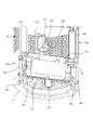
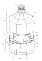
- FIG. 1 is a cross-sectional view showing a lighting device to which the air purifying device according to the embodiment of the present invention is applied.
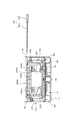
- FIG. 2 is a partially cutaway perspective sectional view showing the internal structure of the lighting device.
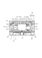
- FIG. 3 is a perspective view showing the structure of an axial fan.
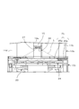
- FIG. 4A is a perspective view showing the structure of the light source unit that irradiates the activation light.
- FIG. 4B is a perspective view showing the illumination range of each of the plurality of LEDs constituting the light source unit.
- FIG. 5 is a perspective view showing a light source unit provided in the lower housing.
- FIG. 6 is a perspective view showing the photocatalyst unit.
- FIG. 1 is a cross-sectional view showing a lighting device to which the air purifying device according to the embodiment of the present invention is applied.
- FIG. 2 is a partially cutaway perspective sectional view showing the internal structure of the lighting device.
- FIG. 3 is a perspective view showing the structure of
- FIG. 7 is a cross-sectional view showing a state immediately before mounting the photocatalyst unit on the housing (lower housing).
- FIG. 8 is a cross-sectional view showing a state immediately after starting mounting of the photocatalyst unit on the housing (lower housing).
- FIG. 9 is a perspective view showing a state immediately after starting mounting of the photocatalyst unit on the housing (lower housing).
- FIG. 10 is a cross-sectional view showing an irradiation state of the photocatalyst unit of the activated light from the light source unit in the housing (lower housing).
- FIG. 11 is a perspective view showing an irradiation state of the photocatalyst unit of the activated light from the light source unit in the housing.
- FIG. 12 shows the irradiation state of the activation light from the back UV-LED (back light source) in the housing (lower housing, middle housing) together with the irradiation state of the activation light from the light source unit. It is sectional drawing which shows.
- FIG. 13 is a perspective view showing an irradiation state of the photocatalyst unit of the activated light from the back UV-LED (back light source) in the housing.
- FIG. 14 is a perspective view showing another arrangement example of the light source unit in the housing (lower housing).
- FIG. 1 is a cross-sectional view showing a lighting device
- FIG. 2 is a partially cutaway perspective cross-sectional view showing the internal structure of the lighting device.
- the housing 10 of the lighting device 100 has a structure in which the upper housing 10a, the middle housing 10b, and the lower housing 10c are vertically connected.
- a base 20 that can be attached to a socket connected to indoor wiring is provided at an end portion of the upper housing 10a that should face upward.
- Each of the lower housing 10c and the middle housing 10b connected to each other has an octagonal square tube shape, and the upper housing 10a has an octagonal square tube shape portion connected to the middle housing 10b toward the base 20.
- the diameter is gradually reduced (see FIGS. 11 and 13 described later together with FIG. 2).
- An intake port 12 is formed at an end portion of the lower housing 10c (housing 10) that should face downward. Further, the side peripheral surface of the inner housing 10b is covered with a panel in which many slits are formed, and many slits of the panel function as an outlet 13.
- the lower housing 10c is provided with an annular lighting cover 11 so as to surround the intake port 12.
- a proximity sensor 30 that outputs a detection signal according to the degree of approach of an object (person) is provided so as to be located at the center of the intake port 12.
- a circuit board 28 is provided at the end of the lower housing 10c where the intake port 12 is formed.
- the circuit board 28 has an annular portion covered by the annular lighting cover 11 and a transverse portion that traverses the inside of the annular portion.
- a plurality of LEDs (light emitting diodes) 29 distributed and arranged as a light source (illumination unit) for illumination are mounted on the annular portion of the circuit board 28.
- a proximity sensor 30 is mounted on the cross-sectional portion of the circuit board 28.
- a pre-filter 18 is provided so as to cover the intake port 12.
- the pre-filter 18 is formed of a relatively coarse flat mesh body that does not significantly obstruct the flow of air sucked from the intake port 12.
- the pre-filter 18 prevents dust, insects, and the like from entering the lower housing 10c (housing 10).
- the lower housing 10c is provided with an axial flow fan 23 so as to face the outlet 12 (pre-filter 18).
- the axial flow fan 23 is configured as shown in FIG.
- the axial fan 23 is arranged between the motor 230, the outer frame 231 surrounding the motor 230, the outer frame 231 and the motor 230, the fan blade 232 rotated by the motor 230, and the motor 230 as the outer frame 231. It has four (plural) connecting frames 233a, 233b, 233c, and 233d to be connected to the above.
- the rotation of the fan blade 232 rotated by the motor 230 draws air into the lower housing 10c (housing 10) from the intake port 12.
- a light source unit 24 and a photocatalyst unit 25 are further provided in the lower housing 10c.
- the light source unit 24 is arranged on the downstream side of the axial flow fan 23 in the direction of the air flow (see the thick dashed arrow in FIG. 1) so as to face the axial flow fan 23, and is a photocatalyst toward the downstream direction of the air flow. Irradiate the activation light of (photocatalyst unit 25). As shown in FIG.
- the light source unit 24 has 12 (3 or more) UV-LEDs (ultraviolet light emitting diodes) 244a to 244d, 245a, each of which irradiates activation light having a predetermined wavelength (for example, 365 nm) in the ultraviolet region. It has ⁇ 245d, 246a ⁇ 246d. These UV-LEDs 244a to 244d, 245a to 245d, and 246a to 246d are mounted on the circuit board 240 so as to be distributed and arranged on one plane SF.
- UV-LEDs ultraviolet light emitting diodes
- the circuit board 240 has an annular outer peripheral ring portion 241 (outer peripheral portion), an annular central ring portion 242 (central portion) arranged inside the outer peripheral ring portion 241, and a central ring portion 242 and an outer peripheral ring portion 241. It has four (plural) connecting arms 243a, 243b, 243c, and 243d that connect with.
- Four UV-LEDs 244a, 244b, 244c, 244d are mounted on the outer ring portion 241 and four UV-LEDs 245a, 245b, 245c, 245d are mounted on the central ring portion 242.
- UV-LED246a is attached to the connecting arm portion 243a
- UV-LED246b is attached to the connecting arm portion 243b
- UV-LED246c is attached to the connecting arm portion 243c
- UV-LED246d is attached to the connecting arm portion 243d.
- activation light (ultraviolet rays) from each of the 12 UV-LEDs 244a to 244d, 245a to 245d, and 246a to 246d distributed and arranged on the plane SF (circuit board 240) as described above.
- the irradiation ranges L4a to L4d, L5a to L5d, and L6a to L6d allow the activation light (ultraviolet rays) to be irradiated to a wider surface facing the light source unit 24.
- the light source unit 24 having the above-mentioned structure is arranged in the lower housing 10c so as to face the axial flow fan 23.
- the outer peripheral ring portion 241 of the circuit board 240 faces the outer frame 231 of the axial flow fan 23
- the central ring portion 242 of the circuit board 240 faces the motor 230 of the axial flow fan 23.
- the connecting arm portion 243a of the circuit board 240 is attached to the connecting arm portion 233a of the axial flow fan 23
- the connecting arm portion 243b of the circuit board 240 is attached to the connecting arm portion 233b of the axial flow fan 23
- the connecting arm portion 243c of the circuit board 240 is the axis.
- the connecting arm portion 243d of the circuit board 240 faces the connecting frame 233c of the flow fan 23, and faces the connecting frame 233d of the axial flow fan 23, respectively.
- the light source unit 24 circuit board 240, UV-LEDs 244a to 246d
- the outer ring portion 241 and the central ring portion 242 and the four connecting arm portions 243a of the circuit board 240 are arranged.
- ⁇ 243d is hidden by the motor 230 of the axial flow fan 23, the outer frame 231 and the four connecting frames 233a to 233d with respect to the air flow generated by the axial flow fan 23.
- the photocatalyst unit 25 arranged on the downstream side in the direction of the air flow facing the light source unit 24 (circuit board 240, UV-LEDs 244a to 246d) is configured as shown in FIG.
- the photocatalyst unit 25 has a structure in which, for example, a photocatalyst body 25a in which a photocatalyst (for example, titanium dioxide) is supported on a flat metal body is supported in a plane by a support frame 25b.
- the metal flat network used for the photocatalyst body 25a is thin, for example, has a predetermined thickness of 1 mm or less, and has a finer mesh than the pre-filter 18.
- a slit extending in the lateral direction (parallel to the surface of the circuit board 240 of the light source unit 24) as an insertion port of the photocatalyst unit 25 is provided in the portion of the side surface of the lower housing 10c near the middle housing 10b.
- the holes 16 are formed.
- the flat plate-shaped photocatalyst unit 25 is inserted into the lower housing 10c (housing 10) through the slit hole 16 as shown in FIGS. 7, 8 and 9, and the light source unit 24 (as shown in FIG. 10). It is set so as to face the circuit board 240, UV-LEDs 244a to 246d).
- the photocatalyst unit 25 can be taken out from the lower housing 10c (housing 10) through the slit hole 16. With the photocatalyst unit 25 set in the lower housing 10c (housing 10) as shown in FIG. 10, activation light is emitted from each UV-LEDs 244a to 246d of the light source unit 24 into a flat net-like photocatalyst of the photocatalyst unit 25.
- the body 25a is irradiated.
- the irradiation range L4a to L6d (see FIG. 4B) of the activation light (ultraviolet rays) from the 12 UV-LEDs 244a to 246d are, for example, in FIG.
- the irradiation range L4a of the UV-LED244a and the irradiation range L5a of the UV-LED245a are covered substantially evenly.
- a rectangular opening 17 for forming an air flow to the middle housing 10b is provided on the upper surface of the lower housing 10c (the end surface opposite to the intake port 12). It is formed.
- the middle housing 10b has four columns 14a for securing a space as the middle housing 10b between the peripheral portion of the opening 17 and the upper housing 10a. 14b, 14c, 14d (see FIGS. 1 and 2 for the support column 14a) are provided. Then, by covering the circumferences of these four columns 14a, 14b, 14c, and 14d with panels having many slits as described above, the middle housing 10b having the outlet 13 formed on the side peripheral surface is configured. (See FIGS. 1 and 2).
- the middle housing 10b is provided with a circuit board 15 having both ends fixed to the columns 14a and 14c, as shown in FIG. 1 as a cross section and in FIG. 2 as a partially cutaway perspective section. ..
- the circuit board 15 has a back UV-LED 26 (a back UV-LED 26) that irradiates the photocatalyst body 25a (photocatalyst unit 25) with activation light from the opposite side of the light source unit 24, that is, from the downstream side of the photocatalyst unit 25 in the direction of air flow. (Back light source) is installed.
- the irradiation range L of the activation light from the back UV-LED 26 is set so as to cover the photocatalyst body 25a more widely as shown in FIGS.
- the activation light from the back UV-LED 26 is set to a wavelength different from the wavelength of the activation light (ultraviolet rays) from each of the UV-LEDs 244a to 246d of the light source unit 24. Specifically, it is set to a wavelength shorter than the wavelength of the activation light (for example, 365 nm) from each UV-LED 244a to 246d (for example, 275 nm: deep ultraviolet region).
- a light guide plate 31 (light guide body) made of acrylic resin or the like is described above in a predetermined portion near the middle housing 10b of the lower housing 10c. It is provided so as to face the photocatalyst body 25a (photocatalyst unit 25) through the rectangular opening 17.
- One end surface 31a of the light guide plate 31 is exposed from the side surface of the lower housing 10c (housing 10).
- the light guide plate 31 receives the activation light from the light source unit 24 passing through the flat mesh photocatalyst body 25a and propagates to the end face 31a.
- the brightness of the end face 31a of the light guide plate 31 may change depending on the amount of light propagated.
- an optical sensor 27 is further attached to the circuit board 15 on which the above-mentioned back UV-LED 26 is mounted.
- the optical sensor 27 is arranged at a position where it can receive the activation light from the light source unit 24 passing through the flat mesh photocatalyst body 25a, and outputs a detection signal according to the amount of received light.
- the upper housing 10a is provided with a power supply circuit 21 that converts alternating current electricity introduced through the base 20 into predetermined direct current electricity.
- a control circuit board 22 is provided at a portion connected to the upper housing 10a of the middle housing 10b.
- the direct current electricity from the power supply circuit 21 is transmitted to the plurality of lighting LEDs 29 mounted on the circuit board 28, the axial flow fan 23, and the 12 UV-LEDs 244a mounted on the circuit board 240 via the control circuit board 22. It is supplied to ⁇ 246d (light source unit 24) and the back UV-LED 26 mounted on the circuit board 15.
- This control circuit is a portion that controls lighting of a plurality of LEDs 29 for lighting based on a detection signal from the proximity sensor 30, and a lighting mode of the plurality of LEDs 29 (illuminating unit) based on a detection signal from the optical sensor 27.
- a portion (illumination control unit) for controlling (illumination light irradiation mode) is included.
- the lighting device 100 as described above is attached to the ceiling of the room (for example, a toilet) by attaching the base 20 to the socket installed on the ceiling. In this state, when the lighting switch is turned on, power is supplied to each part, and the lighting device 100 (air purifying device) is controlled by the control circuit configured on the control circuit board 22.
- the control circuit configured on the control circuit board 22.
- activation light (ultraviolet rays) is emitted from each of the UV-LEDs 244a to 246d of the light source unit 24, and activation light (deep ultraviolet rays) is emitted from the back UV-LED 26.
- the switch is on, the operating state of the axial flow fan 23 and the irradiation state of the activation light from the UV-LEDs 244a to 246d of the light source unit 24 and the back UV-LED 26 are maintained.
- the air in the room is purified as described later.
- a plurality of lighting LEDs 29 are turned on based on the detection signal from the proximity sensor 30 that detects the person, and the room is illuminated. ..
- the photocatalyst for example, titanium dioxide
- the photocatalyst body 25a Upon receiving this activation light (ultraviolet rays), the photocatalyst (for example, titanium dioxide) on the surface of the photocatalyst body 25a is activated to develop a strong oxidizing power, and organic substances in the air flowing in contact with the photocatalyst are decomposed. ..
- the air passing through the flat net-like photocatalyst body 25a while in contact with the photocatalyst is purified by deodorization, sterilization, etc., and the purified air is blown out from the outlet 13 through the inner housing 10b. Will be done.
- the indoor air is gradually purified by continuously drawing the indoor air into the housing 10, purifying the air, and blowing out the purified air. The condition of the clean air is maintained.
- the activation light deep ultraviolet light having a wavelength shorter than the wavelength (for example, 275 nm) of the activation light from the UV-LEDs 244a to 246d of the light source unit 24 described above from the back UV-LED 26.
- the air is purified due to the activation of the opposite surface of the photocatalyst body 25a, and the air is further purified by the action peculiar to the activation light having a short wavelength thereof.
- bacteria and viruses contained in the air that has passed through the flat net-like photocatalyst 25a are purified. In this way, air is blown into the room from the outlet 13 while receiving an additional cleaning action by the activation light from the back UV-LED 26, and the air in the room is further cleaned.
- the axial flow fan 23 arranged to face the intake port 12 positively moves from the intake port 12 into the housing 10 (lower housing 10c). Air is drawn into the air, and the air flow is formed so as to sequentially pass through the light source unit 24 and the photocatalyst unit 25 (photocatalyst body 25a) and be blown out from the air outlet 13. As a result, air can be efficiently drawn into the housing 10 and the photocatalyst body 25a can efficiently purify the air.
- the intake port 12 is formed at the end of the lower housing 10c that should face downward, when the lighting device 100 (air purifier) is attached to the ceiling or the like in the room, the intake port 12 that faces downward thereof. It is possible to efficiently draw in a wider range of air in the room.
- the photocatalyst body 25a of the photocatalyst unit 25 is formed in a flat mesh pattern (see FIG. 6), the area of the photocatalyst body 25a exposed to air can be increased, and the air can be efficiently purified. can. In addition, the photocatalyst body 25a can be made thinner.
- the 12 UV-LEDs 244a to 246d of the light source unit 24 are distributed and arranged on the plane SF facing the axial fan 23, the 12 UV-LEDs 244a to 246d are distributed by the air flow generated by the axial fan 23. It can be cooled efficiently. As a result, deterioration of each UV-LED 244a to 244d due to heat generation can be prevented and the life thereof can be extended. Further, the irradiation ranges LA4a to L6d of the activation light from the 12 UV-LEDs 244a to 246d dispersedly arranged on the plane SF cover the flat net-like photocatalyst 25a arranged opposite to the light source unit 24 substantially evenly. (See FIG. 11), so that the activation light can be effectively applied to the photocatalyst 25a.
- the outer ring portion 241 and the central ring portion 242 of the circuit board 240 of the light source unit 24 and the four connecting arm portions 243a to 243d are together with the 12 UV-LEDs 244a to 244d (light source unit 24) mounted on them.
- the air flow generated by the axial fan 23 is hidden by the motor 230 of the axial fan 23, the outer frame 231 and the four connecting frames 233a to 233d. Therefore, the turbulence of the generated air flow can be reduced.
- the wind pressure drop (pressure loss) caused by the circuit board 240 (light source unit 24: 12 UV-LEDs 244a to 246d) arranged to face the axial flow motor 23 is prevented, and the wind noise is reduced. Can be done.
- the amount of activated light substantially received by the photocatalyst body 25a due to the dust or the like is reduced, and the function of air purification of the photocatalyst is also reduced. As a result, the efficiency of air purification is further reduced.
- the amount of activated light emitted from the light source unit 24 and passing through the flat-net-like photocatalyst body 25a changes according to the degree of clogging of the photocatalyst body 25a, and at the same time, is incident on the light guide plate 31.
- the amount of light emitted also changes.
- the brightness of the end face 31a exposed from the housing 10 (lower housing 10c) of the light guide plate 31 changes.
- the degree of clogging of the photocatalyst body 25a increases, the brightness of the end surface 31a of the light guide plate 31 decreases.
- the user of the lighting device 100 has a degree of clogging of the flat mesh photocatalyst body 25a based on the brightness of the end face 31a (the degree of dust and the like adhering to the photocatalyst body 25a). Including) can be judged. If it is determined that the degree of clogging is large, the photocatalyst unit 25 (photocatalyst body 25a) can be used normally again by pulling out the photocatalyst unit 25 from the housing 10 (lower housing 10c) and cleaning it. Will be able to.
- the amount of activation light that is irradiated from the light source unit 24 and passes through the flat-net-like photocatalyst body 25a as described above changes depending on the degree of clogging of the photocatalyst body 25a.
- the amount of light received by the optical sensor 27 changes, and the detection signal of the optical sensor 27 changes accordingly.
- the control circuit control circuit board 22
- the detection signal from the optical sensor 27 indicates a decrease in the amount of light received. It is lit in a mode different from the mode of immediate lighting (illumination mode of illumination light).
- the brightness can be gradually increased over a certain period of time (for example, several seconds), or the light can be turned on after repeating blinking for a certain period of time.
- the user can determine the degree of clogging of the flat mesh photocatalyst body 25a (including the degree of dust and the like adhering to the photocatalyst body 25a) based on the lighting mode of the plurality of LEDs 29 for lighting. ..
- the processing of the control circuit based on the detection signal from the optical sensor 27 is not limited to the above-mentioned one.
- a separately provided alarm lamp can be turned on.
- an alarm signal can be transmitted to an external device (for example, a user's smartphone) based on the detection signal.
- the outer ring portion 241 and the central ring portion 242 of the circuit board 240 of the light source unit 24 and the four connecting arm portions 243a to 243d are attached to the twelve UV-LEDs 244a to 244d (light source). Together with the unit 24), the air flow generated by the axial fan 23 is hidden by the motor 230 of the axial fan 23, the outer frame 231 and the four connecting frames 233a to 233d.
- the circuit board 240 can also be arranged, for example, as shown in FIG.
- the outer peripheral ring portion 241 of the circuit board 240 faces the outer frame 231 of the axial flow fan 23, and the central ring portion 242 of the circuit board 240 faces the motor 230 of the axial flow fan 23.
- none of the connecting arm portions 243a to 243d of the circuit board 240 faces any of the connecting frames 233a to 233d of the axial flow fan 23. Even in this case, all 12 UV-LEDs 244a to 246d can be efficiently cooled by the air flow generated by the axial fan 23.
- the outer peripheral ring portion 241 and the central ring portion 242 of the circuit board 240, together with the UV-LEDs 244a to 244d and 245a-245d mounted therein, are of the axial flow fan 23 with respect to the air flow generated by the axial flow fan 23. It will be hidden behind the motor 230 and the outer frame 231. As a result, the turbulence of the air flow generated by the axial flow fan 23 can be reduced to some extent.
- UV-LEDs 244a to 246 In the case of the arrangement as shown in FIG. 14, of the 12 UV-LEDs 244a to 246, eight UV-LEDs 244a to 244d and 245a to 245d, which are two-thirds of the twelve UV-LEDs 244a to 246, are motors of the axial fan 23. It was arranged corresponding to 230 and the outer frame 231. From the viewpoint of reducing the turbulence of the air flow generated by the axial flow motor fan 23, more than half (UV-LEDs) of the plurality (3 or more) light emitting elements (UV-LEDs) constituting the light source unit 24 (in the above example). In this case, it is preferable that six or more light emitting elements (UV-LEDs) are arranged so as to face any of the motor 230 of the axial flow fan 23, the outer frame 231 and the plurality of connecting frames 233a to 233d.
- UV-LEDs six or more light emitting elements
- the photocatalyst body 25a has a structure in which a photocatalyst (for example, titanium dioxide) is supported on a flat net body, but the structure that allows air to pass through is not limited to using the flat net body.
- the photocatalyst body 25a can be formed by supporting a photocatalyst on a punching metal, an expanded metal, or another plate having a porous structure.
- the photocatalyst body 25a is not particularly limited as long as it has a structure exposed to air sucked from the intake port 12 by the axial fan 23.
- the embodiment of the light source unit 24 having three or more UV-LEDs distributed and arranged on the plane SF facing the axial flow fan 23 is a preferred embodiment, and is not limited to this in the present invention.
- the air purifying device according to the above-described embodiment has been applied to the lighting device 100, but is not limited thereto. It may be an air purifier alone that does not have a lighting unit (plurality of LEDs 29), or it may be applied to other devices.
- the configuration of the housing 10 is not limited to that described above (see FIG. 1).
- the vertical ratios of the three parts of the housing 10 may be different from those described above (see FIG. 1).
- the housing 10 may be composed of two or four or more parts, or may be a single one.
Abstract
本発明は、筐体内に効率的に空気を引き込んで、効率的に空気の清浄化が可能な空気清浄装置を提供するものである。 本発明に係る空気清浄装置は、吸気口12と吹出口13とを有する筐体10と、吸気口12に対向して配置され、筐体10内において吸気口12から引き込まれて吹出口13から吹き出される空気流を生成する軸流ファン23と、前記空気流の方向の軸流ファン23の下流側に配置され、活性化光を前記空気流の下流方向に照射する光源ユニット24と、前記空気流の方向の光源ユニット24の下流側に配置され、光源ユニット24からの活性化光を受けて活性化する光触媒体25aと、を有する構成となる。
Description
本発明は、光触媒を用いて空気を浄化(脱臭等)する空気清浄装置に関する。
従来、特許文献1に開示された空気清浄機能を有する照明装置(空気清浄装置)が知られている。この照明装置では、筐体の側面に形成された吸気口から前記筐体の下方を向くべき端部に形成された吹出口に至る通風路が形成されており、前記吹出口に対向してファンが設けられている。このファンが動作すると、通風路中の空気が吹出口から吹き出され、それに伴って吸気口から空気が筐体内に引き込まれて、吸気口から吹出口に至る通風路中に空気流が形成される。通風路中には、空気流の方向における前記ファンの上流側に光触媒塗布体が設けられ、その光触媒塗布体の更に上流側に活性化光を照射する活性化光源が設けられている。光触媒塗布体は、空気流に向かって漸次細くなる円錐体の表面に光触媒が塗布されたもので、その円錐体の頂部に対向して前記活性化光源が配置されている。
また、筐体の下方を向くべき端部に形成された前記吹出口の周りには、複数の発光素子で構成される照明部が設けられている。前記筐体の前記吹出口と逆側の端部には口金が設けられており、この口金が、屋内配線に接続されたソケットに結合される。筐体内には、口金を介して導入される交流電気を所定の直流電気に変換し、その直流電気を前記照明部、活性化光源、ファンに供給するACアダプタが設けられている。
このような照明装置は、例えば、室内の天井に設けられたソケットに口金を結合させて使用される。口金がソケットに結合した状態で、給電される照明部からの照明光によってその部屋内が照明されるとともに、給電されるファンが動作する。このファンの動作により、室内の空気が吸気口から筐体内に引き込まれつつ、筐体内の通風路を通る空気が吹出口から下方に向けて吹き出される。通風路中では、活性化光源からの活性化光の照射を受ける光触媒塗布体の光触媒が活性化されており、その活性化された光触媒に接触しながら流れる空気の脱臭、殺菌等が行われる。そして、その脱臭、殺菌がなされた空気が吹出口から下方に向けて吹き出される。その結果、室内の空気が徐々に浄化(脱臭、殺菌等)される。
上述したような空気清浄機能を有する照明装置では、吹出口に対向して設けられたファンがその吹出口から筐体内の空気を吹き出すことにより、その結果として、吸気口から筐体内に空気が引き込まれて通風路に空気流が生ずる。このため、吸気口から効率的に空気の引き込みができず、効率的な空気の清浄化が難しい。
本発明は、このような事情に鑑みてなされたもので、筐体内に効率的に空気を引き込んで、効率的に空気の清浄化が可能な空気清浄装置を提供するものである。
本発明に係る空気清浄装置は、吸気口と吹出口とを有する筐体と、前記吸気口に対向して配置され、前記筐体内において前記吸気口から引き込まれて前記吹出口から吹き出される空気流を生成する軸流ファンと、前記空気流の方向の前記軸流ファンの下流側に配置され、活性化光を前記空気流の下流方向に照射する光源ユニットと、前記空気流の方向の前記光源ユニットの下流側に配置され、前記光源ユニットからの活性化光を受けて活性化する光触媒体と、を有する構成となる。
このような構成により、吸気口に対向して配置される軸流ファンの動作により前記吸気口から筐体内に積極的に空気が引き込まれる。そして、筐体内において、前記吸気口から引き込まれて吹出口から吹き出される空気流が形成される。空気流の方向の前記軸流ファンの下流側に配置された光源ユニットからその空気流の方向の更に下流方向に配置された光触媒体に活性化光が照射される。活性化光を受けることにより活性化される光触媒体に接触しながら流れる空気が、その活性化される光触媒によって脱臭等、清浄化され、その清浄化された空気が吹出口から吹き出される。
本発明に係る空気清浄装置において、前記吸気口は、前記筐体の下方を向くべき端部に形成され、前記吹出口は、前記筐体の側面に形成された、構成とすることができる。
このような構成により、空気清浄装置を室内の高い位置に設置すると、下方に向く吸気口から、室内のより広い範囲の空気を効率的に引き込むことができる。
本発明に係る空気清浄装置において、前記光触媒体は、平網状に形成され、前記空気流が通過するように配置された、構成とすることができる。
このような構成により、光触媒体の空気流にさらされる面積を大きくすることができるとともに、光触媒体の薄型化を図ることができる。
本発明に係る空気清浄装置において、前記光源ユニットは、前記軸流ファンに対向する平面上に分散配置された3以上の発光素子を有する、構成とすることができる。
このような構成により、軸流ファンに対向する平面上に分散配置された3以上の発光素子を有する光源ユニットを当該軸流ファンにより生ずる空気流によって効果的に冷却することができるとともに、その平面上に分散配置された3以上の発光素子からの活性化光を平網状の光触媒体に効果的にあてることができる。
本発明に係る空気清浄装置において、前記軸流ファンは、モータと、該モータを囲む外フレームと、該外フレームと前記モータとの間に配置され、前記モータによって回転されるファンブレードと、前記モータを前記外フレームに結合させる複数の連結フレームと、を有し、前記3以上の発光素子の半数以上は、前記軸流ファンの前記モータ、前記外フレーム及び前記複数の連結フレームのいずれかに対向して配置された、構成とすることができる。
このような構成により、軸流ファンに対向した平面上に配置される3以上の発光素子の半数以上が、軸流ファンの回転するファンブレードによって発生する空気流に対して隠れるようになる。このため、その発生する空気流の乱れを低減させることができる。
本発明に係る空気清浄装置において、前記3以上の発光素子のそれぞれは、基板に装着された発光ダイオードであって、前記基板は、前記モータに対向する環状の中央部と、前記外フレームに対向する環状の外周部と、前記中央部と前記外周部とを結合する複数の連結腕部とを含む、構成とすることができる。
このような構成により、平面上に配置される光源ユニットとしての3以上の発光ダイオードが装着された基板のうちの少なくとも中央部及び外周部が、軸流ファンの回転するファンブレードによって発生する空気流に対して、その軸流ファンのモータ及び外フレームに隠れるようになる。このため、その発生する空気流の乱れを低減させることができる。
本発明に係る空気清浄装置において、前記複数の連結腕部のぞれぞれは、前記軸流ファンの前記複数の連結フレームのいずれかに対向する、構成とすることができる。
このような構成により、平面上に配置される光源ユニットとしての3以上の発光ダイオードが装着された基板の中央部、外周部及び複数の連結腕部が、軸流ファンの回転するファンブレードによって発生する空気流に対して、その軸流ファンのモータ、外フレーム及び複数の連結フレームに隠れるようになる。このため、その発生する空気流の乱れを更に低減させることができる。
本発明に係る空気清浄装置において、前記光触媒体を通過する前記光源ユニットからの活性化光を受けて前記筐体から露出させた端面まで伝搬させる導光体を有する、構成とすることができる。
このような構成により、平網状の光触媒体の目詰まりの具合に応じて、光源ユニットからの活性化光の前記光触媒体(平網状)を通過する量が変化するので、筐体から露出する導光体の端面の明るさに基づいて、平網状の光触媒体の目詰まりの程度を判断することができる。
本発明に係る空気清浄装置において、前記光触媒体を通過する前記光源ユニットからの活性化光の受光量に応じた検出信号を出力する光センサを有する、構成とすることができる。
このような構成により、平網状の光触媒体の目詰まりに応じて、光源ユニットからの活性化光の前記光触媒体(平網状)を通過する量が変化するので、光センサからの出力信号に基づいて、平網状の光触媒体の目詰まりの程度を判断することができる。
本発明に係る空気清浄装置において、前記筐体の外方に照明光を照射する照明部を有し、前記光センサからの検出信号に基づいて照明光の照射態様を制御する照明制御部を有する、構成とすることができる。
このような構成により、照明部の照明態様に基づいて平網状の光触媒体の目詰まりの程度を判断することができる。
本発明に係る空気清浄装置において、前記空気流の方向の前記光触媒体の下流側に配置され、活性化光を前記光触媒体に照射する背後光源を有する、構成とすることができる。
このような構成により、光源ユニットが対向しない平網状の光触媒体の面に対して背後光源からの活性化光が照射されるので、平網状の光触媒体の活性化の促進を図ることができる。
本発明に係る空気清浄装置において、前記光源ユニットから照射される前記活性化光の波長と、前記背後光源から照射される活性化光の波長とは異なる、構成とすることができる。
このような構成により、背後光源から照射される活性化光により、光触媒体の活性化以外に、その波長に応じた空気の清浄作用を得ることができる。
本発明に係る空気清浄装置によれば、吸気口に対向して配置される軸流ファンの動作により前記吸気口から筐体内に積極的に空気が引き込まれ、空気流が光源ユニット、光触媒体を順次通過して吹出口から吹き出されるように形成されるので、筐体内に効率的に空気を引き込んで、光触媒体による効率的な空気の清浄化が可能になる。
本発明の実施の形態について図面を用いて説明する。
本発明の実施の一形態に係る空気清浄装置が適用される照明装置は、図1及び図2に示すように構成される。図1は照明装置を示す断面図であり、図2は前記照明装置の内部の構造を示す一部切り欠き斜視断面図である。
図1及び図2において、照明装置100(空気清浄装置)の筐体10は、上筐体10a、中筐体10b、及び下筐体10cが縦方向に連結した構造となっている。上筐体10aの上方を向くべき端部には、屋内配線に接続されるソケットに装着可能な口金20が設けられている。相互に連結する下筐体10c及び中筐体10bのそれぞれは、八角の角筒形状であり、上筐体10aは、中筐体10bに連結する八角の角筒形状部分から口金20に向けて徐々に縮径する形状となっている(図2とともに後述する図11、図13参照)。口金20を屋内配線に接続されるソケットに装着することにより、この照明装置100(空気清浄装置)は電力供給を受けることができる。下筐体10c(筐体10)の下方を向くべき端部には吸気口12が形成されている。また、中筐体10bの側周面は多くのスリットの形成されたパネルで覆われており、そのパネルの多くのスリットが吹出口13として機能する。
下筐体10cには、吸気口12を囲むように環状の照明カバー11が設けられている。吸気口12の中央部に位置するように、物体(人)の接近の度合いに応じた検出信号を出力する近接センサ30が設けられている。また、下筐体10cの吸気口12が形成される端部には、回路基板28が設けられている。回路基板28は、環状の照明カバー11に覆われる環状部分と、その環状部分の内側を横断する横断部分とを有する。回路基板28の環状部分には、照明用の光源(照明部)として分散配置される複数のLED(発光ダイオード)29が装着されている。回路基板28の横断部分には近接センサ30が装着されている。また、吸気口12を覆うようにプレフィルタ18が設けられている。このプレフィルタ18は、後述するように吸気口12から吸引される空気の流れを大きく妨げることのない比較的目の粗い平網体で形成される。このプレフィルタ18によって埃や虫等が下筐体10c(筐体10)内に進入することが防止される。
下筐体10cには、軸流ファン23が吹出口12(プレフィルタ18)に対向して配置されるように設けられている。軸流ファン23は、図3に示すように構成される。この軸流ファン23は、モータ230と、モータ230を囲む外フレーム231と、外フレーム231とモータ230との間に配置され、モータ230によって回転されるファンブレード232と、モータ230を外フレーム231に連結させる4つ(複数)の連結フレーム233a、233b、233c、233dとを有している。モータ230により回転されるファンブレード232のその回転により空気が吸気口12から下筐体10c(筐体10)内に引き込まれる。筐体10においては、下筐体10cの吸気口12から引き込まれて、下筐体10cから中筐体10bを通り、中筐体10bの吹出口13から吹き出される空気流(図1における破線太矢印参照)が形成される。
下筐体10c内には、更に、光源ユニット24及び光触媒ユニット25が設けられている。光源ユニット24は、空気流の方向(図1における破線太矢印参照)の軸流ファン23の下流側に、その軸流ファン23に対向するように配置され、空気流の下流方向に向けて光触媒(光触媒ユニット25)の活性化光を照射する。光源ユニット24は、図4Aに示すように、それぞれ紫外線域の所定波長(例えば、365nm)の活性化光を照射する12個(3以上)のUV-LED(紫外線発光ダイオード)244a~244d、245a~245d、246a~246dを有する。これらのUV-LED244a~244d、245a~245d、246a~246dは、1つの平面SF上に分散配置されるように、回路基板240上に装着される。
回路基板240は、円環状の外周環部241(外周部)と、外周環部241の内側に配置される円環状の中央環部242(中央部)と、中央環部242と外周環部241とを結合する4つ(複数)の連結腕部243a、243b、243c、243dとを有している。外周環部241に4つのUV-LED244a、244b、244c、244dが装着され、中央環部242に4つのUV-LED245a、245b、245c、245dが装着されている。また、連結腕部243aにUV-LED246aが、連結腕部243bにUV-LED246bが、連結腕部243cにUV-LED246cが、連結腕部243dにUV-LED246dが、それぞれ装着されている。図4Bに示すように、前述したように平面SF(回路基板240)上に分散配置される12個のUV-LED244a~244d、245a~245d、246a~246dそれぞれからの活性化光(紫外線)の照射範囲L4a~L4d、L5a~L5d、L6a~L6dにより、この光源ユニット24に対向するより広い面に対して活性化光(紫外線)を照射することができる。
前述した構造の光源ユニット24は、図5に示すように、下筐体10c内において軸流ファン23に対向して配置される。具体的には、回路基板240の外周環部241が軸流ファン23の外フレーム231に対向し、回路基板240の中央環部242が軸流ファン23のモータ230に対向する。また、回路基板240の連結腕部243aが軸流ファン23の連結フレーム233aに、回路基板240の連結腕部243bが軸流ファン23の連結フレーム233bに、回路基板240の連結腕部243cが軸流ファン23の連結フレーム233cに、回路基板240の連結腕部243dが軸流ファン23の連結フレーム233dに、それぞれ対向する。光源ユニット24(回路基板240、UV-LED244a~246d)がこのように軸流ファン23に対向配置されることにより、回路基板240の外周環部241、中央環部242及び4つの連結腕部243a~243dが、軸流ファン23によって発生する空気流に対して、軸流ファン23のモータ230、外フレーム231及び4つの連結フレーム233a~233dに隠れるようになる。
光源ユニット24(回路基板240、UV-LED244a~246d)に対向して空気流の方向の下流側に配置される光触媒ユニット25は、図6に示すように構成される。この光触媒ユニット25は、例えば金属製の平網体に光触媒(例えば、二酸化チタン)が担持されてなる光触媒体25aが支持フレーム25bによって平面状に支持された構造となっている。この光触媒体25aに用いられる金属製の平網体は、薄く、例えば、1mm以下の所定の厚さとなり、プレフィルタ18より細かい網目を有する。
下筐体10cの側面の中筐体10b寄りの部分には、図5に示すように、光触媒ユニット25の挿入口として、横方向(光源ユニット24の回路基板240の面に平行)に延びるスリット孔16が形成されている。平板状の光触媒ユニット25は、図7、図8及び図9に示すように、スリット孔16から下筐体10c(筐体10)内に挿入され、図10に示すように、光源ユニット24(回路基板240、UV-LED244a~246d)に対向するようにセットされる。なお、光触媒ユニット25は、スリット孔16を通して下筐体10c(筐体10)内から取り出し可能である。光触媒ユニット25が図10に示すように下筐体10c(筐体10)内にセットされた状態で、光源ユニット24の各UV-LED244a~246dから活性化光が光触媒ユニット25の平網状の光触媒体25aに照射される。12個のUV-LED244a~246dからの活性化光(紫外線)の照射範囲L4a~L6d(図4B参照)は、例えば、図10において、UV-LED244aの照射範囲L4a、UV-LED245aの照射範囲L5a、UV-LED245bの照射範囲L5b、UV-LED245cの照射範囲L5c、UV-LED244cの照射範囲L4cのように、また、図11に示すように、平網状の光触媒体25aを略満遍なくカバーする。
また、図5及び図9に示すように、下筐体10cの上面(吸気口12と逆側の端面)には、中筐体10bへの空気流を形成するための矩形状の開口17が形成されている。そして、中筐体10bには、更に、図11に示すように、開口17の周囲部分と上筐体10aとの間に、中筐体10bとしての空間を確保するための4つの支柱14a、14b、14c、14d(支柱14aについては図1及び図2参照)が設けられている。そして、これら4つの支柱14a、14b、14c、14dの周りを前述したように多くのスリットの形成されたパネルで覆うことにより、吹出口13が側周面に形成された中筐体10bが構成される(図1及び図2参照)。
中筐体10bには、図1に断面として、また、図2に一部切り欠き斜視断面として示されるように、両端が支柱14aと支柱14cとに固定された回路基板15が設けられている。回路基板15には、光源ユニット24とは逆側から、すなわち、空気流の方向の光触媒ユニット25の下流側から、光触媒体25a(光触媒ユニット25)に活性化光を照射する背後UV-LED26(背後光源)が装着されている。この背後UV-LED26からの活性化光の照射範囲Lは、図12及び図13に示すように、光触媒体25aをより広く覆うように設定される。また、背後UV-LED26からの活性化光は、光源ユニット24の各UV-LED244a~246dからの活性化光(紫外線)の波長とは異なる波長に設定される。具体的には、各UV-LED244a~246dからの活性化光(例えば、365nm)の波長より短い波長(例えば、275nm:深紫外線域)に設定される。
下筐体10cの中筐体10b寄りの所定部分には、図5、図9、図11及び図13に示すように、アクリル樹脂等で形成された導光板31(導光体)が前述した矩形状の開口17を通して光触媒体25a(光触媒ユニット25)に臨むように設けられている。導光板31の一方の端面31aは、下筐体10c(筐体10)の側面から露出している。導光板31は、平網状の光触媒体25aを通過する光源ユニット24からの活性化光を受けて端面31aまで伝搬させる。導光板31の端面31aの明るさは、伝搬される光の量に応じて変化し得る。
また、図1、図2及び図12に示すように、前述した背後UV-LED26が装着された回路基板15には、更に、光センサ27が取り付けられている。この光センサ27は、平網状の光触媒体25aを通過する光源ユニット24からの活性化光を受けることができる位置に配置され、その受光量に応じた検出信号を出力する。
図1に示すように、上筐体10aには、口金20を介して導入される交流電気を所定の直流電気に変換する電源回路21が設けられている。また、中筐体10bの上筐体10aに結合する部分には、制御用回路基板22が設けられている。電源回路21からの直流電気は、制御用回路基板22を介して、回路基板28に装着された照明用の複数のLED29、軸流ファン23、回路基板240に装着された12個のUV-LED244a~246d(光源ユニット24)、及び回基板15に装着された背後UV-LED26に供給される。また、回路基板28に装着された近接センサ30及び回路基板15に装着された光センサ27それぞれからの検出信号は、制御用回路基板22に構成される制御回路に供給される。この制御回路は、近接センサ30からの検出信号に基づいて照明用の複数のLED29の点灯制御を行う部分、また、光センサ27からの検出信号に基づいて複数のLED29(照明部)の点灯態様(照明光の照射態様)を制御する部分(照明制御部)を含む。
上述したような照明装置100は、室内(例えば、トイレ)の天井に設置されたソケットに口金20を装着することにより、その天井に取り付けられる。この状態で、照明用のスイッチのオン操作がなされると、各部への給電が行われるとともに、制御用回路基板22に構成される制御回路による制御のもと、照明装置100(空気清浄装置)は次のように動作する。
軸流ファン23が作動するとともに、光源ユニット24の各UV-LED244a~246dから活性化光(紫外線)が、背後UV-LED26から活性化光(深紫外線)がそれぞれ照射される。以後、前記スイッチがオン状態である間、軸流ファン23の作動状態、光源ユニット24の各UV-LED244a~246d及び背後UV-LED26からの活性化光の照射状態が維持される。これにより、後述するように前記室内の空気が清浄化される。このようにして空気が清浄化される前記室内に人が進入すると、その人を感知する近接センサ30からの検出信号に基づいて、照明用の複数のLED29が点灯し、前記室内が照明なされる。
下筐体10cにおいて吸気口12に対向して配置される軸流ファン23の動作により、その吸気口12から筐体10(下筐体10c)内に積極的に空気が引き込まれる。そして、筐体10(下筐体10c、中筐体10b)内において、吸気口12から引き込まれて吹出口13から吹き出していく空気流が形成される(図1に示す破線太矢印参照)。このような空気流が形成される状態で、光源ユニット24の12個のUV-LED244a~246dからの活性化光(紫外線)が光触媒ユニット25の平網状の光触媒体25aに照射される(図10、図11参照)。この活性化光(紫外線)を受けることにより光触媒体25a表面の光触媒(例えば、二酸化チタン)が活性化して強力な酸化力を発現し、その光触媒に接触しながら流れる空気中の有機物が分解される。それにより、光触媒に接触しながら平網状の光触媒体25aを通過する空気が、脱臭、除菌等、清浄化され、その清浄化された空気が、中筐体10bを通って吹出口13から吹き出される。このような室内の空気の筐体10内への引き込み、その空気の清浄化、そして、その清浄化された空気の吹き出しが継続的に行われることにより、室内の空気が徐々に清浄化されていき、その清浄な空気の状態が維持される。
また、同時に、背後UV-LED26から、前述した光源ユニット24の各UV-LED244a~246dからの活性化光の波長(例えば、365nm)より短い波長(例えば、275nm)の活性化光(深紫外線)が、光触媒体25aの逆側の面に照射される。これにより、光触媒体25aの逆側の面の活性化に起因した空気の清浄化とともに、その短い波長の活性化光特有の作用により空気の更なる清浄化が行われる。例えば、平網状の光触媒体25aを通過した空気中に含まれる細菌やウィルスについての浄化がなされる。このように背後UV-LED26からの活性化光による追加的な清浄化作用を受けつつ空気が吹出口13から室内に吹き出され、その室内の空気の更なる清浄化が図られる。
上述したような照明装置100(空気清浄装置)によれば、吸気口12に対向して配置される軸流ファン23の動作により吸気口12から筐体10(下筐体10c)内に積極的に空気が引き込まれ、空気流が、光源ユニット24、光触媒ユニット25(光触媒体25a)を順次通過して吹出口13から吹き出されるように形成される。これにより、筐体10内に効率的に空気を引き込んで、光触媒体25aによる効率的な空気の清浄化が可能になる。特に、吸気口12が下筐体10cの下方を向くべき端部に形成されているので、照明装置100(空気清浄装置)を室内の天井等に取り付けた場合に、その下方を向く吸気口12から室内のより広い範囲の空気を効率的に引き込むことができる。
また、光触媒ユニット25の光触媒体25aが平網状に形成されているので(図6参照)、その光触媒体25aの空気にさらされる面積を大きくすることができ、空気を効率的に浄化することができる。また、光触媒体25aの薄型化を図ることができる。
光源ユニット24の12個のUV-LED244a~246dが軸流ファン23に対向する平面SF上に分散配置されているので、それら12個のUV-LED244a~246dを軸流ファン23により生ずる空気流によって効率的に冷却することができる。その結果、各UV-LED244a~244dの発熱による劣化を防止してその寿命を延ばすことができる。また、平面SF上に分散配置された12個のUV-LED244a~246dからの活性化光の照射範囲LA4a~L6dが、その光源ユニット24に対向配置された平網状の光触媒体25aを略満遍なくカバーする(図11参照)ので、その活性化光を、光触媒体25aに効果的にあてることができる。
更に、光源ユニット24の回路基板240の外周環部241、中央環部242及び4つの連結腕部243a~243dが、それらに装着された12個のUV-LED244a~244d(光源ユニット24)と共に、軸流ファン23によって発生する空気流に対して、軸流ファン23のモータ230、外フレーム231及び4つの連結フレーム233a~233dに隠れるようになっている。このため、その発生する空気流の乱れを低減させることができる。その結果、軸流モータ23に対向して配置される回路基板240(光源ユニット24:12個のUV-LED244a~246d)に起因した風圧低下(圧損)の防止、及び風切り音の低減を図ることができる。
ところで、上述したように吸気口12から引き込まれた空気を光触媒の作用により清浄化して吹出口13から吹き出すことが継続的に行われる過程で、空気に含まれ、プレフィルタ18を通過した埃等が平網状の光触媒体25aに付着する。そして、平網状の光触媒体25aに付着する埃の量が徐々に増加して、その光触媒体25aの目詰まりの程度が徐々に増える。このように光触媒体25aの目詰まりの程度が徐々に増えていくと、その光触媒体25aを通過する空気の量が減って、空気清浄化の効率が低下する。また、その埃等によって光触媒体25aが実質的に受ける活性化光の量が低下して光触媒の空気清浄化の機能も低下する。それにより、更に、空気清浄化の効率が低下してしまう。
このような状況において、光源ユニット24から照射されて平網状の光触媒体25aを通過する活性化光の光量が光触媒体25aの目詰まりの程度に応じて変化し、それとともに、導光板31に入射する光の量も変化する。このように導光板31に入射する光の量が変化すると、導光板31の筐体10(下筐体10c)から露出する端面31aの明るさが変化する。具体的には、光触媒体25aの目詰まりの程度が大きくなると、導光板31の端面31aの明るさが低下する。従って、この照明装置100(空気清浄装置)の利用者は、その端面31aの明るさに基づいて平網状の光触媒体25aの目詰まりの程度(光触媒体25aに付着する埃等の量の程度も含めて)を判断することができる。その目詰まりの程度が大きいと判断される場合、光触媒ユニット25を筐体10(下筐体10c)から引き出して清掃することにより、再度、光触媒ユニット25(光触媒体25a)を正常に使用することができるようになる。
また、上述した導光板31に加えて、上述したように光源ユニット24から照射されて平網状の光触媒体25aを通過する活性化光の光量が光触媒体25aの目詰まりの程度に応じて変化すると、光センサ27での受光量が変化し、それにともなってその光センサ27の検出信号が変化する。制御回路(制御用回路基板22)は、近接センサ30からの検出信号に基づいた照明用の複数のLED29の点灯時に、光センサ27からの検出信号が受光量の低下を表していると、通常の即時点灯の態様と異なる態様(照明光の照明態様)にて点灯させる。例えば、ある時間(例えば、数秒)をかけて徐々に輝度を上昇させる、あるいは、ある時間点滅を繰り返した後に点灯させることができる。利用者は、照明用の複数のLED29の点灯態様に基づいて平網状の光触媒体25aの目詰まりの程度(光触媒体25aに付着する埃等の量の程度も含めて)を判断することができる。
なお、光センサ27からの検出信号に基づいた制御回路の処理は、前述したものに限定されない。その検出信号が受光量の低下を表しているとき、別に設けられた警報ランプを点灯させるようにすることもできる。また、その検出信号に基づいて、外部機器(例えば、利用者のスマートフォン)に警報信号を送信することもできる。
前述した実施の形態では、光源ユニット24の回路基板240の外周環部241、中央環部242及び4つの連結腕部243a~243dが、それらに装着された12個のUV-LED244a~244d(光源ユニット24)と共に、軸流ファン23によって発生する空気流に対して、軸流ファン23のモータ230、外フレーム231及び4つの連結フレーム233a~233dに隠れるようになっている。しかし、これに限定されない。回路基板240は、例えば、図14に示すように、配置することもできる。この場合、回路基板240の外周環部241が軸流ファン23の外フレーム231に対向し、回路基板240の中央環部242が軸流ファン23のモータ230に対向する。一方、回路基板240の連結腕部243a~243dのいずれもが軸流ファン23の連結フレーム233a~233dのいずれにも対向しない。この場合であっても、12個全てのUV-LED244a~246dを軸流ファン23により生ずる空気流によって効率的に冷却することができる。また、回路基板240の外周環部241及び中央環部242は、それに装着されるUV-LED244a~244d、245a-245dとともに、軸流ファン23によって発生する空気流に対して、軸流ファン23のモータ230及び外フレーム231に隠れるようになる。これにより、軸流ファン23により発生する空気流の乱れをある程度低減させることができる。
なお、図14に示すような配置の場合、12個のUV-LED244a~246のうち、その3分の2となる8個のUV-LED244a~244d、245a~245dが、軸流ファン23のモータ230及び外フレーム231に対応して配置されるものであった。軸流モータファン23にて発生する空気流の乱れを低減させるという観点からは、光源ユニット24を構成する複数(3以上)の発光素子(UV-LED)のうち、半数以上(上記の例の場合、6個以上)の発光素子(UV-LED)が軸流ファン23のモータ230、外フレーム231及び複数の連結フレーム233a~233dのいずれかに対向して配置されることが好ましい。
また、光触媒体25aは、平網体に光触媒(例えば、二酸化チタン)を担持させた構造であったが、空気の通過を可能にする構造としては、平網体を用いることに限定されない。例えば、パンチングメタル、エキスパンドメタル、他の多孔質構造の板に、光触媒を担持させることにより光触媒体25aを構成することができる。更に、光触媒体25aは、吸気口12から軸流ファン23によって吸引される空気にさらされる構造であれば、特に限定されない。
更に、軸流ファン23に対向する平面SFに分散配置された3以上のUV-LEDを有する光源ユニット24の態様は、好ましい態様であって、本発明ではこれに限定されない。
上述した実施の形態に係る空気清浄装置は、照明装置100に適用されたものであったが、これに限定されない。照明部(複数のLED29)を有しない空気清浄装置単独のものであっても、他の機器に適用されるものであってもよい。
また、筐体10の構成も、前述したもの(図1参照)に限定されない。筐体10の3つの部分(上筐体10a、中筐体10b、下筐体10d)の縦方向の比率が前述したもの(図1参照)と異なるようにしてもよい。更に、筐体10が2つまたは4つ以上の部分で構成されるものであっても、単一のものであってもよい。
以上、本発明の実施の形態を説明したが、この実施の形態は、一例として提示したものであり、発明の範囲を限定することは意図していない。上述した新規な実施の形態は、その他の様々な形態で実施されることが可能であり、発明の要旨を逸脱しない範囲で、種々の省略、置き換え、変更を行うことができる。これら実施の形態は、発明の範囲や要旨に含まれるとともに、請求の範囲に記載された発明に含まれる。
10 筐体
10a 上筐体
10b 中筐体
10c 下筐体
11 照明カバー
12 吸気口
13 吹出口
14a、14b、14c、14d 支柱
15 回路基板
16 スリット孔
17 開口
18 プレフィルタ
20 口金
21 電源回路
22 制御用回路基板
23 軸流ファン
230 モータ
231 外フレーム
232 ファンブレード
233a~233d 連結フレーム
24 光源ユニット
240 回路基板
241 外周環部
242 中央環部
243a~243d 連結腕部
244a~246d UV-LED(紫外線発光ダイオード)
25 光触媒ユニット
25a 光触媒体
25b 支持フレーム
26 背後UV-LED
27 光センサ
28 回路基板
29 LED(発光ダイオード)
30 近接センサ
31 導光板
31a 端面
Claims (12)
- 吸気口と吹出口とを有する筐体と、
前記吸気口に対向して配置され、前記筐体内において前記吸気口から引き込まれて前記吹出口から吹き出される空気流を生成する軸流ファンと、
前記空気流の方向の前記軸流ファンの下流側に配置され、活性化光を前記空気流の下流方向に照射する光源ユニットと、
前記空気流の方向の前記光源ユニットの下流側に配置され、前記光源ユニットからの活性化光を受けて活性化する光触媒体と、を有する空気清浄装置。 - 前記吸気口は、前記筐体の下方を向くべき端部に形成され、
前記吹出口は、前記筐体の側面に形成された、請求項1記載の空気清浄装置。 - 前記光触媒体は、平網状に形成され、前記空気流が通過するように配置された、請求項1または2記載の空気清浄装置。
- 前記光源ユニットは、前記軸流ファンに対向する平面上に分散配置された3以上の発光素子を有する、請求項3記載の空気清浄装置。
- 前記軸流ファンは、モータと、該モータを囲む外フレームと、該外フレームと前記モータとの間に配置され、前記モータによって回転されるファンブレードと、前記モータを前記外フレームに結合させる複数の連結フレームと、を有し、
前記3以上の発光素子の半数以上は、前記軸流ファンの前記モータ、前記外フレーム及び前記複数の連結フレームのいずれかに対向して配置された、請求項4記載の空気清浄装置。 - 前記3以上の発光素子のそれぞれは、基板に装着された発光ダイオードであって、
前記基板は、前記モータに対向する環状の中央部と、前記外フレームに対向する環状の外周部と、前記中央部と前記外周部とを結合する複数の連結腕部とを含む、請求項5記載の空気清浄装置。 - 前記複数の連結腕部のそれぞれは、前記軸流ファンの前記複数の連結フレームのいずれかに対向する、請求項6記載の空気清浄装置。
- 前記光触媒体を通過する前記光源ユニットからの活性化光を受けて前記筐体から露出させた端面まで伝搬させる導光体を有する、請求項3乃至7のいずれかに記載の空気清浄装置。
- 前記光触媒体を通過する前記光源ユニットからの活性化光の受光量に応じた検出信号を出力する光センサを有する、請求項3乃至8のいずれかに記載の空気清浄装置。
- 前記筐体の外方に照明光を照射する照明部を有し、
前記光センサからの検出信号に基づいて照明光の照射態様を制御する照明制御部を有する、請求項9記載の空気清浄装置。 - 前記空気流の方向の前記光触媒体の下流側に配置され、活性化光を前記光触媒体に照射する背後光源を有する、請求項1乃至10のいずれかに記載の空気清浄装置。
- 前記光源ユニットから照射される前記活性化光の波長と、前記背後光源から照射される活性化光の波長とは異なる、請求項11記載の空気清浄装置。
Priority Applications (3)
| Application Number | Priority Date | Filing Date | Title |
|---|---|---|---|
| JP2022527436A JP7229619B2 (ja) | 2020-05-29 | 2020-05-29 | 空気清浄装置 |
| PCT/JP2020/021323 WO2021240774A1 (ja) | 2020-05-29 | 2020-05-29 | 空気清浄装置 |
| TW110115094A TW202206744A (zh) | 2020-05-29 | 2021-04-27 | 空氣清淨裝置 |
Applications Claiming Priority (1)
| Application Number | Priority Date | Filing Date | Title |
|---|---|---|---|
| PCT/JP2020/021323 WO2021240774A1 (ja) | 2020-05-29 | 2020-05-29 | 空気清浄装置 |
Publications (1)
| Publication Number | Publication Date |
|---|---|
| WO2021240774A1 true WO2021240774A1 (ja) | 2021-12-02 |
Family
ID=78723291
Family Applications (1)
| Application Number | Title | Priority Date | Filing Date |
|---|---|---|---|
| PCT/JP2020/021323 WO2021240774A1 (ja) | 2020-05-29 | 2020-05-29 | 空気清浄装置 |
Country Status (3)
| Country | Link |
|---|---|
| JP (1) | JP7229619B2 (ja) |
| TW (1) | TW202206744A (ja) |
| WO (1) | WO2021240774A1 (ja) |
Citations (9)
| Publication number | Priority date | Publication date | Assignee | Title |
|---|---|---|---|---|
| JPH01189322A (ja) * | 1988-01-22 | 1989-07-28 | Hitachi Ltd | 脱臭装置 |
| JPH11309202A (ja) * | 1998-04-28 | 1999-11-09 | Hitachi Ltd | 光触媒用光源 |
| JP2006059625A (ja) * | 2004-08-19 | 2006-03-02 | Matsushita Electric Ind Co Ltd | Led照明装置、ペンダント照明器具および街路灯 |
| JP2008078035A (ja) * | 2006-09-22 | 2008-04-03 | Stanley Electric Co Ltd | 照明装置 |
| JP2008104739A (ja) * | 2006-10-26 | 2008-05-08 | Sharp Corp | 空気浄化装置 |
| JP2009295578A (ja) * | 2008-06-02 | 2009-12-17 | Advanced Optoelectronic Technology Inc | 光触媒照明装置 |
| JP2013525991A (ja) * | 2010-04-26 | 2013-06-20 | チー ゼッケ,ホン | 保健および最適の照明装置 |
| JP2016048683A (ja) * | 2014-08-25 | 2016-04-07 | Apsジャパン株式会社 | 空気清浄化装置、該空気清浄化装置を用いた空気清浄化方法、及び空気清浄化システム |
| JP2017033795A (ja) * | 2015-08-03 | 2017-02-09 | シャープ株式会社 | 空気清浄機能を有する照明装置 |
Family Cites Families (1)
| Publication number | Priority date | Publication date | Assignee | Title |
|---|---|---|---|---|
| JP6317495B1 (ja) | 2017-03-08 | 2018-04-25 | 日機装株式会社 | 空気清浄装置 |
-
2020
- 2020-05-29 JP JP2022527436A patent/JP7229619B2/ja active Active
- 2020-05-29 WO PCT/JP2020/021323 patent/WO2021240774A1/ja active Application Filing
-
2021
- 2021-04-27 TW TW110115094A patent/TW202206744A/zh unknown
Patent Citations (9)
| Publication number | Priority date | Publication date | Assignee | Title |
|---|---|---|---|---|
| JPH01189322A (ja) * | 1988-01-22 | 1989-07-28 | Hitachi Ltd | 脱臭装置 |
| JPH11309202A (ja) * | 1998-04-28 | 1999-11-09 | Hitachi Ltd | 光触媒用光源 |
| JP2006059625A (ja) * | 2004-08-19 | 2006-03-02 | Matsushita Electric Ind Co Ltd | Led照明装置、ペンダント照明器具および街路灯 |
| JP2008078035A (ja) * | 2006-09-22 | 2008-04-03 | Stanley Electric Co Ltd | 照明装置 |
| JP2008104739A (ja) * | 2006-10-26 | 2008-05-08 | Sharp Corp | 空気浄化装置 |
| JP2009295578A (ja) * | 2008-06-02 | 2009-12-17 | Advanced Optoelectronic Technology Inc | 光触媒照明装置 |
| JP2013525991A (ja) * | 2010-04-26 | 2013-06-20 | チー ゼッケ,ホン | 保健および最適の照明装置 |
| JP2016048683A (ja) * | 2014-08-25 | 2016-04-07 | Apsジャパン株式会社 | 空気清浄化装置、該空気清浄化装置を用いた空気清浄化方法、及び空気清浄化システム |
| JP2017033795A (ja) * | 2015-08-03 | 2017-02-09 | シャープ株式会社 | 空気清浄機能を有する照明装置 |
Also Published As
| Publication number | Publication date |
|---|---|
| JPWO2021240774A1 (ja) | 2021-12-02 |
| JP7229619B2 (ja) | 2023-02-28 |
| TW202206744A (zh) | 2022-02-16 |
Similar Documents
| Publication | Publication Date | Title |
|---|---|---|
| JP6595838B2 (ja) | 空気清浄機能を有する照明装置 | |
| KR101842003B1 (ko) | 천정형 공기청정기 | |
| KR101994906B1 (ko) | 블루투스 스피커 기능을 구비한 공기청정기 | |
| KR100698800B1 (ko) | 공기청정기능을 구비한 천장직착식 조명등기구 | |
| WO2021240774A1 (ja) | 空気清浄装置 | |
| EP1802355B1 (en) | Air conditioning system | |
| KR200279730Y1 (ko) | 살균 및 청정 기능을 갖는 복합조명기 | |
| KR100543330B1 (ko) | 탈취필터를 갖춘 공기청정기 | |
| JP2000228112A (ja) | 照明装置 | |
| KR20140136779A (ko) | 조명과 음향이 발생되는 탈취장치 | |
| KR20080073472A (ko) | 천정 매입형 공기 살균 정화기 | |
| KR20220018694A (ko) | 조명등장치 | |
| KR100564907B1 (ko) | 공기소독 겸용 조명등기구 | |
| CN220453616U (zh) | 具有纳米水离子净化功能的灯具 | |
| KR20150121031A (ko) | 실내 공기 정화 장치 | |
| KR100573391B1 (ko) | 공기소독기 | |
| KR20230120520A (ko) | 전등형 공기 정화 살균기 | |
| RU2789505C1 (ru) | Устройство ловушки для бактерий и вирусов | |
| KR102627157B1 (ko) | 부착형 슬림 공기 정화기 | |
| US20240117980A1 (en) | Air treatment system | |
| KR20230171097A (ko) | 클린룸용 공기청정기 | |
| KR20230029121A (ko) | 공기청정기 | |
| JP2022104480A (ja) | 空気清浄機 | |
| KR101980073B1 (ko) | 공기 정화 기능을 갖는 조명등 | |
| KR200318799Y1 (ko) | 벽걸이 액자형 공기청정기 |
Legal Events
| Date | Code | Title | Description |
|---|---|---|---|
| 121 | Ep: the epo has been informed by wipo that ep was designated in this application |
Ref document number: 20937746 Country of ref document: EP Kind code of ref document: A1 |
|
| ENP | Entry into the national phase |
Ref document number: 2022527436 Country of ref document: JP Kind code of ref document: A |
|
| NENP | Non-entry into the national phase |
Ref country code: DE |
|
| 122 | Ep: pct application non-entry in european phase |
Ref document number: 20937746 Country of ref document: EP Kind code of ref document: A1 |