WO2021240774A1 - 空気清浄装置 - Google Patents
空気清浄装置 Download PDFInfo
- Publication number
- WO2021240774A1 WO2021240774A1 PCT/JP2020/021323 JP2020021323W WO2021240774A1 WO 2021240774 A1 WO2021240774 A1 WO 2021240774A1 JP 2020021323 W JP2020021323 W JP 2020021323W WO 2021240774 A1 WO2021240774 A1 WO 2021240774A1
- Authority
- WO
- WIPO (PCT)
- Prior art keywords
- air
- photocatalyst
- light source
- light
- housing
- Prior art date
- Legal status (The legal status is an assumption and is not a legal conclusion. Google has not performed a legal analysis and makes no representation as to the accuracy of the status listed.)
- Ceased
Links
Images






Classifications
-
- A—HUMAN NECESSITIES
- A61—MEDICAL OR VETERINARY SCIENCE; HYGIENE
- A61L—METHODS OR APPARATUS FOR STERILISING MATERIALS OR OBJECTS IN GENERAL; DISINFECTION, STERILISATION OR DEODORISATION OF AIR; CHEMICAL ASPECTS OF BANDAGES, DRESSINGS, ABSORBENT PADS OR SURGICAL ARTICLES; MATERIALS FOR BANDAGES, DRESSINGS, ABSORBENT PADS OR SURGICAL ARTICLES
- A61L9/00—Disinfection, sterilisation or deodorisation of air
Definitions
- the present invention relates to an air purifying device that purifies (deodorizes, etc.) air using a photocatalyst.
- a lighting device having an air purifying function disclosed in Patent Document 1 is known.
- a ventilation path is formed from an intake port formed on the side surface of the housing to an air outlet formed at an end portion of the housing that should face downward, and a fan faces the air outlet. Is provided. When this fan operates, the air in the air passage is blown out from the air outlet, and the air is drawn into the housing from the intake port, and an air flow is formed in the air passage from the intake port to the air outlet. ..
- a photocatalyst coating body is provided on the upstream side of the fan in the direction of the air flow, and an activation light source for irradiating the activation light is provided on the further upstream side of the photocatalyst coating body.
- the photocatalyst coated body is formed by applying a photocatalyst to the surface of a cone that gradually becomes thinner toward an air flow, and the activation light source is arranged facing the top of the cone.
- a lighting unit composed of a plurality of light emitting elements is provided around the outlet formed at the end portion of the housing that should face downward.
- a base is provided at the end of the housing opposite to the outlet, and this base is coupled to a socket connected to the indoor wiring.
- an AC adapter is provided inside the housing that converts alternating current electricity introduced through the base into predetermined direct current electricity and supplies the direct current electricity to the lighting unit, an activation light source, and a fan.
- Such a lighting device is used, for example, by connecting a base to a socket provided on the ceiling of a room. With the base coupled to the socket, the room is illuminated by the illumination light from the illuminated unit that is supplied with power, and the fan that is supplied with power operates. By the operation of this fan, the air in the room is drawn into the housing from the intake port, and the air passing through the ventilation passage in the housing is blown downward from the air outlet.
- the photocatalyst of the photocatalyst coating body that receives the irradiation of the activation light from the activation light source is activated, and the air flowing in contact with the activated photocatalyst is deodorized, sterilized, and the like. Then, the deodorized and sterilized air is blown downward from the outlet. As a result, the indoor air is gradually purified (deodorizing, sterilizing, etc.).
- a fan provided facing the air outlet blows out air in the housing from the air outlet, and as a result, air is drawn into the housing from the intake port. This creates an air flow in the ventilation path. Therefore, it is not possible to efficiently draw in air from the intake port, and it is difficult to efficiently purify the air.
- the present invention has been made in view of such circumstances, and provides an air purifying device capable of efficiently drawing air into a housing and efficiently purifying the air.
- the air purifying device is arranged with a housing having an intake port and an air outlet facing the intake port, and air drawn from the intake port and blown out from the air outlet in the housing.
- An axial flow fan that generates a flow
- a light source unit that is arranged downstream of the axial flow fan in the direction of the air flow and irradiates activation light in the downstream direction of the air flow, and the above in the direction of the air flow. It is configured to have a photocatalyst body that is arranged on the downstream side of the light source unit and is activated by receiving activation light from the light source unit.
- the intake port may be formed at an end portion of the housing that should face downward, and the air outlet may be formed on the side surface of the housing.
- the photocatalyst body can be formed in a flat mesh shape and arranged so that the air flow can pass through.
- the area of the photocatalyst exposed to the air flow can be increased, and the photocatalyst can be made thinner.
- the light source unit may be configured to have three or more light emitting elements dispersedly arranged on a plane facing the axial flow fan.
- a light source unit having three or more light emitting elements dispersedly arranged on a plane facing the axial flow fan can be effectively cooled by the air flow generated by the axial flow fan, and the plane thereof can be effectively cooled.
- the activation light from three or more light emitting elements dispersedly arranged above can be effectively applied to the flat net-like photocatalyst.
- the axial flow fan includes a motor, an outer frame surrounding the motor, a fan blade arranged between the outer frame and the motor, and rotated by the motor. It has a plurality of connecting frames for coupling a motor to the outer frame, and more than half of the three or more light emitting elements are connected to the motor, the outer frame, or the plurality of connecting frames of the axial flow fan. It can be configured to be arranged facing each other.
- each of the three or more light emitting elements is a light emitting diode mounted on a substrate, and the substrate faces an annular central portion facing the motor and the outer frame. It can be configured to include an annular outer peripheral portion and a plurality of connecting arm portions connecting the central portion and the outer peripheral portion.
- each of the plurality of connecting arms may be configured to face any of the plurality of connecting frames of the axial fan.
- a central portion, an outer peripheral portion, and a plurality of connecting arms of a substrate on which three or more light emitting diodes are mounted as a light source unit arranged on a plane are generated by a rotating fan blade of an axial fan.
- the air flow is hidden by the motor of the axial fan, the outer frame, and a plurality of connecting frames. Therefore, the turbulence of the generated air flow can be further reduced.
- the air purifier according to the present invention may have a light guide body that receives activation light from the light source unit passing through the photocatalyst body and propagates it from the housing to the exposed end face.
- the amount of the activated light from the light source unit passing through the photocatalyst changes depending on the degree of clogging of the flat net-like photocatalyst, so that the guide exposed from the housing is exposed. Based on the brightness of the end face of the photocatalyst, the degree of clogging of the flat-net-like photocatalyst can be determined.
- the air purifier according to the present invention may be configured to include an optical sensor that outputs a detection signal according to the amount of received activation light from the light source unit passing through the photocatalyst.
- the amount of activated light from the light source unit passing through the photocatalyst changes according to the clogging of the flat net photocatalyst, so that it is based on the output signal from the optical sensor. Therefore, the degree of clogging of the flat-net-like photocatalyst can be determined.
- the air purifying device has a lighting unit that irradiates the illumination light to the outside of the housing, and has a lighting control unit that controls the irradiation mode of the illumination light based on the detection signal from the optical sensor. , Can be configured.
- the air purifier according to the present invention may be configured to have a back light source arranged on the downstream side of the photocatalyst in the direction of the air flow and irradiating the photocatalyst with activation light.
- the activation light from the back light source is irradiated to the surface of the flat net-like photocatalyst body to which the light source unit does not face, so that the activation of the flat net-like photocatalyst body can be promoted.
- the wavelength of the activation light emitted from the light source unit and the wavelength of the activation light emitted from the back light source can be different from each other.
- the activation light emitted from the back light source can obtain an air purifying action according to the wavelength in addition to the activation of the photocatalyst.
- air is positively drawn into the housing from the intake port by the operation of the axial flow fan arranged facing the intake port, and the air flow causes the light source unit and the photocatalyst. Since it is formed so as to sequentially pass through and be blown out from the air outlet, air can be efficiently drawn into the housing, and the photocatalyst can efficiently purify the air.
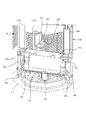
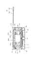
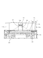
- FIG. 1 is a cross-sectional view showing a lighting device to which the air purifying device according to the embodiment of the present invention is applied.
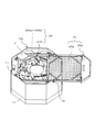
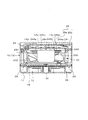
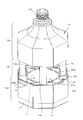
- FIG. 2 is a partially cutaway perspective sectional view showing the internal structure of the lighting device.
- FIG. 3 is a perspective view showing the structure of an axial fan.
- FIG. 4A is a perspective view showing the structure of the light source unit that irradiates the activation light.
- FIG. 4B is a perspective view showing the illumination range of each of the plurality of LEDs constituting the light source unit.
- FIG. 5 is a perspective view showing a light source unit provided in the lower housing.
- FIG. 6 is a perspective view showing the photocatalyst unit.
- FIG. 1 is a cross-sectional view showing a lighting device to which the air purifying device according to the embodiment of the present invention is applied.
- FIG. 2 is a partially cutaway perspective sectional view showing the internal structure of the lighting device.
- FIG. 3 is a perspective view showing the structure of
- FIG. 7 is a cross-sectional view showing a state immediately before mounting the photocatalyst unit on the housing (lower housing).
- FIG. 8 is a cross-sectional view showing a state immediately after starting mounting of the photocatalyst unit on the housing (lower housing).
- FIG. 9 is a perspective view showing a state immediately after starting mounting of the photocatalyst unit on the housing (lower housing).
- FIG. 10 is a cross-sectional view showing an irradiation state of the photocatalyst unit of the activated light from the light source unit in the housing (lower housing).
- FIG. 11 is a perspective view showing an irradiation state of the photocatalyst unit of the activated light from the light source unit in the housing.
- FIG. 12 shows the irradiation state of the activation light from the back UV-LED (back light source) in the housing (lower housing, middle housing) together with the irradiation state of the activation light from the light source unit. It is sectional drawing which shows.
- FIG. 13 is a perspective view showing an irradiation state of the photocatalyst unit of the activated light from the back UV-LED (back light source) in the housing.
- FIG. 14 is a perspective view showing another arrangement example of the light source unit in the housing (lower housing).
- FIG. 1 is a cross-sectional view showing a lighting device
- FIG. 2 is a partially cutaway perspective cross-sectional view showing the internal structure of the lighting device.
- the housing 10 of the lighting device 100 has a structure in which the upper housing 10a, the middle housing 10b, and the lower housing 10c are vertically connected.
- a base 20 that can be attached to a socket connected to indoor wiring is provided at an end portion of the upper housing 10a that should face upward.
- Each of the lower housing 10c and the middle housing 10b connected to each other has an octagonal square tube shape, and the upper housing 10a has an octagonal square tube shape portion connected to the middle housing 10b toward the base 20.
- the diameter is gradually reduced (see FIGS. 11 and 13 described later together with FIG. 2).
- An intake port 12 is formed at an end portion of the lower housing 10c (housing 10) that should face downward. Further, the side peripheral surface of the inner housing 10b is covered with a panel in which many slits are formed, and many slits of the panel function as an outlet 13.
- the lower housing 10c is provided with an annular lighting cover 11 so as to surround the intake port 12.
- a proximity sensor 30 that outputs a detection signal according to the degree of approach of an object (person) is provided so as to be located at the center of the intake port 12.
- a circuit board 28 is provided at the end of the lower housing 10c where the intake port 12 is formed.
- the circuit board 28 has an annular portion covered by the annular lighting cover 11 and a transverse portion that traverses the inside of the annular portion.
- a plurality of LEDs (light emitting diodes) 29 distributed and arranged as a light source (illumination unit) for illumination are mounted on the annular portion of the circuit board 28.
- a proximity sensor 30 is mounted on the cross-sectional portion of the circuit board 28.
- a pre-filter 18 is provided so as to cover the intake port 12.
- the pre-filter 18 is formed of a relatively coarse flat mesh body that does not significantly obstruct the flow of air sucked from the intake port 12.
- the pre-filter 18 prevents dust, insects, and the like from entering the lower housing 10c (housing 10).
- the lower housing 10c is provided with an axial flow fan 23 so as to face the outlet 12 (pre-filter 18).
- the axial flow fan 23 is configured as shown in FIG.
- the axial fan 23 is arranged between the motor 230, the outer frame 231 surrounding the motor 230, the outer frame 231 and the motor 230, the fan blade 232 rotated by the motor 230, and the motor 230 as the outer frame 231. It has four (plural) connecting frames 233a, 233b, 233c, and 233d to be connected to the above.
- the rotation of the fan blade 232 rotated by the motor 230 draws air into the lower housing 10c (housing 10) from the intake port 12.
- a light source unit 24 and a photocatalyst unit 25 are further provided in the lower housing 10c.
- the light source unit 24 is arranged on the downstream side of the axial flow fan 23 in the direction of the air flow (see the thick dashed arrow in FIG. 1) so as to face the axial flow fan 23, and is a photocatalyst toward the downstream direction of the air flow. Irradiate the activation light of (photocatalyst unit 25). As shown in FIG.
- the light source unit 24 has 12 (3 or more) UV-LEDs (ultraviolet light emitting diodes) 244a to 244d, 245a, each of which irradiates activation light having a predetermined wavelength (for example, 365 nm) in the ultraviolet region. It has ⁇ 245d, 246a ⁇ 246d. These UV-LEDs 244a to 244d, 245a to 245d, and 246a to 246d are mounted on the circuit board 240 so as to be distributed and arranged on one plane SF.
- UV-LEDs ultraviolet light emitting diodes
- the circuit board 240 has an annular outer peripheral ring portion 241 (outer peripheral portion), an annular central ring portion 242 (central portion) arranged inside the outer peripheral ring portion 241, and a central ring portion 242 and an outer peripheral ring portion 241. It has four (plural) connecting arms 243a, 243b, 243c, and 243d that connect with.
- Four UV-LEDs 244a, 244b, 244c, 244d are mounted on the outer ring portion 241 and four UV-LEDs 245a, 245b, 245c, 245d are mounted on the central ring portion 242.
- UV-LED246a is attached to the connecting arm portion 243a
- UV-LED246b is attached to the connecting arm portion 243b
- UV-LED246c is attached to the connecting arm portion 243c
- UV-LED246d is attached to the connecting arm portion 243d.
- activation light (ultraviolet rays) from each of the 12 UV-LEDs 244a to 244d, 245a to 245d, and 246a to 246d distributed and arranged on the plane SF (circuit board 240) as described above.
- the irradiation ranges L4a to L4d, L5a to L5d, and L6a to L6d allow the activation light (ultraviolet rays) to be irradiated to a wider surface facing the light source unit 24.
- the light source unit 24 having the above-mentioned structure is arranged in the lower housing 10c so as to face the axial flow fan 23.
- the outer peripheral ring portion 241 of the circuit board 240 faces the outer frame 231 of the axial flow fan 23
- the central ring portion 242 of the circuit board 240 faces the motor 230 of the axial flow fan 23.
- the connecting arm portion 243a of the circuit board 240 is attached to the connecting arm portion 233a of the axial flow fan 23
- the connecting arm portion 243b of the circuit board 240 is attached to the connecting arm portion 233b of the axial flow fan 23
- the connecting arm portion 243c of the circuit board 240 is the axis.
- the connecting arm portion 243d of the circuit board 240 faces the connecting frame 233c of the flow fan 23, and faces the connecting frame 233d of the axial flow fan 23, respectively.
- the light source unit 24 circuit board 240, UV-LEDs 244a to 246d
- the outer ring portion 241 and the central ring portion 242 and the four connecting arm portions 243a of the circuit board 240 are arranged.
- ⁇ 243d is hidden by the motor 230 of the axial flow fan 23, the outer frame 231 and the four connecting frames 233a to 233d with respect to the air flow generated by the axial flow fan 23.
- the photocatalyst unit 25 arranged on the downstream side in the direction of the air flow facing the light source unit 24 (circuit board 240, UV-LEDs 244a to 246d) is configured as shown in FIG.
- the photocatalyst unit 25 has a structure in which, for example, a photocatalyst body 25a in which a photocatalyst (for example, titanium dioxide) is supported on a flat metal body is supported in a plane by a support frame 25b.
- the metal flat network used for the photocatalyst body 25a is thin, for example, has a predetermined thickness of 1 mm or less, and has a finer mesh than the pre-filter 18.
- a slit extending in the lateral direction (parallel to the surface of the circuit board 240 of the light source unit 24) as an insertion port of the photocatalyst unit 25 is provided in the portion of the side surface of the lower housing 10c near the middle housing 10b.
- the holes 16 are formed.
- the flat plate-shaped photocatalyst unit 25 is inserted into the lower housing 10c (housing 10) through the slit hole 16 as shown in FIGS. 7, 8 and 9, and the light source unit 24 (as shown in FIG. 10). It is set so as to face the circuit board 240, UV-LEDs 244a to 246d).
- the photocatalyst unit 25 can be taken out from the lower housing 10c (housing 10) through the slit hole 16. With the photocatalyst unit 25 set in the lower housing 10c (housing 10) as shown in FIG. 10, activation light is emitted from each UV-LEDs 244a to 246d of the light source unit 24 into a flat net-like photocatalyst of the photocatalyst unit 25.
- the body 25a is irradiated.
- the irradiation range L4a to L6d (see FIG. 4B) of the activation light (ultraviolet rays) from the 12 UV-LEDs 244a to 246d are, for example, in FIG.
- the irradiation range L4a of the UV-LED244a and the irradiation range L5a of the UV-LED245a are covered substantially evenly.
- a rectangular opening 17 for forming an air flow to the middle housing 10b is provided on the upper surface of the lower housing 10c (the end surface opposite to the intake port 12). It is formed.
- the middle housing 10b has four columns 14a for securing a space as the middle housing 10b between the peripheral portion of the opening 17 and the upper housing 10a. 14b, 14c, 14d (see FIGS. 1 and 2 for the support column 14a) are provided. Then, by covering the circumferences of these four columns 14a, 14b, 14c, and 14d with panels having many slits as described above, the middle housing 10b having the outlet 13 formed on the side peripheral surface is configured. (See FIGS. 1 and 2).
- the middle housing 10b is provided with a circuit board 15 having both ends fixed to the columns 14a and 14c, as shown in FIG. 1 as a cross section and in FIG. 2 as a partially cutaway perspective section. ..
- the circuit board 15 has a back UV-LED 26 (a back UV-LED 26) that irradiates the photocatalyst body 25a (photocatalyst unit 25) with activation light from the opposite side of the light source unit 24, that is, from the downstream side of the photocatalyst unit 25 in the direction of air flow. (Back light source) is installed.
- the irradiation range L of the activation light from the back UV-LED 26 is set so as to cover the photocatalyst body 25a more widely as shown in FIGS.
- the activation light from the back UV-LED 26 is set to a wavelength different from the wavelength of the activation light (ultraviolet rays) from each of the UV-LEDs 244a to 246d of the light source unit 24. Specifically, it is set to a wavelength shorter than the wavelength of the activation light (for example, 365 nm) from each UV-LED 244a to 246d (for example, 275 nm: deep ultraviolet region).
- a light guide plate 31 (light guide body) made of acrylic resin or the like is described above in a predetermined portion near the middle housing 10b of the lower housing 10c. It is provided so as to face the photocatalyst body 25a (photocatalyst unit 25) through the rectangular opening 17.
- One end surface 31a of the light guide plate 31 is exposed from the side surface of the lower housing 10c (housing 10).
- the light guide plate 31 receives the activation light from the light source unit 24 passing through the flat mesh photocatalyst body 25a and propagates to the end face 31a.
- the brightness of the end face 31a of the light guide plate 31 may change depending on the amount of light propagated.
- an optical sensor 27 is further attached to the circuit board 15 on which the above-mentioned back UV-LED 26 is mounted.
- the optical sensor 27 is arranged at a position where it can receive the activation light from the light source unit 24 passing through the flat mesh photocatalyst body 25a, and outputs a detection signal according to the amount of received light.
- the upper housing 10a is provided with a power supply circuit 21 that converts alternating current electricity introduced through the base 20 into predetermined direct current electricity.
- a control circuit board 22 is provided at a portion connected to the upper housing 10a of the middle housing 10b.
- the direct current electricity from the power supply circuit 21 is transmitted to the plurality of lighting LEDs 29 mounted on the circuit board 28, the axial flow fan 23, and the 12 UV-LEDs 244a mounted on the circuit board 240 via the control circuit board 22. It is supplied to ⁇ 246d (light source unit 24) and the back UV-LED 26 mounted on the circuit board 15.
- This control circuit is a portion that controls lighting of a plurality of LEDs 29 for lighting based on a detection signal from the proximity sensor 30, and a lighting mode of the plurality of LEDs 29 (illuminating unit) based on a detection signal from the optical sensor 27.
- a portion (illumination control unit) for controlling (illumination light irradiation mode) is included.
- the lighting device 100 as described above is attached to the ceiling of the room (for example, a toilet) by attaching the base 20 to the socket installed on the ceiling. In this state, when the lighting switch is turned on, power is supplied to each part, and the lighting device 100 (air purifying device) is controlled by the control circuit configured on the control circuit board 22.
- the control circuit configured on the control circuit board 22.
- activation light (ultraviolet rays) is emitted from each of the UV-LEDs 244a to 246d of the light source unit 24, and activation light (deep ultraviolet rays) is emitted from the back UV-LED 26.
- the switch is on, the operating state of the axial flow fan 23 and the irradiation state of the activation light from the UV-LEDs 244a to 246d of the light source unit 24 and the back UV-LED 26 are maintained.
- the air in the room is purified as described later.
- a plurality of lighting LEDs 29 are turned on based on the detection signal from the proximity sensor 30 that detects the person, and the room is illuminated. ..
- the photocatalyst for example, titanium dioxide
- the photocatalyst body 25a Upon receiving this activation light (ultraviolet rays), the photocatalyst (for example, titanium dioxide) on the surface of the photocatalyst body 25a is activated to develop a strong oxidizing power, and organic substances in the air flowing in contact with the photocatalyst are decomposed. ..
- the air passing through the flat net-like photocatalyst body 25a while in contact with the photocatalyst is purified by deodorization, sterilization, etc., and the purified air is blown out from the outlet 13 through the inner housing 10b. Will be done.
- the indoor air is gradually purified by continuously drawing the indoor air into the housing 10, purifying the air, and blowing out the purified air. The condition of the clean air is maintained.
- the activation light deep ultraviolet light having a wavelength shorter than the wavelength (for example, 275 nm) of the activation light from the UV-LEDs 244a to 246d of the light source unit 24 described above from the back UV-LED 26.
- the air is purified due to the activation of the opposite surface of the photocatalyst body 25a, and the air is further purified by the action peculiar to the activation light having a short wavelength thereof.
- bacteria and viruses contained in the air that has passed through the flat net-like photocatalyst 25a are purified. In this way, air is blown into the room from the outlet 13 while receiving an additional cleaning action by the activation light from the back UV-LED 26, and the air in the room is further cleaned.
- the axial flow fan 23 arranged to face the intake port 12 positively moves from the intake port 12 into the housing 10 (lower housing 10c). Air is drawn into the air, and the air flow is formed so as to sequentially pass through the light source unit 24 and the photocatalyst unit 25 (photocatalyst body 25a) and be blown out from the air outlet 13. As a result, air can be efficiently drawn into the housing 10 and the photocatalyst body 25a can efficiently purify the air.
- the intake port 12 is formed at the end of the lower housing 10c that should face downward, when the lighting device 100 (air purifier) is attached to the ceiling or the like in the room, the intake port 12 that faces downward thereof. It is possible to efficiently draw in a wider range of air in the room.
- the photocatalyst body 25a of the photocatalyst unit 25 is formed in a flat mesh pattern (see FIG. 6), the area of the photocatalyst body 25a exposed to air can be increased, and the air can be efficiently purified. can. In addition, the photocatalyst body 25a can be made thinner.
- the 12 UV-LEDs 244a to 246d of the light source unit 24 are distributed and arranged on the plane SF facing the axial fan 23, the 12 UV-LEDs 244a to 246d are distributed by the air flow generated by the axial fan 23. It can be cooled efficiently. As a result, deterioration of each UV-LED 244a to 244d due to heat generation can be prevented and the life thereof can be extended. Further, the irradiation ranges LA4a to L6d of the activation light from the 12 UV-LEDs 244a to 246d dispersedly arranged on the plane SF cover the flat net-like photocatalyst 25a arranged opposite to the light source unit 24 substantially evenly. (See FIG. 11), so that the activation light can be effectively applied to the photocatalyst 25a.
- the outer ring portion 241 and the central ring portion 242 of the circuit board 240 of the light source unit 24 and the four connecting arm portions 243a to 243d are together with the 12 UV-LEDs 244a to 244d (light source unit 24) mounted on them.
- the air flow generated by the axial fan 23 is hidden by the motor 230 of the axial fan 23, the outer frame 231 and the four connecting frames 233a to 233d. Therefore, the turbulence of the generated air flow can be reduced.
- the wind pressure drop (pressure loss) caused by the circuit board 240 (light source unit 24: 12 UV-LEDs 244a to 246d) arranged to face the axial flow motor 23 is prevented, and the wind noise is reduced. Can be done.
- the amount of activated light substantially received by the photocatalyst body 25a due to the dust or the like is reduced, and the function of air purification of the photocatalyst is also reduced. As a result, the efficiency of air purification is further reduced.
- the amount of activated light emitted from the light source unit 24 and passing through the flat-net-like photocatalyst body 25a changes according to the degree of clogging of the photocatalyst body 25a, and at the same time, is incident on the light guide plate 31.
- the amount of light emitted also changes.
- the brightness of the end face 31a exposed from the housing 10 (lower housing 10c) of the light guide plate 31 changes.
- the degree of clogging of the photocatalyst body 25a increases, the brightness of the end surface 31a of the light guide plate 31 decreases.
- the user of the lighting device 100 has a degree of clogging of the flat mesh photocatalyst body 25a based on the brightness of the end face 31a (the degree of dust and the like adhering to the photocatalyst body 25a). Including) can be judged. If it is determined that the degree of clogging is large, the photocatalyst unit 25 (photocatalyst body 25a) can be used normally again by pulling out the photocatalyst unit 25 from the housing 10 (lower housing 10c) and cleaning it. Will be able to.
- the amount of activation light that is irradiated from the light source unit 24 and passes through the flat-net-like photocatalyst body 25a as described above changes depending on the degree of clogging of the photocatalyst body 25a.
- the amount of light received by the optical sensor 27 changes, and the detection signal of the optical sensor 27 changes accordingly.
- the control circuit control circuit board 22
- the detection signal from the optical sensor 27 indicates a decrease in the amount of light received. It is lit in a mode different from the mode of immediate lighting (illumination mode of illumination light).
- the brightness can be gradually increased over a certain period of time (for example, several seconds), or the light can be turned on after repeating blinking for a certain period of time.
- the user can determine the degree of clogging of the flat mesh photocatalyst body 25a (including the degree of dust and the like adhering to the photocatalyst body 25a) based on the lighting mode of the plurality of LEDs 29 for lighting. ..
- the processing of the control circuit based on the detection signal from the optical sensor 27 is not limited to the above-mentioned one.
- a separately provided alarm lamp can be turned on.
- an alarm signal can be transmitted to an external device (for example, a user's smartphone) based on the detection signal.
- the outer ring portion 241 and the central ring portion 242 of the circuit board 240 of the light source unit 24 and the four connecting arm portions 243a to 243d are attached to the twelve UV-LEDs 244a to 244d (light source). Together with the unit 24), the air flow generated by the axial fan 23 is hidden by the motor 230 of the axial fan 23, the outer frame 231 and the four connecting frames 233a to 233d.
- the circuit board 240 can also be arranged, for example, as shown in FIG.
- the outer peripheral ring portion 241 of the circuit board 240 faces the outer frame 231 of the axial flow fan 23, and the central ring portion 242 of the circuit board 240 faces the motor 230 of the axial flow fan 23.
- none of the connecting arm portions 243a to 243d of the circuit board 240 faces any of the connecting frames 233a to 233d of the axial flow fan 23. Even in this case, all 12 UV-LEDs 244a to 246d can be efficiently cooled by the air flow generated by the axial fan 23.
- the outer peripheral ring portion 241 and the central ring portion 242 of the circuit board 240, together with the UV-LEDs 244a to 244d and 245a-245d mounted therein, are of the axial flow fan 23 with respect to the air flow generated by the axial flow fan 23. It will be hidden behind the motor 230 and the outer frame 231. As a result, the turbulence of the air flow generated by the axial flow fan 23 can be reduced to some extent.
- UV-LEDs 244a to 246 In the case of the arrangement as shown in FIG. 14, of the 12 UV-LEDs 244a to 246, eight UV-LEDs 244a to 244d and 245a to 245d, which are two-thirds of the twelve UV-LEDs 244a to 246, are motors of the axial fan 23. It was arranged corresponding to 230 and the outer frame 231. From the viewpoint of reducing the turbulence of the air flow generated by the axial flow motor fan 23, more than half (UV-LEDs) of the plurality (3 or more) light emitting elements (UV-LEDs) constituting the light source unit 24 (in the above example). In this case, it is preferable that six or more light emitting elements (UV-LEDs) are arranged so as to face any of the motor 230 of the axial flow fan 23, the outer frame 231 and the plurality of connecting frames 233a to 233d.
- UV-LEDs six or more light emitting elements
- the photocatalyst body 25a has a structure in which a photocatalyst (for example, titanium dioxide) is supported on a flat net body, but the structure that allows air to pass through is not limited to using the flat net body.
- the photocatalyst body 25a can be formed by supporting a photocatalyst on a punching metal, an expanded metal, or another plate having a porous structure.
- the photocatalyst body 25a is not particularly limited as long as it has a structure exposed to air sucked from the intake port 12 by the axial fan 23.
- the embodiment of the light source unit 24 having three or more UV-LEDs distributed and arranged on the plane SF facing the axial flow fan 23 is a preferred embodiment, and is not limited to this in the present invention.
- the air purifying device according to the above-described embodiment has been applied to the lighting device 100, but is not limited thereto. It may be an air purifier alone that does not have a lighting unit (plurality of LEDs 29), or it may be applied to other devices.
- the configuration of the housing 10 is not limited to that described above (see FIG. 1).
- the vertical ratios of the three parts of the housing 10 may be different from those described above (see FIG. 1).
- the housing 10 may be composed of two or four or more parts, or may be a single one.
Landscapes
- Health & Medical Sciences (AREA)
- Epidemiology (AREA)
- Life Sciences & Earth Sciences (AREA)
- Animal Behavior & Ethology (AREA)
- General Health & Medical Sciences (AREA)
- Public Health (AREA)
- Veterinary Medicine (AREA)
- Disinfection, Sterilisation Or Deodorisation Of Air (AREA)
- Arrangement Of Elements, Cooling, Sealing, Or The Like Of Lighting Devices (AREA)
- Duct Arrangements (AREA)
Priority Applications (3)
| Application Number | Priority Date | Filing Date | Title |
|---|---|---|---|
| JP2022527436A JP7229619B2 (ja) | 2020-05-29 | 2020-05-29 | 空気清浄装置 |
| PCT/JP2020/021323 WO2021240774A1 (ja) | 2020-05-29 | 2020-05-29 | 空気清浄装置 |
| TW110115094A TW202206744A (zh) | 2020-05-29 | 2021-04-27 | 空氣清淨裝置 |
Applications Claiming Priority (1)
| Application Number | Priority Date | Filing Date | Title |
|---|---|---|---|
| PCT/JP2020/021323 WO2021240774A1 (ja) | 2020-05-29 | 2020-05-29 | 空気清浄装置 |
Publications (1)
| Publication Number | Publication Date |
|---|---|
| WO2021240774A1 true WO2021240774A1 (ja) | 2021-12-02 |
Family
ID=78723291
Family Applications (1)
| Application Number | Title | Priority Date | Filing Date |
|---|---|---|---|
| PCT/JP2020/021323 Ceased WO2021240774A1 (ja) | 2020-05-29 | 2020-05-29 | 空気清浄装置 |
Country Status (3)
| Country | Link |
|---|---|
| JP (1) | JP7229619B2 (https=) |
| TW (1) | TW202206744A (https=) |
| WO (1) | WO2021240774A1 (https=) |
Citations (9)
| Publication number | Priority date | Publication date | Assignee | Title |
|---|---|---|---|---|
| JPH01189322A (ja) * | 1988-01-22 | 1989-07-28 | Hitachi Ltd | 脱臭装置 |
| JPH11309202A (ja) * | 1998-04-28 | 1999-11-09 | Hitachi Ltd | 光触媒用光源 |
| JP2006059625A (ja) * | 2004-08-19 | 2006-03-02 | Matsushita Electric Ind Co Ltd | Led照明装置、ペンダント照明器具および街路灯 |
| JP2008078035A (ja) * | 2006-09-22 | 2008-04-03 | Stanley Electric Co Ltd | 照明装置 |
| JP2008104739A (ja) * | 2006-10-26 | 2008-05-08 | Sharp Corp | 空気浄化装置 |
| JP2009295578A (ja) * | 2008-06-02 | 2009-12-17 | Advanced Optoelectronic Technology Inc | 光触媒照明装置 |
| JP2013525991A (ja) * | 2010-04-26 | 2013-06-20 | チー ゼッケ,ホン | 保健および最適の照明装置 |
| JP2016048683A (ja) * | 2014-08-25 | 2016-04-07 | Apsジャパン株式会社 | 空気清浄化装置、該空気清浄化装置を用いた空気清浄化方法、及び空気清浄化システム |
| JP2017033795A (ja) * | 2015-08-03 | 2017-02-09 | シャープ株式会社 | 空気清浄機能を有する照明装置 |
Family Cites Families (1)
| Publication number | Priority date | Publication date | Assignee | Title |
|---|---|---|---|---|
| JP6317495B1 (ja) | 2017-03-08 | 2018-04-25 | 日機装株式会社 | 空気清浄装置 |
-
2020
- 2020-05-29 WO PCT/JP2020/021323 patent/WO2021240774A1/ja not_active Ceased
- 2020-05-29 JP JP2022527436A patent/JP7229619B2/ja active Active
-
2021
- 2021-04-27 TW TW110115094A patent/TW202206744A/zh unknown
Patent Citations (9)
| Publication number | Priority date | Publication date | Assignee | Title |
|---|---|---|---|---|
| JPH01189322A (ja) * | 1988-01-22 | 1989-07-28 | Hitachi Ltd | 脱臭装置 |
| JPH11309202A (ja) * | 1998-04-28 | 1999-11-09 | Hitachi Ltd | 光触媒用光源 |
| JP2006059625A (ja) * | 2004-08-19 | 2006-03-02 | Matsushita Electric Ind Co Ltd | Led照明装置、ペンダント照明器具および街路灯 |
| JP2008078035A (ja) * | 2006-09-22 | 2008-04-03 | Stanley Electric Co Ltd | 照明装置 |
| JP2008104739A (ja) * | 2006-10-26 | 2008-05-08 | Sharp Corp | 空気浄化装置 |
| JP2009295578A (ja) * | 2008-06-02 | 2009-12-17 | Advanced Optoelectronic Technology Inc | 光触媒照明装置 |
| JP2013525991A (ja) * | 2010-04-26 | 2013-06-20 | チー ゼッケ,ホン | 保健および最適の照明装置 |
| JP2016048683A (ja) * | 2014-08-25 | 2016-04-07 | Apsジャパン株式会社 | 空気清浄化装置、該空気清浄化装置を用いた空気清浄化方法、及び空気清浄化システム |
| JP2017033795A (ja) * | 2015-08-03 | 2017-02-09 | シャープ株式会社 | 空気清浄機能を有する照明装置 |
Also Published As
| Publication number | Publication date |
|---|---|
| TW202206744A (zh) | 2022-02-16 |
| JPWO2021240774A1 (https=) | 2021-12-02 |
| JP7229619B2 (ja) | 2023-02-28 |
Similar Documents
| Publication | Publication Date | Title |
|---|---|---|
| JP6595838B2 (ja) | 空気清浄機能を有する照明装置 | |
| CN211551554U (zh) | 多功能空气净化保健杀毒灯 | |
| CN214840706U (zh) | 具有消杀功能的无叶风扇筒灯 | |
| EP1802355B1 (en) | Air conditioning system | |
| KR20230114761A (ko) | 자외선 공기살균기 | |
| KR200279730Y1 (ko) | 살균 및 청정 기능을 갖는 복합조명기 | |
| KR20080073472A (ko) | 천정 매입형 공기 살균 정화기 | |
| KR20120000178U (ko) | 공기정화 장치를 구비한 조명기구 | |
| JP7229619B2 (ja) | 空気清浄装置 | |
| KR20180125833A (ko) | 공기 정화용 조명 장치 및 이를 포함하는 제어 시스템 | |
| KR20050066353A (ko) | 탈취필터를 갖춘 공기청정기 | |
| KR20140136779A (ko) | 조명과 음향이 발생되는 탈취장치 | |
| KR102689401B1 (ko) | 전등형 공기 정화 살균기 | |
| KR20040058763A (ko) | 벽걸이 액자형 공기청정기 | |
| EP4035696B1 (en) | Sterilizer and sterilizing method | |
| KR20230171097A (ko) | 클린룸용 공기청정기 | |
| KR100564907B1 (ko) | 공기소독 겸용 조명등기구 | |
| CN220453616U (zh) | 具有纳米水离子净化功能的灯具 | |
| KR20220018694A (ko) | 조명등장치 | |
| KR20210135411A (ko) | 세라믹 필터를 활용한 공기 청정기 | |
| KR101980073B1 (ko) | 공기 정화 기능을 갖는 조명등 | |
| KR102872369B1 (ko) | 실내조명용 엘이디 모듈 및 이를 이용한 실내조명등 및 광촉매 공기 청정 장치 | |
| KR100573391B1 (ko) | 공기소독기 | |
| KR102770468B1 (ko) | 공기청정 기능이 부설된 전등 | |
| KR20250146487A (ko) | 산소공급이 가능한 전열교환기용 디퓨저의 기능을 가진 조명장치 |
Legal Events
| Date | Code | Title | Description |
|---|---|---|---|
| 121 | Ep: the epo has been informed by wipo that ep was designated in this application |
Ref document number: 20937746 Country of ref document: EP Kind code of ref document: A1 |
|
| ENP | Entry into the national phase |
Ref document number: 2022527436 Country of ref document: JP Kind code of ref document: A |
|
| NENP | Non-entry into the national phase |
Ref country code: DE |
|
| 122 | Ep: pct application non-entry in european phase |
Ref document number: 20937746 Country of ref document: EP Kind code of ref document: A1 |