WO2021235099A1 - 電力変換装置 - Google Patents
電力変換装置 Download PDFInfo
- Publication number
- WO2021235099A1 WO2021235099A1 PCT/JP2021/013336 JP2021013336W WO2021235099A1 WO 2021235099 A1 WO2021235099 A1 WO 2021235099A1 JP 2021013336 W JP2021013336 W JP 2021013336W WO 2021235099 A1 WO2021235099 A1 WO 2021235099A1
- Authority
- WO
- WIPO (PCT)
- Prior art keywords
- current sensor
- power conversion
- sensor unit
- fluid
- case
- Prior art date
- Legal status (The legal status is an assumption and is not a legal conclusion. Google has not performed a legal analysis and makes no representation as to the accuracy of the status listed.)
- Ceased
Links
Images



Classifications
-
- H—ELECTRICITY
- H02—GENERATION; CONVERSION OR DISTRIBUTION OF ELECTRIC POWER
- H02M—APPARATUS FOR CONVERSION BETWEEN AC AND AC, BETWEEN AC AND DC, OR BETWEEN DC AND DC, AND FOR USE WITH MAINS OR SIMILAR POWER SUPPLY SYSTEMS; CONVERSION OF DC OR AC INPUT POWER INTO SURGE OUTPUT POWER; CONTROL OR REGULATION THEREOF
- H02M7/00—Conversion of AC power input into DC power output; Conversion of DC power input into AC power output
- H02M7/42—Conversion of DC power input into AC power output without possibility of reversal
- H02M7/44—Conversion of DC power input into AC power output without possibility of reversal by static converters
- H02M7/48—Conversion of DC power input into AC power output without possibility of reversal by static converters using discharge tubes with control electrode or semiconductor devices with control electrode
Definitions
- the disclosure in this specification relates to a power conversion device.
- Patent Document 1 describes a power conversion device in which a current sensor is arranged next to a laminated body in which a semiconductor module and a cooling tube are laminated, and the current sensor is cooled by the cooling tube.
- Patent Document 1 has room for improvement in terms of cooling capacity for cooling a current sensor having low heat resistance.
- One of the purposes disclosed in this specification is to provide a power conversion device for improving the cooling performance of the current sensor unit.
- One of the disclosed power conversion devices is a power conversion unit that converts the power input from the power source and supplies the current to the electric load, and a cooler that cools the power conversion unit by the cooling fluid flowing inside.
- a current sensor unit that measures the current in the current path connecting the power supply and the electric load, and a case that houses the power conversion unit, the cooler, and the current sensor unit are provided.
- the cooler includes a fluid inflow part in which the cooling fluid flows in from the outside and a fluid outflow part in which the cooling fluid flows out to the outside.
- the fluid inflow part and the fluid outflow part extend from the same wall in the case toward the power conversion part.
- the current sensor unit is provided closer to the same wall than the power conversion unit.
- this same wall can be cooled by the cooling fluid.
- the current sensor unit is closer to the same wall than the power conversion unit, it is possible to form a heat dissipation path in which the same wall absorbs heat from the current sensor unit and discharges it to the outside from the case surface.
- the cooling of the current sensor unit can be promoted, which contributes to lowering the heat resistant temperature of the circuit board and the board-mounted components such as the current sensor components. According to such a disclosure technique, it is possible to provide a power conversion device for improving the cooling performance of the current sensor unit.
- a first embodiment that discloses an example of a vehicle drive system and a power conversion device will be described with reference to FIGS. 1 to 3.
- the power conversion device can be applied to an in-vehicle power conversion device mounted on a vehicle such as an electric vehicle or a fuel cell vehicle. Vehicles include passenger cars, buses, construction work vehicles, agricultural machinery vehicles and the like.
- a power conversion device capable of achieving the object specified in the specification can be applied to, for example, an inverter device, a converter device, or the like.
- This converter device includes a power supply device for AC input / DC output, a power supply device for DC input / DC output, and a power supply device for AC input / AC output.
- the device applied to the inverter device as an example of the power conversion device will be described below.
- the vehicle drive system 10 is mounted on the vehicle and includes a DC power supply 300, a motor generator 310, and a power conversion device 1.
- the power conversion device 1 includes at least an inverter circuit 200, a control circuit 210, and a smoothing capacitor 3.
- the inverter circuit 200 includes a plurality of semiconductor modules 2 to form a power conversion unit.
- the power conversion unit converts the power input from the power source and supplies the current to the electric load.
- the smoothing capacitor 3 is connected in parallel to the semiconductor module 2.
- the power conversion unit converts the DC power supplied from the DC power supply 300 into AC power by turning on / off the semiconductor element 20 included in the semiconductor module 2.
- the DC power supply 300 is, for example, a plurality of secondary batteries.
- As the secondary battery a lithium ion secondary battery, a nickel hydrogen secondary battery, an organic radical battery, or the like can be adopted.
- the motor generator 310 includes a three-phase AC rotary electric machine, that is, a three-phase AC motor.
- the motor generator 310 functions as an electric motor that is a traveling drive source of the vehicle.
- the motor generator 310 functions as a generator during regeneration.
- the power conversion device 1 performs power conversion between the DC power supply 300 and the motor generator 310.
- the power conversion device 1 converts the DC voltage into a three-phase AC voltage and outputs it to the motor generator 310 according to the switching control by the control circuit 210. As a result, the vehicle runs by driving the motor generator 310 using the AC power converted from the DC power by the power conversion unit.
- the power conversion device 1 converts the AC power generated by the power generation of the motor generator 310 into DC power and outputs it to the power line on the high potential side in the circuit.
- the power conversion device 1 performs bidirectional power conversion between the DC power supply 300 and the motor generator 310.
- the motor generator 310 is connected to the axle of an electric vehicle.
- the rotational energy of the motor generator 310 is transmitted to the traveling wheels of the electric vehicle via the axle.
- the rotational energy of the traveling wheel is transmitted to the motor generator 310 via the axle.
- the motor generator 310 is powered by AC power supplied from the power conversion device 1.
- the motor generator 310 is regenerated by the rotational energy transmitted from the traveling wheels.
- the AC power generated by this regeneration is converted into DC power by the power conversion device 1.
- This DC power is supplied to the DC power supply 300.
- This DC power is also supplied to various electric loads mounted on the vehicle.
- a smoothing capacitor 3 is connected to the input side and a motor generator 310, which is an example of an electric load, is connected to the output side of the power conversion unit.
- the smoothing capacitor 3 mainly smoothes the DC voltage supplied from the DC power supply 300.
- the smoothing capacitor 3 is connected between the power line on the high potential side and the power line on the low potential side.
- the power line on the high potential side is connected to the positive electrode of the DC power supply 300.
- the power line on the low potential side is connected to the negative electrode of the DC power supply 300.
- the positive electrode of the smoothing capacitor 3 is connected to the power line on the high potential side between the DC power supply 300 and the semiconductor module 2.
- the negative electrode of the smoothing capacitor 3 is connected to the power line on the low potential side between the DC power supply 300 and the semiconductor module 2.
- a P bus bar is provided on the power line on the high potential side.
- An N bus bar is provided on the power line on the low potential side.
- the P bus bar and the N bus bar are provided on the power line on the input side with respect to the power conversion unit.
- a connection terminal 151 provided on the power line on the input side with respect to the power conversion unit is provided.
- An output terminal provided at the end of a power supply line for supplying power from the DC power supply 300 is connected to the connection terminal 151.
- the power conversion device 1 includes a three-phase leg connected in parallel between a P bus bar connected to the positive electrode of the DC power supply 300 and an N bus bar connected to the negative electrode of the DC power supply 300.
- the leg of each phase includes a plurality of semiconductor elements 20 connected in series between the P bus bar and the N bus bar.
- the inverter circuit 200 includes three upper and lower arm circuits including two arms connected in series.
- the three upper and lower arm circuits are, for example, U-phase, V-phase, and W-phase from the smoothing capacitor 3 side.
- the arm on the high potential side of each upper and lower arm circuit can be said to be an upper arm.
- the arm on the low potential side can also be said to be the lower arm.
- Each arm has an IGBT that is a switching element and a diode.
- the IGBT is an insulated gate bipolar transistor which is a kind of transistor.
- the IGBT and the diode are provided on the semiconductor substrate.
- the semiconductor chip provided with the IGBT and the diode corresponds to the semiconductor element 20.
- the collector is connected to the power line on the high potential side.
- the emitter is connected to the power line on the low potential side.
- the emitter on the upper arm side and the collector on the lower arm side are connected to each other.
- the anode of the diode is connected to the emitter of the corresponding IGBT and the cathode is connected to the collector of the corresponding IGBT.
- the control circuit 210 generates a drive command for operating the IGBT and outputs it to the drive circuit.
- the control circuit 210 generates a drive command based on, for example, a torque request input from a higher-level ECU and signals detected by various sensors.
- Various sensors include a current sensor unit 4, a rotation angle sensor, and a voltage sensor.
- the control circuit 210 outputs, for example, a PWM signal as a drive command.
- the control circuit 210 includes a microcomputer.
- the current sensor unit 4 measures the current in the current path connecting the power supply and the electric load.
- the current sensor unit 4 includes a current sensor that detects the output current of the arm, that is, the phase current flowing through the winding of each phase.
- the current sensor outputs an electric signal corresponding to the output current of the arm to the control circuit 210.
- This electrical signal is a feedback signal.
- the feedback signal is a signal corresponding to the output current.
- the rotation angle sensor detects the rotation angle of the rotor of the motor generator 310 and outputs it to the control circuit 210.
- the voltage sensor detects the voltage across the smoothing capacitor 3 and outputs it to the control circuit 210.
- the drive circuit is a driver that supplies a drive voltage to the gate of the IGBT of the corresponding arm based on the drive command of the control circuit 210.
- the drive circuit drives the corresponding IGBT, that is, on drive and off drive by applying a drive voltage.
- the power conversion device 1 of this embodiment includes one drive circuit for one arm.
- the power conversion device 1 includes an input side bus bar and an output side bus bar. Since such a bus bar forms one of the electric power paths and generates heat, it dissipates heat to surrounding parts.
- the input side bus bar is a conductive member to which electric power is supplied from the DC power supply 300.
- the input side bus bars are, for example, P bus bars and N bus bars.
- the output-side bus bar includes, for example, a bus bar 44 provided in a power path through which the output current of the arm flows to the motor generator 310.
- the current sensor detects the output current flowing through the output side bus bar.
- the output-side bus bar is provided in the power path connecting the connection portion between the upper arm and the lower arm in the U phase and the winding of the motor generator 310.
- the output-side bus bar is provided in a power path connecting the connection portion between the upper arm and the lower arm in the V phase and the winding of the motor generator 310.
- the output-side bus bar is provided in the power path connecting the connection portion between the upper arm and the lower arm in the W phase and the winding of the motor generator 310.
- the output side bus bar includes a U-phase bus bar, a V-phase bus bar, and a W-phase bus bar.
- the U-phase bus bar, V-phase bus bar, and W-phase bus bar are provided on the power line on the output side with respect to the power conversion unit.
- a connection terminal 141 provided on the power line on the output side with respect to the power conversion unit is provided.
- An input terminal provided at the end of a power supply line that supplies power to the windings of each phase of the motor generator 310 is connected to the connection terminal 141.
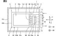
- the power conversion device 1 includes a case 11 for accommodating a plurality of electric components.
- the case 11 forms one container.
- the case 11 houses a power module unit 5, a current sensor unit 4, a capacitor unit, and the like.
- the capacitor unit contains at least a smoothing capacitor 3.
- the capacitor unit contains a resin-sealed smoothing capacitor 3 with the terminals connected to other electrical components exposed.
- the smoothing capacitor 3 has a built-in resin-sealed capacitor element.
- the resin to be sealed is made of a thermosetting resin such as an epoxy resin.
- the sealing resin portion is filled in the gap between the capacitor element and the terminal and the accommodating portion of the smoothing capacitor 3. A part of the terminal and the like of the smoothing capacitor 3 protrudes from the sealing resin portion.
- the capacitor unit is fixed to, for example, the bottom wall 11a of the case 11 by a fixing tool such as a bolt, a screw, or a rivet, or a connecting means such as a welding connection or a brazing connection.
- the case 11 is a housing formed by combining a plurality of case members.
- the case 11 includes, for example, at least a first case member and a second case member.
- the second case member is a member attached to the first case member so as to cover the internal space of the lower case, which is the first case member.
- FIG. 3 shows a state in which the member covering the internal space is removed in the case 11 for explaining the configuration of the power conversion device 1.
- the case 11 is made of a metal material.
- the case 11 includes, for example, a molded body made of die-cast aluminum.
- the X direction and the Y direction in the drawing are the horizontal direction and the vertical direction of the power conversion device 1.
- the Z direction in the drawing is the height direction of the power conversion device 1.
- the case 11 may be configured to include a resin material.
- the case 11 includes, for example, a bottom wall 11a and a plurality of side walls erected from the peripheral edge of the bottom wall 11a.
- the plurality of side walls include a first side wall 11b and a second side wall 11c facing in the X direction, and a third side wall 11d and a fourth side wall 11e facing in the Y direction.
- the first side wall 11b is adjacent to the third side wall 11d and the fourth side wall 11e.
- the second side wall 11c is adjacent to the third side wall 11d and the fourth side wall 11e.
- the semiconductor module 2 includes a main body portion in which the semiconductor element 20 is built, and a power terminal and a signal terminal protruding from the main body portion.
- the semiconductor module 2 is also called a power module.
- the power terminal and the signal terminal project in opposite directions in the semiconductor module 2.
- the power terminal includes an input terminal to which a DC voltage is applied and an output terminal connected to an output side bus bar on the motor generator 310 side.
- the input terminal is connected to the terminal of the smoothing capacitor 3 and is electrically connected to the output unit of the DC power supply 300 via the input side bus bar.
- the signal terminal is connected to a control circuit mounted on the control board.
- the control circuit constitutes a circuit in which electronic components such as arithmetic elements that control the operation of the semiconductor element 20 are mounted.
- the power conversion device 1 includes a cooler 6 that cools the semiconductor module 2 by the endothermic action of the cooling fluid flowing inside.
- the power module unit 5 includes a plurality of semiconductor modules 2 integrally formed and a cooler 6.
- the cooler 6 is fixed to the case 11 by, for example, a fixture such as a bolt, a screw, or a rivet, or a connecting means such as a welded bond or a brazed bond.
- the power module unit 5 includes a plurality of semiconductor modules 2 and a cooler 6 for cooling the semiconductor modules 2.
- the cooler 6 and the semiconductor module 2 are stacked in the height direction and installed integrally.
- the cooler 6 has an upper wall surface that contacts one side of the semiconductor module 2.
- the cooler 6 has a built-in cooling passage through which a cooling fluid flows between the upper wall surface and the lower wall surface.
- the cooler 6 includes an inflow pipe 61, a cooling passage forming portion 63, an outflow pipe 65, and the like.
- Each part of the cooler 6 forming a passage is made of a material having good thermal conductivity, and is made of aluminum as an example.
- the cooling passage forming portion 63 has a rectangular parallelepiped shape having a first side wall 63a and a second side wall 63b at opposite positions, and a third side wall 63c and a fourth side wall 63d at opposite positions.
- the first side wall 63a and the second side wall 63b face each other in the X direction.
- the first side wall 63a faces the cooler 6 side and the first side wall 11b side of the case 11.
- the second side wall 63b faces the second side wall 11c side of the case 11.
- the third side wall 63c and the fourth side wall 63d face each other in the Y direction.
- the third side wall 63c faces the third side wall 11d side of the case 11.
- the fourth side wall 63d faces the fourth side wall 11e side of the case 11.
- the inflow pipe 61 is a fluid inflow portion in which the cooling fluid from the outside flows into the cooler 6.
- the downstream portion of the inflow pipe 61 is connected to the upstream side connecting portion 62 in the cooling passage forming portion 63.
- the upstream portion of the inflow pipe 61 is connected to the external introduction pipe 71.
- the inflow pipe 61 extends from the first side wall 11b in the case 11 toward the power conversion unit to the upstream connecting portion 62.
- the inflow pipe 61 forms an inflow passage extending from the first side wall 11b of the case 11 to the first side wall 63a of the cooling passage forming portion 63.
- the external introduction pipe 71 is an external pipe that forms a passage communicating with the inflow pipe 61, and extends from the first side wall 11b to the outside of the case 11.
- the external introduction pipe 71 is connected to the power conversion device 1 in order to form a passage for introducing the cooling fluid into the cooler 6.
- a seal portion is provided between the outer surface of the external introduction pipe 71 and the inner surface of the through hole formed in the first side wall 11b of the case 11. This seal portion is in close contact with the external introduction pipe 71 and the case 11 to prevent water from entering the case 11 from the outside.
- the outflow pipe 65 is a fluid outflow portion in which the cooling fluid flows out to the outside in the cooler 6.
- the upstream portion of the outflow pipe 65 is connected to the downstream connecting portion 64 in the cooling passage forming portion 63.
- the downstream portion of the outflow pipe 65 is connected to the external discharge pipe 72.
- the outflow pipe 65 extends from the first side wall 11b in the case 11 toward the power conversion unit to the downstream connecting portion 64.
- the outflow pipe 65 forms an outflow passage extending from the first side wall 11b of the case 11 to the first side wall 63a of the cooling passage forming portion 63.
- the external discharge pipe 72 is an external pipe that forms a passage communicating with the outflow pipe 65, and extends from the first side wall 11b to the outside of the case 11.
- the external discharge pipe 72 is connected to the power conversion device 1 in order to form a passage for discharging the cooling fluid from the cooler 6.
- a seal portion is provided between the outer surface of the external discharge pipe 72 and the inner surface of the through hole formed in the first side wall 11b of the case 11. This seal portion is in close contact with the external discharge pipe 72 and the case 11 to prevent water from entering the case 11 from the outside.
- the cooling fluid flowing through the cooling passage forming portion 63 absorbs heat from the adjacent semiconductor module 2 and cools the cooling fluid.
- the cooling passage in the cooling passage forming portion 63 communicates with the internal passage of the inflow pipe 61 on the upstream side and communicates with the internal passage of the outflow pipe 65 on the downstream side.
- the cooling fluid flowing inside the cooler 6 is preferably an antifreeze liquid having a large heat capacity such as LLC. Further, a gas such as air may be adopted as the cooling fluid.
- the external introduction pipe 71 and the external discharge pipe 72 communicate with a heat dissipation device installed outside the power conversion device 1.
- the heat radiating device is a device such as a heat exchanger that dissipates heat from the cooling fluid to the outside.
- the radiator is, for example, a radiator.
- the cooling fluid is introduced into the cooling passage forming portion 63 from the heat radiating device via the external introduction pipe 71.
- the cooling fluid flows from the inflow pipe 61 into the cooling passage, absorbs heat, and flows out into the outflow pipe 65.
- the cooling fluid flows out of the cooler 6 and returns to the heat radiating device via the inside of the external discharge pipe 72.
- the current sensor unit 4 has a built-in current sensor component 43 and a circuit board 42 on which the current sensor component 43 is mounted.
- the current sensor included in the current sensor unit 4 includes a resistance detection type sensor or a magnetic field detection type sensor.
- Current sensors that perform current detection using resistance detection include shunt resistors and high speed amplifiers.
- the resistance detection type current sensor component 43 includes an electronic component having a circuit that converts a voltage drop due to a shunt resistance into a current and detects a current value.
- the current sensor that detects the current using the magnetic field detection includes the Hall IC that is the current sensor component 43.
- the Hall IC detects a current value by converting a magnetic field generated around a current into a voltage by the Hall effect and measuring the voltage.
- the magnetic field detection type current sensor component 43 includes an electronic component having a Hall element and an amplifier circuit, and is mounted on a surface of the circuit board 42 located on the power conversion unit side. Further, the magnetic field detection type current sensor component 43 may be a current sensor that non-contactly detects a magnetic field by an MI (Magneto Impedance) element.
- MI Magnetic Impedance
- the current sensor unit 4 is provided adjacent to the cooler 6 on the side of the cooler 6.
- the current sensor unit 4 has a portion whose height position overlaps with at least one of the cooling passage forming portion 63, the fluid inflow portion, and the fluid outflow portion.
- the current sensor unit 4 has a portion where the height position overlaps with both the fluid inflow portion and the fluid outflow portion. According to this configuration, the heat generated by the current sensor unit 4 can be efficiently absorbed from both the fluid inflow section and the fluid outflow section. As a result, the heat of the current sensor unit 4 can be dissipated from the two facing surfaces, so that the heat dissipation area of the current sensor unit 4 can be expanded.
- the current sensor unit 4 preferably has a portion where the height position overlaps with the cooling passage forming portion 63, the fluid inflow portion, and the fluid outflow portion.
- the heat generated by the current sensor unit 4 can be efficiently absorbed from the cooling passage forming portion 63, the fluid inflow portion, and the fluid outflow portion.
- the current sensor unit 4 can absorb heat from three sides, so that the heat dissipation area of the current sensor unit 4 can be expanded.
- the circuit board 42 is provided inside the current sensor unit 4 at a position closer to the first side wall 11b of the case 11 and in a posture along the first side wall 11b.
- the first side wall 11b corresponds to the same wall in the case 11.
- the circuit board 42 is provided close to the first side wall 11b on the side of the first side wall 11b.
- the circuit board 42 is provided between the fluid inflow portion and the fluid outflow portion in the cooler 6.
- the circuit board 42 has a portion that horizontally overlaps with the inflow pipe 61 or the outflow pipe 65. It is preferable that the circuit board 42 is provided so as to be entirely horizontally overlapped with both the fluid inflow portion and the fluid outflow portion.
- the current sensor unit 4 includes a sealing resin portion 41 that incorporates a circuit board 42, a bus bar 44, and the like in a state where terminals and the like connected to other electric components are exposed.
- the sealing resin portion 41 made of a thermosetting resin such as an epoxy resin is filled around the circuit board 42, the current sensor component 43, and a part of the bus bar 44 to cover these parts.
- the sealing resin portion 41 forms the outer wall surface of the current sensor unit 4.
- a part of the resin-sealed bus bar 44 and the current sensor component 43 are provided at positions where they overlap each other.
- the current sensor unit 4 has a first outer wall surface and a second outer wall surface located on the side opposite to the first outer wall surface.
- the first outer wall surface and the second outer wall surface are outer surfaces facing each other in the direction in which the inflow pipe 61 and the outflow pipe 65 extend.
- the first outer wall surface is an outer surface close to the first side wall 11b of the case 11 and the circuit board 42.
- the second outer wall surface is an outer surface that is closer to the bus bar 44 than the circuit board 42.
- the first surface which is one side surface of the circuit board 42, is a surface on which the current sensor component 43 is not mounted, and is located on the first side wall 11b side and is provided along the first side wall 11b.
- the second surface which is the other side surface of the circuit board 42, is the surface on which the current sensor component 43 is mounted, and is located on the side opposite to the first side wall 11b.
- the current sensor unit 4 is fixed to the case 11 by a fixing tool such as a bolt, a screw, a rivet, a welding connection, a brazing connection, or the like.
- the current sensor unit 4 may be fixed in a state where the first outer wall surface is in contact with the first side wall 11b.
- the current sensor unit 4 may have the configuration shown below.
- the current sensor unit 4 may have a configuration in which a circuit board 42, a bus bar 44, and the like are built in the outer case.
- the outer case is a housing made of metal or resin.
- the outer case forms the outer surface of the current sensor unit 4.
- the outer case is fixed to the case 11 by a fixing tool such as a bolt, a screw or a rivet, or a connecting means such as a welded joint or a brazed joint.
- the heat in the current sensor unit 4 can be transmitted to the outer case and absorbed by the first side wall, the inflow pipe 61, the outflow pipe 65, the first side wall 63a of the cooling passage forming portion 63, the bottom wall 11a, and the like.
- the power conversion device 1 includes a power conversion unit and a cooler 6 integrally formed, and a current sensor unit 4.
- the current sensor unit 4 measures the current in the current path connecting the DC power supply 300 and the electric load.
- the power conversion device 1 includes a semiconductor module 2, a cooler 6, a current sensor unit 4, and at least a case 11 for accommodating the semiconductor module 2.
- the cooler 6 includes a fluid inflow section into which the cooling fluid from the outside flows in, and a fluid outflow section in which the cooling fluid flows out to the outside.
- the fluid inflow section and the fluid outflow section extend from the same wall in the case 11 toward the power conversion section.
- the current sensor unit 4 is provided closer to the same wall than the power conversion unit.
- the same wall can be cooled more positively than the other side walls by the cooling fluid. Further, the current sensor unit 4 is closer to this same wall than the power conversion unit.
- the power conversion device 1 can construct a heat dissipation path in which the same wall absorbs heat from the current sensor unit 4 and dissipates heat from the case surface to the outside. The power conversion device 1 can improve the cooling performance of the current sensor unit 4.
- the current sensor unit 4 incorporates a circuit board 42 and a board-mounted component including the current sensor component 43.
- the circuit board 42 and the board-mounted components can be cooled by the same wall of the case 11. Due to this cooling promotion effect, the heat resistant temperature of the board-mounted component can be lowered, the reliability of the mounted component can be improved, and the cost of the mounted component can be reduced.
- the circuit board 42 is provided inside the current sensor unit 4 at a position near the same wall of the case 11. According to this configuration, the circuit board 42 and the board-mounted components can be positively cooled by the same wall of the case 11. Due to this cooling promotion effect, the heat resistant temperature of the circuit board 42 and the like can be lowered, the reliability of the mounted components can be improved, and the cost of the mounted components can be reduced. Therefore, the reliability of the power conversion device 1 that can handle a large current can be further improved.
- the current sensor unit 4 is provided between the fluid inflow section and the fluid outflow section. According to this configuration, heat can be dissipated from two opposing surfaces in the current sensor unit 4, the heat dissipation area can be expanded, and the cooling performance of the current sensor unit 4 can be improved.
- the current sensor unit 4 is provided at a position overlapping both the fluid inflow section and the fluid outflow section. According to this configuration, in the current sensor unit 4, the amount of heat radiated from the portion overlapping both the fluid inflow portion and the fluid outflow portion can be increased, and the cooling performance of the current sensor unit 4 can be improved.
- the circuit board 42 includes a first surface on which the current sensor component 43 is not mounted, and a second surface located on the opposite side of the first surface and on which the current sensor component 43 is mounted.
- the first surface faces the first side wall 11b side.
- the second surface faces the power conversion unit side opposite to the first side wall 11b.
- the power conversion device 101 of the second embodiment will be described with reference to FIGS. 4 and 5.
- the power conversion device 101 of the second embodiment is different from the first embodiment in that the current sensor unit 104 is fixed to the bottom wall 11a of the case 11.
- the configurations, actions, and effects that are not particularly described in the second embodiment are the same as those in the first embodiment, and the differences from the first embodiment will be described below.
- the current sensor unit 104 includes a fixed portion 142 fixed to the bottom wall 11a of the case 11.
- a single or a plurality of fixed portions 142 are provided in the sealing resin portion 41 of the current sensor unit 104 or the outer case.
- the fixed portion 142 is provided on the outer surface of the current sensor unit 104 on the inflow pipe 61 side and the outer surface on the outflow pipe 65 side, respectively.
- the outer case of the current sensor unit 104 is made of a metal or resin material.
- the fixed portion 142 is formed of a metal or resin material.
- the fixed portion 142 is fixed to the bottom wall 11a by a fixing tool 143 such as a bolt, a screw, or a rivet, or a connecting means such as a welded joint or a brazed joint.
- the current sensor unit 104 is fixed in a state where its bottom surface is in contact with the case 11.
- the current sensor unit 104 includes a fixed portion 142 fixed to the case 11. According to this configuration, it is possible to construct a heat dissipation path for drawing heat from the current sensor unit 104 to the case 11 via the fixed portion 142, and the cooling performance can be improved.
- the fixed portion 142 and the case 11 are made of metal. According to this configuration, it is possible to promote heat transfer in which the heat of the current sensor unit 104 is transferred to the case 11 via the fixed portion 142 having a high thermal conductivity.
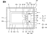
- the power conversion device 201 of the third embodiment will be described with reference to FIG.
- the power conversion device 201 differs from the second embodiment in the fixed position of the current sensor unit 204.
- the configurations, actions, and effects that are not particularly described in the third embodiment are the same as those in the above-described embodiment, and the differences from the above-described embodiment will be described below.
- the current sensor unit 204 is provided at a position closer to the fluid inflow portion located on the upstream side of the cooler 6 than the fluid outflow portion located on the downstream side of the cooler 6.
- the current sensor unit 204 is provided so that the outer surface 41a facing the inflow pipe 61 side is closer to the inflow pipe 61 than the outer surface 41b facing the outflow pipe 65 side.
- the current sensor unit 204 may be endothermic from both the fluid inflow and outflow sections.
- the fluid flowing through the inflow pipe 61, which is the fluid inflow portion has a lower temperature than the fluid flowing through the outflow pipe 65, which is the fluid outflow portion. As a result, the heat generated by the current sensor unit 4 can be efficiently absorbed by the fluid flowing through the fluid inflow portion.
- the fixed portion 142 is fixed to the bottom wall 11a at a position closer to the fluid inflow portion than the fluid outflow portion.
- the current sensor unit 4 has a portion where the height position overlaps with the fluid inflow portion. According to this configuration, since the current sensor unit 4 faces the fluid inflow portion, the effect of absorbing heat from the current sensor unit 4 by the fluid inflow portion can be further enhanced.
- the current sensor unit 204 of the third embodiment is located closer to the fluid inflow portion than the fluid outflow portion. According to this configuration, the amount of heat absorbed from the current sensor unit 204 can be increased by the low-temperature fluid before the heat is absorbed from the power conversion unit. Thereby, it is possible to provide the power conversion device 201 having further improved the cooling performance of the current sensor unit 204.
- the power conversion device capable of achieving the object disclosed in the specification may be configured not to include the control circuit 210.
- a higher-level ECU or the like may be provided with the same function as the control circuit 210.
- a drive circuit is provided for each arm, but the present invention is not limited to this configuration.
- one drive circuit may be provided for one upper and lower arm.
- the power conversion device that can achieve the object disclosed in the specification may be configured to further include a converter as a power conversion circuit.
- the converter is provided between the DC power supply 300 and the smoothing capacitor 3.
- the converter can be configured with a reactor and upper and lower arm circuits.
- the power conversion device may be configured to include a filter capacitor that removes power supply noise from the DC power supply 300.
- the filter capacitor is provided between the DC power supply 300 and the converter.
- the cooler 6 included in the power conversion device capable of achieving the object disclosed in the specification is not limited to the configuration described in the above-described embodiment.
- this cooler may be configured to include an inflow pipe 61, an upstream side connecting pipe, a plurality of passage pipes alternately stacked and installed on the semiconductor module 2, a downstream side connecting pipe, an outflow pipe 65, and the like.
- the passage pipe portion is a square cylinder that is flat in the stacking direction.
- the inside of the square cylinder is a rectangular parallelepiped cooling passage.
- the cooling passage is an internal passage of the passage pipe portion.
- the cooling fluid absorbs heat generated by the semiconductor module 2 when flowing through the cooling passage.
- the passage pipe portion is in contact with the semiconductor module 2 on both end faces orthogonal to the stacking direction.
- the semiconductor module 2 is cooled at both end surfaces by passage pipe portions adjacent to each other in the stacking direction.
- the passage pipe portion is formed with an upstream side through hole portion and a downstream side through hole portion that penetrate in the stacking direction on both ends in the longitudinal direction.
- the inner peripheral edge of the upstream side through hole portion located on the upstream side is joined to the upstream side connecting pipe.
- the inner peripheral edge of the downstream side through hole portion located on the downstream side is joined to the downstream side connecting pipe.
- the upstream side connecting pipe connects the upstream side through hole portions in the passage pipe portions adjacent to each other in the stacking direction.
- the upstream side connecting pipe provides a communication passage that communicates the internal passage of the passage pipe portion adjacent to each other in the stacking direction and the internal passage of the passage pipe portion on the upstream side of the cooler.
- the downstream side connecting pipe connects the downstream side through hole portions in the passage pipe portions adjacent to each other in the stacking direction.
- the downstream connecting pipe provides a connecting passage that communicates the internal passage of the passage pipe portion adjacent to each other in the stacking direction and the internal passage of the passage pipe portion on the downstream side of the cooler.
Landscapes
- Engineering & Computer Science (AREA)
- Power Engineering (AREA)
- Inverter Devices (AREA)
Priority Applications (1)
| Application Number | Priority Date | Filing Date | Title |
|---|---|---|---|
| CN202180032831.5A CN115516751A (zh) | 2020-05-19 | 2021-03-29 | 电力转换装置 |
Applications Claiming Priority (2)
| Application Number | Priority Date | Filing Date | Title |
|---|---|---|---|
| JP2020-087532 | 2020-05-19 | ||
| JP2020087532A JP7196879B2 (ja) | 2020-05-19 | 2020-05-19 | 電力変換装置 |
Publications (1)
| Publication Number | Publication Date |
|---|---|
| WO2021235099A1 true WO2021235099A1 (ja) | 2021-11-25 |
Family
ID=78606983
Family Applications (1)
| Application Number | Title | Priority Date | Filing Date |
|---|---|---|---|
| PCT/JP2021/013336 Ceased WO2021235099A1 (ja) | 2020-05-19 | 2021-03-29 | 電力変換装置 |
Country Status (3)
| Country | Link |
|---|---|
| JP (1) | JP7196879B2 (https=) |
| CN (1) | CN115516751A (https=) |
| WO (1) | WO2021235099A1 (https=) |
Families Citing this family (1)
| Publication number | Priority date | Publication date | Assignee | Title |
|---|---|---|---|---|
| WO2024034163A1 (ja) * | 2022-08-08 | 2024-02-15 | アルプスアルパイン株式会社 | 電流センサおよび電流制御システム |
Citations (1)
| Publication number | Priority date | Publication date | Assignee | Title |
|---|---|---|---|---|
| JP2012005323A (ja) * | 2010-06-21 | 2012-01-05 | Hitachi Automotive Systems Ltd | 電力変換装置 |
Family Cites Families (3)
| Publication number | Priority date | Publication date | Assignee | Title |
|---|---|---|---|---|
| JP4403753B2 (ja) * | 2003-08-26 | 2010-01-27 | 株式会社日立製作所 | 電力変換装置 |
| JP6743782B2 (ja) * | 2017-08-11 | 2020-08-19 | 株式会社デンソー | 電力変換装置 |
| JP6825542B2 (ja) * | 2017-11-20 | 2021-02-03 | 株式会社デンソー | 電力変換装置 |
-
2020
- 2020-05-19 JP JP2020087532A patent/JP7196879B2/ja active Active
-
2021
- 2021-03-29 CN CN202180032831.5A patent/CN115516751A/zh active Pending
- 2021-03-29 WO PCT/JP2021/013336 patent/WO2021235099A1/ja not_active Ceased
Patent Citations (1)
| Publication number | Priority date | Publication date | Assignee | Title |
|---|---|---|---|---|
| JP2012005323A (ja) * | 2010-06-21 | 2012-01-05 | Hitachi Automotive Systems Ltd | 電力変換装置 |
Also Published As
| Publication number | Publication date |
|---|---|
| JP2021182821A (ja) | 2021-11-25 |
| JP7196879B2 (ja) | 2022-12-27 |
| CN115516751A (zh) | 2022-12-23 |
Similar Documents
| Publication | Publication Date | Title |
|---|---|---|
| JP4934712B2 (ja) | 電力変換装置 | |
| JP5502805B2 (ja) | パワーモジュールおよびそれを用いた電力変換装置 | |
| CN101064485B (zh) | 电路装置、电路模块和电力变换装置和车载电机系统 | |
| JP5557441B2 (ja) | 電力変換装置および電動車両 | |
| JP4305537B2 (ja) | 電力変換装置 | |
| JP5978151B2 (ja) | 電力変換装置 | |
| JP6147893B2 (ja) | 電力変換装置 | |
| JP2014113053A (ja) | 電力変換装置 | |
| JP7544288B2 (ja) | 電力変換装置 | |
| WO2022009655A1 (ja) | 電力変換装置 | |
| JP2021182820A (ja) | 電力変換装置 | |
| JP5188530B2 (ja) | パワーモジュール及びそれを用いた電力変換装置 | |
| WO2021235099A1 (ja) | 電力変換装置 | |
| US20240088013A1 (en) | Power control apparatus | |
| US20240213887A1 (en) | Power conversion device | |
| US20230328938A1 (en) | Power module | |
| JP7392583B2 (ja) | 電力変換装置 | |
| JP2019013149A (ja) | パワーモジュール及び電力変換装置 | |
| JP6430584B2 (ja) | 電力変換装置 | |
| JP7452355B2 (ja) | 電力変換装置 | |
| JP7310715B2 (ja) | 電力変換装置 | |
| JP2021164170A (ja) | 電力変換装置 | |
| JP2021182807A (ja) | 電力変換装置 |
Legal Events
| Date | Code | Title | Description |
|---|---|---|---|
| 121 | Ep: the epo has been informed by wipo that ep was designated in this application |
Ref document number: 21808407 Country of ref document: EP Kind code of ref document: A1 |
|
| NENP | Non-entry into the national phase |
Ref country code: DE |
|
| 122 | Ep: pct application non-entry in european phase |
Ref document number: 21808407 Country of ref document: EP Kind code of ref document: A1 |