WO2021234937A1 - 警報制御装置及び警報制御方法 - Google Patents
警報制御装置及び警報制御方法 Download PDFInfo
- Publication number
- WO2021234937A1 WO2021234937A1 PCT/JP2020/020254 JP2020020254W WO2021234937A1 WO 2021234937 A1 WO2021234937 A1 WO 2021234937A1 JP 2020020254 W JP2020020254 W JP 2020020254W WO 2021234937 A1 WO2021234937 A1 WO 2021234937A1
- Authority
- WO
- WIPO (PCT)
- Prior art keywords
- alarm
- terminal
- vehicle
- control device
- acquisition unit
- Prior art date
- Legal status (The legal status is an assumption and is not a legal conclusion. Google has not performed a legal analysis and makes no representation as to the accuracy of the status listed.)
- Ceased
Links
Images







Classifications
-
- B—PERFORMING OPERATIONS; TRANSPORTING
- B60—VEHICLES IN GENERAL
- B60W—CONJOINT CONTROL OF VEHICLE SUB-UNITS OF DIFFERENT TYPE OR DIFFERENT FUNCTION; CONTROL SYSTEMS SPECIALLY ADAPTED FOR HYBRID VEHICLES; ROAD VEHICLE DRIVE CONTROL SYSTEMS FOR PURPOSES NOT RELATED TO THE CONTROL OF A PARTICULAR SUB-UNIT
- B60W40/00—Estimation or calculation of non-directly measurable driving parameters for road vehicle drive control systems not related to the control of a particular sub unit, e.g. by using mathematical models
- B60W40/02—Estimation or calculation of non-directly measurable driving parameters for road vehicle drive control systems not related to the control of a particular sub unit, e.g. by using mathematical models related to ambient conditions
-
- G—PHYSICS
- G08—SIGNALLING
- G08G—TRAFFIC CONTROL SYSTEMS
- G08G1/00—Traffic control systems for road vehicles
- G08G1/16—Anti-collision systems
Definitions
- This disclosure relates to an alarm control device and an alarm control method.
- Patent Document 1 A system that issues an alarm when there is a high possibility of a vehicle colliding with a pedestrian is known.
- Patent Document 1 when it is determined that there is a possibility of collision based on the positional relationship between the vehicle and the pedestrian, an alarm is issued to the pedestrian from the mobile terminal possessed by the pedestrian to call attention.
- Technology has been proposed.
- Patent Document 1 even when it is fully recognized that a pedestrian may collide with a vehicle, an alarm is uniformly issued based on the positional relationship between the vehicle and the pedestrian. Therefore, there is a problem that the alarm may be annoying to pedestrians. On the other hand, when a pedestrian uses a mobile terminal and the pedestrian's attention to the vehicle is low, it is desirable to actively issue an alarm.
- the present disclosure has been made in view of the above-mentioned problems, and an object thereof is to provide a technique capable of appropriately controlling an alarm for contact between a vehicle and a terminal owner of a mobile terminal.
- the alarm control device is acquired by the acquisition unit and the acquisition unit that acquire the positional relationship between the vehicle and the mobile terminal and the terminal usage state that is the usage state of the mobile terminal by the terminal owner of the mobile terminal. Based on the positional relationship, a contact determination is made to determine whether the vehicle and the terminal owner are in contact with each other, and when it is determined in the contact determination that the vehicle and the terminal owner are in contact with each other, a plurality of alarm modes are set. From the inside, it is provided with a control unit that controls the alarm of the alarm device in the alarm mode associated with the terminal usage state acquired by the acquisition unit in advance.
- the alarm mode previously associated with the terminal usage state acquired by the acquisition unit is selected from the plurality of alarm modes. Controls the alarm of the alarm device. According to such a configuration, it is possible to appropriately control the alarm for the contact between the vehicle and the terminal holder of the mobile terminal.
- FIG. It is a block diagram which shows the structure of the alarm control device which concerns on Embodiment 1.
- FIG. It is a block diagram which shows the structure of the alarm control apparatus which concerns on Embodiment 2.
- FIG. It is a figure which shows an example of the plurality of alarm modes which concerns on Embodiment 2.
- FIG. It is a figure which shows the display example by the alarm control device which concerns on Embodiment 2.
- FIG. It is a figure which shows the display example by the alarm control device which concerns on Embodiment 2.
- FIG. It is a figure which shows the display example by the alarm control device which concerns on Embodiment 2.
- FIG. It is a figure which shows the display example by the alarm control device which concerns on Embodiment 2.
- FIG. It is a figure which shows the display example by the alarm control device which concerns on Embodiment 2.
- FIG. It is a figure which shows the display example by the alarm control device which concerns on Embodiment 2.
- FIG. It is a figure which shows the
- FIG. 2 It is a flowchart which shows the operation of the alarm control apparatus which concerns on Embodiment 2. It is a block diagram which shows the structure of the alarm control apparatus which concerns on the modification 2 of Embodiment 2. It is a block diagram which shows the structure of the alarm control apparatus which concerns on the modification 3 of Embodiment 2. It is a block diagram which shows the structure of the alarm control apparatus which concerns on the modification 4 of Embodiment 2. It is a block diagram which shows the structure of the alarm control device which concerns on Embodiment 3.
- FIG. It is a figure which shows an example of the plurality of alarm modes which concerns on Embodiment 3.
- FIG. It is a figure which shows the display example by the alarm control device which concerns on Embodiment 3.
- FIG. It is a flowchart which shows the operation of the alarm control apparatus which concerns on Embodiment 3.
- FIG. It is a block diagram which shows the structure of the alarm control apparatus which concerns on the modification of Embodiment 3. It is a block diagram which shows the structure of the alarm control apparatus which concerns on Embodiment 4.
- FIG. It is a flowchart which shows the operation of the vehicle apparatus which concerns on Embodiment 4.
- FIG. 1 is a block diagram showing a configuration of an alarm control device 1 according to the first embodiment.
- the alarm control device 1 of FIG. 1 is wirelessly or wiredly connected to the alarm device 51 so as to be able to control the alarm of the alarm device 51.
- the alarm device 51 issues an alarm for contact such as a collision between the vehicle and the terminal owner of the mobile terminal under the control of the alarm control device 1.
- Mobile terminals include, for example, mobile phones, smartphones, tablets and the like.
- the terminal holder may be a pedestrian or a rider such as a bicycle.
- the alarm device 51 may include a display device that issues an alarm by display, or may include a voice output device that issues an alarm sound or alarm content by voice output. .. Further, the alarm control device 1 and the alarm device 51 may be provided in the vehicle, may be provided in the mobile terminal, or may be distributed between the vehicle and the mobile terminal. In addition, in the example of FIG. 1, the alarm device 51 is not provided in the alarm control device 1, but may be provided in the alarm control device 1.
- the alarm control device 1 of FIG. 1 includes an acquisition unit 11 and a control unit 12.
- the acquisition unit 11 acquires the positional relationship between the vehicle and the mobile terminal.
- the positional relationship between the vehicle and the mobile terminal may be the absolute position (for example, longitude and latitude) of each of the vehicle and the mobile terminal, or may be the relative position of the other with respect to one of the vehicle and the mobile terminal.
- the above-mentioned functions of the acquisition unit 11 include, for example, an image recognition device that acquires the position of the other based on an image taken by one of the vehicle and the mobile terminal, and a GPS (Global Positioning System) that detects the position of the vehicle and the mobile terminal.
- a GNSS (Global Navigation Satellite System) receiving device such as a receiving device, a communication device provided on one of a vehicle and a mobile terminal and receiving a position from the other, and at least one of these interfaces are used.
- the acquisition unit 11 acquires the terminal usage state, which is the usage state of the mobile terminal by the terminal owner of the mobile terminal.
- the above-mentioned functions of the acquisition unit 11 include, for example, an image recognition device that acquires a terminal usage state based on an image of a terminal owner taken by a vehicle, a communication device that acquires a terminal usage state from a control device of a mobile terminal, and a communication device. , At least one of these interfaces is used.
- the control unit 12 makes a contact determination to determine whether or not the vehicle and the terminal holder are in contact with each other based on the positional relationship acquired by the acquisition unit 11. Further, when the control unit 12 determines in the contact determination that the vehicle and the terminal owner come into contact with each other, the alarm mode associated with the terminal usage state acquired by the acquisition unit 11 in advance from among the plurality of alarm modes Controls the alarm of the alarm device 51.
- the alarm control device 1 when the contact is determined and the contact determination determines that the vehicle and the terminal owner are in contact with each other, the acquired terminal usage state is set.
- the alarm of the alarm device 51 is controlled in the alarm mode associated in advance. According to such a configuration, even when it is determined that the vehicle and the terminal owner come into contact with each other, the terminal owner does not use the mobile terminal and the terminal owner's attention to the vehicle is compared. If the target is high, a mild alarm can be issued or the alarm can be stopped. On the other hand, if the terminal owner is using a mobile terminal and the terminal owner's attention to the vehicle is relatively low, a severe alarm can be issued. Therefore, it is possible to appropriately give an alarm for contact between the vehicle and the terminal holder of the mobile terminal. Furthermore, it can be expected that the power consumption used for the alarm will be reduced by appropriately suppressing the issuance of the alarm.
- FIG. 2 is a block diagram showing a configuration of the alarm control device 1 according to the second embodiment.
- the same or similar components as those described above will be designated by the same or similar reference numerals, and different components will be mainly described.
- the alarm control device 1 of FIG. 2 is wirelessly or wiredly connected to a HUD (Head-Up Display) 51a, a CID (Center Information Display) 51b, an audio output device 51c, and an in-vehicle camera 52.
- the alarm control device 1 is applied to an in-vehicle infotainment device and the like, and the component of FIG. 2 is assumed to be provided in the vehicle.
- the HUD51a is, for example, a device that projects and displays a display object on the windshield (windshield) of the vehicle by attaching it to the scenery outside the vehicle.
- the CID 51b is, for example, a display device provided in the center of the instrument panel.
- the voice output device 51c is a device that outputs an alarm sound.
- the HUD 51a, CID 51b, and voice output device 51c are included in the concept of the alarm device 51 in FIG.
- the display device provided in the mobile terminal may be referred to as a "terminal display device” for convenience in the following description, and the mobile terminal may be referred to as a "terminal display device”.
- the provided audio output device may be referred to as a "terminal audio output device”.
- the in-vehicle camera 52 captures an image outside the vehicle.
- the alarm control device 1 of FIG. 2 includes an information acquisition unit 11a, a terminal use state acquisition unit 11b, a contact determination unit 12a, and an alarm control unit 12b.
- the information acquisition unit 11a and the terminal use state acquisition unit 11b are included in the concept of the acquisition unit 11 of FIG. 1, and the contact determination unit 12a and the alarm control unit 12b are included in the concept of the control unit 12 of FIG.
- the information acquisition unit 11a performs image recognition based on the image of the terminal owner outside the vehicle taken by the in-vehicle camera 52, so that the relative position of the terminal owner with respect to the vehicle is set as the positional relationship between the vehicle and the mobile terminal. get.
- the terminal use state acquisition unit 11b acquires the terminal use state of the terminal owner by performing image recognition based on the image of the terminal owner outside the vehicle taken by the in-vehicle camera 52.
- the terminal usage state according to the second embodiment is a non-use state in which the terminal owner is not using the mobile terminal and a display usage state (first state) in which the terminal owner is viewing the display of the terminal display device.
- the voice usage state (second state) in which the terminal owner is listening to the voice from the terminal voice output device.
- the display usage state includes a state in which the terminal owner is directly looking at the display of the terminal display device, a state in which the terminal owner is looking at the display of the terminal display device through the head-mounted display, and the like.
- the voice usage state includes a state in which the terminal owner is directly listening to the voice from the terminal voice output device, a state in which the terminal owner is listening to the voice from the terminal voice output device through the headphones, and the like.
- the contact determination unit 12a makes a contact determination to determine whether or not the vehicle and the terminal holder are in contact with each other based on the positional relationship acquired by the information acquisition unit 11a. For example, the contact determination unit 12a determines that the vehicle and the terminal holder come into contact with each other when the distance between the position of the vehicle and the position of the terminal holder is equal to or less than a predetermined threshold value.
- the alarm control unit 12b determines in the contact determination that the vehicle and the terminal owner come into contact with each other, the alarm control unit 12b is associated with the terminal use state acquired by the terminal use state acquisition unit 11b in advance from among a plurality of alarm modes. Select the alarm mode. Then, the alarm control unit 12b controls the alarms of the HUD 51a, the CID 51b, and the voice output device 51c in the selected alarm mode.
- the alarm timings used in the plurality of alarm modes may be different from each other.
- the sizes of the alarms used in the plurality of alarm modes such as the size of the image and the size of the sound, may be different from each other.
- the contents of the alarms used in the plurality of alarm modes such as the contents of the image and the contents of the sound, may be different from each other.
- the combination of devices used in the plurality of alarm modes may be different from each other.
- the combination of the devices referred to here may be a combination of the HUD 51a, the CID 51b and the audio output device 51c, or may be a combination of the left channel and the right channel of the audio output device 51c.
- FIG. 3 is a diagram showing an example of a plurality of alarm modes used in the second embodiment.
- an alarm mode is previously associated with each of the unused state, the display used state, and the voice used state, and one alarm is given to each of these three alarm modes.
- the set is specified.
- the alarm control unit 12b outputs HUD51a, CID51b, and voice in any of the three alarm modes of one alarm set selected by, for example, a user of a vehicle. It controls the alarm of the device 51c.
- the alarm control unit 12b outputs HUD51a, CID51b, and voice in any of the three alarm modes of one alarm set selected by, for example, a user of a vehicle. It controls the alarm of the device 51c.
- some alarm sets out of the six alarm sets will be described.
- the alarm control unit 12b controls in the alarm mode associated with the display use state in advance.
- the alarm control unit 12b controls the HUD 51a to display the display in-use display object 71 indicating the mobile terminal as shown in FIG.
- the display in-use display object 71 of FIG. 4 is a display object projected and displayed on the windshield 71a of the vehicle so as to accompany the terminal owner who is viewing the display of the terminal display device.
- the alarm control unit 12b controls the voice output device 51c to output the voice "pedestrian in use of display”.
- the alarm control unit 12b controls in the alarm mode associated with the voice use state in advance.
- the alarm control unit 12b controls the HUD51a to display the voice in-use display object indicating the headphones, accompanying the terminal holder who is listening to the voice of the terminal voice output device.
- the alarm control unit 12b controls the voice output device 51c to output the voice "pedestrian while using voice”.
- the alarm control unit 12b controls the voice output device 51c to output the voice "Pedestrian caution" at a late timing.
- the terminal use state is the display use state
- the alarm control unit 12b controls the voice output device 51c to output the voice "Pedestrian in use of display” at an early timing.
- the terminal use state is the voice use state
- the alarm control unit 12b controls the voice output device 51c to output the voice "pedestrian in use of voice” at the timing between the late timing and the early timing.
- FIG. 5 shows an example of a pedestrian display object, a display in use display object, and a voice in use display object.
- the pedestrian display object of FIG. 5 shows a state in which the terminal owner is not using the mobile terminal.
- the display in use display object of FIG. 5 shows a state in which the terminal owner is directly looking at the display of the mobile terminal.
- the voice in-use display object of FIG. 5 shows a state in which the terminal owner is directly listening to the voice from the mobile terminal.
- FIG. 6 shows another example of the pedestrian display object, the display in use display object, and the voice in use display object.
- the pedestrian display object of FIG. 6 indicates a state in which the terminal owner is not using the mobile terminal.
- the display in use display object of FIG. 6 shows a state in which the terminal owner is viewing the display of the mobile terminal through the head-mounted display.
- the voice in-use display object of FIG. 6 shows a state in which the terminal owner is listening to the voice from the mobile terminal through the headphones.
- the alarm control unit 12b may control the CID 51b to display the display object corresponding to the terminal usage state among the display objects of FIGS. 5 and 6. For example, the alarm control unit 12b displays the display object of FIG. 6 when it can recognize the display use via the head-mounted display, and displays the display use of FIG. 6 when it can recognize the display use without the head-mounted display. Display objects may be displayed. For example, the alarm control unit 12b displays the display object of FIG. 6 when it can recognize the voice use through headphones, and displays the display object of FIG. 5 when it can recognize the voice use without headphones. You may.
- the alarm control unit 12b may control the HUD51a to display a display object corresponding to the terminal usage state. Further, the alarm control unit 12b may combine the display of the display object on the HUD51a and the display of the display object on the CID51b.
- ⁇ 6th alarm set> In the sixth alarm set, as in the fifth alarm set, when the terminal use state is the non-use state, the display use state, and the voice use state, the pedestrian display object, the display in use display object, and the voice are used.
- the in-use display objects are displayed by CID51b, respectively.
- a vehicle display object indicating a vehicle is also displayed by the CID 51b.
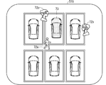
- FIG. 7 is a diagram showing a display example of the CID 51b controlled by the sixth alarm set, and shows a display example when the vehicle is stopped in the parking lot.
- a pedestrian display object 72a, a display in use display object 72b, a voice in use display object 72c, and a vehicle display object 73 indicating a vehicle equipped with the alarm control device 1 are generated by the CID 51b. It is shown.
- the alarm control unit 12b performs alarm control using the alarm mode for each of the plurality of mobile terminals in parallel. May be good. Further, the alarm control unit 12b may make the relative position of the pedestrian display object 72a with respect to the vehicle display object 73 correspond to the positional relationship between the vehicle and the mobile terminal in the unused state. Similarly, the alarm control unit 12b may make the relative position of the display in use display object 72b with respect to the vehicle display object 73 correspond to the positional relationship between the vehicle and the mobile terminal in the display use state.
- the alarm control unit 12b may make the relative position of the voice in use display object 72c with respect to the vehicle display object 73 correspond to the positional relationship between the vehicle and the mobile terminal in the voice use state. Further, the various controls described in the fifth alarm set may be performed in the sixth alarm set.
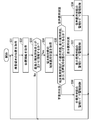
- FIG. 8 is a flowchart showing the operation of the alarm control device 1 according to the second embodiment.
- step S1 the vehicle-mounted camera 52 captures an image outside the vehicle under the control of the alarm control device 1.
- step S2 the information acquisition unit 11a acquires the positional relationship between the vehicle and the mobile terminal based on the image outside the vehicle taken by the vehicle-mounted camera 52.
- step S3 the contact determination unit 12a makes a contact determination based on the positional relationship acquired by the information acquisition unit 11a. If the contact determination determines that the vehicle and the terminal holder are in contact with each other, the process proceeds to step S4, and if the contact determination determines that the vehicle and the terminal owner do not contact each other, the process proceeds. Return to step S1.
- step S4 the terminal use state acquisition unit 11b acquires the terminal use state of the terminal owner based on the image outside the vehicle taken by the in-vehicle camera 52.
- step S5 the alarm control unit 12b determines whether the terminal use state acquired by the terminal use state acquisition unit 11b is a non-use state, a display use state, or a voice use state. If it is determined that the terminal use state is not in use, the process proceeds to step S6, and if it is determined that the terminal use state is the display use state, the process proceeds to step S7 and the terminal use state is changed. If it is determined that the voice is in use, the process proceeds to step S8.
- step S6 the alarm control unit 12b controls the alarm of the alarm device 51 on the vehicle side in the alarm mode associated with the unused state in advance. After that, the process returns to step S1.
- the alarm is controlled at a late timing as in the non-use state of the fourth alarm set, the alarm is controlled until the alarm is controlled from step S6 to step S1 and the contact determination process of step S3 is performed again. May be put on hold. According to such a configuration, for example, when an operation of avoiding contact between the vehicle and the terminal holder is performed by the time the alarm of step S6 is issued, unnecessary alarm can be suppressed. ..
- step S7 the alarm control unit 12b controls the alarm of the alarm device 51 on the vehicle side in the alarm mode associated with the display usage state in advance. After that, the process returns to step S1.
- step S8 the alarm control unit 12b controls the alarm of the alarm device 51 on the vehicle side in the alarm mode associated with the voice usage state in advance. After that, the process returns to step S1.
- ⁇ Summary of Embodiment 2> According to the alarm control device 1 according to the second embodiment as described above, when the contact is determined and the contact determination determines that the vehicle and the terminal owner are in contact with each other, the acquired terminal usage state is set. The alarm of the alarm device 51 on the vehicle side is controlled in the alarm mode associated in advance. According to such a configuration, the alarm of the alarm device 51 on the vehicle side can be appropriately issued.
- the timings of the alarms used in the plurality of alarm modes are different from each other as in the fourth alarm set. According to such a configuration, for example, if an operation of avoiding contact between the vehicle and the terminal holder is performed before the alarm is issued, the alarm can be stopped. Therefore, the alarm of the alarm device 51 on the vehicle side can be appropriately issued.
- the information acquisition unit 11a uses the image of the terminal owner outside the vehicle taken by the in-vehicle camera 52 as the relative movement information of the mobile terminal with respect to the vehicle as the relative movement information of the mobile terminal with respect to the vehicle. Acquire time series information of relative position. Then, the contact determination unit 12a makes a contact determination based on the positional relationship between the vehicle and the mobile terminal 2 acquired by the information acquisition unit 11a and the relative movement information of the mobile terminal.
- the contact determination unit 12a possesses the terminal of the vehicle and the mobile terminal 2 based on the positional relationship between the vehicle and the mobile terminal 2 and the future movement trajectory of the mobile terminal 2 predicted from the relative movement information of the mobile terminal 2. Determine if the person and the person pass in parallel with each other. Then, when the contact determination unit 12a determines that the vehicle and the terminal holder of the mobile terminal 2 pass in parallel with each other even if the distance between the vehicle and the mobile terminal 2 is relatively short, the vehicle and the terminal It is determined that the owners do not contact each other.
- the contact determination unit 12a determines the contact grace time, which is the time until contact occurs, based on the positional relationship between the vehicle and the mobile terminal 2 acquired by the information acquisition unit 11a and the relative movement information of the mobile terminal 2. You may estimate.
- FIG. 9 is a block diagram showing the configuration of the alarm control device 1 according to the second modification.
- the information acquisition unit 11a is connected to the GPS receiving device 53 that detects the position of the vehicle without being connected to the vehicle-mounted camera 52, and is connected to the communication unit 13 capable of communicating with the mobile terminal 2. It is the same as the alarm control device 1 of FIG. 2 except that it is connected.
- the information acquisition unit 11a acquires the position of the vehicle from the GPS receiving device 53, and obtains the position of the mobile terminal 2 detected by the terminal GPS receiving device (not shown) built in the mobile terminal 2 from the mobile terminal 2 to the communication unit 13. By acquiring through, the positional relationship between the vehicle and the mobile terminal 2 is acquired. Further, the information acquisition unit 11a acquires the time-series information of the position of the vehicle as the movement information of the vehicle, and acquires the time-series information of the position of the mobile terminal 2 as the movement information of the mobile terminal 2.
- the contact determination unit 12a is based on the positional relationship between the vehicle and the mobile terminal 2 acquired by the information acquisition unit 11a, the movement information of the vehicle, and the movement information of the mobile terminal 2, as in the modification 1 of the second embodiment. To make a contact judgment.
- the accuracy of the contact determination can be improved. Even if the contact determination unit 12a estimates the contact grace time, which is the time until contact occurs, based on the positional relationship between the vehicle and the mobile terminal 2, the movement information of the vehicle, and the movement information of the mobile terminal 2. good.
- FIG. 10 is a block diagram showing the configuration of the alarm control device 1 according to the third modification.
- the alarm control device 1 of FIG. 10 is similar to the alarm control device 1 of FIG. 9 except that the information acquisition unit 11a is connected to the steering position detection device 54 and the vehicle speed detection device 55.
- the information acquisition unit 11a acquires vehicle movement information based on the steering position of the vehicle detected by the steering position detection device 54 and the traveling speed of the vehicle detected by the vehicle speed detection device 55.
- the contact determination unit 12a is based on the positional relationship between the vehicle and the mobile terminal 2 acquired by the information acquisition unit 11a, the movement information of the vehicle, and the movement information of the mobile terminal 2, as in the modification 2 of the second embodiment. To make a contact judgment.
- the accuracy of the contact determination can be improved as in the second modification of the second embodiment.
- FIG. 11 is a block diagram showing the configuration of the alarm control device 1 according to the present modification 4.
- the terminal use state acquisition unit 11b is not connected to the in-vehicle camera 52 but is connected to the communication unit 13, and the mobile terminal 2 is provided with the terminal side acquisition unit 21b. It is the same as the alarm control device 1 of FIG. 10 except for the above point.
- the terminal-side acquisition unit 21b is included in the concept of the acquisition unit 11 in FIG.
- the terminal-side acquisition unit 21b acquires the terminal usage status from a control device (not shown) of the mobile terminal 2 that manages the terminal usage status.
- the terminal usage state according to the present modification 4 includes "screen in use”, “music in use”, “telephone communication in progress”, and "not in use”.
- the terminal use state acquisition unit 11b on the vehicle side acquires the terminal use state acquired by the terminal side acquisition unit 21b from the mobile terminal 2 via the communication unit 13.
- alarm modes are associated with each of "screen in use”, “music in use”, “telephone communication in progress”, and "not in use” in advance. Note that the alarm used in the alarm mode preliminarily associated with “telephone communication” is milder than the alarm used in the alarm mode preliminarily associated with, for example, "screen in use” and "music in use”. An alarm is used.
- the accuracy of the terminal usage state can be improved. Further, it is possible to control the alarm of the alarm device 51 on the vehicle side without using the vehicle-mounted camera 52.
- the terminal usage status is not limited to the above.
- the terminal usage state may be the type of application used in the mobile terminal 2, and the alarm control device 1 may be associated with an alarm mode in advance for each type of application.
- the terminal usage state may be the usage time of the terminal owner per unit time of the mobile terminal 2, and the alarm control device 1 is associated with the alarm mode in advance for each of the usage time divisions. May be good.
- the information acquisition unit 11a indicates the degree to which the terminal owner is paying attention to the vicinity of the terminal owner based on the image of the terminal owner outside the vehicle taken by the in-vehicle camera 52. Get the degree. For example, even if the information acquisition unit 11a recognizes that the terminal owner is down based on the image of the terminal owner, and acquires the peripheral attention level that becomes lower as the time during which the terminal owner continues to be down is longer. good. Further, for example, the information acquisition unit 11a may recognize the direction of the face of the terminal owner based on the image of the terminal owner, and may acquire the peripheral attention level that becomes lower as the frequency of the face change is smaller. .. Further, for example, the information acquisition unit 11a recognizes the facial expression and body orientation of the terminal holder based on the image of the terminal holder, and changes the peripheral attention level based on the facial expression and body orientation. You may.
- an alarm mode is previously associated with each combination of the terminal usage state and the peripheral attention level.
- an alarm used in an alarm mode preliminarily associated with one peripheral attention level is more than an alarm used in an alarm mode preliminarily associated with another peripheral attention level lower than the one peripheral attention level. Severe alarms are used.
- the alarm control unit 12b determines in the contact determination that the vehicle and the terminal owner come into contact with each other, the terminal usage status and the peripheral attention level acquired by the terminal usage status acquisition unit 11b from among the plurality of alarm modes Select the alarm mode pre-associated with the combination. According to the alarm control device 1 according to the present modification 5, an appropriate alarm mode can be used.
- the information acquisition unit 11a acquires the area where the vehicle and the mobile terminal 2 are located based on the positions of the vehicle and the mobile terminal 2 from the map information in which the area is predetermined.
- the area referred to here includes an unclear area where the distinction between the roadway and the sidewalk is not clear and a mixture of vehicles and pedestrians, and a clear area where the distinction between the roadway and the sidewalk is clear.
- Unclear areas include, for example, narrow streets without sidewalks, residential areas, parking lots, highway service areas and parking areas, and roads where the height difference between sidewalks and roadways is below a predetermined threshold. ..
- the clear area includes, for example, a road in which a roadway and a sidewalk are separated by a height difference or the like.
- an alarm mode is previously associated with each combination of the terminal usage state and the area.
- an alarm used in an alarm mode preliminarily associated with an unclear area uses a more severe alarm than an alarm used in an alarm mode preliminarily associated with a clear area.
- the combination of the terminal use state and the area acquired by the terminal use state acquisition unit 11b is selected from a plurality of alarm modes. Select a pre-associated alarm mode.
- the alarm control device 1 according to the present modification 6 for example, when the area where the vehicle and the mobile terminal 2 are located is an unclear area, it is possible to select an alarm mode in which the alarm timing is early. can. In this way, an appropriate alarm mode can be used.
- the alarm control unit 12b may control the issuance and stop of the alarm of the alarm device 51 on the vehicle side based on the area acquired by the information acquisition unit 11a and the result of the contact determination. For example, even if the alarm control unit 12b determines in the contact determination that the vehicle and the terminal holder come into contact with each other, if the area where the vehicle and the mobile terminal 2 are located is a clear area, the vehicle side The alarm of the alarm device 51 may be stopped.
- the information acquisition unit 11a acquires the traveling speed of the vehicle from the vehicle speed detection device 55.
- an alarm mode is previously associated with each combination of the terminal usage state and the traveling speed. For example, an alarm used in an alarm mode preliminarily associated with one travel speed is more severe than an alarm used in an alarm mode preliminarily associated with another travel speed greater than the one travel speed. Is used. In some cases, an alarm used in an alarm mode pre-associated with one travel speed is more severe than an alarm used in an alarm mode pre-associated with another travel speed less than the one travel speed. Alarm is used.
- the alarm control unit 12b determines in the contact determination that the vehicle and the terminal owner come into contact with each other, the combination of the terminal use state and the traveling speed acquired by the terminal use state acquisition unit 11b from among a plurality of alarm modes. Select the alarm mode associated with in advance.
- an alarm mode for issuing a severe alarm can be selected. In this way, an appropriate alarm mode can be used.
- the alarm control unit 12b may control the issuance and stop of the alarm of the alarm device 51 on the vehicle side based on the traveling speed acquired by the information acquisition unit 11a and the result of the contact determination. For example, even if the alarm control unit 12b determines in the contact determination that the vehicle and the terminal owner do not contact each other, if the traveling speed is equal to or less than a predetermined speed (for example, 10 km / h), the alarm control unit 12b may determine that the vehicle and the terminal owner do not contact each other. The alarm of the alarm device 51 on the vehicle side may be issued.
- a predetermined speed for example, 10 km / h
- FIG. 12 is a block diagram showing the configuration of the alarm control device 1 according to the third embodiment.
- the same or similar components as those described above will be designated by the same or similar reference numerals, and different components will be mainly described.
- the alarm control device 1, the HUD51a and the CID51b controlled by the alarm control device 1, and the voice output device 51c are provided in the vehicle.
- the alarm control device 1 is provided in the vehicle, and the terminal display device 51d controlled by the alarm control device 1 and the terminal voice output device 51e are provided in the mobile terminal 2. There is.
- the terminal display device 51d and the terminal voice output device 51e are not distinguished, these may be referred to as "alarm device 51 on the mobile terminal 2 side".
- the information acquisition unit 11a acquires the positional relationship between the vehicle and the mobile terminal 2 based on the image of the terminal owner outside the vehicle taken by the vehicle-mounted camera 52.
- the terminal use state acquisition unit 11b acquires the terminal use state of the terminal owner based on the image of the terminal owner outside the vehicle taken by the in-vehicle camera 52.
- the terminal use state according to the third embodiment includes a non-use state, a display use state (first state), and a voice use state (second state), as in the second embodiment.
- the contact determination unit 12a makes a contact determination to determine whether or not the vehicle and the terminal holder are in contact with each other based on the positional relationship acquired by the information acquisition unit 11a. Further, the contact determination unit 12a according to the third embodiment obtains an urgency indicating the degree of urgency to avoid contact between the vehicle and the terminal holder based on the positional relationship acquired by the information acquisition unit 11a.
- the plurality of alarm modes according to the third embodiment include three alarm modes that are previously associated with the non-use state, the display use state, and the voice use state. Then, in the alarm mode preliminarily associated with the display use state, the alarm is displayed on the terminal display device 51d, and in the alarm mode preliminarily associated with the voice use state, the alarm sound is output from the terminal voice output device 51e. NS.
- FIG. 13 is a diagram showing an example of a plurality of alarm modes used in the third embodiment.
- an alarm mode is previously associated with each combination of the terminal usage state and the urgency level.
- the alarm control unit 12b determines in the contact determination that the vehicle and the terminal owner come into contact with each other, the terminal use state and the contact determination unit 12a acquired by the terminal use state acquisition unit 11b from among the plurality of alarm modes. Select the alarm mode associated with the combination of urgency obtained in. Then, the alarm control unit 12b controls the alarm of the terminal display device 51d and the terminal voice output device 51e in the selected alarm mode.
- FIG. 14 is a diagram showing a display example of the terminal display device 51d controlled in some of the alarm modes of FIG. 13.
- the degree of urgency is low and the terminal is in a non-use state
- the alarm is not displayed on the terminal display device 51d, but is displayed by the application in use.
- the urgency is low and the terminal use state is the display use state
- a character indicating an alarm and a vehicle caution icon 75 are added to the display of the terminal display device 51d.
- the degree of urgency is high and the terminal usage status is the display usage status
- the character indicating the alarm and the position of the vehicle as seen from the terminal owner are shown on the entire screen of the terminal display device 51d.
- the vehicle display object 76 is displayed.
- FIG. 15 is a flowchart showing the operation of the alarm control device 1 according to the third embodiment.
- step S11 the vehicle-mounted camera 52 captures an image outside the vehicle under the control of the alarm control device 1.
- step S12 the information acquisition unit 11a acquires the positional relationship between the vehicle and the mobile terminal 2 based on the image outside the vehicle taken by the vehicle-mounted camera 52.
- step S13 the information acquisition unit 11a acquires the position and ID of the mobile terminal 2 via the communication unit 13.
- the alarm control device 1 compares the positional relationship acquired in step S12 with the position of the mobile terminal 2 acquired in step S13, so that the mobile terminal 2 and the mobile terminal 2 in the image captured in step S11 Associate with the acquired ID.
- step S14 the contact determination unit 12a makes a contact determination based on the positional relationship acquired by the information acquisition unit 11a. If the contact determination determines that the vehicle and the terminal holder are in contact with each other, the process proceeds to step S15, and if the contact determination determines that the vehicle and the terminal owner do not contact each other, the process proceeds. Return to step S11.
- step S15 the contact determination unit 12a calculates the degree of urgency based on the positional relationship acquired by the information acquisition unit 11a.
- the operation of step S15 may be performed in parallel with the operation of step S14.
- step S16 the terminal use state acquisition unit 11b acquires the terminal use state of the terminal owner based on the image outside the vehicle taken by the in-vehicle camera 52.
- step S17 the alarm control unit 12b is associated in advance with a combination of the terminal use state acquired by the terminal use state acquisition unit 11b and the urgency obtained by the contact determination unit 12a from among the plurality of alarm modes. Select an alarm mode.
- step S18 the alarm control unit 12b transmits a control signal for controlling the alarm of the alarm device 51 on the mobile terminal 2 side to the mobile terminal 2 in the alarm mode selected in step S17.
- the control signal includes the ID acquired in step S13. After that, the process returns to step S11.
- the alarm control device 1 when the contact is determined and the contact determination determines that the vehicle and the terminal owner are in contact with each other, the acquired terminal usage state is set.
- the alarm of the alarm device 51 on the mobile terminal 2 side is controlled in the alarm mode associated in advance. For example, when the terminal use state is the display use state, an alarm is displayed on the terminal display device 51d, and when the terminal use state is the display use state, the alarm sound is output from the terminal voice output device 51e. NS. According to such a configuration, the alarm of the alarm device 51 on the mobile terminal 2 side can be appropriately issued.
- each modification of the second embodiment may be applied.
- the information acquisition unit 11a may acquire the vehicle position information and the movement information from the GPS receiving device 53.
- the position information and movement information of the mobile terminal 2 may be acquired from the mobile terminal 2.
- the information acquisition unit 11a acquires the peripheral attention level based on the image of the terminal owner outside the vehicle taken by the vehicle-mounted camera 52. You may. Then, the alarm control unit 12b may select the alarm mode to be used for the alarm device 51 on the mobile terminal 2 side from the plurality of alarm modes in consideration of the peripheral attention level. The alarm control unit 12b may control the issuance and stop of the alarm of the alarm device 51 on the vehicle side based on the peripheral attention level acquired by the information acquisition unit 11a and the result of the contact determination.
- the alarm control unit 12b determines in the contact determination that the vehicle and the terminal owner come into contact with each other, if the peripheral attention level is equal to or higher than a predetermined threshold value, the alarm control unit 12b is on the mobile terminal 2 side. The alarm of the alarm device 51 may be stopped.
- the terminal use state acquisition unit 11b obtains the terminal use state acquired by the terminal side acquisition unit 21b from the mobile terminal 2. It may be acquired via the communication unit 13. According to such a configuration, the accuracy of the terminal usage state can be improved. Further, as shown in FIG. 16, if the modified example 2 (FIG. 9) and the modified example 4 (FIG. 11) of the second embodiment are applied to the third embodiment, the vehicle-mounted camera 52 is not used and the vehicle side is used. The alarm of the alarm device 51 can be controlled.
- FIG. 17 is a block diagram showing the configuration of the alarm control device 1 according to the fourth embodiment.
- the same or similar components as those described above will be designated by the same or similar reference numerals, and different components will be mainly described.
- the alarm control device 1 and the alarm device 51 are provided in the vehicle.
- the alarm control device 1 is provided in the vehicle, and the alarm device 51 is provided in the mobile terminal 2.
- the alarm control device 1 and the alarm device 51 are provided in the mobile terminal 2.
- the vehicle is provided with a GPS receiving device 53 and an in-vehicle communication device 3 that transmits the position of the vehicle detected by the GPS receiving device 53 to the mobile terminal 2.
- the mobile terminal 2 includes an alarm control device 1, a terminal display device 51d, a terminal voice output device 51e, and a terminal GPS receiving device 57.
- the terminal display device 51d and the terminal audio output device 51e of FIG. 17 are the same as the terminal display device 51d and the terminal audio output device 51e described so far.
- the terminal GPS receiving device 57 connected to the alarm control device 1 detects the position of the mobile terminal 2.
- the alarm control device 1 of FIG. 17 includes an information acquisition unit 21a, a terminal side acquisition unit 21b, a contact determination unit 22a, an alarm control unit 22b, and a communication unit 23.
- the information acquisition unit 21a and the terminal side acquisition unit 21b are included in the concept of the acquisition unit 11 in FIG. 1, and the contact determination unit 22a and the alarm control unit 22b are included in the concept of the control unit 12 in FIG.
- the information acquisition unit 21a, the terminal side acquisition unit 21b, the contact determination unit 22a, and the alarm control unit 22b are the information acquisition unit 11a and the terminal use state acquisition unit 11b described in the second embodiment. It corresponds to the contact determination unit 12a and the alarm control unit 12b, respectively.
- the information acquisition unit 21a acquires the position of the vehicle detected by the GPS receiving device 53 on the vehicle side from the in-vehicle communication device 3 via the communication unit 23, and the position of the mobile terminal 2 detected by the terminal GPS receiving device 57. Acquires the positional relationship between the vehicle and the mobile terminal 2.
- the terminal-side acquisition unit 21b is the same as the terminal-side acquisition unit 21b described in the modified example 4 of the second embodiment, and is provided in the mobile terminal 2. Then, the terminal-side acquisition unit 21b acquires the terminal use state from a control device (not shown) of the mobile terminal 2 that manages the terminal use state.
- the contact determination unit 22a makes a contact determination to determine whether or not the vehicle and the terminal holder are in contact with each other based on the positional relationship acquired by the information acquisition unit 21a.
- the alarm control unit 22b determines in the contact determination that the vehicle and the terminal holder come into contact with each other, the alarm control unit 22b is associated in advance with the terminal usage state acquired by the terminal side acquisition unit 21b from among a plurality of alarm modes. Select an alarm mode. Then, the alarm control unit 22b controls the alarm of the terminal display device 51d and the terminal voice output device 51e in the selected alarm mode.
- FIG. 18 is a flowchart showing the operation of the vehicle device according to the fourth embodiment.
- step S21 the GPS receiving device 53 detects the position of the vehicle.
- step S22 the vehicle-mounted communication device 3 transmits the position of the vehicle detected in step S21 and the vehicle ID to the mobile terminal 2 in the vicinity of the vehicle. After that, the process returns to step S21.
- FIG. 19 is a flowchart showing the operation of the alarm control device 1 according to the fourth embodiment.
- step S31 the information acquisition unit 21a acquires the position of the mobile terminal 2 detected by the terminal GPS receiving device 57.
- step S32 the information acquisition unit 21a acquires (receives) the position and ID of the vehicle transmitted from the vehicle-mounted communication device 3 via the communication unit 13.
- the information acquisition unit 21a acquires the positional relationship between the vehicle and the mobile terminal 2.
- step S33 the contact determination unit 22a makes a contact determination based on the positional relationship acquired by the information acquisition unit 21a. If the contact determination determines that the vehicle and the terminal holder are in contact with each other, the process proceeds to step S34, and if the contact determination determines that the vehicle and the terminal owner do not contact each other, the process proceeds. Return to step S31.
- step S34 the terminal-side acquisition unit 21b acquires the terminal usage status of the terminal owner.
- step S35 the alarm control unit 22b determines whether the terminal use state acquired by the terminal side acquisition unit 21b is a non-use state, a display use state, or a voice use state. If it is determined that the terminal use state is not in use, the process proceeds to step S36, and if it is determined that the terminal use state is the display use state, the process proceeds to step S37 and the terminal use state is changed. If it is determined that the voice is in use, the process proceeds to step S38.
- step S36 the alarm control unit 22b controls the alarm of the alarm device 51 on the mobile terminal 2 side in the alarm mode associated with the unused state in advance. After that, the process returns to step S31.
- step S37 the alarm control unit 22b controls the alarm of the alarm device 51 on the mobile terminal 2 side in the alarm mode associated with the display usage state in advance. After that, the process returns to step S31.
- step S38 the alarm control unit 22b controls the alarm of the alarm device 51 on the mobile terminal 2 side in the alarm mode associated with the voice usage state in advance. After that, the process returns to step S31.
- each modification of the second embodiment may be applied to the fourth embodiment.
- the information acquisition unit 21a uses the time series of the vehicle positions detected by the GPS receiving device 53 as the vehicle movement information. Information may be acquired from the vehicle-mounted communication device 3 via the communication unit 13. Further, the information acquisition unit 21a may acquire time-series information of the position of the mobile terminal 2 from the terminal GPS receiving device 57 as the movement information of the mobile terminal 2. Then, the contact determination unit 22a may make a contact determination based on the positional relationship between the vehicle and the mobile terminal 2 acquired by the information acquisition unit 21a, the movement information of the vehicle, and the movement information of the mobile terminal 2.
- the alarm control device 1 and the alarm device 51 on the vehicle side are provided in the vehicle.
- the alarm control device 1 is provided in the vehicle, and the alarm device 51 on the mobile terminal 2 side is provided in the mobile terminal 2.
- the alarm control device 1 and the alarm device 51 on the mobile terminal 2 side are provided in the mobile terminal 2.
- the alarm control device 1 may be provided in the mobile terminal 2, and the alarm device 51 on the vehicle side may be provided in the vehicle.
- the acquisition unit 11 and the control unit 12 of FIG. 1 described above are hereinafter referred to as “acquisition unit 11 and the like”.
- the acquisition unit 11 and the like are realized by the processing circuit 81 shown in FIG. That is, the processing circuit 81 is acquired by the acquisition unit 11 and the acquisition unit 11 that acquire the positional relationship between the vehicle and the mobile terminal and the terminal usage state that is the usage state of the mobile terminal by the terminal owner of the mobile terminal.
- the terminal usage state acquired by the acquisition unit 11 is associated in advance from among the plurality of alarm modes.
- a control unit 12 for controlling the alarm of the alarm device 51 in the alarm mode is provided.
- Dedicated hardware may be applied to the processing circuit 81, or a processor that executes a program stored in the memory may be applied to the processing circuit 81.
- the processor corresponds to, for example, a central processing unit, a processing unit, an arithmetic unit, a microprocessor, a microcomputer, a DSP (Digital Signal Processor), and the like.
- the processing circuit 81 may be, for example, a single circuit, a composite circuit, a programmed processor, a parallel programmed processor, an ASIC (Application Specific Integrated Circuit), or an FPGA (Field Programmable Gate). Array), or a combination of these.
- Each of the functions of each part such as the acquisition unit 11 may be realized by a circuit in which processing circuits are dispersed, or the functions of each part may be collectively realized by one processing circuit.
- the processing circuit 81 When the processing circuit 81 is a processor, the functions of the acquisition unit 11 and the like are realized by combining with software and the like.
- the software or the like corresponds to, for example, software, firmware, or software and firmware.
- Software and the like are described as programs and stored in memory.
- the processor 82 applied to the processing circuit 81 realizes the functions of each part by reading and executing the program stored in the memory 83. That is, when the alarm control device 1 is executed by the processing circuit 81, the step of acquiring the positional relationship between the vehicle and the mobile terminal and the terminal usage state which is the usage state of the mobile terminal by the terminal owner of the mobile terminal.
- the terminal usage state acquired by the acquisition unit from among a plurality of alarm modes.
- a step of controlling an alarm of the alarm device 51 in an alarm mode associated with the above, and a memory 83 for storing a program to be executed as a result are provided.
- this program causes the computer to execute the procedure or method of the acquisition unit 11 or the like.
- the memory 83 is a non-volatile or non-volatile memory such as a RAM (RandomAccessMemory), a ROM (ReadOnlyMemory), a flash memory, an EPROM (ErasableProgrammableReadOnlyMemory), and an EEPROM (ElectricallyErasableProgrammableReadOnlyMemory). Volatile semiconductor memory, HDD (Hard Disk Drive), magnetic disk, flexible disk, optical disk, compact disk, mini disk, DVD (DigitalVersatileDisc), its drive device, etc., or any storage medium that will be used in the future. You may.
- RAM RandomAccessMemory
- ROM ReadOnlyMemory
- flash memory an EPROM (ErasableProgrammableReadOnlyMemory), and an EEPROM (ElectricallyErasableProgrammableReadOnlyMemory).
- Volatile semiconductor memory Volatile semiconductor memory, HDD (Hard Disk Drive), magnetic disk, flexible disk, optical disk, compact
- each function of the acquisition unit 11 and the like is realized by either hardware or software has been described above.
- the present invention is not limited to this, and a configuration may be configured in which a part of the acquisition unit 11 or the like is realized by dedicated hardware and another part is realized by software or the like.
- the acquisition unit 11 realizes its function by a processing circuit 81 as dedicated hardware, an interface, a receiver, and the like, and other than that, the processing circuit 81 as a processor 82 reads a program stored in the memory 83. It is possible to realize the function by executing it.
- the processing circuit 81 can realize each of the above-mentioned functions by hardware, software, or a combination thereof.
- the alarm control device 1 described above is installed in at least one of a vehicle device such as an in-vehicle infotainment device, a communication terminal including a mobile terminal such as a mobile phone, a smartphone and a tablet, and a vehicle device and a communication terminal. It can also be applied to an alarm control system constructed as a system by appropriately combining the functions of the application to be applied and the server. In this case, each function or each component of the alarm control device 1 described above may be dispersedly arranged in each device for constructing the system, or may be centrally arranged in any one of the devices. good.
- FIG. 22 is a block diagram showing the configuration of the server 91 according to this modification.
- the server 91 of FIG. 22 includes a communication unit 91a and a control unit 91b, and can perform wireless communication with the vehicle device 93 of the vehicle 92 and the mobile terminal 94.
- the communication unit 91a which is an acquisition unit, wirelessly communicates with at least one of the vehicle device 93 and the mobile terminal 94 to determine the positional relationship between the vehicle 92 and the mobile terminal 94 and to carry the mobile terminal 94 by the terminal owner. Receives the terminal usage status, which is the usage status of the terminal 94.
- the control unit 91b has the same function as the control unit 12 of FIG. 1 when a processor (not shown) of the server 91 or the like executes a program stored in a memory (not shown) of the server 91. That is, the control unit 91b makes a contact determination based on the positional relationship received by the communication unit 91a. Then, when the control unit 91b determines in the contact determination that the vehicle 92 and the terminal holder come into contact with each other, the control unit 91b is associated in advance with the terminal usage state received by the communication unit 91a from among the plurality of alarm modes. In the alarm mode, it generates a control signal to control the alarm of the alarm device.
- the alarm device referred to here is provided in at least one of the vehicle 92 and the mobile terminal 94. Then, the communication unit 91a transmits the control signal generated by the control unit 91b to at least one of the vehicle 92 and the mobile terminal 94. According to the server 91 configured in this way, the same effect as that of the alarm control device 1 described in the first embodiment can be obtained.
- 1 alarm control device 2 mobile terminal, 11 acquisition unit, 12 control unit, 21b terminal side acquisition unit, 51 alarm device.
Landscapes
- Engineering & Computer Science (AREA)
- Physics & Mathematics (AREA)
- General Physics & Mathematics (AREA)
- Automation & Control Theory (AREA)
- Mathematical Physics (AREA)
- Transportation (AREA)
- Mechanical Engineering (AREA)
- Traffic Control Systems (AREA)
Abstract
車両と携帯端末の端末所持者との接触に対する警報を適切に制御可能な技術を提供することを目的とする。警報制御装置は、車両と携帯端末との位置関係と、端末使用状態とを取得する取得部と、取得部で取得された位置関係に基づいて接触判定を行い、接触判定において車両と端末所持者とが互いに接触すると判定した場合に、複数の警報モードの中から、取得部で取得された端末使用状態に予め対応付けられた警報モードで警報装置の警報を制御する制御部とを備える。
Description
本開示は、警報制御装置及び警報制御方法に関する。
車両と歩行者とが衝突する可能性が高い場合に、警報を発報するシステムが知られている。例えば特許文献1では、車両と歩行者との位置関係に基づいて衝突の可能性があると判定した場合に、歩行者が所持する携帯端末から歩行者に警報を発報して注意を喚起する技術が提案されている。
しかしながら、特許文献1の技術では、歩行者が車両と衝突する可能性があることを十分認識している場合でも、車両と歩行者との位置関係に基づいて画一的に警報を発報するため、警報が歩行者にとって煩わしいことがあるという問題があった。一方、歩行者が携帯端末を使用し、歩行者の車両に対する注意力が低下している場合には、積極的に警報を発報することが望まれる。
そこで、本開示は、上記のような問題点を鑑みてなされたものであり、車両と携帯端末の端末所持者との接触に対する警報を適切に制御可能な技術を提供することを目的とする。
本開示に係る警報制御装置は、車両と携帯端末との位置関係と、携帯端末の端末所持者による携帯端末の使用状態である端末使用状態とを取得する取得部と、取得部で取得された位置関係に基づいて、車両と端末所持者とが互いに接触するか否かを判定する接触判定を行い、接触判定において車両と端末所持者とが互いに接触すると判定した場合に、複数の警報モードの中から、取得部で取得された端末使用状態に予め対応付けられた警報モードで警報装置の警報を制御する制御部とを備える。
本開示によれば、接触判定において車両と端末所持者とが互いに接触すると判定した場合に、複数の警報モードの中から、取得部で取得された端末使用状態に予め対応付けられた警報モードで警報装置の警報を制御する。このような構成によれば、車両と携帯端末の端末所持者との接触に対する警報を適切に制御することができる。
本開示の目的、特徴、局面及び利点は、以下の詳細な説明と添付図面とによって、より明白となる。
<実施の形態1>
図1は、本実施の形態1に係る警報制御装置1の構成を示すブロック図である。図1の警報制御装置1は、警報装置51と無線または有線によって通信可能に接続されており、警報装置51の警報を制御することが可能となっている。
図1は、本実施の形態1に係る警報制御装置1の構成を示すブロック図である。図1の警報制御装置1は、警報装置51と無線または有線によって通信可能に接続されており、警報装置51の警報を制御することが可能となっている。
警報装置51は、警報制御装置1の制御により、車両と携帯端末の端末所持者との衝突などの接触に対する警報を発報する。携帯端末は、例えば携帯電話、スマートフォン、及びタブレットなどを含む。端末所持者は、歩行者であってもよいし、自転車などの乗り手であってもよい。
実施の形態2などで説明するように、警報装置51は、表示よって警報を発報する表示装置を含んでもよいし、音声出力によって警報音や警報内容を発報する音声出力装置を含んでもよい。また、警報制御装置1及び警報装置51は、車両に設けられてもよいし、携帯端末に設けられてもよいし、車両と携帯端末とに分散されて設けられてもよい。加えて、図1の例では、警報装置51は警報制御装置1に備えられていないが、警報制御装置1に備えられてもよい。
図1の警報制御装置1は、取得部11と、制御部12とを備える。
取得部11は、車両と携帯端末との位置関係を取得する。車両と携帯端末との位置関係は、車両及び携帯端末のそれぞれの絶対位置(例えば経度及び緯度)であってもよいし、車両及び携帯端末の一方に対する他方の相対位置であってもよい。取得部11の上記機能には、例えば、車両及び携帯端末の一方で撮影された画像に基づいて他方の位置を取得する画像認識装置、車両及び携帯端末の位置を検出するGPS(Global Positioning System)受信装置などのGNSS(Global Navigation Satellite System)受信装置、車両及び携帯端末の一方に設けられて他方から位置を受信する通信装置、並びに、これらのインターフェースの少なくともいずれかが用いられる。
また取得部11は、携帯端末の端末所持者による携帯端末の使用状態である端末使用状態を取得する。取得部11の上記機能には、例えば、車両で撮影された端末所持者の画像に基づいて端末使用状態を取得する画像認識装置、携帯端末の制御装置から端末使用状態を取得する通信装置、及び、これらのインターフェースの少なくともいずれかが用いられる。
制御部12は、取得部11で取得された位置関係に基づいて、車両と端末所持者とが互いに接触するか否かを判定する接触判定を行う。また制御部12は、接触判定において車両と端末所持者とが互いに接触すると判定した場合に、複数の警報モードの中から、取得部11で取得された端末使用状態に予め対応付けられた警報モードで警報装置51の警報を制御する。
<実施の形態1のまとめ>
以上のような本実施の形態1に係る警報制御装置1によれば、接触判定を行い、その接触判定で車両と端末所持者とが互いに接触すると判定した場合に、取得された端末使用状態に予め対応付けられた警報モードで警報装置51の警報を制御する。このような構成によれば、車両と端末所持者とが互いに接触すると判定された場合であっても、端末所持者が携帯端末を使用しておらず、端末所持者の車両に対する注意力が比較的高い場合には、軽度の警報の発報や警報の停止を行うことができる。一方、端末所持者が携帯端末を使用しており、端末所持者の車両に対する注意力が比較的低い場合には重度の警報の発報を行うことができる。このため、車両と携帯端末の端末所持者との接触に対する警報を適切に行うことができる。さらに、警報の発報を適切に抑制することによって、警報に用いる消費電力の低減化も期待できる。
以上のような本実施の形態1に係る警報制御装置1によれば、接触判定を行い、その接触判定で車両と端末所持者とが互いに接触すると判定した場合に、取得された端末使用状態に予め対応付けられた警報モードで警報装置51の警報を制御する。このような構成によれば、車両と端末所持者とが互いに接触すると判定された場合であっても、端末所持者が携帯端末を使用しておらず、端末所持者の車両に対する注意力が比較的高い場合には、軽度の警報の発報や警報の停止を行うことができる。一方、端末所持者が携帯端末を使用しており、端末所持者の車両に対する注意力が比較的低い場合には重度の警報の発報を行うことができる。このため、車両と携帯端末の端末所持者との接触に対する警報を適切に行うことができる。さらに、警報の発報を適切に抑制することによって、警報に用いる消費電力の低減化も期待できる。
<実施の形態2>
図2は、本実施の形態2に係る警報制御装置1の構成を示すブロック図である。以下、本実施の形態2に係る構成要素のうち、上述の構成要素と同じまたは類似する構成要素については同じまたは類似する参照符号を付し、異なる構成要素について主に説明する。
図2は、本実施の形態2に係る警報制御装置1の構成を示すブロック図である。以下、本実施の形態2に係る構成要素のうち、上述の構成要素と同じまたは類似する構成要素については同じまたは類似する参照符号を付し、異なる構成要素について主に説明する。
図2の警報制御装置1は、HUD(Head-Up Display)51a、CID(Center Information Display)51b、音声出力装置51c、及び、車載カメラ52と無線または有線によって通信可能に接続されている。本実施の形態2では、警報制御装置1は、車載インフォテインメント装置などに適用され、図2の構成要素は、車両に設けられているものとする。
HUD51aは、例えば、表示オブジェクトを、車両外の風景に付随させて車両のウィンドシールド(フロントガラス)に投影表示する装置である。CID51bは、例えば、インストルメントパネル中央に設けられた表示装置である。音声出力装置51cは、警報音を出力する装置である。HUD51a、CID51b、及び、音声出力装置51cは、図1の警報装置51の概念に含まれる。
以下の説明では、HUD51a、CID51b、及び、音声出力装置51cを区別しない場合には、これらを「車両側の警報装置51」と記すこともある。また、車両に設けられた上記の表示装置及び音声出力装置と区別するために、以下の説明では便宜上、携帯端末に設けられた表示装置を「端末表示装置」と記すこともあり、携帯端末に設けられた音声出力装置を「端末音声出力装置」と記すこともある。
車載カメラ52は、車両外の画像を撮影する。
<警報制御装置の構成>
図2の警報制御装置1は、情報取得部11aと、端末使用状態取得部11bと、接触判定部12aと、警報制御部12bとを備える。情報取得部11a及び端末使用状態取得部11bは、図1の取得部11の概念に含まれ、接触判定部12a及び警報制御部12bは、図1の制御部12の概念に含まれる。
図2の警報制御装置1は、情報取得部11aと、端末使用状態取得部11bと、接触判定部12aと、警報制御部12bとを備える。情報取得部11a及び端末使用状態取得部11bは、図1の取得部11の概念に含まれ、接触判定部12a及び警報制御部12bは、図1の制御部12の概念に含まれる。
情報取得部11aは、車載カメラ52で撮影された車両外の端末所持者の画像に基づいて画像認識を行うことにより、車両に対する端末所持者の相対位置を、車両と携帯端末との位置関係として取得する。
端末使用状態取得部11bは、車載カメラ52で撮影された車両外の端末所持者の画像に基づいて画像認識を行うことにより、端末所持者の端末使用状態を取得する。本実施の形態2に係る端末使用状態は、端末所持者が携帯端末を使用していない不使用状態と、端末所持者が端末表示装置の表示を見ている表示使用状態(第1状態)と、端末所持者が端末音声出力装置からの音声を聞いている音声使用状態(第2状態)とを含む。表示使用状態は、端末所持者が端末表示装置の表示を直接見ている状態、及び、端末所持者が端末表示装置の表示をヘッドマウントディスプレイを介して見ている状態などを含む。音声使用状態は、端末所持者が端末音声出力装置からの音声を直接聞いている状態、及び、端末所持者が端末音声出力装置からの音声をヘッドホンを介して聞いている状態などを含む。
接触判定部12aは、情報取得部11aで取得された位置関係に基づいて、車両と端末所持者とが互いに接触するか否かを判定する接触判定を行う。例えば、接触判定部12aは、車両の位置と端末所持者の位置との間の距離が予め定められた閾値以下である場合に、車両と端末所持者とが互いに接触すると判定する。
警報制御部12bは、接触判定において車両と端末所持者とが互いに接触すると判定した場合に、複数の警報モードの中から、端末使用状態取得部11bで取得された端末使用状態に予め対応付けられた警報モードを選択する。そして、警報制御部12bは、選択した警報モードでHUD51a、CID51b及び音声出力装置51cの警報を制御する。
なお、画像表示タイミング及び音声出力タイミングのような、複数の警報モードで用いられる警報のタイミングは互いに異なっていてもよい。また、画像の大きさ及び音声の大きさのような、複数の警報モードで用いられる警報の大きさは互いに異なっていてもよい。また、画像の内容及び音声の内容のような、複数の警報モードで用いられる警報の内容は互いに異なっていてもよい。また、複数の警報モードで用いられる装置の組み合わせは互いに異なっていてもよい。ここでいう装置の組み合わせは、HUD51a、CID51b及び音声出力装置51cの組み合わせであってもよいし、音声出力装置51cの左チャンネル及び右チャンネルの組み合わせであってもよい。以上を組み合わせて、複数の警報モードにおいて、警報のタイミング、大きさ、内容、装置の組み合わせの少なくともいずれか1つが互いに異なっていてもよい。
図3は、本実施の形態2で用いる複数の警報モードの一例を示す図である。本実施の形態2では、警報制御装置1において、未使用状態、表示使用状態、及び、音声使用状態のそれぞれに警報モードが予め対応付けられており、これら3つの警報モードに対して1つの警報セットが規定されている。
図3の例では6つの警報セットが規定されており、警報制御部12bは、例えば車両のユーザなどによって選択された1つの警報セットの3つの警報モードのいずれかで、HUD51a、CID51b及び音声出力装置51cの警報を制御する。以下、6つの警報セットのうちのいくつかの警報セットについて説明する。
<第2警報セット>
端末使用状態が不使用状態である場合、警報制御部12bは、不使用状態に予め対応付けられた警報モードで制御を行う。これにより、警報制御部12bは、「歩行者注意」という音声を音声出力装置51cに出力させる制御を行う。
端末使用状態が不使用状態である場合、警報制御部12bは、不使用状態に予め対応付けられた警報モードで制御を行う。これにより、警報制御部12bは、「歩行者注意」という音声を音声出力装置51cに出力させる制御を行う。
端末使用状態が表示使用状態である場合、警報制御部12bは、表示使用状態に予め対応付けられた警報モードで制御を行う。これにより、警報制御部12bは、図4に示すような携帯端末を示す表示使用中表示オブジェクト71をHUD51aに表示させる制御を行う。図4の表示使用中表示オブジェクト71は、端末表示装置の表示を見ている端末所持者に付随するように、車両のウィンドシールド71aに投影表示される表示オブジェクトである。また、図3に示すように、警報制御部12bは、「表示使用中歩行者」という音声を音声出力装置51cに出力させる制御を行う。
端末使用状態が音声使用状態である場合、警報制御部12bは、音声使用状態に予め対応付けられた警報モードで制御を行う。これにより図示しないが、警報制御部12bは、端末音声出力装置の音声を聞いている端末所持者に付随し、ヘッドホンを示す音声使用中表示オブジェクトをHUD51aに表示させる制御を行う。また、警報制御部12bは、「音声使用中歩行者」という音声を音声出力装置51cに出力させる制御を行う。
<第4警報セット>
端末使用状態が不使用状態である場合に、警報制御部12bは、遅いタイミングで「歩行者注意」という音声を音声出力装置51cに出力させる制御を行う。端末使用状態が表示使用状態である場合に、警報制御部12bは、早いタイミングで「表示使用中歩行者」という音声を音声出力装置51cに出力させる制御を行う。端末使用状態が音声使用状態である場合に、警報制御部12bは、遅いタイミングと早いタイミングとの間のタイミングで「音声使用中歩行者」という音声を音声出力装置51cに出力させる制御を行う。
端末使用状態が不使用状態である場合に、警報制御部12bは、遅いタイミングで「歩行者注意」という音声を音声出力装置51cに出力させる制御を行う。端末使用状態が表示使用状態である場合に、警報制御部12bは、早いタイミングで「表示使用中歩行者」という音声を音声出力装置51cに出力させる制御を行う。端末使用状態が音声使用状態である場合に、警報制御部12bは、遅いタイミングと早いタイミングとの間のタイミングで「音声使用中歩行者」という音声を音声出力装置51cに出力させる制御を行う。
<第5警報セット>
端末使用状態が不使用状態、表示使用状態、及び、音声使用状態である場合に、歩行者表示オブジェクト、表示使用中表示オブジェクト、及び、音声使用中表示オブジェクトがCID51bによってそれぞれ表示される。
端末使用状態が不使用状態、表示使用状態、及び、音声使用状態である場合に、歩行者表示オブジェクト、表示使用中表示オブジェクト、及び、音声使用中表示オブジェクトがCID51bによってそれぞれ表示される。
図5に、歩行者表示オブジェクト、表示使用中表示オブジェクト、及び、音声使用中表示オブジェクトの一例を示す。図5の歩行者表示オブジェクトは、端末所持者が携帯端末を使用していない状態を示す。図5の表示使用中表示オブジェクトは、端末所持者が携帯端末の表示を直接見ている状態を示す。図5の音声使用中表示オブジェクトは、端末所持者が携帯端末からの音声を直接聞いている状態を示す。
図6に、歩行者表示オブジェクト、表示使用中表示オブジェクト、及び、音声使用中表示オブジェクトの別例を示す。図6の歩行者表示オブジェクトは、端末所持者が携帯端末を使用していない状態を示す。図6の表示使用中表示オブジェクトは、端末所持者が携帯端末の表示をヘッドマウントディスプレイを介して見ている状態を示す。図6の音声使用中表示オブジェクトは、端末所持者が携帯端末からの音声をヘッドホンを介して聞いている状態を示す。
警報制御部12bは、図5及び図6の表示オブジェクトのうち端末使用状態に対応する表示オブジェクトをCID51bに表示させる制御を行ってもよい。例えば、警報制御部12bは、ヘッドマウントディスプレイを介した表示使用を認識できた場合には図6の表示オブジェクトを表示し、ヘッドマウントディスプレイを介さない表示使用を認識できた場合には図5の表示オブジェクトを表示してもよい。例えば、警報制御部12bは、ヘッドホンを介した音声使用を認識できた場合には図6の表示オブジェクトを表示し、ヘッドホンを介さない音声使用を認識できた場合には図5の表示オブジェクトを表示してもよい。
同様に、警報制御部12bは、端末使用状態に対応する表示オブジェクトをHUD51aに表示させる制御を行ってもよい。また、警報制御部12bは、HUD51aでの表示オブジェクトの表示、及び、CID51bでの表示オブジェクトの表示を組み合わせてもよい。
<第6警報セット>
第6警報セットでは、第5警報セットと同様に、端末使用状態が不使用状態、表示使用状態、及び、音声使用状態である場合に、歩行者表示オブジェクト、表示使用中表示オブジェクト、及び、音声使用中表示オブジェクトがCID51bによってそれぞれ表示される。ただし、第6警報セットでは、これら表示オブジェクトに加えて、車両を示す車両表示オブジェクトもCID51bによって表示される。
第6警報セットでは、第5警報セットと同様に、端末使用状態が不使用状態、表示使用状態、及び、音声使用状態である場合に、歩行者表示オブジェクト、表示使用中表示オブジェクト、及び、音声使用中表示オブジェクトがCID51bによってそれぞれ表示される。ただし、第6警報セットでは、これら表示オブジェクトに加えて、車両を示す車両表示オブジェクトもCID51bによって表示される。
図7は、第6警報セットで制御されるCID51bの表示例を示す図であり、車両が駐車場に停車しているときの表示例を示している。図7に示すように、CID51bによって、歩行者表示オブジェクト72aと、表示使用中表示オブジェクト72bと、音声使用中表示オブジェクト72cと、警報制御装置1が搭載された車両を示す車両表示オブジェクト73とが示されている。
図7の例に示すように、画像処理によって複数の携帯端末が認識された場合に、警報制御部12bは、複数の携帯端末にそれぞれについて警報モードを用いた警報の制御を並列的に行ってもよい。また、警報制御部12bは、車両表示オブジェクト73に対する歩行者表示オブジェクト72aの相対位置を、車両と、不使用状態の携帯端末との位置関係に対応させてもよい。同様に、警報制御部12bは、車両表示オブジェクト73に対する表示使用中表示オブジェクト72bの相対位置を、車両と、表示使用状態の携帯端末との位置関係に対応させてもよい。同様に、警報制御部12bは、車両表示オブジェクト73に対する音声使用中表示オブジェクト72cの相対位置を、車両と、音声使用状態の携帯端末との位置関係に対応させてもよい。また、第5警報セットで説明した各種制御が、第6警報セットで行われてもよい。
<動作>
図8は、本実施の形態2に係る警報制御装置1の動作を示すフローチャートである。
図8は、本実施の形態2に係る警報制御装置1の動作を示すフローチャートである。
ステップS1にて、警報制御装置1の制御によって、車載カメラ52は車両外の画像を撮影する。
ステップS2にて、情報取得部11aは、車載カメラ52で撮影された車両外の画像に基づいて、車両と携帯端末との位置関係を取得する。
ステップS3にて、接触判定部12aは、情報取得部11aで取得された位置関係に基づいて接触判定を行う。接触判定にて車両と端末所持者とが互いに接触すると判定された場合には処理がステップS4に進み、接触判定にて車両と端末所持者とが互いに接触しないと判定された場合には処理がステップS1に戻る。
ステップS4にて、端末使用状態取得部11bは、車載カメラ52で撮影された車両外の画像に基づいて、端末所持者の端末使用状態を取得する。
ステップS5にて、警報制御部12bは、端末使用状態取得部11bで取得された端末使用状態が、不使用状態、表示使用状態、及び、音声使用状態のいずれであるかを判定する。端末使用状態が不使用状態であると判定された場合には処理がステップS6に進み、端末使用状態が表示使用状態であると判定された場合には処理がステップS7に進み、端末使用状態が音声使用状態であると判定された場合には処理がステップS8に進む。
ステップS6にて、警報制御部12bは、不使用状態に予め対応付けられた警報モードで車両側の警報装置51の警報を制御する。その後、処理がステップS1に戻る。なお、第4警報セットの不使用状態のように、遅いタイミングで警報が制御される場合には、ステップS6からステップS1に戻って再度のステップS3の接触判定の処理を行うまで、警報の制御を保留してもよい。このような構成によれば、例えば、ステップS6の警報が行われるまでに、車両と端末所持者との接触を回避する動作が行われた場合などには、不要な警報を抑制することができる。
ステップS7にて、警報制御部12bは、表示使用状態に予め対応付けられた警報モードで車両側の警報装置51の警報を制御する。その後、処理がステップS1に戻る。
ステップS8にて、警報制御部12bは、音声使用状態に予め対応付けられた警報モードで車両側の警報装置51の警報を制御する。その後、処理がステップS1に戻る。
<実施の形態2のまとめ>
以上のような本実施の形態2に係る警報制御装置1によれば、接触判定を行い、その接触判定で車両と端末所持者とが互いに接触すると判定した場合に、取得された端末使用状態に予め対応付けられた警報モードで車両側の警報装置51の警報を制御する。このような構成によれば、車両側の警報装置51の警報を適切に行うことができる。
以上のような本実施の形態2に係る警報制御装置1によれば、接触判定を行い、その接触判定で車両と端末所持者とが互いに接触すると判定した場合に、取得された端末使用状態に予め対応付けられた警報モードで車両側の警報装置51の警報を制御する。このような構成によれば、車両側の警報装置51の警報を適切に行うことができる。
また本実施の形態2では、第4警報セットのように複数の警報モードで用いられる警報のタイミングが互いに異なる。このような構成によれば、例えば警報が行われるまでに、車両と端末所持者との接触を回避する動作が行われた場合には、警報を停止することができる。このため、車両側の警報装置51の警報を適切に行うことができる。
<実施の形態2の変形例1>
本変形例1では、情報取得部11aは、車載カメラ52で撮影された車両外の端末所持者の画像に基づいて、車両に対する携帯端末の移動情報である相対移動情報として、車両に対する携帯端末の相対位置の時系列情報を取得する。そして、接触判定部12aは、情報取得部11aで取得された車両及び携帯端末2の位置関係と、携帯端末の相対移動情報とに基づいて接触判定を行う。
本変形例1では、情報取得部11aは、車載カメラ52で撮影された車両外の端末所持者の画像に基づいて、車両に対する携帯端末の移動情報である相対移動情報として、車両に対する携帯端末の相対位置の時系列情報を取得する。そして、接触判定部12aは、情報取得部11aで取得された車両及び携帯端末2の位置関係と、携帯端末の相対移動情報とに基づいて接触判定を行う。
例えば、接触判定部12aは、車両及び携帯端末2の位置関係と、携帯端末2の相対移動情報から予測される携帯端末2の将来の移動軌跡とに基づいて、車両と携帯端末2の端末所持者とが互いに平行に通り過ぎるか否かを判定する。そして、接触判定部12aは、車両と携帯端末2との間の距離が比較的短くても、車両と携帯端末2の端末所持者とが互いに平行に通り過ぎると判定した場合には、車両と端末所持者とが互いに接触しないと判定する。
このような本変形例1に係る警報制御装置1によれば、接触判定の精度を高めることができる。なお、接触判定部12aは、情報取得部11aで取得された車両及び携帯端末2の位置関係、並びに、携帯端末2の相対移動情報に基づいて、接触が生じるまでの時間である接触猶予時間を推定してもよい。
<実施の形態2の変形例2>
図9は、本変形例2に係る警報制御装置1の構成を示すブロック図である。図9の警報制御装置1は、情報取得部11aが、車載カメラ52と接続されずに、車両の位置を検出するGPS受信装置53と接続され、かつ携帯端末2と通信可能な通信部13と接続されている点を除けば図2の警報制御装置1と同様である。
図9は、本変形例2に係る警報制御装置1の構成を示すブロック図である。図9の警報制御装置1は、情報取得部11aが、車載カメラ52と接続されずに、車両の位置を検出するGPS受信装置53と接続され、かつ携帯端末2と通信可能な通信部13と接続されている点を除けば図2の警報制御装置1と同様である。
情報取得部11aは、GPS受信装置53から車両の位置を取得し、携帯端末2に内蔵された図示しない端末GPS受信装置で検出された携帯端末2の位置を、携帯端末2から通信部13を介して取得することにより、車両及び携帯端末2の位置関係を取得する。また、情報取得部11aは、車両の移動情報として、車両の位置の時系列情報を取得し、携帯端末2の移動情報として、携帯端末2の位置の時系列情報を取得する。
接触判定部12aは、実施の形態2の変形例1と同様に、情報取得部11aで取得された車両及び携帯端末2の位置関係、車両の移動情報、並びに、携帯端末2の移動情報に基づいて接触判定を行う。
このような本変形例2に係る警報制御装置1によれば、接触判定の精度を高めることができる。なお、接触判定部12aは、車両及び携帯端末2の位置関係、車両の移動情報、並びに、携帯端末2の移動情報に基づいて、接触が生じるまでの時間である接触猶予時間を推定してもよい。
<実施の形態2の変形例3>
図10は、本変形例3に係る警報制御装置1の構成を示すブロック図である。図10の警報制御装置1は、情報取得部11aが、ステアリング位置検出装置54及び車両速度検出装置55と接続されている点を除けば図9の警報制御装置1と同様である。
図10は、本変形例3に係る警報制御装置1の構成を示すブロック図である。図10の警報制御装置1は、情報取得部11aが、ステアリング位置検出装置54及び車両速度検出装置55と接続されている点を除けば図9の警報制御装置1と同様である。
情報取得部11aは、ステアリング位置検出装置54で検出された車両のステアリング位置と、車両速度検出装置55で検出された車両の走行速度とに基づいて、車両の移動情報を取得する。接触判定部12aは、実施の形態2の変形例2と同様に、情報取得部11aで取得された車両及び携帯端末2の位置関係、車両の移動情報、並びに、携帯端末2の移動情報に基づいて接触判定を行う。このような本変形例3に係る警報制御装置1によれば、実施の形態2の変形例2と同様に接触判定の精度を高めることができる。
<実施の形態2の変形例4>
図11は、本変形例4に係る警報制御装置1の構成を示すブロック図である。図11の警報制御装置1は、端末使用状態取得部11bが、車載カメラ52と接続されずに通信部13と接続されている点、及び、携帯端末2に端末側取得部21bが設けられている点を除けば図10の警報制御装置1と同様である。
図11は、本変形例4に係る警報制御装置1の構成を示すブロック図である。図11の警報制御装置1は、端末使用状態取得部11bが、車載カメラ52と接続されずに通信部13と接続されている点、及び、携帯端末2に端末側取得部21bが設けられている点を除けば図10の警報制御装置1と同様である。
端末側取得部21bは、図1の取得部11の概念に含まれる。端末側取得部21bは、端末使用状態を管理している携帯端末2の制御装置(図示せず)などから、端末使用状態を取得する。本変形例4に係る端末使用状態は、「画面使用中」、「音楽使用中」、「電話通信中」、及び、「使用なし」を含む。
車両側の端末使用状態取得部11bは、端末側取得部21bで取得された端末使用状態を、携帯端末2から通信部13を介して取得する。本変形例4では、警報制御装置1において、「画面使用中」、「音楽使用中」、「電話通信中」、及び、「使用なし」のそれぞれに警報モードが予め対応付けられている。なお、「電話通信中」に予め対応付けられた警報モードで用いられる警報には、例えば「画面使用中」及び「音楽使用中」に予め対応付けられた警報モードで用いられる警報よりも軽度の警報が用いられる。
このような本変形例4に係る警報制御装置1によれば、端末使用状態の精度を高めることができる。また、車載カメラ52を用いずに車両側の警報装置51の警報を制御することができる。
なお、端末使用状態は、上記に限ったものではない。例えば、端末使用状態は、携帯端末2で使用されているアプリケーションの種類であってもよく、警報制御装置1において、当該アプリケーションの種類のそれぞれに警報モードが予め対応付けられてもよい。また例えば、端末使用状態は、携帯端末2の単位時間当たりの端末所持者の使用時間であってもよく、警報制御装置1において、当該使用時間の区分のそれぞれに警報モードが予め対応付けられてもよい。
<実施の形態2の変形例5>
本変形例5では、情報取得部11aは、車載カメラ52で撮影された車両外の端末所持者の画像に基づいて、端末所持者が端末所持者の周辺を注意している度合を示す周辺注意度を取得する。例えば、情報取得部11aは、端末所持者の画像に基づいて、端末所持者が俯いていることを画像認識し、俯いた状態が継続する時間が長いほど低くなる周辺注意度を取得してもよい。また例えば、情報取得部11aは、端末所持者の画像に基づいて、端末所持者の顔の向きを画像認識し、顔の向きが変わる頻度が小さいほど低くなる周辺注意度を取得してもよい。また例えば、情報取得部11aは、端末所持者の画像に基づいて、端末所持者の顔の表情及び体の向きを画像認識し、顔の表情及び体の向きに基づいて周辺注意度を変更してもよい。
本変形例5では、情報取得部11aは、車載カメラ52で撮影された車両外の端末所持者の画像に基づいて、端末所持者が端末所持者の周辺を注意している度合を示す周辺注意度を取得する。例えば、情報取得部11aは、端末所持者の画像に基づいて、端末所持者が俯いていることを画像認識し、俯いた状態が継続する時間が長いほど低くなる周辺注意度を取得してもよい。また例えば、情報取得部11aは、端末所持者の画像に基づいて、端末所持者の顔の向きを画像認識し、顔の向きが変わる頻度が小さいほど低くなる周辺注意度を取得してもよい。また例えば、情報取得部11aは、端末所持者の画像に基づいて、端末所持者の顔の表情及び体の向きを画像認識し、顔の表情及び体の向きに基づいて周辺注意度を変更してもよい。
本変形例5では、警報制御装置1において、端末使用状態と周辺注意度との組み合わせのそれぞれに警報モードが予め対応付けられている。例えば、一の周辺注意度に予め対応付けられた警報モードで用いられる警報には、当該一の周辺注意度よりも低い別の周辺注意度に予め対応付けられた警報モードで用いられる警報よりも重度の警報が用いられる。
警報制御部12bは、接触判定において車両と端末所持者とが互いに接触すると判定した場合に、複数の警報モードの中から、端末使用状態取得部11bで取得された端末使用状態及び周辺注意度の組み合わせに予め対応付けられた警報モードを選択する。このような本変形例5に係る警報制御装置1によれば、適切な警報モードを用いることができる。
<実施の形態2の変形例6>
本変形例6では、情報取得部11aは、区域が予め規定された地図情報から、車両及び携帯端末2の位置に基づいて、車両及び携帯端末2が位置する区域を取得する。ここでいう区域は、車道と歩道との区別が明確でなく車両と歩行者とが混在する不明確区域と、車道と歩道との区別が明確である明確区域とを含む。不明確区域は、例えば、歩道がない細街路、住宅地、駐車場、高速道路のサービスエリア及びパーキングエリア、並びに、歩道と車道との高低差が予め定められた閾値以下である道路などを含む。明確区域は、例えば、車道と歩道とが高低差などによって区分されている道路などを含む。
本変形例6では、情報取得部11aは、区域が予め規定された地図情報から、車両及び携帯端末2の位置に基づいて、車両及び携帯端末2が位置する区域を取得する。ここでいう区域は、車道と歩道との区別が明確でなく車両と歩行者とが混在する不明確区域と、車道と歩道との区別が明確である明確区域とを含む。不明確区域は、例えば、歩道がない細街路、住宅地、駐車場、高速道路のサービスエリア及びパーキングエリア、並びに、歩道と車道との高低差が予め定められた閾値以下である道路などを含む。明確区域は、例えば、車道と歩道とが高低差などによって区分されている道路などを含む。
本変形例6では、警報制御装置1において、端末使用状態と区域との組み合わせのそれぞれに警報モードが予め対応付けられている。例えば、不明確区域に予め対応付けられた警報モードで用いられる警報には、明確区域に予め対応付けられた警報モードで用いられる警報よりも重度の警報が用いられる。
警報制御部12bは、接触判定において車両と端末所持者とが互いに接触すると判定した場合に、複数の警報モードの中から、端末使用状態取得部11bで取得された端末使用状態及び区域の組み合わせに予め対応付けられた警報モードを選択する。このような本変形例6に係る警報制御装置1によれば、例えば、車両及び携帯端末2が位置する区域が不明確区域である場合には、警報のタイミングが早い警報モードを選択することができる。このように、適切な警報モードを用いることができる。
なお、警報制御部12bは、情報取得部11aで取得された区域と、接触判定の結果とに基づいて、車両側の警報装置51の警報の発報及び停止を制御してもよい。例えば、警報制御部12bは、接触判定において車両と端末所持者とが互いに接触すると判定した場合であっても、車両及び携帯端末2が位置する区域が明確区域である場合には、車両側の警報装置51の警報を停止させてもよい。
<実施の形態2の変形例7>
本変形例7では、情報取得部11aは、車両速度検出装置55から車両の走行速度を取得する。本変形例7では、警報制御装置1において、端末使用状態と走行速度との組み合わせのそれぞれに警報モードが予め対応付けられている。例えば、一の走行速度に予め対応付けられた警報モードで用いられる警報には、当該一の走行速度よりも大きい別の走行速度に予め対応付けられた警報モードで用いられる警報よりも重度の警報が用いられる。場合によっては、一の走行速度に予め対応付けられた警報モードで用いられる警報には、当該一の走行速度よりも小さい別の走行速度に予め対応付けられた警報モードで用いられる警報よりも重度の警報が用いられる。
本変形例7では、情報取得部11aは、車両速度検出装置55から車両の走行速度を取得する。本変形例7では、警報制御装置1において、端末使用状態と走行速度との組み合わせのそれぞれに警報モードが予め対応付けられている。例えば、一の走行速度に予め対応付けられた警報モードで用いられる警報には、当該一の走行速度よりも大きい別の走行速度に予め対応付けられた警報モードで用いられる警報よりも重度の警報が用いられる。場合によっては、一の走行速度に予め対応付けられた警報モードで用いられる警報には、当該一の走行速度よりも小さい別の走行速度に予め対応付けられた警報モードで用いられる警報よりも重度の警報が用いられる。
警報制御部12bは、接触判定において車両と端末所持者とが互いに接触すると判定した場合に、複数の警報モードの中から、端末使用状態取得部11bで取得された端末使用状態及び走行速度の組み合わせに予め対応付けられた警報モードを選択する。
ここで、一般的に、渋滞や細街路などで運転者からの見通しが悪い場合や、運転者が何かを探している場合などには、運転者は徐行運転を行う傾向にある。車両が徐行して、例えば時速10~15km程度で走行いる場合には歩行者が飛び出してくる可能性が高い。
本変形例7に係る警報制御装置1によれば、例えば、車両が徐行している場合に、重度の警報を発報する警報モードを選択することができる。このように、適切な警報モードを用いることができる。
なお、警報制御部12bは、情報取得部11aで取得された走行速度と、接触判定の結果とに基づいて、車両側の警報装置51の警報の発報及び停止を制御してもよい。例えば、警報制御部12bは、接触判定において車両と端末所持者とが互いに接触しないと判定した場合であっても、走行速度が予め定められた速度(例えば時速10km)以下である場合には、車両側の警報装置51の警報を発報させてもよい。
<実施の形態3>
図12は、本実施の形態3に係る警報制御装置1の構成を示すブロック図である。以下、本実施の形態3に係る構成要素のうち、上述の構成要素と同じまたは類似する構成要素については同じまたは類似する参照符号を付し、異なる構成要素について主に説明する。
図12は、本実施の形態3に係る警報制御装置1の構成を示すブロック図である。以下、本実施の形態3に係る構成要素のうち、上述の構成要素と同じまたは類似する構成要素については同じまたは類似する参照符号を付し、異なる構成要素について主に説明する。
実施の形態2では、警報制御装置1と、警報制御装置1によって制御されるHUD51a、CID51b、及び、音声出力装置51cとが、車両に設けられていた。これに対して本実施の形態3では、警報制御装置1が車両に設けられ、警報制御装置1によって制御される端末表示装置51d、及び、端末音声出力装置51eが、携帯端末2に設けられている。以下の説明では、端末表示装置51d、及び、端末音声出力装置51eを区別しない場合には、これらを「携帯端末2側の警報装置51」と記すこともある。
情報取得部11aは、実施の形態2と同様に、車載カメラ52で撮影された車両外の端末所持者の画像に基づいて、車両と携帯端末2との位置関係を取得する。
端末使用状態取得部11bは、実施の形態2と同様に、車載カメラ52で撮影された車両外の端末所持者の画像に基づいて、端末所持者の端末使用状態を取得する。本実施の形態3に係る端末使用状態は、実施の形態2と同様に、不使用状態と、表示使用状態(第1状態)と、音声使用状態(第2状態)とを含む。
接触判定部12aは、実施の形態2と同様に、情報取得部11aで取得された位置関係に基づいて、車両と端末所持者とが互いに接触するか否かを判定する接触判定を行う。また、本実施の形態3に係る接触判定部12aは、情報取得部11aで取得された位置関係に基づいて、車両と端末所持者との接触を回避する緊急の度合を示す緊急度を求める。
本実施の形態3に係る複数の警報モードは、不使用状態、表示使用状態、及び、音声使用状態に予め対応付けられた3つの警報モードを含む。そして、表示使用状態に予め対応付けられた警報モードでは、端末表示装置51dで警報が表示され、音声使用状態に予め対応付けられた警報モードでは、端末音声出力装置51eから警報の音声が出力される。
図13は、本実施の形態3で用いる複数の警報モードの一例を示す図である。図13の例では、警報制御装置1において、端末使用状態と緊急度との組み合わせのそれぞれに警報モードが予め対応付けられている。警報制御部12bは、接触判定において車両と端末所持者とが互いに接触すると判定した場合に、複数の警報モードの中から、端末使用状態取得部11bで取得された端末使用状態及び接触判定部12aで求めた緊急度の組み合わせに予め対応付けられた警報モードを選択する。そして、警報制御部12bは、選択した警報モードで端末表示装置51d、及び、端末音声出力装置51eの警報を制御する。
図14は、図13の警報モードのうちのいくつかの警報モードで制御される端末表示装置51dの表示例を示す図である。緊急度が小であり、端末使用状態が不使用状態である場合、端末表示装置51dには警報は表示されず、使用中のアプリケーションによる表示が行われる。緊急度が小であり、端末使用状態が表示使用状態である場合、端末表示装置51dの表示に、警報を示す文字と、車両注意アイコン75とが追加される。緊急度が大であり、端末使用状態が表示使用状態である場合、端末表示装置51dの画面全体に、警報を示す文字と、端末所持者(円の中心に対応)からみた車両の位置を示す車両表示オブジェクト76とが表示される。
<動作>
図15は、本実施の形態3に係る警報制御装置1の動作を示すフローチャートである。
図15は、本実施の形態3に係る警報制御装置1の動作を示すフローチャートである。
ステップS11にて、警報制御装置1の制御によって、車載カメラ52は車両外の画像を撮影する。
ステップS12にて、情報取得部11aは、車載カメラ52で撮影された車両外の画像に基づいて、車両と携帯端末2との位置関係を取得する。
ステップS13にて、情報取得部11aは、携帯端末2の位置及びIDを、通信部13を介して取得する。警報制御装置1は、ステップS12で取得された位置関係と、ステップS13で取得された携帯端末2の位置とを比較することにより、ステップS11で撮影された画像内の携帯端末2とステップS12で取得されたIDとを対応づける。
ステップS14にて、接触判定部12aは、情報取得部11aで取得された位置関係に基づいて接触判定を行う。接触判定にて車両と端末所持者とが互いに接触すると判定された場合には処理がステップS15に進み、接触判定にて車両と端末所持者とが互いに接触しないと判定された場合には処理がステップS11に戻る。
ステップS15にて、接触判定部12aは、情報取得部11aで取得された位置関係に基づいて緊急度を算出する。なお、このステップS15の動作は、ステップS14の動作と並行して行われてもよい。
ステップS16にて、端末使用状態取得部11bは、車載カメラ52で撮影された車両外の画像に基づいて、端末所持者の端末使用状態を取得する。
ステップS17にて、警報制御部12bは、複数の警報モードの中から、端末使用状態取得部11bで取得された端末使用状態及び接触判定部12aで求めた緊急度の組み合わせに予め対応付けられた警報モードを選択する。
ステップS18にて、警報制御部12bは、ステップS17で選択された警報モードで携帯端末2側の警報装置51の警報を制御するための制御信号を、当該携帯端末2に送信する。なお、携帯端末2を個別に制御するために、制御信号には、ステップS13で取得されたIDが含まれる。その後、処理がステップS11に戻る。
<実施の形態3のまとめ>
以上のような本実施の形態3に係る警報制御装置1によれば、接触判定を行い、その接触判定で車両と端末所持者とが互いに接触すると判定した場合に、取得された端末使用状態に予め対応付けられた警報モードで携帯端末2側の警報装置51の警報を制御する。例えば、端末使用状態が表示使用状態である場合には、端末表示装置51dで警報が表示され、端末使用状態が表示使用状態である場合には、端末音声出力装置51eから警報の音声が出力される。このような構成によれば、携帯端末2側の警報装置51の警報を適切に行うことができる。
以上のような本実施の形態3に係る警報制御装置1によれば、接触判定を行い、その接触判定で車両と端末所持者とが互いに接触すると判定した場合に、取得された端末使用状態に予め対応付けられた警報モードで携帯端末2側の警報装置51の警報を制御する。例えば、端末使用状態が表示使用状態である場合には、端末表示装置51dで警報が表示され、端末使用状態が表示使用状態である場合には、端末音声出力装置51eから警報の音声が出力される。このような構成によれば、携帯端末2側の警報装置51の警報を適切に行うことができる。
<実施の形態3の変形例>
実施の形態3において、実施の形態2の各変形例が適用されてもよい。例えば、実施の形態3において、実施の形態2の変形例2(図9)のように、情報取得部11aは、GPS受信装置53から車両の位置情報及び移動情報を取得してもよいし、携帯端末2から携帯端末2の位置情報及び移動情報を取得してもよい。
実施の形態3において、実施の形態2の各変形例が適用されてもよい。例えば、実施の形態3において、実施の形態2の変形例2(図9)のように、情報取得部11aは、GPS受信装置53から車両の位置情報及び移動情報を取得してもよいし、携帯端末2から携帯端末2の位置情報及び移動情報を取得してもよい。
例えば、実施の形態3において、実施の形態2の変形例5のように、情報取得部11aは、車載カメラ52で撮影された車両外の端末所持者の画像に基づいて、周辺注意度を取得してもよい。そして、警報制御部12bは、周辺注意度を考慮して、複数の警報モードの中から携帯端末2側の警報装置51に用いる警報モードを選択してもよい。なお、警報制御部12bは、情報取得部11aで取得された周辺注意度と、接触判定の結果とに基づいて、車両側の警報装置51の警報の発報及び停止を制御してもよい。例えば、警報制御部12bは、接触判定において車両と端末所持者とが互いに接触すると判定した場合であっても、周辺注意度が予め定められた閾値以上である場合には、携帯端末2側の警報装置51の警報を停止させてもよい。
例えば、実施の形態3において、実施の形態2の変形例4(図11)のように、端末使用状態取得部11bは、端末側取得部21bで取得された端末使用状態を、携帯端末2から通信部13を介して取得してもよい。このような構成によれば、端末使用状態の精度を高めることができる。また、図16に示すように、実施の形態3において、実施の形態2の変形例2(図9)及び変形例4(図11)を適用すれば、車載カメラ52を用いずに車両側の警報装置51の警報を制御することができる。
<実施の形態4>
図17は、本実施の形態4に係る警報制御装置1の構成を示すブロック図である。以下、本実施の形態4に係る構成要素のうち、上述の構成要素と同じまたは類似する構成要素については同じまたは類似する参照符号を付し、異なる構成要素について主に説明する。
図17は、本実施の形態4に係る警報制御装置1の構成を示すブロック図である。以下、本実施の形態4に係る構成要素のうち、上述の構成要素と同じまたは類似する構成要素については同じまたは類似する参照符号を付し、異なる構成要素について主に説明する。
実施の形態2では、警報制御装置1と、警報装置51とが、車両に設けられていた。実施の形態3では、警報制御装置1が車両に設けられ、警報装置51が携帯端末2に設けられていた。
本実施の形態4では、警報制御装置1と、警報装置51とが携帯端末2に設けられている。なお、車両には、GPS受信装置53と、GPS受信装置53で検出された車両の位置を携帯端末2に送信する車載通信装置3とが設けられている。
携帯端末2は、警報制御装置1と、端末表示装置51dと、端末音声出力装置51eと、端末GPS受信装置57とを備える。図17の端末表示装置51d及び端末音声出力装置51eは、これまでに説明した端末表示装置51d及び端末音声出力装置51eと同様である。警報制御装置1と接続された端末GPS受信装置57は、携帯端末2の位置を検出する。
図17の警報制御装置1は、情報取得部21aと、端末側取得部21bと、接触判定部22aと、警報制御部22bと、通信部23とを備える。情報取得部21a及び端末側取得部21bは、図1の取得部11の概念に含まれ、接触判定部22a及び警報制御部22bは、図1の制御部12の概念に含まれる。
以下で説明するように、情報取得部21a、端末側取得部21b、接触判定部22a、及び、警報制御部22bは、実施の形態2で説明した情報取得部11a、端末使用状態取得部11b、接触判定部12a、及び、警報制御部12bにそれぞれ対応している。
情報取得部21aは、車両側のGPS受信装置53で検出された車両の位置を、車載通信装置3から通信部23を介して取得し、端末GPS受信装置57で検出された携帯端末2の位置を取得することにより、車両と携帯端末2との位置関係を取得する。
端末側取得部21bは、実施の形態2の変形例4で説明した端末側取得部21bと同様であり、携帯端末2に設けられている。そして、端末側取得部21bは、端末使用状態を管理している携帯端末2の制御装置(図示せず)などから端末使用状態を取得する。
接触判定部22aは、情報取得部21aで取得された位置関係に基づいて、車両と端末所持者とが互いに接触するか否かを判定する接触判定を行う。
警報制御部22bは、接触判定において車両と端末所持者とが互いに接触すると判定した場合に、複数の警報モードの中から、端末側取得部21bで取得された端末使用状態に予め対応付けられた警報モードを選択する。そして、警報制御部22bは、選択した警報モードで端末表示装置51d及び端末音声出力装置51eの警報を制御する。
<動作>
図18は、本実施の形態4に係る車両装置の動作を示すフローチャートである。
図18は、本実施の形態4に係る車両装置の動作を示すフローチャートである。
ステップS21にて、GPS受信装置53は、車両の位置を検出する。
ステップS22にて、車載通信装置3は、ステップS21で検出された車両の位置と、車両のIDとを、車両の近傍の携帯端末2に送信する。その後、処理がステップS21に戻る。
図19は、本実施の形態4に係る警報制御装置1の動作を示すフローチャートである。
ステップS31にて、情報取得部21aは、端末GPS受信装置57で検出された携帯端末2の位置を取得する。
ステップS32にて、情報取得部21aは、車載通信装置3から送信された車両の位置及びIDを、通信部13を介して取得(受信)する。以上のステップS31及びステップS32により、情報取得部21aは、車両と携帯端末2との位置関係を取得する。
ステップS33にて、接触判定部22aは、情報取得部21aで取得された位置関係に基づいて接触判定を行う。接触判定にて車両と端末所持者とが互いに接触すると判定された場合には処理がステップS34に進み、接触判定にて車両と端末所持者とが互いに接触しないと判定された場合には処理がステップS31に戻る。
ステップS34にて、端末側取得部21bは、端末所持者の端末使用状態を取得する。
ステップS35にて、警報制御部22bは、端末側取得部21bで取得された端末使用状態が、不使用状態、表示使用状態、及び、音声使用状態のいずれであるかを判定する。端末使用状態が不使用状態であると判定された場合には処理がステップS36に進み、端末使用状態が表示使用状態であると判定された場合には処理がステップS37に進み、端末使用状態が音声使用状態であると判定された場合には処理がステップS38に進む。
ステップS36にて、警報制御部22bは、不使用状態に予め対応付けられた警報モードで携帯端末2側の警報装置51の警報を制御する。その後、処理がステップS31に戻る。
ステップS37にて、警報制御部22bは、表示使用状態に予め対応付けられた警報モードで携帯端末2側の警報装置51の警報を制御する。その後、処理がステップS31に戻る。
ステップS38にて、警報制御部22bは、音声使用状態に予め対応付けられた警報モードで携帯端末2側の警報装置51の警報を制御する。その後、処理がステップS31に戻る。
<実施の形態4のまとめ>
以上のような本実施の形態4に係る警報制御装置1によれば、接触判定を行い、その接触判定で車両と端末所持者とが互いに接触すると判定した場合に、取得された端末使用状態に予め対応付けられた警報モードで携帯端末2側の警報装置51の警報を制御する。このような構成によれば、実施の形態3と同様の効果を得ることができる。
以上のような本実施の形態4に係る警報制御装置1によれば、接触判定を行い、その接触判定で車両と端末所持者とが互いに接触すると判定した場合に、取得された端末使用状態に予め対応付けられた警報モードで携帯端末2側の警報装置51の警報を制御する。このような構成によれば、実施の形態3と同様の効果を得ることができる。
<実施の形態4の変形例>
実施の形態4に、実施の形態2の各変形例が適用されてもよい。例えば、実施の形態4において、実施の形態2の変形例2(図9)のように、情報取得部21aは、車両の移動情報として、GPS受信装置53で検出された車両の位置の時系列情報を、車載通信装置3から通信部13を介して取得してもよい。また、情報取得部21aは、携帯端末2の移動情報として、端末GPS受信装置57から携帯端末2の位置の時系列情報を取得してもよい。そして、接触判定部22aは、情報取得部21aで取得された車両及び携帯端末2の位置関係、車両の移動情報、並びに、携帯端末2の移動情報に基づいて接触判定を行ってもよい。
実施の形態4に、実施の形態2の各変形例が適用されてもよい。例えば、実施の形態4において、実施の形態2の変形例2(図9)のように、情報取得部21aは、車両の移動情報として、GPS受信装置53で検出された車両の位置の時系列情報を、車載通信装置3から通信部13を介して取得してもよい。また、情報取得部21aは、携帯端末2の移動情報として、端末GPS受信装置57から携帯端末2の位置の時系列情報を取得してもよい。そして、接触判定部22aは、情報取得部21aで取得された車両及び携帯端末2の位置関係、車両の移動情報、並びに、携帯端末2の移動情報に基づいて接触判定を行ってもよい。
また、実施の形態2では、警報制御装置1と、車両側の警報装置51とが、車両に設けられていた。実施の形態3では、警報制御装置1が車両に設けられ、携帯端末2側の警報装置51が携帯端末2に設けられていた。実施の形態4では、警報制御装置1と、携帯端末2側の警報装置51とが携帯端末2に設けられていた。これらと同様に、警報制御装置1が携帯端末2に設けられ、車両側の警報装置51が車両に設けられてもよい。
<その他の変形例>
上述した図1の取得部11及び制御部12を、以下「取得部11等」と記す。取得部11等は、図20に示す処理回路81により実現される。すなわち、処理回路81は、車両と携帯端末との位置関係と、携帯端末の端末所持者による携帯端末の使用状態である端末使用状態とを取得する取得部11と、取得部11で取得された位置関係に基づいて接触判定を行い、接触判定において車両と端末所持者とが互いに接触すると判定した場合に、複数の警報モードの中から、取得部11で取得された端末使用状態に予め対応付けられた警報モードで警報装置51の警報を制御する制御部12と、を備える。処理回路81には、専用のハードウェアが適用されてもよいし、メモリに格納されるプログラムを実行するプロセッサが適用されてもよい。プロセッサには、例えば、中央処理装置、処理装置、演算装置、マイクロプロセッサ、マイクロコンピュータ、DSP(Digital Signal Processor)などが該当する。
上述した図1の取得部11及び制御部12を、以下「取得部11等」と記す。取得部11等は、図20に示す処理回路81により実現される。すなわち、処理回路81は、車両と携帯端末との位置関係と、携帯端末の端末所持者による携帯端末の使用状態である端末使用状態とを取得する取得部11と、取得部11で取得された位置関係に基づいて接触判定を行い、接触判定において車両と端末所持者とが互いに接触すると判定した場合に、複数の警報モードの中から、取得部11で取得された端末使用状態に予め対応付けられた警報モードで警報装置51の警報を制御する制御部12と、を備える。処理回路81には、専用のハードウェアが適用されてもよいし、メモリに格納されるプログラムを実行するプロセッサが適用されてもよい。プロセッサには、例えば、中央処理装置、処理装置、演算装置、マイクロプロセッサ、マイクロコンピュータ、DSP(Digital Signal Processor)などが該当する。
処理回路81が専用のハードウェアである場合、処理回路81は、例えば、単一回路、複合回路、プログラム化したプロセッサ、並列プログラム化したプロセッサ、ASIC(Application Specific Integrated Circuit)、FPGA(Field Programmable Gate Array)、またはこれらを組み合わせたものが該当する。取得部11等の各部の機能それぞれは、処理回路を分散させた回路で実現されてもよいし、各部の機能をまとめて一つの処理回路で実現されてもよい。
処理回路81がプロセッサである場合、取得部11等の機能は、ソフトウェア等との組み合わせにより実現される。なお、ソフトウェア等には、例えば、ソフトウェア、ファームウェア、または、ソフトウェア及びファームウェアが該当する。ソフトウェア等はプログラムとして記述され、メモリに格納される。図21に示すように、処理回路81に適用されるプロセッサ82は、メモリ83に記憶されたプログラムを読み出して実行することにより、各部の機能を実現する。すなわち、警報制御装置1は、処理回路81により実行されるときに、車両と携帯端末との位置関係と、携帯端末の端末所持者による携帯端末の使用状態である端末使用状態とを取得するステップと、取得された位置関係に基づいて接触判定を行い、接触判定において車両と端末所持者とが互いに接触すると判定した場合に、複数の警報モードの中から、取得部で取得された端末使用状態に予め対応付けられた警報モードで警報装置51の警報を制御するステップと、が結果的に実行されることになるプログラムを格納するためのメモリ83を備える。換言すれば、このプログラムは、取得部11等の手順や方法をコンピュータに実行させるものであるともいえる。ここで、メモリ83は、例えば、RAM(Random Access Memory)、ROM(Read Only Memory)、フラッシュメモリ、EPROM(Erasable Programmable Read Only Memory)、EEPROM(Electrically Erasable Programmable Read Only Memory)などの、不揮発性または揮発性の半導体メモリ、HDD(Hard Disk Drive)、磁気ディスク、フレキシブルディスク、光ディスク、コンパクトディスク、ミニディスク、DVD(Digital Versatile Disc)、そのドライブ装置等、または、今後使用されるあらゆる記憶媒体であってもよい。
以上、取得部11等の各機能が、ハードウェア及びソフトウェア等のいずれか一方で実現される構成について説明した。しかしこれに限ったものではなく、取得部11等の一部を専用のハードウェアで実現し、別の一部をソフトウェア等で実現する構成であってもよい。例えば、取得部11については専用のハードウェアとしての処理回路81、インターフェース及びレシーバなどでその機能を実現し、それ以外についてはプロセッサ82としての処理回路81がメモリ83に格納されたプログラムを読み出して実行することによってその機能を実現することが可能である。
以上のように、処理回路81は、ハードウェア、ソフトウェア等、またはこれらの組み合わせによって、上述の各機能を実現することができる。
また、以上で説明した警報制御装置1は、車載インフォテインメント装置などの車両装置と、携帯電話、スマートフォン及びタブレットなどの携帯端末を含む通信端末と、車両装置及び通信端末の少なくとも1つにインストールされるアプリケーションの機能と、サーバとを適宜に組み合わせてシステムとして構築される警報制御システムにも適用することができる。この場合、以上で説明した警報制御装置1の各機能あるいは各構成要素は、前記システムを構築する各機器に分散して配置されてもよいし、いずれかの機器に集中して配置されてもよい。
図22は、本変形例に係るサーバ91の構成を示すブロック図である。図22のサーバ91は、通信部91aと制御部91bとを備えており、車両92の車両装置93と、携帯端末94と無線通信を行うことが可能となっている。
取得部である通信部91aは、車両装置93及び携帯端末94の少なくともいずれか1つと無線通信を行うことにより、車両92と携帯端末94との位置関係と、携帯端末94の端末所持者による携帯端末94の使用状態である端末使用状態とを受信する。
制御部91bは、サーバ91の図示しないプロセッサなどが、サーバ91の図示しないメモリに記憶されたプログラムを実行することにより、図1の制御部12と同様の機能を有している。つまり、制御部91bは、通信部91aで受信された位置関係に基づいて接触判定を行う。そして、制御部91bは、接触判定において車両92と端末所持者とが互いに接触すると判定した場合に、複数の警報モードの中から、通信部91aで受信された端末使用状態に予め対応付けられた警報モードで、警報装置の警報を制御する制御信号を生成する。なお、ここでいう警報装置は、車両92及び携帯端末94の少なくともいずれか1つに設けられている。そして、通信部91aは、制御部91bで生成された制御信号を車両92及び携帯端末94の少なくともいずれか1つに送信する。このように構成されたサーバ91によれば、実施の形態1で説明した警報制御装置1と同様の効果を得ることができる。
なお、各実施の形態及び各変形例を自由に組み合わせたり、各実施の形態及び各変形例を適宜、変形、省略したりすることが可能である。
上記した説明は、すべての局面において、例示であって、限定的なものではない。例示されていない無数の変形例が、想定され得るものと解される。
1 警報制御装置、2 携帯端末、11 取得部、12 制御部、21b 端末側取得部、51 警報装置。
Claims (15)
- 車両と携帯端末との位置関係と、前記携帯端末の端末所持者による前記携帯端末の使用状態である端末使用状態とを取得する取得部と、
前記取得部で取得された前記位置関係に基づいて、前記車両と前記端末所持者とが互いに接触するか否かを判定する接触判定を行い、前記接触判定において前記車両と前記端末所持者とが互いに接触すると判定した場合に、複数の警報モードの中から、前記取得部で取得された前記端末使用状態に予め対応付けられた警報モードで警報装置の警報を制御する制御部と
を備える、警報制御装置。 - 請求項1に記載の警報制御装置であって、
前記取得部は、
前記車両の移動情報と、前記携帯端末の移動情報とをさらに取得し、
前記制御部は、
前記取得部で取得された前記位置関係、前記車両の移動情報、及び、前記携帯端末の移動情報に基づいて前記接触判定を行う、警報制御装置。 - 請求項1に記載の警報制御装置であって、
前記取得部は、
前記車両で撮影された前記車両外の前記端末所持者の画像に基づいて、前記車両に対する前記携帯端末の移動情報である相対移動情報をさらに取得し、
前記制御部は、
前記取得部で取得された前記位置関係、及び、前記携帯端末の相対移動情報に基づいて前記接触判定を行う、警報制御装置。 - 請求項1に記載の警報制御装置であって、
前記警報制御装置及び前記警報装置は前記携帯端末に設けられている、警報制御装置。 - 請求項1に記載の警報制御装置であって、
前記取得部は、
前記車両で撮影された前記車両外の前記端末所持者の画像に基づいて、前記端末使用状態を取得する、警報制御装置。 - 請求項1に記載の警報制御装置であって、
前記取得部は、
前記携帯端末に設けられ、前記端末使用状態を取得する端末側取得部を含む、警報制御装置。 - 請求項1に記載の警報制御装置であって、
前記取得部は、
前記車両で撮影された前記車両外の前記端末所持者の画像に基づいて、前記端末所持者が前記端末所持者の周辺を注意している度合を示す周辺注意度をさらに取得し、
前記制御部は、
前記接触判定において前記車両と前記端末所持者とが互いに接触すると判定した場合に、前記複数の警報モードの中から、前記取得部で取得された前記端末使用状態及び前記周辺注意度に予め対応付けられた警報モードで前記警報装置の警報を制御する、警報制御装置。 - 請求項1に記載の警報制御装置であって、
前記警報装置は、前記携帯端末に設けられた表示装置及び音声出力装置を含み、
前記端末使用状態は、
前記端末所持者が前記表示装置の表示を見ている第1状態と、
前記端末所持者が前記音声出力装置からの音声を聞いている第2状態と
を含む、警報制御装置。 - 請求項8に記載の警報制御装置であって、
前記複数の警報モードは、
前記第1状態に予め対応付けられ、前記表示装置で警報を表示する警報モードと、
前記第2状態に予め対応付けられ、前記音声出力装置から警報の音声を出力する警報モードと
を含む、警報制御装置。 - 請求項1に記載の警報制御装置であって、
前記取得部は、前記車両及び前記携帯端末が位置する区域をさらに取得し、
前記制御部は、
前記取得部で取得された前記区域と、前記接触判定の結果とに基づいて、前記警報装置の警報の発報及び停止を制御する、警報制御装置。 - 請求項1に記載の警報制御装置であって、
前記取得部は、前記車両及び前記携帯端末が位置する区域をさらに取得し、
前記制御部は、
前記接触判定において前記車両と前記端末所持者とが互いに接触すると判定した場合に、前記複数の警報モードの中から、前記取得部で取得された前記端末使用状態及び前記区域に予め対応付けられた警報モードで前記警報装置の警報を制御する、警報制御装置。 - 請求項1に記載の警報制御装置であって、
前記取得部は、前記車両の走行速度をさらに取得し、
前記制御部は、
前記取得部で取得された前記走行速度と、前記接触判定の結果とに基づいて、前記警報装置の警報の発報及び停止を制御する、警報制御装置。 - 請求項1に記載の警報制御装置であって、
前記取得部は、前記車両の走行速度をさらに取得し、
前記制御部は、
前記接触判定において前記車両と前記端末所持者とが互いに接触すると判定した場合に、前記複数の警報モードの中から、前記取得部で取得された前記端末使用状態及び前記走行速度に予め対応付けられた警報モードで前記警報装置の警報を制御する、警報制御装置。 - 請求項1に記載の警報制御装置であって、
前記複数の警報モードで用いられる前記警報のタイミングが互いに異なる、警報制御装置。 - 車両と携帯端末との位置関係と、前記携帯端末の端末所持者による前記携帯端末の使用状態である端末使用状態とを取得し、
取得された前記位置関係に基づいて、前記車両と前記端末所持者とが互いに接触するか否かを判定する接触判定を行い、前記接触判定において前記車両と前記端末所持者とが互いに接触すると判定した場合に、複数の警報モードの中から、取得された前記端末使用状態に予め対応付けられた警報モードで警報装置の警報を制御する、警報制御方法。
Priority Applications (2)
| Application Number | Priority Date | Filing Date | Title |
|---|---|---|---|
| JP2022524826A JP7357784B2 (ja) | 2020-05-22 | 2020-05-22 | 警報制御装置及び警報制御方法 |
| PCT/JP2020/020254 WO2021234937A1 (ja) | 2020-05-22 | 2020-05-22 | 警報制御装置及び警報制御方法 |
Applications Claiming Priority (1)
| Application Number | Priority Date | Filing Date | Title |
|---|---|---|---|
| PCT/JP2020/020254 WO2021234937A1 (ja) | 2020-05-22 | 2020-05-22 | 警報制御装置及び警報制御方法 |
Publications (1)
| Publication Number | Publication Date |
|---|---|
| WO2021234937A1 true WO2021234937A1 (ja) | 2021-11-25 |
Family
ID=78708329
Family Applications (1)
| Application Number | Title | Priority Date | Filing Date |
|---|---|---|---|
| PCT/JP2020/020254 Ceased WO2021234937A1 (ja) | 2020-05-22 | 2020-05-22 | 警報制御装置及び警報制御方法 |
Country Status (2)
| Country | Link |
|---|---|
| JP (1) | JP7357784B2 (ja) |
| WO (1) | WO2021234937A1 (ja) |
Citations (3)
| Publication number | Priority date | Publication date | Assignee | Title |
|---|---|---|---|---|
| JP2014232411A (ja) * | 2013-05-29 | 2014-12-11 | 富士通テン株式会社 | 携帯端末、及び、危険報知システム |
| JP2017010560A (ja) * | 2015-06-24 | 2017-01-12 | スズキ株式会社 | 車両の運転支援装置 |
| JP2019140424A (ja) * | 2018-02-06 | 2019-08-22 | クラリオン株式会社 | 携帯端末装置、通信システム、携帯端末装置の制御方法、及び通信システムの制御方法 |
Family Cites Families (2)
| Publication number | Priority date | Publication date | Assignee | Title |
|---|---|---|---|---|
| JP2011215988A (ja) | 2010-04-01 | 2011-10-27 | Clarion Co Ltd | 車両接近報知システムおよび車両接近報知装置 |
| WO2015152304A1 (ja) | 2014-03-31 | 2015-10-08 | エイディシーテクノロジー株式会社 | 運転支援装置、及び運転支援システム |
-
2020
- 2020-05-22 WO PCT/JP2020/020254 patent/WO2021234937A1/ja not_active Ceased
- 2020-05-22 JP JP2022524826A patent/JP7357784B2/ja active Active
Patent Citations (3)
| Publication number | Priority date | Publication date | Assignee | Title |
|---|---|---|---|---|
| JP2014232411A (ja) * | 2013-05-29 | 2014-12-11 | 富士通テン株式会社 | 携帯端末、及び、危険報知システム |
| JP2017010560A (ja) * | 2015-06-24 | 2017-01-12 | スズキ株式会社 | 車両の運転支援装置 |
| JP2019140424A (ja) * | 2018-02-06 | 2019-08-22 | クラリオン株式会社 | 携帯端末装置、通信システム、携帯端末装置の制御方法、及び通信システムの制御方法 |
Non-Patent Citations (1)
| Title |
|---|
| SHINMURA, FUMITO; KAWANISHI, YASUMOTO; DEGUCHI, DAISUKE; IDE, ICHIRO; MURASE, HIROSHI; FUJIYOSHI, HIRONOBU: "Pedestrian's Inattention Estimation based on Recognition of Texting While Walking from In-Vehicle Camera Images", IEICETECHNICAL REPORT, vol. 115, no. 100 (SP2015-15), 2015, JP, pages 83 - 88, XP009532414, ISSN: 0913-5685 * |
Also Published As
| Publication number | Publication date |
|---|---|
| JPWO2021234937A1 (ja) | 2021-11-25 |
| JP7357784B2 (ja) | 2023-10-06 |
Similar Documents
| Publication | Publication Date | Title |
|---|---|---|
| CN102576493B (zh) | 传感器控制器、导航装置、传感器控制方法 | |
| US20190101916A1 (en) | Vehicle control apparatus, vehicle control method, and vehicle control program | |
| JP4952530B2 (ja) | 車両用制御装置 | |
| US9296334B2 (en) | Systems and methods for disabling a vehicle horn | |
| CN110718093B (zh) | 针对车辆鸣笛的处理方法和第一车辆 | |
| US10440467B1 (en) | Vehicle and method for controlling the same | |
| US20140081517A1 (en) | Electronic device functionality modification based on safety parameters associated with an operating state of a vehicle | |
| CN102303561A (zh) | 一种行车转向灯的控制方法、装置及位置服务终端 | |
| CN110260877B (zh) | 驾驶相关引导提供方法及装置、计算机可读记录介质 | |
| JP2016224477A (ja) | 車載装置、運転モード制御システム、及び運転モード制御方法 | |
| CN110366744A (zh) | 驾驶支援系统 | |
| JPWO2016207938A1 (ja) | 自動運転装置及び自動運転方法 | |
| JP2002087111A (ja) | 車両用情報提供装置 | |
| JP2024090436A (ja) | 情報処理装置 | |
| JP5010850B2 (ja) | 車両搭載装置、警告方法及びプログラム | |
| JP2007249478A (ja) | 携帯電話使用警告装置 | |
| CN201331347Y (zh) | 一种车载导航及后视辅助装置 | |
| JP2017052460A (ja) | Hudシステム、hud装置およびhud表示情報生成方法 | |
| JP2009101763A (ja) | 車載用装置および車載用装置の制御方法 | |
| CN114750683A (zh) | 一种车辆及车辆转向的提示方法、装置 | |
| CN107657821A (zh) | 用于车辆的电子控制装置和方法 | |
| US20210181900A1 (en) | System for a scrolling mode interface in a vehicle | |
| JP2019164602A (ja) | 逆走警告システム、逆走警告方法、及び逆走警告プログラム | |
| CN108569290B (zh) | 用于车辆的电子控制装置和方法及包括该装置的车辆 | |
| JP2019113421A (ja) | 案内システム、及び案内プログラム |
Legal Events
| Date | Code | Title | Description |
|---|---|---|---|
| 121 | Ep: the epo has been informed by wipo that ep was designated in this application |
Ref document number: 20936746 Country of ref document: EP Kind code of ref document: A1 |
|
| ENP | Entry into the national phase |
Ref document number: 2022524826 Country of ref document: JP Kind code of ref document: A |
|
| NENP | Non-entry into the national phase |
Ref country code: DE |
|
| 122 | Ep: pct application non-entry in european phase |
Ref document number: 20936746 Country of ref document: EP Kind code of ref document: A1 |