WO2021229993A1 - 磁場測定装置および磁場測定方法 - Google Patents
磁場測定装置および磁場測定方法 Download PDFInfo
- Publication number
- WO2021229993A1 WO2021229993A1 PCT/JP2021/015543 JP2021015543W WO2021229993A1 WO 2021229993 A1 WO2021229993 A1 WO 2021229993A1 JP 2021015543 W JP2021015543 W JP 2021015543W WO 2021229993 A1 WO2021229993 A1 WO 2021229993A1
- Authority
- WO
- WIPO (PCT)
- Prior art keywords
- magnetic field
- axes
- measured
- diamond
- resonance member
- Prior art date
- Legal status (The legal status is an assumption and is not a legal conclusion. Google has not performed a legal analysis and makes no representation as to the accuracy of the status listed.)
- Ceased
Links
Images




Classifications
-
- G—PHYSICS
- G01—MEASURING; TESTING
- G01R—MEASURING ELECTRIC VARIABLES; MEASURING MAGNETIC VARIABLES
- G01R33/00—Arrangements or instruments for measuring magnetic variables
- G01R33/20—Arrangements or instruments for measuring magnetic variables involving magnetic resonance
- G01R33/24—Arrangements or instruments for measuring magnetic variables involving magnetic resonance for measuring direction or magnitude of magnetic fields or magnetic flux
- G01R33/26—Arrangements or instruments for measuring magnetic variables involving magnetic resonance for measuring direction or magnitude of magnetic fields or magnetic flux using optical pumping
-
- G—PHYSICS
- G01—MEASURING; TESTING
- G01R—MEASURING ELECTRIC VARIABLES; MEASURING MAGNETIC VARIABLES
- G01R33/00—Arrangements or instruments for measuring magnetic variables
- G01R33/20—Arrangements or instruments for measuring magnetic variables involving magnetic resonance
- G01R33/24—Arrangements or instruments for measuring magnetic variables involving magnetic resonance for measuring direction or magnitude of magnetic fields or magnetic flux
-
- G—PHYSICS
- G01—MEASURING; TESTING
- G01N—INVESTIGATING OR ANALYSING MATERIALS BY DETERMINING THEIR CHEMICAL OR PHYSICAL PROPERTIES
- G01N21/00—Investigating or analysing materials by the use of optical means, i.e. using sub-millimetre waves, infrared, visible or ultraviolet light
- G01N21/62—Systems in which the material investigated is excited whereby it emits light or causes a change in wavelength of the incident light
- G01N21/63—Systems in which the material investigated is excited whereby it emits light or causes a change in wavelength of the incident light optically excited
- G01N21/64—Fluorescence; Phosphorescence
-
- G—PHYSICS
- G01—MEASURING; TESTING
- G01N—INVESTIGATING OR ANALYSING MATERIALS BY DETERMINING THEIR CHEMICAL OR PHYSICAL PROPERTIES
- G01N24/00—Investigating or analyzing materials by the use of nuclear magnetic resonance, electron paramagnetic resonance or other spin effects
- G01N24/10—Investigating or analyzing materials by the use of nuclear magnetic resonance, electron paramagnetic resonance or other spin effects by using electron paramagnetic resonance
-
- G—PHYSICS
- G01—MEASURING; TESTING
- G01R—MEASURING ELECTRIC VARIABLES; MEASURING MAGNETIC VARIABLES
- G01R33/00—Arrangements or instruments for measuring magnetic variables
- G01R33/02—Measuring direction or magnitude of magnetic fields or magnetic flux
Definitions
- the present invention relates to a magnetic field measuring device and a magnetic field measuring method.
- a certain magnetic measuring device performs magnetic measurement by optical detected magnetic resonance (ODMR) using electron spin resonance (see, for example, Patent Document 1).
- ODMR optical detected magnetic resonance
- a magnetic resonance member having a sub-level level and an optical transition level is irradiated with a high-frequency magnetic field (microwave) and light for excitation between sub-levels and excitation between optical transitions, respectively. Changes in the occupied number due to magnetic resonance between levels are detected with high sensitivity by optical signals. Normally, after the electrons in the ground state are excited by green light, they emit red light when they return to the ground state.
- nitrogen in a diamond structure and electrons in a lattice defect hereinafter referred to as a diamond nitrogen-vacancy center (NV center: Nitrogen Vacancy Center)
- NV center Nitrogen Vacancy Center
- a measurement method using a Ramsey Pulse Sequence As a method for measuring a DC magnetic field using an NV center, there is a measurement method using a Ramsey Pulse Sequence.
- the Ramsey pulse sequence (a) the excitation light is applied to the NV center, (b) the first ⁇ / 2 pulse of the microwave is applied to the NV center, and (c) the first ⁇ / 2 pulse is determined.
- a second ⁇ / 2 pulse of microwave is applied to the NV center at a time interval tt, (d) the measurement light is irradiated to the NV center to measure the amount of light emitted from the NV center, and (e) the measured amount of light is obtained.
- the magnetic flux density can be estimated based on this.
- spin echo pulse sequence (a) the excitation light is applied to the NV center, (b) the first ⁇ / 2 pulse of the microwave is applied to the NV center at a phase of 0 degrees of the magnetic field to be measured, and (c) the micro.
- the ⁇ pulse of the wave is applied to the NV center at a phase of 180 degrees of the magnetic field to be measured, (d) a second ⁇ / 2 pulse of the microwave is applied to the NV center at a phase of 360 degrees of the magnetic field to be measured, and (e).
- the measured light is applied to the NV center to measure the amount of light emitted from the NV center, and (f) the magnetic field density can be estimated based on the measured amount of light emitted.
- the diamond nitrogen-vacancy center (NV center) is sensitive to the magnetic field component parallel to the arrangement direction of the nitrogen and the pores (hereinafter, also referred to as the NV direction), and therefore has a sensitivity to the NV direction.
- the measured magnetic field Bt may not be detected with good sensitivity.
- the present invention has been made in view of the above problems, and an object of the present invention is to obtain a magnetic field measuring device and a magnetic field measuring method for detecting a magnetic field Bt to be measured with good sensitivity.
- the magnetic field measuring device includes a magnetic resonance member having a diamond crystal containing a plurality of diamond nitrogen-pore centers, a high-frequency magnetic field generator that applies a microwave magnetic field to the magnetic resonance member, and a high-frequency magnetic field generator.
- a high-frequency power supply that conducts a microwave current, a detection device that detects a physical event corresponding to the measured magnetic field from a magnetic resonance member, and a detection value of a physical event that is controlled by the high-frequency power supply and detected by the detection device. It is provided with a measurement control unit for specifying a magnetism and a calculation unit for calculating a magnetic field to be measured based on the detected value.
- the above-mentioned plurality of diamond nitrogen-vacancy centers are diamond nitrogen-vacancy centers arranged in the directions of a plurality of predetermined axes among the four axes indicating the four bonding directions of the carbon atoms in the diamond crystal.
- the above-mentioned magnetic resonance member is oriented to maximize the sensitivity of the measured magnetic field due to the diamond nitrogen-vacancy centers arranged in the directions of the above-mentioned plurality of predetermined axes with respect to the measured magnetic field. Is located in.
- the magnetic field measuring method includes a step of applying a microwave magnetic field to a magnetic resonance member having a diamond crystal containing a plurality of diamond nitrogen-pore centers, and a physical event corresponding to the measured magnetic field from the magnetic resonance member. It is provided with a step of detecting and specifying a detected value of a physical event, and a step of calculating a magnetic field to be measured based on the detected value.
- the above-mentioned plurality of diamond nitrogen-vacancy centers are diamond nitrogen-vacancy centers arranged in the directions of a plurality of predetermined axes among the four axes indicating the four bonding directions of the carbon atoms in the diamond crystal.
- the above-mentioned magnetic resonance member is oriented to maximize the sensitivity of the measured magnetic field due to the diamond nitrogen-vacancy centers arranged in the directions of the above-mentioned plurality of predetermined axes with respect to the measured magnetic field. Is located in.
- the present invention it is possible to obtain a magnetic field measuring device and a magnetic field measuring method for detecting the magnetic field Bt to be measured with good sensitivity.
- FIG. 1 is a diagram showing a configuration of a magnetic field measuring device according to an embodiment of the present invention.
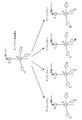
- FIG. 2 is a diagram illustrating a plurality of orientations of the NV center of the magnetic resonance member 1 in FIG. 1.
- FIG. 3 is a diagram illustrating the frequency characteristics of the fluorescence intensity of the NV center after Zeeman splitting corresponding to a plurality of orientations of the NV center.
- FIG. 4 is a perspective view illustrating an application direction of the magnetic field Bt to be measured in the first embodiment.
- FIG. 5 is a perspective view illustrating an application direction of the magnetic field Bt to be measured in the second embodiment.
- FIG. 6 is a perspective view illustrating an application direction of the magnetic field Bt to be measured in the third embodiment.
- FIG. 1 is a diagram showing a configuration of a magnetic field measuring device according to an embodiment of the present invention.
- the magnetic field measuring device shown in FIG. 1 includes a magnetic sensor unit 10, an arithmetic processing unit 11, and a high-frequency power supply 12.
- the magnetic sensor unit 10 detects the magnetic field Bt to be measured (for example, its strength) at a predetermined position (for example, on or above the surface of the object to be inspected).
- the magnetic field to be measured may be a DC magnetic field, an AC magnetic field having a single frequency, or an AC magnetic field having a plurality of frequency components and having a predetermined period.
- the magnetic sensor unit 10 includes a magnetic resonance member 1 and a high-frequency magnetic field generator 2. Further, if necessary, the magnetic sensor unit 10 includes a static magnetic field generating unit 3.
- the magnetic resonance member 1 has a diamond crystal containing a plurality of diamond nitrogen-vacancy centers (NV centers). That is, the magnetic resonance member 1 is an ensemble magnetic resonance member, and in this embodiment, it is used as an optical detection magnetic resonance member.
- the magnetic resonance member 1 is a diamond crystal plate and is fixed to the support member 1a.
- the high frequency magnetic field generator 2 applies a microwave described later to the magnetic resonance member 1.
- the high frequency power supply 12 generates the microwave current and conducts it to the high frequency magnetic field generator 2.
- the high-frequency magnetic field generator 2 is a kind of, for example, a coil, an LC resonance device, a slit antenna, a rod-shaped antenna, or a combination of a plurality of these devices.
- the static magnetic field generation unit 3 applies a static magnetic field (DC magnetic field) that Zeeman splits the energy level of the NV center in the magnetic resonance member 1.
- a static magnetic field DC magnetic field
- a permanent magnet, a coil (that is, an electromagnet), or the like is used as the static magnetic field generating unit 3.
- a DC power supply is provided, electrically connected to the coil, and a DC current is supplied to the coil, whereby a static magnetic field is generated.
- the NV center in the magnetic resonance member 1 has an energy level capable of Zeeman splitting, and has a plurality of directions (that is, the above-mentioned NV direction) in which the shift widths of the energy levels during Zeeman splitting are different from each other. obtain.
- the magnetic sensor unit 10 includes an irradiation device 4 and a light receiving device 5 as a detection device for detecting a physical event (here, fluorescence) corresponding to a magnetic field to be measured from the magnetic resonance member 1.
- the irradiation device 4 irradiates the magnetic resonance member 1 as the light detection magnetic resonance member with light (excitation light having a predetermined wavelength and measurement light having a predetermined wavelength).
- the light receiving device 5 detects the fluorescence emitted from the magnetic resonance member 1 when the measurement light is irradiated.
- this physical event is optically detected here, it may be a change in electrical characteristics (such as a change in the resistance value of the magnetic resonance member 1) or may be electrically detected.
- FIG. 2 is a diagram illustrating a plurality of orientations of the NV center of the magnetic resonance member 1 in FIG. 1.
- an NV center is formed by defects (pores) (V) and nitrogen (N) as impurities.
- defects pores
- N nitrogen
- the magnetic resonance member 1 includes a plurality of (one of two, three, or four) NV centers in the NV direction among the four NV directions, and is on a diamond crystal lattice. Based on the positional relationship between nitrogen and vacancies, each NV center has one of four NV directions and is sensitive to components parallel to the NV direction in the measured magnetic field Bt. Therefore, it reacts to the measured magnetic field Bt with an intensity corresponding to the angle formed by the NV direction and the measured magnetic field Bt.
- the plurality of NV centers in the magnetic resonance member 1 are arranged in the directions of a plurality of predetermined axes (hereinafter referred to as target axes) among the four axes indicating the four bonding directions of the carbon atoms in the diamond crystal. Includes the NV center.
- the magnetic resonance member 1 is arranged in a direction that maximizes the sensitivity of the measured magnetic field Bt by the NV centers arranged in the directions of the above-mentioned target axes with respect to the measured magnetic field Bt.
- FIG. 3 is a diagram illustrating the frequency characteristics of the fluorescence intensity after Zeeman splitting (characteristics of the fluorescence intensity with respect to the microwave frequency) of the NV center corresponding to a plurality of orientations of the NV center.
- a static magnetic field Bo is applied to the magnetic resonance member 1
- the sub-levels after Zeeman splitting in the four NV centers in the NV directions are different from each other, and as shown in FIG.
- different dip frequency pairs (fi +, fi ⁇ ) appear corresponding to each direction i.
- four dip frequency pairs (fi +, fi ⁇ ) appear individually corresponding to the above-mentioned four NV directions i.
- the above-mentioned microwave has a frequency component including a predetermined dip frequency (that is, a microwave frequency at which the fluorescence intensity drops in ODMR) corresponding to the above-mentioned target axis with respect to the measured magnetic field Bt.
- a predetermined dip frequency that is, a microwave frequency at which the fluorescence intensity drops in ODMR
- this predetermined dip frequency is after the Zeeman split as shown in FIG. 3, and the static magnetic field Bo is applied to the magnetic resonance member 1. If not, this predetermined dip frequency is in the non-Zeman split state.
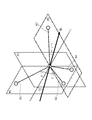
- FIG. 4 is a perspective view illustrating the application direction of the magnetic field Bt to be measured in the first embodiment.
- the above-mentioned target axis is set to two axes A1 and A2 among the above-mentioned four axes A1 to A4 in FIG. 4, and the angle of the measured magnetic field Bt with respect to one of the target axes A1 and A2 is set.
- the value of the variable that maximizes the sensitivity here, the sum of the components parallel to the two axes A1 and A2 in the measured magnetic field Bt sets the bond angle of the carbon atom in the diamond crystal to ⁇ (about 109 degrees). ), It becomes ((180- ⁇ ) / 2) degrees.
- the measured magnetic field Bt is a four-axis A1 to A4 indicating four bonding directions of carbon atoms in the diamond crystal in the magnetic resonance member 1.
- the magnetic resonance member 1 is arranged so that the direction of Bt is substantially parallel to the planes P1 and P3 and substantially perpendicular to the plane P2.
- the above-mentioned microwave has a frequency component including a predetermined dip frequency corresponding to the above-mentioned two axes A1 and A2.
- the magnitudes of the components in the target axes A1 and A2 directions in the measured magnetic field Bt are Bt ⁇ cos ((180- ⁇ ) / 2), respectively, and the components in the axes A3 and A4 directions.
- the size is 0. Therefore, the sensitivity of the magnetic resonance member 1 in the first embodiment is 2 ⁇ cos ((180- ⁇ ) / 2) times (that is, about 1.63 times) as compared with the reference sensitivity.
- the reference sensitivity is the sensitivity of the NV center in which the magnetic field Bt to be measured is applied to the magnetic resonance member 1 in parallel with only one axis of the diamond crystal, and the direction of the one axis is the NV direction. be.
- the arithmetic processing unit 11 includes, for example, a computer, executes a program on the computer, and operates as various processing units.
- the arithmetic processing unit 11 stores the detected optical or electrical signal data in a storage device (memory or the like) which is not shown, and controls and operates the measurement control unit 21 and the arithmetic unit 22. I do.
- the measurement control unit 21 controls the high frequency power supply 12 and specifies the detected value of the physical event (here, the intensity of fluorescence) detected by the above-mentioned detection device (here, the irradiation device 4 and the light receiving device 5).
- the measurement control unit 21 controls the high frequency power supply 12 and the irradiation device 4 according to a predetermined measurement sequence based on ODMR, and specifies the detected amount of fluorescence detected by the light receiving device 5.
- the irradiation device 4 is provided with a laser diode or the like as a light source
- the light receiving device 5 is provided with a photodiode or the like as a light receiving element
- the measurement control unit 21 is obtained by amplifying the output signal of the light receiving element or the like.
- the above-mentioned detection light amount is specified based on the output signal of the light receiving device 5.
- the calculation unit 22 calculates the measured magnetic field based on the detected value obtained by the measurement control unit 21 and stored in the storage device.
- the measurement control unit 21 controls the high frequency power supply 12 and the irradiation device 4 in a predetermined measurement sequence to specify the detection value of the above-mentioned physical event.
- the measurement sequence is set according to the frequency of the magnetic field to be measured and the like. For example, if the measured magnetic field is a DC magnetic field, a magnetic field that increases monotonically at a relatively low speed, or a magnetic field that monotonically decays at a relatively low speed, a Ramsey pulse sequence is applied to this measurement sequence, and the measured magnetic field is a magnetic field to be measured.
- a spin echo pulse sequence (such as a Hahn echo sequence) is applied to this measurement sequence.
- the measurement sequence is not limited to this.
- the measured magnetic field is a relatively low frequency AC magnetic field
- magnetic field measurements are performed multiple times in one cycle of the measured magnetic field in a Ramsey pulse sequence (that is, a DC magnetic field measurement sequence), and those magnetic fields are measured.
- the measured magnetic field intensity, waveform, etc. may be specified based on the measurement result.
- the magnetic sensor unit 10 is arranged so that the magnetic resonance member 1 is arranged as described above according to the direction of the magnetic field Bt to be measured.
- the measurement control unit 21 executes a predetermined measurement sequence, acquires the detection value (here, the fluorescence intensity) of the physical event of the magnetic resonance member 1 from the magnetic sensor unit 10, and the calculation unit 22 detects the detection value. Based on the value, specify the magnetic field (strength, etc.) at the measurement position. At that time, the intensity of the physical event (here, fluorescence) due to the plurality of target axes is synthesized, so that the detected value becomes large and the sensitivity becomes high.
- the detection value here, the fluorescence intensity
- the measurement control unit 21 conducts the microwave current including the frequency component of the dip frequency corresponding to the target axis to the high frequency magnetic field generator 2 by the high frequency power supply 12 at a predetermined timing. , The high frequency magnetic field generator 2 is made to apply such a microwave to the magnetic resonance member 1.
- the magnetic resonance member 1 has a diamond crystal containing a plurality of diamond nitrogen-vacancy centers
- the high frequency magnetic field generator 2 has a microwave on the magnetic resonance member 1.
- the above-mentioned plurality of diamond nitrogen-vacancy centers are diamond nitrogen-vacancy centers arranged in the directions of a plurality of predetermined target axes among the four axes indicating the four bonding directions of carbon atoms in the diamond crystal.
- the above-mentioned magnetic resonance member 1 substantially maximizes the sensitivity of the measured magnetic field Bt due to the diamond nitrogen-vacancy centers arranged in the directions of the above-mentioned plurality of predetermined target axes with respect to the measured magnetic field Bt. It is arranged in the direction of.
- the target axis is two of the four axes indicating the four bonding directions of the carbon atoms in the diamond crystal in the magnetic resonance member 1, and the magnetic resonance member 1 is the diamond.
- the bond angle of the carbon atom in the crystal is ⁇
- the magnetic field Bt to be measured forms approximately ((180- ⁇ ) / 2) degrees with respect to the two axes of the target axis, respectively, and the remaining of the four axes. They are arranged so as to form approximately 90 degrees with respect to each of the two axes.
- the measured magnetic field Bt is applied at an optimum angle with respect to the target axis (two axes in the first embodiment), so that the measured magnetic field Bt is detected with good sensitivity.
- FIG. 5 is a perspective view illustrating the application direction of the magnetic field Bt to be measured in the second embodiment.
- the above-mentioned target axis is the three axes A1, A2, A3 of the above-mentioned four axes A1 to A4, and the bond angle of the carbon atom in the diamond crystal is ⁇ (). Approximately 109 degrees), the measured magnetic field Bt with respect to the straight line L passing through the center between the two axes A1 and A2 of the four axes indicating the four bonding directions of the carbon atoms in the diamond crystal in the magnetic resonance member 1.
- ⁇ be the angle of, and if this ⁇ is a variable, the value of the variable that maximizes the sensitivity (here, the sum of the components parallel to the three axes A1 to A3 in the measured magnetic field Bt) is arctan (tan ( ⁇ ). It becomes / 2) / 3).
- the magnetic field Bt to be measured has (a) the same angle with respect to the above-mentioned two axes A1 and A2, and (b) the above-mentioned ⁇ is substantially arctan. It is arranged so as to be (tan ( ⁇ / 2) / 3).
- the direction of the magnetic field Bt to be measured is substantially parallel to the plane P2.
- the magnetic resonance member 1 is arranged so as to intersect the plane P1 at a substantially angle ⁇ .
- the above-mentioned microwave has a frequency component including a predetermined dip frequency corresponding to the above-mentioned three axes A1, A2, A3.
- the magnitudes of the components in the target axis A1 and A2 directions in the measured magnetic field Bt are Bt ⁇ cos ( ⁇ ) ⁇ cos ( ⁇ / 2), respectively, and the components in the target axis A3 direction.
- the reference sensitivity is the same as that described above.
- the target axes are set to three axes, and the measured magnetic field Bt is applied at an optimum angle to the target axes, so that the measured magnetic field Bt has good sensitivity. Is detected by.
- FIG. 6 is a perspective view illustrating an application direction of the magnetic field Bt to be measured in the third embodiment.
- the sensitivity (
- the value of the variable that maximizes the sum of the components parallel to the four axes A1 to A4 in the measured magnetic field Bt is (about 109 degrees) when the bond angle of the carbon atom in the diamond crystal is ⁇ (about 109 degrees). It becomes ⁇ / 2) degrees.
- the magnetic resonance member 1 has a magnetic field Bt to be measured with respect to four axes indicating four bonding directions of carbon atoms in the diamond crystal in the magnetic resonance member 1. , Are arranged so as to form approximately ( ⁇ / 2) degrees.
- the magnetic resonance member 1 is arranged so that the direction of Bt is substantially parallel to the planes P1 and P2 and substantially perpendicular to the plane P3.
- the magnitudes of the components of the measured magnetic field Bt in the directions of the axes A1, A2, A3, and A4 are Bt ⁇ cos ( ⁇ / 2), respectively. Therefore, the sensitivity of the magnetic resonance member 1 in the third embodiment is (4 ⁇ cos ( ⁇ / 2)) times (that is, about 2.32 times) as compared with the reference sensitivity.
- the reference sensitivity is the same as that described above.
- the target axes are set to four axes, and the measured magnetic field Bt is applied at an optimum angle to the target axes, so that the measured magnetic field Bt has good sensitivity. Is detected by.
- the present invention is applicable to, for example, a magnetic field measuring device and a magnetic field measuring method.
Landscapes
- Physics & Mathematics (AREA)
- General Physics & Mathematics (AREA)
- Condensed Matter Physics & Semiconductors (AREA)
- Health & Medical Sciences (AREA)
- Chemical & Material Sciences (AREA)
- Life Sciences & Earth Sciences (AREA)
- Analytical Chemistry (AREA)
- Biochemistry (AREA)
- General Health & Medical Sciences (AREA)
- Immunology (AREA)
- Pathology (AREA)
- Nuclear Medicine, Radiotherapy & Molecular Imaging (AREA)
- High Energy & Nuclear Physics (AREA)
- Measuring Magnetic Variables (AREA)
- Investigating, Analyzing Materials By Fluorescence Or Luminescence (AREA)
Abstract
磁気共鳴部材1は、複数のダイヤモンド窒素-空孔中心を含むダイヤモンド結晶を有し、高周波磁場発生器2は、磁気共鳴部材1にマイクロ波の磁場を印加する。上述の複数のダイヤモンド窒素-空孔中心は、ダイヤモンド結晶における炭素原子の4つの結合方向を示す4軸のうちの所定の複数の対象軸の方向にそれぞれ配列しているダイヤモンド窒素-空孔中心を含み、上述の磁気共鳴部材1は、被測定磁場Btに対して、上述の所定の複数の対象軸の方向にそれぞれ配列しているダイヤモンド窒素-空孔中心による被測定磁場Btの感度を略最大とする向きに配置されている。
Description
本発明は、磁場測定装置および磁場測定方法に関するものである。
ある磁気計測装置は、電子スピン共鳴を利用した光検出磁気共鳴(ODMR:Optically Detected Magnetic Resonance)で磁気計測を行っている(例えば特許文献1参照)。
ODMRでは、サブレベルの準位と光学遷移準位とをもつ磁気共鳴部材に高周波磁場(マイクロ波)と光をそれぞれサブレベル間の励起と光遷移間の励起のために照射することで、サブレベル間の磁気共鳴による占有数の変化などが光信号により高感度で検出される。通常、基底状態の電子が緑光で励起された後、基底状態に戻る際に赤光を発する。一方、例えば、ダイヤモンド構造中の窒素と格子欠陥(以下、ダイヤモンド窒素-空孔中心(NVセンタ:Nitrogen Vacancy Center)という)中の電子は、2.87GHz程度の高周波磁場の照射により、光励起により初期化された後では、基底状態中の3つのサブレベルの中で一番低いレベル(スピン磁気量子数ms=0)から、基底状態中のそれより高いエネルギー軌道のレベル(ms=±1)に遷移する。その状態の電子が緑光で励起されると、無輻射で基底状態中の3つのサブレベルの中で一番低いレベル(ms=0)に戻るため発光量が減少し、この光検出より、高周波磁場により磁気共鳴が起こったかどうかを知ることができる。ODMRでは、このような、NVセンタを有するダイヤモンドといった光検出磁気共鳴部材が使用される。
そして、NVセンタを使用した直流磁場の測定方法として、ラムゼイパルスシーケンス(Ramsey Pulse Sequence)を使用した測定方法がある。ラムゼイパルスシーケンスでは、(a)励起光をNVセンタに照射し、(b)マイクロ波の第1のπ/2パルスをNVセンタに印加し、(c)第1のπ/2パルスから所定の時間間隔ttでマイクロ波の第2のπ/2パルスをNVセンタに印加し、(d)測定光をNVセンタに照射してNVセンタの発光量を測定し、(e)測定した発光量に基づいて磁束密度を見積もれる。
また、NVセンタを使用した交流磁場の測定方法として、スピンエコーパルスシーケンス(Spin Echo Pulse Sequence)を使用した測定方法がある。スピンエコーパルスシーケンスでは、(a)励起光をNVセンタに照射し、(b)マイクロ波の第1のπ/2パルスを被測定磁場の位相0度でNVセンタに印加し、(c)マイクロ波のπパルスを被測定磁場の位相180度でNVセンタに印加し、(d)マイクロ波の第2のπ/2パルスを被測定磁場の位相360度でNVセンタに印加し、(e)測定光をNVセンタに照射してNVセンタの発光量を測定し、(f)測定した発光量に基づいて磁束密度を見積もれる。
ダイヤモンド窒素-空孔中心(NVセンタ)は、窒素と空孔との配列方向(以下、N-V方向ともいう)に対して平行な磁場成分に対して感度を有するため、N-V方向に対する被測定磁場Btの方向によっては、被測定磁場Btが良好な感度で検出されない可能性がある。
本発明は、上記の問題に鑑みてなされたものであり、被測定磁場Btを良好な感度で検出する磁場測定装置および磁場測定方法を得ることを目的とする。
本発明に係る磁場測定装置は、複数のダイヤモンド窒素-空孔中心を含むダイヤモンド結晶を有する磁気共鳴部材と、磁気共鳴部材にマイクロ波の磁場を印加する高周波磁場発生器と、高周波磁場発生器にマイクロ波の電流を導通させる高周波電源と、磁気共鳴部材から、被測定磁場に対応する物理的事象を検出する検出装置と、高周波電源を制御し、検出装置により検出された物理的事象の検出値を特定する測定制御部と、その検出値に基づいて被測定磁場を演算する演算部とを備える。そして、上述の複数のダイヤモンド窒素-空孔中心は、ダイヤモンド結晶における炭素原子の4つの結合方向を示す4軸のうちの所定の複数の軸の方向にそれぞれ配列しているダイヤモンド窒素-空孔中心を含み、上述の磁気共鳴部材は、被測定磁場に対して、上述の所定の複数の軸の方向にそれぞれ配列しているダイヤモンド窒素-空孔中心による被測定磁場の感度を略最大とする向きに配置されている。
本発明に係る磁場測定方法は、複数のダイヤモンド窒素-空孔中心を含むダイヤモンド結晶を有する磁気共鳴部材にマイクロ波の磁場を印加するステップと、磁気共鳴部材から被測定磁場に対応する物理的事象を検出し物理的事象の検出値を特定するステップと、検出値に基づいて被測定磁場を演算するステップとを備える。そして、上述の複数のダイヤモンド窒素-空孔中心は、ダイヤモンド結晶における炭素原子の4つの結合方向を示す4軸のうちの所定の複数の軸の方向にそれぞれ配列しているダイヤモンド窒素-空孔中心を含み、上述の磁気共鳴部材は、被測定磁場に対して、上述の所定の複数の軸の方向にそれぞれ配列しているダイヤモンド窒素-空孔中心による被測定磁場の感度を略最大とする向きに配置されている。
本発明によれば、被測定磁場Btを良好な感度で検出する磁場測定装置および磁場測定方法を得ることができる。
以下、図に基づいて本発明の実施の形態を説明する。
実施の形態1.
図1は、本発明の実施の形態に係る磁場測定装置の構成を示す図である。図1に示す磁場測定装置は、磁気センサ部10と、演算処理装置11と、高周波電源12とを備える。
磁気センサ部10は、所定の位置(例えば、検査対象物体の表面上または表面上方)において、被測定磁場Bt(例えばその強度など)を検出する。なお、被測定磁場は、直流磁場でもよいし、単一周波数の交流磁場でもよいし、複数の周波数成分を有する所定周期の交流磁場でもよい。
この実施の形態では、磁気センサ部10は、磁気共鳴部材1および高周波磁場発生器2を備える。また、必要に応じて、磁気センサ部10は、静磁場発生部3を備える。
磁気共鳴部材1は、複数のダイヤモンド窒素-空孔中心(NVセンタ)を含むダイヤモンド結晶を有する。つまり、磁気共鳴部材1は、アンサンブルな磁気共鳴部材であり、この実施の形態では、光検出磁気共鳴部材として使用される。ここでは、磁気共鳴部材1は、ダイヤモンド結晶の板材であって、支持部材1aに固定されている。
高周波磁場発生器2は、後述のマイクロ波を磁気共鳴部材1に印加する。ここでは、高周波電源12は、そのマイクロ波の電流を生成して高周波磁場発生器2に導通させる。高周波磁場発生器2は例えばコイルや、LC共振装置や、スリットアンテナや、棒状アンテナなどの一種であるか、それらの複数の装置を組み合わせたものである。
なお、静磁場発生部3は、磁気共鳴部材1内のNVセンタのエネルギー準位をゼーマン分裂させる静磁場(直流磁場)を印加する。静磁場発生部3としては、永久磁石、コイル(つまり、電磁石)などが使用される。静磁場発生部3としてはコイルが使用される場合、直流電源が設けられ、そのコイルに電気的に接続され、そのコイルに直流電流を供給し、これにより、静磁場が発生する。NVセンタでは、基底状態がms=0,+1,-1の三重項状態であり、ms=+1の準位およびms=-1の準位が上述の静磁場によってゼーマン分裂する。磁気共鳴部材1におけるNVセンタは、ゼーマン分裂可能なエネルギー準位を有し、また、ゼーマン分裂時のエネルギー準位のシフト幅が互いに異なる複数の向き(つまり、上述のN-V方向)を取り得る。
また、この実施の形態では、磁気センサ部10は、磁気共鳴部材1から、被測定磁場に対応する物理的事象(ここでは蛍光)を検出する検出装置として、照射装置4および受光装置5を備える。照射装置4は、光検出磁気共鳴部材としての磁気共鳴部材1に光(所定波長の励起光と所定波長の測定光)を照射する。受光装置5は、測定光の照射時において磁気共鳴部材1から発せられる蛍光を検出する。なお、この物理的事象は、ここでは光学的に検出されるが、電気特性の変化(磁気共鳴部材1の抵抗値の変化など)であってもよく、電気的に検出されてもよい。
図2は、図1における磁気共鳴部材1のNVセンタの複数の向きについて説明する図である。図2に示すように、ダイヤモンド結晶において、欠陥(空孔)(V)および不純物としての窒素(N)によってNVセンタが形成される。ダイヤモンド結晶内の欠陥(空孔,V)に対して、隣接する窒素(N)の取り得る位置(つまり、N-V方向)は4種類ある。
磁気共鳴部材1は、この4つのN-V方向のうちの複数(2つ、3つ、4つのうちのいずれか)のN-V方向のNVセンタを含んでおり、ダイヤモンド結晶格子上での窒素および空孔の位置関係に基づき、各NVセンタは、4つのN-V方向のいずれかを有し、被測定磁場Btにおける、N-V方向に対して平行な成分に対して感度を有するため、そのN-V方向と被測定磁場Btとのなす角度に応じた強度で、被測定磁場Btに反応する。
このように、磁気共鳴部材1内の複数のNVセンタは、ダイヤモンド結晶における炭素原子の4つの結合方向を示す4軸のうちの所定の複数の軸(以下、対象軸という)の方向にそれぞれ配列しているNVセンタを含む。そして、磁気共鳴部材1は、被測定磁場Btに対して、上述の対象軸の方向にそれぞれ配列しているNVセンタによる被測定磁場Btの感度を略最大とする向きに配置されている。
図3は、NVセンタの複数の向きに対応するNVセンタのゼーマン分裂後の蛍光強度の周波数特性(マイクロ波周波数に対する蛍光強度の特性)について説明する図である。なお、磁気共鳴部材1に静磁場Boが印加されている場合には、4つのN-V方向のNVセンタにおけるゼーマン分裂後のサブ準位が互いに異なり、図3に示すように、マイクロ波の周波数に対する蛍光強度の特性において、それぞれの向きiに対応して、互いに異なるディップ周波数対(fi+,fi-)が現れる。このように、上述の4つのN-V方向iに対応して、4つのディップ周波数対(fi+,fi-)がそれぞれ個別的に現れる。
また、上述のマイクロ波は、被測定磁場Btに対して上述の対象軸に対応する所定のディップ周波数(つまり、ODMRにおいて蛍光強度が落ち込むマイクロ波周波数)を含む周波数成分を有する。静磁場Boが磁気共鳴部材1に印加されている場合には、この所定のディップ周波数は、図3に示すようなゼーマン分裂後のものであり、静磁場Boが磁気共鳴部材1に印加されていない場合には、この所定のディップ周波数は、ゼーマン分裂していない状態のものである。
図4は、実施の形態1における被測定磁場Btの印加方向を説明する斜視図である。
実施の形態1では、上述の対象軸を図4における上述の4軸A1~A4のうちの2軸A1,A2とし、対象軸A1,A2のうちの一方の軸に対する被測定磁場Btの角度を変数とすると、感度(ここでは、被測定磁場Btにおける2軸A1,A2にそれぞれ平行な成分の和)を最大にする変数の値は、ダイヤモンド結晶における炭素原子の結合角をθ(約109度)としたとき、((180-θ)/2)度となる。
したがって、実施の形態1では、図4に示すように、磁気共鳴部材1は、被測定磁場Btが、磁気共鳴部材1内のダイヤモンド結晶における炭素原子の4つの結合方向を示す4軸A1~A4のうちの2軸A1,A2に対して、それぞれ略((180-θ)/2)度をなし、その4軸のうちの残りの2軸A3,A4に対して、それぞれ略90度をなすように配置されている。
つまり、図4に示すように、軸A1,A2の張る平面をP1とし、軸A3,A4の張る平面をP2とし、平面P1,P2の両方に垂直な平面をP3としたとき、被測定磁場Btの方向が平面P1,P3に対して略平行であり、かつ平面P2に対して略垂直となるように、磁気共鳴部材1は配置される。
したがって、実施の形態1では、上述のマイクロ波は、上述の2軸A1,A2に対応する所定のディップ周波数を含む周波数成分を有する。
実施の形態1では、被測定磁場Btのうちの対象軸A1,A2方向の成分の大きさは、それぞれ、Bt×cos((180-θ)/2)となり、軸A3,A4方向の成分の大きさは、0となる。したがって、実施の形態1での磁気共鳴部材1の感度は、基準感度に比べ、2×cos((180-θ)/2)倍(つまり、約1.63倍)となる。ここで、基準感度は、ダイヤモンド結晶の1軸のみに対して平行に被測定磁場Btを磁気共鳴部材1に印加し、その1軸の方向がN-V方向となっているNVセンタによる感度である。
図1に戻り、演算処理装置11は、例えばコンピュータを備え、プログラムをコンピュータで実行して、各種処理部として動作する。この実施の形態では、演算処理装置11は、検出された光学的あるいは電気的な信号データを図示せぬ記憶装置(メモリーなど)に保存し、測定制御部21および演算部22として制御および演算動作を行う。
測定制御部21は、高周波電源12を制御し、上述の検出装置(ここでは、照射装置4および受光装置5)により検出された物理的事象(ここでは蛍光の強度)の検出値を特定する。
この実施の形態では、測定制御部21は、ODMRに基づき、所定の測定シーケンスに従って高周波電源12および照射装置4を制御し、受光装置5により検出された蛍光の検出光量を特定する。例えば、照射装置4は、レーザーダイオードなどを光源として備え、受光装置5は、フォトダイオードなどを受光素子として備え、測定制御部21は、受光素子の出力信号に対して増幅などを行って得られる受光装置5の出力信号に基づいて、上述の検出光量を特定する。
演算部22は、測定制御部21によって得られ、記憶装置に保存されていた検出値に基づいて被測定磁場を演算する
例えば、測定制御部21は、所定測定シーケンスで高周波電源12および照射装置4を制御して、上述の物理的事象の検出値を特定する。この実施の形態では、この測定シーケンスは、被測定磁場の周波数などに従って設定される。例えば、被測定磁場が直流磁場、比較的低速で単調増加する磁場、または比較的低速で単調減衰する磁場である場合には、この測定シーケンスには、ラムゼイパルスシーケンスが適用され、被測定磁場が比較的高周波数の交流磁場である場合には、この測定シーケンスには、スピンエコーパルスシーケンス(ハーンエコーシーケンスなど)が適用される。ただし、測定シーケンスは、これに限定されるものではない。例えば、被測定磁場が比較的低周波数の交流磁場である場合、被測定磁場の1周期において、複数回、ラムゼイパルスシーケンス(つまり、直流磁場の測定シーケンス)で、磁場測定を行い、それらの磁場測定の結果に基づいて、被測定磁場(強度、波形など)を特定するようにしてもよい。
次に、実施の形態1に係る磁場測定装置の動作について説明する。
まず、磁気センサ部10が、被測定磁場Btの方向に応じて上述のように磁気共鳴部材1が配置されるように配置される。
次に、測定制御部21は、所定の測定シーケンスを実行し、磁気共鳴部材1の物理的事象の検出値(ここでは蛍光強度)を磁気センサ部10から取得し、演算部22は、その検出値に基づいて、測定位置の磁場(強度など)を特定する。その際、複数の対象軸による物理的事象(ここでは蛍光)の強度が合成されることで検出値が大きくなり、感度が高くなる。
その測定シーケンスにおいて、測定制御部21は、所定のタイミングで、高周波電源12で、上述のように対象軸に対応するディップ周波数の周波数成分を含むマイクロ波の電流を高周波磁場発生器2に導通させ、高周波磁場発生器2にそのようなマイクロ波を磁気共鳴部材1に印加させる。
以上のように、上記実施の形態1によれば、磁気共鳴部材1は、複数のダイヤモンド窒素-空孔中心を含むダイヤモンド結晶を有し、高周波磁場発生器2は、磁気共鳴部材1にマイクロ波の磁場を印加する。上述の複数のダイヤモンド窒素-空孔中心は、ダイヤモンド結晶における炭素原子の4つの結合方向を示す4軸のうちの所定の複数の対象軸の方向にそれぞれ配列しているダイヤモンド窒素-空孔中心を含み、上述の磁気共鳴部材1は、被測定磁場Btに対して、上述の所定の複数の対象軸の方向にそれぞれ配列しているダイヤモンド窒素-空孔中心による被測定磁場Btの感度を略最大とする向きに配置されている。
具体的には、実施の形態1では、対象軸は、磁気共鳴部材1内のダイヤモンド結晶における炭素原子の4つの結合方向を示す4軸のうちの2軸であり、磁気共鳴部材1は、ダイヤモンド結晶における炭素原子の結合角をθとしたときに、被測定磁場Btが対象軸の2軸に対してそれぞれ略((180-θ)/2)度をなし、その4軸のうちの残りの2軸に対して、それぞれ略90度をなすように配置されている。
これにより、対象軸(実施の形態1では2軸)に対して最適な角度で被測定磁場Btが印加されるため、被測定磁場Btが良好な感度で検出される。
実施の形態2.
図5は、実施の形態2における被測定磁場Btの印加方向を説明する斜視図である。
実施の形態2では、図5に示すように、上述の対象軸が、上述の4軸A1~A4のうちの3軸A1,A2,A3とされ、ダイヤモンド結晶における炭素原子の結合角をθ(約109度)としたときに、磁気共鳴部材1内のダイヤモンド結晶における炭素原子の4つの結合方向を示す4軸のうちの2軸A1,A2の間の中心を通る直線Lに対する被測定磁場Btの角度をαとし、このαを変数とすると、感度(ここでは、被測定磁場Btにおける3軸A1~A3にそれぞれ平行な成分の和)を最大にする変数の値は、arctan(tan(θ/2)/3)となる。
したがって、実施の形態2では、磁気共鳴部材1は、被測定磁場Btが、(a)上述の2軸A1,A2に対して同一の角度をなし、かつ、(b)上述のαが略arctan(tan(θ/2)/3)となるように配置されている。
つまり、図5に示すように、軸A1,A2の張る平面をP1とし、軸A3,A4の張る平面をP2としたとき、被測定磁場Btの方向が、平面P2に対して略平行であり、かつ、平面P1に対して略角度αで交差するように、磁気共鳴部材1は配置される。
したがって、実施の形態2では、上述のマイクロ波は、上述の3軸A1,A2,A3に対応する所定のディップ周波数を含む周波数成分を有する。
実施の形態2では、被測定磁場Btのうちの対象軸A1,A2方向の成分の大きさは、それぞれ、Bt×cos(α)×cos(θ/2)となり、対象軸A3方向の成分の大きさは、Bt×cos(θ/2-α)となる。したがって、実施の形態2での磁気共鳴部材1の感度は、基準感度に比べ、(2×cos(α)×cos(θ/2)+cos(θ-α))倍(つまり、上述の角度αが約25.0度(=arctan(0.467))であるので、約1.92倍)となる。ここで、基準感度は、上述したものと同様である。
なお、実施の形態2に係る磁場測定装置のその他の構成および動作については実施の形態1と同様であるので、その説明を省略する。
以上のように、上記実施の形態2によれば、対象軸が3軸とされ、その対象軸に対して最適な角度で被測定磁場Btが印加されるため、被測定磁場Btが良好な感度で検出される。
実施の形態3.
図6は、実施の形態3における被測定磁場Btの印加方向を説明する斜視図である。
実施の形態3では、上述の対象軸を図6における上述の4軸A1~A4のすべてとし、対象軸A1~A4のうちの1つの軸に対する被測定磁場Btの角度を変数とすると、感度(ここでは、被測定磁場Btにおける4軸A1~A4にそれぞれ平行な成分の和)を最大にする変数の値は、ダイヤモンド結晶における炭素原子の結合角をθ(約109度)としたとき、(θ/2)度となる。
したがって、実施の形態3では、図6に示すように、磁気共鳴部材1は、被測定磁場Btが、磁気共鳴部材1内のダイヤモンド結晶における炭素原子の4つの結合方向を示す4軸に対して、それぞれ略(θ/2)度をなすように配置されている。
つまり、図6に示すように、軸A1,A2の張る平面をP1とし、軸A3,A4の張る平面をP2とし、平面P1,P2の両方に垂直な平面をP3としたとき、被測定磁場Btの方向が、平面P1,P2に対して略平行であり、かつ、平面P3に対して略垂直となるように、磁気共鳴部材1は配置される。
したがって、実施の形態3では、上述のマイクロ波は、上述の4軸A1~A4に対応する所定のディップ周波数を含む周波数成分を有する。
実施の形態3では、被測定磁場Btのうちの軸A1,A2,A3,A4の方向の成分の大きさは、それぞれ、Bt×cos(θ/2)となる。したがって、実施の形態3での磁気共鳴部材1の感度は、基準感度に比べ、(4×cos(θ/2))倍(つまり、約2.32倍)となる。ここで、基準感度は、上述したものと同様である。
なお、実施の形態3に係る磁場測定装置のその他の構成および動作については実施の形態1と同様であるので、その説明を省略する。
以上のように、上記実施の形態3によれば、対象軸が4軸とされ、その対象軸に対して最適な角度で被測定磁場Btが印加されるため、被測定磁場Btが良好な感度で検出される。
なお、上述の実施の形態に対する様々な変更および修正については、当業者には明らかである。そのような変更および修正は、その主題の趣旨および範囲から離れることなく、かつ、意図された利点を弱めることなく行われてもよい。つまり、そのような変更および修正が請求の範囲に含まれることを意図している。
本発明は、例えば、磁場測定装置および磁場測定方法に適用可能である。
Claims (6)
- 複数のダイヤモンド窒素-空孔中心を含むダイヤモンド結晶を有する磁気共鳴部材と、
前記磁気共鳴部材にマイクロ波の磁場を印加する高周波磁場発生器と、
前記高周波磁場発生器に前記マイクロ波の電流を導通させる高周波電源と、
前記磁気共鳴部材から、被測定磁場に対応する物理的事象を検出する検出装置と、
前記高周波電源を制御し、前記検出装置により検出された前記物理的事象の検出値を特定する測定制御部と、
前記検出値に基づいて前記被測定磁場を演算する演算部とを備え、
前記複数のダイヤモンド窒素-空孔中心は、前記ダイヤモンド結晶における炭素原子の4つの結合方向を示す4軸のうちの所定の複数の軸の方向にそれぞれ配列しているダイヤモンド窒素-空孔中心を含み、
前記磁気共鳴部材は、前記被測定磁場に対して、前記所定の複数の軸の方向にそれぞれ配列しているダイヤモンド窒素-空孔中心による前記被測定磁場の感度を略最大とする向きに配置されていること、
を特徴とする磁場測定装置。 - 前記マイクロ波は、前記被測定磁場に対して前記所定の複数の軸に対応する所定のディップ周波数を含む周波数成分を有することを特徴とする請求項1記載の磁場測定装置。
- 前記磁気共鳴部材は、前記ダイヤモンド結晶における炭素原子の結合角をθとしたときに、前記被測定磁場が、前記ダイヤモンド結晶における炭素原子の4つの結合方向を示す4軸のうちの2軸に対して、それぞれ略((180-θ)/2)度をなすように配置されており、
前記所定の複数の軸は、前記被測定磁場に対して略((180-θ)/2)度をなす前記2軸であること、
を特徴とする請求項1または請求項2記載の磁場測定装置。 - 前記磁気共鳴部材は、前記ダイヤモンド結晶における炭素原子の結合角をθとし、前記ダイヤモンド結晶における炭素原子の4つの結合方向を示す4軸のうちの2軸の間の中心を通る直線に対する前記被測定磁場の角度をαとしたとき、前記被測定磁場が、(a)前記2軸に対して同一の角度をなし、かつ、(b)前記αが略arctan(tan(θ/2)/3)となるように配置されており、
前記所定の複数の軸は、前記4軸のうちの前記2軸を含む3軸であること、
を特徴とする請求項1または請求項2記載の磁場測定装置。 - 前記磁気共鳴部材は、前記ダイヤモンド結晶における炭素原子の結合角をθとしたときに、前記被測定磁場が、前記ダイヤモンド結晶における炭素原子の4つの結合方向を示す4軸に対して、それぞれ略(θ/2)度をなすように配置されており、
前記所定の複数の軸は、前記4軸であること、
を特徴とする請求項1または請求項2記載の磁場測定装置。 - 複数のダイヤモンド窒素-空孔中心を含むダイヤモンド結晶を有する磁気共鳴部材にマイクロ波の磁場を印加するステップと、
前記磁気共鳴部材から被測定磁場に対応する物理的事象を検出し前記物理的事象の検出値を特定するステップと、
前記検出値に基づいて前記被測定磁場を演算するステップとを備え、
前記複数のダイヤモンド窒素-空孔中心は、前記ダイヤモンド結晶における炭素原子の4つの結合方向を示す4軸のうちの所定の複数の軸の方向にそれぞれ配列しているダイヤモンド窒素-空孔中心を含み、
前記磁気共鳴部材は、前記被測定磁場に対して、前記所定の複数の軸の方向にそれぞれ配列しているダイヤモンド窒素-空孔中心による前記被測定磁場の感度を略最大とする向きに配置されていること、
を特徴とする磁場測定方法。
Priority Applications (1)
| Application Number | Priority Date | Filing Date | Title |
|---|---|---|---|
| US17/922,473 US12140648B2 (en) | 2020-05-12 | 2021-04-15 | Magnetic field measurement apparatus and magnetic field measurement method |
Applications Claiming Priority (2)
| Application Number | Priority Date | Filing Date | Title |
|---|---|---|---|
| JP2020-083739 | 2020-05-12 | ||
| JP2020083739A JP7465467B2 (ja) | 2020-05-12 | 2020-05-12 | 磁場測定装置および磁場測定方法 |
Publications (1)
| Publication Number | Publication Date |
|---|---|
| WO2021229993A1 true WO2021229993A1 (ja) | 2021-11-18 |
Family
ID=78511247
Family Applications (1)
| Application Number | Title | Priority Date | Filing Date |
|---|---|---|---|
| PCT/JP2021/015543 Ceased WO2021229993A1 (ja) | 2020-05-12 | 2021-04-15 | 磁場測定装置および磁場測定方法 |
Country Status (3)
| Country | Link |
|---|---|
| US (1) | US12140648B2 (ja) |
| JP (1) | JP7465467B2 (ja) |
| WO (1) | WO2021229993A1 (ja) |
Families Citing this family (5)
| Publication number | Priority date | Publication date | Assignee | Title |
|---|---|---|---|---|
| JP7194327B2 (ja) * | 2018-07-03 | 2022-12-22 | スミダコーポレーション株式会社 | 磁場測定装置および磁場測定方法 |
| JP7397429B2 (ja) * | 2020-06-04 | 2023-12-13 | スミダコーポレーション株式会社 | 励起光照射装置および励起光照射方法 |
| EP4435423A4 (en) * | 2021-11-19 | 2025-11-12 | Sumida Corp | NUCLEAR MAGNETIC RESONANCE DETECTION DEVICE AND NUCLEAR MAGNETIC RESONANCE DETECTION METHOD |
| JP7784299B2 (ja) * | 2021-12-28 | 2025-12-11 | 矢崎総業株式会社 | センサ |
| CN120752545A (zh) * | 2023-02-21 | 2025-10-03 | Lg电子株式会社 | 基于金刚石氮-空位传感器的磁传感装置 |
Citations (4)
| Publication number | Priority date | Publication date | Assignee | Title |
|---|---|---|---|---|
| US20180136291A1 (en) * | 2016-11-08 | 2018-05-17 | Linh M. Pham | Methods and apparatus for optically detecting magnetic resonance |
| US20190178959A1 (en) * | 2016-06-06 | 2019-06-13 | President And Fellows Of Harvard College | Simultaneous vector magnetometry with nitrogen vacancy centers in diamond or other solid-state spin sensors |
| US20200049776A1 (en) * | 2018-08-07 | 2020-02-13 | Alexander Wood | Quantum spin magnetometer |
| WO2021054141A1 (ja) * | 2019-09-17 | 2021-03-25 | 国立大学法人京都大学 | 測定装置および測定方法 |
Family Cites Families (3)
| Publication number | Priority date | Publication date | Assignee | Title |
|---|---|---|---|---|
| JP2012110489A (ja) | 2010-11-24 | 2012-06-14 | Sumitomo Electric Ind Ltd | 磁気計測装置、及び、磁気センサ素子の製造方法 |
| JP6278462B2 (ja) * | 2014-07-17 | 2018-02-14 | 日本電信電話株式会社 | 磁場検出方法 |
| CN108333207B (zh) * | 2018-03-19 | 2020-03-31 | 中国科学技术大学 | 一种零场顺磁共振的测量方法以及测量系统 |
-
2020
- 2020-05-12 JP JP2020083739A patent/JP7465467B2/ja active Active
-
2021
- 2021-04-15 US US17/922,473 patent/US12140648B2/en active Active
- 2021-04-15 WO PCT/JP2021/015543 patent/WO2021229993A1/ja not_active Ceased
Patent Citations (4)
| Publication number | Priority date | Publication date | Assignee | Title |
|---|---|---|---|---|
| US20190178959A1 (en) * | 2016-06-06 | 2019-06-13 | President And Fellows Of Harvard College | Simultaneous vector magnetometry with nitrogen vacancy centers in diamond or other solid-state spin sensors |
| US20180136291A1 (en) * | 2016-11-08 | 2018-05-17 | Linh M. Pham | Methods and apparatus for optically detecting magnetic resonance |
| US20200049776A1 (en) * | 2018-08-07 | 2020-02-13 | Alexander Wood | Quantum spin magnetometer |
| WO2021054141A1 (ja) * | 2019-09-17 | 2021-03-25 | 国立大学法人京都大学 | 測定装置および測定方法 |
Also Published As
| Publication number | Publication date |
|---|---|
| JP2021179327A (ja) | 2021-11-18 |
| US20230184853A1 (en) | 2023-06-15 |
| US12140648B2 (en) | 2024-11-12 |
| JP7465467B2 (ja) | 2024-04-11 |
Similar Documents
| Publication | Publication Date | Title |
|---|---|---|
| WO2021229993A1 (ja) | 磁場測定装置および磁場測定方法 | |
| JP5264242B2 (ja) | 原子磁力計及び磁力計測方法 | |
| JP7369344B2 (ja) | 磁場測定装置および磁場測定方法 | |
| JP6290488B2 (ja) | センサシステムにおける光ポンプビーム制御 | |
| JP7194327B2 (ja) | 磁場測定装置および磁場測定方法 | |
| JP6731458B2 (ja) | 磁力計システムの較正 | |
| JP2017026402A (ja) | 光ポンピング磁力計及び磁気センシング方法 | |
| US10816616B2 (en) | Phase shifted magnetometry adaptive cancellation | |
| US10036797B2 (en) | Electron spin resonance apparatus | |
| CN111819454B (zh) | 用于测量磁场方向的方法和设备 | |
| JP2015227871A (ja) | 原子センサシステム | |
| US9829545B2 (en) | Apparatus and method for hypersensitivity detection of magnetic field | |
| KR20140099201A (ko) | Mr 데이터를 획득하고 b1 자기장을 판정하는 방법 및 이에 대응하여 설계된 자기 공명 시스템 | |
| WO2020071383A1 (ja) | センサ素子、測定装置および測定方法 | |
| JP7675365B2 (ja) | 磁場測定装置および磁場測定方法 | |
| US20260092993A1 (en) | Magnetic field measurement apparatus and magnetic field measurement method | |
| JP2025149785A (ja) | 測定装置および測定方法 | |
| WO2025204000A1 (ja) | 測定装置および測定方法 | |
| JPH11271412A (ja) | 磁気検出方法及び装置 | |
| JP2024057947A (ja) | 磁場測定装置 | |
| WO2025040868A1 (en) | Magnetometer |
Legal Events
| Date | Code | Title | Description |
|---|---|---|---|
| 121 | Ep: the epo has been informed by wipo that ep was designated in this application |
Ref document number: 21804403 Country of ref document: EP Kind code of ref document: A1 |
|
| NENP | Non-entry into the national phase |
Ref country code: DE |
|
| 122 | Ep: pct application non-entry in european phase |
Ref document number: 21804403 Country of ref document: EP Kind code of ref document: A1 |