WO2021229945A1 - 同軸コネクタ - Google Patents
同軸コネクタ Download PDFInfo
- Publication number
- WO2021229945A1 WO2021229945A1 PCT/JP2021/013705 JP2021013705W WO2021229945A1 WO 2021229945 A1 WO2021229945 A1 WO 2021229945A1 JP 2021013705 W JP2021013705 W JP 2021013705W WO 2021229945 A1 WO2021229945 A1 WO 2021229945A1
- Authority
- WO
- WIPO (PCT)
- Prior art keywords
- leaf spring
- coaxial connector
- spring portion
- contact
- leg
- Prior art date
- Legal status (The legal status is an assumption and is not a legal conclusion. Google has not performed a legal analysis and makes no representation as to the accuracy of the status listed.)
- Ceased
Links
Images


Classifications
-
- H—ELECTRICITY
- H01—ELECTRIC ELEMENTS
- H01R—ELECTRICALLY-CONDUCTIVE CONNECTIONS; STRUCTURAL ASSOCIATIONS OF A PLURALITY OF MUTUALLY-INSULATED ELECTRICAL CONNECTING ELEMENTS; COUPLING DEVICES; CURRENT COLLECTORS
- H01R24/00—Two-part coupling devices, or either of their cooperating parts, characterised by their overall structure
- H01R24/38—Two-part coupling devices, or either of their cooperating parts, characterised by their overall structure having concentrically or coaxially arranged contacts
Definitions
- the present invention relates to a coaxial connector.
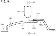
- FIG. 1A shows a vertical cross section of the movable terminal 120 and the fixed terminal 122.
- FIG. 1B shows a cross section at line IB-IB of FIG. 1A.
- the fixed terminal 122 includes a base portion 122a and a contact portion 122b.
- the base portion 122a is fixed to the main body of the coaxial connector (not shown).
- the contact portion 122b protrudes from the base portion 122a.
- the movable terminal 120 includes a base portion 120a, a leaf spring portion 120b, and a contact portion 120c.
- the base portion 120a is fixed to the main body of the coaxial connector.
- the leaf spring portion 120b protrudes from the base portion 120a and extends toward the fixed terminal 122.
- the contact portion 120c is connected to the tip of the leaf spring portion 120b and overlaps under the contact portion 122b of the fixed terminal 122.
- the contact portion 120c of the movable terminal 120 is in contact with the contact portion 122b of the fixed terminal 122 due to the upward elastic force of the leaf spring portion 120b.
- an antenna is connected to a fixed terminal 122 and a transmission / reception circuit is connected to a movable terminal 120.
- a transmission / reception circuit is connected to the antenna via the movable terminal 120 and the fixed terminal 122.
- the communication device is used in this state.
- the electrical characteristics of the transmitter / receiver circuit are inspected during manufacturing and maintenance of communication equipment.
- a dedicated measuring instrument is used for this inspection.
- the probe 130 of the mating coaxial connector connected to the measuring instrument is inserted into the coaxial connector from above the leaf spring portion 120b of the movable terminal 120 toward the leaf spring portion 120b. enter in.
- the probe 130 comes into contact with the leaf spring portion 120b and pushes down the leaf spring portion 120b as it is.
- the contact portion 120c of the movable terminal 120 is separated from the contact portion 122b of the fixed terminal 122, and the probe 130 is connected to the movable terminal 120.
- the measuring instrument is connected to the transmission / reception circuit via the probe 130 and the movable terminal 120. In this state, the electrical characteristics of the transmission / reception circuit are inspected.
- the probe 130 normally contacts the center of the leaf spring portion 120b of the movable terminal 120 in the width direction. However, as shown by the alternate long and short dash line in FIG. 1B, the probe 130 may come into contact with a position deviated from the center in the width direction of the leaf spring portion 120b. When the probe 130 comes into contact with a position largely deviated from the center of the leaf spring portion 120b in the width direction, the probe 130 is slippery further outward in the width direction of the leaf spring portion 120b from the position where the probe 130 first contacts. In this case, the contact state between the probe 130 and the leaf spring portion 120b is more likely to change than when the probe 130 comes into contact with the center of the leaf spring portion 120b in the width direction.
- the contact resistance between the probe 130 and the movable terminal 120 is likely to change. Therefore, when inspecting the electrical characteristics of the transmission / reception circuit, the measurement accuracy in a high frequency region such as a millimeter wave region may be impaired. For this reason, it is desired to be able to accurately measure the electrical characteristics of the circuit connected to the coaxial connector.
- an object of the present invention is to provide a coaxial connector capable of accurately measuring the electrical characteristics of a circuit connected to the coaxial connector.
- the coaxial connector according to the embodiment of the present invention includes a main body, a fixed terminal, and a movable terminal.
- the main body has an internal space. A hole communicating with the internal space is formed in the upper part of the main body.
- the fixed terminal is housed in the main body and includes a base portion and a contact portion.
- the base of the fixed terminal is fixed to the main body.
- the contact portion of the fixed terminal projects from the base of the fixed terminal into the internal space of the main body.
- the movable terminal is housed in the main body and includes a base portion, a leaf spring portion, a contact portion, and a leg portion. The base of the movable terminal is fixed to the main body.
- the leaf spring portion projects from the base of the movable terminal into the internal space of the main body and extends toward the contact portion of the fixed terminal.
- the leaf spring portion has an auxiliary contact area that intersects the central axis of the hole in the body.
- the contact portion of the movable terminal is connected to the tip of the leaf spring portion and is in contact with the contact portion of the fixed terminal from below.
- the legs are provided on both sides of the leaf spring portion. Each of the legs extends while bending so as to project in a direction different from the extending direction of the leaf spring portion, and is in contact with the bottom of the internal space of the main body.
- the coaxial connector according to the embodiment of the present invention includes a main body, a fixed terminal, and a movable terminal.
- the main body has an internal space. A hole communicating with the internal space is formed in the upper part of the main body.
- the fixed terminal is housed in the main body and includes a base portion and a contact portion.
- the base of the fixed terminal is fixed to the main body.
- the contact portion of the fixed terminal projects from the base of the fixed terminal into the internal space of the main body.
- the movable terminal is housed in the main body and includes a base portion, a leaf spring portion, a contact portion, and a leg portion. The base of the movable terminal is fixed to the main body.
- the leaf spring portion projects from the base of the movable terminal into the internal space of the main body and extends toward the contact portion of the fixed terminal.
- the leaf spring portion has an auxiliary contact area that intersects the central axis of the hole in the body.
- the contact portion of the movable terminal is connected to the tip of the leaf spring portion and is in contact with the contact portion of the fixed terminal from below.
- the legs project from both sides of the leaf spring portion and are in contact with the bottom of the internal space of the main body.
- the electrical characteristics of the circuit connected to the coaxial connector can be accurately measured.
- FIG. 1A is a vertical sectional view of a movable terminal and a fixed terminal in a conventional coaxial connector.
- FIG. 1B is a cross-sectional view (at the time of probe contact) in line IB-IB of FIG. 1A.
- FIG. 2A is a view of the coaxial connector according to the embodiment of the present invention when viewed from diagonally above.
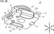
- FIG. 2B is a view of the coaxial connector according to the embodiment of the present invention when viewed from diagonally below.
- FIG. 3A is a view when the coaxial connector is disassembled and viewed from diagonally above.
- FIG. 3B is a view when the coaxial connector is disassembled and viewed from diagonally below.
- FIG. 4 is a vertical sectional view of the coaxial connector.
- FIG. 1A is a vertical sectional view of a movable terminal and a fixed terminal in a conventional coaxial connector.
- FIG. 1B is a cross-sectional view (at the time of probe contact
- FIG. 5A is a top view of the movable terminal.
- FIG. 5B is a rear view of the movable terminal.
- FIG. 6 is a vertical cross-sectional view of the coaxial connector showing a state when inspecting the electrical characteristics of the circuit connected to the coaxial connector.
- FIG. 7A is a cross-sectional view of the movable terminal showing the initial state in which the probe comes into contact with the movable terminal.
- FIG. 7B is a cross-sectional view of the movable terminal showing a state in which the probe is pushed further downward after coming into contact with the movable terminal.
- FIG. 8A is a perspective view of a movable terminal provided in the coaxial connector of the first modification.
- FIG. 8B is a top view of the movable terminal shown in FIG.
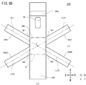
- FIG. 9A is a perspective view of a movable terminal provided in the coaxial connector of the second modification.
- 9B is a top view of the movable terminal shown in FIG. 9A.
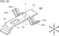
- FIG. 10 is a perspective view of a movable terminal provided in the coaxial connector of the third modification.
- FIG. 11 is a cross-sectional view of the movable terminal in another modified example.
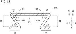
- FIG. 12 is a cross-sectional view of the movable terminal in still another modified example.
- FIG. 13 is a cross-sectional view of the movable terminal in still another modified example.
- FIG. 14 is a cross-sectional view of the movable terminal in still another modified example.
- FIG. 15 is a top view of the movable terminal in still another modified example.
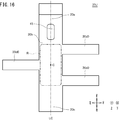
- FIG. 16 is a top view of the movable terminal in still another modified example.
- the coaxial connector of one embodiment includes a main body, a fixed terminal, and a movable terminal.
- the main body has an internal space. A hole communicating with the internal space is formed in the upper part of the main body.
- the fixed terminal is housed in the main body and includes a base portion and a contact portion. The base of the fixed terminal is fixed to the main body. The contact portion of the fixed terminal projects from the base of the fixed terminal into the internal space of the main body.
- the movable terminal is housed in the main body and includes a base portion, a leaf spring portion, a contact portion, and a leg portion. The base of the movable terminal is fixed to the main body.
- the leaf spring portion projects from the base of the movable terminal into the internal space of the main body and extends toward the contact portion of the fixed terminal.
- the leaf spring portion has an auxiliary contact area that intersects the central axis of the hole in the body.
- the contact portion of the movable terminal is connected to the tip of the leaf spring portion and is in contact with the contact portion of the fixed terminal from below.
- the legs are provided on both sides of the leaf spring portion. Each of the legs extends while bending so as to project in a direction different from the extending direction of the leaf spring portion, and is in contact with the bottom of the internal space of the main body (first configuration).
- the auxiliary set in an appropriate range of the leaf spring portion (for example, between the legs provided on both sides of the leaf spring portion when viewed along the vertical direction).
- the contact position of the probe moves to the center of the width of the leaf spring as the probe enters. Moving. This is related to the fact that at a position deviated from the center in the width direction of the leaf spring portion, the elastic force of the leg portion closer to that position among the legs provided on both sides of the leaf spring portion acts strongly. There is. Details will be described later.
- the contact state between the probe and the leaf spring part is stabilized. That is, the contact resistance between the probe and the movable terminal is stable. Therefore, the measurement accuracy is stable in the measurement in the high frequency region such as the millimeter wave region. Therefore, according to the coaxial connector of the first configuration, the electrical characteristics of the circuit (for example, the transmission / reception circuit) connected to the coaxial connector can be accurately measured.
- the circuit for example, the transmission / reception circuit
- the coaxial connector of one embodiment includes a main body, a fixed terminal, and a movable terminal.
- the main body has an internal space. A hole communicating with the internal space is formed in the upper part of the main body.
- the fixed terminal is housed in the main body and includes a base portion and a contact portion.
- the base of the fixed terminal is fixed to the main body.
- the contact portion of the fixed terminal projects from the base of the fixed terminal into the internal space of the main body.
- the movable terminal is housed in the main body and includes a base portion, a leaf spring portion, a contact portion, and a leg portion. The base of the movable terminal is fixed to the main body.
- the leaf spring portion projects from the base of the movable terminal into the internal space of the main body and extends toward the contact portion of the fixed terminal.
- the leaf spring portion has an auxiliary contact area that intersects the central axis of the hole in the body.
- the contact portion of the movable terminal is connected to the tip of the leaf spring portion and is in contact with the contact portion of the fixed terminal from below.
- the legs project from both sides of the leaf spring portion and are in contact with the bottom of the internal space of the main body.
- the portion of the upper surface of the leaf spring portion pressed by the probe is the portion where each leg protrudes. Below.
- the leaf spring portion is curved so as to be convex downward.
- the elastic force of the leg portion of the leg portion protruding from both side portions of the leaf spring portion acts strongly on the contact position of the probe.
- the contact position of the probe moves toward the center of the leaf spring portion in the width direction. Therefore, according to the coaxial connector of the second configuration, the same effect as that of the coaxial connector of the first configuration can be obtained.
- the auxiliary contact region is located between the portions where the legs protrude in the leaf spring portion (third configuration). In this configuration, it is easy to obtain the effect of moving the probe in contact with the position deviated from the center of the leaf spring portion in the width direction in the auxiliary contact region to the center of the leaf spring portion in the width direction.
- a plurality of the legs may be provided on both sides of the leaf spring portion.
- the leg portion can include the first leg portion and the second leg portion.
- the first leg portion and the second leg portion project from both side portions of the leaf spring portion and come into contact with the bottom of the internal space.
- the second leg portion is provided so as to be adjacent to the first leg portion in the extending direction of the leaf spring portion.
- the auxiliary contact region is located in a range including a region between the portions where the first leg portion protrudes and a region between the portions where the second leg portion protrudes.
- Fourth configuration In the case of this configuration, it is easy to obtain the effect of moving the probe in contact with the position deviated from the center in the width direction of the leaf spring portion to the center in the width direction of the leaf spring portion in the auxiliary contact region.
- the extending direction of each leg portion is perpendicular to the extending direction of the leaf spring portion. It may be directional (fifth configuration).
- the extending direction of each of the first leg portions and the extending direction of each of the second leg portions are the leaf spring portions. It may be tilted from the extending direction (sixth configuration). Due to the structure of the coaxial connector, the fifth configuration or the sixth configuration can be appropriately adopted in consideration of the space in which the legs can be arranged.
- the first leg portion passes through the auxiliary contact region and is the third with respect to the line perpendicular to the extending direction of the leaf spring portion. It is preferable that the two legs are arranged symmetrically (seventh configuration). In the case of this configuration, in the vertical cross section of the leaf spring portion, the portion near the contact position of the probe in the auxiliary contact region can be prevented from being extremely inclined. As a result, the contact state between the probe and the leaf spring portion becomes more stable.
- the intersection of the center lines of the first leg is the center line of the second leg. It may coincide with the intersection (eighth configuration). In this case, the region on which the elastic force of the first leg and the elastic force of the second leg act can be concentrated around the intersection. Therefore, the contact state between the probe and the leaf spring portion is further stabilized.
- the shapes of the legs protruding from both side portions of the leaf spring portion are, for example, as follows.
- the legs are bent inward with each other (9th configuration).
- the legs are each bent downward and then bent outward from each other (tenth configuration).
- the legs are bent downward at an acute angle, and further bent outward at an acute angle (11th configuration).
- Each leg is bent downward at an obtuse angle and then upward at an obtuse angle (12th configuration). Due to the structure of the coaxial connector, any one of the ninth configuration to the twelfth configuration is appropriately adopted in consideration of the space in which the leg can be arranged and the elastic force of the leg to be applied to the leaf spring portion. Can be adopted.
- each leg may be connected to the side edge of the leaf spring (13th configuration).
- each of the legs may be connected to the upper surface of the leaf spring portion (14th configuration).
- Each of the legs can also be connected to the lower surface of the leaf spring portion (15th configuration).
- the leaf spring portion may be arranged at a corresponding position in the extending direction (16th configuration). Further, in any of the coaxial connectors having the first configuration to the fifteenth configuration, the portion where the leg portion protrudes on one side portion of the leaf spring portion and the leg portion protrudes on the other side portion of the leaf spring portion. The portion may be displaced from the position in the extending direction of the leaf spring portion (17th configuration).
- the vertical cross section means a cross section along the longitudinal direction of the movable terminal.
- the longitudinal direction of the movable terminal means the direction in which the movable terminal extends.
- the cross section means a cross section perpendicular to the longitudinal direction of the movable terminal.
- FIG. 4 is a vertical sectional view of the coaxial connector 10.
- the coaxial connector 10 includes a main body 12, a movable terminal 20, and a fixed terminal 22.
- the main body 12 includes a lower case 18, an upper case 16, and an external terminal 14.
- the external terminal 14, the movable terminal 20, and the fixed terminal 22 are all made of metal and have conductivity.
- the external terminal 14, the movable terminal 20, and the fixed terminal 22 are made of, for example, SUS301 (JIS standard) stainless steel.
- the lower case 18 and the upper case 16 are made of, for example, resin and have electrical insulating properties.
- the upper case 16 and the external terminal 14 are stacked in this order on the lower case 18.
- the direction in which the external terminal 14, the upper case 16, and the lower case 18 are overlapped is the vertical direction.
- the side where the external terminal 14 is arranged is the upper side with respect to the lower case 18, and the side where the lower case 18 is arranged is the lower side with respect to the external terminal 14.
- the movable terminal 20 and the fixed terminal 22 are arranged along a predetermined direction.
- the arrangement direction of the movable terminal 20 and the fixed terminal 22 is the front-back direction.
- the side where the movable terminal 20 is arranged with respect to the fixed terminal 22 is the front, and the side where the fixed terminal 22 is arranged with respect to the movable terminal 20 is the rear.
- the direction orthogonal to the vertical direction and the front-back direction is defined as the left-right direction.
- the direction rotated 90 ° clockwise from the front is defined as the right
- the direction rotated 90 ° counterclockwise from the front is defined as left.
- top, bottom, front, back, right, and left, as well as the up-down, front-back, and left-right directions defined above are used only for convenience of explanation and are the actual coaxial connectors of the present invention. It has nothing to do with the orientation.
- the length of the coaxial connector 10 in the vertical direction is, for example, 0.9 mm.
- the length of the coaxial connector 10 in the front-rear direction and the length in the left-right direction are, for example, 2 mm.
- the lower case 18 is a plate-shaped member having a substantially rectangular shape in a plan view.
- the lower case 18 includes, for example, a pair of sides along the front-rear direction and a pair of sides along the left-right direction.
- ridges 52a and 52b for positioning with the upper case 16 are provided on the upper surface of the lower case 18.
- the ridges 52a and 52b extend in the front-rear direction, and are provided at the right end and the left end of the upper surface of the lower case 18, respectively.
- a notch 54 is formed at the front end of the lower case 18 and at the central portion in the left-right direction. Through this notch 54, the front end portion 20F of the movable terminal 20 is exposed to the outside of the main body 12.
- a notch 55 is formed at the rear end of the lower case 18 at the central portion in the left-right direction. Through this notch 55, the rear end portion 22B of the fixed terminal 22 is exposed to the outside of the main body 12.
- a protrusion 56 is provided in the vicinity of the notch 54.
- the protrusion 56 plays a role of positioning the movable terminal 20.
- holes 53a and 53b that penetrate the lower case 18 in the thickness direction (vertical direction) are formed on the right side and the left side of the protrusion 56, respectively.
- the upper surface of the lower case 18 has a fixing surface 57 for fixing the movable terminal 20.
- the fixed surface 57 is located between the notch 54 on the front side and the protrusion 56 in the front-rear direction.
- the upper surface of the lower case 18 has a fixing surface 58 for fixing the fixing terminal 22.
- the fixed surface 58 is an upper surface of a trapezoidal portion protruding from the bottom B (see FIG. 4) of the internal space S described later. This trapezoidal portion is located in the vicinity of the notch 55 on the rear side and on the front side of the notch 55.
- the upper case 16 includes a cylindrical portion 34 and a cover portion 35.
- the cover portion 35 is a plate-shaped member. Seen along the vertical direction, the right end of the cover 35 has a shape complementary to the left end of the ridge 52a of the lower case 18. Similarly, the left end of the cover 35 has a shape complementary to the right end of the ridge 52b of the lower case 18.
- the cover portion 35 is fitted into the lower case 18 and covers the portion between the ridges 52a and the ridges 52b in the lower case 18.
- an internal space S is formed between the lower case 18 and the upper case 16.
- the cylindrical portion 34 of the upper case 16 projects upward from the center of the upper surface of the cover portion 35.
- the upper case 16 is formed with a hole 34a that penetrates the upper case 16 in the vertical direction.
- the hole 34a includes a space inside the cylindrical portion 34.
- the central axis C of the hole 34a is along the vertical direction.
- the hole 34a is circular in a cross section perpendicular to the vertical direction of the upper case 16.
- the central axis C passes through the center of the circle.
- the hole 34a may be rectangular in a cross section perpendicular to the vertical direction of the upper case 16.
- the central axis C passes through the intersection of the two diagonal lines of the rectangle.
- the cylindrical portion 34 has a pot-shaped shape in which the opening cross-sectional area increases toward the upper side.
- two cylindrical protrusions 36a and 36b protruding downward are provided on the lower surface of the upper case 16 (cover portion 35).
- the protrusions 36a and 36b are provided at positions corresponding to the holes 53a and 53b of the lower case 18, respectively.
- the protrusions 36a and 36b are inserted into the holes 53a and 53b of the lower case 18, respectively.
- the upper case 16 and the lower case 18 are positioned with each other.
- the lower surface of the upper case 16 (cover portion 35) has a fixed surface 37. Seen along the vertical direction, the fixed surface 37 is arranged at a position overlapping the fixed surface 57 (see FIG. 3A) of the lower case 18.
- the movable terminal 20 is fixed by sandwiching a portion near the front end portion 20F (base portion 20a described later) between the fixing surface 37 of the upper case 16 and the fixing surface 57 of the lower case 18.
- the lower surface of the upper case 16 (cover portion 35) has a fixed surface 39. Seen along the vertical direction, the fixed surface 39 is arranged at a position overlapping with the fixed surface 58 (see FIG. 3A) of the lower case 18.
- the fixing terminal 22 is fixed by sandwiching a portion near the rear end portion 22B (base portion 22a described later) between the fixing surface 39 of the upper case 16 and the fixing surface 58 of the lower case 18.
- the external terminal 14 comes into contact with the outer conductor of the other party coaxial connector for inspection, and normally functions as a ground terminal. As shown in FIGS. 2A and 2B, the external terminal 14 includes a flat portion 31, a cylindrical portion 32, and protruding portions 33a and 33b.
- the external terminal 14 is made of, for example, a stainless steel (for example, SUS301) plate.
- the external terminal 14 can be formed, for example, by subjecting a plate to various processes such as punching, bending, and drawing.
- the outer surface of the external terminal 14 is plated, if necessary.
- the flat portion 31 has a plate shape and covers the cover portion 35 of the upper case 16 from above. When viewed along the vertical direction, the flat portion 31 is substantially rectangular.
- the flat portion 31 includes, for example, a pair of sides along the front-rear direction and a pair of sides along the left-right direction.
- Protruding portions 33a and 33b are provided on the right and left sides of the flat portion 31, respectively.
- the protruding portions 33a and 33b are formed by bending a part of a plate-shaped body extending in the left-right direction from the flat portion 31. Specifically, as shown in FIG. 2B, the projecting portions 33a and 33b are bent so as to wrap around the lower surface of the lower case 18. As a result, the external terminal 14, the upper case 16, and the lower case 18 are fixed to each other.
- a cylindrical portion 32 protruding upward is provided in the central portion of the flat portion 31.
- the outer conductor (not shown) of the mating coaxial connector for inspection is fitted around the cylindrical portion 32.
- the cylindrical portion 32 is fitted around the cylindrical portion 34 so as to be coaxial with the cylindrical portion 34 of the upper case 16.
- a hole 34a is formed in the upper part of the main body 12. The hole 34a communicates with the internal space S (see FIG. 4).
- FIG. 5A is a top view of the movable terminal 20.
- FIG. 5B is a rear view of the movable terminal 20.
- the movable terminal 20 and the fixed terminal 22 are plate-shaped members made of metal, respectively.
- the movable terminal 20 and the fixed terminal 22 can be formed, for example, by punching and bending a flat metal plate.
- the movable terminal 20 and the fixed terminal 22 are housed in the main body 12.
- the fixed terminal 22 includes a base portion 22a and a contact portion 22b.
- the base portion 22a is a portion connected to the rear side of the contact portion 22b and is substantially in the same plane as the contact portion 22b.
- the base portion 22a is sandwiched between the fixed surface 58 of the lower case 18 and the fixed surface 39 of the upper case 16.
- the fixed terminal 22 is fixed to the main body 12.
- the portion rearward from the base portion 22a (rear end portion 22B) is exposed to the outside of the main body 12 via the notch 55.
- the contact portion 22b is a portion near the front end of the fixed terminal 22.
- the contact portion 22b projects from the base portion 22a into the internal space S of the main body 12. Since the fixed surface 58 is the upper surface of the trapezoidal portion protruding from the bottom B of the internal space S, the contact portion 22b is separated from the bottom B (upper surface of the lower case 18) of the internal space S.
- the movable terminal 20 is a plate-shaped member having springiness (elasticity).
- the movable terminal 20 includes a base portion 20a, a leaf spring portion 20b, a contact portion 20c, and leg portions 20d1, 20d1.
- the base portion 20a is a portion in the vicinity of the front end portion 20F of the movable terminal 20.
- the base 20a is sandwiched between the fixed surface 57 of the lower case 18 and the fixed surface 37 of the upper case 16. As a result, the movable terminal 20 is fixed to the main body 12.
- the portion on the front end side (front end portion 20F) of the base portion 20a is exposed to the outside of the main body 12 via the notch 54.
- the leaf spring portion 20b protrudes from the base portion 20a into the internal space S of the main body 12 and extends toward the contact portion 22b of the fixed terminal 22.
- the leaf spring portion 20b has an auxiliary contact region R.
- the auxiliary contact area R intersects the central axis C of the hole 34a of the main body 12.
- the contact portion 20c is a portion near the rear end of the movable terminal 20 and is connected to the tip of the leaf spring portion 20b.
- the contact portion 20c overlaps under the contact portion 22b of the fixed terminal 22.
- the movable terminal 20 is bent so that the leaf spring portion 20b and the contact portion 20c are separated from the bottom B (upper surface of the lower case 18) of the internal space S.
- the leaf spring portion 20b and the contact portion 20c are substantially parallel to the upper surface of the lower case 18.
- the contact portion 20c is in contact with the lower surface of the contact portion 22b of the fixed terminal 22 by the upward elastic force of the leaf spring portion 20b. From another viewpoint, the contact portion 20c is in contact with the contact portion 22b of the fixed terminal 22 from below.
- a hole 45 is formed in the leaf spring portion 20b in the vicinity of the base portion 20a.
- the protrusion 56 of the lower case 18 is inserted into the hole 45.
- the movable terminal 20 is positioned with respect to the lower case 18 in the front-rear direction and the left-right direction.
- the leaf spring portion 20b is provided with a pair of leg portions 20d1, 20d1.
- the pair of leg portions 20d1 and 20d1 project from both side portions of the leaf spring portion 20b and are in contact with the bottom B (upper surface of the lower case 18) of the internal space S. More specifically, the legs 20d1 and 20d1 are provided on both sides of the leaf spring portion 20b.
- Each of the legs 20d1 and 20d1 is connected to, for example, the side edge of the leaf spring portion 20b. That is, of the two legs 20d1 and 20d1, one leg 20d1 is connected to one side edge of the leaf spring portion 20b, and the other leg portion 20d1 is connected to the other side edge of the leaf spring portion 20b. ..
- the leg portions 20d1 and 20d1 may be integrally formed with the leaf spring portion 20b, or may be manufactured separately from the leaf spring portion 20b and then joined to the leaf spring portion 20b.
- Each of the leg portions 20d1 and 20d1 extends while bending so as to project in a direction different from the extending direction (front-back direction) of the leaf spring portion 20b.
- the direction along which the portions of the legs 20d1 and 20d1 having a curvature are along is different from the extending direction of the leaf spring portion 20b.
- each of the legs 20d1 and 20d1 is in contact with the bottom B of the internal space S of the main body 12. From another viewpoint, each of the leg portions 20d1 and 20d1 bends toward the bottom B of the internal space S while extending in a direction different from the direction in which the leaf spring portion 20b extends (front-rear direction).
- the legs 20d1 and 20d1 are arranged on the same straight line extending in the left-right direction when viewed along the vertical direction.
- the portions of the leaf spring portion 20b where the legs 20d1 and 20d1 protrude are positioned symmetrically with respect to the center line LC in the width direction of the leaf spring portion 20b. Have been placed.
- the portion where one leg portion 20d1 protrudes from one side portion of the leaf spring portion 20b is the portion where the other leg portion 20d1 protrudes from the other side portion of the leaf spring portion 20b, and the leaf spring portion. It is arranged at the corresponding position in the extending direction of 20b.
- the auxiliary contact region R is a region where the probe of the mating coaxial connector can come into contact.
- first boundary portions B1 where the leg portions 20d1 and 20d1 project respectively are shown by a two-dot chain line.
- the first boundary portion B1 is a boundary portion (connection portion) between the leaf spring portion 20b and each of the leg portions 20d1 and 20d1.
- the two first boundary portions B1 face each other in the width direction (left-right direction) of the leaf spring portion 20b.
- the auxiliary contact region R is located between the first boundary portions B1.
- each of the legs 20d1 and 20d1 are bent inward from each other. More specifically, each of the legs 20d1 and 20d1 extends outward in the left-right direction from the side portion of the leaf spring portion 20b, and further, at the portion on the tip end side (the end portion opposite to the leaf spring portion 20b). It is curved in a semi-circular shape in the plane along the vertical direction. The portions of the legs 20d1 and 20d1 including the tip approach each other as they approach the tip.
- the coaxial connector 10 is assembled, for example, as follows.
- the fixed terminal 22 is aligned and attached to the upper case 16, and then the movable terminal 20 is aligned and attached to the upper case 16.
- the upper surface of the contact portion 20c of the movable terminal 20 and the lower surface of the contact portion 22b of the fixed terminal 22 come into contact with each other.
- the protruding portions 33a and 33b of the external terminal 14 are not bent and extend in the same plane as the flat portion 31.
- the coaxial connector 10 is mounted on a communication device such as a mobile phone.
- the antenna of the communication device is connected to the externally exposed portion (rear end portion 22B) of the main body 12 at the fixed terminal 22.
- the transmission / reception circuit of the communication device is connected to a portion (front end portion 20F) exposed to the outside of the main body 12 in the movable terminal 20.
- the contact portion 20c of the movable terminal 20 is in contact with the contact portion 22b of the fixed terminal 22, the transmission / reception circuit is connected to the antenna via the movable terminal 20 and the fixed terminal 22. ing.
- the communication device is used in this state.
- FIG. 6 is a vertical cross-sectional view of the coaxial connector 10 showing a state when inspecting the electrical characteristics of the circuit connected to the coaxial connector 10.
- the probe 130 of the other coaxial connector connected to the measuring instrument is inserted into the hole 34a of the coaxial connector 10 from above.
- the outer conductor of the mating coaxial connector is not shown.
- the probe 130 of the other coaxial connector enters the coaxial connector 10 from above the leaf spring portion 20b of the movable terminal 20 toward the leaf spring portion 20b. Then, the probe 130 comes into contact with the leaf spring portion 20b and pushes down the leaf spring portion 20b as it is. As a result, the contact portion 20c of the movable terminal 20 is separated from the contact portion 22b of the fixed terminal 22. As a result, the electrical connection between the movable terminal 20 and the fixed terminal 22 is cut off, while the probe 130 is electrically connected to the movable terminal 20. Further, the outer conductor of the other coaxial connector is fitted to the outer terminal 14, and the outer conductor is electrically connected to the outer terminal 14. As a result, the measuring instrument is connected to the transmission / reception circuit via the probe 130 and the movable terminal 20. In this state, the electrical characteristics of the transmission / reception circuit are inspected.
- the vertical position of the contact portion 20c returns to the upper side due to the upward elastic force of the leaf spring portion 20b (see FIG. 4).
- the contact portion 20c of the movable terminal 20 comes into contact with the contact portion 22b of the fixed terminal 22.
- the movable terminal 20 is electrically connected to the fixed terminal 22 again, while the electrical connection between the probe 130 and the movable terminal 20 is cut off.
- the transmission / reception circuit is connected to the antenna via the movable terminal 20 and the fixed terminal 22. That is, the communication device is ready for use.
- 7A and 7B are cross-sectional views of the movable terminal 20 showing a state at the time of inspection.
- 7A and 7B show a leaf spring portion 20b including an auxiliary contact region R and leg portions 20d1, 20d1.
- FIG. 7A shows a state at the beginning when the probe 130 comes into contact with the movable terminal 20, that is, at the moment when the lowered probe 130 comes into contact with the movable terminal 20.
- FIG. 7B shows a state in which the probe 130 is pushed further downward after coming into contact with the auxiliary contact region R of the movable terminal 20.
- the probe 130 may come into contact with a position significantly deviated from the center in the width direction (left-right direction) of the leaf spring portion 20b.
- both side portions of the leaf spring portion 20b in the width direction are elastically supported by the leg portions 20d1 and 20d1, and the leaf spring portion 20b itself is supported. It can be elastically deformed. Therefore, as shown in FIG. 7B, when the probe 130 comes into contact with the auxiliary contact region R of the leaf spring portion 20b and then is pushed further downward, both the leaf spring portion 20b and the leg portions 20d1 and 20d1 are deformed.
- the legs 20d1 and 20d1 are deformed so as to be compressed in the vertical direction.
- the leaf spring portion 20b is curved so that the contact CP with the probe 130 and the portion in the vicinity thereof protrude downward. That is, in the cross section of the leaf spring portion 20b, the leaf spring portion 20b is curved so as to be convex downward.
- the elastic force of the right leg portion 20d1 close to the contact CP acts stronger than the elastic force of the left leg portion 20d1 on the initial contact CP with the probe 130 and its vicinity in the leaf spring portion 20b. ..
- the leaf spring portion 20b is curved so as to be convex downward, but the portion on the left side is lowered downward as compared with the portion on the right side of the contact CP.
- the contact CP and its vicinity are inclined downward to the left. Therefore, the probe 130 slides on the leaf spring portion 20b along the inclination of the leaf spring portion 20b. When the probe 130 is pushed further downward, the contact CP moves to the left side, that is, toward the center of the leaf spring portion 20b in the width direction (left-right direction).
- the contact CP When the contact CP reaches the center in the width direction of the leaf spring portion 20b, the elastic force acting from the left leg portion 20d1 and the elastic force acting from the right leg portion 20d1 become the same with respect to the contact CP. Therefore, in the cross section of the leaf spring portion 20b, the inclination of the contact CP and its vicinity is substantially eliminated. As a result, the contact CP does not move further in the left-right direction. That is, when the probe 130 is sufficiently pushed downward, the position of the contact CP is finally maintained at the center of the leaf spring portion 20b in the width direction.
- the moving direction of the probe 130 with the movement of the contact CP is indicated by an arrow.
- the contact CP is on the lower side (forward in the insertion direction of the probe 130) than the first boundary portion B1 on the upper surface of the leaf spring portion 20b. This state is obtained by supporting both ends of the auxiliary contact region R with respect to the width direction of the leaf spring portion 20b by the leg portions 20d1 and 20d1.
- both sides of the movable terminal 120 are not supported at least around the portion where the probe 130 contacts (see FIGS. 1A and 1B). Therefore, when the probe 130 comes into contact with a position largely deviated from the center of the leaf spring portion 120b in the width direction, the probe 130 is more slippery to the outside of the leaf spring portion 120b in the width direction from the position where the probe 130 first comes into contact. This is because the leaf spring portion 120b is twisted around the axis in the longitudinal direction of the leaf spring portion 120b, and the leaf spring portion 120b is tilted so as to be lowered in the width direction in the cross section of the leaf spring portion 120b.
- the above The mechanism works practically.
- the contact state between the probe 130 and the leaf spring portion 20b is stable. That is, the contact resistance between the probe 130 and the movable terminal 20 is stable.
- the measurement accuracy is stable in the measurement in the high frequency region such as the millimeter wave region. Therefore, the electrical characteristics of the circuit (transmission / reception circuit) connected to the coaxial connector 10 can be accurately measured.
- the leaf spring portion 20b When the leaf spring portion 20b is pressed by the probe 130, the leaf spring portion 20b has a contact point CP with the probe 130 and a portion in the vicinity thereof not only in the width direction (horizontal direction) but also in the longitudinal direction (front-back direction). May be deformed so as to protrude downward.
- FIG. 8A is a perspective view of the movable terminal 20A provided in the coaxial connector of the first modification.
- FIG. 8B is a top view of the movable terminal 20A.
- the movable terminal 20A can be used in place of the above-mentioned movable terminal 20 in the coaxial connector 10 according to the above embodiment.
- the movable terminal 20A of the first modification is different from the movable terminal 20 of the above embodiment in that a plurality of legs are provided on both sides of the leaf spring portion 20b.
- the plurality of legs provided on the leaf spring portion 20b include the first leg portions 20d1, 20d1 and the second leg portions 20d2, 20d2. That is, the movable terminal 20A includes a pair of first leg portions 20d1, 20d1 and a pair of second leg portions 20d2, 20d2. Similar to the legs 20d1, 20d1 described in the above embodiment, the first leg portions 20d1, 20d1 project from both side portions of the leaf spring portions 20b, respectively, and the bottom B of the internal space S of the main body 12 of the coaxial connector (FIG.
- the second leg portions 20d2 and 20d2 also protrude from both sides of the leaf spring portion 20b and come into contact with the bottom B (see FIG. 4) of the internal space S of the main body 12 of the coaxial connector. do.
- the second leg portions 20d2 and 20d2 are provided so as to be adjacent to the first leg portions 20d1 and 20d1 in the direction in which the leaf spring portion 20b extends (front-rear direction). That is, on each side of the leaf spring portion 20b, the first leg portion 20d1 and the second leg portion 20d2 are arranged in the front-rear direction.
- the second leg portions 20d2 and 20d2 are provided on the rear side of the first leg portions 20d1 and 20d1.
- Each of the leg portions 20d1, 20d1, 20d2, 20d2 is connected to the side edge of the leaf spring portion 20b, similarly to the leg portions 20d1, 20d1 of the above embodiment.
- the auxiliary contact region R is located in a range including a region between the first boundary portions B1 and a region between the second boundary portions B2.
- the first boundary portion B1 is a boundary portion (connection portion) between the leaf spring portion 20b and each of the first leg portions 20d1 and 20d1.
- the first boundary portion B1 means a portion of the side portions of the leaf spring portion 20b where the first leg portions 20d1 and 20d1 project respectively.
- the portions of the leaf spring portions 20b where the first leg portions 20d1 and 20d1 project that is, the first boundary portions B1 are formed on the leaf spring portions 20b.
- the portion where one first leg portion 20d1 protrudes from one side portion of the leaf spring portion 20b is the portion where the other first leg portion 20d1 protrudes from the other side portion of the leaf spring portion 20b, and the leaf spring. It is arranged at a corresponding position in the extending direction of the portion 20b.
- the second boundary portion B2 is a boundary portion (connection portion) between the leaf spring portion 20b and each of the second leg portions 20d2 and 20d2.
- the second boundary portion B2 means a portion of the side portion of the leaf spring portion 20b where the second leg portions 20d2 and 20d2 project respectively.
- the portions of the leaf spring portion 20b where the second leg portions 20d2 and 20d2 project, that is, the second boundary portions B2 are located on the leaf spring portion 20b. It is arranged at a position symmetrical with respect to the center line LC in the width direction.
- the portion where one second leg portion 20d2 protrudes from one side of the leaf spring portion 20b is the portion where the other second leg portion 20d2 protrudes from the other side portion of the leaf spring portion 20b, and the leaf spring. It is arranged at a corresponding position in the extending direction of the portion 20b.
- the auxiliary contact region R is located behind the front end of the first boundary portion B1 and before the rear end of the second boundary portion B2 in the front-rear direction.
- the extending directions of the first leg portions 20d1 and 20d1 are plates. It is tilted from the extending direction (front-back direction) of the spring portion 20b.
- the extending direction of each of the second leg portions 20d2 and 20d2 is inclined from the extending direction (front-back direction) of the leaf spring portion 20b. That is, when viewed along the vertical direction, the extending direction of each leg portion 20d1, 20d1, 20d2, 20d2 is the direction orthogonal to the extending direction of the leaf spring portion 20b and the extending direction of the leaf spring portion 20b (left-right direction).
- the two first leg portions 20d1 and 20d1 are the two first leg portions 20d1 and 20d1 with respect to the line LS perpendicular to the direction (front-back direction) in which the leaf spring portion 20b passes through the auxiliary contact region R and extends.
- the two legs are arranged substantially symmetrically with the two legs 20d2 and 20d2.
- the first leg portions 20d1, 20d1 are positioned symmetrically with respect to the second leg portions 20d2, 20d2 and the line LS.
- each leg portion 20d1, 20d1, 20d2, 20d2 extends radially around one point in the auxiliary contact region R.
- the region on which the elastic force of the first leg portions 20d1, 20d1 and the elastic force of the second leg portions 20d2, 20d2 act can be concentrated around the above intersection.
- the intersection of the center lines LC1 of the first leg portions 20d1 and 20d1 and the intersection of the center lines LC2 of the second leg portions 20d2 and 20d2 are holes in the main body 12. It is arranged on the central axis C of 34a (see FIG. 4).
- first leg portions 20d1, 20d1 and the second leg portions 20d2, 20d2 are bent inward from each other, similar to the leg portions 20d1, 20d1 of the movable terminal 20 shown in FIG. 5B.
- the coaxial connector provided with the movable terminal 20A can exert the same effect as the effect of the coaxial connector 10 described above.
- the movable terminal 20A includes the first leg portions 20d1, 20d1 and the second leg portions 20d2, 20d2, so that the auxiliary contact region is compared with the movable terminal 20 (see FIGS. 5A and 5B). R can be widened.
- the movable terminal 20A includes the first leg portion 20d1, 20d1 and the second leg portion 20d2, 20d2, the elastic force of each leg portion 20d1, 20d1, 20d2, 20d2 is increased, and the probe is used as the leaf spring portion 20b. It is possible to easily obtain the above-mentioned effect of moving to the central portion in the width direction of.
- the first leg portions 20d1, 20d1 and the second leg portions 20d2, 20d2 are arranged substantially symmetrically with respect to the line LS. There is.
- the portion near the contact position of the probe in the auxiliary contact region R can be prevented from being extremely inclined.
- the contact state between the probe and the leaf spring portion 20b becomes more stable.
- FIG. 9A is a perspective view of the movable terminal 20B provided in the coaxial connector of the second modification.
- FIG. 9B is a top view of the movable terminal 20B.
- the movable terminal 20B can be used in place of the above-mentioned movable terminal 20 in the coaxial connector 10 according to the above embodiment.
- the movable terminal 20B of the second modification includes the first leg portion 20d1, 20d1 and the second leg portion 20d2, 20d2, similarly to the movable terminal 20A of the first modification (see FIGS. 8A and 8B).
- the coaxial connector is viewed along the central axis C of the hole 34a (see FIG. 4) of the main body 12, that is, when viewed along the vertical direction, the extending directions of the first leg portions 20d1 and 20d1 are plates. This is a direction substantially perpendicular to the direction in which the spring portion 20b extends (front-back direction) (left-right direction).
- each of the second leg portions 20d2 and 20d2 is also a direction substantially perpendicular to the extending direction (front-back direction) of the leaf spring portion 20b (horizontal direction).
- the movable terminal 20B of the second modification is different from the movable terminal 20A of the first modification (see FIGS. 8A and 8B).
- the tip of each leg portion 20d1, 20d1, 20d2, 20d2 is located at the bottom B of the internal space S of the main body 12 as compared with the movable terminal 20A of the first modification. It can be arranged in a narrow area on (see FIG. 4).
- FIG. 10 is a perspective view of the movable terminal 20C provided in the coaxial connector of the third modification.
- the movable terminal 20C can be used in place of the above-mentioned movable terminal 20 in the coaxial connector 10 according to the above embodiment.
- the movable terminal 20C of the third modification includes the legs 20d3, 20d3, 20d4, and 20d4.
- the legs 20d3 and 20d3 are the first legs
- the legs 20d4 and 20d4 are the second legs.
- the extending direction of each of the first leg portions 20d3 and 20d3 and the extending direction of each of the second leg portions 20d4 and 20d4. Is a direction substantially perpendicular to the left-right direction, that is, the direction in which the leaf spring portion 20b extends (front-back direction).
- the first leg portions 20d3, 20d3 and the second leg portions 20d4, 20d4 have different shapes from the leg portions 20d1, 20d1, 20d2, 20d2 described in the above-described embodiment and each modification.
- Each of the first leg portions 20d3 and 20d3 extends outward in the left-right direction from the leaf spring portion 20b. More specifically, each of the first leg portions 20d3 and 20d3 is bent downward from the leaf spring portion 20b at an obtuse angle and further bent upward at an obtuse angle. In other words, each of the first leg portions 20d3 and 20d3 extends laterally and downwardly in the left-right direction and then extends outwardly and upwardly in the left-right direction from the leaf spring portion 20b. Therefore, each of the first leg portions 20d3 and 20d3 has a downwardly convex portion. At the bottom of this portion, each of the first leg portions 20d3 and 20d3 is in contact with the bottom B (see FIG. 4) of the internal space S of the main body 12.
- each of the second leg portions 20d4 and 20d4 extends outward in the left-right direction from the leaf spring portion 20b. More specifically, each of the second leg portions 20d4 and 20d4 is bent downward at an obtuse angle from the leaf spring portion 20b, and is further bent upward at an obtuse angle. In other words, each of the second leg portions 20d4 and 20d4 extends outwardly and downwardly in the left-right direction and then extends outwardly and upwardly in the left-right direction from the leaf spring portion 20b. Therefore, each of the second leg portions 20d4 and 20d4 has a downwardly convex portion. At the bottom of this portion, each of the second leg portions 20d4 and 20d4 is in contact with the bottom B (see FIG. 4) of the internal space S of the main body 12.
- each leg portion 20d3, 20d3, 20d4, 20d4 the portion on the tip end side from the lowermost portion can be used, for example, for fixing to the bottom B of the internal space S with resin.
- FIG. 11 is a cross-sectional view of the movable terminal 20D, which is a cross-sectional view of a portion including the leaf spring portion 20b and the leg portions 20d5 and 20d5.
- the leg portions 20d5 and 20d5 protruding from both side portions of the leaf spring portion 20b may be bent downward from the leaf spring portion 20b and further bent outward from each other. That is, each of the leg portions 20d5 and 20d5 may extend downward from the side portion of the leaf spring portion 20b, then curve outward in the left-right direction, and extend upward.
- FIG. 11 is a cross-sectional view of the movable terminal 20D, which is a cross-sectional view of a portion including the leaf spring portion 20b and the leg portions 20d5 and 20d5.
- the leg portions 20d5 and 20d5 protruding from both side portions of the leaf spring portion 20b may be bent downward from the leaf spring portion 20b and further bent outward from each other. That is, each of the leg portions 20d5
- the legs 20d5 and 20d5 each have a substantially J-shape. More specifically, in the cross section of the movable terminal 20D shown in FIG. 11, the upper half of each of the legs 20d5 and 20d5 extends in the vertical direction, and the lower half of each of the legs 20d5 and 20d5 is a semicircle opened upward. Have. At the bottom of this semi-circular portion, each of the legs 20d5 and 20d5 is in contact with the bottom B (see FIG. 4) of the interior space S.
- FIG. 12 is a cross-sectional view of the movable terminal 20E, which is a cross-sectional view of a portion including the leaf spring portion 20b and the leg portions 20d6 and 20d6.
- FIG. 12 shows a cross section of the leaf spring portion 20b and the leg portions 20d6 and 20d6 parallel to each other in the thickness direction.
- the legs 20d6 and 20d6 may extend outward from the leaf spring portion 20b in the left-right direction, then bend downward at an acute angle, and further bend outward at an acute angle. That is, each of the leg portions 20d6 and 20d6 may project from the side portion of the leaf spring portion 20b, extend inward and downward in the left-right direction, and then extend outward in the left-right direction.
- the legs 20d6 and 20d6 each have a substantially Z-shape in a cross section including the entire legs 20d6 and 20d6.
- each of the legs 20d6 and 20d6 has a first portion 61, a second portion 62, and a third portion 63.
- the first portion 61 extends outward in the left-right direction from the leaf spring portion 20b in the same plane as the leaf spring portion 20b.
- the second portion 62 extends downward and inward in the left-right direction from the tip end portion (the end portion on the side opposite to the leaf spring portion 20b) of the first portion 61.
- the angle ⁇ 1 formed by the first portion 61 and the second portion 62 is an acute angle (0 ° ⁇ 1 ⁇ 90 °).
- the third portion 63 extends outward in the left-right direction from the tip end portion of the second portion 62 (the end portion opposite to the first portion).
- the angle ⁇ 2 formed by the second portion 62 and the third portion 63 is an acute angle (0 ° ⁇ 2 ⁇ 90 °).
- the first portion 61 and the third portion 63 are substantially parallel to each other.
- the shape of the leg can be appropriately adopted in consideration of the space where the leg can be placed and the elastic force of the leg to be given to the leaf spring.
- each leg is connected to the side edge of the leaf spring in the movable terminal.
- each leg may be provided on the movable terminal so as to project from the side portion of the leaf spring portion, that is, the side edge of the leaf spring portion or its vicinity, and is necessarily connected to the side edge of the leaf spring portion.
- the legs 20d7 and 20d7 may be connected to the upper surface of the leaf spring portion 20b in the vicinity of both side edges of the leaf spring portion 20b.
- the legs 20d7 and 20d7 are bent inward from each other. That is, the portions of the legs 20d7 and 20d7 including the tip approach each other as they approach the tip, similar to the legs described in the above embodiment and the first and second modifications.
- the legs 20d8 and 20d8 may be connected to the lower surface of the leaf spring portion 20b in the vicinity of both side edges of the leaf spring portion 20b.
- the legs 20d8 and 20d8 are bent inward from each other. That is, the portions of the legs 20d8 and 20d8 including the tip approach each other as they approach the tip, similar to the legs described in the above embodiment and the first and second modifications.
- the portions of the leaf spring portion where the legs protrude are positioned symmetrically with respect to the center line in the width direction of the leaf spring portion.
- the portions of the leaf spring portion on which the legs protrude may be arranged at positions asymmetric with respect to the center line in the width direction of the leaf spring portion when viewed along the vertical direction.
- the portion where the leg portion 20d9 protrudes from one side of the leaf spring portion 20b is the portion where the leg portion 20d9 protrudes from the other side portion of the leaf spring portion 20b.
- the leaf spring portion 20b may be arranged so as to be displaced in the extending direction (front-back direction).
- the leg portion 20d9 protruding from the right side portion of the leaf spring portion 20b is arranged behind the leg portion 20d9 protruding from the left side portion of the leaf spring portion 20b.
- the number of legs provided on one side of the leaf spring portion of the movable terminal is equal to the number of legs provided on the other side.
- the number of legs 20d0 provided on one side of the leaf spring portion 20b and the number of legs 20d0, 20d0 provided on the other side are different. It may be different.
- two leg portions 20d0 and 20d0 protrude from the right side portion of the leaf spring portion 20b, and one leg portion 20d0 protrudes from the left side portion of the leaf spring portion 20b.
- the respective positions of the leg portions 20d0 and 20d0 provided on the right side portion of the leaf spring portion 20b and the leg portions provided on the left side portion of the leaf spring portion 20b It is out of alignment with the 20d0 position. More specifically, in the front-rear direction, the left leg portion 20d0 is arranged in the middle of the right leg portions 20d0 and 20d0.
- the present invention is useful for coaxial connectors, and in particular, it is possible to accurately measure the electrical characteristics of a circuit connected to a coaxial connector.
- Coaxial connector 12 Main body 14: External terminal 16: Upper case 18: Lower case 20, 20A, 20B, 20C, 20D, 20E, 20G, 20H, 20I, 20J: Movable terminal 20a: Base 20b: Leaf spring part 20c : Contact part 20d1, 20d2, 20d3, 20d4, 20d5, 20d6, 20d7, 20d8, 20d9, 20d0: Leg part 22: Fixed terminal 22a: Base part 22b: Contact part 34a: Hole 130: Probe B: Bottom B1: First boundary Part B2: Second boundary part C: Central axis R: Auxiliary contact area S: Internal space
Landscapes
- Coupling Device And Connection With Printed Circuit (AREA)
Priority Applications (1)
| Application Number | Priority Date | Filing Date | Title |
|---|---|---|---|
| JP2022522554A JP7364063B2 (ja) | 2020-05-14 | 2021-03-30 | 同軸コネクタ |
Applications Claiming Priority (2)
| Application Number | Priority Date | Filing Date | Title |
|---|---|---|---|
| JP2020-085325 | 2020-05-14 | ||
| JP2020085325 | 2020-05-14 |
Publications (1)
| Publication Number | Publication Date |
|---|---|
| WO2021229945A1 true WO2021229945A1 (ja) | 2021-11-18 |
Family
ID=78525639
Family Applications (1)
| Application Number | Title | Priority Date | Filing Date |
|---|---|---|---|
| PCT/JP2021/013705 Ceased WO2021229945A1 (ja) | 2020-05-14 | 2021-03-30 | 同軸コネクタ |
Country Status (3)
| Country | Link |
|---|---|
| JP (1) | JP7364063B2 (https=) |
| CN (1) | CN215896766U (https=) |
| WO (1) | WO2021229945A1 (https=) |
Citations (6)
| Publication number | Priority date | Publication date | Assignee | Title |
|---|---|---|---|---|
| JP3096377U (ja) * | 2003-03-11 | 2003-09-12 | インサート エンタープライズ カンパニ リミテッド | 超小型マイクロスイッチコネクタ |
| JP2005158359A (ja) * | 2003-11-21 | 2005-06-16 | Matsushita Electric Works Ltd | 接点部材およびそれを備えて成る同軸コネクタ |
| JP3142192U (ja) * | 2008-02-14 | 2008-06-05 | 詮欣股▲分▼有限公司 | 同軸コネクタ |
| JP3177068U (ja) * | 2012-05-07 | 2012-07-19 | 隆志工業股▲ふん▼有限公司 | 小型同軸コネクター |
| WO2016133348A1 (ko) * | 2015-02-16 | 2016-08-25 | 몰렉스 엘엘씨 | 동축 커넥터 및 그 조립방법 |
| CN210489870U (zh) * | 2019-01-15 | 2020-05-08 | 电连技术股份有限公司 | 一种微型射频开关 |
-
2021
- 2021-03-30 JP JP2022522554A patent/JP7364063B2/ja active Active
- 2021-03-30 WO PCT/JP2021/013705 patent/WO2021229945A1/ja not_active Ceased
- 2021-05-07 CN CN202120964212.7U patent/CN215896766U/zh active Active
Patent Citations (6)
| Publication number | Priority date | Publication date | Assignee | Title |
|---|---|---|---|---|
| JP3096377U (ja) * | 2003-03-11 | 2003-09-12 | インサート エンタープライズ カンパニ リミテッド | 超小型マイクロスイッチコネクタ |
| JP2005158359A (ja) * | 2003-11-21 | 2005-06-16 | Matsushita Electric Works Ltd | 接点部材およびそれを備えて成る同軸コネクタ |
| JP3142192U (ja) * | 2008-02-14 | 2008-06-05 | 詮欣股▲分▼有限公司 | 同軸コネクタ |
| JP3177068U (ja) * | 2012-05-07 | 2012-07-19 | 隆志工業股▲ふん▼有限公司 | 小型同軸コネクター |
| WO2016133348A1 (ko) * | 2015-02-16 | 2016-08-25 | 몰렉스 엘엘씨 | 동축 커넥터 및 그 조립방법 |
| CN210489870U (zh) * | 2019-01-15 | 2020-05-08 | 电连技术股份有限公司 | 一种微型射频开关 |
Also Published As
| Publication number | Publication date |
|---|---|
| CN215896766U (zh) | 2022-02-22 |
| JP7364063B2 (ja) | 2023-10-18 |
| JPWO2021229945A1 (https=) | 2021-11-18 |
Similar Documents
| Publication | Publication Date | Title |
|---|---|---|
| US8066516B2 (en) | Coaxial connector | |
| JP3473531B2 (ja) | 同軸コネクタ及び通信機装置 | |
| JP6593471B2 (ja) | 基板接続用電気コネクタ装置 | |
| KR101802731B1 (ko) | 스위치 부착 동축 커넥터 | |
| KR100432429B1 (ko) | 가동 단자 | |
| JP6256426B2 (ja) | 基板接続用電気コネクタ | |
| JP6179564B2 (ja) | 基板接続用電気コネクタ | |
| US10424860B2 (en) | Electrical connector and test method for electrical connector | |
| JP3473560B2 (ja) | 同軸コネクタ及びこの同軸コネクタを備えた通信機装置 | |
| WO2014013834A1 (ja) | 同軸コネクタ | |
| US20210344146A1 (en) | Electrical connector including a movable terminal having a substantially vertical securing portion with a pair of side arms insert-molded with an insulative base | |
| JPWO2014013833A1 (ja) | 同軸コネクタ | |
| CN111129849A (zh) | 电连接器 | |
| WO2021229945A1 (ja) | 同軸コネクタ | |
| CN108565552B (zh) | 天线装置、连接结构及终端设备 | |
| KR20130126501A (ko) | 스위치 부착 동축 커넥터 | |
| WO2022130704A1 (ja) | 同軸コネクタ | |
| US20220131305A1 (en) | Electrical connector including a movable terminal having first and second beams | |
| CN219677724U (zh) | 带有开关的同轴连接器 | |
| KR102902064B1 (ko) | 프로브 핀 | |
| JPH09147997A (ja) | 可動接触片の固定構造 | |
| JPH09223550A (ja) | 電気回路の高周波特性測定用のコネクタ | |
| JP2003059597A (ja) | 同軸コネクタ及び通信装置 |
Legal Events
| Date | Code | Title | Description |
|---|---|---|---|
| 121 | Ep: the epo has been informed by wipo that ep was designated in this application |
Ref document number: 21804401 Country of ref document: EP Kind code of ref document: A1 |
|
| ENP | Entry into the national phase |
Ref document number: 2022522554 Country of ref document: JP Kind code of ref document: A |
|
| NENP | Non-entry into the national phase |
Ref country code: DE |
|
| 122 | Ep: pct application non-entry in european phase |
Ref document number: 21804401 Country of ref document: EP Kind code of ref document: A1 |